nasa system safety handbook
TRANSCRIPT

NASA/SP-2010-580
Version 1.0
November 2011
NASA System Safety Handbook
Volume 1, System Safety Framework and Concepts for Implementation


i
NASA/SP-2010-580
Version 1.0
NASA System Safety Handbook
Volume 1, System Safety Framework and Concepts for Implementation
National Aeronautics and Space Administration
NASA Headquarters
Washington, D.C. 20546
November 2011

ii

iii
NASA STI Program … in Profile
Since its founding, NASA has been dedicated
to the advancement of aeronautics and space
science. The NASA scientific and technical
information (STI) program plays a key part in
helping NASA maintain this important role.
The NASA STI program operates under the
auspices of the Agency Chief Information
Officer. It collects, organizes, provides for
archiving, and disseminates NASA’s STI.
The NASA STI program provides access to
the NASA Aeronautics and Space Database
and its public interface, the NASA Technical
Report Server, thus providing one of the
largest collections of aeronautical and space
science STI in the world. Results are
published in both non-NASA channels and by
NASA in the NASA STI Report Series,
which includes the following report types:
TECHNICAL PUBLICATION. Reports of
completed research or a major significant
phase of research that present the results of
NASA Programs and include extensive data
or theoretical analysis. Includes compilations
of significant scientific and technical data and
information deemed to be of continuing
reference value. NASA counterpart of peer-
reviewed formal professional papers but has
less stringent limitations on manuscript length
and extent of graphic presentations.
TECHNICAL MEMORANDUM. Scientific
and technical findings that are preliminary or
of specialized interest, e.g., quick release
reports, working papers, and bibliographies
that contain minimal annotation. Does not
contain extensive analysis.
CONTRACTOR REPORT. Scientific and
technical findings by NASA-sponsored
contractors and grantees.
CONFERENCE PUBLICATION. Collected
papers from scientific and technical
conferences, symposia, seminars, or other
meetings sponsored or co-sponsored
by NASA.
SPECIAL PUBLICATION. Scientific,
technical, or historical information from
NASA programs, projects, and missions,
often concerned with subjects having
substantial public interest.
TECHNICAL TRANSLATION. English-
language translations of foreign scientific
and technical material pertinent to
NASA’s mission.
Specialized services also include creating
custom thesauri, building customized
databases, and organizing and publishing
research results.
For more information about the NASA STI
program, see the following:
Access the NASA STI program home page
at http://www.sti.nasa.gov
E-mail your question via the Internet to
Fax your question to the NASA STI Help
Desk at 443-757-5803
Phone the NASA STI Help Desk at
443-757-5802
Write to:
NASA STI Help Desk
NASA Center for Aerospace Information
7115 Standard Drive
Hanover, MD 21076-1320

iv
v
ACKNOWLEDGMENTS The project manager and the authors express their gratitude to NASA Office of Safety and Mission Assurance (OSMA) management (Mr. Bryan O’Connor, former Chief of OSMA; Mr. Terrence Wilcutt, Chief of OSMA; and Mr. Wilson Harkins, Deputy Chief of OSMA) for their support and encouragement in developing this document. The development effort leading to this document was conducted in stages, and was supported through reviews and discussions by the NASA System Safety Steering Group (S3G) and by the additional contributors listed below (in alphabetical order). AUTHORS: Dr. Homayoon Dezfuli NASA Headquarters (Project Manager) Dr. Allan Benjamin Information Systems Laboratories Mr. Christopher Everett Information Systems Laboratories Dr. Curtis Smith Idaho National Laboratory Dr. Michael Stamatelatos NASA Headquarters Dr. Robert Youngblood Idaho National Laboratory NASA SYSTEM SAFETY STEERING GROUP MEMBERS: Mr. Michael Blythe NASA Engineering and Safety Center Mr. Roger Boyer Johnson Space Center Mr. Bruce Bream Glenn Research Center Mr. Chester Everline Jet Propulsion Laboratory Dr. Martin Feather Jet Propulsion Laboratory Dr. Raymond Fuller Marshall Space Flight Center Dr. Frank Groen NASA Headquarters Dr. Nat Jambulingam Goddard Space Flight Center Mr. K. C. Johnson Langley Research Center Mr. Mark Kowaleski NASA Safety Center Mr. Allan Layne Marshall Space Flight Center Dr. Jesse Leitner Goddard Space Flight Center Mr. Ronald Long Kennedy Space Center Dr. Donovan Mathias Ames Research Center Mr. William Schoren Glenn Research Center
vi
ADDITIONAL CONTRIBUTORS: Mr. Alfredo Colon NASA Headquarters Mr. John Day Jet Propulsion Laboratory Mr. Anthony Diventi Goddard Space Flight Center Dr. Ewan Denney Ames Research Center Dr. Lorraine Fesq Jet Propulsion Laboratory Mr. Burton Lewis Goddard Space Flight Center Mr. Shandy McMillian Goddard Space Flight Center Dr. Peter Rutledge Quality Assurance & Risk Management Dr. Fayssal Safie Marshall Space Flight Center Mr. Douglas Smith Ames Research Center

vii
NASA System Safety Handbook, Volume 1
Table of Contents
1 Purpose ........................................................................................................... 1
2 Overview of System Safety ............................................................................. 3
2.1 What is Safety? ........................................................................................................................ 3
2.2 What is System Safety? ............................................................................................................ 5
2.3 The System Safety Framework ................................................................................................. 8
2.3.1 Establishing Safety Objectives........................................................................................... 8
2.3.2 Conducting System Safety Activities ............................................................................... 10
2.3.3 Developing/Evaluating a Risk-Informed Safety Case........................................................ 13
3 Safety Objectives ...........................................................................................15
3.1 Fundamental Principles of Adequate Safety ........................................................................... 15
3.1.1 Meeting or Exceeding the Minimum Tolerable Level of Safety ........................................ 16
3.1.2 Being as Safe as Reasonably Practicable ......................................................................... 24
3.2 Derivation of Operational Safety Objectives ........................................................................... 26
3.2.1 The Quantified Safety Performance Meets Requirements............................................... 29
3.2.2 Decisions are Risk Informed ............................................................................................ 29
3.2.3 Requirements that Affect Safety are Complied With ....................................................... 31
3.2.4 Unknown and Un-quantified Safety Hazards are Managed ............................................. 32
4 System Safety Activities .................................................................................33
4.1 Introduction ........................................................................................................................... 33
4.2 Overview of System Safety Activities and their Relationships to Safety Objectives .................. 33
4.2.1 Concept Development and Early System Design ............................................................. 33
4.2.2 Detailed System Design .................................................................................................. 42
4.2.3 System Realization ......................................................................................................... 46
4.2.4 System Operation ........................................................................................................... 49

viii
4.3 Special Topics Pertaining to Integrated Safety Analysis ........................................................... 51
4.3.1 Scenario Orientation of System Safety Analysis .............................................................. 51
4.3.2 Probabilistic Thinking as Applied to Sensitivity and Uncertainty Analysis ........................ 52
4.3.3 Life cycle Aspects of Integrated Safety Analysis and Testing ............................................ 54
4.3.4 Graded Approach Philosophy ......................................................................................... 57
4.3.5 Use of Operating Experience and Precursor Analysis ...................................................... 58
4.4 Special Topics Pertaining to Risk-Informed Allocations of Safety Thresholds and Goals ........... 59
4.4.1 Use of Risk Logic Modeling to Allocate Failure Probabilities/ Rates for Normally Operating
Components of the System ............................................................................................................ 61
4.4.2 Special Considerations to Account for Fault Management Capabilities ........................... 63
4.4.3 Special Considerations for Crewed Systems with Abort Capability .................................. 64
4.5 Collaborative Development of Controls .................................................................................. 66
4.5.1 Cause-Specific versus Generic Controls ........................................................................... 67
5 The Risk-Informed Safety Case (RISC) ............................................................69
5.1 Introduction ........................................................................................................................... 69
5.2 Elements of the RISC .............................................................................................................. 71
5.2.1 Sources of Evidence ........................................................................................................ 72
5.2.2 Types of Safety Argument............................................................................................... 73
5.3 RISC Life Cycle Considerations ................................................................................................ 74
5.3.1 Transitioning from Safety Thresholds to Safety Goals ..................................................... 74
5.3.2 Maintaining a High Level of Safety throughout the Mission Life ...................................... 75
5.4 An Example RISC Structure ..................................................................................................... 75
5.4.1 RISC Design Claims ......................................................................................................... 76
5.4.2 RISC Realization and Operation Claims ........................................................................... 82
5.5 Evaluating the RISC ................................................................................................................ 86
6 Conclusions ....................................................................................................91
7 References .....................................................................................................93

ix
Appendices
Appendix A. Acronyms................................................................................................................ 97
Appendix B. Definitions............................................................................................................... 99
List of Figures
Figure 2-1. Impacted Populations within the Scope of Safety ................................................................... 3
Figure 2-2. Systems Engineering Technical Processes ............................................................................... 8
Figure 2-3. The System Safety Framework ............................................................................................... 9
Figure 2-4. Interaction of Safety Objectives, System Safety Activities, the RISC, and RISC Evaluation ...... 14
Figure 3-1. Fundamental Principles of Adequate Safety ......................................................................... 15
Figure 3-2. NASA Safety Goals and Thresholds ....................................................................................... 21
Figure 3-3. Assessing System Safety Performance against the NASA Safety Threshold and Goal ............. 23
Figure 3-4. As Safe As Reasonably Practicable (ASARP) .......................................................................... 26
Figure 3-5. Derivation of Operational Safety Objectives for a Notional Space Mission ............................ 28
Figure 3-6. RIDM Process Steps.............................................................................................................. 30
Figure 3-7. Safety Analysis in the Context of the RIDM Risk Analysis Framework .................................... 31
Figure 4-1. Principal System Safety Activities and Related Processes during Concept Development and
Early System Design, and their Interfaces with the Safety Objectives ..................................................... 35
Figure 4-2. Principal System Safety Activities and Related Processes during Detailed System Design, and
their Interfaces with the Safety Objectives ............................................................................................ 43
Figure 4-3. Principal System Safety Activities and Related Processes during System Realization, and their
Interfaces with the Safety Objectives ..................................................................................................... 47
Figure 4-4. Principal System Safety Activities and Related Processes during System Operation, and their
Interfaces with the Safety Objectives ..................................................................................................... 50
Figure 4-5. The Concept of a Scenario .................................................................................................... 52
Figure 4-6. Example of how Learning Informs Decisions and Models in the Mission Life Cycle ............... 59
Figure 4-7. Schematic of Process for Allocating Failure Probability Requirements to Lower Levels ......... 62
Figure 4-8. Schematic Modification of Process for Allocating Failure Probability Requirements to Lower
Levels to Include Fault Management Provisions ..................................................................................... 64
Figure 4-9. Schematic Modification of Process for Allocating Failure Probability Requirements to Lower
Levels to Include Launch Abort Capability .............................................................................................. 65

x
Figure 4-10. Development of Controls must be Performed in a Collaborative Environment due to the
Interactions of Causal Factors, Controls, and Models ............................................................................. 67
Figure 5-1. Use of RISC Elements to Support a Safety Claim ................................................................... 72
Figure 5-2. A Safety Claim Supported by Two Independent Arguments .................................................. 72
Figure 5-3. Coverage of the System Life Cycle in the RISC....................................................................... 75
Figure 5-4. Top-Level Claims of the Example RISC .................................................................................. 76
Figure 5-5. RISC Design Claims Derived from Design Objectives ............................................................. 77
Figure 5-6. RISC Design Claim, “The System design meets or exceeds the minimum tolerable level of
safety.” .................................................................................................................................................. 78
Figure 5-7. RISC Design Claim, “Design solution decisions are risk informed.” ........................................ 80
Figure 5-8. RISC Design Claim, “Allocated requirements are consistent with achievable safety
performance.” ....................................................................................................................................... 81
Figure 5-9. RISC Design Claim, “Appropriate historically-informed defenses against unknown and un-
quantified safety hazards are incorporated into the design.” ................................................................. 82
Figure 5-10. Complete Structure of the RISC System Design Claim ......................................................... 83
Figure 5-11. Complete Structure of the RISC System Realization Claim .................................................. 84
Figure 5-12. Complete Structure of the RISC System Operation Claim .................................................... 85
Figure 5-13. Flow-Down Checklist for Evaluating The RISC ..................................................................... 89
List of Tables
Table 5-1. Example Checklist for Grading and Commenting on Direct (Demonstrative) Arguments Made
in the RISC ............................................................................................................................................. 87
Table 5-2. Example Checklist for Grading and Commenting on Backing (Validating) Arguments Made in
the RISC ................................................................................................................................................. 88

xi
NASA System Safety Handbook, Volume 1
Preface
System safety assessment is defined in NPR 8715.3C, NASA General Safety Program
Requirements [1], as a disciplined, systematic approach to the analysis of risks resulting from
hazards that can affect humans, the environment, and mission assets. Achievement of the
highest practicable degree of system safety is one of NASA’s highest priorities.
Traditionally, system safety assessment at NASA and elsewhere has focused on the application
of a set of safety analysis tools to identify safety risks and formulate effective controls.1 Familiar
tools used for this purpose include various forms of hazard analyses, failure modes and effects
analyses, and probabilistic safety assessment (commonly also referred to as probabilistic risk
assessment (PRA)). In the past, it has been assumed that to show that a system is safe, it is
sufficient to provide assurance that the process for identifying the hazards has been as
comprehensive as possible and that each identified hazard has one or more associated
controls.2
While historically this approach has been used reasonably effectively to ensure that known risks
are controlled, it has become increasingly apparent that evolution to a more holistic approach
is needed as systems become more complex and the cost of designing, building, and operating
them become more of an issue. For example, the NASA Aerospace Safety Advisory Panel (ASAP)
has made several statements in its annual reports supporting a more holistic approach. In 2006,
it recommended that “... a comprehensive risk assessment, communication and acceptance
process be implemented to ensure that overall launch risk is considered in an integrated and
consistent manner.” In 2009, it advocated for “... a process for using a risk-informed design
approach to produce a design that is optimally and sufficiently safe.” As a rationale for the
latter advocacy, it stated that “... the ASAP applauds switching to a performance-based
approach because it emphasizes early risk identification to guide designs, thus enabling creative
design approaches that might be more efficient, safer, or both.”
For purposes of this preface, it is worth mentioning three areas where the handbook
emphasizes a more holistic type of thinking. First, the handbook takes the position that it is
1 Note that while some people consider the term “controls” to refer to active measures and “barriers” to refer to passive measures, we use the term “controls” to embrace both.
2 Note that while some view hazards as being limited to materials and energy sources that can impair worker safety, we take the more general view of hazards, expressed in NPR 8715.3, to include any “state or set of conditions, internal or external to a system that has the potential to cause harm”. Examples of hazards include materials, energy sources, or operational practices that in uncontrolled situations can lead to scenarios that could produce death, injury, illness, equipment loss or damage, or damage to a protected environment.

xii
important to not just focus on risk on an individual basis but to consider measures of aggregate
safety risk and to ensure wherever possible that there be quantitative measures for evaluating
how effective the controls are in reducing these aggregate risks. The term aggregate risk, when
used in this handbook, refers to the accumulation of risks from individual scenarios that lead to
a shortfall in safety performance at a high level: e.g., an excessively high probability of loss of
crew, loss of mission, planetary contamination, etc. Without aggregated quantitative measures
such as these, it is not reasonable to expect that safety has been optimized with respect to
other technical and programmatic objectives. At the same time, it is fully recognized that not all
sources of risk are amenable to precise quantitative analysis and that the use of qualitative
approaches and bounding estimates may be appropriate for those risk sources.
Second, the handbook stresses the necessity of developing confidence that the controls derived
for the purpose of achieving system safety not only handle risks that have been identified and
properly characterized but also provide a general, more holistic means for protecting against
unidentified or uncharacterized risks. For example, while it is not possible to be assured that all
credible causes of risk have been identified, there are defenses that can provide protection
against broad categories of risks and thereby increase the chances that individual causes are
contained.
Third, the handbook strives at all times to treat uncertainties as an integral aspect of risk and as
a part of making decisions. The term “uncertainty” here does not refer to an actuarial type of
data analysis, but rather to a characterization of our state of knowledge regarding results from
logical and physical models that approximate reality. Uncertainty analysis finds how the output
parameters of the models are related to plausible variations in the input parameters and in the
modeling assumptions. The evaluation of uncertainties represents a method of probabilistic
thinking wherein the analyst and decision makers recognize possible outcomes other than the
outcome perceived to be “most likely.” Without this type of analysis, it is not possible to
determine the worth of an analysis product as a basis for making decisions related to safety and
mission success.
In line with these considerations, the handbook does not take a hazard-analysis-centric
approach to system safety. Hazard analysis remains a useful tool to facilitate brainstorming but
does not substitute for a more holistic approach geared to a comprehensive identification and
understanding of individual risk issues and their contributions to aggregate safety risks. The
handbook strives to emphasize the importance of identifying the most critical scenarios that
contribute to the risk of not meeting the agreed-upon safety objectives and requirements using
all appropriate tools (including but not limited to hazard analysis). Thereafter, emphasis shifts
to identifying the risk drivers that cause these scenarios to be critical and ensuring that there
are controls directed toward preventing or mitigating the risk drivers.

xiii
To address these and other areas, the handbook advocates a proactive, analytic-deliberative,
risk-informed approach to system safety, enabling the integration of system safety activities
with systems engineering and risk management processes. It emphasizes how one can
systematically provide the necessary evidence to substantiate the claim that a system is safe to
within an acceptable risk tolerance, and that safety has been achieved in a cost-effective
manner. The methodology discussed in this handbook is part of a systems engineering process
and is intended to be integral to the system safety practices being conducted by the NASA
safety and mission assurance and systems engineering organizations.
The handbook posits that to conclude that a system is adequately safe, it is necessary to
consider a set of safety claims that derive from the safety objectives of the organization. The
safety claims are developed from a hierarchy of safety objectives and are therefore hierarchical
themselves. Assurance that all the claims are true within acceptable risk tolerance limits implies
that all of the safety objectives have been satisfied, and therefore that the system is safe. The
acceptable risk tolerance limits are provided by the authority who must make the decision
whether or not to proceed to the next step in the life cycle. These tolerances are therefore
referred to as the decision maker’s risk tolerances.
In general, the safety claims address two fundamental facets of safety: 1) whether required
safety thresholds or goals have been achieved, and 2) whether the safety risk is as low as
possible within reasonable impacts on cost, schedule, and performance. The latter facet
includes consideration of controls that are collective in nature (i.e., apply generically to broad
categories of risks) and thereby provide protection against unidentified or uncharacterized
risks.
The demonstration that all the claims are true within the decision maker’s risk tolerance
comprises what is referred to as a risk-informed safety case, or RISC. The evidence contained
within the RISC is of two kinds, one of which may be called direct or demonstrative, the other
indirect or validating. Direct or demonstrative evidence refers to the results that have accrued
from operational experience, from testing, and from analysis. These results must support the
assertion that the design of the system and the controls that have been developed are
sufficient to substantiate all the safety claims within the acceptable tolerance. Indirect or
validating evidence refers to the factors that show that the operational experience, testing, and
analysis are valid and are directly applicable to the mission being evaluated. Such factors
include the validity of the assumptions made, the relevance of the environments used or
assumed, the degree of verification and validation of the models, the qualifications of the
personnel, the robustness of the quality assurance processes, the quality of management
oversight, etc.

xiv
Evidence is developed through application of technical processes consistent with those in the
systems engineering engine of NPR 7123.1A, NASA Systems Engineering Processes and
Requirements [2], which operate collectively to support the safety case. One purpose of the
handbook is to illustrate the types of analyses and methods that are needed to provide the
evidence and the manner in which the inputs to and outputs from each process help build the
case. Individual organizations may have different systems engineering processes and interfaces,
which would result in corresponding differences in the safety case. The technical processes are
based on using a graded approach to system safety modeling, where qualitative and
quantitative risk analysis techniques are applied in a complementary fashion. The approach
adopts scenario-based analysis techniques, and in analyzing each scenario, it recognizes and
characterizes the effects of uncertainties.
While discussing technical processes, the handbook does not prescribe any particular
procedure and/or specific software tool. The handbook takes the position that there are many
procedures and tools that could apply to different situations, and the preferences of the
practitioners are not only relevant but important to preserve.
This System Safety handbook is the first of two volumes, the second of which will be published
next year. This volume provides a high level view of the concepts and is intended for systems
engineers, system safety specialists, and system safety managers. It has been informed by NPR
8715.3C; NPR 7123.1A; NPD 8700.1, NASA Policy for Safety and Mission Success [3]; NPR
8705.2B, Human-Rating Requirements for Space Systems [4]; NPR 8000.4A, Agency Risk
Management Procedural Requirements [5]; and NASA/SP-2011-3422, NASA Risk Management
Handbook [6].
Homayoon Dezfuli, Ph.D.
NASA System Safety Technical Fellow and the Chair of NASA System Safety Steering Group
NASA Headquarters
November 2011

1
1 Purpose
The purpose of Volume 1 of the NASA System Safety Handbook is to present the overall
framework for System Safety and to provide the general concepts needed to implement the
framework. The treatment addresses activities throughout the system life cycle to assure that
the system meets safety performance requirements and is as safe as reasonably practicable.
This handbook is intended for project management and engineering teams and for those with
review and oversight responsibilities. It can be used both in a forward-thinking mode to
promote the development of safe systems, and in a retrospective mode to determine whether
desired safety objectives have been achieved.
The topics covered in this volume include general approaches for formulating a hierarchy of
safety objectives, generating a corresponding hierarchical set of safety claims, characterizing
the system safety activities needed to provide supporting evidence, and presenting a risk-
informed safety case that validates the claims. Volume 2, to be completed in 2012, will provide
specific guidance on the conduct of the major system safety activities and the development of
the evidence.

2

3
2 Overview of System Safety
2.1 What is Safety?
NPR 8715.3C and MIL-STD-882D [7] define safety as freedom from those conditions that can
cause death, injury, occupational illness, damage to or loss of equipment or property, or
damage to the environment. This concept of safety is inclusive of human safety, which includes
workers directly involved in system interactions, workers not directly involved in system
interactions, as well as members of the general public.
Although this definition is broad, it focuses exclusively on physical, rather than functional,
consequences. However, for systems such as non-recoverable spacecraft, damage to or loss of
equipment may be meaningful only insofar as it translates into degradation or loss of mission
objectives. Therefore, for the purposes of this handbook, freedom from conditions that can
cause loss of mission (LOM) is also included in the definition of safety. Figure 2-1 illustrates the
scope of potentially impacted populations to which the concept of safety can apply.
Figure 2-1. Impacted Populations within the Scope of Safety
Safety
Human SafetySafety of
Equipment/Property
Environmental Safety
Involved WorkerSafety
Non-Involved WorkerSafety
PublicSafety
Loss of MissionDamage/Loss of Equipment/
Property
Safety
Safety is freedom from those conditions that can cause death, injury, occupational illness,
damage to or loss of equipment or property, or damage to the environment. In any given
application, the specific scope of safety must be clearly defined by the stakeholders in terms
of the entities to which it applies and the consequences against which it is assessed. For
example, for non-reusable and/or non-recoverable systems, damage to or loss of equipment
may be meaningful only insofar as it translates into degradation or loss of mission objectives.

4
In any case, the population included in the definition of safety is context dependent, and it is up
to the involved parties, including stakeholders, to unambiguously define what constitutes
safety for a given application in a given environment.
Just as the scope of conditions relevant to safety is application specific, so too is the degree of
“safety” that is considered acceptable. We do not expect to attain absolute safety, but we strive
to attain a degree of safety that fulfills obligations to the at-risk communities and addresses
agency priorities. An adequately safe system is not necessarily one that completely precludes
all conditions that can lead to undesirable consequences. Rather, an adequately safe system is
one that adheres to the following fundamental safety principles:
An adequately safe system is assessed as meeting a minimum threshold level of safety,
as determined by analysis, operating experience, or a combination of both. Below this
level the system is considered unsafe.
This minimum level of safety is not necessarily fixed over the life of a system. As a
system is operated and information is gained as to its strengths and weaknesses, design
(hardware and software), and operational modifications are typically made which, over
the long run, improve its safety performance.3 In particular, an initial level of safety
performance may be accepted for a developmental system, with the expectation that it
will be improved as failure modes are “wrung out” over time. In such cases the level of
tolerable safety can be expressed as a safety threshold against which current system
performance is assessed, and a safety goal against which future performance will be
assessed.
This attitude towards safety is now part of NASA’s policy for certification of human
space flight systems [4] as also reflected in NASA’s agency-level safety goals and
thresholds for crew transportation system missions to the International Space Station
(ISS) [8]. The safety threshold represents the initial minimum level of safety for the
system, whereas the safety goal, which is set at a higher level of safety, represents the
agency’s expectations from continuous safety upgrades and improvements to the
system throughout the acquisition life cycle.
An adequately safe system is as safe as reasonably practicable (ASARP). The ASARP
concept is closely related to the “as low as reasonably achievable” (ALARA) and “as low
as reasonably practicable” (ALARP) concepts that are common in U.S. nuclear
applications and U.K. Health and Safety law, respectively [9, 10]. A determination that a
3 This is typically the case for production line items where operating experience can inform the design and operation of future units, and for reusable systems that can be modified prior to reuse. It is less the case for one-time, non-recoverable systems where the opportunity to modify the system is limited.

5
system is ASARP entails weighing its safety performance against the sacrifice needed to
further improve it. The system is ASARP if an incremental improvement in safety would
require a disproportionate deterioration of system performance in other areas. Thus, a
system that is ASARP is one where safety improvement is given the highest priority
within the constraints of operational effectiveness, time, and cost, throughout all
phases of the system life cycle.
These two principles of adequate safety must be maintained throughout all phases of the
system life cycle. Opportunities to impact safety (or correspondingly, threats to safety) exist
from concept studies to closeout, and system safety activities must be operative throughout.
Quantitatively, safety can be characterized positively as the probability that undesirable
consequences will be avoided, or negatively as the probability that undesirable consequences
will be incurred. It is this second characterization that is most common, and which is typically
equated with the term ‘risk.’ Indeed, both the terms “as low as reasonably achievable” (ALARA)
and “as low as reasonably practicable” (ALARP) refer to risk. However, the term ‘risk’ is used in
the NASA context as “the potential for performance shortfalls… with respect to achieving
explicitly established and stated performance requirements” [5], and that is the definition used
in this Handbook. Consequently, the safety of a system is referred to here as its ‘safety
performance’ rather than as its risk.
2.2 What is System Safety?
NPR 8715.3C defines system safety as the “application of engineering and management
principles, criteria, and techniques to optimize safety… within the constraints of operational
effectiveness, time, and cost throughout all phases of the system life cycle.”4 The term ‘system,’
as used here, refers to one integrated entity that performs a specified function and includes
hardware, software, human elements, and consideration of the environment within which the
system operates.
4 Adapted from [7].
As Safe As Reasonably Practicable (ASARP)
Being as safe as reasonably practicable (ASARP) is a fundamental principle of adequate
safety. A determination that a system is ASARP entails weighing its safety performance
against the sacrifice needed to further improve it. The system is ASARP if an incremental
improvement in safety would require a disproportionate deterioration of system
performance in other areas.

6
System safety is a rational pursuit of safety within a systems perspective; one in which the
system is treated holistically, accounting for interactions among its constituent parts. The need
for system safety and the methods it employs are driven by many factors, including:
The high cost of testing, which limits the ability to rely on test-fail-fix strategies of safe
system development and drives reliance on analytical results
Increasing system complexity, which makes it necessary to go beyond traditional hazard
evaluation mechanisms (e.g., FMEA, HAZOP) because they are limited in their ability to
identify hazardous system interactions
The development of systems that operate at the edge of engineering capability,
requiring a high degree of discipline in system realization and system operation
management and oversight
The use of unproven technology, requiring engineering conservatism to protect against
unknown safety risks while at the same time requiring allowances for novel solutions
System safety has traditionally focused on hazards and controls. NPR 8715.3C defines hazard as
“a state or a set of conditions, internal or external to a system, that has the potential to cause
harm.” However, it is not necessarily desirable to take a hazard-centric approach to system
safety, since what is called a “hazard” is often somewhat arbitrary, having more to do with
where the blame is placed for undesired consequences, rather than with some specific
attribute of the system that can be identified as a hazard a priori. Indeed, in complex systems it
is not uncommon to find hazards that are declared only after the potential for undesired
consequences is uncovered. This is particularly true for systems whose most critical scenarios
involve (combinations of) random hardware failure, rather than explicit loss of control over a
quantity of hazardous material or an energy source.
Hazard-centric analysis techniques (e.g., checklists, HAZOP, etc.) are valuable elements of
systems safety, but other, non-hazard-centric techniques (e.g., PRA) are also valuable. In all
System Safety
System safety is the application of engineering and management principles, criteria, and
techniques to optimize safety within the constraints of operational effectiveness, time, and
cost throughout all phases of the system life cycle. System safety is to safety as systems
engineering is to engineering. When performing appropriate analysis, the evaluation is
performed holistically by tying into systems engineering practices and ensuring that system
safety has an integrated system-level perspective.

7
cases, the technique(s) used should be appropriate to the system being analyzed and the
context of the analysis. Regardless of the technique(s) used, the goal of analysis is to develop,
to the maximum extent practical, a scenario-based understanding of the system’s safety
performance in order to:
Identify the most critical scenarios that can lead to the undesired consequences
Identify the risk drivers that cause these scenarios to be critical
Ensure that the controls are directed toward the risk drivers
This Handbook uses the term hazard as a generic reference to the potential causal factors of
accident scenarios, whether direct or indirect, primary or contributory. This is in keeping with
the NPR 8715.3C definition, and is consistent with the use of the term in some other industries
[11].
During system design and realization, system safety activities take place within the context of
the systems engineering technical processes enumerated in NPR 7123.1A and shown in Figure
2-2. As such, system safety activities are neither auxiliary to nor duplicative of those systems
engineering processes that have the potential to affect safety. Rather, system safety activities
are integrated into systems engineering processes in a manner that best assures optimal safety
throughout these life cycle phases. During system operation, system safety activities take place
within the context of those program control processes that impose operational discipline, such
as maintenance, auditing, inspections, etc. These activities are risk informed in the sense that
risk information is used to help prioritize specific tasks. Unanticipated events and anomalies
occurring during system operation are evaluated to determine whether they could be
considered as precursors to accidents, and if so, whether the risk models need to be modified
and additional controls need to be implemented5. The system safety activities during system
operation are coordinated with requirements in NPR 7120.5D, NASA Space Flight Program and
Project Management Requirements [12], as well as NPR 8715.3C [1] and other related
documents and standards.
5 Note that while the term “controls” often refers to active measures and “barriers” to passive measures, we use the term “controls” to embrace both.

8
Figure 2-2. Systems Engineering Technical Processes [2]
2.3 The System Safety Framework
System safety at NASA is performed in the context of the System Safety Framework that is the
principal focus of this volume of the System Safety Handbook. The System Safety Framework
guides system safety activities towards the satisfaction of defined safety objectives, and
organizes system safety products and activities into a coherent case for safety. The System
Safety Framework is illustrated in Figure 2-3. The main elements of the framework and the
details associated with them are discussed in the following subsections.
2.3.1 Establishing Safety Objectives
As discussed in NPR 8000.4A, at the outset of a program or project, the set of objectives,
deliverables, performance measures, baseline performance requirements, resources, and
schedules that define the task to be performed is negotiated between the organizational unit
performing the task and the organizational unit responsible for oversight. With respect to

9
RISC Development /
Rebaselining
System Safety Activities
Recognize Design
Hazards and Contribute
to Systems Engineering
for the Development of
Potential Solutions
Develop the RISC and Safety Claims
(Arguments, Evidence, Inferences)
Objectives Hierarchy and
Operational Safety
Objectives
(the Objective of System
Safety is to Be Safe)
Determine Mission Design,
Safety Goals/ Thresholds,
and Requirements
Participate in
System
Definition
Activities
Perform/Procure
Appropriate
Safety and Risk
Analysis
Document and Communicate the
Claim of Adequate Safety
Understand Mission
Objectives, Goals,
Requirements, and
Analysis Protocols
Safety Objectives
Organizational Learning during System Life Cycle
Application of
Appropriate Best
Practices
Quality Assurance
Training
Procurement
Configuration
Management
Trending
Accident
Precursor
Analysis
Maintenance
Etc.
Analysis
ImprovementsDesign ChangesSafety Variances
Risk Informed Decision
Making and Continuous
Risk Management
Use of ISA to
Support
Optimization
His
tori
cal,
Pre
curs
or,
and
Haza
rd A
naly
sis
Probabilistic Scenario
Analysis via Static and
Dynamic Methods
Phenom
enolo
gic
al A
naly
sis
Pe
rfo
rm S
en
sitiv
ity a
nd
Un
ce
rta
inty
An
aly
sis
Pe
rfo
rm S
cre
en
ing
of H
aza
rds
Scope and Determine
Analysis Protocols to be
Used
Describe System
Operational Intent
Graded Approach
Integration with Systems Engineering
Aggregate Frequency of Scenarios Leading to Loss of Crew
Tolerable Region Intolerable Region
Evidence
Test Flight 1
Test Flight 2
Test Flight 3..
Operational Flight
pdf after successful
first flight
Tolerable?
No
Yes
No
Yes
pdf after successful
second flight
pdf after successful
third flight
pdf after successful
first operational flight
Tolerable if ≥
90% probability above threshold
System Safety
Activities are
Performed throughout
the System Life Cycle
to Provide Optimal
Safety
Successful Case
for Adequate
Safety?
Yes
No
Risk and Uncertainty
Reduction
System Safety Supports the Achievement and Demonstration of Safety
Assess Safety
Management
Controls and
Commitments
RISC
Evaluation /
Re-evaluation
RISCs are Developed
to Support Major
Decisions, including
Key Decision Points
(KDPs), throughout the
System Life Cycle
Safety performance meetslevied requirements
Unknown and un-quantifiedsafety hazardsare managed
Requirements in place to ensure safety are complied with
Decisions arerisk informed
The system is
adequately safe
The system meets
or exceeds the
minimum tolerable
level of safety
The system is as
safe as reasonably
practicable
(ASARP)
Build the system to
meet or exceed the
minimum tolerable
level of safety
Operate the system
to continuously meet
or exceed the
minimum tolerable
level of safety
Design the system to
be as safe as
reasonably
practicable
Build the system to
be as safe as
reasonably
practicable
Operate the system
to continuously be as
safe as reasonably
practicable
Design the system to
meet or exceed the
minimum tolerable
level of safety
Incorporate defenses
against unknown and
un-quantified safety
hazards into the design
Be responsive to new
information during
system realization
Incorporate
prioritization of safety
performance into
system operation to the
extent practicable
Allocate requirements
consistent with
achievable safety
performance
Be responsive to new
information during
system operation
Minimize the
introduction of
potentially adverse
conditions during
system realization
Incorporate
prioritization of safety
performance into
system design to the
extent practicable
Comply with levied
requirements that affect
safety
Maintain compliance
with levied
requirements that affect
safety
Incorporate
prioritization of safety
performance into
system realization to
the extent practicable
Minimize the
introduction of
potentially adverse
conditions during
system operation
Evaluation of Safety
Claims (Arguments,
Evidence, Inferences),
We characterize the design intent in terms of
design reference missions, CONOPS, and
deterministic requirements to be satisfied. The
design itself is characterized at a level of detail
appropriate to the current life cycle phase.
We present the results of analysis, conditional on an explicitly
characterized baseline allocation of levels of performance, risk-
informed requirements, and operating experience. We have a process
for identifying departures from this baseline and/or addressing future
emergent issues that are not addressed by this baseline.
We have demonstrated that no further
improvements to the design or
operations are currently net-beneficial
(as low as reasonably practical).
1.0 TOP-LEVEL CLAIM This is “how safe” we are (or will be),* how we know it, and what we are doing to make sure that it comes true (or remains true).*This is our technical basis for the claim: Evidence, including operating experience, testing, associated engineering analysis, and a comprehensive, integrated design and safety
analysis (IDSA), including scenario modeling using Probabilistic Safety Analysis (PSA) A credible set of performance commitments, deterministic requirements, and implementation measures.
We understand the implementation
aspects needed to achieve the level of
safety claimed, and commit to the
necessary measures.
We characterize the design
and mission intent.*
We specify the design for the
current life cycle phase
(including requirements and
controls).*
We have performed our analyses and established the following results:
Aggregate risk results
Dominant accident scenarios
Comparison with threshold/goal
Established baseline for precursor analysis
…..
We have formulated hazard controls, crew survival methods (if applicable), deterministic requirements, and fault protection
approaches in a risk-informed manner
We have a process for addressing unresolved and
non-quantified safety issues (issues invalidating the
baseline case)
We recognize the limits of our safety models, evaluated caliber of evidence used in models, and performed uncertainty and sensitivity analyses
Completeness issue
Understanding of key phenomenology and assumptions
Safety Performance Measures
Safety Performance Requirements
(including Goal and Threshold)
Engineering Requirements
Process Requirements
Concept of Operation
Design Reference
Missions
Operation Environments
Historically Informed
Elements
We carried out a process to identify
significant safety improvements, but
no candidate measures have been
identified
We have confirmed that allocated
performance is feasible
We understand how to monitor and
assure ongoing satisfaction of
allocated performance levels, and
there are commitments to implement
these measures
We have identified and prioritized
risks in the risk management
program
We continue to evaluate flight and
test experience for the presence of
accident precursors
In addition to reviewing existing information sources and operating experience, we have applied the best processes known
to us for identifying previously unrecognized safety hazards
1.1 1.2 1.3 1.4
1.1.1 1.1.2
1.2.1
1.2.21.3.1 1.4.1
1.4.2
1.4.3
1.4.4
1.2.1.1
1.2.1.2
1.2.1.3
*The nature and specificity of the claim, and the character of the underlying evidence, depend on the life cycle phase at which the safety case is being applied.
We have determined that further
improvements in safety would
unacceptably affect schedule
We have determined that further
improvements in safety would incur
excessive performance penalties
We have determined that further
improvements in safety would incur
excessive cost
1.3.2
1.3.3
1.3.4
1.1.2.4
We understand what is
credited
We understand the nominal
performance and dynamic
response in design reference
phases
We understand the
performance allocation
1.1.2.1
1.1.2.2
1.1.2.3
1.1.1.1
We have provided a defense
against unknown safety
issues1.2.2.1
System design is acceptably safe
The system has been designed to be as
safe as reasonably practicable
The system is shown to meet quantitative safety requirements
allocated from the NASA safety goal/threshold (1.1)
The Integrated Design & Safety Analysis
shows that the design solution meets the
allocated safety goal/threshold requirements.
An Integrated Design &
Safety Analysis has been
properly conducted
The IDSA analysts
are fully qualified to
conduct the IDSA
The IDSA methods used are
appropriate to the level of
design solution definition and
the decision context
The design solution
has been sufficiently
well developed to
support the IDSA
IDSA methods:
Identify hazards
comprehensively
Characterize
initiating events
and system
control responses
probabilistically
Quantify events
consistent with
physics and
available data
...
Design solution
elements::
ConOps
DRMs
Operating
environments
System
schematics
Design drawings
...
Prioritization of safety performance has
been incorporated into the system
design to the extent practicable (1.2.1)
RIDM has been conducted to
select the design that maximizes
safety without excessive
performance penalties in other
mission execution domains
The tailored set of requirements,
standards, and best practices to
which the design complies
supports a design solution that is
as safe as reasonably practicable
The RIDM analysts
are fully qualified to
conduct RIDM
The RIDM methods
used are appropriate
to the life cycle
phase and the
decision context
Stakeholder
objectives are
understood and
requirements (or
imposed constraints)
have been allocated
from the level above
RIDM methods:
Identify alternatives
Analyze the risks associated
with each alternative
Support the risk-informed,
deliberative selection of a
design alternative
The set of applicable
requirements, standards,
and best practices was
comprehensively identified
There is an appropriate analytical
basis for all adjustments/waivers to
requirements, standards, and best
practices
Adjusted/waived requirements,
standards, best practices:
Improve the balance between
analyzed performance
measures
Preserve safety performance as
a priority
Do not significantly increase
vulnerabilities to unknown/
unquantified hazards
Defenses against unknown and un-
quantified safety hazards have been
incorporated into the design (1.2.2)
Adjusted/waived requirements, standards,
best practices do not significantly increase
vulnerabilities to unknown/unquantified
hazards
The design is robust
against identified but
un-quantified
hazards
The design
minimizes the
potential for
vulnerability to
unknown hazards
The design
incorporates:
Historically-
informed margins
against
comparable
stresses
Appropriate
redundancies
Appropriate
materials for
intended use
Appropriate
inspection and
maintenance
accesses
...
The design
incorporates:
Minimal
complexity
Appropriate TRL
items
Proven solutions
to the extent
possible
Appropriate
inspection and
maintenance
accesses
...
Requirements are allocated
consistent with achievable
safety performance (1.3.3)
Performance
requirements
are consistent
with the
performance
commitments
developed
during RIDM
Allocated
requirements
have been
negotiated
between the
requirements
owner and the
organization
responsible for
meeting the
requirements
Monitor System
Performance to
Identify Risks/
Opportunities
RISC(s) from prior System Decisions
Inadequacy in
The Safety of the
System
The Quality of the
RISC
RISC
Improvements
Proceed
KDP A KDP B KDP C KDP D KDP E KDP F
Pre-Phase A:Concept Studies
Phase A:Concept & Technology
Development
Phase B:Preliminary Design
& Technology Completion
Phase C:Final Design &
Fabrication
Phase D:System Assembly, Int & Test, Launch
Phase E:Operations & Sustainment
Phase E:Closeout
Major Decisions
Claim
Evidence EvidenceSub-claim
Argument Structure
Claim
Evidence EvidenceSub-claim
Argument Structure
Figure 2-3. The System Safety Framework

10
safety, a set of safety objectives is negotiated consistent with the two fundamental safety
principles discussed previously.
These general principles are further decomposed into specific safety objectives to be met by
the system, such as adhering to certain safety codes and standards; implementing provisions
against unknown or unanalyzed hazards; assuring responsiveness to new information, whether
adverse or beneficial; etc. By specifying safety objectives down to a level where they can be
clearly addressed by systems engineering processes, an operational definition of safety is
created that enables the processes to be developed and assessed in terms of the safety
objectives. If the safety objectives have indeed been met, then, by virtue of their derivation
from fundamental safety principles, the system is adequately safe.
2.3.2 Conducting System Safety Activities
System safety activities are conducted as part of overall systems engineering technical process
activities, and are focused on the achievement of the stated safety objectives. The specific
system safety activities can vary with each application to a given task, but generally fall into the
categories of:
Conducting an Integrated Safety Analysis (ISA)6: The Integrated Safety Analysis models
the safety of the system in the context of its intended application in the intended
environment. The ISA must be tailored to the current application, and to the analysis
techniques (e.g., qualitative versus quantitative) and the information available at a
particular point in the life cycle. As the system design evolves, the ISA is kept current,
typically through the use of progressively more rigorous analysis techniques that model
the system at progressively finer levels of detail. The ISA is maintained during system
realization and is used to inform development decisions related to safety, such as test
protocols. During system operation, the ISA is kept current to reflect such things as
design modifications and accumulating operational experience, including anomalies.
The focus of the ISA is on safety; however, in order to risk-inform trade studies and
other decisions, the ISA must be integrable with other performance models in the
mission execution domain of cost, schedule, and technical performance, as discussed in
[6].
6 The term “integrated safety analysis” and acronym ISA used in this report should not be confused with the term “integrated design and safety analysis”, which has been used elsewhere with reference to the determination of failure tolerance requirements and the required amount of redundancy in design.

11
Demonstrating Satisfaction of Safety Requirements: A principal use to which the ISA is
put is demonstration of satisfaction of probabilistic safety requirements such as the
NASA safety goals and thresholds, satisfaction of requirements allocated from the safety
goals and thresholds, or compliance with other safety requirements levied on the
system. As such, the ISA must conform to any analysis protocols that have been
established as an adequate technical basis for the generation of the applicable safety
performance measures.
System Design Support: By far the most effective way that system safety activities
advance the cause of safety is through the influence they can have over system design
when properly integrated into the system design process. This entails development of
an ISA as early as possible in the formulation phase of the system life cycle in order to
influence direction-setting design decisions upon which, typically, safety strongly
depends. It also entails continuous evolution of the ISA during successive design cycles
in order to analyze the safety performance of the various alternative designs considered
during design trades and down-selects. The same principle applies during system
operation when design and operational modifications are made, e.g., in response to risk
management concerns or as part of a process of continuous improvement. In other
Integrated Safety Analysis
Integrated safety analysis (ISA) refers to the development and analysis of scenarios
that may lead to undesirable consequences with respect to safety. ISA includes both
hazard-centric and non-hazard-centric methods for identifying and characterizing
potential accident scenarios. This includes accident causes, contributing factors,
effectiveness of controls (both existing and proposed), analysis of physical responses
of the system to the environments it encounters, and analysis of the probability that
the undesirable consequences will be realized. The analysis of any particular
scenario can be either quantitative or qualitative, as appropriate for the scenario
being considered and the nature of the undesired consequence.
ISA integrates different types of safety analyses (e.g., FMEA, PRA, phenomenological
modeling) to the greatest extent possible. Data developed in any one analysis can be
used in the other analyses to some degree. The ISA consolidates these separate
analyses to produce a single comprehensive set of safety performance measures, to
help guide and influence the design and operation of the system, and to provide a
body of objective evidence that the system satisfies applicable safety and mission
assurance requirements.

12
words, the ISA must be a living analysis that is kept current and relevant to decision
making throughout the entire system life cycle.
Requirements Development Support: System safety supports requirements
development in two distinct ways: 1) by supporting the development of alternate
means of complying with the intent of the requirements levied upon the organization;
and 2) by developing a rational basis for the allocation (flowdown) of safety
requirements to subordinate organizations.
Performance Monitoring Support: System safety supports effective performance
monitoring, both in the development of monitoring protocols and in the response to
performance data. The ISA is used to risk-inform the selection of performance attributes
that will be monitored, both to ensure that significant epistemic uncertainties are
reduced as experience accumulates, and to ensure that important performance-related
assumptions in the ISA remain valid over the life cycle of the system. Anomalous
performance data are scrutinized for their potential impact on safety (e.g., via accident
precursor analysis) and managed accordingly.7
Program Control and Commitments Support: System safety promotes the development
of program controls and commitments needed to ensure that the framework for safety
is backed by sound administrative and management practices. The importance of this
area of safety assurance is highlighted, for example, in the report of the Columbia
Accident Investigation Board (CAIB) [14], which mentions the following as being among
the most important causative factors for the Space Shuttle Columbia accident:
o Organizational barriers that prevented effective communication of critical safety
information
o Lack of integrated management across program elements
o Decision making processes that operated outside the organization’s rules
Other aspects of program controls and commitments covered within the system safety
framework include configuration management, quality assurance, training and
certification of personnel, use of best practices and lessons learned, and assurance that
requirements are being adhered to.
7 Guidance on accident precursor analysis is provided in NASA/SP-2011-3423, NASA Accident Precursor Analysis Handbook [13].

13
2.3.3 Developing/Evaluating a Risk-Informed Safety Case
The risk-informed safety case (RISC) is the means by which the satisfaction of the system’s
safety objectives is demonstrated and communicated to decision makers at major milestones
such as Key Decision Points (KDPs). It is a structured argument, supported by a body of
evidence, that provides a compelling, comprehensible and valid case that a system is or will be
adequately safe for a given application in a given environment8. A key concept is the idea of a
“case,” comprising argument and evidence that is convincing with respect to a specific claim of
safety. Conversely, an ad hoc list of “risks” that have been addressed through a mitigation plan
is not a safety case. As noted by Holloway [16], “An argument without adequate supporting
evidence is…unconvincing. A body of evidence without an argument is unexplained.”
The elements of the RISC are [17]:
An explicit set of safety claims about the system(s), for example, the probability of an accident or a group of accidents is low
Supporting evidence for the claim, for example, representative operating history, redundancy in design, or results of analysis
Structured safety arguments that link claims to evidence and which use logically valid rules of inference
The claims made (and defended) by the RISC dovetail with the safety objectives negotiated at
the outset of system formulation. In other words, satisfaction of each distinct safety objective is
8 Adapted from [15].
Risk-Informed Safety Case
A risk-informed safety case (RISC) is a structured argument, supported by a body of evidence,
that provides a compelling, comprehensible and valid case that a system is or will be
adequately safe for a given application in a given environment. This is accomplished by
addressing each of the operational safety objectives that have been negotiated for the
system, including articulation of a roadmap for the achievement of safety objectives that are
applicable to later phases of the system life cycle.
The term ‘risk-informed’ is used to emphasize that a determination of adequate safety is the
result of a deliberative decision making process that necessarily entails an assessment of
risks and tries to achieve a balance between the system’s safety performance and its
performance in other areas.

14
stated as a corresponding claim in the RISC. By substantiating each claim with appropriate
arguments and supporting evidence, the RISC is able to meaningfully argue that the
corresponding objective has been met and, thus, that the system is adequately safe.
Evaluation of the RISC is the means by which reasonable assurance of adequate safety of the
system can be obtained by the responsible oversight organization. As in a legal case, the
“burden of proof” is on the RISC developer to make the case for safety to a critical, and
skeptical, approval authority. Deficiencies in either the safety of the system or in the quality of
the RISC must be addressed in order for the oversight organization to have reasonable
assurance that the system is adequately safe.
The interaction of safety objectives, system safety activities, the RISC, and the RISC evaluation is
illustrated in Figure 2-4.
Figure 2-4. Interaction of Safety Objectives, System Safety Activities, the RISC, and RISC
Evaluation
System SafetyObjectives
(define safety)
System Safety Processes(achieve safety)
Risk-Informed Safety Case (argues for safety)
RISC Evaluation(confirms
safety)
Reasonable assurance of
adequate safety

15
3 Safety Objectives
The purpose of Chapter 3 is to describe the fundamental principles of adequate safety in the
context of NASA’s missions, and to show how a hierarchy of safety objectives can be derived
from those principles.
3.1 Fundamental Principles of Adequate Safety
An adequately safe system adheres to the fundamental principles of:
Meeting or exceeding the minimum tolerable level of safety established by the
stakeholders9
Being as safe as reasonably practicable (ASARP)
Both of these principles apply throughout the entire system life cycle, from concept studies to
closeout. The fundamental nature of these principles is illustrated in Figure 3-1, which shows a
high level objectives hierarchy that decomposes the overall fundamental objective “Achieve an
adequately safe system” into its fundamental components, throughout the system life cycle.
The resulting six objectives at the bottom of the figure set the stage for the further
development of safety objectives on a system-by-system basis, as negotiated by the
organizational unit performing the task and the unit overseeing the task.
Figure 3-1. Fundamental Principles of Adequate Safety
9 The minimum tolerable level of safety need not be fixed over the life cycle of the system, as discussed in Section 3.1.1.
Achieve an
adequately safe
system
Achieve a system that
meets or exceeds the
minimum tolerable level
of safety
Achieve a system that is
as safe as reasonably
practicable (ASARP)
Build the system to
meet or exceed the
minimum tolerable
level of safety
Operate the system
to continuously meet
or exceed the
minimum tolerable
level of safety
Design the system to
be as safe as
reasonably
practicable
Build the system to
be as safe as
reasonably
practicable
Operate the system
to continuously be as
safe as reasonably
practicable
Design the system to
meet or exceed the
minimum tolerable
level of safety

16
3.1.1 Meeting or Exceeding the Minimum Tolerable Level of Safety
An adequately safe system meets or exceeds a minimum tolerable level of safety. This principle
captures the attitude that a system can potentially be too unsafe to justify the benefits it might
produce in other areas. If the system cannot meet its mission objectives within the safety
tolerance of the decision makers, then acceptance of the safety shortfall requires elevation to
the next higher level in the organization.
The definition of safety refers to the potential for a variety of undesirable consequences (e.g.,
to people, equipment or property, or the environment). Each one of these consequences may
have a distinct minimum tolerable level of safety, such that an adequately safe system must
meet or exceed all defined minima. A system’s inability to meet one minimum implies it is not
adequately safe, even if all other safety minima are exceeded.
Minimum tolerable levels of safety can be either explicit or implicit. Section 3.1.1.3 discusses
NASA’s safety goals and thresholds, which are explicit minimum tolerable levels of safety for
transporting astronauts to the ISS. In other cases, such as robotic missions where loss of
mission is the dominant concern, a minimum tolerable level of safety might not be explicitly
defined. Instead, estimates (whether qualitative or quantitative) of the probability of loss of
mission are considered in decision making, with minimum tolerable levels implicit in the
decisions.
Objectives Hierarchies
An objectives hierarchy decomposes an overall fundamental objective (in this case, “Achieve
an adequately safe system”) into its fundamental components. The upper levels in an
objectives hierarchy represent more general objectives, and the lower levels explain or
describe important elements of the more general levels. For example, in Figure 3-1, meeting
or exceeding the minimum tolerable level of safety is an important element of being
adequately safe. In a well-constructed objectives hierarchy, the set of objectives at any level
represent a necessary and sufficient decomposition of the objectives at the level above. This
enables assessment of the achievement of the top-level objective, whose achievement may
be difficult to assess directly, in terms of the achievement of the bottom-level objectives,
which ideally are specific enough to confidently assess.
Objectives hierarchies are not necessarily unique, even for a given set of stakeholders.
Consequently, they should be developed in a negotiated fashion in order to arrive at
consensus as to the set of objectives at the bottom of the hierarchy.

17
Operationally, in order to define explicit minimum tolerable levels of safety, each type of
potential consequence for which a minimum exists must have a performance measure
associated with it that objectively expresses the system’s level of safety for that consequence.
These performance measures are typically probabilistic, expressing the likelihood, per mission
or per unit time, that the undesirable consequences will be experienced. Examples include:
Probability of Loss of Crew (P(LOC)): The probability (typically per a defined reference
mission) of death or permanently debilitating injury to one or more crewmembers. This
performance measure is commonly used to assess crew safety. It is a sufficient measure
for overall crew safety (i.e., freedom from LOC, injury, and illness) for short-duration
missions where LOC is the dominant concern. For longer duration missions it may be
more useful to explicitly address injury and illness using separate performance measures
for each. Additionally, although P(LOC) indicates the probability of crew death, it does
not indicate the number of lives lost. For systems with distributed crews that are subject
to different conditions, decision support may warrant quantification of the number of
lives lost, as well as the probability that lives will be lost.
Probability of Loss of Vehicle (P(LOV)): The probability that the vehicle will be lost
during a mission. In the context of expendable vehicles, this P(LOV) has typically been
used to quantify the probability that a vehicle will be lost or damaged prior to meeting
its mission objectives, such that the objectives are not met. In the context of reusable
vehicles, P(LOV) has typically been used to quantify the probability that, during a
mission, a vehicle will be rendered unusable for future missions.
Probability of Loss of Mission (P(LOM)): The probability that mission objectives will not
be met. For expendable vehicles (e.g., deep-space robotic missions), P(LOM) is closely
related to P(LOV) since, in that context, loss of vehicle is only relevant inasmuch as it
affects the achievement of mission objectives.
Casualty Expectation: The expected number of deaths (typically per event). Casualty
expectation calculations are typically performed in the contexts of range safety and
reentry risk assessment.
Although safety performance measures are typically probabilistic, they need not be. This is
particularly true for systems that produce undesirable consequences as part of normal
operations. For example, pollution limits are imposed on behalf of environmental safety, with
the understanding that pollution rates below the limits are considered safe.
In order to meaningfully compare the safety performance of a system to a set of defined
criteria (such as safety minima), it is necessary to establish the analysis protocols in accordance

18
with which the performance measures are calculated.10 Adherence to prescribed analysis
protocols assures consistency of interpretation between the assessed system safety
performance and the criteria to which it is compared. For example, a given safety minimum
might be defined with the expectation that system performance will be conservatively
calculated, so that there is high confidence that actual system performance will exceed the
minimum. Alternatively, but more or less equivalently, the safety minimum might be defined
with an expectation that a reasonable reserve will be applied to the calculated system
performance so as to account for unknown, un-quantified, and under-evaluated risks.11
Conversely, the minimum might be defined expecting that mean value of system performance
will be calculated, so that the minimum will be met on average for risks that are known. In the
latter case, it would be expected that the safety minimum would be defined with sufficient
conservatism to account for unknown, un-quantified, and under-evaluated risks. These three
situations illustrate very different sets of expectations and system safety analysis results for
what superficially may be identical safety minima.
3.1.1.1 Safety Growth due to Accumulated Experience
As a system is operated and information is gained as to its strengths and weaknesses,
hardware, software and operational modifications are typically made which, over the long run,
improve its safety performance. This has been expressed in the context of reliability growth
[18]:
“Time variations of reliability presents [sic] problems only in the early stages of
development. Once any specific equipment design has been fully developed and
used for some time in service, its reliability stabilizes at a relatively fixed value.
However, during test and initial application, deficiencies are often detected
which require design changes to improve reliability.”
Thus, an initial level of safety performance may be accepted for a developmental system, with
the expectation that the safety performance will be improved as failure modes are “wrung out”
over time. When this is the case, the minimum tolerable level of safety may not be fixed over
the life of a system, but instead may increase over time in concert with expectations of safety
growth in the system. The task of demonstrating that the system meets or exceeds the
minimum tolerable levels of safety then involves two separate demonstrations:
Demonstration that the system meets the current minimum tolerable level of
safety
10 Analysis protocols typically address methods and sources of data, and will be addressed further in Volume 2. 11 The term “under-evaluated” is included here to highlight the fact that unknown risks may include not only risks about which nothing is known, but also risks for which some aspects are known while other aspects are unknown.

19
Demonstration that a program of continuous improvement is planned or in
place, which has a reasonable expectation of meeting or exceeding future
minimum tolerable levels of safety that exceed current levels
For example, in the face of safety growth expectations it is not enough to select a system design
that meets current safety minima. Selection decisions also need to be informed by assessment
of the ability to mature the safety performance of the system to meet future minima. This
requires forward thinking about issues such as technology development, modularity,
evolvability, etc., as they relate to safety.
Traditionally, safety growth has been equated with reliability growth, which concerns mainly
the reduction of mean times to failure for hardware components. In the safety context of this
handbook, however, growth includes incremental improvements over the lifetime of a
program/ project in many areas, including the following:
Hardware reliability (the usual target of reliability growth)
Software reliability, integrity, and range of applicability
Human reliability and the ability to respond effectively to unexpected events
Integrity and applicability of operating policies and procedures
Effectiveness of management practices
Growth in all these areas is predicated on the idea that the initial design, fabrication, assembly
processes, testing programs, training programs, operating procedures, and management
practices will contain deficiencies that only become apparent with operating experience [19].
Because of these deficiencies, the initial level of safety may be below the system's safety goal. A
safety growth program will incorporate corrective actions each time a problem or deficiency is
uncovered so as to progressively increase the level of safety, enabling the safety goal to be
satisfied after a reasonable period of time.
3.1.1.2 Safety Degradation due to Aging and Wear-out
For systems that are reused many times (such as a reusable booster or space shuttle) or
systems that are subject to very long missions (such as an orbiting space station or a robotic
mission to explore outer planets), the possibility of safety degradation with time due to aging
and wear-out of materials must be taken into account. Causes of wear-out typically include
material degradation (chemistry effects, embrittlement, strain hardening), internal geometry
changes (compression, distortion, erosion), and microscopic failures (microcracks, pitting).

20
Space systems are designed to survive their duty life before wear-out occurs, but nonetheless,
concerns are sometimes raised about wear-out risks during ongoing missions.12 Systems
exposed to high radiation, high temperatures, high stresses, and many load cycles will typically
be more subject to wear-out effects than systems exposed to more benign environments.
Thus, it is possible for a system to meet the safety goal for most of its life but not meet it
toward the end of its life. In such cases, it is necessary to warrant that the late-term
degradation in safety is tolerable.
3.1.1.3 NASA Safety Goals and Thresholds
This section discusses the Agency’s current safety goal and threshold requirements as applied
to human spaceflight to low earth orbit (LEO). A more general rationale for formulating safety
goals and thresholds will be taken up in Volume 2.
NASA’s minimum level of tolerable safety for human spaceflight missions is articulated in
NASA’s agency-level safety goals and thresholds for crew transportation system missions to the
ISS [8]. They represent minimum Agency requirements for any new human spaceflight
transportation system acquisition.
The NASA safety goals and thresholds reflect a tolerance for an initial safety performance that
is below long-term expectations for safety, as expressed in terms of a design threshold, a
requirement for life cycle continuous safety improvement, and a statement of verification
protocol:
“Design Threshold: At a minimum, the spaceflight system designed for transport of the
crew to the ISS shall be at least as safe for the combined ascent and entry phases as the
Space Shuttle was at the end of its operational life, and in the aggregate, for a 210-day
mission to ISS, the system shall be at least as safe as the Space Shuttle was at the end of
its operational life on a 12-day mission to the ISS.
“Life Cycle Continuous Safety Improvement: For the long term, any acquisition of crew
transportation capabilities or services to the ISS shall include a continuous safety
upgrade and improvement program throughout the acquisition life cycle. The ultimate
goal of the upgrade and improvement program shall be a system that will be an order of
magnitude safer for the combined ascent and entry phases than was the Space Shuttle
at the end of its operational life, and that in the aggregate, will be substantially safer for
a 210-day mission to the ISS than was the Space Shuttle at the end of its operational life.
12 A real-life example of an issue that became a concern during flight operation for both reusable space vehicles and long-term Earth-orbiting satellites is the premature shorting of electrical equipment due to the growth of metal whiskers [20].

21
“Verification: [N]umeric criteria shall be used to verify compliance with the design
thresholds and long term goals. The criteria are mean values and shall be determined
via probabilistic safety analyses using NASA-accepted methods similar to those applied
by the Space Shuttle, ISS, and Constellation programs. These evaluations must be an
integral part of NASA’s overall program of insight and oversight in order to understand,
address, and, where necessary, accept the risks associated with the spaceflight system.”
The NASA safety goals and thresholds are illustrated notionally in Figure 3-2. In the figure,
system safety performance is split into three regions. Below the threshold, safety performance
is intolerable, and a system in this region would require additional design or operational
development before acquisition would be considered. Between the threshold and the goal,
safety performance is tolerable, but vigorous programmatic measures should be in place to
improve safety performance towards the goal. Above the goal, safety improvement is still
pursued, but the main focus of system safety activities is on the preservation of the existing
safety performance over the long term.
Figure 3-2. NASA Safety Goals and Thresholds

22
3.1.1.4 Safety Risk Reserves
NASA’s agency-level safety goals and thresholds, as stated in the preceding section, do not
explicitly address the question of how to account for unknown, un-quantified, and under-
evaluated hazards. Yet, the expectation is that the demonstration of safety thresholds and goal
satisfaction ought to be based on the actual risk, including both known and unknown sources.
To determine whether or not a system meets the safety goals and thresholds, therefore, it is
necessary to consider whether the hazards that are not fully considered in the system’s
integrated safety analysis because they are not known or fully understood at the time the
analysis is being performed are significant compared to those that are considered. In general, it
would be expected that the relative importance of unknowns would be much greater for
systems that employ fundamentally new technology or are being applied to new operating
environments than for systems that are based on heritage design and standard operational
envelopes. It would also be expected that for the former case, the importance of the unknowns
would diminish as operating experience grows. There are recent analyses and surveys of
NASA Safety Goals and Thresholds as Defined for Crew Transportation to the ISS
NASA’s safety goals and thresholds for crew transportation missions to the International
Space Station (ISS) establish minimum tolerable levels of crew safety for acquisition of crew
space transportation systems or services.
Safety thresholds are initial minimum tolerable levels of safety for any crew
transportation acquisition. They represent levels of safety considered achievable in
light of findings from the Constellation Program, but are set below what is
considered safe enough in the long term.
Safety goals are the levels of crew safety considered safe enough in the long term.
As long as these goals are not met, a continuous safety improvement program is
required. The acquisition selection process should consider to what extent
continuous safety improvement processes will allow progress towards the safety
goals. Achievement of the goal could be the basis for a freeze in system design.
However, the ASARP objective requires that continuous safety improvement be
sought as long as other programmatic impacts are not unreasonable.
The NASA safety goals and thresholds define minimum tolerable levels of safety that change
over time, in recognition of the safety growth that crew transportation systems are
expected to experience during the operational phases of their system life cycles.
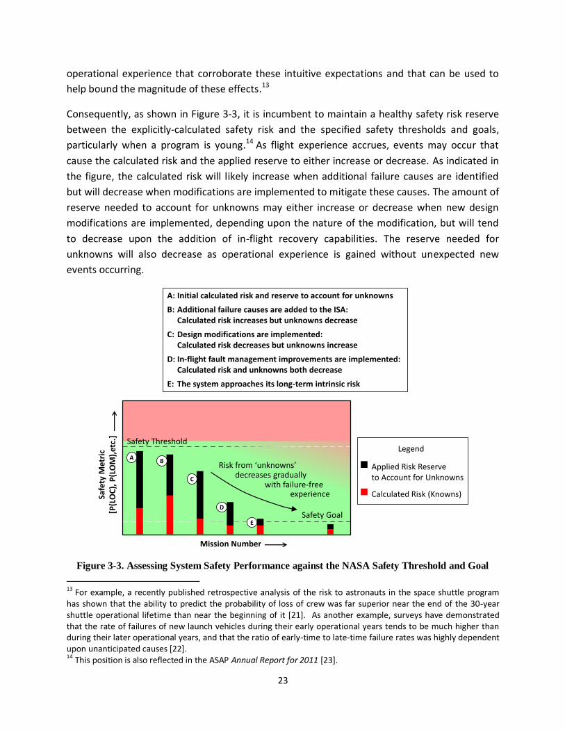
23
operational experience that corroborate these intuitive expectations and that can be used to
help bound the magnitude of these effects.13
Consequently, as shown in Figure 3-3, it is incumbent to maintain a healthy safety risk reserve
between the explicitly-calculated safety risk and the specified safety thresholds and goals,
particularly when a program is young.14 As flight experience accrues, events may occur that
cause the calculated risk and the applied reserve to either increase or decrease. As indicated in
the figure, the calculated risk will likely increase when additional failure causes are identified
but will decrease when modifications are implemented to mitigate these causes. The amount of
reserve needed to account for unknowns may either increase or decrease when new design
modifications are implemented, depending upon the nature of the modification, but will tend
to decrease upon the addition of in-flight recovery capabilities. The reserve needed for
unknowns will also decrease as operational experience is gained without unexpected new
events occurring.
Figure 3-3. Assessing System Safety Performance against the NASA Safety Threshold and Goal
13 For example, a recently published retrospective analysis of the risk to astronauts in the space shuttle program has shown that the ability to predict the probability of loss of crew was far superior near the end of the 30-year shuttle operational lifetime than near the beginning of it [21]. As another example, surveys have demonstrated that the rate of failures of new launch vehicles during their early operational years tends to be much higher than during their later operational years, and that the ratio of early-time to late-time failure rates was highly dependent upon unanticipated causes [22]. 14 This position is also reflected in the ASAP Annual Report for 2011 [23].
Safety Threshold
Safety Goal
Mission Number
Safe
ty M
etri
c[P
(LO
C),
P(L
OM
),et
c.]
Legend
Applied Risk Reserveto Account for Unknowns
Calculated Risk (Knowns)
Risk from ‘unknowns’
D
A: Initial calculated risk and reserve to account for unknowns
B: Additional failure causes are added to the ISA:Calculated risk increases but unknowns decrease
C: Design modifications are implemented:Calculated risk decreases but unknowns increase
D: In-flight fault management improvements are implemented:Calculated risk and unknowns both decrease
E: The system approaches its long-term intrinsic risk
E
decreases graduallywith failure-free
experience

24
Volume 2 will further elaborate on the subject of safety risk reserves and will provide guidance
on how to implement them with appropriate examples.
3.1.2 Being as Safe as Reasonably Practicable
An adequately safe system is as safe as reasonably practicable (ASARP). At the core of ASARP is
the concept of “reasonably practicable.” This entails weighing the safety performance of the
system against the sacrifice needed to further improve it. The system is ASARP if an incremental
improvement in safety would require a disproportionate deterioration of system operational
effectiveness, schedule, or cost. Thus, a system that is ASARP is one where safety improvement
is given the highest priority within program constraints, throughout all phases of the system life
cycle.
The ASARP concept is closely related to the “as low as reasonably achievable” (ALARA) and “as
low as reasonably practicable” (ALARP) concepts that are common in U.S. nuclear applications
and U.K. Health and Safety law, respectively. The terms ALARA and ALARP refer to ‘risk’ as that
term is used in these contexts, and is therefore something to be minimized. Because the term
‘risk’ is used in NPR 8000.4A as “the potential for performance shortfalls… with respect to
achieving explicitly established and stated performance requirements,” which is not the context
in which the term is used in the ALARA and ALARP concepts, ASARP refers instead to
maximizing safety instead of minimizing risk. Nevertheless, the terms are essentially
synonymous.
ALARA is defined in 10 CFR 20 [9] as:
“…making every reasonable effort to maintain exposures to ionizing radiation as
far below the dose limits as practical, consistent with the purpose for which the
licensed activity is undertaken, taking into account the state of technology, the
economics of improvements in relation to state of technology, the economics of
improvements in relation to benefits to the public health and safety, and other
societal and socioeconomic considerations, and in relation to utilization of
nuclear energy and licensed materials in the public interest.”
Similarly, the definition of ALARP set out by the British Court of Appeal [24] is:
“‘Reasonably practicable’ is a narrower term than ‘physically possible’ … a
computation must be made by the owner in which the quantum of risk is placed
on one scale and the sacrifice involved in the measures necessary for averting
the risk (whether in money, time or trouble) is placed in the other, and that, if it
be shown that there is a gross disproportion between them – the risk being

25
insignificant in relation to the sacrifice – the defendants discharge the onus on
them.”
Thus, the claim that a system is ASARP implies that:
A comprehensive spectrum of alternative means for achieving operational objectives
has been identified.
The performance of each alternative has been characterized in sufficient detail to
support an assessment of the relative gains and losses in performance (operational
effectiveness, safety, cost, and schedule) that would result from selecting one
alternative over another.
Safety performance is given priority in the selection of an alternative, insofar as the
selection is within operational constraints.
In other words, ASARP is an attitude towards risk-informed decision making (RIDM) [6] that
places a high value on safety. It is operative in every systems engineering process where
decisions are made that affect the safety performance of the system.
The ASARP concept is illustrated graphically in Figure 3-4. The curve represents the efficient
frontier15 of the trade space of identified alternatives, and shows the tradeoff between safety
performance and performance in other mission execution domains (cost, schedule, technical).
The ASARP region contains those alternatives whose safety performance is as high as can be
achieved without resulting in intolerable performance in one or more of the other domains.
Figure 3-4 shows that:
Improvements to cost, schedule, or technical performance beyond minimum tolerable
levels are not justifiable if they come at the expense of safety performance.16
The ASARP concept makes no explicit reference to the absolute value of a system’s
safety performance or the tolerability of that performance. It is strictly concerned with
its safety performance relative to that of the other identified alternatives.
ASARP is a region of the trade space and can contain more than one specific alternative.
Moreover, the boundaries of that region are not sharply defined. Consequently, there is
15 The efficient frontier represents the subset of the trade space containing those alternatives whose performance is not dominated by other alternatives. An alternative is dominated if there another alternative with superior performance in every performance measure. The efficient frontier expresses the limits of the functional relationships among the performance measures. At the efficient frontier, additional gains cannot be made in any performance measure without a concomitant erosion of performance in some other measure. 16 ASARP does not rule out improvements in cost, schedule, or technical performance that can be made without significant impact on safety.
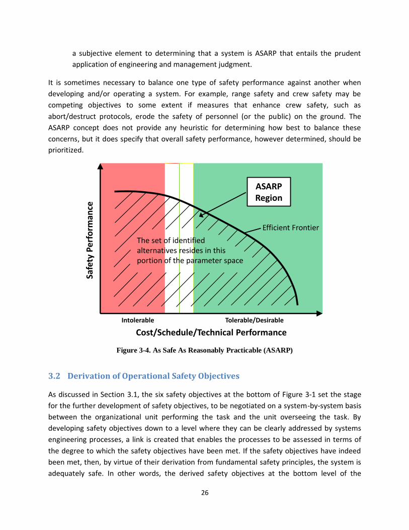
26
a subjective element to determining that a system is ASARP that entails the prudent
application of engineering and management judgment.
It is sometimes necessary to balance one type of safety performance against another when
developing and/or operating a system. For example, range safety and crew safety may be
competing objectives to some extent if measures that enhance crew safety, such as
abort/destruct protocols, erode the safety of personnel (or the public) on the ground. The
ASARP concept does not provide any heuristic for determining how best to balance these
concerns, but it does specify that overall safety performance, however determined, should be
prioritized.
Figure 3-4. As Safe As Reasonably Practicable (ASARP)
3.2 Derivation of Operational Safety Objectives
As discussed in Section 3.1, the six safety objectives at the bottom of Figure 3-1 set the stage
for the further development of safety objectives, to be negotiated on a system-by-system basis
between the organizational unit performing the task and the unit overseeing the task. By
developing safety objectives down to a level where they can be clearly addressed by systems
engineering processes, a link is created that enables the processes to be assessed in terms of
the degree to which the safety objectives have been met. If the safety objectives have indeed
been met, then, by virtue of their derivation from fundamental safety principles, the system is
adequately safe. In other words, the derived safety objectives at the bottom level of the
Safe
ty P
erf
orm
ance
Cost/Schedule/Technical Performance
Intolerable Tolerable/Desirable
ASARP Region
The set of identified alternatives resides in this portion of the parameter space
Efficient Frontier

27
objectives hierarchy represent the operational definition of safety for the system under
consideration, and are therefore referred to as operational safety objectives.17 As such, they are
the starting point for tailoring the systems engineering processes used in design, realization,
and operation, to assure that they adequately address safety in every activity that has the
potential to affect safety.
Although there is expected to be a high degree of overlap between the operational safety
objectives of different aerospace systems, due in part to the application of a common NASA
systems engineering framework across the agency, there is no single set of operational safety
objectives that is universally applicable to all systems. Factors that influence their development
include:
The presence of members of the public (or lack thereof)
The presence of crew (or lack thereof)
The presence and type of environmental hazards (Earth environment, planetary
environment)
Expectations of post-mission system recovery/reuse
System cost
System life expectancy
Mission value
The level in the product breakdown structure (PBS) under consideration (e.g., vehicle,
element, system, sub-system)
The systems engineering process framework used
In any case, the rationale for a given decomposition from fundamental safety principles to
operational safety objectives must be given (e.g., in the System Safety Technical Plan (SSTP)
[1]), with specific emphasis on the completeness of the derivation.
Figure 3-5 presents an example derivation of operational safety objectives for a notional space
mission. They fall within the four areas illustrated by the shaded boxes, “The quantified safety
performance meets requirements,” “Decisions are risk informed,” “Requirements that affect
17 The term ‘operational’ is used here to indicate that these are the objectives that the system safety activities explicitly address. It is unrelated to the usage of the term ‘operation’ in the context of ‘system design, realization, and operation.’

28
Figure 3-5. Derivation of Operational Safety Objectives for a Notional Space Mission
Decisions are risk
informed
Requirements that affect
safety are complied with
Unknown and un-
quantified safety hazards
are managed
The quantified safety performance
meets requirements
Achieve an
adequately safe
system
Achieve a system that
meets or exceeds the
minimum tolerable level
of safety
Achieve a system that
is as safe as
reasonably practicable
(ASARP)
Build the system to
meet or exceed the
minimum tolerable level
of safety
Operate the system to
continuously meet or
exceed the minimum
tolerable level of safety
Design the system to
be as safe as
reasonably practicable
Build the system to be
as safe as reasonably
practicable
Operate the system to
continuously be as safe
as reasonably
practicable
Incorporate appropriate
historically-informed
defenses against
unknown and un-
quantified safety
hazards into the design
Be responsive to new
information during
system realization
Risk inform decisions
during system
operation
Allocate requirements
consistent with
achievable safety
performance
Be responsive to new
information during
system operation
Minimize the
introduction of
potentially adverse
conditions during
system realization
Design the system to
meet or exceed the
minimum tolerable level
of safety
Risk inform design
solution decisionis
Comply with levied
requirements that affect
safety
Maintain compliance
with levied
requirements that affect
safety
Risk inform decisions
during system
realization
Minimize the
introduction of
potentially adverse
conditions during
system operation
Operational
Safety
Objectives

29
safety are complied with,” and “Unknown and un-quantified safety hazards are managed.” The
processes used to achieve these objectives is the topic of Section 4, System Safety Activities.
3.2.1 The Quantified Safety Performance Meets Requirements
In practice, the extent to which a system meets minimum tolerable levels of aggregate safety is
assessed in terms of meeting levied safety performance requirements that either directly
correspond to minimum tolerable levels or are allocated from safety performance
requirements from the organizational unit above. No additional decomposition is needed in this
area to arrive at the operational objectives of:
Design the system to meet or exceed the minimum tolerable level of safety.
Build the system to meet or exceed the minimum tolerable level of safety.
Operate the system to continuously meet or exceed the minimum tolerable level of
safety.
Implicit in these objectives is a safety analysis whose performance measures correspond to the
safety performance of interest, and that is conducted in accordance with the analysis protocols
that have been agreed on as part of the requirements negotiation process between the
responsible organizational units. As such, issues such as the completeness of the set of analyzed
accident scenarios, the effectiveness of controls, and the likelihood of adverse safety
consequences, are subsumed within the conduct of the safety analysis.
3.2.2 Decisions are Risk Informed
As discussed in Section 3.1.2, the ASARP concept implies risk-informed decision making (RIDM)
throughout the system life cycle. RIDM is discussed in detail in [6], and contains the steps
enumerated in Figure 3-6. In RIDM, safety analysis is integrated into a risk analysis framework,
illustrated in Figure 3-7, in order to supply inputs to other mission execution domain analyses
(cost, schedule, technical) whose results are dependent upon the safety analysis results, and to
produce the safety performance measures that bear upon stakeholder objectives and are
therefore relevant to decision making. This enables decision alternatives to be compared in
terms of the full spectrum of performance characteristics that matter to the decision maker,
which is a necessary condition for assuring that the system is ASARP.
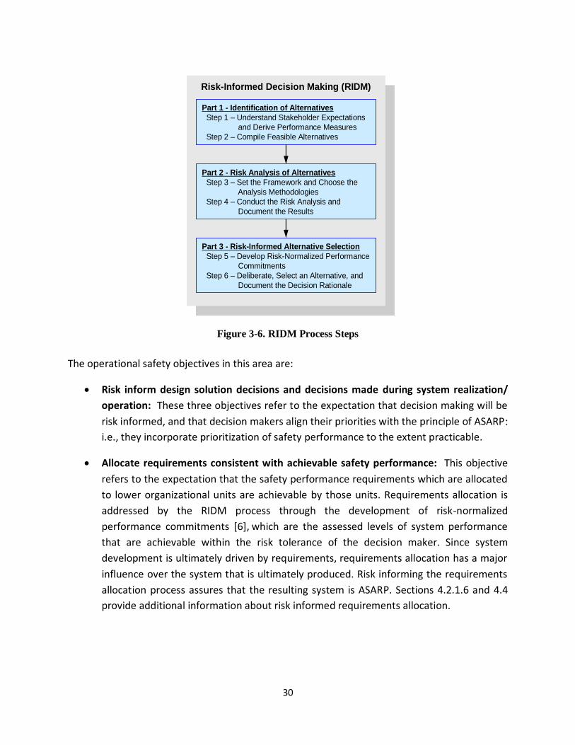
30
Figure 3-6. RIDM Process Steps
The operational safety objectives in this area are:
Risk inform design solution decisions and decisions made during system realization/
operation: These three objectives refer to the expectation that decision making will be
risk informed, and that decision makers align their priorities with the principle of ASARP:
i.e., they incorporate prioritization of safety performance to the extent practicable.
Allocate requirements consistent with achievable safety performance: This objective
refers to the expectation that the safety performance requirements which are allocated
to lower organizational units are achievable by those units. Requirements allocation is
addressed by the RIDM process through the development of risk-normalized
performance commitments [6], which are the assessed levels of system performance
that are achievable within the risk tolerance of the decision maker. Since system
development is ultimately driven by requirements, requirements allocation has a major
influence over the system that is ultimately produced. Risk informing the requirements
allocation process assures that the resulting system is ASARP. Sections 4.2.1.6 and 4.4
provide additional information about risk informed requirements allocation.
Risk-Informed Decision Making (RIDM)
Part 1 - Identification of Alternatives
Step 1 – Understand Stakeholder Expectations
and Derive Performance Measures
Step 2 – Compile Feasible Alternatives
Part 2 - Risk Analysis of Alternatives
Step 3 – Set the Framework and Choose the
Analysis Methodologies
Step 4 – Conduct the Risk Analysis and
Document the Results
Part 3 - Risk-Informed Alternative Selection
Step 5 – Develop Risk-Normalized Performance
Commitments
Step 6 – Deliberate, Select an Alternative, and
Document the Decision Rationale
To Requirements (Re)Baselining

31
Figure 3-7. Safety Analysis in the Context of the RIDM Risk Analysis Framework
Be responsive to new information during system realization/operation: These
objectives refer to the expectation that system management will be responsive to new
information that arises post-design. The information itself can be either positive (a
potential opportunity) or negative (a potential concern), and can come from within the
system (e.g., anomalous system behavior) or from sources external to the system (e.g.,
investigations of similar systems, changes to the system’s operating environment). In
any case, the expectation is that a RM capability will be implemented that will enable
system design and operational modifications to be considered in light of new
information, so that unnecessary deterioration of safety can be averted and that
opportunities to improve safety can be exploited.
3.2.3 Requirements that Affect Safety are Complied With
Requirements represent the constraints placed upon the system. In the hierarchical structure of
NASA, organizational units generally interact with requirements in two distinct ways: by
complying with requirements that have been negotiated with the next higher organizational

32
unit in the hierarchy; and by overseeing compliance with requirements that have been
negotiated with organizational units at lower levels of the hierarchy.
Allocate requirements consistent with achievable safety performance: This objective
is in this section, as well as in Section 3.2.2, because the organizational unit that
allocates requirements to lower level units is also responsible for overseeing compliance
with the allocated requirements.
Comply/maintain compliance with levied requirements that affect safety: These
objectives refer to the basic systems engineering expectation that requirements will be
complied with, and that compliance will be maintained throughout the system life cycle.
3.2.4 Unknown and Un-quantified Safety Hazards are Managed
The area, ‘Decisions are Risk Informed,’ addresses those accident scenarios whose impacts on
safety performance have been quantified. However, in all safety analysis activities there is the
issue of completeness, i.e., there is no way to ensure that all scenarios (above some threshold
of significance) have been appropriately identified and analyzed. There is always the possibility
of the existence of unknown and un-quantified safety hazards, which are typically managed
using a suite of heuristic best practices such as simplicity in design, robust margins, adherence
to codes and standards, inclusion of recovery capability, etc.
Incorporate appropriate historically-informed defenses against unknown and un-
quantified safety hazards into the design: This objective refers to measures taken to
minimize the possibility that an incomplete understanding or analytical characterization
of the system will result in a system that may exhibit undesirable safety performance.
These measures go beyond those explicitly derived from the ISA, to include measures
that have developed historically and are recognized as best practices in their
engineering disciplines. Defenses against unknown and un-quantified safety hazards
represent a historically-informed conservative stance with respect to incomplete
understanding of the system.
Minimize the introduction of potentially adverse conditions during system
realization/operation: These objectives refer to the expectation that the system will be
built, operated, and maintained in such a way as to minimize the introduction of
additional hazards. Such hazards may be introduced as a result of manufacturing or
integration processes, life cycle maintenance practices, operational practices, etc. In
general, this area relates to adherence to best practices in system realization and
operation, and the imposition of engineering discipline to keep system operation within
the design intent.

33
4 System Safety Activities
4.1 Introduction
In Chapter 3, an example safety objective hierarchy was devised with separate derivative
objectives applying to each of three phases during the life cycle: design, realization, and
operation. When talking about system safety activities and their relationships to the safety
objectives, it is convenient to decompose the design phase still further into two sub-phases
because the activities during early design tend to be quite different from those during later
design. This is to be expected from the fact that early design decisions, which involve choices
between basic concepts, are informed by risk-informed decision making (RIDM) processes,
whereas later design decisions, which are of a more detailed nature, are informed by
continuous risk management (CRM) processes. Thus, this chapter on system safety activities
will provide separate examples for each of the following four mission phases:
Concept development and early system design
Detailed system design
System realization
System operation (including performance monitoring and re-evaluation)
Section 4.2 will deal with the characterization of the system safety activities and the
development of the relationships between them and the safety objectives. Sections 4.3 through
4.5 will discuss special topics that are important for the successful execution of the activities
within the frameworks provided by NPR 7123.1 and NPR 8000.4A. Section 4.3 will be concerned
with topics relevant to integrated safety analysis, Section 4.4 with topics relevant to risk-
informed allocations of safety thresholds and goals, and Section 4.5 with topics relevant to the
collaborative formulation of controls.
The development of the risk-informed safety case, which provides the arguments that the
safety objectives have been met, will be provided in Chapter 5.
4.2 Overview of System Safety Activities and their Relationships to Safety
Objectives
4.2.1 Concept Development and Early System Design
The system safety activities needed to support concept development and early system design
are presented in Figure 4-1 in purple colored boxes. The operational safety objectives for this

34
phase, in blue colored boxes, are those listed in Figure 3-5 of Section 3.2 in conjunction with the
blocks that start with the phrase “Design the system to ...”.
A bit of orientation is needed to facilitate understanding of Figure 4-1 and the figures that
follow. First, note that the activities in several of the purple boxes are nested. For example, the
box entitled “Develop Integrated Safety Analysis (ISA)” is wholly contained within a box entitled
“Develop Risk Analysis of Alternatives”. This nesting purports to show that integrated safety
analyses are part of a risk analysis process that also includes other contributing activities: cost
analysis, schedule analysis, and technical performance analysis in particular. These other
analysis activities are germane to the system safety formulation because they contribute to the
evaluation of whether the system is “As Safe as Reasonably Practicable”, one of the governing
safety objectives. Thus, although they are not performed by system safety professionals, they
are explicitly shown in a figure entitled “Principal System Safety Activities”. The box entitled
“Develop Risk Analysis of Alternatives” is likewise contained within a box entitled “Conduct
RIDM”. The RIDM box includes not only risk analysis but also other contributing activities (such
as deliberation on decisions; Refer to Figure 3-6). However, since these other contributing
activities are not part of the safety framework, they are not explicitly shown in the figure. The
nesting format automatically implies an arrow from the smaller activities within the nest to the
larger activity surrounding it.
The arrows that are in the form of arcs depict two separate types of interfaces. One is the
input-output relationships between the activities, and the other is the principal interfaces
between the activities and the objectives. In the interest of avoiding excessive clutter,
interfaces between activities and objectives that are considered to be secondary are not
shown. Some of the more important interfaces will be discussed in succeeding subsections.
Between the activities and the objectives is a horizontal broad olive-colored arrow labeled
“RISC”, within which lies the Risk Informed Safety Case. Although not explicitly shown in this
figure and those that follow, the RISC arrow contains the case to be made that the evidence
produced by the system safety activities is sufficient to justify that the safety objectives have
been met. The contents of the RISC arrow will be the principal topic to be discussed in Chapter
5.
The following subsections will discuss the nature of each of the system safety activities that are
depicted in Figure 4-1.

35
Figure 4-1. Principal System Safety Activities and Related Processes during Concept Development and Early System Design, and their
Interfaces with the Safety Objectives
Conduct RIDM(analytic deliberative process)
RISCRISC Evaluation
Confirms Safety
Develop risk analyses of alternatives
Design a safe system
during early design
Design the system to meet
or exceed the minimum
tolerable level of safety
Design the system to be
as safe as reasonably
practicable
Risk-inform
design solution
decisions
Allocate requirements
consistent with
achievable safety
performance
Incorporate appropriate
historically-informed defenses
against unknown and un-quantified
safety hazards into the design
Develop ISAs
(scenario-based
assessments of
hazards and
controls)
Develop other
mission execution
domain
performance
models
Set initial constraints
Compliance with tailored set of historically informed
requirements, standards,
and best practices
Allocate requirements using
performance
commitments
Sa
fety
Ea
rly
De
sig
n O
bje
cti
ve
sS
ys
tem
Sa
fety
Ac
tiv
itie
s
(wit
hin
Sy
ste
ms
En
gin
ee
rin
g)
Select a design solution for implementation
Consider
system
realization
and operation
phases
Formulate
risk
management
plan
Conduct CRM Initialization
Applicable
safety
require-
ments
Design
alterna-
tives
Risk
toler-
ances
Note: See Section 4.2.1 for an explanation of the use of nesting and curved arrows to highlight significant relationships and interfaces.

36
4.2.1.1 Set Initial Constraints
The initial constraints are developed within the system safety function in collaboration with the
systems engineering function and the project stakeholders and decision makers. At the
beginning of a project during concept development, the requisite constraints include the
following:
Conceptual characterization of the design alternatives being considered.
Applicable requirements and standards developed or adopted for the project by the
system engineering function. Initially the emphasis is on requirements that pertain to
safety, but because one of the high level objectives is to develop a system that is as safe
as reasonably practicable (ASARP), the safety analysts also have to be aware of the key
requirements that pertain to cost, schedule and technical performance.
The decision makers’ risk tolerance levels for not meeting the requirements. Risk
tolerance is usually expressed as the amount of uncertainty that the decision maker is
willing to tolerate pursuant to meeting the requirement. Since requirements are
specified by systems engineering and risk tolerances by decision makers, the two are
considered separate entities.
Other mission-relevant constraints, including concept of operations, design reference
missions, and operating environments.
The constraints affect many of the activities, although the arrow in Figure 4-1 indicates that the
principal effect is on the activities contained within the general context of risk informed
decision making.
4.2.1.2 Conduct Risk-Informed Decision Making
The principal objectives of RIDM are as follows:
Provide and explain risk results to decision makers in order to facilitate their decisions
about which of several major design alternatives to select for further development.
Provide performance commitments and associated risk tolerances to the system
engineering function to facilitate the development of performance requirements for the
selected design alternative.
Assist in the allocation of safety-related performance requirements from higher to
lower levels in the organization.

37
In addition to these general objectives, there are specific products and information that RIDM
provides to support the system safety activities:
Models and results that the system safety team can use to evaluate trade-offs in the
search for a final design that is “as safe as reasonably practicable”
The general RIDM process includes risk-informed decision making spanning all four mission
execution domains: safety, technical, cost, and schedule. Although the integration of risk
models from these four domains is the responsibility of the risk management (RM) function,
the development of individual models that support this integration effort requires interaction
of the RM analysts with the analysts that are dedicated to modeling system safety, technical
performance, cost, and schedule. Therefore, although RIDM has its own framework and
processes (as summarized in [6]), there are strong interfaces with the system safety framework
and, correspondingly, the results pertaining to safety, technical, cost, and schedule risks are
shared.
4.2.1.2.1 Develop Integrated Safety Analyses
The integrated safety analysis (ISA) during concept development and early design occurs under
the RIDM process, and in later phases occurs under the CRM process.18 ISA is a proactive
investigation into the ways that the system can fail, the likelihood of such failures, and their
consequences. ISA includes both hazard-centric and non-hazard-centric methods for identifying
and characterizing potential accident scenarios. This includes accident causes, contributing
factors, effectiveness of controls (both existing and proposed), analysis of physical responses of
the system to the environments it encounters, and analysis of the probability that the
undesirable consequences will be realized. Both quantitative and qualitative analyses can be
performed as part of an ISA, as appropriate for the scenario being considered and the nature of
the undesired consequence. Principal outputs from ISA are as follows:
A set of accident scenarios that can produce undesirable safety performance (see
Appendix B and Section 4.3.1 for a definition and discussion of the term “scenario”)
Identification and evaluation of the potential causes of these accident scenarios
Identification and evaluation of existing controls associated with the scenarios
Probability density functions (PDFs) for safety metrics when appropriate (e.g., PDFs for
the probability of LOC, LOV, LOM.)
18 As mentioned in an earlier footnote, ISA is different from the Integrated Design and Safety Analysis function referred to in other documents with reference to failure tolerance and redundancy requirements.

38
Safety margins (e.g., structural and thermal safety margins, radiation margins, etc.)
Sensitivity of safety metric PDFs and safety margins to parameter variations
Credibility assessment of the models used
The safety analysis should have the following characteristics (which will be elaborated upon
further in Section 4.3):
PDFs for safety metrics and safety margins should be obtained for all key decision points
(KDPs) during the project, including those that have not yet occurred. In other words,
the safety analyses should consider time to be a variable and should clarify how the risk
is anticipated to increase or decrease between the present time and the completion of
the project.
The analysis models should be scenario based. It is not sufficient simply to identify
hazards and formulate controls. Rather, a set of possible accident scenarios should be
developed wherein each scenario starts from an initiating event, proceeds with the
occurrence of enabling events, and terminates with consequences that pertain to not
meeting safety requirements.
A graded analysis approach should be used. That is to say, the amount of effort spent in
evaluating each scenario (i.e., formulating the models, obtaining supporting data, and
performing calculations) should be proportional to the risk-importance of the scenario.
Uncertainties should be explicitly considered. The risk evaluation should include both
aleatory uncertainty (pertaining to random or stochastic behavior) and epistemic
uncertainty (pertaining to lack of knowledge). Where possible, these two types of
uncertainty should be analyzed separately from one another. Uncertainties to be
addressed should include both uncertainties in input parameters to the models and
uncertainties in the models used.
There should be evidence, per NASA-STD-7009, Standard for Models and Simulations
[25], that the models and the data used as input to them are technically credible and
appropriate for the conditions under which they are assumed to apply.
4.2.1.2.2 Develop Other Mission Execution Domain Performance Models
Because of the “reasonably practicable” part of the ASARP objective, it is necessary to consider
the cost, schedule, and technical performance impacts of various options being considered to
optimize safety. Modeling of cost, schedule, and technical performance per se is not a
responsibility of the system safety function, but is rather under the jurisdiction of other
39
organizational units within the project. However, under the ASARP objective, the system safety
function requires involvement in the systems engineering trade studies that consider how
variations in design, test plans, sustainment, and other facets of the project might affect not
only safety but also the other mission execution domains. This requires that the safety team
work closely with the costing, scheduling, and engineering units within the project.
4.2.1.3 Select a Design Solution for Implementation
The process of down-selecting from the design alternatives to one particular design concept is
conducted through a risk-informed deliberation by the decision makers. The safety team
collaborates in ensuring that results from the integrated safety analysis are understood and
properly interpreted by the decision makers.
Although the integrated safety analysis and overarching RIDM activities described in this
section are conducted during the concept development and early design phase, the risks being
considered must include not only design risks but also risks during the system realization and
operation phases that may be instigated or promoted by the design being considered.
Therefore, the risk information provided to the decision makers includes risks that may come to
realization in future mission phases, not just the present mission phase.
The selection of a design concept is documented in a Risk Informed Selection Report and is
incorporated into the project’s Risk Management Plan (RMP).
4.2.1.4 Conduct CRM Initialization
As discussed in the RM Handbook [6], the role of CRM early in the project, before most design
details have been developed, is to complete the risk modeling started during RIDM to include
all scenarios that affect the magnitude of the performance risks (as opposed to emphasizing
just those that are needed to differentiate between the candidate design alternatives).
Therefore, the CRM initialization activity provides improved models and results that the system
safety team can use to better evaluate ASARP trade-offs and tailor the safety requirements.
Another outcome from CRM initialization is a more complete identification of the scenarios
that are driving the risk. Once known, it may be decided that a more detailed and robust
treatment of these risk-driving scenarios is needed in order to ensure the accuracy and
completeness of the analysis. Similarly, it may be possible to lessen the amount of robustness
applied to scenarios that are not contributing significantly to risk, or even to drop them from
the model altogether, so as to reduce downstream analysis costs. This is the essence of a
graded approach, which allows for the integrated safety analysis to be tailored so that effort is

40
dedicated foremost to the scenarios that matter. The feedback path from CRM initialization to
Integrated Safety Analysis in Figure 4-1 provides this mechanism.
4.2.1.5 Comply with a Tailored Set of Historically Informed Requirements,
Standards, and Best Practices
Requirements that have developed historically and are recognized as best practices in their
engineering disciplines tend to provide protection against potential accident scenarios that may
not have been uncovered during the risk assessment or that may have been uncovered but are
not easily quantified. Therefore, compliance with such requirements helps to achieve the
objective of incorporating defenses against unknown or un-quantified safety hazards.
At the same time, as part of the risk-informed process for decision making, requirements levied
upon an organizational unit may be appealed if it can be shown that they impede the
achievement of optimal safety rather than facilitate it. Justification for appealing requirements
is provided in NASA Policy Directive NPD 1000.0A, Governance and Strategic Management
Handbook [26], from which the following is a direct quotation:
“Good requirements that are properly managed are essential to any successful
undertaking. Part of establishing the proper set of requirements is the adjustment of
prescribed requirements to the specific task (e.g., a program or project).
“Principals that govern processes of tailoring requirements are:
1. “The organization at the level that established the requirement must approve the
request for tailoring of that requirement unless this authority has been formally
delegated elsewhere. The organization approving the tailoring disposition consults
with the other organizations that were involved in the establishment of the specific
requirement and obtains concurrence of those organizations having a material
interest.
2. “The involved management at the next higher level is to be informed in a timely
manner of the request for tailoring of the prescribed requirements.”
In the process for tailoring the set of requirements that is deemed to be applicable to a
program or project, individual requirements are either waived or adjusted. Waiving of a
requirement involves an excision of the requirement in its entirety from the set that applies to
the program/project. Adjustment of a requirement implies that the requirement remains in
place but in an altered form. For example, if the requirement specifies a threshold value that
must be achieved within a given risk tolerance, the adjustment may involve a change to the
threshold value, the associated risk tolerance, or both.

41
System safety enters into the deliberation of whether or not a requirement should be waived or
adjusted by providing the risk information that supports the decision. For example, either of the
following two arguments could be used in favor of waiving a requirement:
The requirement clearly has a negative impact on safety (e.g., increases the probability
of LOC), and removing it would not have any negative impacts on other mission
execution domains (i.e., would not increase cost, cause schedule slippages, or degrade
technical performance).
The requirement has only a negligible positive effect on safety and removing it would
have a clearly significant positive effect on or more other mission execution domains.
An argument that might be used to support adjustment of a requirement, rather than waiving
it, might be as follows:
Making a prescribed adjustment to the requirement would have a clearly significant net
positive effect on safety and clearly would not have a significant negative impact on the
other mission execution domains.
The use of the term “clearly” in each of these arguments states a desire that the decision to
waive or adjust a requirement be made judiciously and only when clearly indicated as
beneficial. The reason for this caution is that the requirements, when initially formulated, may
have been based on best practices derived from historical experience, or on other
considerations that go beyond safety. Discarding or adjusting requirements should not be
undertaken without careful deliberation of the concomitant effects, which might include the
following:
Impacts on the overall safety defense strategy (e.g., a degradation of a defense-in-
depth strategy)
Impacts on the Agency’s strategic goals
Impacts on perceptions outside the Agency
In other words, the decision to waive or adjust requirements, like any key decision, should be
risk-informed but not risk-based.
4.2.1.6 Allocate Requirements using Performance Commitments
In order for a design team at any level of the organization to complete its work, it is necessary
for it to have requirements for the performance of the assets that it is responsible for. The
process for determining the required asset performance parameters involves an allocation, e.g.,

42
from system to subsystem or component level. (Note that although allocation is most
commonly thought of in terms of reliabilities, any quantitative performance requirement can be
allocated.)
In theory, the required performance at subsystem or component level should result in the
performance of the system being at least as high as its required value. For example, allocated
mean failure rates at subsystem or component levels should be both practical and consistent
with achieving the thresholds and goals for the probabilities of LOC, LOV, and LOM at the
system level. The problem is that there is a high risk of not meeting these criteria and of not
achieving the ASARP objective if the allocation is performed in an ad-hoc manner, where
historical experience is the only guide. For this reason, it is important that the allocation
process be model based and risk informed. The RIDM and CRM initialization processes provide
a basis for accomplishing this since, taken together, they provide support for the development
of performance commitments and risk tolerances that relate to the performance objectives of
each organizational unit.
More on this subject will be provided in Section 4.4.
4.2.2 Detailed System Design
The system safety activities needed to support detailed system design are presented in Figure
4-2. This phase is different from the concept development and early design phase because the
length of time required to complete the detailed design makes it likely that new risk issues
requiring resolution will surface as design details are being developed. These new risks often
involve the necessity of having to reallocate subsystem masses while ensuring that allocated
safety requirements, codes, and standards continue to be satisfied.
The lower level safety objectives for this phase consist of a combination of objectives listed in
Figure 3-5 of Section 3.2 under the phrases “Design the system to ...” and “Build the system to
...”. This results in an expansion lower-level objectives under the ASARP objective to five, as
shown in Figure 4-2. The broadening of the early design safety objectives reflects the fact that
during detailed design, new information, both positive and negative in character, is being
generated. Sometimes this information takes the form of new risks and challenges. Other times
the new information takes the form of new opportunities to improve safety.

43
Figure 4-2. Principal System Safety Activities and Related Processes during Detailed System Design, and their Interfaces with the Safety
Objectives
Conduct CRM (analytic deliberative process)Also conduct RIDM if major re-planning is needed
Maintain risk analysis of system
performance
Program control & commitments
Design a safe system
during detailed design
Design the system to
meet or exceed the
minimum tolerable
level of safety
Design the system to be
as safe as reasonably
practicable
Maintain
integrated
safety
analysis
Maintain other
mission exe-
cution domain
performance
models
Be responsive
to new
information
during system
design
Sa
fety
De
taile
d D
es
ign
Ob
jec
tiv
es
Sy
ste
m S
afe
ty A
cti
vit
ies
(wit
hin
Sy
ste
ms
En
gin
ee
rin
g)
RISC RISC Evaluation
Confirms Safety
Minimize the
introduction of
potentially
adverse
conditions during
system design
Comply with
levied
requirements
that affect
safety
Conduct
research
and
testing
programs
Implement
communication
protocols,
configuration
management,
design best
practices,
lessons
learned, etc.
Conduct
verification
and validation
that safety
requirements
are being met
Risk-inform
design
solution
decisions
Management
proactively
seeks net-
beneficial
safety
improvements
Control
identified
individual
risks
Maintain
allocation of
requirements
consistent with
achievable safety
performance
Note: See Section 4.2.1 for an explanation of the use of nesting and curved arrows to highlight significant relationships and interfaces.

44
4.2.2.1 Conduct Continuous Risk Management (CRM) during Detailed System Design
The gathering of new information that affects the risks in any of the mission execution domains
(safety, technical, schedule, and cost) is a role of CRM that is maintained throughout the entire
project timeline. This type of new information is used to update the risk models and supporting
databases. Consonant with these updates, the role of CRM evolves to include the development
and implementation of new controls when needed to counteract any new or changed risks. As
appropriate, the CRM activity includes research and testing in order to improve the
understanding of the risks and to assist the development of controls.
As is discussed in the RM Handbook [6], the activities conducted as part of CRM comprise the
following steps:
Identify: The purpose of the Identify step is to capture stakeholders’ concerns regarding
the achievement of safety requirements as well as performance requirements in other
mission execution domains. These concerns are recorded as individual risks in a risk
database. Each individual risk is articulated as a risk statement that contains a condition,
a departure, an asset, and a consequence.
Analyze: The objectives of the Analyze step are to estimate the likelihoods of the
departure and the magnitudes of the consequence for each individual risk, to evaluate
the timeframe available for preventive or mitigative action, to characterize the
uncertainties, to calculate the aggregate risks of not meeting specified thresholds and
goals at different project milestones (as well as the aggregate risks within other mission
execution domains), and to determine which departure events and parameters within
the models are the most important contributors to each aggregate risk (i.e., the drivers
for the risk of not meeting the requirement for P(LOC), P(LOV), P(LOM), and each other
levied safety requirement).
Plan: The objective of the Plan step is to decide what action, if any, should be taken to
reduce the safety risks and other mission execution domain risks that are caused by the
aggregation of identified individual risks. The possible actions are: Accept, Mitigate,
Watch, Research, Elevate, and Close.
Track: The objective of the Track step is to acquire, compile, and report observable
data to follow the progress of the implementation of risk management decisions, and
their effectiveness once implemented. The tracking task of CRM serves as a clearing
house for new information that could lead to a new risk item, a change in risk analysis, a
change in a previously agreed-to plan, or the need to implement a previously agreed-to
contingency.

45
Control: When tracking data indicates that a risk management decision is not impacting
risk as expected, it may be necessary to implement a control action. Control actions are
intended to assure that the planned action is effective. If the planned action becomes
unviable, due either to an inability to implement it or a lack of effectiveness, then the
Plan step is revisited and a different action is chosen
Communicate and Document: Well-defined, documented communication tools,
formats, and protocols assure that individual risks are identified in a manner that
supports the evaluation of their impacts on performance risk and that those that impact
multiple organizational units (i.e., crosscutting risks) are identified, enabling the
coordination of risk management efforts. Risk management decisions and their
rationales are captured as part of the institutional knowledge of the organization.
As was discussed with regard to the RIDM process, the development of individual models that
support the risk integration and management effort requires interaction of the RM analysts
with the analysts that are dedicated to modeling system safety, technical performance, cost,
and schedule. Therefore, although CRM, like RIDM, has its own processes (as summarized in
[6]), there are strong interfaces with the system safety framework. For example, any controls
developed within CRM to prevent or mitigate a new risk must support the following general
safety objectives:
Assure that the overall probabilistic safety threshold requirement continues to be
satisfied
Assure that safety performance continues to be the most important priority as long as
the impacts to cost, schedule, and technical performance remain acceptable
Assure that the approach to safety is holistic, such that the overall control strategy
promotes protection against unknown or un-quantified risks
4.2.2.2 Maintain a Robust Set of Program Controls and Commitments during Detailed
System Design
Program controls and commitments play an important role in ensuring that safety objectives
are met. During the detailed design phase, some of the more important elements of this
activity include the following:
Management actively promotes an environment within which design opportunities for
improving safety without incurring unreasonable cost, schedule, and technical impacts
are sought out and implemented.

46
Protocols are in place that promote effective and timely communication among design
teams from different organizations working on different parts of the system.
Configuration management processes are in place to ensure that modifications to the
design are kept up to date and that everyone is working from the same drawings and
specifications.
There is a process for ensuring that decisions relating to design choices are informed by
best practices and by lessons learned from previous projects; for example, mass margins
and safety margins are adequate and appropriate for each project milestone.
There is a process for verifying that all requirements, codes, and standards related to
system design that have been designated as being important to safety are satisfied, and
continue to be satisfied as changes occur.
Because of the ASARP principle that puts a premium on improving safety, there is a feedback
loop in Figure 4-2 from the block labeled “Management proactively seeks net-beneficial safety
improvements” to the block labeled “Conduct CRM”. The feedback involves tradeoffs wherein
variations in design variables and/or controls are explored. Sensitivity studies using the
integrated safety analysis models together with cost, schedule and technical performance
models are performed to determine how these variations affect the ability to meet
performance requirements in each mission execution domain. The ASARP process in general is
a collaborative effort involving deliberation between the system safety team and the teams
responsible for cost, schedule, and mission assurance.
Finally, just as the safety requirements for a program/project are tailored during early design by
using a risk-informed process, the formulation of program controls and commitments during
detailed design and subsequent phases similarly need to be tailored using a risk-informed
process. The intent is to focus attention and resources on risk-significant issues and on items
that are critical to safety, while defocusing attention and resources from insignificant issues and
noncritical items. The process is a deliberative one involving management and system safety
personnel.
4.2.3 System Realization
The system safety activities needed to support system realization are presented in Figure 4-3.
The safety objectives for this phase are those listed in Figure 3-5 of Section 3.2 in conjunction
with the blocks that start with the phrase “Build the system to ...”.

47
Figure 4-3. Principal System Safety Activities and Related Processes during System Realization, and their Interfaces with the Safety
Objectives
Conduct CRM (analytic deliberative process)Also conduct RIDM if major re-planning is needed
Maintain risk analysis of system
performance
Program control & commitments
Produce a safe
system
Build the system to
meet or exceed the
minimum tolerable
level of safety
Build the system to be
as safe as reasonably
practicable
Maintain
integrated
safety
analysis
Maintain
other mission
execution
domain
performance
models
Be responsive to
new information
during system
realization
Sa
fety
Re
aliza
tio
n O
bje
cti
ve
sS
ys
tem
Sa
fety
Ac
tiv
itie
s
(wit
hin
Sy
ste
ms
En
gin
ee
rin
g)
RISC RISC Evaluation
Confirms Safety
Minimize the
introduction of
potentially adverse
conditions during
system realization
Comply with levied
requirements that
affect safety
Conduct
research and
testing
programs
Implement
quality
assurance,
training,
procurement
best
practices,
lessons
learned, etc.
Conduct
verification
and
validation
that safety
requirements
are being met
Risk-inform
decisions during
system realization
Management
proactively
seeks net-
beneficial
safety
improvements
Control
identified
individual
risks
Note: See Section 4.2.1 for an explanation of the use of nesting and curved arrows to highlight significant relationships and interfaces.

48
4.2.3.1 Conduct Continuous Risk Management during System Realization
The activities under Continuous Risk Management and their interfaces with the safety
objectives during the system realization phase are similar to those in Section 4.2.2.1 and Figure
4-2.
4.2.3.2 Maintain a Robust Set of Program Controls and Commitments during System
Realization
During the system realization phase, some of the more important elements of program controls
and commitments include the following:
During the process of building the subsystems and integrating them into a completed
system, management actively promotes an environment within which opportunities are
sought out and implemented for improving safety without incurring unreasonable cost,
schedule, and technical impacts.
Quality assurance plans and processes are in compliance with SAE Aerospace Standard
(AS) 9100 [27], and audits and reviews are conducted to ensure that actual practice is in
compliance with the plans.
Training programs are in place where needed to help employees at NASA and NASA’s
suppliers to gain the necessary knowledge and skill to fulfill the mission. Where
appropriate, the personnel assigned to each task are certified to perform that task.
Best practices and lessons learned from previous programs and projects are
implemented into the activities conducted during the system realization phase.
The procurement process utilizes a risk-informed decision methodology to select
between supplier alternatives.
There is a process for verifying that all requirements, codes, and standards related to
system realization that have been designated as being important to safety are satisfied,
and continue to be satisfied as changes occur.
Effective processes for configuration management and change control are implemented
and maintained throughout the system realization phase.
Other aspects of program controls and commitments are discussed in Section 4.2.2.2.

49
4.2.4 System Operation
The system safety activities needed to support system operation are presented in Figure 4-4.
The safety objectives for this phase are those listed in Figure 3-5 of Section 3.2 in conjunction
with the blocks that start with the phrase “Operate the system to ...”.
4.2.4.1 Conduct Continuous Risk Management during System Operation
The activities under Continuous Risk Management and their interfaces with the safety
objectives during the system operation phase are similar to those in Section 4.2.2.1 and Figure
4-2. The exception is the deletion of the block entitled “Conduct Research and Testing
Programs”. Most research and testing to support a better understanding of the risks and
development of controls would have been completed prior to operation.
4.2.4.2 Maintain a Robust Set of Program Controls and Commitments during System
Operation
During the system operation phase, some of the more important elements of program controls
and commitments include the following:
During system operation, management actively promotes an environment within which
opportunities are sought out and implemented for improving safety without incurring
unreasonable cost, schedule, and technical impacts.
Unanticipated events and anomalies occurring during system operation are evaluated to
determine whether they could be considered as precursors to an accident. If so, this
information is fed back to the CRM process to determine whether the risk models need
to be modified and whether additional controls are needed.
A risk-informed approach to maintenance, inspections, and audits is implemented. The
ordering of activities in these areas is prioritized so that actions that are important to
safety risk are conducted first and most thoroughly.
Similarly, a risk-informed approach to training and certification of crew, mission control
personnel, and launch control personnel is implemented. Operating procedures,
training, and certification are prioritized to emphasize areas and skills that are needed
to minimize safety risks.
Best practices and lessons learned from previous programs and projects are
implemented into the activities conducted during the system operation phase.

50
Figure 4-4. Principal System Safety Activities and Related Processes during System Operation, and their Interfaces with the Safety
Objectives
Conduct CRM (analytic deliberative process)Also conduct RIDM if major re-planning is needed
Maintain risk analysis of system
performance
Program control & commitments
Operate a safe
system
Operate the system to
continuously meet or
exceed the minimum
tolerable level of safety
Operate the system to
continuously be as safe as
reasonably practicable
Maintain
integrated
safety
analysis
Maintain
other mission
execution
domain
performance
models
Be responsive to
new information
during system
operation
Sa
fety
Op
era
tio
n O
bje
cti
ve
sS
ys
tem
Sa
fety
Ac
tiv
itie
s
(wit
hin
Sy
ste
ms
En
gin
ee
rin
g)
RISCRISC Evaluation
Confirms Safety
Minimize the
introduction of
potentially adverse
conditions during
system operation
Maintain
compliance with
levied requirements
that affect safety
Control
identified
individual
risks
Conduct
performance
monitoring
including
accident
precursor
analysis
Implement risk-
informed
maintenance,
auditing,
inspections, crew
procedures, MCC
and LCC
procedures,
training and
certification, etc.
Risk-inform
decisions during
system operation
Management
proactively
seeks net-
beneficial
safety
improvements
Note: See Section 4.2.1 for an explanation of the use of nesting and curved arrows to highlight significant relationships and interfaces.

51
There is a process for verifying that all requirements, codes, and standards related to
system operation that have been designated as being important to safety are satisfied,
and continue to be satisfied as changes occur.
Effective processes for configuration management and change control are implemented
and maintained throughout the operational phase.
Other aspects of program controls and commitments are discussed in Section 4.2.2.2.
4.3 Special Topics Pertaining to Integrated Safety Analysis
This section provides a broader perspective and, in some cases, more detailed information on
themes that are discussed in Section 4.2 with regard to integrated safety analysis.
4.3.1 Scenario Orientation of System Safety Analysis
In realistic engineering situations, scenario-based modeling within ISA is central to building a
strong safety case, because it is necessary to understand what scenario elements need to be
prevented or mitigated, in order to formulate, justify, implement, and (for purposes of the
safety case) defend the strategies needed to prevent or mitigate those events. Moreover, in
typical system safety applications, besides identifying scenarios, it is necessary to quantify
scenario likelihoods, and to address uncertainty. This is true in the context of safety
prioritization and safety tradeoff exercises, or as part of addressing safety requirements, goals,
or thresholds.
In Figure 4-5, the concept of a “scenario” is used to define the safety context that will be
described in the RISC. As indicated in that figure, a scenario begins with an initiating event that
perturbs the system away from its nominal condition. Subsequent pivotal events that are
relevant to the evolution of the scenario may (or may not) occur, and may have either a
mitigating or exacerbating effect on the accident progression. The successful functioning of
controls will in general have a mitigating effect, whereas the failure of controls to function, the
defeating of controls due to overwhelming stresses, or the involvement of hazardous material
will tend to exacerbate the scenario. The spectrum of possibilities for the evolution of the
accident is represented by the multiple pathways that can be followed and the multiple end
states that can be produced.
As discussed in Section 2.2, both hazard-centric and non-hazard-centric analysis techniques
may be used to develop scenarios, identify risk drivers, and evaluate the effectiveness of
controls. Hazard analysis as traditionally practiced by NASA has focused specifically on the
worst-case credible consequences of identified scenarios, which generally occurs under
bounding stresses and/or significant control set failure. Although this scope of analysis is
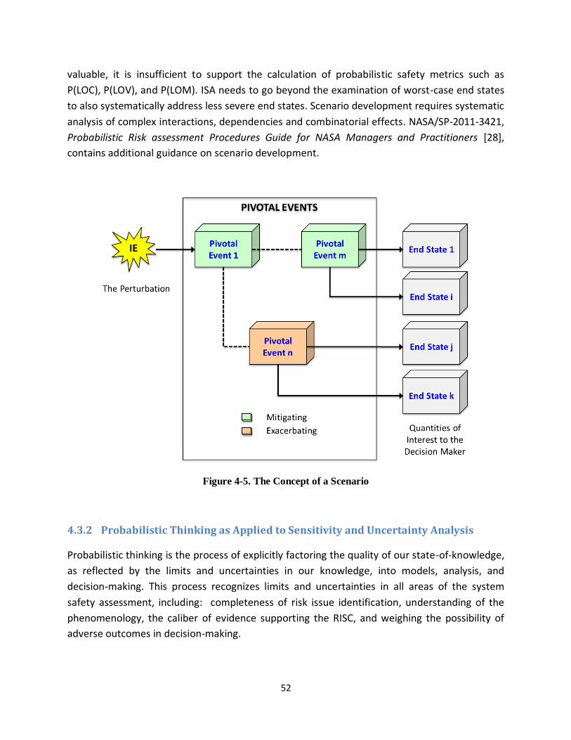
52
valuable, it is insufficient to support the calculation of probabilistic safety metrics such as
P(LOC), P(LOV), and P(LOM). ISA needs to go beyond the examination of worst-case end states
to also systematically address less severe end states. Scenario development requires systematic
analysis of complex interactions, dependencies and combinatorial effects. NASA/SP-2011-3421,
Probabilistic Risk assessment Procedures Guide for NASA Managers and Practitioners [28],
contains additional guidance on scenario development.
Figure 4-5. The Concept of a Scenario
4.3.2 Probabilistic Thinking as Applied to Sensitivity and Uncertainty Analysis
Probabilistic thinking is the process of explicitly factoring the quality of our state-of-knowledge,
as reflected by the limits and uncertainties in our knowledge, into models, analysis, and
decision-making. This process recognizes limits and uncertainties in all areas of the system
safety assessment, including: completeness of risk issue identification, understanding of the
phenomenology, the caliber of evidence supporting the RISC, and weighing the possibility of
adverse outcomes in decision-making.

53
Probabilistic thinking is important because it affects our modeling of System Safety. It forces us
to have an understanding of possible implications of both internalized information and
unwritten assumptions. Further, it is used to express internalized information via written and
verbal communications as part of the RISC.
Key elements to the probabilistic thinking process include:
Identifying and clearly describing questions and concerns that need to be described in a
probabilistic manner—i.e., clearly formulate the problem
Obtaining and evaluating relevant data and information on system performance and risk
issues
Evaluating internal assumptions and biases and describing them in a probabilistic
manner
Sensitivity and uncertainty approaches suggest where better performance would help, where
there are weaknesses and vulnerabilities in the system, the degree of margin, areas of the
Why Do We Use Probabilistic Thinking?
Probabilistic thinking is a concept pervasive to the successful implementation of the system
safety framework
The Safety Performance Measure
We cannot observe (being able to ascertain) a probabilistic safety claim, but we can evaluate
our degree of certainty (confidence) in meeting the claim probabilistically.
Application of Risk Analysis
When developing risk models (including logic-, simulation-, and phenomena-based), we
describe scenario likelihoods and consequences probabilistically.
Claims Contained in the RISC
Within a RISC a portion of the evidence and arguments justifying a safety claim is
probabilistic.
Organizational Learning
When determining the applicability of an accident precursor, we need to consider the
probability of events that must occur or conditions that need to change to result in significant
consequences.
54
“unexpected,” and where to focus resources to improve the system and reduce uncertainty.
Sensitivity analysis is a technique used to determine how different values (or data) or a
particular parameter impact a model and the effect the specific system or mission change has
on the analysis result. By performing sensitivity analysis, we build confidence in our System
Safety models by studying uncertainties that are inherently a part of data. This technique also
helps to understand the system response envelope by experimenting with a wide range of data
and assumptions: for example exploring how the system will behave during extreme
situations—i.e., not just sensitivity on data.
Uncertainty approaches rely heavily on probabilistic models and are intrinsically associated with
probabilistic thinking. Sensitivity analyses also rely on probabilistic models, but the main reason
is to establish a reasonable range for the parameters being varied.
Additional guidance on probabilistic thinking as applied to risk analysis can be found in [28].
4.3.3 Life cycle Aspects of Integrated Safety Analysis and Testing
Depending on project scale, life cycle phase, etc., different modeling rigor is appropriate in
integrated safety analysis. As a general rule of thumb, the rigor of modeling should increase
with successive program/project life cycle phases. In addition for a given phase, parametric,
engineering, and logic modeling can commence at a low level of detail; the level of detail can be
increased in an iterative fashion based on the requirement to reach a robust decision.
It is important to differentiate between model rigor and the concept of graded analysis. Model
rigor pertains to the level of detail that is included in a model and is proportional to the
maturity of the design. It would not make sense, for example, to include modeling of
components in an integrated safety analysis if the components had not yet been specified in
the design. On the other hand, graded analysis pertains more to the breadth of the modeling. In
a graded analysis, the effort devoted to analyzing a particular risk issue or scenario is
proportional to the importance of the issue or scenario being considered and whether it affects
the ability to make an informed decision. It would not be necessary, for example, to analyze all
the possible scenarios associated with an initiating event if the probability of the initiating
event were vanishingly small. Further discussion of the graded approach philosophy is provided
in Section 4.3.4.
The following approaches to modeling rigor are discussed as well in [6]. They are applicable to
different phases of the life cycle as indicated below.
55
4.3.3.1 Pre-Design Trade Studies
During pre-design trade studies, estimates can be made based on first-order simulation
methods and/or similarity estimating methods.
First-order simulation methods involve the use of closed-form or simple differential
equations that can be solved given appropriate initial and/or bounding conditions
without the need for control-volume based computational methods. The equations
may be standard physics equations of state or empirically-derived relationships from
operation of similar systems or components.
Similarity estimate methods are based on comparison and extrapolation to like items or
efforts. Reliability and operational data from one past program that is technically
representative of the program to be estimated can serve as the basis of estimate. These
data are then subjectively adjusted upward or downward, depending upon whether the
subject system is believed to be more or less complex than the analogous program.
4.3.3.2 Concept Development and Early Design
During concept development and early design, first-order simulation methods, semi-detailed
simulation estimation methods, and first-order parametric estimation methods may be
appropriate.
Semi-detailed simulation methods require the construction of a model that represents
the physical states of interest in a virtual manner using control-volume based
computational methods or methods of a similar nature. During conceptual
development, the amount of design detail in the models will be limited to what is
available and the virtual models may use computation approximations such as lumped
elements rather than finite elements.
First-order parametric estimation methods are based on historical data and
mathematical expressions that relate safety, reliability, and/or operational estimates as
the dependent variable to selected, independent, driving variables. Regression analysis
or first-order technical equations may be used.
4.3.3.3 Detailed Design
During detailed design, detailed simulation estimation methods and detailed logic modeling
estimation methods are appropriate.

56
Detailed simulation methods are an extension of the semi-detailed simulation methods
described above. These simulations typically require systems and conditions to be
modeled to a high-level of fidelity, including the use of “meshes” or network diagrams
to represent the system, its environment (either internal, external, or both), and/or
processes acting on the system or environment. Examples are computational fluid
dynamics (CFD) and finite-element modeling.
Detailed logic modeling estimation methods involve “top-down” developed but
“bottom-up” quantified scenario-based or discrete-event logic models that segregate
the system or processes to be evaluated into discrete segments. These segments are
then quantified and mathematically integrated through Boolean logic to produce the
top-level safety estimate. Detailed technical simulation and/or testing, as well as
operational data, can be used to assist in developing pdfs for quantification of the
model.
4.3.3.4 System/Component Testing and System Operation
System and component testing should be risk-informed, in that the choice of tests to be
performed and parameters to be varied should be tailored toward reducing uncertainties
pertaining to the risk drivers. The use of risk information to help with prioritization of testing
follows the same principles as its use for prioritizing program controls, commitments, and
safety related activities such as maintenance, audits, inspections, training, and certification (see
Section 4.2.4.2).
During system/component testing and system operation, various testing and operational
methodologies can be used and statistical methods can be applied.
Testing can encompass the use of table-top experiments all the way up to full-scale
prototypes operated under real-world conditions. The objective of a test is to measure
how the system or its constituent components may perform within actual mission
conditions. Testing could be used for assessing the expected performance of competing
concepts or for evaluating whether the system or components will meet flight
specifications.
Once the system is deployed, data gathered during operation can be analyzed to
provide empirically accurate representations of how the system will respond to different
conditions and how it will operate throughout its lifetime. This information can serve as
the basis for applicable changes, such as software uploads or procedural changes, that
may improve the overall performance of the system. Testing and detailed simulation

57
may be combined with operating experience to extrapolate from known operating
conditions.
Statistic methods can be applied to data collected during testing or from system
operation during an actual mission. In addition, patterns in the data may be modeled in
a way that accounts for randomness and uncertainty in the observations, and then serve
as the basis for design or procedural changes that may improve the overall safety of the
system. These methods are useful for answering yes/no questions about the data
(hypothesis testing), describing associations within the data (correlation), modeling
relationships within the data (regression), extrapolation, interpolation, or simply for
data mining activities.
Care must be taken during system/component testing to ensure that differences between the
test environment and the conditions the system will experience during operation are accounted
for in the models that are developed. For example, the effects of zero gravity must be
considered in deriving models from the data if the tests are conducted in a non-zero gravity
environment. Accounting for differences between test and operating environments may be
especially important when new technologies and/or new applications of existing technologies
are used.
4.3.4 Graded Approach Philosophy
The concept of a “graded approach” is discussed briefly in Section 4.2.1.2.1 and in more detail
in [6]. The point of a graded approach to analysis is to match analysis effort to the needs driving
the current decision process. Suppose that in the context of a key decision, an initial analysis
shows an unacceptably high upper bound of the probability of some accident scenario leading
to a high consequence, thus requiring a costly mitigation be incorporated in the design.
However, a more detailed analysis has the potential to narrow the uncertainty bounds on the
scenario’s probability of occurrence, potentially to the point where the mitigation can be
omitted (because the detailed analysis shows the probability is very low). If the more detailed
analysis is not too expensive (relative to the cost of the mitigation), then it is worth doing.
Graded Approach
A graded approach to analysis requires that the resources and depth of analysis be
commensurate with the stakes and the complexity of the decision situations being
addressed.

58
4.3.5 Use of Operating Experience and Precursor Analysis
As part of an integrated safety analysis, an update process takes place at any time during the
system life cycle when relevant new information becomes available. During the operational
phase, the information frequently involves the recognition that a precursor to an accident has
occurred. A precursor can be considered to be a transition in an accident scenario that could
lead to a full-blown accident if other events were to occur. Precursor analysis is akin to
continuous improvement based on root cause analysis, where the event that triggers the
analysis is the precursor.
Ordinarily, accidents are prevented by a combination of barriers (human and hardware or
software system features to prevent accidents). Failure of particular combinations of barriers
corresponds to an accident. A precursor is a scenario in which some barriers are at least
partially degraded. Attributes of precursors include:
Observation indicates some failure mechanism
Same mechanism could occur again
The consequences could be more severe than what has been experienced
While a precursor is an indication of a problem that could recur with more severe
consequences, it is also an opportunity to learn. Precursor analysis is unique in that it explicitly
assesses risk implications of occurring events. Events that are analyzed include not only failures,
but also the more general class of anomalies and issues. To assess risk implications of an event,
two general questions are asked:
1. What events were needed to occur or what conditions were needed to change to result
in significant consequences?
2. What is the likelihood of these additional events or conditions that were needed?
Since precursors are “pre-accidents,” they could represent a variety of events such as a near-
miss because of an opportune mitigation; faults that can become failure conditions without
correction; unexpected trends in test, operation, or maintenance; or common causes of faults
or deteriorations.
An active and effective precursor analysis program can lead to changes in the design or
operating practice before an accident ever occurs. Learning will often require relinquishing or
admitting to a previous misunderstanding or analysis error, or revising the assessment of
uncertainty in a particular area of modeling.

59
Ultimately, organizational learning through precursor analysis helps to couple operational data
and practices (the reality) to the models used for System Safety (the prediction of reality) as
shown in Figure 4-6.
Additional guidance on precursor analysis can be found in [13].
Figure 4-6. Example of how Learning Informs Decisions and Models in the Mission Life Cycle
4.4 Special Topics Pertaining to Risk-Informed Allocations of Safety
Thresholds and Goals
Safety performance measures such as P(LOC) or P(LOV) are integral metrics and are very closely
related to fundamental safety objectives of a program/project at the highest level. Depending
upon the characteristics of the mission, P(LOC) is generally the metric of principal interest for

60
crewed missions, P(LOV) for robotic missions with recoverable and reusable elements, and
P(LOM) for robotic missions with all elements expendable.
In order to facilitate the achievement of the high level probabilistic requirements without
requiring multiple design iterations, it is common practice for probabilistic allocations to be
made from the top level down to the lower elements of the system. In this way, the ownership
of the safety requirements similarly is allocated from program/project level down to the lower
organizational units supporting the program/project.
For illustration purposes, it is convenient to discuss allocation as occurring in three tiers,
although in practice, the tiers may often be conducted in unison. The first tier involves
allocating reliabilities to lower level operational elements in the system. Such elements would
include normally operating hardware components, the associated software that controls the
operation of the hardware, and the human operators in the launch and mission control centers
who send commands from Earth to the spacecraft. Because the top requirements are
expressed in failure space (e.g., loss of vehicle rather than survival of the vehicle), the lower
level requirements are also expressed in failure space (i.e., failure probabilities on demand,
mean failure rates, or unreliabilities rather than success probabilities, mean success rates, or
reliabilities).
The second tier in the allocation process expands upon the items mentioned above to include
consideration of the logic for recovery from faults, along with the associated probabilities that
the fault is detected, that it is within the coverage of the fault management system, and that
the actions to recover from the fault are successful. Coverage probabilities refer to the
probability that each fault that is encountered is one from which the system can recover
through the actions of control personnel on the ground and/or on-board control logic. Because
we are still dealing with failure space in the definition of the top-level safety performance
measures, the allocations pertain to the probabilities of lack of detection, lack of coverage, and
lack of successful execution.
The third tier of the allocation process is really a special subset of the second tier (fault
management) that applies specifically to crewed missions. It further expands upon the
elements listed above to include the control logic for crew abort and the corresponding
effectiveness of abort actions. Abort effectiveness depends upon the range of environments
that the abort system may experience during an abort, as well as the relative likelihoods of
encountering each environment. In turn, the nature of the environments that the abort vehicle
will encounter depends upon the particular system failure that necessitates the abort and the
amount of time it takes to initiate the abort. In failure space, the allocation concerns the
probabilities that abort will be unsuccessful for each environment that may be encountered.

61
Once failure probabilities or failure rates have been allocated, the designers, with the help of
reliability experts, have to determine a design approach that meets those allocations. Designers
have several means for increasing the reliability of a system:
They can add redundancy, such that multiple failures are required before a critical
function is lost. Redundancy can be applied not only for hardware elements but also for
software elements and for tasks performed by humans. The failure probability/rate of
the redundant system can be determined mathematically from the failure
probabilities/rates of the components within it (e.g., [29,30]). If there are similar
components that are subject to failure from a common source or mechanism, the
mathematical formulation must account for these common-cause failure possibilities.
They can replace less reliable components with more reliable components. There are
many sources of information to assist the designer in making replacements to improve
reliabilities for all three elements (hardware, software, and human). These include the
use of hardware and software reliability data from vendors to assist in the selection of
the replacement component, use of ground test and operational flight data, and use of
handbooks that provide reliability shaping factors as a function of environmental
stressors (e.g., [31-33]) .
They can add design margin for hardware components whose failure probabilities/rates
are sensitive to physical stressors such as temperature, mechanical loads, and radiation
levels. The relationship between design margin and failure probabilities/rates can be
estimated from phenomenological models (e.g., [34]).
Of course, the implications of adding reliability on other system requirements, such as vehicle
mass, schedule, and cost, have to be taken into consideration through the risk management
processes described in Section 4.2.
The following subsections describe the development and application of logic models to allocate
safety thresholds and goals for each of the three tiers of allocation mentioned above.
4.4.1 Use of Risk Logic Modeling to Allocate Failure Probabilities/ Rates for
Normally Operating Components of the System
The process of risk informing the allocation of failure probabilities/rates to lower levels starts
from developing logic models (such as fault trees or reliability block diagrams) and continues
with applying them in a quantitative fashion. As illustrated in Figure 4-7, the “top event” for a
logic model used in a safety analysis may be LOC, LOV, or LOM, the midlevel events represent
failures of subsystems, and the lowest level events are failures of the hardware, software, and
human components of the system or failures at their interfaces. The combinations of failure
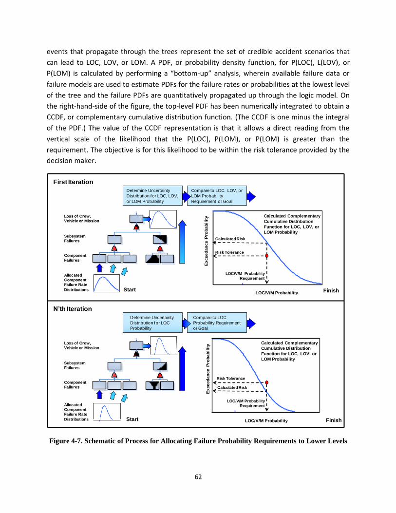
62
events that propagate through the trees represent the set of credible accident scenarios that
can lead to LOC, LOV, or LOM. A PDF, or probability density function, for P(LOC), L(LOV), or
P(LOM) is calculated by performing a “bottom-up” analysis, wherein available failure data or
failure models are used to estimate PDFs for the failure rates or probabilities at the lowest level
of the tree and the failure PDFs are quantitatively propagated up through the logic model. On
the right-hand-side of the figure, the top-level PDF has been numerically integrated to obtain a
CCDF, or complementary cumulative distribution function. (The CCDF is one minus the integral
of the PDF.) The value of the CCDF representation is that it allows a direct reading from the
vertical scale of the likelihood that the P(LOC), P(LOM), or P(LOM) is greater than the
requirement. The objective is for this likelihood to be within the risk tolerance provided by the
decision maker.
Figure 4-7. Schematic of Process for Allocating Failure Probability Requirements to Lower Levels
Determine Uncertainty
Distribution for LOC, LOV,
or LOM Probability
Compare to LOC. LOV, or
LOM Probability
Requirement or GoalE
xceed
an
ce
Pro
bab
ilit
y
LOC/V/M Probability
Risk Tolerance
Calculated Complementary
Cumulative Distribution
Function for LOC, LOV, or
LOM Probability
Calculated Risk
LOC/V/M Probability Requirement
Subsystem Failures
Component Failures
Loss of Crew, Vehicle or Mission
Allocated Component Failure Rate
Distributions
Determine Uncertainty
Distribution for LOC
Probability
Compare to LOC
Probability Requirement
or Goal
Exceed
an
ce
Pro
bab
ilit
y
LOC/V/M Probability
Risk Tolerance
Calculated Complementary
Cumulative Distribution
Function for LOC, LOV, or
LOM Probability
Calculated Risk
LOC/V/M Probability Requirement
Subsystem Failures
Component Failures
Loss of Crew, Vehicle or Mission
Allocated Component Failure Rate
Distributions
N’th Iteration
First Iteration
Start Finish
Start Finish

63
The need to allocate lower level failure probabilities that are different from those obtained
from failure data and models occurs when the calculation indicates that the LOC, LOV, or LOM
probability requirement cannot be met within the decision maker’s risk tolerance. In that case,
the reliabilities of the components must be increased beyond their usual or typical values. As
shown in Figure 4-7, several iterations may be necessary before settling upon a set of allocated
component reliabilities that achieves the overall safety requirement and is practicable.
There are several methods in the literature that are used for determining how much to increase
the reliability of each component (hardware, software, or human) and the reliabilities of their
interfaces. One method is based on developing cost functions that relate how much it would
cost to increase the reliability of each component by a given amount [35]. When this
information is propagated through the logic model, the result is a map of how increases in the
reliability of each component affect both the probability of LOC, LOV, or LOM and the cost to
the program/project. This method has the potential for achieving the desired probability of LOC
LOV, or LOM at minimum cost.
Many times, the minimum cost solution may have to be modified to take account of other
factors that come into play (e.g., availability of parts, fabrication questions, operation aspects,
maintenance, and sustainability). For this reason, the allocation process is deliberative,
involving a collaborative interaction between the designers and the safety analysts.
4.4.2 Special Considerations to Account for Fault Management Capabilities
The allocation process discussed in the preceding subsection can be extended to include fault
management capabilities. Often this extension can be accomplished simply by adding recovery
paths in the logic model (e.g. fault tree) that has already been developed to allocate failure
probabilities/rates for normally operating components (e.g., Figure 4-8). These recovery paths
include events that pertain to whether the fault is detected, whether it is covered by the fault
management logic, and whether the recovery system operates successfully. In the simplest
cases, probability distributions for these events are generated offline and are treated as inputs
to the logic model.
If the recovery process is complex and is dependent upon the timing and ordering of actions
taken, however, it may be necessary to develop more complex logic models. These could
include Markov chains and/or dynamic fault trees [36] in place of the simpler construct shown
in Figure 4-8. These time-dependent logic models are typically solved in a time-marching
fashion and may require the use of a Monte-Carlo sampling process. More information on this
subject will be provided in Volume 2.

64
Figure 4-8. Schematic Modification of Process for Allocating Failure Probability Requirements to
Lower Levels to Include Fault Management Provisions
4.4.3 Special Considerations for Crewed Systems with Abort Capability
As stated previously, NASA has established a set of agency-level safety goals and thresholds for
crewed missions to the ISS that, given the reliabilities of the current generation of state-of-the-
art launch vehicles, will require robust launch abort capability in order to protect the crew in
the face of mission-ending launch vehicle failure. The allocation process for P(LOC) therefore
naturally decomposes into reliability constraints on the launch vehicle and abort effectiveness
constraints on the aborting crew vehicle.19 However, abort effectiveness is highly dependent on
launch vehicle failure mode, specifically:
The ability to detect the launch vehicle failure in a timely manner
19 The reliability of the crew vehicle during nominal mission operations also factors in to the vehicle-level safety performance, but is not directly relevant to a discussion of abort.
Determine Uncertainty
Distribution for LOC, LOV,
or LOM Probability
Compare to LOC. LOV, or
LOM Probability
Requirement or Goal
Exceed
an
ce
Pro
bab
ilit
y
LOC/V/M Probability
Risk Tolerance
Calculated Complementary
Cumulative Distribution
Function for LOC, LOV, or
LOM Probability
Calculated Risk
LOC/V/M Probability
Requirement
Subsystem
Failures
Non-recovered
Component
Failures
Loss of Crew,
Vehicle or Mission
Recovery
Models
Iteration
Non-
coverage
Non-
detection
Recovery
Component
Failure
Allocated
Conditional
Input
Distributions
Flight
Component
Failure
Failed Not
Recovered
and
Failed Not
Recovered
and
A B A B
A B
Start
Finish
WaitRetry Return to
Checkpoint Recover
FailureRestoration
Isolation

65
The abort conditions created by the failing launch vehicle while the aborting vehicle is
mated to it, and as it is leaving the launch vehicle vicinity
The time into flight at which launch vehicle failure occurs
Therefore, it is not necessarily constructive to allocate a single reliability to the launch vehicle,
irrespective of failure mode; nor is it necessarily meaningful to allocate a single abort
effectiveness to the abort vehicle, irrespective of the environments from which it must abort.
Instead, the contribution to P(LOC) from each launch vehicle failure mode should be separately
evaluated in terms of the probability of occurrence of the failure mode and the effectiveness of
the abort system against it. Within the logic model, the contribution to P(LOC) from abort is the
disjunction of the contributions to P(LOC) from each of the individually-analyzed launch vehicle
failure modes, as shown in Figure 4-9.
Figure 4-9. Schematic Modification of Process for Allocating Failure Probability Requirements to
Lower Levels to Include Launch Abort Capability
Abort is a complex and dynamic operation. Consequently, abort modeling typically involves
modeling of the physical phenomena associated with the aerodynamic loads on the abort
Determine Uncertainty
Distribution for LOC
Probability
Compare to LOC
Probability Requirement
or GoalE
xce
ed
an
ce
Pro
ba
bil
ity
LOC Probability
Risk Tolerance
Calculated Complementary
Cumulative Distribution
Function for LOC
Probability
Calculated Risk
LOC Probability
Requirement
Loss of Crew due
to Launch Vehicle
Failure
Loss of Crew due
to Launch Vehicle
Failure Mode
Loss of Crew
Start
Finish
Detect
Separate
Stabilize
Land
Recover Crew
Abort
Effectiveness
Models
Iteration
Abort
Failure
Allocated
Conditional
Input
Distributions
Launch
Vehicle
Failure
Failure
Mode 1
Occurs
Abort
Fails
and and
A B A B
A B
Failure
Mode n
Occurs
Abort
Fails

66
vehicle, the overpressures and debris fields produced by the launch vehicle should it explode,
the ability of crew vehicle to withstand the abort environment, etc. A Monte-Carlo sampling
process is typically used to quantify abort effectiveness, either as a function of mission time or
integrated over the ascent.
An additional issue with respect to crewed systems with abort capability is the fact that abort
systems are only demanded during crew-threatening launch vehicle failures, and therefore do
not generate a flight history that can be used to significantly reduce epistemic uncertainties and
gain confidence in system performance. This situation increases reliance on analysis,
particularly in the form of simulation, as well as testing, to demonstrate compliance with
allocated abort effectiveness probabilities. More information on crewed systems with abort
capability will be provided in Volume 2.
4.5 Collaborative Development of Controls
Controls are developed through collaboration between the system safety and design
disciplines. Development of controls in a complicated system is difficult and there are many
considerations to be addressed:
Budget, mass, and other performance measures.
The need not to introduce new hazards in the course of changing the system to mitigate
a given hazard. (For example, adding a sensor to more quickly/accurately detect a
failure condition may introduce a new weakness stemming from having to make yet
another penetration in a pressure vessel.)
The need to consider the controls as a portfolio. A given control may address multiple
hazards, and may be net-beneficial considering all of the hazards mitigated, even though
it would be too expensive in money or mass to be justified for any one hazard.
Conversely, a control that is very effective at reducing a single hazard may be found to
be superfluous in the context of the entire set of controls. This is an illustration of the
benefits of “holistic thinking” this guidebook strives to encourage. Further elaboration
on this point will be provided in Section 4.5.1.
The need to consider the interactions among controls. One control may counteract
another control. For example, two controls may each reduce the risk substantially if
applied individually, but if applied jointly might only reduce risk by an insignificant
amount. Alternatively, they may collectively result in a slight reduction of the probability
of LOC but a substantial increase in the probability of injury, or loss of assets.

67
Some risks may be controllable up to a point without resorting to design modifications, through
changes to operating practice or mission profile. A prominent example is measures taken in
space shuttle operation to avoid damage from micrometeoroids and orbital debris (MMOD).
In general, since scenarios and risks frequently involve interfaces between different parts of a
system, a holistic, integrated analysis on complex systems can only be done correctly in a
collaborative environment. Figure 4-10 illustrates conceptually how causal factors, controls,
and models may be correlated.
Figure 4-10. Development of Controls must be Performed in a Collaborative Environment due to
the Interactions of Causal Factors, Controls, and Models
4.5.1 Cause-Specific versus Generic Controls
It is convenient to think of controls in terms of two types: cause specific and generic. A cause
specific control is one that acts on only one specific underlying controllable cause, whereas a
generic control is one that acts on many. For example, replacement of a specific unreliable
component with a different component is a cause-specific control, whereas controls to increase
overall due diligence with respect to quality assurance are generic controls. Within the category
of generic, one can also speak in terms of controls that apply to the whole project or to
different phases of the project.
Objective
Controls
Causes
Models
Safe System
Causal Factors for Failure
ROCKET
Rocket Fails
1.0000E+00FAILURE_1
Failure Mode 1
ROCKET1
1.0000E+00FAILURE_2
Failure Type 2
1.0000E+00FAILURE_3
Failure Type 3
1 2 3 n…
Mitigation 1 Mitigation 2 Mitigation i

68
Examples of controls that are generic for all mission phases include:
Provisions to ensure that all safety-related issues raised at any level of the organization
are aired and resolved
Provisions to ensure independence and authority of the safety organization to address
all safety-related issues
Provisions to ensure that adequate procedures are in place for all safety-related
activities
Provisions to ensure that employees and contractors are adequately and frequently
trained in procedures that relate to safety
Examples of controls that are design generic include:
Controls to ensure functional redundancy in the design wherever possible
Controls to ensure single points of failure and common cause failures are adequately
addressed
Examples of controls that are testing generic include:
Controls to ensure that all critical components are tested as-flown
Controls to ensure that all testing activities that have potential safety implications are
adequately monitored
Examples of controls that are flight operations generic include:
Controls to ensure that emergency procedures are carried out correctly
Controls to ensure that ad-hoc procedures are monitored by ground personnel
Controls that are cause-specific focus attention on risks that are known. They have the
potential to prevent or mitigate particular risks at less cost and with less overall impact to the
program/project at large than generic controls. However, generic controls have the potential
for controlling a broader swath of risks at lower overall cost than a collection of cause-specific
controls. Generic controls increase the potential for reducing the cumulative impact of risks
that are unknown. Their greatest potential is realized when the generic controls, taken as a
whole, cover all phases within the program/project, all activities within each phase, and all
organizational units contributing to the program/project.
A strong set of controls will include both cause-specific and generic controls.

69
5 The Risk-Informed Safety Case (RISC)
5.1 Introduction
System safety has existed for many years. However, system safety practice is continuing to
evolve. A key concept that has proven its value in other application areas is the concept of the
“safety case.” This chapter discusses the elements for producing a risk-informed safety case,
presents an example of the structure of a RISC, and provides further examples of how the
decision maker might choose to use the RISC to evaluate whether the system is adequately
safe.
Historically, safety cases have a heritage tracing back to the 1960’s in the United Kingdom, and
have been widely adopted in high-profile safety critical industries in Europe and Australia,
including nuclear installations, industrial plants, defense procurement and transportation. The
safety case concept has also been extended to apply to additional system attributes beyond
just safety, resulting in “Assurance Cases” and “Dependability Cases”.
For purposes of NASA system safety practice, the term ‘risk-informed safety case’ (RISC) is used,
to emphasize that a determination of adequate safety is the result of a deliberative decision
making process that necessarily entails an assessment of risks and tries to achieve a balance
between the system’s safety performance and its performance in other areas.
The risk-informed safety case (RISC) is the means by which an organization manifestly takes
ownership of a system’s safety and which makes the case to decision makers, at major
milestones such as Key Decision Points (KDPs), that the system’s safety objectives have been
achieved. It is a structured argument, supported by a body of evidence, that provides a
compelling, comprehensible and valid case that a system is or will be adequately safe for a
given application in a given environment.20
The validity of the RISC is conditional on a specified application of the system within a specified
environment; hence the RISC must clearly define the operational envelope within which the
system is claimed to be safe. If this envelope is penetrated, then one or more claims may no
longer be valid and the system may no longer be adequately safe.
The RISC is specific to the decision context (e.g., milestone review) for which it is constructed.
Therefore, a system may have a number of RISCs over the course of its development and
operational life, corresponding to the various points in its life cycle where it is necessary to
show that the safety objectives have been, or will be, met. Of course, it is to be expected that
the RISC developed for a particular decision context will make maximum use of any RISCs for
20 Adapted from [15].

70
that system that were developed for prior decision contexts, updated with new analysis, data,
plans, etc., as needed to show that the safety objectives of the current context have been met.
As such, the RISC can be viewed as a single product that evolves, and is periodically rebaselined,
over the system life cycle, as opposed to a set of individual products developed for a sequence
of milestones. The distinction is purely semantic, and this handbook adopts the convention that
a separate RISC is developed for each decision context requiring one.
Developing a RISC involves [17]:
Making an explicit set of claims about the system(s), for example, the probability of an
accident or a group of accidents is low compared to some standard or constraint
Producing evidence that supports the claims, for example, representative operating
history, redundancy in design, or results of analysis
Providing a set of safety arguments that link the claims to the evidence
Making clear the assumptions and judgments underlying the arguments
The claims made (and defended) by the RISC are the safety objectives negotiated at the outset
of system formulation. In other words, each distinct safety objective is stated as a
corresponding distinct claim in the RISC. By successfully substantiating each claim, the RISC
shows that the corresponding objective has been met and, thus, that the system is adequately
safe.
Each organizational unit that participates in a program/ project can be considered to have its
own objectives that derive, basically, from the allocation of safety requirements from higher
levels. (The allocation of safety performance requirements has been discussed in Sections 2.3.2,
3.2.2, 4.2.1.6, and 4.4.) Thus, each organizational unit can produce its own RISC purporting to
show that its objectives have been satisfied with sufficient confidence. The overall RISC for the
system incorporates the RISCs from each organizational unit.
The RISC does not need to include exhaustive details – it may refer to supporting evidence tied
to key claims contained in other documents. Furthermore, the RISC is not an analysis, although
it typically contains results of analyses. It is not, for example, an ISA, although it may include an
ISA. Rather, it is the marshaling of available evidence into an argument to support a decision
regarding the adequacy of safety of a system.
71
5.2 Elements of the RISC21
The main elements of the RISC are:
A set of safety claims about the safety of the system. Taken together, the safety claims
should substantiate the overarching claim that the operational safety objectives defined
for the system have been met (ipso facto that the system is adequately safe). The most
straightforward way to structure the claims is for each operational safety objective to be
rephrased as a claim that the objective has been met.
Evidence that is used as the basis of the safety argument. This can be either facts (e.g.,
established scientific principles or empirical data), explicit assumptions, or sub-claims.
Structured safety arguments that link the evidence to the safety claims, and which use
logically valid rules of inference. Safety arguments can be deterministic, probabilistic, or
qualitative.
The use of these elements is illustrated in Figure 5-1 and Figure 5-2. These figures show a step
in the argument in which a claim is subdivided into a mix of evidence and sub-claims, which
illustrates the hierarchical structure of the RISC. Each sub-claim is a claim in its own right, which
the RISC elaborates with further steps in the argument. This makes it easier to understand the
overall argument and to partition the RISC activities. In particular, RISCs produced by
subordinate organizational units (e.g., sub-system-level units) can be used as sub-claims of the
RISC at the next higher level of the NASA hierarchy. This allows demonstration of sub-claims to
propagate upward, as RISCs are evaluated and accepted at successively higher levels of the
organizational hierarchy. Conversely, it means that the RISC at a given level can at best be
considered provisional until all subordinate RISCs have been accepted. The approach can be
applied recursively, so that substantiated claims about a subsystem can be used as evidence in
a parent case [37].
Figure 5-2 illustrates a situation where two independent arguments support the same safety
claim. The first argument is supported by a single piece of evidence, whereas the second
argument is supported by the combination of a different piece of evidence along with a pre-
existing sub-claim. Both arguments support the claim without depending on the other
argument. By using independent evidence and arguments, the claim is made more robust, i.e.,
it can tolerate flaws in a single argument.
21 Adapted from [17].

72
Figure 5-1. Use of RISC Elements to Support a Safety Claim22
Figure 5-2. A Safety Claim Supported by Two Independent Arguments23
5.2.1 Sources of Evidence
The arguments are supported by evidence from the following main sources:
The design
The development processes, including processes for system realization and operation
Test results
Validated models and simulations
22 Adapted from [17]. 23 Ibid.
Claim
Evidence EvidenceSub-claim
Argument Structure
Claim
Evidence EvidenceSub-claim
Argument Structure

73
System operational data
Historical data
Documented management and quality assurance plans
Documented procedures including verification and validation procedures
Documented training material
Other documented program/project controls
5.2.2 Types of Safety Argument
Different types of safety arguments can be used to support safety claims:
Deterministic arguments: The application of predetermined rules to derive a true/false
claim, given some initial assumptions (e.g., demonstration of compliance to a
specification or safety requirement, assertion of known physical attributes such as
physical laws and material properties, etc.).
Probabilistic arguments: Quantitative statistical reasoning that establishes a
probabilistic claim. For example, to substantiate a claim that the probability of loss of
mission P(LOM) for some system is X, a probabilistic argument would reason statistically
from evidence to quantify P(LOM).
Qualitative arguments: Compliance with rules that have an indirect link to the desired
attributes (e.g. compliance with industry standards, crediting of staff skill and
experience, etc.).
The choice of argument will depend on the available evidence and the type of claim. For
example, claims for reliability would normally be supported by statistical arguments, while
other claims (e.g. for maintainability) might rely on more qualitative arguments such as
adherence to codes of practice.
Additionally, safety arguments can be classified in terms of their role in supporting a safety
claim:
A direct or demonstrative argument uses evidence to show that a particular objective
has been achieved. A direct argument has the general structure, “Given the evidence,
the objective has been met.”

74
An indirect, backing, or validating argument shows that the evidence used in a direct
argument is trustworthy. The evidence brought to bear in a backing argument typically
addresses issues such as the quality or applicability of data and the capabilities of
practitioners. A backing argument has the general structure, “Given the (backing
argument’s) evidence, the direct argument’s evidence can be relied on.”
5.3 RISC Life Cycle Considerations
As discussed in Section 2.1, the concept of adequate safety requires that safety is addressed
throughout all phases of the system life cycle. This translates into the development of safety
objectives that span the full life of the system, from concept studies to closeout.
Correspondingly, the RISC must also address the full system life cycle, regardless of the
particular point in the life cycle at which the RISC is developed. This manifests in the RISC as two
distinct types of safety claims:
Claims related to the safety objectives of the current or previous phases argue that the
objectives have been met.
Claims related to the safety objectives of future phases argue that a ‘roadmap’ has been
established for the satisfaction of objectives yet to be met, i.e., that necessary planning
and preparation have been conducted and that commitments are in place to meet the
objectives at the appropriate time.
The form of the RISC arguments for accomplished objectives vs. upcoming objectives is shown
in Figure 5-3 for the point in time at which design has completed and realization is about to
commence. As the system proceeds in the life cycle and RISCs are developed for successive
milestones, arguments demonstrating an ability and commitment to meeting objectives are
replaced by arguments demonstrating accomplishment of objectives.
5.3.1 Transitioning from Safety Thresholds to Safety Goals
In the case of a system for which the initial minimum tolerable level of safety is defined by a
safety threshold, but which is expected to undergo safety growth during operation and
ultimately meet a stricter safety goal, the RISC must make a case that a program of continuous
improvement is planned or in place that has a reasonable expectation of producing the
requisite safety improvement. In other words, the RISC must provide a roadmap towards the
satisfaction of the safety goal in terms of the plans, and commitments necessary for making
that level of safety come true. The form of argument for safety improvement is likely to be
probabilistic and/or qualitative, since such improvements typically depend on activities, such as
testing, whose outcomes cannot be predicted with certainty beforehand.

75
Figure 5-3. Coverage of the System Life Cycle in the RISC
5.3.2 Maintaining a High Level of Safety throughout the Mission Life
In cases where life limiting factors and reliability degradation due to wear-out are areas of
concern (e.g., for robotic missions of long duration), it is necessary to show as part of the RISC
that the reliability of the system will remain adequately high throughout its design life.
5.4 An Example RISC Structure
The high-level structure of the RISC is determined by the safety objectives negotiated at the
outset of system formulation. The most straightforward relationship between the safety
objectives and the RISC is for each claim in the RISC to correspond to an operational safety
objective of the task. This situation is shown in Figure 5-4, which restates the objectives of
Figure 3-5 as claims about the safety of the system. Because the operational safety objectives
have been derived from the top-level objective, “The system is adequately safe,” the burden of
the RISC is to substantiate them, in which case the top-level objective is also substantiated.
The figures in this section are intended to illustrate the overall structure that a particular safety
case might have. They are not meant to prescribe a general safety case structure, nor are they
meant to suggest a limit to the depth or complexity of an actual safety case. Volume 2 will
provide specific safety case examples and present formats such as Goal Structuring Notation
(GSN) for structuring claims [38].
Preliminary
DesignOperation
Life Cycle
Design
Safety ObjectivesRealization
Safety Objectives
Operation
Safety Objectives
RISC: Argues that the design
safety objectives have been
met
Argues that there is an ability and commitment to meeting
the realization and operation safety objectives
Current milestone
for which the RISC
is being developed
System safety processes
usedSystem safety processes planned

76
Figure 5-4. Top-Level Claims of the Example RISC
5.4.1 RISC Design Claims
Figure 5-5 shows that part of Figure 5-4 pertaining to system design, including the four
operational design safety claims at the leaves of the tree. These are the design claims that the
RISC must substantiate.
The system is
adequately safe
The system meets or
exceeds the minimum
tolerable level of safety
The system is as safe
as reasonably
practicable (ASARP)
The as-built system
meets or exceeds the
minimum tolerable level
of safety
The as-operated
system meets or
exceeds the minimum
tolerable level of safety
The system design is
as safe as reasonably
practicable
The as-built system is
as safe as reasonably
practicable
The as-operated
system is as safe as
reasonably practicable
Appropriate historically-
informed defenses
against unknown and
un-quantified safety
hazards are
incorporated into the
design
System realization is
responsive to new
information
System operation
decisions are risk
informed
Allocated requirements
are consistent with
achievable safety
performance
System operation is
responsive to new
information
The introduction of
potentially adverse
conditions during
system realization is
minimized
The system design
meets or exceeds the
minimum tolerable level
of safety
Design solution
decisions are risk
informed
Levied requirements
that affect safety are
complied with during
system realization
Levied requirements
that affect safety are
complied with during
system operation
System realization
decisions are risk
informed
The introduction of
potentially adverse
conditions during
system operation is
minimized

77
Figure 5-5. RISC Design Claims Derived from Design Objectives
RISC Design Claim, “The system design meets or exceeds the minimum tolerable level
of safety.”
Figure 5-6 shows an example RISC structure for the claim, “The system design meets or
exceeds the minimum tolerable level of safety.”
At the first level of decomposition, this claim makes the two sub-claims:
o The results of the ISA show that the system design exceeds the tolerable level of
safety. This is a direct argument for the higher-level claim.
o The ISA has been properly conducted. This is a backing claim for the first sub-
claim. It argues that the evidence supporting the first sub-claim, namely the ISA,
is trustworthy.
The system
design is
adequately safe
The system design
meets or exceeds
the minimum
tolerable level of
safety
The system design is
as safe as
reasonably
practicable (ASARP)
Design solution decisions are risk
informed
Allocated
requirements are
consistent with
achievable safety
performance
Appropriate historically-informed
defenses against unknown and un-quantified safety
hazards are incorporated into
the design

78
Figure 5-6. RISC Design Claim, “The System design meets or exceeds the minimum
tolerable level of safety.”
The claim that the ISA has been properly conducted is further decomposed into the
claims that the design solution is sufficiently well developed to support the ISA; that the
analysts are qualified to conduct the ISA; that the ISA methods used are appropriate to
the level of design solution definition and the decision context; and that unknown and
un-quantified safety hazards do not significantly impact safety performance. These are
the attributes of the ISA that the sub-claim argues are necessary and sufficient to find
The system design meets or
exceeds the minimum tolerable
level of safety
The ISA shows that the
design solution meets the
allocated safety goal/
threshold requirements.
An ISA has been properly
conducted
The ISA analysts are fully
qualified to conduct the
ISA
The ISA methods used are
appropriate to the level of
design solution definition
and the decision context
The design solution has
been sufficiently well
developed to support the
ISA
ISA methods:
Identify hazards
comprehensively
Characterize initiating
events and system
control responses
probabilistically
Quantify events
consistent with
physics and available
data
...
Design solution elements::
ConOps
DRMs
Operating
environments
System schematics
Design drawings
...
Unknown and un-
quantified safety hazards
do not significantly impact
safety performance
Adjusted/waived
requirements, standards,
best practices do not
significantly increase
vulnerabilities to unknown/
unquantified hazards
The design is robust
against identified but un-
quantified hazards
The design minimizes the
potential for vulnerability to
unknown hazards
The design incorporates:
Historically-informed
margins against
comparable stresses
Appropriate
redundancies
Appropriate materials
for intended use
Appropriate
inspection and
maintenance
accesses
...
The design incorporates:
Minimal complexity
Appropriate TRL
items
Proven solutions to
the extent possible
Appropriate
inspection and
maintenance
accesses
...

79
the ISA trustworthy to use in the manner that it is being used, i.e., for comparison
against the minimum tolerable level of safety.
The depth of argument and extent of evidence needed to support the claims ultimately
depends on decision maker needs, and expectations are negotiated up front in the form
of evaluation protocols. The terminal boxes containing bulleted items notionally indicate
the expectation that:
o Each of the major design solution elements would be documented, and an
argument would be made that this level of definition is adequate for the decision
context to which the RISC is applied.
o The ISA methods suit the level of design definition and adequately accomplish
the necessary system safety function of identifying and characterizing potential
accident scenarios in terms of accident causes, contributing factors,
effectiveness of controls, the probabilities of the potential end states, etc.
o The design is suitably robust against un-quantified hazards by virtue of
appropriate margins, redundancies, materials, accesses, etc.
o The design minimizes the potential for vulnerability to unknown hazards by
virtue of simplicity, technological maturity, the use of proven solutions,
appropriate accesses, etc.
RISC Design Claim, “Design solution decisions are risk informed.”
Figure 5-7 shows an example RISC structure for the claim, “Design solution decisions are
risk informed.”
At the first level of decomposition, this claim makes the two sub-claims:
o RIDM has been conducted to select a design that is ASARP.
o Requirements have been tailored, and standards and best practices have been
adopted, which supports the selected design.
These are direct claims, both of which are necessary for substantiating the higher level
claim. The first claim is supported by argument and evidence related to the proper
conduct of RIDM, i.e., that stakeholder objectives have been properly understood and
that requirements have been allocated from the next higher organizational unit. The
second claim is supported by argument and evidence related to the acceptable tailoring
of requirements, standards, and best practices, i.e., that a comprehensive initial set has
been identified, and that there is an appropriate analytical basis for each

80
adjustment/waiver from that initial set that demonstrates adherence to the ASARP
principle.
Figure 5-7. RISC Design Claim, “Design solution decisions are risk informed.”
RISC Design Claim, “Allocated requirements are consistent with achievable safety
performance.”
Figure 5-8 shows an example RISC structure for the claim, “Minimum tolerable levels of
safety have been allocated consistent with achievable safety performance.”
Design solution decisions
are
risk informed
RIDM has been conducted
to select the design that
maximizes safety without
excessive performance
penalties in other mission
execution domains
The tailored set of
requirements, standards,
and best practices to
which the design complies
supports a design solution
that is as safe as
reasonably practicable
The RIDM analysts are
fully qualified to conduct
RIDM
The RIDM methods used
are appropriate to the life
cycle phase and the
decision context
Stakeholder objectives are
understood and
requirements (or imposed
constraints) have been
allocated from the level
above
RIDM methods:
Identify alternatives
Analyze the risks
associated with each
alternative
Support the risk-
informed, deliberative
selection of a design
alternative
The set of applicable
requirements, standards,
and best practices was
comprehensively identified
There is an appropriate
analytical basis for all
adjustments/waivers to
requirements, standards,
and best practices
Adjusted/waived
requirements, standards,
best practices:
Improve the balance
between analyzed
performance
measures
Preserve safety
performance as a
priority
Do not significantly
increase
vulnerabilities to
unknown/
unquantified hazards
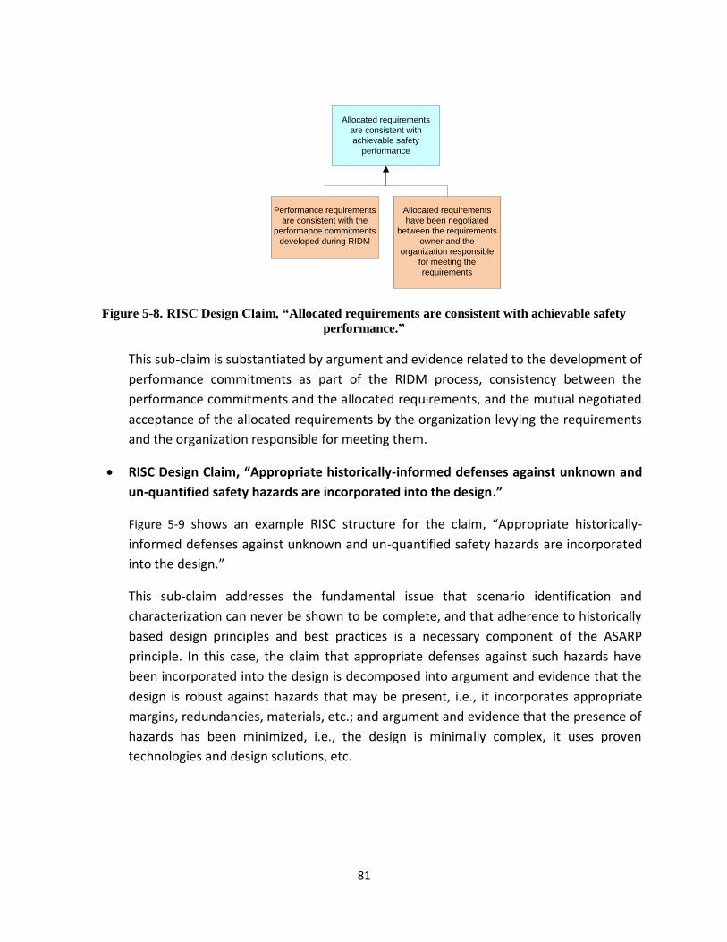
81
Figure 5-8. RISC Design Claim, “Allocated requirements are consistent with achievable safety
performance.”
This sub-claim is substantiated by argument and evidence related to the development of
performance commitments as part of the RIDM process, consistency between the
performance commitments and the allocated requirements, and the mutual negotiated
acceptance of the allocated requirements by the organization levying the requirements
and the organization responsible for meeting them.
RISC Design Claim, “Appropriate historically-informed defenses against unknown and
un-quantified safety hazards are incorporated into the design.”
Figure 5-9 shows an example RISC structure for the claim, “Appropriate historically-
informed defenses against unknown and un-quantified safety hazards are incorporated
into the design.”
This sub-claim addresses the fundamental issue that scenario identification and
characterization can never be shown to be complete, and that adherence to historically
based design principles and best practices is a necessary component of the ASARP
principle. In this case, the claim that appropriate defenses against such hazards have
been incorporated into the design is decomposed into argument and evidence that the
design is robust against hazards that may be present, i.e., it incorporates appropriate
margins, redundancies, materials, etc.; and argument and evidence that the presence of
hazards has been minimized, i.e., the design is minimally complex, it uses proven
technologies and design solutions, etc.
Allocated requirements
are consistent with
achievable safety
performance
Performance requirements
are consistent with the
performance commitments
developed during RIDM
Allocated requirements
have been negotiated
between the requirements
owner and the
organization responsible
for meeting the
requirements

82
Figure 5-9. RISC Design Claim, “Appropriate historically-informed defenses against unknown and
un-quantified safety hazards are incorporated into the design.”
Figure 5-10 shows the complete structure of the RISC design claims discussed above. Taken as a
whole, this claims structure supports the case that the system design is safe.
5.4.2 RISC Realization and Operation Claims
The RISC realization and operation claims are shown in Figure 5-11 and Figure 5-12. Like the
RISC design claims, the RISC realization and operation claims are developed from the
operational safety objectives that have been negotiated up front, in accordance with the RISC
expectations contained in the evaluation protocols that have also been negotiated up front.
Appropriate historically-informed
defenses against unknown and
un-quantified safety hazards are
incorporated into the design
Adjusted/waived
requirements, standards,
best practices do not
significantly increase
vulnerabilities to unknown/
unquantified hazards
The design is robust
against identified but un-
quantified hazards
The design minimizes the
potential for vulnerability to
unknown hazards
The design incorporates:
Historically-informed
margins against
comparable stresses
Appropriate
redundancies
Appropriate materials
for intended use
Appropriate
inspection and
maintenance
accesses
...
The design incorporates:
Minimal complexity
Appropriate TRL
items
Proven solutions to
the extent possible
Appropriate
inspection and
maintenance
accesses
...
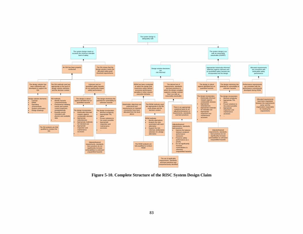
83
Figure 5-10. Complete Structure of the RISC System Design Claim
The system design is
adequately safe
The system design is as
safe as reasonably
practicable (ASARP)
The system design meets or
exceeds the minimum tolerable
level of safety
The ISA shows that the
design solution meets the
allocated safety goal/
threshold requirements.
An ISA has been properly
conducted
The ISA analysts are fully
qualified to conduct the
ISA
The ISA methods used are
appropriate to the level of
design solution definition
and the decision context
The design solution has
been sufficiently well
developed to support the
ISA
ISA methods:
Identify hazards
comprehensively
Characterize initiating
events and system
control responses
probabilistically
Quantify events
consistent with
physics and available
data
...
Design solution elements::
ConOps
DRMs
Operating
environments
System schematics
Design drawings
...
Design solution decisions
are
risk informed
RIDM has been conducted
to select the design that
maximizes safety without
excessive performance
penalties in other mission
execution domains
The tailored set of
requirements, standards,
and best practices to
which the design complies
supports a design solution
that is as safe as
reasonably practicable
The RIDM analysts are
fully qualified to conduct
RIDM
The RIDM methods used
are appropriate to the life
cycle phase and the
decision context
Stakeholder objectives are
understood and
requirements (or imposed
constraints) have been
allocated from the level
above
RIDM methods:
Identify alternatives
Analyze the risks
associated with each
alternative
Support the risk-
informed, deliberative
selection of a design
alternative
The set of applicable
requirements, standards,
and best practices was
comprehensively identified
There is an appropriate
analytical basis for all
adjustments/waivers to
requirements, standards,
and best practices
Adjusted/waived
requirements, standards,
best practices:
Improve the balance
between analyzed
performance
measures
Preserve safety
performance as a
priority
Do not significantly
increase
vulnerabilities to
unknown/
unquantified hazards
Appropriate historically-informed
defenses against unknown and
un-quantified safety hazards are
incorporated into the design
Adjusted/waived
requirements, standards,
best practices do not
significantly increase
vulnerabilities to unknown/
unquantified hazards
The design is robust
against identified but un-
quantified hazards
The design minimizes the
potential for vulnerability to
unknown hazards
The design incorporates:
Historically-informed
margins against
comparable stresses
Appropriate
redundancies
Appropriate materials
for intended use
Appropriate
inspection and
maintenance
accesses
...
The design incorporates:
Minimal complexity
Appropriate TRL
items
Proven solutions to
the extent possible
Appropriate
inspection and
maintenance
accesses
...
Allocated requirements
are consistent with
achievable safety
performance
Performance requirements
are consistent with the
performance commitments
developed during RIDM
Allocated requirements
have been negotiated
between the requirements
owner and the
organization responsible
for meeting the
requirements
Unknown and un-
quantified safety hazards
do not significantly impact
safety performance
Adjusted/waived
requirements, standards,
best practices do not
significantly increase
vulnerabilities to unknown/
unquantified hazards
The design is robust
against identified but un-
quantified hazards
The design minimizes the
potential for vulnerability to
unknown hazards
The design incorporates:
Historically-informed
margins against
comparable stresses
Appropriate
redundancies
Appropriate materials
for intended use
Appropriate
inspection and
maintenance
accesses
...
The design incorporates:
Minimal complexity
Appropriate TRL
items
Proven solutions to
the extent possible
Appropriate
inspection and
maintenance
accesses
...

84
Figure 5-11. Complete Structure of the RISC System Realization Claim
The as-built system is
adequately safe
The as-built system is as
safe as reasonably
practicable (ASARP)The as-built system meets
or exceeds the minimum
tolerable level of safety
The Risk Management
Plan (RMP) establishes a
CRM process that will
operate during system
realization to integrate
new information
developed during system
realization into the system
risk model
Per the RMP, system
safety performance will be
continuously monitored to
assure compliance with
allocated safety
requirements
System realization
decisions are risk informed
The RMP establishes a
CRM process that
supports risk-informed
selection of risk response
options
The Systems Engineering
Management Plan (SEMP)
establishes an opportunity
management process that
supports risk-informed
improvements to safety
during system realization
The RMP specifies that a
RIDM process will be
applied to system
realization decisions
The RIDM process will be
applied to:
Make/buy decisions
Selection of vendors
Selection of
manufacturing
process techniques
Development of
logistics
Development of test
protocols
...
System realization is
responsive to new
information
The RMP establishes a
CRM process that
continually seeks to
identify and manage
safety-related concerns
The SEMP establishes an
opportunity management
process that maintains
cognizance of state of the
art practices relevant to
system realization
The introduction of
potentially adverse
conditions during system
realization is minimized
The SEMP establishes
state-of-the-art system
realization processes that
minimize the introduction
of adverse conditions
System realization
processes include:
CRM
Quality assurance
Training
Records
management
Procurement
Auditing
Certifications and
approvals
...
Levied requirements that
affect safety are complied
with during system
realization
The SEMP specifies that
verification and validation
activities will be conducted
that objectively
demonstrate compliance
with requirements
affecting safety

85
Figure 5-12. Complete Structure of the RISC System Operation Claim
The as-operated
system is adequately
safe
The as-operated system is
as safe as reasonably
practicable (ASARP)
The as-operated system
meets or exceeds the
minimum tolerable level of
safety
The Risk Management
Plan (RMP) establishes a
CRM process that will
operate during system
operation to integrate new
information developed
during system realization
into the system risk model
Per the RMP, system
safety performance will be
continuously monitored to
assure compliance with
allocated safety
requirements
System operation
decisions are risk informed
The RMP establishes a
CRM process that
supports risk-informed
selection of risk response
options
The Systems Engineering
Management Plan (SEMP)
establishes an opportunity
management process that
supports risk-informed
improvements to safety
during system operation
The RMP specifies that a
RIDM process will be
applied to decisions during
system operation
The RIDM process will be
applied to:
Upgrades
Operational changes
...
System operation is
responsive to new
information
The RMP establishes a
CRM process that
continually seeks to
identify and manage
safety-related concerns
The SEMP establishes an
opportunity management
process that maintains
cognizance of state of the
art practices relevant to
system operation
The introduction of
potentially adverse
conditions during system
operation is minimized
The SEMP establishes
state-of-the-art operational
processes that minimize
the introduction of adverse
conditions
System operation
processes include:
CRM
Quality assurance
Training
Records
management
Inspections
Maintenence
Auditing
Certifications and
approvals
...
Levied requirements that
affect safety are complied
with during system
operation
The SEMP specifies that
flight readiness reviews
will be conducted that
objectively demonstrate
compliance with
requirements affecting
safety
The SEMP establishes an
accident precursor
analysis (APA) process
that analyzes operational
anomalies for potentially
risk-significant failure
mechanisms

86
5.5 Evaluating the RISC
Presentation of the RISC to the decision-maker is not a stopping point. The decision-maker
needs to consciously accept or reject the claims made by the RISC. This needs to be carried out
based on evaluation protocols. For each claim in the RISC, it is the task of the decision-maker to:
1. Understand the technical basis (i.e., evidence) behind the claim.
2. Question the technical basis of the claim to determine its validity.
3. Provide judgment as to adequacy of the claim.
In other words, to evaluate the RISC, the claims in the RISC are critically reviewed, thereby
making use of the collected evidence related to the safety of the system.
In questioning the technical basis of the RISC and judging its adequacy, it is important for the
reviewer to evaluate the RISC from a critical/skeptical viewpoint. The assumptions underlying
the RISC and the effectiveness of the processes implemented in accordance with the RISC
should be continually reviewed throughout every phase of the project.
It is a common and good practice for an evaluator to have one or more checklists for
determining whether the evidence is sufficient to support a claim. The checklist should not
mimic the structure of the RISC. Rather, it should be organized independently from the RISC so
as not to be constrained by the preconceptions and assumptions of the RISC provider. An
independent checklist will also tend to be generically applicable, as opposed to a RISC which
tends to be more application specific.
Two example checklists that would be appropriate for RISCs that pertain to NASA projects are
shown in Table 5-1 and Table 5-2. Each empty box in the checklists provides room for a grade
and for the evaluator’s comments.24 The grade is a means for ranking the degree to which each
item in the checklist has been addressed successfully by the safety case being evaluated. In
keeping with the general categories of activities depicted in Figure 4-1 through Figure 4-4, Table
5-1 applies to analyses and Table 5-2 to program controls. In the terminology of Section 5.2.2,
Table 5-1 provides an evaluation of direct or demonstrative arguments that a claim is satisfied,
whereas Table 5-2 provides backing or validating arguments.
Another example checklist that could be very useful to an evaluator of RISCs for NASA projects
is shown in Figure 5-13. This checklist is presented in a flow-down fashion starting from the top-
level claim (the system is safe). It has the advantage of explicitly showing how arguments based
on evidence support claims. 24 The format of the table can be changed to suit the reviewer’s needs. For example, it may be sufficient for some reviewers to enter one comment per row in Table 5-1 rather than one per cell.
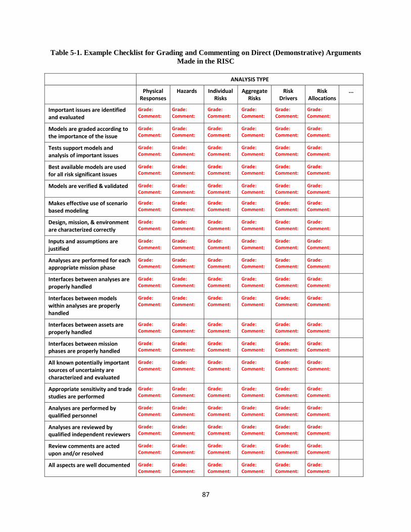
87
Table 5-1. Example Checklist for Grading and Commenting on Direct (Demonstrative) Arguments
Made in the RISC
ANALYSIS TYPE
Physical Responses
Hazards Individual Risks
Aggregate Risks
Risk Drivers
Risk Allocations
...
Important issues are identified and evaluated
Grade: Comment:
Grade: Comment:
Grade: Comment:
Grade: Comment:
Grade: Comment:
Grade: Comment:
Models are graded according to the importance of the issue
Grade: Comment:
Grade: Comment:
Grade: Comment:
Grade: Comment:
Grade: Comment:
Grade: Comment:
Tests support models and analysis of important issues
Grade: Comment:
Grade: Comment:
Grade: Comment:
Grade: Comment:
Grade: Comment:
Grade: Comment:
Best available models are used for all risk significant issues
Grade: Comment:
Grade: Comment:
Grade: Comment:
Grade: Comment:
Grade: Comment:
Grade: Comment:
Models are verified & validated Grade: Comment:
Grade: Comment:
Grade: Comment:
Grade: Comment:
Grade: Comment:
Grade: Comment:
Makes effective use of scenario based modeling
Grade: Comment:
Grade: Comment:
Grade: Comment:
Grade: Comment:
Grade: Comment:
Grade: Comment:
Design, mission, & environment are characterized correctly
Grade: Comment:
Grade: Comment:
Grade: Comment:
Grade: Comment:
Grade: Comment:
Grade: Comment:
Inputs and assumptions are justified
Grade: Comment:
Grade: Comment:
Grade: Comment:
Grade: Comment:
Grade: Comment:
Grade: Comment:
Analyses are performed for each appropriate mission phase
Grade: Comment:
Grade: Comment:
Grade: Comment:
Grade: Comment:
Grade: Comment:
Grade: Comment:
Interfaces between analyses are properly handled
Grade: Comment:
Grade: Comment:
Grade: Comment:
Grade: Comment:
Grade: Comment:
Grade: Comment:
Interfaces between models within analyses are properly handled
Grade: Comment:
Grade: Comment:
Grade: Comment:
Grade: Comment:
Grade: Comment:
Grade: Comment:
Interfaces between assets are properly handled
Grade: Comment:
Grade: Comment:
Grade: Comment:
Grade: Comment:
Grade: Comment:
Grade: Comment:
Interfaces between mission phases are properly handled
Grade: Comment:
Grade: Comment:
Grade: Comment:
Grade: Comment:
Grade: Comment:
Grade: Comment:
All known potentially important sources of uncertainty are characterized and evaluated
Grade: Comment:
Grade: Comment:
Grade: Comment:
Grade: Comment:
Grade: Comment:
Grade: Comment:
Appropriate sensitivity and trade studies are performed
Grade: Comment:
Grade: Comment:
Grade: Comment:
Grade: Comment:
Grade: Comment:
Grade: Comment:
Analyses are performed by qualified personnel
Grade: Comment:
Grade: Comment:
Grade: Comment:
Grade: Comment:
Grade: Comment:
Grade: Comment:
Analyses are reviewed by qualified independent reviewers
Grade: Comment:
Grade: Comment:
Grade: Comment:
Grade: Comment:
Grade: Comment:
Grade: Comment:
Review comments are acted upon and/or resolved
Grade: Comment:
Grade: Comment:
Grade: Comment:
Grade: Comment:
Grade: Comment:
Grade: Comment:
All aspects are well documented Grade: Comment:
Grade: Comment:
Grade: Comment:
Grade: Comment:
Grade: Comment:
Grade: Comment:

88
Table 5-2. Example Checklist for Grading and Commenting on Backing (Validating) Arguments
Made in the RISC
PROGRAMMATIC CONTROL
Plans related to programmatic controls are comprehensively and clearly documented. Grade: Comment:
Management will actively promote an environment within which design opportunities for improving safety without incurring unreasonable cost, schedule, and technical impacts are sought out and implemented during each project phase.
Grade: Comment:
Protocols are in place that will promote effective and timely communication among design teams from different organizations working on different parts of the system.
Grade: Comment:
Configuration management processes will be in place to ensure that modifications to the design are kept up to date and that everyone is working from the same drawings and specifications.
Grade: Comment:
There is a process for ensuring that decisions relating to design, realization, and operation will be informed by best practices and by lessons learned from previous projects.
Grade: Comment:
There is a process for verifying that all requirements, codes, and standards related to system design, realization, and operation that have been designated as being important to safety will be satisfied, and continue to be satisfied as changes occur.
Grade: Comment:
Quality assurance plans and processes are in compliance with SAE Aerospace Standard (AS) 9100 and audits and reviews will be conducted to ensure that actual practice is in compliance with the plans.
Grade: Comment:
Training programs will be in place where needed to help employees at NASA and NASA’s suppliers to gain the necessary knowledge and skill to fulfill the mission. Where appropriate, the personnel assigned to each task will be certified to perform that task.
Grade: Comment:
The procurement process will utilize a risk-informed decision methodology to select between supplier alternatives.
Grade: Comment:
Unanticipated events and anomalies occurring during system operation will be evaluated to determine whether they could be considered as precursors to an accident. If so, this information will be used to determine whether the risk models need to be modified and whether additional controls are needed.
Grade: Comment:
A risk-informed approach to maintenance, inspections, and audits will be implemented. The ordering of activities in these areas will be prioritized so that actions that are important to safety risk are conducted first and most thoroughly.
Grade: Comment:
A risk-informed approach to training and certification of crew, mission control personnel, and launch control personnel will be implemented. Operating procedures, training, and certification will be prioritized to emphasize areas and skills that are needed to minimize safety risks
Grade: Comment:
The example checklists provided herein are for illustration purposes only. They are not
intended to replace the evaluator’s judgment in formulating questions to be addressed during
the evaluation process.
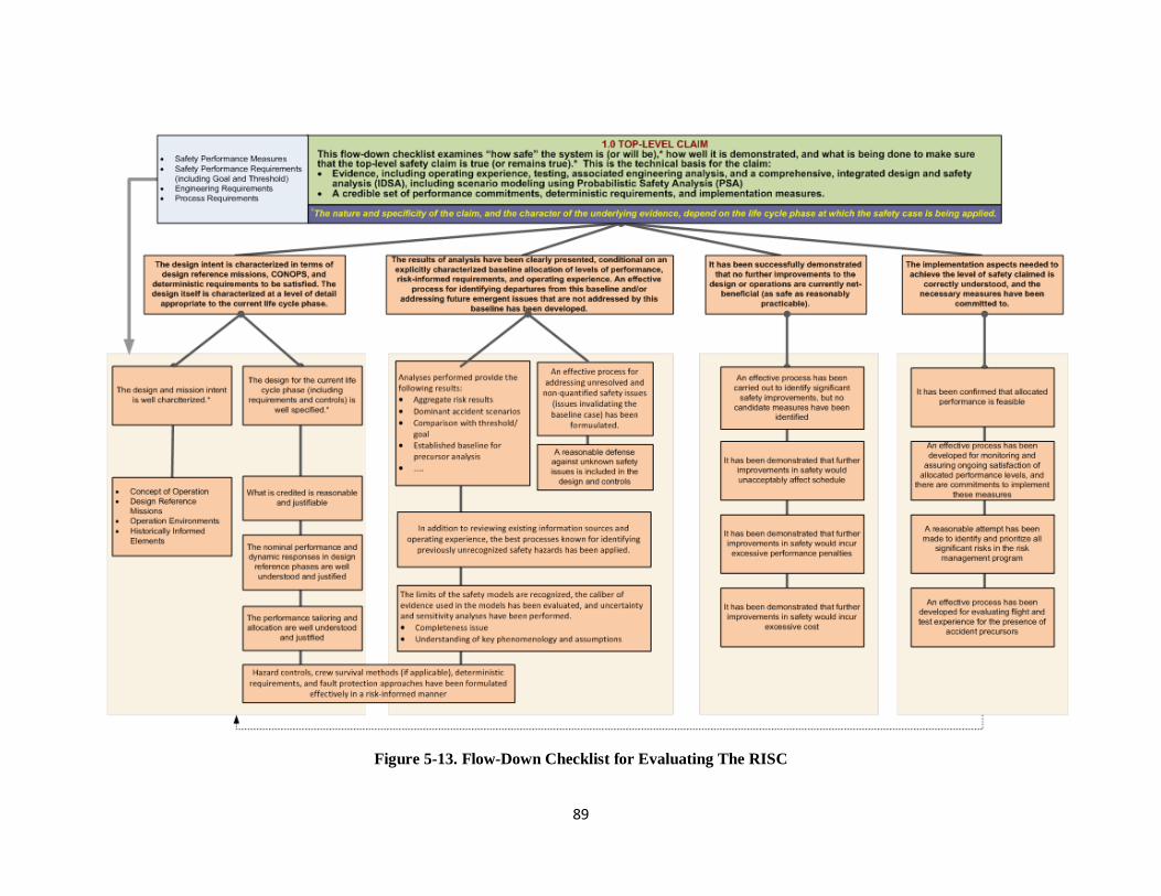
89
Figure 5-13. Flow-Down Checklist for Evaluating The RISC

90

91
6 Conclusions
This volume of the NASA System Safety Handbook presents a System Safety Framework that
provides a coherent structure for organizing system safety activities towards the achievement
and demonstration of safety throughout the system life cycle. Within the framework, system
safety activities are organized around the accomplishment of clearly stated safety objectives
that collectively define adequate safety for the system, and are communicated to decision
makers via a risk-informed safety case that provides a compelling, comprehensible and valid
argument, supported by evidence, that the system is or will be adequately safe for a given
application in a given environment.
System safety, which traditionally has focused on the conduct of safety analyses such as hazard
analysis and PRA, is broadened in this handbook to entail more than just analysis; it is a holistic,
integrated discipline that informs decision making throughout the system life cycle. It brings
together qualitative and quantitative analysis, historical experience, adherence to standards
and best practices, and compliance with requirements to ensure that safety is properly
considered whenever decisions are made that affect safety. As such, system safety personnel
must actively collaborate with systems engineering and program control organizations to
influence decision making during concept development, design, system realization, and system
operation, with the objective that the system meets or exceeds the minimum tolerable level of
safety, that it is as safe as reasonably practicable, and for systems that will be reused, that a
plausible plan is in place for continuous safety improvement in accordance with increasing
minimum tolerable levels of safety over time.
The assurance argument that the system is safe is documented in the risk-informed safety case
(RISC), which brings together all of the key pieces of system safety into a single reviewable
document. At major milestones such as Key Decision Points (KDPs), the RISC provides decision
makers with a coherent means of evaluating the safety of the system. Informed by this
evaluation, a decision can be made to either proceed in the system life cycle or not. If safety is
found lacking in one or more particulars, the risk-informed safety case supports the
identification of additional measures that must be implemented before the system continues to
the next life cycle phase.

92

93
7 References
1. NASA. NPR 8715.3C, NASA General Safety Program Requirements, Washington, DC. 2008.
2. NASA. NPR 7123.1A, NASA Systems Engineering Processes and Requirements, Washington,
DC. 2007.
3. NASA. NPD 8700.1, NASA Policy for Safety and Mission Success, Washington, DC. 2008.
4. NASA. NPR 8705.2B, Human-Rating Requirements for Space Systems, Washington, DC. 2008.
5. NASA. NPR 8000.4A, Agency Risk Management Procedural Requirements, Washington, DC.
2008.
6. NASA. NASA/SP-2011-3422, NASA Risk Management Handbook, Washington, DC. 2011.
7. DoD. MIL-STD-882D, Standard Practice for System Safety, Washington, DC. 2000.
8. NASA. Decision Memorandum for the Administrator, “Agency’s Safety Goals and Thresholds
for Crew Transportation Missions to the International Space Station (ISS)”, Washington, DC.
2011.
9. U.S. Code of Federal Regulations, 10 CFR 20, Standards for Protection Against Radiation,
Washington, DC. 1991.
10. Parliament of the United Kingdom, Health and Safety at Work etc. Act, London, UK. 1974.
11. Federal Aviation Administration (FAA). FAA System Safety Handbook, Washington, DC. 2000.
12. NASA. NPR 7120.5D, NASA Space Flight Program and Project Management Requirements,
Washington, DC. 2007.
13. NASA. NASA/SP-2011-3423, NASA Accident Precursor Analysis Handbook, Washington, DC.
2011.
14. Columbia Accident Investigation Board, “Columbia Accident Investigation Board Report,”
Washington, DC. 2003.

94
15. U.K. Ministry of Defence, Defence Standard 00-56, “Safety Management Requirements for
Defence Systems,” London, UK. 2007.
16. Holloway, C. M., “Safety Case Notations: Alternatives for the Non-Graphically Inclined?” 3rd
IET International Conference on System Safety. 2008.
17. Bishop, P. and Bloomfield, R., “A Methodology for Safety Case Development,” Safety-Critical
Systems Symposium, Birmingham, UK. 1998.
18. Duane, J. T., “Learning Curve Approach to Reliability Monitoring,” IEEE Transactions on
Aerospace, Vol. 2, No.2, 1964.
19. Saleh, J., and J. Castet, “Spacecraft Reliability and Multi-State Failures, A Statistical
Approach,” John Wiley & Sons, 2011.
20. Center for Advanced Life Cycle Engineering (CALCE), “Position Paper on Risks to High-
Reliability Electronics and Associated Hardware from Pure Tin Coatings,” University of
Maryland, Revision 2, July 2002.
21. Hamlin, T., et al., “Shuttle Risk Progression: Use of the Shuttle PRA to Show Reliability
Growth,” AIAA SPACE Conference & Exposition, September 2011.
22. Chang, I-S., “Space Launch Vehicle Reliability,” The Aerospace Corporation, 2001.
23. ASAP. Annual Report for 2011, Washington, DC. 2011.
24. British Court of Appeal, “Edwards v. National Coal Board,” UK. 1949.
25. NASA. NASA-STD-7009, Standard for Models and Simulations, Washington, DC. 2008.
26. NASA. NPD 1000.0A, NASA Governance and Strategic Management Handbook, Washington,
DC. 2008.
27. SAE. AS9100, “Quality Systems - Aerospace - Model for Quality Assurance in Design,
Development, Production, Installation and Servicing,” Warrendale, PA. 1999.
28. NASA. NASA/SP-2011-3421, Probabilistic Risk assessment Procedures Guide for NASA
Managers and Practitioners, Second Edition, Washington, DC. 2011.
29. RAC Publication, CPE, Reliability Toolkit: Commercial Practices Edition.

95
30. RADC-TR-77-287, A Redundancy Notebook, In-House Report, December 1977. Available
through National Technical Information Services, Order No. AD-A050-837.
31. MIL-HDBK-217F, “Reliability Prediction of Electronic Equipment,” December 1991.
32. Naval Surface Warfare Center, “Handbook of Reliability for Mechanical Equipment,” NSWC-
06/LE10, January 2006.
33. Kirwan, B., “A Guide to Practical Human Reliability Assessment,” CRC Press, 1994.
34. Pagani, L. P., “On the Quantification of Safety Margins,” PhD Dissertation, Massachusetts
Institute of Technology, September 2004.
35. Mettas, A., “Reliability Allocation and Optimization for Complex Systems,” Proceedings of
the Annual Reliability and Maintainability Symposium, 2000.
36. Dugan, J. B., “Fault Tree Analysis of Computer-Based Systems,” Reliability and
Maintainability Symposium, January 2003.
37. Rushby, J., “Formalism in Safety Cases,” Making Systems Safer: Proceedings of the
Eighteenth Safety-Critical Systems Symposium, pp. 3-17, Bristol, UK. 2010.
38. Attwood, K., et al., “GSN Community Standard Version 1,” Origin Consulting (York) Limited,
November 2011.

96

97
Appendix A: Acronyms
ALARA As Low as Reasonably Achievable
ALARP As Low as Reasonably Practicable
APA Accident Precursor Analysis
AS Aerospace Standard
ASAP Aerospace Safety Advisory Panel
ASARP As Safe as Reasonably Practicable
CAIB Columbia Accident Investigation Board
CALCE Center for Advanced Life Cycle Engineering
CCDF Complementary Cumulative Distribution Function
CDR Critical Design Review
CFD Computational Fluid Dynamics
ConOps Concept of operations
CRM Continuous Risk Management
DoD Department of Defense
FAA Federal Aviation Administration
FM Fault Management
FMEA Failure Modes and Effects Analysis
GSN Goal Structuring Notation
HAZOP Hazard and Operability Study
ISA Integrated Safety Analysis
ISS International Space Station
KDP Key Decision Point

98
LEO Low Earth Orbit
LOC Loss of Crew
LOM Loss of Mission
LOV Loss of Vehicle
MMOD Micro-Meteoroid and Orbital Debris
NASA National Aeronautics and Space Administration
NPD NASA Policy Directive
NPR NASA Procedural Requirement
PBS Product Breakdown Structure
PDF Probability Density Function
PDR Preliminary Design Review
PRA Probabilistic Risk Assessment
PSA Probabilistic Safety Analysis
QA Quality Assurance
RIDM Risk-Informed Decision Making
RISC Risk-Informed Safety Case
RM Risk Management
RMP Risk Management Plan
SAE Society of Automotive Engineers
SE Systems Engineering
SEMP Systems Engineering Management Plan
SIR System Integration Review
SSTP System Safety Technical Plan
STI Scientific and Technical Information
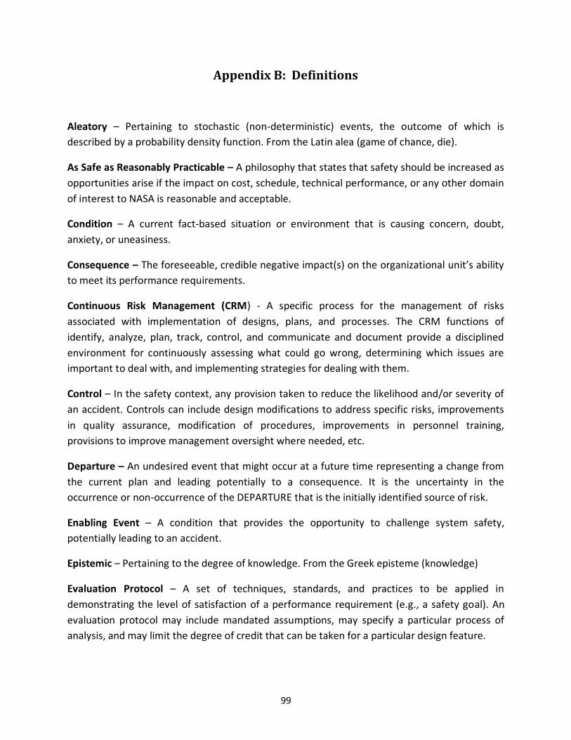
99
Appendix B: Definitions
Aleatory – Pertaining to stochastic (non-deterministic) events, the outcome of which is
described by a probability density function. From the Latin alea (game of chance, die).
As Safe as Reasonably Practicable – A philosophy that states that safety should be increased as
opportunities arise if the impact on cost, schedule, technical performance, or any other domain
of interest to NASA is reasonable and acceptable.
Condition – A current fact-based situation or environment that is causing concern, doubt,
anxiety, or uneasiness.
Consequence – The foreseeable, credible negative impact(s) on the organizational unit’s ability
to meet its performance requirements.
Continuous Risk Management (CRM) - A specific process for the management of risks
associated with implementation of designs, plans, and processes. The CRM functions of
identify, analyze, plan, track, control, and communicate and document provide a disciplined
environment for continuously assessing what could go wrong, determining which issues are
important to deal with, and implementing strategies for dealing with them.
Control – In the safety context, any provision taken to reduce the likelihood and/or severity of
an accident. Controls can include design modifications to address specific risks, improvements
in quality assurance, modification of procedures, improvements in personnel training,
provisions to improve management oversight where needed, etc.
Departure – An undesired event that might occur at a future time representing a change from
the current plan and leading potentially to a consequence. It is the uncertainty in the
occurrence or non-occurrence of the DEPARTURE that is the initially identified source of risk.
Enabling Event – A condition that provides the opportunity to challenge system safety,
potentially leading to an accident.
Epistemic – Pertaining to the degree of knowledge. From the Greek episteme (knowledge)
Evaluation Protocol – A set of techniques, standards, and practices to be applied in
demonstrating the level of satisfaction of a performance requirement (e.g., a safety goal). An
evaluation protocol may include mandated assumptions, may specify a particular process of
analysis, and may limit the degree of credit that can be taken for a particular design feature.

100
Hazard – A state or a set of conditions, internal or external to a system, that has the potential
to cause harm. Examples of hazards include materials, energy sources, or operational practices
that in uncontrolled situations can lead to scenarios that could produce death, injury, illness,
equipment loss or damage, or damage to a protected environment.
Hazards Analysis – An application of systematic and replicable methods to identify and
understand hazards, and to characterize the risk of mishaps that involve hazards. Risks originate
from hazards – the absence of a hazard implies a freedom from the associated risk.
Initiating Event – A departure from a desired operational envelope to a system state where a
control response is required either by human, software, or machine intervention.
Key Decision Point – The event at which the Decision Authority determines the readiness of a
program/project to progress to the next phase of the life cycle (or to the next KDP)
Model – A description or representation of a system, entity, phenomenon, or process.
Objectives Hierarchy – An arrangement where objectives are decomposed into a set of
quantifiable sub-objectives, each of which is implied by the top-level objective
Performance Measure – A quantifiable attribute of a decision alternative, used to support
decision-making. Performance measures are typically defined for all mission execution domains
and for institutional performance. For purposes of System Safety at NASA, performance
measures include metrics related to human safety, asset protection, and environmental
protection.
Performance Requirements – A value of a performance measure to be achieved by an
organizational unit’s work that has been agreed-upon to satisfy the needs of the next higher
organizational level. [NPR 8000.4A]
Probabilistic Safety Analysis – A structured, probabilistic treatment of scenarios, likelihoods,
consequences using a graded approach. Within this approach, the word “probabilistic” refers
explicitly to a Bayesian treatment of uncertainty.
Probabilistic Thinking – A process of explicitly factoring in the quality of our state-of-knowledge
into models, analysis, and decision-making. This process recognizes limits in all areas of the
System Safety assessment, including: completeness of hazard identification, understanding of
the phenomenology, the caliber of evidence supporting the RISC, and weighing the possibility of
adverse outcomes in decision-making.
Risk – The potential for shortfalls, which may be realized in the future, with respect to achieving
explicitly stated performance requirements. Risk is characterized by a set of triplets: 1) the
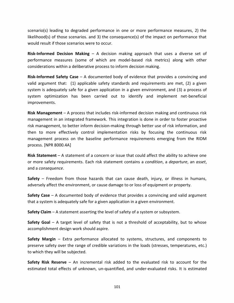
101
scenario(s) leading to degraded performance in one or more performance measures, 2) the
likelihood(s) of those scenarios. and 3) the consequence(s) of the impact on performance that
would result if those scenarios were to occur.
Risk-Informed Decision Making – A decision making approach that uses a diverse set of
performance measures (some of which are model-based risk metrics) along with other
considerations within a deliberative process to inform decision making.
Risk-Informed Safety Case – A documented body of evidence that provides a convincing and
valid argument that: (1) applicable safety standards and requirements are met, (2) a given
system is adequately safe for a given application in a given environment, and (3) a process of
system optimization has been carried out to identify and implement net-beneficial
improvements.
Risk Management – A process that includes risk-informed decision making and continuous risk
management in an integrated framework. This integration is done in order to foster proactive
risk management, to better inform decision-making through better use of risk information, and
then to more effectively control implementation risks by focusing the continuous risk
management process on the baseline performance requirements emerging from the RIDM
process. [NPR 8000.4A]
Risk Statement – A statement of a concern or issue that could affect the ability to achieve one
or more safety requirements. Each risk statement contains a condition, a departure, an asset,
and a consequence.
Safety – Freedom from those hazards that can cause death, injury, or illness in humans,
adversely affect the environment, or cause damage to or loss of equipment or property.
Safety Case – A documented body of evidence that provides a convincing and valid argument
that a system is adequately safe for a given application in a given environment.
Safety Claim – A statement asserting the level of safety of a system or subsystem.
Safety Goal – A target level of safety that is not a threshold of acceptability, but to whose
accomplishment design work should aspire.
Safety Margin – Extra performance allocated to systems, structures, and components to
preserve safety over the range of credible variations in the loads (stresses, temperatures, etc.)
to which they will be subjected.
Safety Risk Reserve – An incremental risk added to the evaluated risk to account for the
estimated total effects of unknown, un-quantified, and under-evaluated risks. It is estimated

102
from analysis of historical experience with similar technologies taking into account the
complexity of the system, the degree to which new technology is being used, and the degree to
which new operating environments are being introduced.
Safety Threshold – Criteria for risk acceptance decisions; acceptance of risks exceeding
threshold values requires elevation of the risk to the next higher level in the organization.
Scenario – A sequence of credible events that specifies the evolution of a system or process
from a given state to a future state. In the context of risk management, scenarios are used to
identify the ways in which a system or process in its current state can evolve to an undesirable
state.
Sensitivity Study – The study of how the variation in the output of a model can be apportioned
to different sources of variation in the model input and parameters.
Success Path – A scenario wherein the chain of events leads to an acceptable outcome, and is
based upon the complement of system design attributes that work together to do a particular
job.
System Safety – A disciplined, systematic process for the consideration of risks resulting from
hazards that can affect humans, the environment, or mission assets. Per NPR 8715.3C, System
Safety is the rational pursuit of safety within a systems perspective, where the degree of
“safety” is to be understood in the context of a particular application. The system safety
process does not expect to attain absolute safety, but strives to attain a degree of safety that
fulfills obligations to the at-risk communities and addresses Agency priorities.
Uncertainty – An imperfect state of knowledge or a physical variability resulting from a variety
of factors including, but not limited to, lack of knowledge, applicability of information, physical
variation, randomness or stochastic behavior, indeterminacy, judgment, and approximation.


National Aeronautics and Space Administration
NASA Headquarters
Office of Safety and Mission Assurance
300 E Street SW
Washington, DC 20546-0001