nasa electric aircraft test bed (neat) development plan ... · nasa/tm—2016-219085 2 electric...
TRANSCRIPT

Rodger W. DysonGlenn Research Center, Cleveland, Ohio
NASA Electric Aircraft Test bed (NEAT) Development Plan—Design, Fabrication, Installation
NASA/TM—2016-219085
July 2016
https://ntrs.nasa.gov/search.jsp?R=20160010440 2019-06-29T06:46:13+00:00Z
NASA STI Program . . . in Profi le
Since its founding, NASA has been dedicated to the advancement of aeronautics and space science. The NASA Scientifi c and Technical Information (STI) Program plays a key part in helping NASA maintain this important role.
The NASA STI Program operates under the auspices of the Agency Chief Information Offi cer. It collects, organizes, provides for archiving, and disseminates NASA’s STI. The NASA STI Program provides access to the NASA Technical Report Server—Registered (NTRS Reg) and NASA Technical Report Server—Public (NTRS) thus providing one of the largest collections of aeronautical and space science STI in the world. Results are published in both non-NASA channels and by NASA in the NASA STI Report Series, which includes the following report types: • TECHNICAL PUBLICATION. Reports of
completed research or a major signifi cant phase of research that present the results of NASA programs and include extensive data or theoretical analysis. Includes compilations of signifi cant scientifi c and technical data and information deemed to be of continuing reference value. NASA counter-part of peer-reviewed formal professional papers, but has less stringent limitations on manuscript length and extent of graphic presentations.
• TECHNICAL MEMORANDUM. Scientifi c
and technical fi ndings that are preliminary or of specialized interest, e.g., “quick-release” reports, working papers, and bibliographies that contain minimal annotation. Does not contain extensive analysis.
• CONTRACTOR REPORT. Scientifi c and technical fi ndings by NASA-sponsored contractors and grantees.
• CONFERENCE PUBLICATION. Collected papers from scientifi c and technical conferences, symposia, seminars, or other meetings sponsored or co-sponsored by NASA.
• SPECIAL PUBLICATION. Scientifi c,
technical, or historical information from NASA programs, projects, and missions, often concerned with subjects having substantial public interest.
• TECHNICAL TRANSLATION. English-
language translations of foreign scientifi c and technical material pertinent to NASA’s mission.
For more information about the NASA STI program, see the following:
• Access the NASA STI program home page at http://www.sti.nasa.gov
• E-mail your question to [email protected] • Fax your question to the NASA STI
Information Desk at 757-864-6500
• Telephone the NASA STI Information Desk at 757-864-9658 • Write to:
NASA STI Program Mail Stop 148 NASA Langley Research Center Hampton, VA 23681-2199

Rodger W. DysonGlenn Research Center, Cleveland, Ohio
NASA Electric Aircraft Test bed (NEAT) Development Plan—Design, Fabrication, Installation
NASA/TM—2016-219085
July 2016
National Aeronautics andSpace Administration
Glenn Research CenterCleveland, Ohio 44135
Acknowledgments
This work was sponsored by the Advanced Air Vehicles Program, Advanced Air Transport Technology Project,Hybrid Gas-Electric Power Subproject at the NASA Glenn Research Center.
Available from
Trade names and trademarks are used in this report for identifi cation only. Their usage does not constitute an offi cial endorsement, either expressed or implied, by the National Aeronautics and
Space Administration.
Level of Review: This material has been technically reviewed by technical management.
This report is a formal draft or working paper, intended to solicit comments and
ideas from a technical peer group.
This report contains preliminary fi ndings, subject to revision as analysis proceeds.
NASA STI ProgramMail Stop 148NASA Langley Research CenterHampton, VA 23681-2199
National Technical Information Service5285 Port Royal RoadSpringfi eld, VA 22161
703-605-6000
This report is available in electronic form at http://www.sti.nasa.gov/ and http://ntrs.nasa.gov/
Does this apply?
Does this apply?
Does this apply?

NASA/TM—2016-219085 iii
Contents Summary ....................................................................................................................................................... 1 Purpose of the Test Bed ................................................................................................................................ 1 Electric Aircraft Test Bed Capability in the United States ........................................................................... 2 Building Details and Location ...................................................................................................................... 3
Facility and Test Bed Location ............................................................................................................... 3 Facility and Test Bed Interfaces ............................................................................................................. 4
Development Steps for Advancing Powertrain Technology ......................................................................... 5 Phased Powertrain Development ............................................................................................................ 5
Phase 1: State-of-the-Art Testing (FY16 to FY17) .......................................................................... 6 Phase 2: Ambient Research Hardware Testing (FY18 to FY19) ..................................................... 6 Phase 3: Cryogenically Cooled Research Hardware Testing (FY20 to FY21) ................................ 6 Phase 4: Powertrain Thermal Management Research Hardware Testing (FY21 to FY22) ............. 6
Future Growth ........................................................................................................................................ 6 Detailed Concept Development .................................................................................................................... 7
Electrical and Mechanical Concept ........................................................................................................ 7 Test Bed Components ............................................................................................................................ 8
Mechanical Configuration ............................................................................................................... 9 Electrical Configuration ................................................................................................................. 10 System Geometry and Network Topology ..................................................................................... 15 Test Plan for Fiscal Year 2016 ....................................................................................................... 15 Scientific Development Goals for Fiscal Year 2017 ..................................................................... 17 Scientific Development Goals for Fiscal Years 2018 and 2019 .................................................... 17 Scientific Development Goals for Fiscal Years 2020 and 2021 .................................................... 18 Scientific Development Goals for Fiscal Year 2022 ..................................................................... 18
Conclusions ................................................................................................................................................. 19 Appendix—Fiscal Year 2016 Test Plan for a Single-String Configuration ................................................ 21 References ................................................................................................................................................... 25
List of Figures Figure 1.—Exterior of NASA Electric Aircraft Test bed (NEAT). LH2, liquid hydrogen. .......................... 3 Figure 2.—Interior of NASA Electric Aircraft Test bed (NEAT). ............................................................... 3 Figure 3.—Interior layout of NASA Electric Aircraft Test bed (NEAT). .................................................... 4 Figure 4.—NASA Electric Aircraft Test bed (NEAT) initial configuration. AC, alternating current; DC,
direct current. .......................................................................................................................................... 8 Figure 5.—NASA Electric Aircraft Test bed (NEAT) reconfigurable test bed example (Gulfstream G150
configuration). ........................................................................................................................................ 8 Figure 6.—NASA Electric Aircraft Test bed (NEAT) modular motor mounts (Gulfstream G150
configuration). (a) 125-kW Parker motor/dynamometer. (b) 1-MW pancake motor/dynamometer/generator (0.6 m in diameter by 0.6 m in length). (c) 10-MW pancake motor/generator (1.3 m in diameter by 0.6 m in length). (d) 1-MW wingtip mount. ................................ 9
Figure 7.—Wing modular construction (Gulfstream G150 configuration). (a) Top view. (b) Bottom view. ................................................................................................................................................................ 9
Figure 8.—Half-wing assembly (Gulfstream G150 configuration). DC, direct current. .............................. 9 Figure 9.—Single-string motor pair. CAN, Controller Area Network. (a) Schematic. (b) Physical layout.
.............................................................................................................................................................. 10 Figure 10.—Speed/torque performance curves. (a) For electric motors. (b) For aircraft turbofans during
takeoff and cruise. ................................................................................................................................ 11
NASA/TM—2016-219085 iv
Figure 11.—Schematic of 16 single-string propulsors. CAN, Controller Area Network; EMI, electromagnetic interference. ............................................................................................................... 12
Figure 12.—Physical layout of powertrain. GVM, global vehicle motor; GC, generator convertor; DC, direct current; EC, engine convertor; MC, motor convertor; FC, fan convertor; AC, alternating current. .................................................................................................................................................. 13
Figure 13.—Physical layout of command and data management system. GC, generator convertor; DC, direct current; FG, fan generator; EC, engine convertor; AC, alternating current. .............................. 14
Figure 14.—Major test components. (a) Power supply. (b) Motor pair. (c) Outside chiller. ...................... 15 Figure 15.—NASA Electric Aircraft Test bed (NEAT) single-string control cabinet. For more
information, see Altium (2016). (a) Sheet 1. ........................................................................................ 21 Figure 16.—NASA Electric Aircraft Test bed (NEAT) single-string inverter/motor. For more information,
see Altium (2016). (a) Sheet 1. ............................................................................................................. 23
List of Tables Table I.—NASA Electric Aircraft Test Beds ............................................................................................... 2 Table II.—Powertrain components that are planned to be supported ........................................................... 7 Table III.—Parker Hannifin Corporation Fan Motor Properties................................................................. 10 Table IV.—Rinehart Motion Control System Motor Controller Specifications ......................................... 11 Table V.—Test Matrix For Single-Strand Propulsor .................................................................................. 16 Table VI.—Key Task List for Fiscal Year 2017 ......................................................................................... 17 Table VII.—Key Task List for Fiscal Years 2018 and 2019 ...................................................................... 17 Table VIII.—Key Task List for Fiscal Years 2020 and 2021 ..................................................................... 18 Table IX.—Key Task List for Fiscal Year 2022 ......................................................................................... 18

NASA/TM—2016-219085 1
NASA Electric Aircraft Test bed (NEAT) Development Plan— Design, Fabrication, Installation
Rodger W. Dyson
National Aeronautics and Space Administration Glenn Research Center Cleveland, Ohio 44135
Summary
As large airline companies compete to reduce emissions, fuel burn, noise, and maintenance costs, NASA expects that more of their aircraft systems will shift from using turbofan propulsion, pneumatic bleed power, and hydraulic actuation—to using electrical motor propulsion, generator power, and electrical actuation. This requires new flight-weight and flight-efficient powertrain components, fault-tolerant power management, and electromagnetic interference mitigation technologies. Moreover, initial studies indicate that some combination of ambient and cryogenic thermal management and bus voltages that are high in comparison to the state of practice will be required to achieve a net system benefit. Developing all of these powertrain technologies within a realistic aircraft architectural geometry and under realistic operational conditions requires a unique electric aircraft test bed. This report details the development plan for a unique test bed, with a reconfigurable architecture, that industry and Government can utilize to further mature electric aircraft technologies. This test bed is intended to be complementary to other capabilities within NASA, industry, and academia.
Purpose of the Test Bed
NASA’s Electric Aircraft Test bed (NEAT) is being developed to enable end-to-end development and testing of a full-scale electric aircraft powertrain. The primary purpose of the test bed is to enable the high-power ambient and cryogenic flight-weight power system testing that is required for the develop-ment of the following components to Technology Readiness Level (TRL) 6:
High-voltage bus architecture—Insulation and geometry; 600 to 4500 V High-power megawatt inverters and rectifiers—Commercial, in-house, and NASA Research
Announcement (NRA) development High-power megawatt motors and generators—Commercial, in-house, and NRA development System communication—Aircraft Controller Area Network (CAN), Ethernet, and fiber optics System electromagnetic interference (EMI) mitigation and standards—Shielding; DOD–160
(RTCA, Inc., 2010) and MIL–STD–461 (Department of Defense, 2015) System fault protection—Fuse, circuit breaker, and current limiter System thermal management—Active/passive, ambient/cryogenic, and distributed/mixed The Advanced Air Vehicle Program, Advanced Air Transport Technology Project, Hybrid Gas-
Electric Power Subproject requires this test bed to meet the subproject’s technology development goals for future single-aisle electric aircraft. This test facility will provide a path for full-scale powertrain component development and demonstration prior to flight.
NASA/TM—2016-219085 2
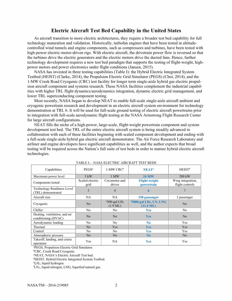
Electric Aircraft Test Bed Capability in the United States As aircraft transition to more-electric architectures, they require a broader test bed capability for full
technology maturation and validation. Historically, turbofan engines that have been tested in altitude-controlled wind tunnels and engine components, such as compressors and turbines, have been tested with high-power electric-motor-driven rigs. With electric aircraft, the drivetrain power flow is reversed so that the turbines drive the electric generators and the electric motors drive the ducted fans. Hence, further technology development requires a new test bed paradigm that supports the testing of flight-weight, high-power motors and power electronics under flight conditions (Jansen, 2015).
NASA has invested in three testing capabilities (Table I): the Hybrid Electric Integrated System Testbed (HEIST) (Clarke, 2014), the Propulsion Electric Grid Simulator (PEGS) (Choi, 2014), and the 1-MW Creek Road Cryogenic (CRC) test facility for longer term single-aisle hybrid gas electric propul-sion aircraft component and systems research. These NASA facilities complement the industrial capabil-ities with higher TRL flight dynamics/aerodynamics integration, dynamic electric grid management, and lower TRL superconducting component testing.
Most recently, NASA began to develop NEAT to enable full-scale single-aisle aircraft ambient and cryogenic powertrain research and development in an electric aircraft system environment for technology demonstration at TRL 6. It will be used for full-scale ground testing of electric aircraft powertrains prior to integration with full-scale aerodynamic flight testing at the NASA Armstrong Flight Research Center for large aircraft configurations.
NEAT fills the niche of a high-power, large-scale, flight-weight powertrain component and system development test bed. The TRL of the entire electric aircraft system is being steadily advanced in collaboration with each of these facilities beginning with scaled component development and ending with a full-scale single-aisle hybrid gas electric aircraft demonstrator. The Air Force Research Laboratory and airliner and engine developers have significant capabilities as well, and the author expects that broad testing will be required across the Nation’s full suite of test beds in order to mature hybrid electric aircraft technologies.
TABLE I.—NASA ELECTRIC AIRCRAFT TEST BEDS
Capabilities PEGSa 1-MW CRCb NEATc HEISTd
Maximum power level 3 kW 1 MW 24 MW 200 kW
Components tested Scaled electric
grid Cryomotor and
drives Flight-weight powertrain
Wing integration, flight controls
Technology Readiness Level (TRL) demonstrated
3 4 6 7
Aircraft size NA NA 150 passenger 2 passenger
Cryogenic No e500-gal LH2
(1.9 ML)
f3000-gal LH2, LN, LNG (11.4 ML)
No
Chiller No No Yes No Heating, ventilation, and air conditioning (HVAC)
No No Yes No
Aerodynamic loading No No No Yes Thermal No Yes Yes Yes Control No No Yes Yes Atmospheric pressure No No No No Takeoff, landing, and cruise operation
Yes NA Yes Yes
aPEGS, Propulsion Electric Grid Simulator. bCRC, Creek Road Cryogenic. cNEAT, NASA’s Electric Aircraft Test bed. dHEIST, Hybrid Electric Integrated System Testbed. eLH2, liquid hydrogen. fLN2, liquid nitrogen; LNG, liquefied natural gas.
NASA/TM—2016-219085 3
Furthermore, it is important to note that this test bed is the key to understanding how actual individual research hardware components contribute to the net performance benefit of the overall aircraft. For example, a cryogenic motor located next to an ambient inverter could suffer thermal losses not identified from motor testing alone, or a high dV/dt pulse-width-modulation (PWM) switching rate in the inverter could damage a low-impedance motor. These system interactions can only be tested in a NEAT-like environment that offers full-scale powertrain system testing under controlled flight scenarios.
Building Details and Location
Facility and Test Bed Location
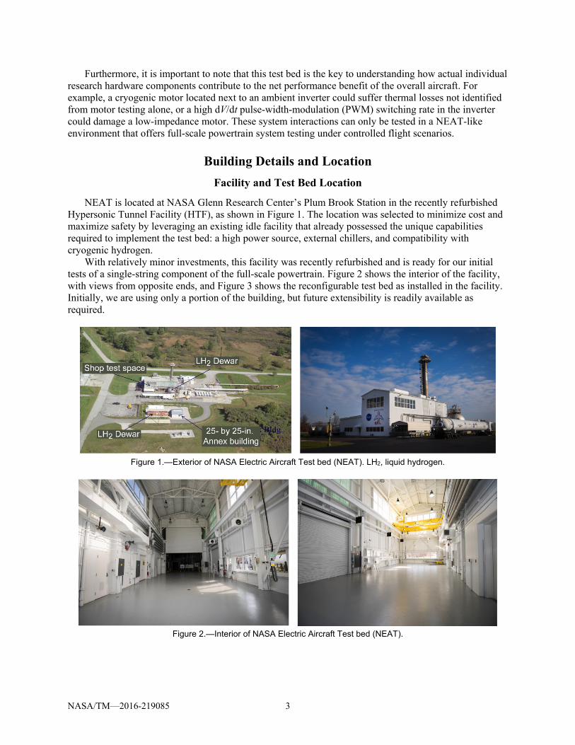
NEAT is located at NASA Glenn Research Center’s Plum Brook Station in the recently refurbished Hypersonic Tunnel Facility (HTF), as shown in Figure 1. The location was selected to minimize cost and maximize safety by leveraging an existing idle facility that already possessed the unique capabilities required to implement the test bed: a high power source, external chillers, and compatibility with cryogenic hydrogen.
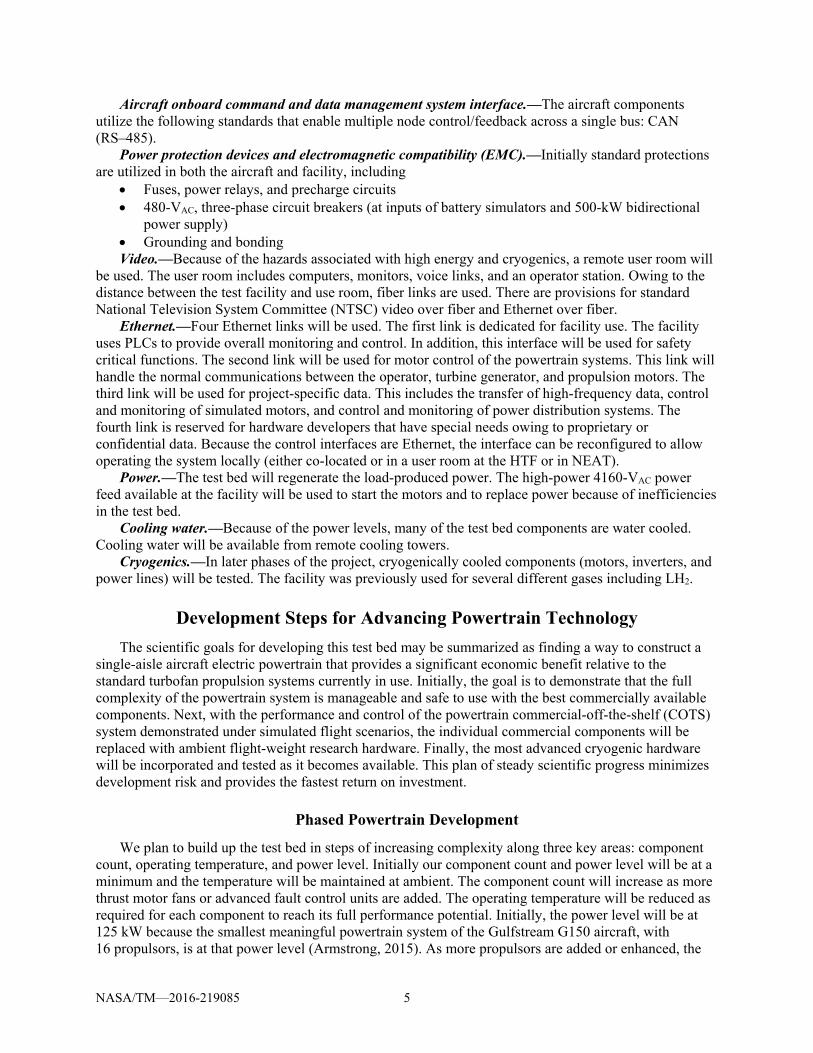
With relatively minor investments, this facility was recently refurbished and is ready for our initial tests of a single-string component of the full-scale powertrain. Figure 2 shows the interior of the facility, with views from opposite ends, and Figure 3 shows the reconfigurable test bed as installed in the facility. Initially, we are using only a portion of the building, but future extensibility is readily available as required.
Figure 1.—Exterior of NASA Electric Aircraft Test bed (NEAT). LH2, liquid hydrogen.
Figure 2.—Interior of NASA Electric Aircraft Test bed (NEAT).

NASA/TM—2016-219085 4
Figure 3.—Interior layout of NASA Electric Aircraft Test bed (NEAT).
It is worth noting that the control room for the test bed is remotely located about ¼ mile from the test
bed for safety reasons. This level of safety, combined with the remote location of this test bed, enables a host of opportunities for unique full-scale powertrain testing under actual flight scenarios involving cryogenic fuel, high-voltage, large wingspan, electromagnetic interference, and high power research hardware.
Facility and Test Bed Interfaces
NEAT will connect to both the building and research hardware with the following interfaces: Power interfaces.—The simulated aircraft direct-current (DC) bus, control, and instrumentation will
be supplied with 4160-VAC/480-VAC three-phase 750-kW facility service (exterior) 220-VAC, 10 percent, one phase (interior) 120-VAC, one phase (interior) Aircraft onboard power interfaces.—The onboard aircraft generators and hybrid battery are
configured as 2-MW generator output that is upgradable to 20 MW Four 100-kW battery simulators Facility regenerative-load-side power interfaces.—The fan load dynamometers are used to simulate
in-flight ducted fans and feedback thrust power to the facility power supply that in turn powers the simulated turbines that drive the generators:
2-MW turbine power upgradable to 20 MW 500-kW bidirectional 600- to 1000-VDC power supply Facility command and data management system (CDMS) interfaces.—Remote control of the
facility and test bed is with Ethernet and a Programmable Logic Controller (PLC).
NASA/TM—2016-219085 5
Aircraft onboard command and data management system interface.—The aircraft components utilize the following standards that enable multiple node control/feedback across a single bus: CAN (RS–485).
Power protection devices and electromagnetic compatibility (EMC).—Initially standard protections are utilized in both the aircraft and facility, including
Fuses, power relays, and precharge circuits 480-VAC, three-phase circuit breakers (at inputs of battery simulators and 500-kW bidirectional
power supply) Grounding and bonding Video.—Because of the hazards associated with high energy and cryogenics, a remote user room will
be used. The user room includes computers, monitors, voice links, and an operator station. Owing to the distance between the test facility and use room, fiber links are used. There are provisions for standard National Television System Committee (NTSC) video over fiber and Ethernet over fiber.
Ethernet.—Four Ethernet links will be used. The first link is dedicated for facility use. The facility uses PLCs to provide overall monitoring and control. In addition, this interface will be used for safety critical functions. The second link will be used for motor control of the powertrain systems. This link will handle the normal communications between the operator, turbine generator, and propulsion motors. The third link will be used for project-specific data. This includes the transfer of high-frequency data, control and monitoring of simulated motors, and control and monitoring of power distribution systems. The fourth link is reserved for hardware developers that have special needs owing to proprietary or confidential data. Because the control interfaces are Ethernet, the interface can be reconfigured to allow operating the system locally (either co-located or in a user room at the HTF or in NEAT).
Power.—The test bed will regenerate the load-produced power. The high-power 4160-VAC power feed available at the facility will be used to start the motors and to replace power because of inefficiencies in the test bed.
Cooling water.—Because of the power levels, many of the test bed components are water cooled. Cooling water will be available from remote cooling towers.
Cryogenics.—In later phases of the project, cryogenically cooled components (motors, inverters, and power lines) will be tested. The facility was previously used for several different gases including LH2.
Development Steps for Advancing Powertrain Technology
The scientific goals for developing this test bed may be summarized as finding a way to construct a single-aisle aircraft electric powertrain that provides a significant economic benefit relative to the standard turbofan propulsion systems currently in use. Initially, the goal is to demonstrate that the full complexity of the powertrain system is manageable and safe to use with the best commercially available components. Next, with the performance and control of the powertrain commercial-off-the-shelf (COTS) system demonstrated under simulated flight scenarios, the individual commercial components will be replaced with ambient flight-weight research hardware. Finally, the most advanced cryogenic hardware will be incorporated and tested as it becomes available. This plan of steady scientific progress minimizes development risk and provides the fastest return on investment.
Phased Powertrain Development
We plan to build up the test bed in steps of increasing complexity along three key areas: component count, operating temperature, and power level. Initially our component count and power level will be at a minimum and the temperature will be maintained at ambient. The component count will increase as more thrust motor fans or advanced fault control units are added. The operating temperature will be reduced as required for each component to reach its full performance potential. Initially, the power level will be at 125 kW because the smallest meaningful powertrain system of the Gulfstream G150 aircraft, with 16 propulsors, is at that power level (Armstrong, 2015). As more propulsors are added or enhanced, the

NASA/TM—2016-219085 6
overall power level may be increased to 24 MW by utilizing the existing 6-MW substation at NEAT with load regeneration.
The high-level development plan depends on project funding, but a representative outlook is provided herein as a guideline. It is divided into four phases:
(1) State-of-the-art testing (fiscal years FY16 to FY17) (2) Full-aircraft-bus ambient research hardware testing (FY18 to FY19) (3) Cryogenically cooled research hardware testing (FY20 to FY21) (4) Integrated-thermal-management research hardware testing (FY21 to FY22)
Phase 1: State-of-the-Art Testing (FY16 to FY17)
During this phase, state-of-the-art (commercially available) power system components will be used to simulate an electrically powered aircraft. This will demonstrate that the facility and test hardware are successfully integrated and will enable the use of more advanced power system components to be used in the next phase.
Phase 2: Ambient Research Hardware Testing (FY18 to FY19)
As new higher performing research hardware is developed under NRA, Small Business Innovation Research (SBIR), and in-house efforts such as the megawatt-class motor/generator and rectifier/inverter, the new technologies will be inserted into the existing test bed. They will be operated at standard temperature and pressure but will provide the high efficiency and less total mass that is required for improved electric aircraft propulsion systems.
Phase 3: Cryogenically Cooled Research Hardware Testing (FY20 to FY21)
Next, the highest payoff technology utilizing cryogenically cooled components will be introduced into the test bed. Initially, this technology will be cooled using liquid hydrogen or liquid natural gas; later, cryocoolers may lift heat to liquid nitrogen.
Phase 4: Powertrain Thermal Management Research Hardware Testing (FY21 to FY22)
Finally, the complete powertrain package will include a system-level thermal management development capable of providing cryogenic temperatures to some or all of the components.
Future Growth
In all phases of testing, thermal management will be important to keep the equipment from over-heating, and in the case of cryogenic components, to keep the subcomponents operating in their super-conducting range, which will vary between 20 and 65 K depending on which superconducting materials are employed. NEAT can support a future thermal management effort that includes cryogenic fuels and/or cryocoolers. In addition, NEAT has room for expansion with low-cost reconfigurations into larger aircraft with higher power systems as the project matures. For example, a full-sized single-aisle aircraft will require about 20 MW for electric propulsion. In addition, opportunities for cost and schedule synergy may exist with cross-center, industry, and academia, such as
Testing a 1-MW cryogenic motor Verifying powertrain performance when commanded with flight control strategies developed at
Armstrong: o A 6-degree-of-freedom hardware-in-the-loop flight simulation will provide accurate dynamic
loads and exercise hardware and energy management across a broad-spectrum of flight profiles. o New and unique flight control algorithms will optimize flight-path energy consumption.

NASA/TM—2016-219085 7
Testing a turboelectric generator at the megawatt level in the acoustic-lined engine test cells that are positioned near the test bed: o Unique full authority digital engine control (FADEC) turbogeneration algorithms could be
developed. o Electromechanical coupling between thermodynamic flow system, mechanical systems, and
electric systems could be investigated. Testing commercial more electric components Supporting future NRA and SBIR efforts Verifying fault-management approaches developed with academic partners Defining and testing Federal Aviation Administration EMI standards Providing an opportunity for different vendor equipment to be integrated into one system
Detailed Concept Development
The test bed shown in Figure 3 is an example of a Gulfstream G150 aircraft converted into a 16-propulsor electrified powertrain vehicle with 2 MW of total thrust power. It was selected as an initial platform geometry that is representative of larger aircraft with a power level that is suitable for imple-mentation with available COTS equipment.
Electrical and Mechanical Concept
The basic concept of NEAT is to support a reconfigurable iron-bird/copper-bird architecture in which the powertrains of a wide range of aircraft at various levels of electrification can be tested under full operational conditions. The entire aircraft powertrain includes the turbines, generators, power electronics, fan motors, ducted fans, fault protection, energy storage, thermal management, and control communication.
A key design feature of the test bed is that all components are reconfigurable and interchangeable. Table II lists the intended range of supported powertrain components. This modular approach enables the reuse of aircraft components as different configurations are required. It also enables the easy replacement of individual components of the test bed as new and improved research hardware becomes available.
TABLE II.—POWERTRAIN COMPONENTS THAT ARE PLANNED TO BE SUPPORTED
Propulsor motors and dynometers Power level .................................................... 125 kW to 1 MW Diameter, m ................................................................0.3 to 0.6 Length, m ....................................................................0.3 to 0.6 Weight, lbm (kg) .............................................. Up to 200 (90.7) Speed, rpm ...................................................................... 20 000
Generator motor and dynometers Power level, MW ........................................................... 1 to 10 Diameter, m ................................................................0.3 to 1.3 Length, m ....................................................................0.3 to 0.6 Weight, lbm (kg) ............................................. Up to 1500 (680) Speed, rpm ...................................................................... 20 000
Thermal management Temperature .................................................... Ambient to 50 K Working fluid ........... Water/ethylene glycol to liquid hydrogen Cooling tube diameter, in. (cm) Main feed .......................................................... Up to 3 (7.6) Secondary feed lines ................................................. 1.5 (3.8)
NASA/TM—2016-219085 8
Test Bed Components
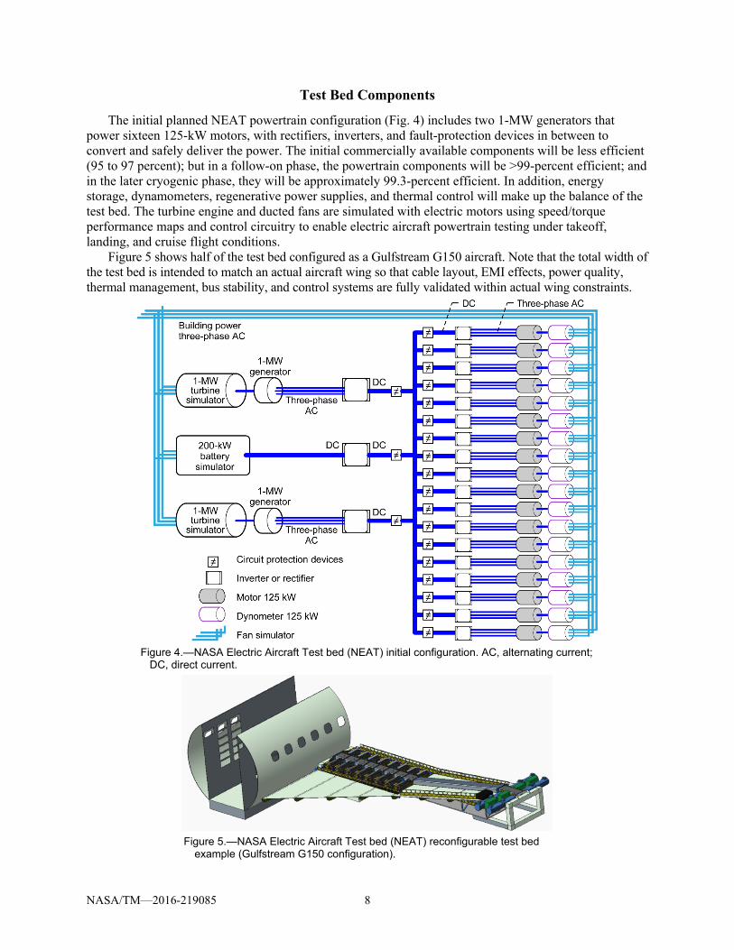
The initial planned NEAT powertrain configuration (Fig. 4) includes two 1-MW generators that power sixteen 125-kW motors, with rectifiers, inverters, and fault-protection devices in between to convert and safely deliver the power. The initial commercially available components will be less efficient (95 to 97 percent); but in a follow-on phase, the powertrain components will be >99-percent efficient; and in the later cryogenic phase, they will be approximately 99.3-percent efficient. In addition, energy storage, dynamometers, regenerative power supplies, and thermal control will make up the balance of the test bed. The turbine engine and ducted fans are simulated with electric motors using speed/torque performance maps and control circuitry to enable electric aircraft powertrain testing under takeoff, landing, and cruise flight conditions.
Figure 5 shows half of the test bed configured as a Gulfstream G150 aircraft. Note that the total width of the test bed is intended to match an actual aircraft wing so that cable layout, EMI effects, power quality, thermal management, bus stability, and control systems are fully validated within actual wing constraints.
Figure 4.—NASA Electric Aircraft Test bed (NEAT) initial configuration. AC, alternating current;
DC, direct current.
Figure 5.—NASA Electric Aircraft Test bed (NEAT) reconfigurable test bed
example (Gulfstream G150 configuration).

NASA/TM—2016-219085 9
Mechanical Configuration
The test bed’s modular construction makes many configurations possible using the same basic building blocks. For example, as larger aircraft are tested, the electric motor dimensions will change. NEAT accommodates this by utilizing interchangeable motor mounts (Fig. 6). NEAT can support electric motors from 125 kW to 10 MW each using this approach, and all components are easily bolted together with mating flanges.
The wing structure also is composed of modular components (Fig. 7), with the 125-kW motor mounts attached in a line. The wing surface and support ribs are bolted together in pieces, making it easy to change the configuration.
Figure 8 shows the complete half-wing bolted assembly with all the standard motor mounts, wing components, cable trays, and circuit protection integrated into a single test bed. This modular construction simplifies manufacturing and assembly while facilitating future geometry changes.
Figure 6.—NASA Electric Aircraft Test bed (NEAT) modular motor mounts (Gulfstream G150 configuration). (a) 125-kW Parker motor/dynamometer. (b) 1-MW pancake motor/dynamometer/generator (0.6 m in diameter by 0.6 m in length). (c) 10-MW pancake motor/generator (1.3 m in diameter by 0.6 m in length). (d) 1-MW wingtip mount.
Figure 7.—Wing modular construction (Gulfstream G150 configuration). (a) Top view. (b) Bottom view.
Figure 8.—Half-wing assembly (Gulfstream G150 configuration). DC, direct current.
NASA/TM—2016-219085 10
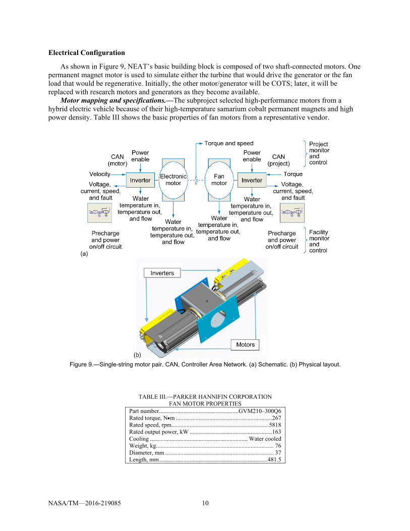
Electrical Configuration
As shown in Figure 9, NEAT’s basic building block is composed of two shaft-connected motors. One permanent magnet motor is used to simulate either the turbine that would drive the generator or the fan load that would be regenerative. Initially, the other motor/generator will be COTS; later, it will be replaced with research motors and generators as they become available.
Motor mapping and specifications.—The subproject selected high-performance motors from a hybrid electric vehicle because of their high-temperature samarium cobalt permanent magnets and high power density. Table III shows the basic properties of fan motors from a representative vendor.
Figure 9.—Single-string motor pair. CAN, Controller Area Network. (a) Schematic. (b) Physical layout.
TABLE III.—PARKER HANNIFIN CORPORATION FAN MOTOR PROPERTIES
Part number .................................................... GVM210–300Q6 Rated torque, Nm ...............................................................267 Rated speed, rpm................................................................ 5818 Rated output power, kW ......................................................163 Cooling ................................................................ Water cooled Weight, kg............................................................................. 76 Diameter, mm ....................................................................... 37 Length, mm ....................................................................... 481.5

NASA/TM—2016-219085 11
Figure 10 shows that the performance curves are similar to an actual CFM34 (General Electric) turbofan engine, with the exception of an order-of-magnitude difference in the torque produced. Initially, NEAT will use both turbine and fan performance maps from in-flight turbofan engines to simulate their physics in the Parker motors.
Motor controller and specifications.—Initially COTS inverters will be used to control both the drive motor and load motor in each motor-motor pair. The hybrid electric ground vehicle market is the most applicable source for drives with a high CAN bus data rate (1 Mb/s), built-in precharge circuits, and small footprint. Table IV shows more details from a representative vendor.
Figure 10.—Speed/torque performance curves. (a) For electric motors.
(b) For aircraft turbofans during takeoff and cruise.
TABLE IV.—RINEHART MOTION CONTROL SYSTEM
MOTOR CONTROLLER SPECIFICATIONS Model ............................................................................. PM100 Controller ... Four-quadrant reversible controller with CAN bus Input voltage, VDC ..................................................... 410 to 800 Power Continuous, kW ................................................................154 Peak, kW ..........................................................................270 Efficiency, percent ................................................................ 97 Cooling ................................................................ Water cooled Weight, kg........................................................................... 15.9 Dimensions, mm .......................................... 574 by 285 by 155

NASA/TM—2016-219085 12
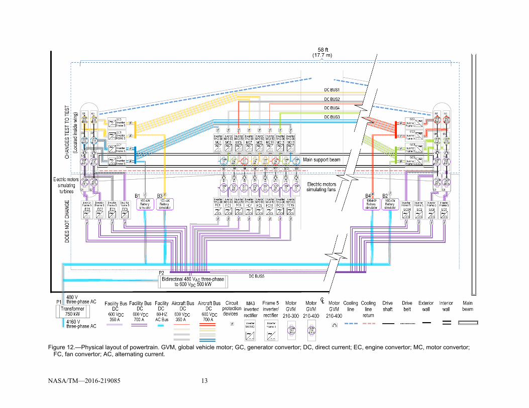
Overall aircraft electrical configuration.—Figure 11 shows all the single-string pairs combined into a single aircraft system with four power distribution DC buses, and Figure 12 shows the physical layout of the overall power cabling when this group of single-string propulsors are combined with the wingtip generators.
Figure 11.—Schematic of 16 single-string propulsors. CAN, Controller Area Network; EMI, electromagnetic interference.
NASA/TM—2016-219085 13
Figure 12.—Physical layout of powertrain. GVM, global vehicle motor; GC, generator convertor; DC, direct current; EC, engine convertor; MC, motor convertor;
FC, fan convertor; AC, alternating current.
NASA/TM—2016-219085 14
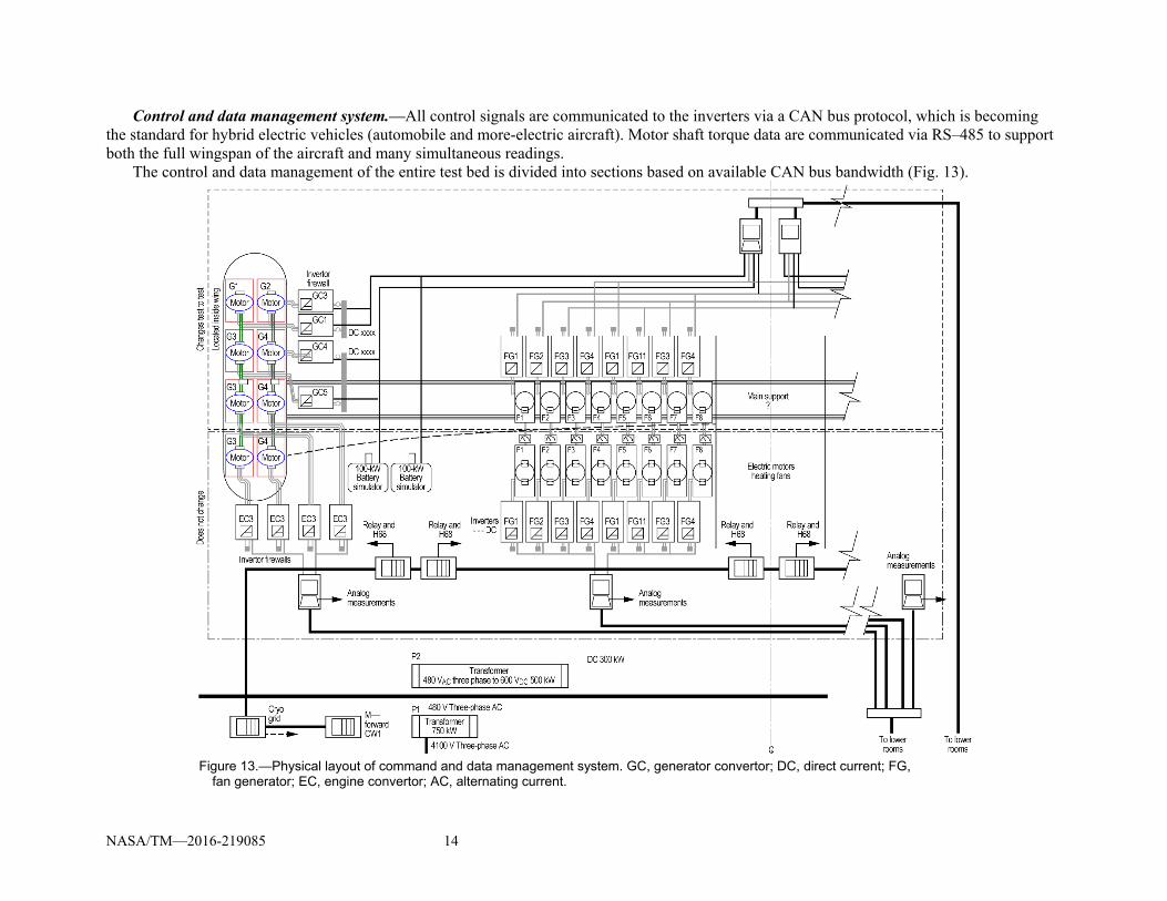
Control and data management system.—All control signals are communicated to the inverters via a CAN bus protocol, which is becoming the standard for hybrid electric vehicles (automobile and more-electric aircraft). Motor shaft torque data are communicated via RS–485 to support both the full wingspan of the aircraft and many simultaneous readings.
The control and data management of the entire test bed is divided into sections based on available CAN bus bandwidth (Fig. 13).
Figure 13.—Physical layout of command and data management system. GC, generator convertor; DC, direct current; FG,
fan generator; EC, engine convertor; AC, alternating current.

NASA/TM—2016-219085 15
System Geometry and Network Topology
It is important to test all the powertrain components within a physical layout that is consistent with the actual aircraft geometry and network topology. The primary reasons for this follow:
Field effects such as EMI and thermal management are sensitive to component proximity. Wave effects such as power-line reflections are sensitive to cabling length. Circuit topology effects such as inverter switching cogging or sparking the motor are sensitive to
inverter and motor connections. System mass is sensitive to the number of power distribution cables and their voltage. Latency effects such as communication rates are sensitive to the number of nodes per topology.
Clearly, it is important to have NEAT look and operate like an aircraft for those reasons and many others. Hence the mechanical reconfigurability, combined with the operational safety and flexibility inherent at the Plum Brook Station, helps to ensure that many of the system complexities are well understood before the powertrain is flight tested.
Test Plan for Fiscal Year 2016
The goal for FY16 is to install and operate a single electric propulsor based on all the same compo-nents that the full-scale test bed will require. The basic steps for achieving this are listed in Table V. This test is important because it will confirm that all the major subsystems required for the full-scale test bed are operational as a system. A more detailed engineering level and implementation plan follows for the single electric propulsor test. See the Appendix for the detailed equipment schematics.
Single-string motor and generator testing.—NEAT’s basic building block is a single-string pair of motors that share a common shaft. This architecture will be used both for turbine-generator and motor-fan mapping. Figure 14 shows the basic components that will be utilized in this test. The pair of power sup-plies can provide up to 180 kW, but the current test will only use approximately 110 kW to stay within facility power current limits. The motor pair will be installed on a machine table for this test, but will later be reused and connected to the larger wing configuration via the standard bolt interfaces. The outdoor chiller will provide the 10 tons of liquid cooling required for the motors and inverters.
Control and data management interface testing.—Initially, while the generalized intelligent motor control (GIMC) is under development, the control and data management system will be verified with an industrial personal computer (PC). This will allow vendor-supplied codes to be used for equipment checkout and monitoring. The torque transducer will use an RS–485 bus with a Universal Serial Bus (USB) converter to provide real-time torque results to the PC, and the inverters will communicate with the PC via a CAN bus. Limited PLC use is anticipated for these initial tests. Once the GIMC is integrated into NEAT, inverter control will be provided via MATLAB/Simulink (The MathWorks, Inc., Natick, MA) and C code downloaded to the GIMC.
Figure 14.—Major test components. (a) Power supply. (b) Motor pair. (c) Outside chiller.
NASA/TM—2016-219085 16
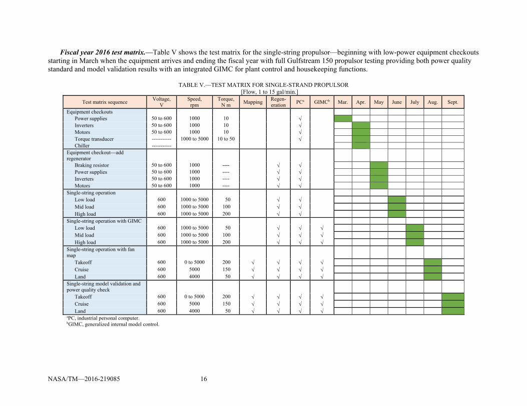
Fiscal year 2016 test matrix.—Table V shows the test matrix for the single-string propulsor—beginning with low-power equipment checkouts starting in March when the equipment arrives and ending the fiscal year with full Gulfstream 150 propulsor testing providing both power quality standard and model validation results with an integrated GIMC for plant control and housekeeping functions.
TABLE V.—TEST MATRIX FOR SINGLE-STRAND PROPULSOR
[Flow, 1 to 15 gal/min.]
Test matrix sequence Voltage,
V Speed,
rpm Torque,
N m Mapping
Regen-eration
PCa GIMCb Mar. Apr. May June July Aug. Sept.
Equipment checkouts Power supplies 50 to 600 1000 10 Inverters 50 to 600 1000 10 Motors 50 to 600 1000 10 Torque transducer ----------- 1000 to 5000 10 to 50 Chiller ----------- Equipment checkout—add regenerator
Braking resistor 50 to 600 1000 ---- Power supplies 50 to 600 1000 ---- Inverters 50 to 600 1000 ---- Motors 50 to 600 1000 ---- Single-string operation Low load 600 1000 to 5000 50 Mid load 600 1000 to 5000 100 High load 600 1000 to 5000 200 Single-string operation with GIMC Low load 600 1000 to 5000 50 Mid load 600 1000 to 5000 100 High load 600 1000 to 5000 200 Single-string operation with fan map
Takeoff 600 0 to 5000 200 Cruise 600 5000 150 Land 600 4000 50 Single-string model validation and power quality check
Takeoff 600 0 to 5000 200 Cruise 600 5000 150 Land 600 4000 50 aPC, industrial personal computer. bGIMC, generalized internal model control.
NASA/TM—2016-219085 17
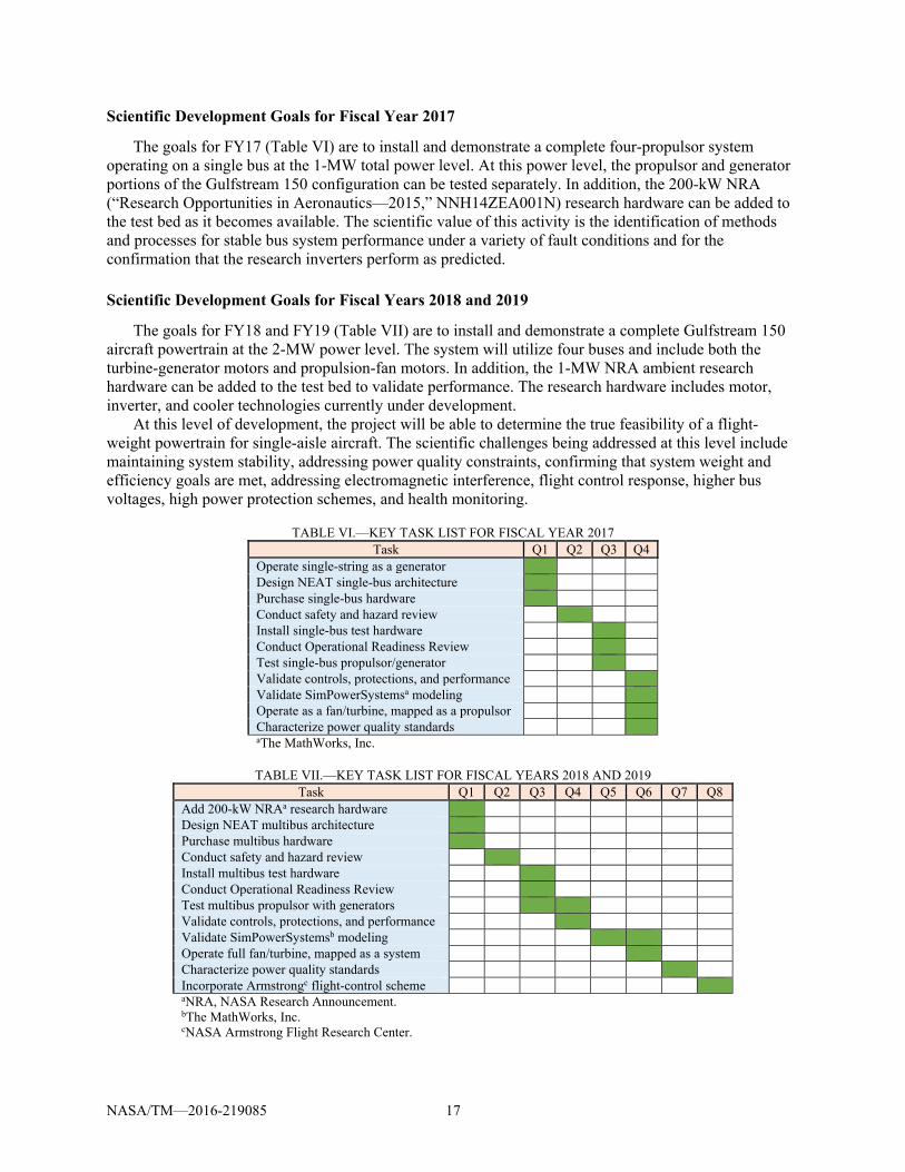
Scientific Development Goals for Fiscal Year 2017
The goals for FY17 (Table VI) are to install and demonstrate a complete four-propulsor system operating on a single bus at the 1-MW total power level. At this power level, the propulsor and generator portions of the Gulfstream 150 configuration can be tested separately. In addition, the 200-kW NRA (“Research Opportunities in Aeronautics—2015,” NNH14ZEA001N) research hardware can be added to the test bed as it becomes available. The scientific value of this activity is the identification of methods and processes for stable bus system performance under a variety of fault conditions and for the confirmation that the research inverters perform as predicted.
Scientific Development Goals for Fiscal Years 2018 and 2019
The goals for FY18 and FY19 (Table VII) are to install and demonstrate a complete Gulfstream 150 aircraft powertrain at the 2-MW power level. The system will utilize four buses and include both the turbine-generator motors and propulsion-fan motors. In addition, the 1-MW NRA ambient research hardware can be added to the test bed to validate performance. The research hardware includes motor, inverter, and cooler technologies currently under development.
At this level of development, the project will be able to determine the true feasibility of a flight-weight powertrain for single-aisle aircraft. The scientific challenges being addressed at this level include maintaining system stability, addressing power quality constraints, confirming that system weight and efficiency goals are met, addressing electromagnetic interference, flight control response, higher bus voltages, high power protection schemes, and health monitoring.
TABLE VI.—KEY TASK LIST FOR FISCAL YEAR 2017
Task Q1 Q2 Q3 Q4 Operate single-string as a generator Design NEAT single-bus architecture Purchase single-bus hardware Conduct safety and hazard review Install single-bus test hardware Conduct Operational Readiness Review Test single-bus propulsor/generator Validate controls, protections, and performance Validate SimPowerSystemsa modeling Operate as a fan/turbine, mapped as a propulsor Characterize power quality standards aThe MathWorks, Inc.
TABLE VII.—KEY TASK LIST FOR FISCAL YEARS 2018 AND 2019
Task Q1 Q2 Q3 Q4 Q5 Q6 Q7 Q8 Add 200-kW NRAa research hardware Design NEAT multibus architecture Purchase multibus hardware Conduct safety and hazard review Install multibus test hardware Conduct Operational Readiness Review Test multibus propulsor with generators Validate controls, protections, and performance Validate SimPowerSystemsb modeling Operate full fan/turbine, mapped as a system Characterize power quality standards Incorporate Armstrongc flight-control scheme aNRA, NASA Research Announcement. bThe MathWorks, Inc. cNASA Armstrong Flight Research Center.
NASA/TM—2016-219085 18
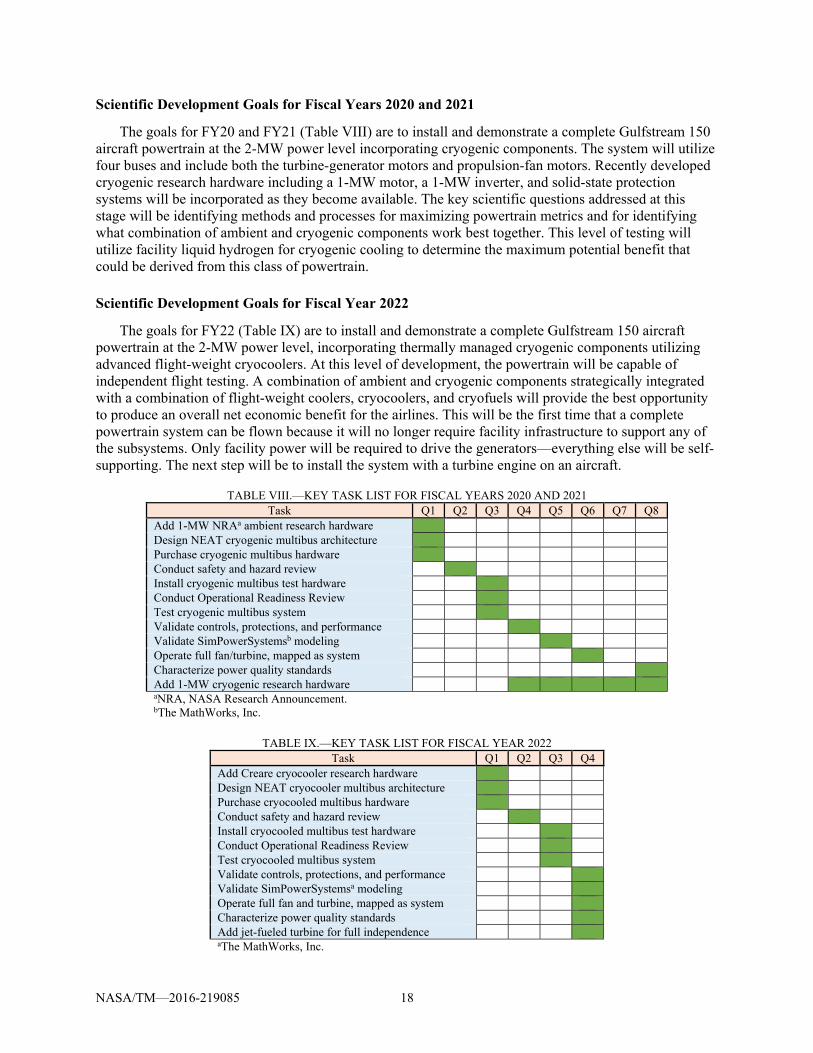
Scientific Development Goals for Fiscal Years 2020 and 2021
The goals for FY20 and FY21 (Table VIII) are to install and demonstrate a complete Gulfstream 150 aircraft powertrain at the 2-MW power level incorporating cryogenic components. The system will utilize four buses and include both the turbine-generator motors and propulsion-fan motors. Recently developed cryogenic research hardware including a 1-MW motor, a 1-MW inverter, and solid-state protection systems will be incorporated as they become available. The key scientific questions addressed at this stage will be identifying methods and processes for maximizing powertrain metrics and for identifying what combination of ambient and cryogenic components work best together. This level of testing will utilize facility liquid hydrogen for cryogenic cooling to determine the maximum potential benefit that could be derived from this class of powertrain.
Scientific Development Goals for Fiscal Year 2022
The goals for FY22 (Table IX) are to install and demonstrate a complete Gulfstream 150 aircraft powertrain at the 2-MW power level, incorporating thermally managed cryogenic components utilizing advanced flight-weight cryocoolers. At this level of development, the powertrain will be capable of independent flight testing. A combination of ambient and cryogenic components strategically integrated with a combination of flight-weight coolers, cryocoolers, and cryofuels will provide the best opportunity to produce an overall net economic benefit for the airlines. This will be the first time that a complete powertrain system can be flown because it will no longer require facility infrastructure to support any of the subsystems. Only facility power will be required to drive the generators—everything else will be self-supporting. The next step will be to install the system with a turbine engine on an aircraft.
TABLE VIII.—KEY TASK LIST FOR FISCAL YEARS 2020 AND 2021 Task Q1 Q2 Q3 Q4 Q5 Q6 Q7 Q8
Add 1-MW NRAa ambient research hardware Design NEAT cryogenic multibus architecture Purchase cryogenic multibus hardware Conduct safety and hazard review Install cryogenic multibus test hardware Conduct Operational Readiness Review Test cryogenic multibus system Validate controls, protections, and performance Validate SimPowerSystemsb modeling Operate full fan/turbine, mapped as system Characterize power quality standards Add 1-MW cryogenic research hardware aNRA, NASA Research Announcement. bThe MathWorks, Inc.
TABLE IX.—KEY TASK LIST FOR FISCAL YEAR 2022
Task Q1 Q2 Q3 Q4 Add Creare cryocooler research hardware Design NEAT cryocooler multibus architecture Purchase cryocooled multibus hardware Conduct safety and hazard review Install cryocooled multibus test hardware Conduct Operational Readiness Review Test cryocooled multibus system Validate controls, protections, and performance Validate SimPowerSystemsa modeling Operate full fan and turbine, mapped as system Characterize power quality standards Add jet-fueled turbine for full independence aThe MathWorks, Inc.

NASA/TM—2016-219085 19
The key scientific questions addressed at this stage will be identifying methods and processes for a self-sustaining powertrain that can fly on an aircraft without institutional support of any of its subsystems. As the thermal management system operates, it will be another load on the system, and the stability of all systems—including power distribution, fault tolerance, thermal, control, and communications—will be observed.
Conclusions
The NASA Electric Aircraft Test bed is a key enabler of flight-weight powertrain development. Its high power, remote location, large footprint, conditioned atmosphere, cryogenic infrastructure, and extensibility make it a unique test bed for full-scale aircraft powertrain development. Not only does it address and fill a role not currently available with existing test facilities, but when used in conjunction with other Government, industrial, and academic facilities, it provides an important next step in the path toward the electrification of future single-aisle aircraft.


NASA/TM—2016-219085 21
Appendix—Fiscal Year 2016 Test Plan for a Single-String Configuration
Figures 15 and 16 provide detailed equipment schematics for the single-string configuration that will be used for the FY16 tests.
Figure 15.—NASA Electric Aircraft Test bed (NEAT) single-string control cabinet. For more information, see Altium (2016). (a) Sheet 1.

NASA/TM—2016-219085 22
Figure 15.—Concluded. (b) Sheet 2.

NASA/TM—2016-219085 23
Figure 16.—NASA Electric Aircraft Test bed (NEAT) single-string inverter/motor. For more information, see Altium (2016). (a) Sheet 1.

NASA/TM—2016-219085 24
Figure 16.—Concluded. (b) Sheet 2.
NASA/TM—2016-219085 25
References
Altium, Limited, 2016: Resources/Documentation. http://techdocs.altium.com/ Accessed May 24, 2016. Armstrong, Michael, 2015: Superconducting Turboelectric Distributed Aircraft Propulsion. Presented at
the Cryogenic Engineering Conference/International Cryogenic Materials Conference, Tucson, AZ. Choi, Benjamin, et al., 2014: Propulsion Electric Grid Simulator (PEGS) for Future Turboelectric
Distributed Propulsion Aircraft. GRC–E–DAA–TN16241. Clarke, Sean, et al., 2014: Enabling Electric Propulsion for Flight—Hybrid Electric Aircraft Research at
AFRC. AFRC–E–DAA–TN15761. Department of Defense, 2015: Department of Defense Interface Standard: Requirements for the Control
of Electromagnetic Interference Characteristics of Subsystems and Equipment. MIL–STD–461G. Jansen, Ralph, et al., 2015: Turboelectric Aircraft Drive Key Performance Parameters and Functional
Requirements. AIAA 2015–3890. RTCA, Inc., 2010: Environmental Conditions and Test Procedures for Airborne Equipment, DOE–160G.
http://www.rtca.org/store_search.asp?keyword=&title=&docnumber=&cat=&committee=SC-135&issuemonth=&issueyear=&dowhat=Search# Accessed May 24, 2016.


