nasa contractor report 187466 evaluation of an … · nasa contractor report 187466 evaluation of...
TRANSCRIPT
NASA Contractor Report 187466
EVALUATION OF AN EXPERT SYSTEM FOR FAULT
DETECTION, ISOLATION, AND RECOVERY IN THE
MANNED MANEUVERING UNIT
John Rushby and Judith Crow
SRI INTERNATIONAL
Menlo Park, California
Contract NAS1-18226
December 1990
National Aeronautics andSpace Administration
Langley Research CenterHampton, Virginia 23665-5225
https://ntrs.nasa.gov/search.jsp?R=19910008300 2019-02-17T01:20:15+00:00Z

Abstract
We explore issues in the specification, verification, and validation of AI-
based software using a prototype Fault Detection, Isolation, and Recov-
ery (FDII_) system for the Manned-Maneuvering Unit (MMU). We use the
MMU FDIR system, which is implemented in CLIPS, as a vehicle for ex-
ploring issues in the semantics of CLIPS-style, rule-based languages, the
verification of properties relating to safety and reliability, and the static and
dynamic analysis of knowledge-based systems. Our analysis reveals errors
and shortcomings in the MMU FDII_ system and raises a number of issues
concerning software engineering in CLIPS.
In the course of this work we came to realize that the MMU FDIR system
does not conform to conventional definitions of AI software, despite the fact
that it was intended and indeed presented as an AI system. We discuss this
apparent disparity and related questions such as the role of AI techniques
in space and aircraft operations and the suitability of rule-based languages
such as CLIPS for critical applications.
..°
111
4 •
P_2CEDiNG p_E BLAr',JK NOT F_L_D

:>°,.-_

Contents
1
2
3
4
Introduction 1
MMU Overview
2.1 Background ............................
2.2 MMU Architecture ........................
2.2.1 Major Components ....................
2.2.2 Architectural Features of the MMU FDIR .......
2.3
4
4
5
5
8
MMU FDIR Implementation .................. 10
Specifications for MMU FDIR 12
3.1 Fault Detection, Isolation, and Recovery ............ 13
3.1.1 Fundamentals of FDIR .................. 13
3.1.2 Potential and Actual FDIR for the MMU ....... 15
3.2 Formalizing Properties of the MMU FDIR System ...... 15
3.2.1 Fault Detection ...................... 16
3.2.2 Fault Isolation and Recovery .............. 20
3.3 Summary of Requirements .................... 21
Semantics for CLIPS-Like Languages
4.1 Semantics for CLIPS .......................
4.2
23
23
4.1.1 A Formal Framework .................. 24
4.1.1.1 Elements of CLIPS .............. 25
4.1.1.2 A Formalization of the Elements of CLIPS 25
4.1.2 Rewriting Interpretations ................ 28
4.1.2.1 Term Rewriting Systems ........... 29
4.1.2.2 A Rewriting Interpretation of CLIPS .... 30
4.1.2.3 Analysis .................... 32
Verifying Properties of CLIPS Programs ............ 34
v
_a_ _©T F_ _:r_
4.3
4.2.1 Invariant and Transition Properties ........... 344.2.2 Termination ........................ 35Summary ............................. 35
5 Static Analysis5.15.25.3
5.4
37Issuesin the Verification of the MMU FDIR .......... 37Experiments with the CLIPS Execution Cycle ......... 39CLIPS and SoftwareEngineering Issues ............ 435.3.1 Pragmatics and the CLIPS Version of the MMU FDIR 445.3.2 Static AnMysis in the CLIPS Environment ...... 455.3.3 Efficiency Considerations ................ 475.3.4 A BASICImplementation of the MMU FDIR ..... 49Summary ............................. 50
6 Dynamic Analysis 526.1 Functional Testing ........................ 53
6.1.1 RevealingSubdomains .................. 536.1.2 Random Generationof Test Data ............ 556.1.3 A Synthesis ........................ 556.1.4 MMU FDIR Evaluation I: Functional Testing Tech-
niques ........................... 556.2 Structural Testing ........................ 61
6.2.1 A Definition of Execution Path for Rule-BasedSoftware 616.2.1.1 ProposalsExtant in the AI Literature .... 62
6.2.1.2 An Alternative Proposal ........... 64
6.2.2 Path Criteria for Rule-Based Software ......... 67
6.2.3 MMU FDIR Evaluation II: Structural Testing Tech-
niques ........................... 67
6.3 Summary ............................. 70
7 Summary and Conclusions 72
7.1 Summary of Errors Found .................... 72
7.2 Conclusions ............................ 74
7.3 Future Work ........................... 78
A Description of Control Electronics Assembly 79
B MMU FDIR Log for Unanticipated Failure Mode 83
vi

C A BASIC Implementation of the MMU FDIR 86C.1 BASICLog for Unanticipated Failure Mode ........... 89
Bibliography 90
vii
List of Figures
2.1 MMU FDIR System Components and Information Flow . . . 6
2.2 MMU Thruster Triad Arrangement ............... 7
3.1 State Diagram for MMU FDIR ................. 16
3.2 Input/Output State and Command SignMs for CEA ..... 17
6.1 Execution Flow Graph for Kiper t_ule Set ........... 66
6.2 Revised Execution Flow Graph for Kiper Rule Set ...... 67
6.3 Execution Flow Graph for CEA-A Failure Recovery ...... 69
viii
List of Tables
6.1 MMU FDIR Problem Partitions ................ 57
6.2 Revealing Subdomains for the MMU .............. 59
6.3 Results of MMU FDIR Subdomain Testing .......... 60
ix

Chapter 1
Introduction
In previous work undertaken for NASA we examined the issues of qual-
ity assurance for AI-based software and proposed methods for specifying,
verifying, and validating rule-based AI systems [34,35]. In this report we
evaluate some of our proposals in a concrete setting and discuss practical
issues concerning software engineering for rule-based systems.
The vehicle for our experiments is a prototype system for Fault Detec-
tion, Isolation, and Recovery (FDIR) [24] in the Manned Maneuvering Unit
(MMU) [27]. There are significant advantages and disadvantages to this
particular choice of test vehicle. Principal among the advantages is the fact
that both NASA and the authors of the MMU FDIR system were willing to
make the system available for our potentially critical evaluation and were
most helpful in securing source code and additional documentation. We are
particularly grateful to the MMU FDIR authors for giving us this opportu-
nity. A further advantage, from our point of view, is that the MMU FDIR
system had been intended only as a demonstration prototype and had there-
fore not been subject to exhaustive prior testing or examination. This gave
us the opportunity to work with a system potentially containing residual
faults--fertile ground for exploring our ideas.
Principal among the disadvantages of this choice of test vehicle is the fact
that the MMU FDIR system is not AI software in any meaningful sense: it
performs an entirely procedural set of tests and actions. Although this claim
is intuitively obvious, it is somewhat difficult to substantiate; there are no
characteristics of AI software which are not also applicable to some degree
to conventional software. For example, Buchanan and Smith [4, pp. 23-24]
cite five "desiderata" for expert systems which, taken together, characterize

2 Chapter 1. Introduction
a "distinct class of programs." While the five desiderata reproduced below
provide useful guidelines, they are hardly definitive characteristics. 1 An
expert system is a program that
1. reasons with domain-specific knowledge that is symbolic as well as
mathematicM;
2. uses domain-specific methods that are heuristic (plausible) as well as
Mgorithmic - (certain);
3. performs as well as specialists in its problem area;
4. makes understandable both what it knows and the reasons for its an-
swers;
5. retMns flexibility.
Although a definitive characterization is elusive, it is possible to identify
certain hallmarks of expert systems including, as suggested above, the fun-
damental role of the knowledge base. This defines a typically intractable
solution space, and the second hallmark of expert systems is the use of
heuristic search as the problem solving paradigm for exploring that space.
Despite the fact that the MMU FDIR system arguably fails to meet virtu-
ally all of the preceding desiderata, our claim that the MMU FDIP_ system
is not AI Software rests primarily on the fact that it fails to satisfy the sec-
ond of the two hallmarks; the MMU FDIR, system encodes a fundamentally
Mgorithmic process and does not employ heuristic search.
Nevertheless, the MMU FDII_ system is programmed in CLIPS [2,17], a
forward-chaining rule-based language of the kind generally associated with
the term "expert system," and for this reason alone, many would consider
the MMU FDIR, an expert system; this is certainly how it was represented
to us. Therefore our discovery that the MMU FDIR system is in fact "just
a program" is potentially interesting. Most of the examples in the text book
on programming expert systems in CLIPS [18] have a similar character and
it is entirely possible that other "expert systems" extant or under consid-
eration in NASA may share similar properties. The lack of a significant
AI component in the MMU FDIR system has focused our evaluation more
1We do not mean to suggest that Buchanan and Smith's presentation is impoverished; itis surely fruitless to search for definitive characteristics in the continuum from conventionalto AI programming. Note that characteristics 1 and 2 above define AI programs generally.

closelyon issuesof programming and softwareengineeringin rule-basedno-tations suchas CLIPS.
The organization of this report is as follows. Chapter 2 provides anoverviewof the MMU and the MMU FDIR strategy, including a descriptionof the functional design of the MMU and a summary of the MMU FDIRimplementation. Chapter 3 considersgenerMissuesof FDIR in the contextof constructing formal specificationsfor the MMU FDII_. Chapter 4 devel-ops a formM semanticsfor CLIPS-style rule-basednotations and exploresverification of declarative properties of CLIPS programs. The problemsweencounter with verification for CLIPS-style programs raise basic softwareengineering issues;Chapter 5 summarizesthe pragmatics of CLIPS and itsimpact on the MMU FDIR implementation. We shift the focus from lan-guageto testing issuesin Chapter 6, which presentsfunctionM and structuraltesting techniquesfor rule-basedlanguagesin generaland the MMU FDIRin particular. The final chapter summarizesand explores the implicationsof our work and outlines issuesof interest for future research.
Chapter 2
MMU Overview
The discussion in this chapter focuses on the architecture of the NASA
Manned Maneuvering Unit (MMU); the strategies of its Fault Detection,
Isolation, and Recovery (FDIR) 1 system; and the assumptions and main
characteristics of its implementation in the C Language Production System
(CLIPS). We have relied on two major sources of information in preparing
this description of the MMU: the final report of the MMU FDII_ automation
task [24] and the MMU Systems Data Book [27].
2.1 Background
The MMU Systems Data Book [27] describes the MMU as "a zero-gravity
maneuvering unit designed for astronaut extravehicular activity (EVA)
which is entirely self-supporting; i.e., it contains its own electrical power,
propulsion, controls and displays." And in further detail:
"The MMU is a propulsive backpack operated by separate hand
controls located on adjustable arms which extend forward from
the pack. The pilot's translational and rotational maneuver-
ing commands are input via the hand controllers and processed
by the control electronics which operate the thruster valves of
the gase0us-nitrogen (GN2) propulsion system. The MMU has
1The MMU FDIR code documentation ( [24, p. 1]) defines the acronym "FDIR" as FaultDiagnosis, Isolation, and Reconfiguration. For reasons discussed in this and subsequentchapters, we feel the phrase "Fault Detection, Isolation, and Recovery" more accuratelyreflects common usage.
2.2. MMU Architecture
twenty-four thrusters providing six-degree-of-freedom maneuver-
ability with either manual or automatic attitude hold. Two com-
pletely redundant electronic and propulsion systems provide full
backup capability for single failures; in the case of a second or
backup mode failure, the MMU pilot would have to call for or-
biter rescue."
The MMU is fully specified by complete formal requirements statements;
detailed schematics for subsystems, hardware, and interfaces; and precise op-
erational, maintenance, and performance profiles in the MMU Systems Data
Book [27]. However, the MMU modeled in the MMU FDIR system and de-
scribed in this chapter is a substantially simplified version of the real MMU.
It is essential to keep both this simplification and the primary objective of the
MMU FDIR automation task in mind when reading the next three sections.
The goal of the MMU FDIR project was to investigate the use of available
AI technology to automate the FDIR function of the MMU [24, p. 1] and
was motivated by the fact that the real MMU incurs significant operational
limitations because FDIR is handled manually by the pilot. Although the
MMU modeled in the MMU FDIR system can be viewed as a highly simpli-
fied version of the real MMU, the authors of the MMU FDIR project state
that the automated MMU FDII_ project represents a serious attempt to use
current AI technology in an ultimately critical application and we analyze
the MMU FDIR system accordingly [24, pp. 1-2,8-9].
2.2 MMU Architecture
The discussion in the remainder of this chapter is based on the model dia-
grammed in Figure 2.1.
2.2.1 Major Components
The MMU modeled in the MMU FDIR is a symmetric, three component
system consisting of a Control Electronics Assembly (C_,A) and a GN2
tank assembly/thruster unit for each of two sides, A and B, and a sepa-
rate GYRO unit. Each of the two CEAS, CEA-A and CEA-B, receive hand
control signals for either translational--x, y, z--or rotational--pitch, yaw,
roll--acceleration, or GYRO input commanded by the Automatic Attitude
Hold (AAH). In response to a Translational Hand Control (THC), Rotational
Hand Control (RHc) or GYRO input, the appropriate CEA issues commands

Chapter 2. MMU Overview
I
CEA_A power
m
,_E,
A
-- -B pwr status
--A pwr
m
CEAB power
AAH SELECT
TIIANS ClV[DS
ROTATE CMDS
A xfeed actuator
B xfeed
B xfeed actuator
)ressure
[A iso-valve
A thrusters
iso-v'alve
I B tank_ressureCEABisolate
Figure 2.1: MMU FDI1% System Components and Information Flow

2.2. MMU Architecture 7
to the corresponding Valve Drive Amplifier (VDA A or VDA B), which ulti-
mately fires the associated thrusters. Each of sides A and B is assigned twelve
thrusters arranged in four cluster triads as shown in Figure 2.2. The nota-
tion in Figure 2.2 has the following interpretation: the arrowheads represent
thrusters and have three-part labels indicating the intended direction when
the thruster is fired (one of Forward, Backward, Right, Left, Up, Down--
F,B,I_,L,U,D, respectively), the cluster number (1-4), and side (A or S). For
example, "F-l-B" indicates the thruster for forward acceleration located in
the first cluster on side B.
D.
L-l-A=
B-1-A j
B-3-B U-3-B
D-1-B
L-1-B_ F-1-B
= I:1,-2-B
U-3-A
B-4-AU-4-A
D-2-AF-2-A
¢_p R-2-A
F-4-B
_ R-4-B
- R_4-A
Figure 2.2: MMU Thruster Triad Arrangement
Each CEA has both a primary and a backup operating mode. In primary
mode, both CEAs operate and share control of the thrusters. In backup
mode, only one CEA operates and it controls all operative thrusters. If a
primary mode failure is detected in one of the CEAs, the MMU is reconfigured
to operate with one of the CEAS in backup mode.
There are interesting asymmetries in the functional assignments to sides
A and S for CEA and GYRO activity. In normal operation mode, CEA func-
tions for positive pitch, yaw, and roll are assigned to side A, negative pitch,
yaw, roll to side B. Normal gyro-mode assignments are the converse: pos-
itive pitch, yaw, roll are handled on side B, negative pitch, yaw, roll on
8 Chapter 2. MMU Overview
side A. The converse relation also holds between the assignments for CP,A
and GYRO in backup modes. As an example, consider the primary mode
CEA and GYRO thruster configurations for an acceleration in the positive
direction about the pitch axis.
• CEA Configuration: side A thrusters: B1 and F3side B thrusters: none
• GYRO Configuration: side A thrusters: noneside B thrusters: F1 and B3
In addition, there are biases in thruster assignments; acceleration in the
direction of the x axis uses four thrusters per side, whereas accelerations
along all other axes use only two thrusters per side. Finally, for the x, y,
z axes, the positive orientations are front, right, and down, the negative
orientations back, left, and up.
The most significant component-lev.el differences between the MMU
modeled in the MMU FDIP_ system and the real MMU are the following
(cf. Appendix A).
o
.
.
The modeled MMU has a single separate gyro component, whereas
the real MMU has two CEA-internal gyros.
The MMU FDII_ system models the AAH, THC, RHC, and GYRO, which
are detailed components in the real MMU, as simple inputs to the CEA,
i.e., simple inputs which do not reflect the actual internal structure of
these components.
The MMU isolation valves for sides A and B are not modeled in the
MMU FDIR.
4. The MMU FDIR assumes status information is shared between CEA-A
and CEA-B, which is apparently not the case in the real MMU.
2.2.2 Architectural Features of the MMU FDIR
The MMU modeled in the MMU FDII% is assumed to experience at most
a single failure in a single component at any given time. No behavioral
properties or internal structure are modeled for the AAH, THC, RHC, and
GYRO: they are treated as indivisible entities, modeled only by their inputs
to the tEA. Consequently, CEA and Tank/Thruster failures are effectively

2.2. MMU Architecture 9
the only malfunctions that can be detected by the FDII_ system. For exam-
ple, although a failure in normal gyro mode is reported as an AAH failure,
it is detected and recorded internally as a CEA failure. There is a further
architectural simplification relevant to FDIR. In the MMU, there is a pre-
sumably complex relationship between CP.A input and VDA commands2; the
CEA integrates multiple inputs and generates appropriate control signals for
the VDA as specified by the control laws. 3 In the MMU FDIR this com-
plex relationship is reduced to a simple function of a single input; at any
given time there is at most one input from one ofTHC, ltHC, or GYRO which
uniquely determines the outputs sent to the VDA. Furthermore, both inputs
and outputs are simple on/off values.
As mentioned previously, if the MMU FDIR system detects a primary
mode failure in one of the CEAs, the MMU is reconfigured to operate with
at most one CEA in backup mode. The choice of which CEA to use in backup
mode is determined as follows.
1. If both CEAs are OK in backup mode, use the one which did not exhibit
the original failure in primary mode. 4
2. If only one C_,A is OK in backup mode, use it.
3. If neither CEA is OK in backup mode, call for help.
Fault detection in primary mode and testing in backup mode is accom-
plished by comparing a single CEA input and its corresponding output to the
VDA. Any disparity between the observed and expected output to the VDA
is taken to indicate failure of the CEA side/mode concerned; agreement in-
dicates the given component is functioning correctly. The expected outputs
to the VDA for a given input to the C_,A are found by a rule-based encoding
of table lookup. 5As noted in item 4 in the list of differences between the MMU FDIR
and the real MMU, the authors of the MMU FDIR apparently modeled
2The tEA translates input commands into VDA control signals which specify whichthrusters to fire. We refer to the control signals sent from the CEA to the VDA as VDAcommands.
3Cf. Chapter 3, Section 3.2.1 and Appendix A.4The possibility that both CEAs could be OK in backup mode following a primary
mode failure seems to suggest a 2-fail-operational, fail-safe capability, rather than theadvertised 1-fail-operational, fail safe capability. This discrepancy is not explained in theMMU FDIR documentation.
5Cf. Section 2.3 of this chapter.

10 Chapter 2. MMU Overview
instrumentation unavailable in the real MMU to allow sides A and B to share
their respective statuses in order to reduce the time required for diagnosis
and recovery. Thus on primary mode failure, the pilot of the real MMU first
isolates a side chosen at random, whereas the shared information modeled in
the MMU FDIR allows the failing side to be located and isolated first. Since
both sides are tested in backup, it's not clear the innovation in the MMU
FDIR system actually reduces the time interval between fault detection and
fault recovery or reduces risk to the pilot.
We take up the issue of FDIR again in Chapter 3, where we consider
issues involved in formal specifications for the MMU FDII_. First, however,
we conclude our introduction to the MMU FDIR system with an overview
of the MMU FDIR implementation.
2.3 MMU FDIR Implementation
The MMU FDIt_ CLIPS code consists of 104 rules with the following func-tional distribution.
• Encoding correct thruster configurations for sides A, B, and GYRO in
primary and backup modes: 73 rules.
• Failure recovery for CEA-A and CEA-B: 14 rules.
• Tank/thruster tests: 7 rules.
• Printing and demonstration: 10 rules.
This breakdown accurately reflects the inefficiencies of encoding basi-
cally tabular information, namely the association of correct VDA commands
with given CEA inputs, in separate, highly redundant productions. The re-
dundancy is a result of the fact that modulo the above-mentioned mapping
between CEA input and VDA commands, there are only four distinct "states"
encoded in the 72 rules which test CEA input against VDA commands: pri-
mary mode CEA, primary mode GYRO, backup mode CEA, and backup mode
GYRO. The notion of state is particularly relevant because the MMU FDIR
is basically a procedural program, i.e., a program which executes an explicit
procedure qua case-by-case analysis. This view of the MMU implementation
is confirmed by the explicit encoding of state; there are approximately ten
"state variables," at least two of which are used in every FDIt_ rule to en-
code the state of the FDIR process. To anticipate the discussion in Chapter

2.3. MMU FDIR Implementation 11
3, these states correspond roughly to the constraints implied by the combi-
nation of node and incoming edge labels in Figure 3.1 on page 16 of Section
3.2. For example, consider the state corresponding to node 4 in Figure 3.1;
we can characterize this state as the second stage of backup testing where
side S has failed in both primary and backup mode and side A backup is to
be tested. The MMU FDII_ encoding of this state uses the following statevariables and values. 6
• backup mode test: (SIDE A ON), (SIDE B OFF)
• side B failure: (FAILURE CEA-B)
• test side A backup: (NOT (FAILURE CEA-A))
It is frequently asserted that knowledge bases are fundamentally declar-
ative and therefore it is possible to understand a rule-base without reference
to its associated inference engine. For reasons discussed in Chapter 5, we
take issue with this claim. Thus we assert that it is impossible to understand
the MMU FDII_ code without comprehending the flow of control implicit in
the FDIR system and by implication, without understanding the interaction
of code-internal and code-external factors. We have presented an overview
of the MMU FDII_ implementation here. We consider code-external fac-
tors such as the CLIPS execution cycle, as well as code-internal factors, i.e.,
the explicit encoding of state---control flows from one state to another as a
function of the assertion/retraction of state variable settings--and the static
organization of the code in Chapter 5.
This completes our overview of the MMU FDIP_ model, strategy, and
implementation. In the next chapter we develop more formal specifications
for the functionality we have outlined here.
6For each item we indicate the state attribute characterized and the MMU FDIR
encoding.
Chapter 3
Specifications for MMUFDIR
In this chapter we consider the construction of formal(ized) specifications
for the MMU FDIR system. One of the original motivations for this study
was to examine our notions of minimum competency requirements [34] in
a practical and concrete setting. Minimum competency requirements were
motivated by the desire to identify some facet of the performance of AI
software that could be subject to objective specification and evaluation.
However, since the MMU FDIR system has a rather minimal declarative
basis, the application of minimum competency requirements is somewhat
questionable; the MMU FDII% system is an entirely procedural system whose
requirements can be specified in full and precise detail. As a result, our
investigations took a somewhat unexpected turn; the MMU FDII_ system led
us to identify a requirement applicable to a certain class of AI software which
we had previously overlooked, namely the requirement to perform certain
prescribed procedures--e.g., "first switch off this component, then test that
function; if the reading is OK, wait for 5 seconds and then .... " Accordingly,
in this chapter we attempt to interpret the requirements for the MMU FDIR
system in terms of safety properties, including the subclass of transitional
properties which at least partially captures procedural requirements, and
the notion of model inversion [35]. As a preliminary, we briefly characterize
the basic concepts of FDIt_.
12

3.1. Fault Detection, Isolation,and Recovery
3.1 Fault Detection, Isolation, and Recovery
13
Fault Detection, Isolation, and Recovery (FDIR) is an important aspect of
any system that must continue to provide service despite faults and fail-
ures in its components. Fault detection is the process of recognizing that
something has gone wrong; fault isolation is the process of determining the
components of the device that have failed; fault recovery is the process of
determining the steps to correct the fault, or to work around it. In this
section we first discuss general FDII_ issues and then consider the particular
FDIR strategies implemented in the MMU FDIR system.
3.1.1 Fundamentals of FDIR
Fault detection usually requires active monitoring of sensors and comparison
between observed and expected (or desired) values. In systems that include
closed-loop control, the inputs and outputs of the control system need to
be monitored along with sensor values. The correct selection of sensor loca-
tions and monitored values is critical to timely fault detection; for example,
a propellant leak may produce an unwanted acceleration which should be
countered by firing opposing thrusters under the direction of the automatic
attitude-hold (AAH) control system. A fault-detection system that merely
monitors the correct functioning of the AAH control system will not detect
this problem; comparison between actual and expected drops in propellant
tank pressure is required. The mMn opportunities for AI-based approaches
to fault detection seem to be the application of qualitative models to sensor
validation and the prediction of expected behavior [5, 36, 37].
Fault isolation can be considered a restricted case of the problem of fault
diagnosis; for fault isolation it is usually necessary to obtain only a fairly
gross understanding of the nature and source of the problem--it does not
matter whether it is a fan blade or a compressor blade that has sheared if
the engine must be shut down in either case. Fault diagnosis has been a
fertile area for AI applications, starting with experiential associations be-
tween symptoms and faults (so called "expert-systems"), through diagnosis
based on perturbing models of correct behavior, to the more recent work
that combines this earlier work with explicit fault models. Hamscher and
Davis provide a good survey of these topics [11]. Fault isolation in space-
craft differs somewhat from the diagnosis of faults in electrical circuits that
provide the staple of much AI literature in that the machine cannot be taken
out of service while the fault is diagnosed, and control inputs necessary to

14 Cfiapter 3. Specitications for MMU FDIR
counter the effects of the fault may hamper diagnosis as in the example in the
previous paragraph. Abbott [I] refers to this as the problem of "operative
diagnosis ."
Fault recovery is essentially a planning problem [13]; given the location
of the problem (as determined by fault isolation) and the design or possible
configurations of the system, find a configuration that will provide accept-
able functionality. Recovery actions are often preplanned and tested for
anticipated faults, e.g., if a primary subsystem fails, switch to its backup,
but may require considerable inventiveness for major unanticipated faults
(cf. Apollo 13).
Fault isolation in spacecraft systems may often be integrated with re-
covery; for example, the redundancy of mechanism that is necessary for
recovery may also support fault isolation by allowing selected subsystems
to be switched off (with their backups providing the necessary continued
service) in order to determine whether they are responsible for the observed
problems. Fault isolation and recovery in such systems may then have a
strongly procedural element as suggested in the previously cited example:
"first switch off this component, then test that function; if the reading is
OK, wait for 5 seconds and then..." Specialized Al-based systems, such as
SRI's Procedural Reasoning System (PRS) [14-16], have been constructed
to support precisely this type of activity.
We can readily identify reasonable minimum competency properties for
FDIR systems.
Requirements Statement 3.1
1. Faults in a certain class shall not go undetected;
2. spurious faults shall not be detected; 1
3. recovery shall leave the system in an operational--or at least safe--
configuration;
4. at no time should the process of FDIR itself cause the system to enter
unsafe states.
The first and third of these are liveness properties, the second and fourth
are safety properties. Sliced in another dimension, the first two of these
1Obviously, there is the usual tension between minimizing errors of comission and ofomission in satisfying this and the previous requirement simultaneously.

3.2. Formalizing Properties of the MMU FDIR System 15
requirements apply most directly to fault detection, the third and fourth to
fault isolation and recovery.
3.1.2 Potential and Actual FDIR for the MMU
The MMU contains considerable redundancy and would appear to offer ex-
cellent opportunities for automated FDII_. FDII_ is currently performed
manually by the pilot, which imposes certain operational limitations. 2 Un-
fortunately, the failure modes and effects analysis for the MMU is absent
from the documentation available to us [27]. Nevertheless, it seems obvious
that a system of the complexity of the MMU would have a significant number
of possible malfunctions. The MMU FDIR, system prototype reduces this
potentially large number of failures to two major component failures: gross
CEA malfunction and tank/thruster malfunction. In the remainder of this
chapter we focus exclusively on the FDIR for CEA malfunction for the fol-
lowing reasons. First, the FDIR for tank/thruster failure is rudimentary and
only partially implemented; failure is detected by a simple comparison be-
tween expected and measured propellant usage. Second, the tank/thruster
FDIR partition is a very small part of the MMU FDIR system; as noted
previously, out of a total of 104 rules, only 7 implement the tank/thruster
FDIR component and of these, only 5 rules actually perform FDIR, analysis.
As currently implemented, there is not enough to the tank/thruster FDIR
partition to support meaningful application of the techniques we propose.
Hereafter, references to the MMU FDIR system should be interpreted as
references to MMU FDIR procedures for CEA malfunction.
In the following section we take up the real work of this chapter, which
is to provide specifications for the MMU FDII_ system. The state diagram
in Figure 3.1 is intended as a useful guide to the more detailed discussions
of MMU FDIR strategy.
3.2 Formalizing Properties of the MMU FDIR
System
We divide this discussion into two parts, one each for fault detection and
for fault isolation and recovery. A third and final section summarizes and
enumerates a complete requirements specification for the MMU FDIR,.
2See [10] for an interesting discussion of some of the differences in design, redundancy,
and rescue mechanisms between the NASA MMU and its Russian counterpart.
16 Chapter 3. Specifications for MMU FDIR
(_ Test A Primary
good_ __ bad
Test B Primary /,(-_)x, x
• "® A
HELP! Use A Use B Use A HELP! Use B Use A Use B
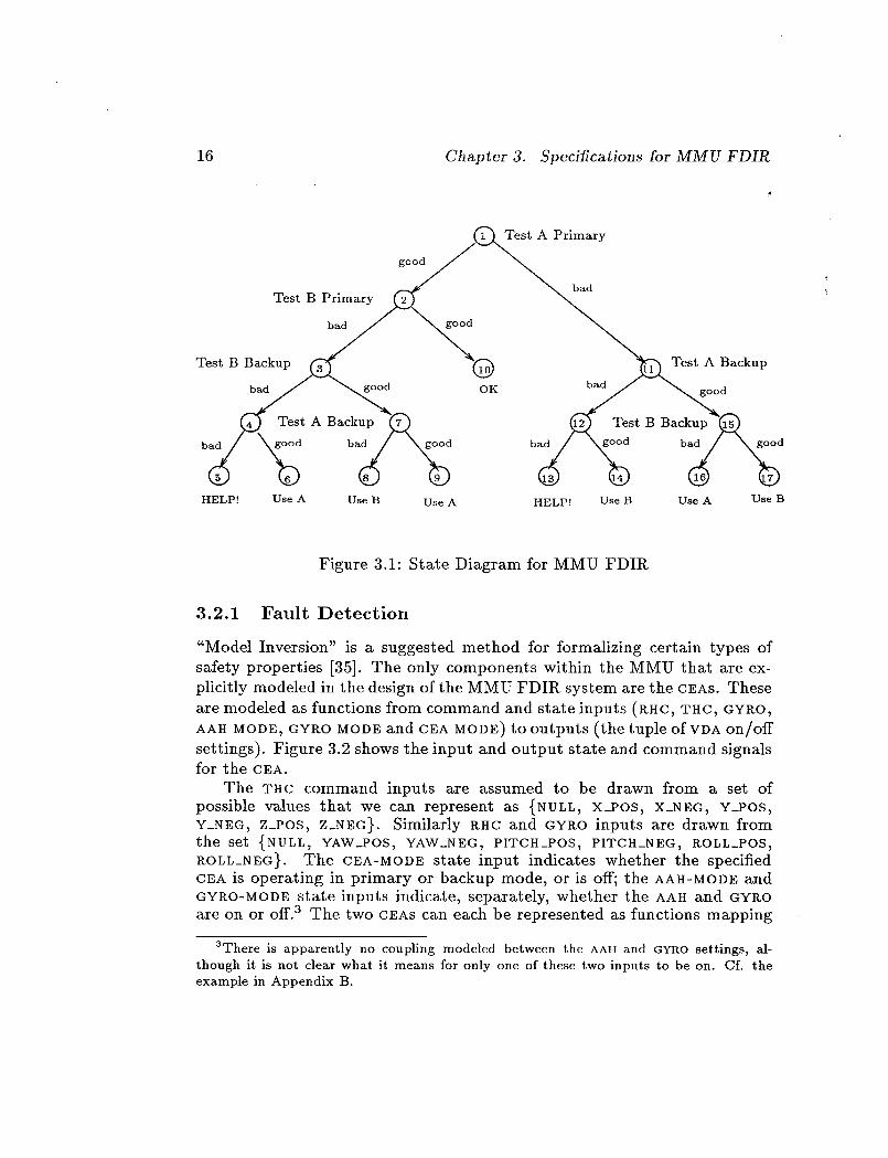
Figure 3.1: State Diagram for MMU FDIR
3.2.1 Fault Detection
"Model Inversion" is a suggested method for formalizing certain types of
safety properties [35]. The only components within the MMU that are ex-
plicitly modeled in the design of the MMU FDIR system are the CEAS. These
are modeled as functions from command and state inputs (RHC, THC, GYRO,
AAH MODE, GYR.O MODE and CEA MODE) to outputs (the tuple of VDA on/off
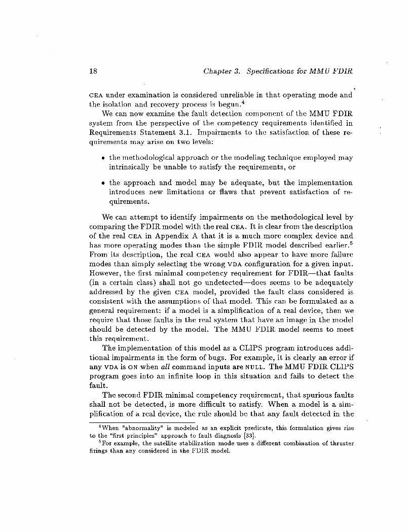
settings). Figure 3.2 shows the input and output state and command signalsfor the CEA.
The THC command inputs are assumed to be drawn from a set ofpossible values that we can represent as {NULL, X_POS, X_NEG, Y_POS,
Y_NEG, Z_POS, Z_NEG}. Similarly RHC and GYRO inputs are drawn fromthe set {NULL, YAW_POS, YAW_NEG, PITCH_POS, PITCH_NEG, ROLL_POS,
ROLL_NEG}. The CEA-MODE state input indicates whether the specifiedCEA is operating in primary or backup mode, or is off; the AAH-MODE and
GYRO-MODE state inputs indicate, separately, whether the AAH and GYROare on or off. 3 The two CEAs can each be represented as functions mapping
3There is apparently no coupling modeled between the AAH and GYRO settings, al-
though it is not clear what it means for only one of these two inputs to be on. Cf. the
example in Appendix B.

3.2. Formalizing Properties of the MMU FDIR System
CEAMODE
17
THC
RHC
GYRO
CEA
TAAH GYROMODE MODE
VDA INPUTS
Figure 3.2: Input/Output State and Command Signals for CEA
the six-tuple of inputs to a VDA configuration:
CEA : THC × RHC × GYRO × CEA-MODE × AAH-MODE × GYR.O-MODE _ VDA-CONFIG.
The actual functions can be specified by an explicit table of input/output
associations (given in tables 2.1.1.3-1 through 8 of [27]). Thus, for example,
for CEA A,
CEA(N LL,H CH_POS,N LL, PR,MARV,orr, oF ) = {B1,r3},where {B1, F3} means that thrusters B1 and F3 are on and all other thrusters
are off. The fault detection component of the MMU FDIR. system can be
said to invert a model that comprises the two CEAS viewed as functions
from inputs to outputs as described above, combined with hypotheses about
whether or not their behavior is "abnormal" in one or more operating modes.
If a CEA is not abnormal in its current operating mode, then the outputs
sent to the VDA should equal those calculated by the functions of the model;
if a CEA is abnormal, then the actual and predicted outputs should differ.
The diagnostic procedure, therefore, is to compare actual with predicted
outputs to the VDA in the operating mode concerned. If these disagree, the
18 Chapter 3. Specifications for MMU FDIR
CEA under examination is considered unreliable in that operating mode and
the isolation and recovery process is begun. 4
We can now examine the fault detection component of the MMU FDII_
system from the perspective of the competency requirements identified in
l_equirements Statement 3.1. Impairments to the satisfaction of these re-
quirements may arise on two levels:
• the methodological approach or the modeling technique employed may
intrinsically be unable to satisfy the requirements, or
• the approach and model may be adequate, but the implementation
introduces new limitations or flaws that prevent satisfaction of re-
quirements.
We can attempt to identify impairments on the methodological level by
comparing the FDIR model with the real CP,A. It is clear from the description
of the real CEA in Appendix A that it is a much more complex device and
has more operating modes than the simple FDIR model described earlier. 5
From its description, the real CEA would also appear to have more failure
modes than simply selecting the wrong VDA configuration for a given input.
However, the first minimal competency requirement for FDIR--that faults
(in a certain class) shall not go undetected--does seems to be adequately
addressed by the given CEA model, provided the fault class considered is
consistent with the assumptions of that model. This can be formulated as a
general requirement: if a model is a simplification of a real device, then we
require that those faults in the real system that have an image in the model
should be detected by the model. The MMU FDIR model seems to meet
this requirement.
The implementation of this model as a CLIPS program introduces addi-
tional impairments in the form of bugs. For example, it is clearly an error if
any VDA is ON when all command inputs are NULL. The MMU FDIR CLIPS
program goes into an infinite loop in this situation and fails to detect thefault.
The second FDIR minimal competency requirement, that spurious faults
shall not be detected, is more difficult to satisfy. When a model is a sim-
plification of a real device, the rule should be that any fault detected in the
4When "abnormality" is modeled as an explicit predicate, this formulation gives rise
to the "first principles" approach to fault diagnosis [33].
SFor example, the satellite stabilization mode uses a different combination of thruster
firings than any considered in the FDIR model.
3.2. Formalizing Properties of the MMU FDIR System 19
model should be the image of a fault in the real system. The MMU FDIR
system is vulnerable on this score.
For example, one rather gross simplification in the model is the assump-
tion that there will be exactly one non-null input from one of THC, RHC or
GYRO. It is clear from the description in Appendix A that multiple, and even
conflicting, inputs are handled in the real CEA. While we are prepared to
concede that a simple FDIR system need not detect faults manifested in the
presence of multiple control inputs to the CEA, we should certainly require
that correct behavior in the presence of multiple inputs does not generate
spurious fault detections or ignore existing faults. The model could accom-
modate this by filtering out multiple inputs and analyzing only those single
inputs within its domain of competence. Since the MMU FDIR model is not
specified explicitly, we cannot tell if such filtering is intended. The MMU
FDIR CLIPS code does perform this filtering, albeit in a manner that may
be accidental rather than designed. 6
Another opportunity for spurious fault detection arises in the pulsed
thruster firings that are performed during certain AAH operations (see the
description of AAH operations given in Appendix A). If the pulsing is per-
formed within the CEA, it would be possible for all VDAs to be off momen-
tarily, even though a non-nuU GYRO input is present. If the FDIR system is
sampled during this interval, it would signal a spurious fault. In reality, this
issue is moot, since the GYROS are internal to the CEAS in the real MMU
and so the monitoring point assumed in the FDII_ model is not available.
Before moving on to consideration of specifications for the fault isolation
and recovery stages, we wish to note what we consider to be the most serious
departure between the requirements for a real FDIR system and those im-
plemented in the prototype. In a real system, consistency between expected
and actual outputs from the CEA to the VDA should be monitored continu-
ously. This raises important issues of sampling rate, processing speed, and
the evidence required for fault detection. For example, should a single dis-
crepancy between expected and observed outputs from the CEA to the VDA
be sufficient to signal a CEA failure, or should some sequence of discrepancies
be required? Conversely, should a CEA be pronounced good in backup mode
on the basis of a single test?_ These would be important issues to resolve in
a system intended for real operational deployment, but the prototype offers
no opportunity for investigating them.
6The filtering is implicit rather than explicit: when multiple CEA inputs are present,no rules apply.
2O Chapter 3. Specitications for MMU FDIR
3.2.2 Fault Isolation and Recovery
The third and fourth of our suggested minimum competency requirements,
which we repeat below, apply to the isolation and recovery stages of FDII_.
3. Recovery shall leave the system in an operational (or at least safe)
configuration;
4. at no time should the process of FDIR itself cause the system to enter
unsafe states.
Consideration of the fault isolation and recovery strategy employed
by the MMU FDIR. system indicates that the first of these requirements
is satisfied--provided one accepts that the fault detection component is
satisfactory--since the recovery strategy is easily seen to leave the MMU
in a state in which only those CEA sides/modes are enabled that pass its
fault detection tests. Of course, one can question the strategy that pro-
nounces a CEA good or bad in backup mode on the basis of a single test (or
no test at all in the case of multiple inputs). A better strategy might be
to simply run the CEA concerned until it gives positive evidence of a fault.
These considerations are moot in the prototype MMU FDIR. system, since
the CLIPS program does not perform continuous monitoring.
Serious consideration of the last of the minimum competency require-
ments we have identified is difficult for the prototype MMU FDIR. system
because of the divergence between the assumed and the reM MMU hard-
ware properties. The FDIR system is based on an assumption that failures
in primary and backup mode are independent for each CP,A: failure of CEA-A
in primary mode does not imply failure of CEA-A in backup mode. Thus,
if CEA-A is found to have failed in primary mode, the FDIR system will
first test the backup mode of CEA-A and then that of CP,A-B. This seems
to assume a degree of fault-tolerance beyond that indicated in [27]. In the
real MMU, it seems that a failure of CEA-A in primary mode will almost
certainly also mean its failure in backup mode; if this were not the case,
the MMU would have 2-fail-operative, l-fail-safe capability, rather than the
advertised l-fail-operative, 1-fail-safe. Consequently, it would seem prudent
to make no further use of a CEA that has failed in primary mode--unless it
is absolutely necessary to do so. In particular, a safer isolation and recov-
ery strategy than that employed in the FDIR. system would be to switch to
CEA-B backup mode on detection of a failure in CEA-A primary mode, and
to examine CEA-A backup mode only if CEA-B backup fails. In this way, the

3.3. Summary of Requirements 21
MMU pilot is not exposed to the risk of inappropriate thruster firings while
checking out the (probably faulty) backup mode of the failed C_.A. Such a
strategy would seem to offer an improvement over the present manual sys-
tem of FDIR, in which the pilot, because he lacks information on which side
has failed in primary mode, must select a side at random to test in backup
mode. In contrast, the isolation and recovery strategy implemented in the
MMU FDII_ CLIPS code always tests both sides in backup mode and there-
fore exposes the pilot to maximum risk if, as we believe, a primary failure
on one side almost certainly indicates that side will also be faulty in backupmode.
Despite our reservations concerning this strategy, we have taken the
isolation and recovery strategy implemented in the MMU FDIR CLIPS code
as the intended procedure. This procedure is concisely described by the state
diagram in Figure 3.1. In that diagram, "test" means use the fault detection
procedure specified in the requirements summarized below.
3.3 Summary of Requirements
We have taken the requirements specification for the fault detection, isola-
tion, and recovery components of the MMU FDII_ system to be the following.
Requirements Statement 3.2
1. Fault Detection:
• For each CEA that is ON, take the six-tuple of current CEA com-
mand and state inputs
(THC, R.HC_ GYR.O, CEA-MODE_ AAH-MODE_ GYRO-MODE)
and look up the expected outputs to the VDA. Compare these with
the observed outputs. If they differ, declare the given CEA faulty
in the current CEA-MODE, otherwise OK.
• Except that: if more than one ofTHC, R.HC, GYKO is non-NULL,
declare the CEA concerned OK without examining its outputs.
2. Fault Isolation:
• On detection of a fault in primary mode, test both CEAs in backup
mode, starting with the side that exhibited the primary mode fail-
ure.
22 Chapter 3. Specifications for MMU FDIR
3. Fault Recovery:
• If both cEgs are OK in backup mode, use the one which did not
exhibit the original primary mode failure.
• If only one CEA is OK in backup mode, use it.
• If neither C_,A is OK in backup mode, call for help.
It should be obvious from item 1 of Requirements Statement 3.2 that the
diagnostic procedure is quite minimal and can be characterized as a gloss of
the abstract relation holding between major components. The isolation and
recovery procedure corresponding to the requirements stated in items 2 and
3 of Requirements Statement 3.2 is somewhat more detailed as characterized
by the state diagram in Figure 3.1.
This completes our requirements specification for the MMU FDIR sys-
tem. In the next chapter we develop a formM semantics for rule-based no-
tations like CLIPS, thereby providing a formal basis for the static analysis
of systems such as the one we've attempted to specify here.

Chapter 4
Semantics for CLIPS Like
Languages
In this chapter we consider the semantics of forward-chaining rule-based
languages such as CLIPS. We begin by presenting a framework for a formal
semantics for CLIPS and then consider two applications of this framework.
In the first of these we show that standard techniques for checking term
rewriting systems for the Church-l_osser property fail in the presence of
conflict resolution strategies, thereby answering negatively a conjecture in
our earlier report [35, p. 23]. In the second, we consider a very weak ap-
proximate semantics and show that it is adequate for certain limited, but
worthwhile, static analyses. In the following chapter, we attempt to perform
such an analysis for the MMU FDII_ system.
4.1 Semantics for CLIPS
In our earlier report [35], we considered the issue of providing formal se-
mantics for rule-based programming notations. We observed that, despite
assertions by their proponents to the contrary (e.g., [18, p. 36]), rule-based
notations cannot be considered declarative because the behavior of pro-
grams written in such notations is crucially dependent on the operational
behavior of the given conflict resolution strategy. Semantics for rule-based
notations must therefore explicitly model the conflict resolution strategies
employed. Owing to the complexity of the strategies concerned (see, for ex-
ample, [35, pp. 17-19]), this is likely to prove tedious if not intractable, and
so we proposed the development of "approximate semantics" which, while
23
24 Chapter 4. Semantics for CLIPS-Like Languages
not allowing us to prove correctness for expert systems, will still allow us to
verify interesting properties relating to safety and reliability.
In the following sections we explore two approaches to the construction
of formal semantics for CLIPS-like languages. First, we develop a framework
for an exact semantics in which the properties of conflict resolution strate-
gies could be explicitly modeled. As a vehicle, we use a simplified version
of CLIPS which captures the essence of CLIPS-like systems and is useful
for understanding the mechanics of CLIPS and the interpretation of CLIPS
programs. The framework is interesting because it shows what would be
necessary to develop an exact semantics. Next, we consider term rewriting
as a possible source of approximate semantics. We show that standard tech-
niques for checking term rewriting systems for the Church-Rosser property
fail in the presence of conflict resolution strategies, thereby answering neg-
atively a conjecture in our earlier report [35, p. 23]. In a third and final
section, we consider a very weak approximate semantics .and show that it is
adequate for certain limited, but worthwhile, static analyses.
4.1.1 A Formal Framework
This section draws on work by Mark Stickel and Richard Waldinger of SRI's
Artificial Intelligence Center.
The production system we present here is a simplified version of CLIPS.
Actions other than those that alter working memory or halt execution are
not present. Nevertheless, this simplified version captures the essence of
CLIPS operation: a recognize-act cycle executes productions to map states
described by the contents of working memory to new states described by the
new contents of working memory; an unspecified conflict resolution restricts
the application of productions when more than one might be applied.
A semantic characterization of the simplified production system is very
useful for understanding the operation of CLIPS and CLIPS programs. It
would be easy to extend our system to the exact form of CLIPS terms and
their match procedures, but this would not be very fruitful, since the useful
and interesting semantic features of CLIPS concern the selection (by conflict
resolution) and application of productions.
Likewise, incorporating the semantics of other action types, such as input
and output or dynamic addition of productions, would detract from our
effort to identify the semantics of the essence of CLIPS-like systems. This
is consistent with semantic analyses of other systems. For example, the

4.1. Semantics for CLIPS 25
fixpoint semantics of Prolog with negation as failure also ignores input and
output and assert and retract operations [25].
4.1.1.1 Elements of CLIPS
The data and program of a production system written in a CLIPS-like
language are stored in working memory and production memory, respec-
tively. The rules in production memory that comprise the program are ap-
plied to the data in working memory by the production system interpreter's
recognize-act cycle that finds an applicable rule and executes it. It can bewritten as
until no rule is applicable or a halt action has beenexecuted
select a rule whose LHS is applicable to the current
contents of working memory and execute the ac-tions of its RHS
A conflict resolution strategy decides which rule to apply if more than one
is applicable.
4.1.1.2 A Formalization of the Elements of CLIPS
We formalize the elements of CLIPS as follows.
Definition 4.1 Working Memory
The working memory of a CLIPS-like language can be approximately char-
acterized as being a set of ground (i.e., variable-free) atomic formulas.
Definition 4.2 Production Memory
The production memory of a CLIPS-like language can be characterized as
being a set of rules
conditions =_ actions,
whose LHS is a set of conditions that must be satisfied for the rule to be
applicable and whose I_HS is a set of actions that are executed when the
rule is applied.

26 Chapter 4. Semantics for CLIPS-Like Languages
Conditions can be expressed by atomic formulas or negated atomic for-
mulas and may contain variables. 1 The atomic formulas in conditions are
referred to as positive condition elements, and the negated atomic formu-
las are referred to as negative condition elements. We require that every
variable in a negated atomic formula also appear in an unnegated atomicformula.
The most important actions are to assert a new working memory ele-
ment, to retract a working memory element matched by a condition, or to
halt execution.
Definition 4.3 Applicability
The rule
P1,. •., P,_, -_N1,..., -_Nn =v actions
is applicable if there is a substitution a of variable-free terms for the variables
of the positive condition elements P1,..-, Pm such that
Pla • W,...,Pma • W, Nla ¢ W,...,Nna ¢ W,
where W denotes the current contents of working memory.
Formally, let Pk be the set of atomic formulas that appear in positive
condition elements in the LHS of production k and Nk be the set of atomic
formulas that appear in negative condition elements in the LHS of pro-
duction k. The applicability of production k to working memory W with
substitution 0 can then be defined by
applicable(k, 8, W) =- (PkO C_ W) A (W A NkO = 0).
Definition 4.4 Conflict Resolution Strategy
In the recognize-act cycle, more than one rule may be applicable to
the current contents of working memory. In such a situation, the conflict
resolution strategy restricts the choice of which rule is to be applied.
In CLIPS, there are three components to the conflict resolution strategy: 2
1CLIPS working memory elements are positive atomic formulas. Negated atomic for-
mulas as conditions stipulate absence from working memory of the atomic formula. Some
other rule-based systems allow negated atomic formulas as working memory elements [39].
2Unlike OPS5, however, CLIPS does not seem to have a "specificity" component to its
conflict resolution strategy.

4.1. Semantics for CLIPS 27
Refractoriness: A rule that has just "fired" will not fire again until the
conditions that enabled it have changed. This is necessary to prevent
the system getting stuck in a loop, firing the same rule over and over
again.
Recency: A rule that becomes "enabled" (i.e., becomes applicable) by
newly asserted facts will be preferred to one that has been enabled
for some time. This is done to simulate a "thread of argument."
Salience: A rule may have an integer associated with it as its "salience."
Rules with higher salience are generally preferred for firing.
When several rules of equal salience are enabled simultaneously, it is
unspecified which rule will fire first.
We can, in principle, model the effects of conflict resolution by a function
select. Let W be the contents of working memory, then select(W) returns
a pair (k,t_) consisting of a production k and a substitution 0 that are
applicable to W:
select(W) = (k,e) pplicable(k,e, W).
If no rule is applicable to W, select(W) returns the halt operation and the
empty substitution.
Some aspects of the conflict resolution strategy (e.g., refractoriness, re-
cency) may depend not only on working memory but also on the history
of what rules have been applied in the past, and the order in which facts
have been asserted. If it is necessary to describe these aspects of the strat-
egy, we must augment our representation. We introduce a history, a list of
which rule was applied at each stage, and how it was instantiated. Rather
than defining select(W), we must now consider select(W, h), where h is the
history. Applying a rule produces a new working memory and a new history.
It seems very difficult to specify the precise properties of the CLIPS
conflict resolution strategy; full specification of the function select would
seem to involve modeling the core of the CLIPS inference engine. We will
concentrate on properties that are true for any conflict resolution strategy.

28 Chapter 4. Semantics for CLIPS-Like Languages
Definition 4.5 Rule Execution
Let Ak and /_k, respectively, be the sets of atomic formulas that are
asserted and retracted in the RHS of production k.
Suppose production k is applicable to working memory W with substi-
tution O. Then the result of executing production k on working memory W
with substitution 0 is apply(k, O, W), where
apply(k,O, W) - (W - RkO) U AkO. 3
Definition 4.6 Recognize-Act Cycle
We identify the Recognize-Act Cycle of system execution with a recursivefunction RAC on W:
RAC(W) - if select(W) = halt
then W
else RAC(apply(select(W), W))
We consider how this framework can be applied to the verification of
CLIPS programs in Section 4.2. In the next section we extend the frame-
work towards a term-rewriting interpretation in order to investigate whether
practical tests for Church-Rosser properties can be developed in that man-
ner.
4.1.2 Rewriting Interpretations
In this section we examine the extent to which term rewriting systems can
provide approximate semantics for rule-based notations such as CLIPS. In
particular, we examine whether techniques for testing term rewriting sys-
tems for the Church-Rosser property (or confluence as it is called in term-
rewriting contexts) can be adapted to rule-based notations.
This section draws on work by Mark Stickel of SRI's Artificial IntelligenceCenter.
3This assumes that no atomic formula is both asserted and retracted in the substitution
instance of the RHS.

4.1. Semantics for CLIPS 29
4.1.2.1 Term Rewriting Systems
A term rewriting system is a set of rules
LHS -+ RHS
where the variables of RHS are all variables of LHS. A rule LHS --+ RHS of
a term rewriting system can be applied to a term t if some subterm u of t is
an instance LHSa of LHS. In that case, t(u) can be rewritten to t(RHSa),
i.e., the subterm u that matched LHS is replaced by the corresponding
instance of RHS.
Term rewriting systems can be used to perform equational reasoning,
where LHS --+ RHS is a directed (because left-hand sides are replaced by
right-hand sides and not vice versa) version of the equality LHS = RHS.
For example, the following
02fix ---+ X
x+O _ x
x+(-x) --_ o(-x)+x -_ o
-0 _ 0
-(-_) _(_ + y) + z --_ • + (y + _)
-(_ + y) --_ (-y) + (-_)+ ((-_) + y) --_ y
(-_) + (_ + y) --, y
is a set of rules for some equalities of group theory with addition function
+, inverse function -, and identity element 0.
Term rewriting systems have been extensively studied and there are
many interesting properties that can be explored.
The most notable properties that a term rewriting system may have are
termination and confluence. A term rewriting system has the termination
property if no term t can be rewritten as an infinite sequence of terms, i.e.,
for no t, t -+ tl --" --+ t{ ---. Like the halting problem for Turing machines,
determining whether a term rewriting system has the termination property
is undecidable in general, though it can often be decided in specific cases.
The set of rewriting rules above has the termination property.

3O Chapter 4. Semantics for CLIPS-Like Languages
A term rewriting system has the confluence property if for any term t
that can be rewritten in two ways: t -+ ... --* t _ and t --_ .-- --* t" there is a
term 8 such that t _ -+ -.- --_ s and t" --_ --. -+ s. In effect, the confluence
property states that regardless of which rewriting rule is applied whenever
more than one is applicable, one can still reach the same result.
Term rewriting systems that are both terminating and confluent are
called complete. They have the very desirable property that if tl and t2 are
equal in the equality theory of the rules, then the irreducible term t_ that
results from rewriting tl until no rule is applicable is identical to the irre-
ducible term t_ that results from rewriting t2 until no rule is applicable. The
set of rewriting rules above is a terminating and confluent, and thus com-
plete, set of rewriting rules for the theory of free groups. For term rewriting
systems with the termination property, it is decidable to determine if the
system is confluent. Moreover, the Knuth-Bendix method [23] that is used
as the decision procedure for confluence sometimes succeeds in extending
nonconfluent term rewriting systems to confluent ones. For example, the
complete term rewriting system above can be automatically derived from
the axioms of a free group:
O+x = x
(-x) + x = o(x+y)+z =
A further possible property of term rewriting systems that is relevant
to our effort to define a term-rewriting-system semantics for CLIPS-like
languages (since working memory is variable-free (i.e., ground)) is ground
confluence. A term rewriting system may be confluent on all ground terms,
even if it is not confluent on all terms, which may include variables. Unfor-
tunately, determining ground confluence is undecidable in general.
4.1.2.2 A Rewriting Interpretation of CLIPS
Just as the rules of a term rewriting system rewrite a term, the rules of a rule-
based system can be viewed as rewriting the contents of working memory
to the new contents of working memory. This viewpoint allows CLIPS rules
to be reformulated to omit reference to the procedurM notions of making,
removing, and modifying working memory elements.
Consider the rule
A, B, C, _D =_ retract(A), assert( d'), retract(B), assert(E).

4.1. Semantics for CLIPS 31
This can be reformulated as a rewriting rule in which the I_HS specifies
which atomic formulas replace the working memory elements that match
positive condition elements A, B, C:
A, B, C, -_D ---+ A I, C, E.
Formally, let Pk be the set of atomic formulas that appear in positive
condition elements in the LHS of production k and let Ak and Rk, respec-
tively, be the sets of atomic formulas that are asserted and retracted in the
RHS of production k. Then production rule k
LHS _ RHS
can be transformed in the rewrite rule
LHS --+ RHS I
where RHS' is
(Pk -- Rk) U Ak.
CLIPS programs are defined to halt if no production is applicable or ahMt action is executed. The latter condition can be reduced to the former
by a transformation on the set of rules: Create an atomic formula named
halt and add -_halt as a condition element to the LHS of each production;
include the halt atomic formula in the I_HS of each reformulated production
whose RHS included a hMt action. For example, the set of rules
LHS1 --+ RHS1
LHS{ -+ RHS{, halt
LHS_ --+ RHS_
is reformulated as
LHS1, -_halt --+ RHS_
LHS{, _halt --+ RHS_,halt
LHSn , _halt --+ RHS_.

32 Chapter 4. Semantics for CLIPS-Like Languages
The RHS element halt in the original set of rules refers to the halt action;
in the reformulated rules, the element halt that appears negated in the
conditions and in the P_HS is the atomic formula halt, whose presence in
working memory may be created by rule i, and whose absence is required
for the applicability of every rule.
4.1.2.3 Analysis
Viewing CLIPS-like systems as term rewriting systems permits a less pro-
cedural, more abstract and logical expression of programs. The state of
working memory, now expressed in presence and absence conditions in the
LHS and replacement formulas in the RHS, can be regarded as a state which
can be reasoned about in conventional logic with set theory.
The term-rewriting-system viewpoint allows us to ask questions about
CLIPS-like systems that parallel those about term rewriting systems, e.g.,
questions of termination and confluence. With termination assumed, con-
fluence is a desirable property that assures that the same conclusion will be
derived regardless of the choice (suitably restricted by the conflict resolu-
tion strategy) of which rule to execute at each point. Even if the system is
deliberately nonconfluent, it would be desirable to learn something of the
extent and nature of the system's indeterminacy by testing for confluence.
Unfortunately, complete confluence tests for conditional and priority term
rewriting systems, which the transformed CLIPS-like systems resemble, do
not exist [26].Efforts to extend standard Knuth-Bendix confluence tests to transformed
CLIPS-like systems have failed so far and demonstrate that negative condi-
tion elements and conflict resolution by salience (or specificity) both pose
difficulties for determining confluence.
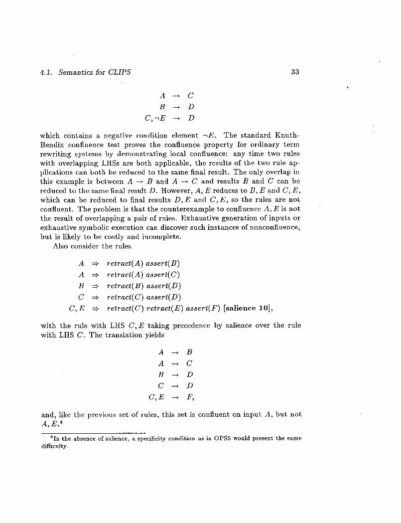
For example, consider the following set of production rules (these are
not in CLIPS syntax):
A =_ retract(A) assert(B)
A =_ retract(A) assert(C)
B =_ retract(B) assert(D)
C,-_E ::> retract(C) assert(D).
These translate into the rewrite rule set
A --+ B
4.1. Semanticsfor CLIPS 33
A --* C
B -+ D
C, _E --+ D
which contains a negative condition element -_E. The standard Knuth-
Bendix confluence test proves the confluence property for ordinary term
rewriting systems by demonstrating local confluence: any time two rules
with overlapping LHSs are both applicable, the results of the two rule ap-
plications can both be reduced to the same final result. The only overlap in
this example is between A --* B and A --* C and results B and C can be
reduced to the same final result D. However, A, E reduces to B, E and C, E,
which can be reduced to final results D, E and C, E, so the rules are not
confluent. The problem is that the counterexample to confluence A, E is not
the result of overlapping a pair of rules. Exhaustive generation of inputs or
exhaustive symbolic execution can discover such instances of nonconfluence,
but is likely to be costly and incomplete.
Also consider the rules
A =_ retract(A) assert(B)
A =_ retract(A) assert(C)
B =_ retract(B) assert(D)
C =v retract(C) assert(D)
C,E =_ retract(C) retract(E) assert(F) [salience 10],
with the rule with LHS C, E taking precedence by salience over the rule
with LHS C. The translation yields
A --* B
A --* C
B --+ D
C --* D
C, E -* F,
and, like the previous set of rules, this set is confluent on input A, but not
A, E. 4
4In the absence of salience, a specificity condition as in OPS5 would present the samedifficulty.
34 Chapter 4. Semantics for CLIPS-Like Languages
That negative condition elements and conflict resolution by specificity
should yield similar difficulties for confluence testing is not surprising, since
sets of rules ordered by salience (or specificity) may be translatable into sets
of rules that do not require conflict resolution by salience by adding negative
condition elements to the more general case rules. For example, translating
the rules C --* D and C, E _ F into C,-_E --+ D and C, E --+ F eliminates
the need for conflict resolution by salience.
Practical determination of confluence and other formal properties of
CLIPS-like systems will probably require further simplifications, such as
eliminating negative condition elements and conflict resolution strategies.
Such simplifications areprobably unacceptable and it may instead be nec-essary to consider more complex, global analyses that can take account of
the finite universe of formulas that may occur in working memory.
4.2 Verifying Properties of CLIPS Programs
The semantics of a CLIPS program are defined by the recursive function
RAC in Definition 4.6 of Section 4.1.1.2, for a given interpretation of the se-
lect function, and a given set of rules. An approximate semantics is obtained
by leaving details of the select function unspecified.
We have postulated [35] that verification of useful properties of CLIPS-
like programs can be performed with respect to such approximate semantics.
In particular, what we might call weak verification establishes properties
that are true of a CLIPS program, independently of the conflict resolution
strategy employed (i.e., true for any interpretation of the select function).
Another way of looking at weak verification is that it allows only those prop-
erties to be proven that are declaratively true--i.e., true without reference
to the operational aspects of rule selection.
4.2.1 Invariant and Transition Properties
Because it must be independent of the conflict resolution strategy, weak
verification cannot generally establish the actual function computed by a
CLIPS program, but it may be possible to establish certain safety prop-
erties, in particular, those that are the conjunction of an invariant and a
transition property. 5 In general, a system invariant is a predicate that is to
5Although not directly relevant here, the notion of "security" can be captured in thisway, and provides an existence proof that significant system properties can, indeed, bemodeled by the simple conjunction of an invariant and a transition property.

4.3. Summary 35
be true of all the reachable states of the system. A transition property is a
predicate on pairs of system states that must be true of all pairs of states
"before" and "after" the execution of a single state transition. In our case,
the state of the system is represented by working memory, and the transi-
tion function is represented by a single "step" of the RAC function (i.e., by
apply(select (W), W)).
Thus, to verify an invariant I, it is necessary to show that I is true of
the initiM working memory W0 and that it is preserved by the application
of any applicable rule:
I(Wo) A (I(W) A applicable(k, tg, W) D I(apply(k, tg, W))).
To verify a transition property T, it is necessary to establish
applicable(k, 8, W) D T(W, apply(k, t9, W)).
4.2.2 Termination
Termination of a CLIPS-like program is equivalent to the termination of the
recursive function RAC given in Definition 4.6 of Section 4.1.1.2. One way
to establish termination of a recursive function is to show that its arguments
decrease in "size" according to some well-founded relation on each recursivecall.
A well-founded relation >> is one that admits no infinite decreasing se-
quences. In other words, there are no sequences Xl, x2, x3,.., such that
Xl _ x2 _)> x 3 _ ....
Thus, a termination condition for our CLIPS-like system is:
3 well-founded relation >> such that
W >> apply(select(W), W).
In other words, the result of applying the selected rule and substitution
to working memory W will always be a working memory strictly smaller
than W, with respect to the well-founded relation >>.
4.3 Summary
In this chapter we have developed a framework for specifying the semantics
of CLIPS-like languages. We applied the framework in two ways. First,

36 Chapter 4. Semantics for CLIPS-Like Languages
we developed a term-rewriting interpretation for rule-based systems and
showed that standard techniques for checking term-rewriting systems for the
Church-l_osser property fail in the presence of conflict resolution strategies.
Second, we developed an approximate semantics by leaving details of the
conflict resolution strategy unspecified, and we showed how this could be
used to prove invariant, transition, and termination properties of CLIPS-
like programs. In the next chapter, we attempt to apply these techniques
to the MMU FDII_ system.

Chapter 5
Static Analysis
This chapter focuses on the verification of declarative MMU FDIR system
properties and on the pragmatics of CLIPS. We look first at the problem
of verifying the MMU FDIR system with respect to a state machine encod-
ing of the desired fault isolation and recovery procedure. This effort fails
because of the dependence of the MMU FDIR system on subtle properties
of the conflict resolution strategy of a particular implementation of CLIPS.
We describe results of experiments with the CLIPS execution cycle under-
taken to characterize these properties. The discovery of execution behavior
that depends on chance implementation factors leads naturally to issues in
pragmatics; in the closing section of the chapter we examine CLIPS support
for basic software engineering practices and suggest its implications for the
MMU FDIR implementation.
5.1 Issues in the Verification of the MMU FDIR
It seems feasible that one could verify a CLIPS program similar to the
MMU FDIR example with respect to the transition property that encodes
the desired procedure for fault isolation and recovery. Specifically, it might
be possible to verify the MMU FDIR. program with respect to the state
diagram given in Figure 3.1. This would be relatively straightforward to do
if states were explicitly and _directly recorded in the working memory and
the rules. For example, a prototypicM rule corresponding to the transition
between states 3 and 7 of Figure 3.1 could be something like:
(defrule state-3
?a <- (state 3)
37
38 Chapter 5. StaticAnalysis
=>
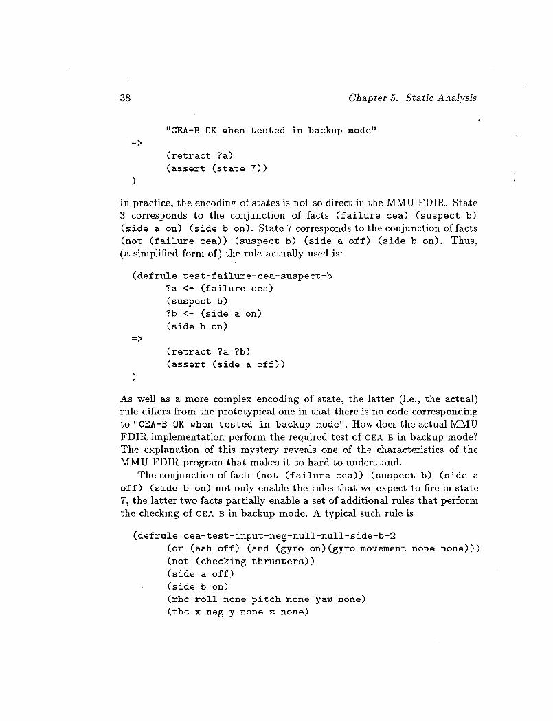
"CEA-B OK when tested in backup mode"
(retract ?a)
(assert (state 7))
In practice, the encoding of states is not so direct in the MMU FDIP_. State
3 corresponds to the conjunction of facts (failure cea) (suspect b)
(side a on) (side b on). State 7 corresponds to the conjunction of facts
(not (failure tea)) (suspect b) (side a off) (side b on). Thus,
(a simplified form of) the rule actually used is:
(defrule test-failure-cea-suspect-b
?a <- (failure cea)
(suspect b)
?b <- (side a on)
(side b on)
=>
(retract ?a ?b)
(assert (side a off))
As well as a more complex encoding of state, the latter (i.e., the actui)
rule differs from the prototypica/one in that there is no code corresponding
to "CEA-B 0K when tested in backup mode". How does the actual MMU
FDIR implementation perform the required test of CEA B in backup mode?
The explanation of this mystery reveals one of the characteristics of the
MMU FDIR program that makes it so hard to understand.
The conjunction of facts (not (failure cea)) (suspect b) (side a
off) (side b on) not only enable the rules that we expect to fire in state
7, the latter two facts partially enable a set of additional rules that perform
the checking of CEA S in backup mode. A typical such rule is
(defrule cea-test-input-neg-null-null-side-b-2
(or (aah off) (and (gyro on)(gyro movement none none)))
(not (checking thrusters))
(side a off)
(side b on)
(rhc roll none pitch none yaw none)
(thc x neg y none z none)
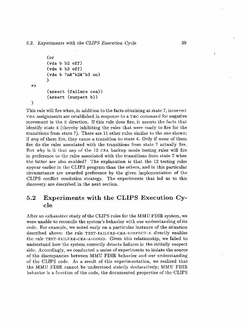
5.2. Experiments with the CLIPS Execution Cyde 39
=>
(or
(vda b b2 off)
(vda b b3 off)
(vda b ?n_-b2_-b3 on)
)
(assert (failure cea))
(assert (suspect b))
)
This rulewillfirewhen, in addition to the factsobtaining at state7,incorrect
VDA assignments are establishedin response to a THC command for negative
movement in the x direction.Ifthisrule does fire,it assertsthe facts that
identifystate 4 (thereby inhibitingthe rules that were ready to firefor the
transitionsfrom state7). There are Ii other rules similarto the one shown;
ifany of them fire,they cause a transitionto state 4. Only ifnone of them
firedo the rules associated with the transitionsfrom state 7 actually fire.
But why is it that any of the 19 CEA backup mode testing rules will fire
in preference to the rules associated with the transitionsfrom state 7 when
the latterare also enabled? The explanation is that the 12 testing rules
appear earlierin the CLIPS program than the others,and in this particular
circumstance are awarded preference by the given implementation of the
CLIPS conflictresolution strategy. The experiments that led us to this
discovery are described in the next section.
5.2 Experiments with the CLIPS Execution Cy-
cle
After an exhaustive study of the CLIPS rules for the MMU FDIR system, we
were unable to reconcile the system's behavior with our understanding of its
code. For example, we noted early on a particular instance of the situation
described above: the rule TEST-FAILURE-CEA-SUSPECT-A directly enables
the rule TEST-FAILURE-CEA-A-GOOD. Given this relationship, we failed to
understand how the system correctly detects failures in the initially suspect
side. Accordingly, we conducted a series of experiments to isolate the source
of the discrepancies between MMU FDIR behavior and our understanding
of the CLIPS code. As a result of this experimentation, we realized that
the MMU FDIR cannot be understood strictly declaratively; MMU FDIR
behavior is a function of the code, the documented properties of the CLIPS
40 Chapter 5. static Analysis
execution cycle, and chance properties of the particular CLIPS implemen-
tation employed.
The properties of interest are those that determine which rule will be
selected for firing when severM rules of equal salience are enabled simulta-
neously. The CLIPS documentation explicitly leaves the choice unspecified
in this case. 1
and
"In CLIPS, rules of equal salience activated by different patterns
are prioritized based on the stack order of facts .... However, if
rules are written that are activated by the same pattern, rule
priority is not guaranteed." [17, p. 119]
"One important point is that if two or more rules having the same
salience are all activated by the same fact, there is no guarantee
of which order the rules will be placed on the agenda." [18, p.
454]
Although the order of rule activations in CLIPS is unspecified in these cir-
cumstances, the implementation of CLIPS appears to use a deterministic
algorithm, and the MMU FDIR system depends on this accidental property
of the implementation.
The property of the CLIPS implementation that appears important to
the MMU FDIlZ system is described in the following annotated outline which
summarizes the results of our experiments with the CLIPS execution cycle.
1. The content of the initial agenda is a function of:
• The order in which facts are input, and
• The basic execution cycle [2, pp. I-5]. 2
The first of these is not explicitly documented, but can be interpreted
as a consequence of the "recency" criterion for rule selection ("the
agenda is essentially a stack" [2, p. I-5]). I_ules enabled by facts
presented later are selected for firing earlier.
1We are grateful to C. Culbert, G. Riley and R. McNenny of the Johnson Space Centerand McDonnell Douglas Space Systems for drawing this to our attention.
2Newly activated rules are added to the top of the agenda unless the salience of the newrule is strictly less than that of the rule at the top of the agenda, in which case the newrule is pushed down the agenda stack until a rule of equal or lower salience is encountered.The new rule is added above those of equal or lower salience.

5.2. Experiments with the CLIPS Execution Cycle 41
Example: if side A facts are entered before side B facts (as in [24]),
B side tests precede the corresponding A side tests. Since the CEA-B
primary mode tests are performed first, the CEA-B recovery tests will
also be performed first. Conversely, if S facts are entered before A
facts, A side tests occur first. Thus, if B facts appear first, the input is
(rhc pitch pos), and sides A and S are both bad in primary mode,
then the initial agenda is as follows:
NO-XFEED-FU EL-CALCU LATION-SIDE-A
NO-XFEED-FU EL-CALCULATION-SIDE-B
CEA-A-TEST-IN PUT-N U LL-POS-N U LL-3
CEA-B-TEST-IN PUT-N U LL-POS-N U LL-3
NO-XFEED-FU EL-READING-TEST-SIDE-A-LSS
NO-XFEED-FU EL-READIN G-TEST-SIDE-B-GRT
N EXT-TO- LAST
VERY-LAST-RULE
2. The contents of subsequent agendas are a function of the above and:
• The order in which the rules are input.
This is an accidental property of the CLIPS implementation; users are
explicitly warned that the order of rule execution is not guaranteed
when rules of equal salience are activated by the same pattern.
In practice, however, and other things being equal, it seems that rules
presented earlier will be selected for firing in preference to those thatcome later. 3
Example: side A is bad in both primary and backup modes for input
(rhc pitch neg).
(a) Order of rules: CEA-Test rules precede CF, A-Recovery rules.
aAccordingly, if two rules are indistinguishable with respect to pattern structure, con-
stants, wildcards, etc., input order prevails. However, if all other things are not equal,
as in the following example due to C. Culbert, G. Riley and R. McNenny, this is not the
case. Thus rules
(DEFRULE AAA (A ?) ----->)
(OEFR_LEBBB (A A) =>)will always be placed on the agenda in the same order when activated by the fact (A A),
independent of their order of presentation.

42
(b)
Chapter 5. Static Analysis
CEA-A-TEST-INPUT-N U LL-N EG-N U LL-4
TEST-FAILU RE-CEA-SUSPECT-A
C EA-TEST-IN PUT-N U L L-N EG-N U L L-SIDE-A-4
TEST-FAILU RE-CEA-A- BAD
PRINT-FAILURE-CEA-A
Result: side A is suspected, tested and found bad.
Order of rules: CEA-Recovery rules precede CEA-Test rules.
CEA-A-TEST-IN PUT-N U LL-N EG-N U LL-4
TEST-FAILU RE-CEA-SUSPECT-A
TEST-FAILU RE-CEA-A-GOOD
TEST-A-CEA-SIDE-B-GOOD
Result: side A is suspected, never tested and declared ok]
Comment: This is an example of v_hat we have referred to as a feed-
ing order between rules. In this case, TEST-FAILURE-CEA-SUSPECT-A assertions allow TEST-FAILURE-CEA-A-GOOD as well as CEA-TEST-
INPUT-NULL-NEG-NULL-SIDE-A-4 to be activated. It is clearly desir-
able that the latter rule fire first, which it appears to do in the MMU
FDIR code, but only because of the serendipitous order in which the
rules are input!
This exploitation of arcane features of the particular implementation of
the CLIPS execution cycle is clearly beyond analysis by approximate
semantics--in which we deliberately omit treatment of the details of conflictresolution.
The experimental outcomes reproduced here raise several fundamental
issues, especially for potentially critical applications such as the MMU FDIR.
First, there is the question of the choice of a programming language whose
support for basic software engineering practices is minimal and whose se-
mantics present a considerable challenge to formal characterization. Second,
there is the issue of using and maintaining a system whose behavioral charac-
teristics are at least partially determined by chance implementation factors.
We consider these and related issues in the following section.

5.3. CLIPS and Software Engineering Issues 43
5.3 CLIPS and Software Engineering Issues
There is a wide variety of programming languages available for conventional
software systems. Although these languages obviously differ with respect to
syntactic structures, semantic properties, and suitability for various appli-
cations, there is uniform acceptance of the need to provide tools to support
basic software engineering practices. Thus the current generation of conven-
tional programming languages almost universally offers data types, abstrac-
tion mechanisms, subroutines, and parameterization. The ideas embodied
in this standard repertoire of features are neither novel nor foreign to the
AI community. Clancy [8], for example, extols the use of abstract control
knowledge in NEOMYCIN; the separation of domain facts and relations
from control knowledge has advantages analogous to the benefits of abstrac-
tion mechanisms in conventional software: the design is more transparent,
the strategies more explicit, and there is a basis for constructing generic
frameworks for related problems in other domains. Jacob and Froscher [21]
focus on modularization, i.e., partitioning the domain knowledge and for-
mally specifying the flow of information between partitions. Ramamoorthy
et al. [31] survey software development support in existing AI development
environments and emphasize the need for software engineering concepts and
life-cycle support for AI programming, where life-cycle refers to the various
development phases including requirements analysis, specification, design
and implementation, usage, and maintenance. By way of elaboration, they
specify that the design phase of the life-cycle should "use software engi-
neering principles such as information hiding, separation of concerns, layer-
ing, and modularity" [31, p. 36]. Buchanan and Smith [4] provide a more
thoughtful characterization of expert systems, including a discussion of ar-
chitectural characteristics of current expert systems and an enumeration of
desiderata for each of several architectural classes. We could go on indefi-
nitely; the AI literature is replete with discussions of software engineering
issues and techniques for rule-based systems.
Given this attention to software engineering issues in AI, it is somewhat
surprising to find that the CLIPS language offers little support for basic soft-
ware engineering practices. Our point is not that CLIPS is without merit;
as noted in the preface to [2], CLIPS is highly portable, relatively low cost,
and can be easily integrated with external systems. And it is not to single
CLIPS out for special criticism--other expert system shells and languages
such as OPS5 [3] have similar defects. What we are suggesting is that cer-
tain characteristics of the MMU FDII% code which detract seriously from its
44 Chapter 5. StaticAnalysis
comprehensibility, and potentially introduce anomalous behavior, are trace-
able in full or in part to the fact that the CLIPS language does not support
basic software engineering mechanisms such as data types, parameterized
procedures, and information hiding.
5.3.1 Pragmatics and the CLIPS Version of the MMU FDIR
In the preceding section we suggested that certain characteristics of the
MMU FDIt_ implementation can be attributed to the level of support for
the pragmatic aspects of software engineering provided in the CLIPS lan-
guage. Of course, not all features of the MMU FDIR implementation are
attributable to the CLIPS language; some features reflect design decisions
which are basically independent of CLIPS. We briefly consider two MMU
FDIR features which exemplify both types of factors.
The MMU FDIR contains seventy-two rules which are functionally very
similar; these rules test CEA input against VDA commands. As suggested
later in Section 5.3.3, this redundancy has implications for efficiency as
well as comprehensibility. In a language which supports subroutines and
parameters, the same functionality could be implemented in a single rule.
Buchanan and Smith [4, p. 35] note that
%.. a representation mechanism that does not allow [information
to be represented as an abstract class] forces designers to con-
front the complexity of stating essentially the same information
many times [which] ... may lead to inconsistency and difficulty in
updating the information [and] ...has an obvious memory cost."
Although it would certainly be possible to introduce a modicum of modular-
ity into the MMU FDII_ design by abstracting the system modes--primary,
backup, gyro--and the basic test function--compare CEA INPUT against
VDA INPUT--CLIPS offers resistance rather than support for such standard
design strategies.
The feature we have elsewhere referred to as embedded procedural knowl-
edge is an example of design philosophy rather than language limitations.
Buchanan and Smith [4, p. 43] note that "one of the defining criteria of
expert systems is their ability to 'explain' their operation." As Buchanan
and Smith point out, it is widely recognized that explanations are useful
for maintenance as well as use of the system. However, it is unlikely that
embedded procedural knowledge can be effectively articulated by an expla-
nation system. The procedurM "states" embedded in the domain knowl-
5.3. CLIPS and Software Engineering Issues 45
edge of the MMU FDIR encode the basic diagnosis and recovery strategy
in an implicit structure which is very difficult to understand and proba-
bly equally if not more difficult to explicate automatically. Buchanan and
Smith [4, p. 35] also caution against this problem; "Impoverished represen-
tation mechanisms force designers to encode information in obscure ways,
which eventually leads to difficulty in extending and explaining the behavior
of expert systems."
One artifact of (the execution of) rule-based programs is the implicit
nature of branching in the control structure. As a result, there is only im-
plicit reference to the branch not taken, i.e., the execution path not selected.
The point is perhaps best made by comparing conventional and rule-based
software paradigms. In conventional software encodings of procedural tasks
both the test and its result are explicit; you know you've done a test, you
know the possible outcomes or branches of the test, and you know which
branch you've taken as a result of the testing. In rule-based encodings of
procedural tasks such as the MMU FDII_, the test is implicit as noted above;
you know a test has been done only because of its side effects--an execution
path has been selected--but you are ignorant of all but the branch or path
selected. 4 As an example, consider the rules for backup mode testing in
the MMU FDIR. If a given CEA is good in backup mode (i.e., its CEA and
VDA inputs are compatible), there is no execution path trace which reflects
the fact that a test has been performed because the test is performed in
the breach; if no backup mode rules apply, the CEA has been "tested" and
found good. In "true" AI programs, the implicit nature of branching reflects
a reasonable separation of domain knowledge/rule base and control strat-
egy/inference engine. In the case of fundamentally procedural programs
such as the MMU FDIR, this separation doesn't exist; the result is to pro-
liferate the use of inhibitory flags and, in general, to further obscure the
functionality of the program.
5.3.2 Static Analysis in the CLIPS Environment
While the CLIPS language is rather impoverished with respect to support
for software engineering, the CLIPS environment is a bit richer; the CLIPS
Cross Reference, Style and Verification (CRSV) utility can be viewed as
4At one level, the alternate branches consist of all the other rules in the rule base!A somewhat higher level explanation is that the alternate paths consist of the possibleexecution paths through that part of the rule base not included in the selected executionpath.

46 Chapter 5. Static Analysis
an attempt to retrofit CLIPS implementations with a modest data typing
mechanism in addition to other capabilities including, as its name suggests,
cross references, style checks, and "verification" against a user defined "stan-
dard." This dichotomy between the language and the environment is nicely
illustrated by one of the enhancements to version 4.3 of CLIPS: a template
structure analogous to record structure in Pascal. Not surprisingly, the pur-
pose of this enhancement is to encourage structured programming, i.e., to fa-
cilitate the definition and use of patterns with explicit structure [17, p. 169].
Each field of the new template structure has an optional type specification
which is used (only) by CRSV! Instead of a limited data typing mechanism
in the language, data typing has been relegated to the CI_SV utility.
The CLIPS-style programming paradigm places no constraints on the
creation of facts; as a result, assertions can be made without any under-
standing of the state space created. In the case of the MMU FDIR, this has
led to assertions of unused facts such as FAILURE CEA-COUPLED, FAILURE
CEA-A-B, FAILURE THRUSTER-A, FAILURE THRUSTER-B, and even FAILURE-
THRUSTERS-WITH-XFEED. The latter is a particularly revealing example,
since it is probably an undetected error; to be consistent with other failure
reports, the assertion should be FAILURE THRUSTERS-WIrFH-XFEED. Fortu-
nately, these types of errors can be detected statically and there are au-
tomatic tools such as the CLIPS CRSV for doing just that. One wonders,
however, how many rule-based programs are actually exposed to static anal-
ysis.
We undertook a static analysis of the MMU FDII_ code using the CLIPS
CRSV utility and other available tools, such as the EMACS search facility.
We focussed on "anomaly detection": a form of static analysis in which one
looks for "suspicious" features such as deadend and unreachable literals and
rules that probably indicate the presence of a fault. We also undertook a
detailed manual inspection to locate redundancy and consistency errors and
to analyze program structure and control flow properties.
The results of our static analyses are summarized in the following anno-tated outline.
• Deadend literals (literals that are asserted but never used): CEA-
COUPLED_ CEA-A-B, THRUSTEK-A, THRUSTER-B.
• Lexical artifacts (analysis of output from Ct_SV revealed the first two
of these):

5.3. CLIPS and Software Engineering Issues 47
- Name duplication: in the machine-readable version of the code
there are two rules named NO-XFEED-FUEL-READING-TEST-SIDE-
B-GRT, the second of which should be NO-XFEED-FUEL-READING-
TEST-SIDE-B-LSS.
-Typographical errors: the rule XFEED-FUEL-READING-TEST-
GENERAL asserts (CHECKING THRUSTER) rather than (CHECKING
THRUSTERS).
The same rule, XFEED-FUEL-READING-TEST-GENERAL, as-
serts (FAILURE-THRUSTERS-WITH-XFEED) rather than (FAILURE
THRUSTERS-WITH-XFEED) which would be consistent with other
failure reports.
- Inconsistent naming conventions: attributes associated with sides
A and B are not uniformly named, e.g., X-FEED-A, FUEL-USED-
A, but TANK-PRESSURE-WAS _ side > and TANK-PRESSURE-
CURRENT < side >.
Similarly, failure sites are reported with two separate predicates:
SUSPECT in the CEA-testing component and CHECKING in the
Tank/Thruster component.
• Semantic artifacts:
-All normal and backup mode GYRO rules assume (AAH ON)
except CEA-A-GYRO-INPUT-ROLL-POSS-6, CEA-B-GYRO-INPUT-
ROLL-POSS-6, GYRO-INPUT-ROLL-POSS-BACKUP-A-6, and GYRO-
INPUT-ROLL-POSS-BACKUP-B-6 which assume (hAil OFF)-
highly suspicious for GYRO rules.
-- The rule XFEED-FUEL-READING-TEST-GENERAL doesn't check for
simultaneous failures; all other fuel reading tests assume (NOT
(FAILURE 7)).
We attribute the number of straightforward anomalies found in the MMU
FDIR program to the lack of data-typing in CLIPS. In the next section we
consider a further issue of pragmatics.
5.3.3 EfFiciency Considerations
In the MMU FDIR documentation [24, p. 8], the authors mention that "the
rules have been designed to increase execution speed," apparently referring
to the single-rule representation of VDA output for all twenty-four thrusters
48 Chapter 5. Static Analysis
for a given tEA input. The rationale is that a rule is fired only in response
to a specific failure, thus the total number of rules fired during diagnosis
is reduced. This approach can be characterized as "state parsimony"; a
potentially large number of (thruster) states is represented in a single rule.
Of course, as noted above, a language which supports parameterization and
subroutines provides a much greater degree of state parsimony. There are
also rule-internal parsimonies such as pattern orders which potentially affect
efficiency. The CLIPS manual [2, pp. II-56-II-57] notes that while there are
no "hard and fast" rules for optimal pattern orders, there are three "quasi
methods" based on the Rete pattern matching strategy used in CLIPS.
1. More specific patterns should precede more general patterns.
2. Patterns with the lowest number of occurrences in the fact-list should
precede those with a larger number.
3. Volatile patterns, i.e., those frequently asserted/retracted, should ap-
pear later rather than earlier.
The CLIPS implementation of the Rete algorithm exploits rule similarity
by creating shared networks for structurally similar rules and shared com-
putations for these common components. Further efficiencies are gained by
limiting particular variable instances to a single pattern, thereby eliminating
cross-pattern variable identity checks. Due to the above noted redundancies
and the resulting specificity of the rules, the MMU FDII_ implementation
should be quite efficient; the fact base is small and for a given set of input
facts there is effectively a single applicable rule. Consider the primary mode
test reproduced below.
(defrule cea-a-test-input-null-pos-null-3
(or (aah off) (and (gyro on)(gyro movement none none)))
(side a on)
(side b on)
(rhc roll none pitch pos yaw none)
(thc x none y none z none)
(or
(vda a bl off)
(vda a f3 off)
(vda a ?na'bla'f3 on)
)
5.3. CLIPS and Software Engineering Issues 49
=>
(assert (failure cea))
(assert (suspect a))
(printout t crlf "failure -during rotational command ")
(printout t "in the pos pitch direction" crlf)
)
This rule is identical to 8/I twenty-four primary test rules except for the
input command (RHC ROLL NONE PITCH POS YAW NONE) and the thruster
configuration patterns. There will be a single computation for the firstthree
patterns 5 when all twenty-four rules are potentially applicable. The network
of "active patterns" is quickly pruned from a network shared by twenty-four
rules, to one shared by two rules when the fourth pattern is considered;
there are only two rules with patterns corresponding to manual input in
primary mode for positive rotation about the pitch axis. Thus a potentia/ly
large network is quickly reduced without reference to variable bindings; no
variables appear in patterns until the last LIIS pattern when at most a
single rule subnetwork is "active." Accordingly_ for the usage phase of the
program life-cycle,the MMU FDIR is a fairly efficient implementation; it
encodes a small state space with highly specific patterns and should execute
reasonably fast.
As always, there are tradeoffs. In this case, execution speed is bought at
the expense of maintainability; the cost of understanding, modifying, and
extending the system is high. Thus ifthe assignment of thruster configura-
tions to inputs should change, a large proportion of the rules would have to
be modified. Similarly, adding or reconfiguring thrusters to accommodate
new inputs would affect a large number of rules.
We end this discussion of software engineering in CLIPS with an ac-
count of a version of the MMU FDIR which we have coded in a high-level 6
procedurM language.
5.3.4 A BASIC Implementation of the MMU FDIR
Following our intuition that the MMU FDII% is fundamentally procedural,
we decided to write an a/ternate version of the MMU FDIR in a mod-
estly endowed procedural language. We chose BASIC as our procedural lan-
guage because, with its limited support for modularity, abstraction, and even
5It is not clear from the discussion in [2] whether the first line of this rule is considered
as one or more patterns.e,,.., a high-level language such as Pascal, Ada, FORTRAN, C, or BASIC" [17, p. v].

50 Chapter 5. Static Analysis
parameterized procedures, it seems the procedural programming language
most similar in capability to expert system notations such as CLIPS.
The experiment had two goals: first, to explore whether a procedural im-
plementation would increase the clarity and decrease the size of the MMU
FDIR implementation; and second, to confirm our understanding of the
CLIPS implementation. The BASIC program, which is reproduced in Ap-
pendix C, has been useful on both counts. Despite the limitations of BASIC,
we were able to encode a reasonably understandable MMU FDIR in approx-
imately 100 lines of code. In contrast, the corresponding MMU FDIR code
consists of 97 rules averaging between 8 and 18 lines each. 7 Furthermore,
experiments with the BASIC program led us to realize that the MMU FDIR
encodes an overly restrictive model of multiple input failure (cf. the remarks
about erroneous CEA inputs at the end of Section 6.1.4).
5.4 Summary
This chapter reports a failed attempt to apply the approximate semantics
developed in the last chapter in order to verify a property of the MMU FDIR
system. The MMU FDIR system is so simple that there is little to verify
other than that it performs the steps of the isolation and recovery procedure
in the correct sequence. When we attempted to perform an informal verifi-
cation of this property, however, we were unable to reconcile the observed
behavior of the FDIR system with either our approximate semantics, or our
understanding of the CLIPS execution cycle. Experiments with the CLIPS
execution cycle showed that the observed (and largely correct) behavior of
the FDIR system was crucially dependent on accidental properties of the
CLIPS conflict resolution strategy: namely, in the particular implementa-
tion of CLIPS used, rules that appear early in the rule base are preferred
to those that appear later. This chapter also reports several inconsistencies
and errors in the MMU FDIR CLIPS code that were discovered by static
anMysis of the program.
We draw two conclusions from the studies reported in this chapter. First,
the common claim that rule-based programming languages are declarative
(e.g., [18, p. 36]), i.e., can be understood without recourse to an operational
7We didn't implement the tank/thruster test partition which consists of 7 CLIPS rules;hence, the disparity between the 104 rules mentioned in the MMU FDIR documentationand the 97 rules cited here. Neglecting comments and blank lines, the CLIPS code forthe 97 rules occupies 1,467 lines. The CLIPS code for the complete MMU FDIR systemis 1,898 lines long, including comments and blank lines.
5.4. Summary 51
model of execution, is a dangerous delusion. It is a delusion because it is
possible to write programs whose properties are partially or even totally
dependent on operational properties of the execution mechanism. It is dan-
gerous because the dependency may not be fully understood, or may not
be explicitly documented, allowing subsequent modifications to perturb the
behavior of the program in unexpected ways. It is even possible that such
programs--exemplified by the MMU FDII_ system examined here--may de-
pend on explicitly unguaranteed properties of the execution mechanism. The
danger is compounded because it is generally unrecognized. Thus statements
such as the following are common [7, p. 415].
"Since the control strategy of the software is contained in the
inference engine, and separated from the knowledge base, a pro-
grammer may have a higher level of confidence in understanding
the effects of changes to the knowledge base. One may make
changes to the knowledge base without worrying about the flow
of control or execution sequences."
Our second conclusion relates to pragmatic issues of software engineering
and coding reliability in CLIPS. The functionality of the MMU FDII_ system
is almost trivial, yet the CLIPS program is quite long, contains several flaws,
and is very difficult to understand. We feel that the prolixity of CLIPS
programs may itself be a source of unreliability. In our opinion, however,
a more significant potential source of unreliability is the lack in CLIPS of
support for serious software engineering practices. Data typing, information
hiding, and parameterized procedures are all absent from CLIPS. The CRSV
tool is a worthwhile step in the right direction but cannot, in our opinion,
compensate for the omitted capability in CLIPS itself.

Chapter 6
Dynamic Analysis
In preceding chapters we have specified requirements for the MMU FDIR,
proposed a formal semantics for CLIPS-style notations, and discussed prag-
matic factors operative in the MMU FDIR implementation. In this chapter
we take the MMU FDIR implementation as given and explore dynamic test-
ing strategies applicable to the MMU FDIR system.
We follow convention in using the general term "testing" to refer strictly
to the notion of dynamic testing, in which program behavior is observed as
a function of program execution. Conversely, static testing refers to analysis
of program text, and possibly related formulations such as requirements and
specifications, independent of execution behavior, as discussed in Chapter
5. The purpose of dynamic testing is to examine the behavior of the sys-
tern over a "reasonable" input sample. Given that the input space of most
programs is intractably large, a sample is typically defined by partition-
ing the input space into equivalence classes whose members are expected
to exhibit similar behavior. One "representative" from each class is then
selected for testing. 1 The equivalence criteria determine which of several
dynamic testing strategies is most appropriate. In the following discussion,
we focus primarily on two strategies: functional or "black-box" testing and
structural or "white-box" testing. We discuss techniques developed for con-
ventional software which also appear productive in the domain of rule-based
AI software and apply them to the task of evaluating the MMU FDIR.
1There are of course alternative ways of defining the input sample (cf., for example,
[34, pp. 29-30]), but the approach mentioned here appears to be the most widely used.
52

6.1. Functional Testing 53
6.1 Functional Testing
The goal of functional testing is to discover discrepancies between the actual
behavior of a software system and the desired behavior described in its func-
tional specification. In functional testing, test data are selected with respect
to a program's function as defined by its requirements, specification and de-
sign documents--so-called program-independent sources. Several functional
testing discussions, including those in [40] and [29], also cite the importance
of program-dependent sources, including the code itself. In any case, the
relevant sources are used to provide a functional specification which can be
viewed as a typically unspecified or only very generally specified relation
F on I x O for input domain I and output domain O. Input and output
domains are usually partitioned into groups or classes based on the relevant
documents or program-independent/dependent sources; given a certain class
of input, a certain class of output results, i.e., F(i, o), for i E I, o E O. Typ-
ically, test data are selected which cover the input and output domains,
i.e., input data are chosen which lie well within or just inside/outside the
boundaries of each class i E I, and produce output representative of eachclass o E O.
The general approach of functional testing is directly applicable to rule-
based AI software. Of course specific techniques which rely on careful or
perhaps even formal specification are less applicable, given the development
paradigm for most rule-based software. We have concentrated on a synthesis
of two techniques: an adaptation of the "revealing subdomains" method
mentioned above [40] and a variation on random testing in the spirit of
[19,20].
6.1.1 Revealing Subdomains
As noted in [40], the basic intuition behind the notion of revealing subdo-
mains is quite simple; elements of a subdomain behave identically---either
every element produces correct output, or none does. In particular, test
criterion C is revealing for a subset S of the input domain if whenever any
element of S is processed incorrectly, then every subset of S which satisfies
C fails to execute successfully. Let the predicates OK and SUCC denote
successful execution of an element of S and a subset of S, respectively. The
formal statement of the preceding intuitive definition is as follows.
REVEALING(C, S) iff
(3d E S)(-_OK(d)) ==>(VT C S)(C(T) =¢. -_SUCC(T)) [40, p. 239]

54 Chapter 6. Dynamic Analysis
Unfortunately, as Weyuker and Ostrand also note, running successful
tests from a revealing subdomain S does not in general guarantee that the
program is correct on S; such guarantees are purchased only at a cost equiv-
alent to that of a proof of correctness for the subdomain. On the other hand,
we can guarantee that S is revealing for certain specified errors E. A sub-
domain S is revealing for an error E if for a program F, such that E is an
error in F and E affects some element of S, every element s E S is affected,
i.e., --OK(s) [40, p. 239]. Thus, the correct execution of an element from a
revealing subdomain guarantees the absence of the specified error on that
subdomain. Of course the incorrect execution guarantees only that some
(though not necessarily the specified) error has occurred.
Revealing subdomains are constructed by a two-part process as follows.
The first step consists of partitioning the input domain into sets of inputs,
each of which follows the same or a family of related paths through the pro-
gram. In conventional software, the partition is based on the program's flow
graph. For AI software, either an execution graph or reasonable facsimile
will suffice. The second step consists of specifying the problem partition and
is somewhat less well defined. Weyuker and Ostrand [40, p. 240] state only
that partitions should be formed "on the basis of common properties implied
by the specifications, algorithm, and data structures." To supplement this
somewhat vague directive, we adapt the first three steps of the category-
partition method for specification-based functional tests developed by Os-
trand and Balcer [29, p. 679]. 2 Using only program-independent sources,
these steps include
1. identify individual functional units which can be separately tested and
for each unit identify and characterize parameters and objects in the
environment crucial to the unit's function;
2. partition the elements identified in 1 into distinct cases;
3. determine constraints, if any, among the cases identified in 2.
Whatever its precise method of discovery, the purpose of the problem par-
tition is to separate the problem domMn into classes which are in theory
equivalent with respect to the program, whereas the purpose of the path
domains is to separate the problem domain into classes which are in fact
2The process enumerated below constitutes only the preliminary analysis suggestedby Ostrand and Balcer who describe a method for creating functional test suites using agenerator tool to produce test descriptions and scripts.

6.1. Functional Testing 55
treated identically by the program. Revealing subdomains are defined as the
intersection of the two classes, i.e., as equivalence classes of input domain
elements which are processed identically by the program and characterized
identically by program-independent specifications. By definition, each such
subdomain has the property that either all or none of its elements are pro-
cessed correctly. It follows that the actual test data need only consist of an
arbitrary element from each subdomain.
6.1.2 Random Generation of Test Data
In a survey of automatic generation of test data, Ince [19] observes that sys-
tematic use of randomly generated test data potentially provides reasonable
coverage at low cost. The idea, subsequently elaborated in a short note by
Ince and Hekmatpour [20], exploits preliminary results independently noted
in [12] which indicate that relatively small sets of random test data do ap-
pear to provide good coverage. For programs such as AI rule-based software
systems which typically have little if any program-independent documenta-
tion, random generation of test data seems particularly promising. Although
we have randomized the test data for MMU FDIR testing (cf. Section 6.1.4)
and note the intuition that this technique appears equally appropriate for
both conventional and AI software, we feel additional tests on various types
of rule-based programs are necessary to confirm the applicability of this
testing technique to rule-based systems.
6.1.3 A Synthesis
An obvious alternative to either of the techniques mentioned in Sections
6.1.1 and 6.1.2 is their combination. Ideally, this synthesis focuses the low-
cost, good-coverage benefits apparently associated with random generation
of test data on functionally relevant classes of input identified by the reveal-
ing subdomains method. Additionally, the path domains specified by the
revealing subdomains method provide a built-in criterion for evaluating the
coverage of the randomly generated test data. We discuss the application
of this hybrid technique to the MMU FDIP_ in the following section.
6.1.4 MMU FDIR Evaluation I: Functional Testing Tech-
niques
The MMU FDII_ system has two independent test partitions: CEA tests
and tank/thruster tests. The latter is very rudimentary, consisting of three
56 Chapter 6. Dynamic Analysis
rules each for sides A and B, and encodes a highly simplistic model of
tank/thruster failure. We have chosen to ignore the tank/thruster test par-
tition in the following discussion.
To begin, we need to define the input domain. MMU FDIR inputs consist
of translational, rotationM and gyro commands, and C_,A, thruster, GYR.O
and AAH settings. Accordingly, let the input domain I = {vda-input, cea-a,
cea-b, cea-gyro, cea-aah, {cea-cmd)}, where vda-input represents the on/off
settings of the 12 VDA thrusters for each of sides A and B, cea-a, cea-b, cea-
gyro, cea-aah represent the on/off settings for side A, side B, GYRO, and AAH,
respectively, and cea-cmd represents the possibly empty set of input com-
mands, i.e, zero, one, or more of thc, rhc, and gyro movement commands.
The first task is to partition the input domain into path domains, each of
which follows a distinct path through the MMU FDIlZ code. There are two
obvious candidates: null and nonnull input. In additional, we have the do-
main paths corresponding to the possibilities that both A and B are good in
primary mode and A or B or both is/are bad in primary mode. Given the last
possibility, there are four additional path domains, depending on whether
A and S are good or bad in backup mode. There is a further consideration.
Although duals of one another, the fault identification and recovery rules
for sides A and S represent disjoint paths through the MMU FDIR code;
the order in which the fault is detected determines which of the two sets of
paths will be exercised. Accordingly, we need to add four additional path
domains. We have now distinguished a total of eleven path domains. The
claim is that for any combination of inputs in the input set, one of these
eleven path domains will be selected, and moreover each of the domains can
be identified with a particular class of identically behaved inputs.
The second task is to create problem partitions. We use the category-
partition method, relying solely on program-independent sources which in
this case are limited to the documentation accompanying the MMU FDII_
code [24]. MMU functional units which can be separately tested and their
essential contexts are as follows: primary and backup modes for both CP,A
and GYlZO, and fault identification and recovery 3.
On the basis of the MMU FDII_ documentation, there is no reason to
combine any of the functional units into a single case. However, there is
motivation for distinguishing five functional units for each of the two sides,
CEA-A and CEA-B [24, p. 10]. Hence step 2 generates ten cases for the five
functional units identified in step 1. Step 3 whose purpose is to distinguish
3The documentation refers to this function as "failure and recovery."

6.1. Functional Testing 57
constraints among the cases derived in step 2 yields no further refinement.
The MMU FDIR problem partitions identified by this category-partition-
style analysis are displayed in the table below.
Functional Unit Parameters
side a primary mode input set I
side a primary gyro mode input set I
side a backup mode I-t- new cea-a g= cea-b, suspect-a/b
side a backup gyro mode Iq- new cea-a _ cea-b, suspect-a/b
failure-cea-a/b
side a fault identification gz recovery cea-a, cea-b,
suspect-a/b, failure-cea-a/b
side b primary mode input set I
side b primary gyro mode input set I
side b backup mode I-t- new cea-a _= cea-b, suspect-a/b
side b backup gyro mode I-l- new cea-a gz cea-b, suspect-a/b
failure-cea-a/b
side b fault identification &=recovery cea-a, cea-b,
suspect-a/b, failure-cea-a/b
Table 6.1: MMU FDIR Problem Partitions
To define the revealing subdomains for the MMU FDIR, we intersect
the eleven path domMns with the ten problem partitions. Weyuker and
Ostrand [40, p. 240] suggest that potential errors lurk in precisely those
places where the two analyses differ, a point nicely illustrated by the MMU
FDIR, given that the distinctions contributed by the two analyses are some-
what orthogonM. The reconciliation proceeds as follows. 4 The problem
partition distinguishes GYRO from CEA input in primary mode, a distinction
which is vacuous in practice because all primary mode failures are processed
identically, i.e., regardless of the particular values of the input set I, all
primary mode failures signal a failure and identify the side suspected of fail-
ing. The same argument can be made with respect to backup mode; backup
mode analysis proceeds identically for both GYRO and CEA. Furthermore,
the distinction between sides A and B is relevant only for fault identifica-
4We are not concerned here with correct encodings of CEA or GYrtO input and VDAinput. Errors of this kind can be detected statically.

58 Chapter 6. Dynamic Analysis
tion and recovery, i.e., precisely at the point identified in the path domains.
The remaining distinctions contributed by the problem partition are entirely
subsumed by those identified by the path domains. Accordingly, we define
the revealing subdomains of the MMU FDIR input domain as follows. We
distinguish three initial subdomains with respect to the cardinality of the
set of input commands. The intuition is that all inputs of the form {vda-
input, cea-a, cea-b, cea-gyro, cea-aah, { }} for arbitrary values for all but
the set {cea-cmd), which is null, behave identically, and similarly for the
case card{cea-cmd} > 1, i.e., the case of multiple input commands. For
card{cea-cmd} = 1, we further distinguish nine subdomains corresponding
to the single case where sides A and B are both good in primary mode and
the following eight cases where at least one side is bad in primary mode and
the backup modes are as indicated: A bad, S bad; S bad, A bad; A bad, S
good; B bad, A good; A good, B bad; B good, A bad; A good, B good; S good,
A good. We summarize the final results of the analysis in the table below,
which displays the eleven revealing subdomains and associated errors. Let
'+' indicate good and '-' bad, e.g, the entry "primary:a- or b-; backup: a+,
b-" represents the case where either A or S (or possibly both) has failed
in primary mode and A is good, and S bad, in backup mode. Each error
entry is assumed to have the preface "failure to detect"; e.g., the entry "null
input" should be read "failure to detect null input."
For actual testing we focused on the identification and recovery paths for
a single side , i.e., we concentrated on seven of the eleven revealing subdo-
mains. In particular, we ran exhaustive tests on the above-mentioned seven
subdomains in order to confirm our subdomain analysis, and tested a lim-
ited number of cases for each of the other four subdomains as prescribed by
the subdomain strategy. The test cases for the exhaustive trials were gen-
erated automatically, using a random test case generator. More specifically,
we wrote an automatic test generator which output test facts for all pos-
sible thruster combinations over all possible single inputs given a specified
number of active thrusters. Using this output, a Unix script, and a version
of the MMU FDIR. modified to output fault codes, we tested thousands of
cases. A summary of all test results appears in the table below. The "tests"
column indicates whether the test cases were limited (L, i.e., two-five cases)
or exhaustive (E) and the "result" column indicates one of three possible
outcomes: the MMU either failed to terminate or terminated abnormally
(*); the MMU terminated but the execution was in some way anomalous
(?); the MMU executed successfully (ok).

6.1. Functional Testing 59
Subdomain Error
card(cea-cmd) = 0 null input
card(cea-cmd) > 1 multiple inputs
card(cea-cmd) = 1 _ primary: a+, b+ primary good
card(cea-cmd) = 1 &=primary: a- or b-;backup: a+,b+ error coupledb on, a off
card(cea-cmd) = 1 & primary: a- or b-; backup: b+,a+ error coupleda on, b off
card(cea-cmd) = 1 &: primary: a- or b-; backup: a-,b- abortboth failed
card(cea-cmd) = 1 &: primary: a- or b-; backup: b-,a- abortboth failed
card(cea-cmd) = 1 _ primary: a- or b-; backup: at,b- a ok, b bad
card(cea-cmd) = 1 _= primary: a- or b-; backup: b+,a- b ok, a bad
card(cea-cmd) = 1 _ primary: a- or b-; backup: a-,b+ a bad, b ok
card(cea-cmd) = 1 &=primary: a- or b-; backup: b-,a+ b bad, a ok
Table 6.2: Revealing Subdomains for the MMU
The MMU FDII_ failed to execute successfully on four of eleven subdo-
mains. The abnormal behaviors for eard(cea-cmd) _ 1 result from the failure
to discharge in the code the explicit assumption [24, p. 7] that all command
inputs are single rotational, translational or gyro directives. In the case of
card(cea-cmd) = 0, the appropriate rules exist, but result in an infinite loop,
whereas in the case of card(cea-cmd) > 1 there are no rules in the rule base
and the MMU FDII_ accepts as good any combination of wild and wonder-
ful CEA inputs and VDA commands. We see this as symptomatic of a more
general problem, namely the strategy of modeling incorrect MMU behavior
by inverting the VDA input (i.e., commands) while ignoring potentially un-
desirable combinations of inverted CEA inputs. Consider the example where
CEA input and VDA input commands are as given below.
• CEA Input: AAH on, GYRO of[, gyro-movement none, rhc none, thc z
pos, A on, B on.

6O Chapter 6.
Subdomain
eard(cea-cmd) -- 0
card(cea-emd) > 1
card(cea-cmd) = 1 _ primary: a-t-, b+
card(cea-cmd) = 1 &: primary: a- or b-; backup: a+,b-t-
card(cea-cmd) = I _: primary: a- or b-; backup: b+,a+
card(cea-cmd) = 1 &: primary: a- or b-; backup: a-,b-
card(cea-cmd) = 1 &=primary: a- or b-; backup: b-,a-
card(cea-cmd) = 1 &: primary: a- or b-; backup: a+,b-
card(cea-cmd) = 1 _ primary: a- or b-; backup: b+,a-
card(cea-cmd) = 1 _ primary: a- or b-; backup: a-,b+
card(cea-cmd) = 1 _ primary: a- or b-; backup: b-,a+
Dynamic Analysis
Tests[ Result
E *
E
E ok
L ok
E ok
L ok
E ok
L ?
E
L ok
E ok
Table 6.3: Results of MMU FDIR Subdomain Testing
• VDA Input: side A: bad in both primary and backup mode 5, side B:
ok in both primary and backup mode.
Given this scenario, the MMU FDIR reports both sides good in primary
mode, i.e., falls to recognize the faulty (side A) VDA input because the
MMU FDIR doesn't check for abnormal CEA input. 6 The other two cases of
anomalous behavior arise when the side suspected of failure is ok in backup
mode, resulting in a report of "failure cea-coupled" before the second side
is checked. The system eventually checks the second side and recovers ap-
propriately, but the initial coupled failure report is erroneous.
We began this section with a discussion of functional testing techniques
and concluded with an application of revealing subdomalns. The latter
technique actually uses a mixed black-box, white-box strategy insofar as
path domains reflect structural characteristics and problem partitions reflect
functional specifications. In the next section we look more closely at strictly
white-box or structural testing techniques.
SOur test had only one of the two required side A thrusters on.
6The input in this example---AAH on, GYRO off, and THC z pos--is obviously nonsense,
but arbitrary malfunctions can lead to implausible as well as plausible yet erroneous input
combinations. Clearly, abnormal input of any kind should be detected and reported. Cf.
Appendix B for a log of this example.
6.2. Structural Testing 61
6.2 Structural Testing
The goal of structural testing is to expose run-time errors by exercising
certain critical execution paths through the program. Execution paths are
typically defined with respect to the program's control flow graph; paths
are selected on the basis of criteria such as all nodes, all edges, or some
combination of nodes and edges. Several researchers have shown that the
most effective path selection criteria exploit context, i.e., data- as well as
control-flow properties of the program [32,28] and Clarke et al. [9] provide a
formal evaluation of these and other criteria based on data-flow relationships.
While the necessity of both data- and control-flow-based properties appears
firmly established, Clarke and her colleagues note that additional studies are
needed to consider issues such as the relative cost and detection capabilities
of the various path selection criteria.
Unfortunately, the notion of path criteria for rule-based systems is some-
what problematic. There are basically two issues: a productive definition
of execution path and, given that, effective path selection criteria, which we
discuss in the order given.
6.2.1 A Definition of Execution Path for Rule-Based Soft-
ware
As noted, the notion of execution path is well defined for conventional soft-
ware, but decidedly ill-defined for rule-based software. This is the case for
several reasons. First, rule bases have both "declarative" and control flow
elements; despite the frequent claim that rule bases are strictly declarative,
there is often implicit encoding of control information. 7 Thus to the extent
that rule bases are declarative, the notion of execution sequence is prob-
lematic, and to the extent that control information is implicit, control flow
is often difficult to understand and characterize. Second, if a rule-based
system is considered independently of the associated inference engine, its
execution is nondeterministic, further complicating the notion of path.
What, then, is a suitable notion of path for rule bases? There are clearly
several desiderata. The notion should be compositional, i.e., it should spec-
ify elementary connections between rules and define paths as their transitive
closures. Additionally, implicit control flow information should be made ex-
plicit. Note that unlike conventional software, where all branches of a pred-
7The MMU FDIR is a good example; control flow is implicit in the use of "flags" suchas SUSPECT-A,SUSPECT-B, FAILLrRE-CEA, SIDE-A-ON, and SIDE-B-OFF.
62 Chapter 6. Dynamic Analysis
icate or test construct are explicit, rule-based software tends to explicitly
represent only the 'successful' branch; rules which are not enabled are effec-
tively ignored, s Finally, the notion should focus on relevant execution flow
information as opposed to low-level connectivity relationships. The litera-
ture includes several proposals for "execution graphs" for rule bases, two of
which have been specifically proposed as a basis for structure-based testing,
namely the approaches proposed by Stachowitz et al. [38] and Kiper [22].
6.2.1.1 Proposals Extant in the AI Literature
Stachowitz and colleagues specify a Rule Flow Diagram which is in turn
derived from a Dependency Graph (DG). A dependency graph is a represen-
tation for facts and rules in a knowledge base, where an arc in the graph
denotes that a literal in the conclusion (I_HS) of rule a unifies with a lit-
eral in the antecedent (LHS) of rule b. Facts are simply rules with empty
antecedents: The intuition behind the dependency graph is that an arc con-
nects rules a and b just in case firing rule a can lead to the firing of rule b.
For example, there would be an arc from a to b in the DG representation of
the following rules.
a: AAB--+XAZ
b: XAY--+C
However, there are difficulties with this graph specification. For example,
firing rule a above clearly does not enable the following rule, despite the fact
that rules a and b_ satisfy the arc criteria for DGs.
bl : X A-_Z-+ D
A further problem is the apparently unpublished technique for deriving rule
flow diagrams from dependency graphs. In rule flow diagrams, nodes rep-
resent rules and arcs represent execution sequences. The question is, where
8The test and recovery section of the MMU FDIR rule base illustrates this point nicely.
When a fault has been diagnosed on side h in primary mode, the system enters the recoverysection via rule TEST-FAILURE-CEA-SUSPECT-A. At this point an inhibitory flag, SIDE-B-
OFF, forces the system into backup mode. Logically speaking, the system then reteststhe given thruster combination using the backup mode configuration. There are twopossible outcomes, hence two branches: the thruster configuration is either good or bad.
However, if the thruster configuration is good, the execution path never explicitly reflectsthe fact that the configuration has been tested; i.e., the execution path exhibits a directconnection from rule TEST-FAILUR.E-CEA-SUSPECT-A to rule TEST-FAILURE-CEA-A-GOOD.
What has happened, of course, is that the test for configuration failure is not satisfied,
i.e., the path implicitly represents the failure branch of the test.
6.2. StructurM Testing 63
does the sequencing information come from? Stachowitz et al. appear to
suggest that rule flow diagrams can be generated directly from DGs with-
out additional information, but this is surely not the case, as the following
example illustrates. 9 The rule set is based on an example in Kiper [22, p. 7].
1 : A---_B
2 : B-+C
3 : BAC-+D
4 : A-+D
5 : CAD-+E
It is difficult to see how a rule flow diagram generated strictly from the
DG would reflect the appropriate execution sequence in which rules 2 and 4
jointly enable rule 5. Furthermore, assuming such a procedure exists, it is
not clear that it produces a generally satisfactory result; if rule sequencing
rather than some notion of causMity is the criterion on arcs, information
such as the fact that rules 2 and 4 jointly enable rule 5 could be lost.
Finally, and perhaps most important, the DG appears useless for rule-
based systems characterized by (re)occurrences of a given set of literals in
a large number of rules. In the worst case all rules would be connected;
in less extreme cases, however, the problem of excessive connectivity is still
significant. The MMU FDIR is a prime example of this type of system; the
DG for the MMU FDII_ exhibits strong connectivity and virtually no useful
program flow information.
The DG, rule flow diagram pair appears to be the most widely cited of
the rule-based analogues to execution graphs, but as suggested above, it is
somewhat less than satisfactory. We turn now to the alternative proposed
by Kiper.
Kiper [22] suggests a graph construction which explicitly represents the
notion of causality. In these graphs, nodes represent rules and arcs denote
the relation "enables." Specifically, rule i enables rule j just in case the
firing of rule i results in rule j's addition to the agenda. Note that an arc in
this type of graph specifically does not mean either that as a result of rule
i firing, rule j will fire, or that the I_HS of rule i unifies with a condition
on the LHS of rule j. What it does mean is that the cumulative effect of
9Curiously, in the only published test case we could find [6, p. 3], it is not at all clearhow the flow diagram is derived from the rule base; no DG is provided and arcs appearfrom rule 2 to rules 5,6,7,8 despite the fact that there are no literals common to rules 2and 5-8 in the example given in [6, p. 3].
64 Chapter 6. Dynamic Analysis
the chain of rules ending in rule i is to cause rule j to be added to the
agenda, and moreover the conditions for j to fire were not satisfied prior to
the firing of rule i. In addition, Kiper explicitly represents conjunction and
disjunction. Thus Kiper's graph of the preceding five rules would reflect the
fact that rules 2 and 4 jointly enable rule 5. More important, Kiper's graph
construction is based on a criterion which specifies that the representation
for rule bases be independent of any inferencing mechanisms. We think this
is a useful criterion. Nevertheless, there appears to be a serious drawback to
Kiper's representation: in general, it is not conveniently computable. This
follows from the fact that there is no locality condition on arcs; i.e., the
existence of an arc from rule i to rule j is a function of the entire path up
to and including rule i. For example, consider the two rules below, where
the existence of an arc from rule 1 to rule 2 depends on whether the path
leading up to rule 1 has already established Y.
1: AAB---+ X
2: XAY---+ Z
To summarize, we have analyzed two candidates for graphing the ana-
logue of execution paths for rule-based systems and found both to be defi-
cient with respect to the criteria of compositionality, explicit representation
of control flow, and effective representation of information flow proposed
at the beginning of this section. In the following section we suggest an
alternative notion of execution path for rule-based systems.
6.2.1.2 An Alternative Proposal
The notion of execution path proposed below for rule-based systems reflects
execution sequencing and information flow at the level of rule interaction.
Note that this differs fundamentally from the notion of control flow typically
graphed for conventional software, which reflects sequencing between state-
ments and more fine-grained information-flow, i.e., data-flow properties. For
example, control flow graphs for conventional software explicitly represent
loop statements, whereas our representation ignores loops and other rule-internal constructs. 1°
An execution flow graph for a rule-based system S is a (not necessarily
unique) directed graph G(S) = (N, E, N_, N/), where N is the (finite) set of
1°Of the three extant AI-based graph representations, only Stachowitz et al. graph rule-internal constructs. As noted in Section 6.2.1.1, this granularity has certain drawbacks.
6.2. Structural Testing 65
nodes, E C N × N is the set of edges, and Ni C N, N/ C N are the sets of
initial and final nodes, respectively. Each node in N represents a rule in the
rule base of S. For each pair of distinct nodes m and n in N which satisfy
constraints C on the rules represented by m and n, there is a single edge
(m, n) in E. The constraints, C, are as follows:
1. for every predicate p which appears as the outermost symbol of a term
in both the RHS of m and the LHS of n, the two occurrences of p
must unify;
2. the LHS of m is consistent with the LHS of n; i.e., the LHSs of thetwo rules exhibit no overt contradictions. 11
In this initial formulation, there are no edges of the form (n, n).
An execution flow graph defines the rule-execution sequences or paths
within a system S. A subpath in G(S) is a finite, possibly empty sequence of
nodes p -- (nl, n2,..., nlen(p) ) such that for all i, 1 < i < fen(p), (n_, ni+l) E
E. We denote the set of all paths in G(S) as PATHOS). A cycle is a
subpath of length > 2 which begins and ends at the same node. The graph
G(S) is well-formed iff every node in N occurs on some path p C PATHS(S)
and G(S) contains no cycles. 12
Let's see how well the proposed graph formalism handles the previous
examples, which we reproduce below.
a: AAB--_XAZ
b' : X A-_Z--* D
This case is straightforward; Mthough the DG representation erroneously
includes an edge from rule a to rule b', the edge is ruled out by constraint 2 in
our graph formalism. The next case, derived from an example in Kiper [22],
is more challenging. Consider the now familiar rule set below.
1 : A--+B
2 : B--_C
3 : BAC---_D
11For computational reasons, we don't want to check the consistency of the LHSs of
the transitive closure of all rules reachable from m, but it might be productive to set some
experimentally determined bound, e.g., check all rules in the length i subpath terminating
at m.
12The no cycle condition is probably too restrictive, but there is clearly a large class of
systems, including the MMU, which satisfy this constraint.

66 Chapter 6. Dynamic Analysis
4 : A---+D
5 : CAD----_E
Due to the fact that each rule has a single term RHS, our graph and the
DG for this example are identical and appear as shown below.
Figure 6.1: Execution Flow Graph for Kiper Rule Set
As given, the graph illustrates three paths which do not correspond to
possible execution sequences: [1,2,5; 1,3,5; 4,5]. However, if we postprocess
the graph, drawing an arc as shown below between the edges of all nodes
which jointly satisfy the LHS of their common immediate successor 13, the
graph exhibits all and only the correct execution paths for the given ruleset. 14 We don't bother to formalize this postpass condition since it is not
necessary for the MMU FDIR rule base.
13Node j is an immediate successor of node i just in case there is an edge from i to j.
14We could further stipulate that equivalent paths such as [1,2,3,5] and [1,2+3,5] be
"collapsed." It seems likely that the postpass will have to be more sophisticated to han-
dle other less immediate relations between rules. An alternative is to add additional
constraints to the constraint set C.
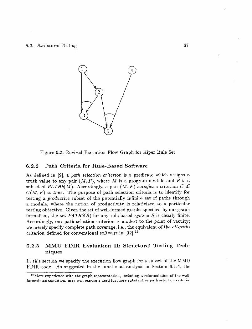
6.2. Structural Testing 67
Figure 6.2: Revised Execution Flow Graph for Kiper Rule Set
6.2.2 Path Criteria for Rule-Based Software
As defined in [9], a path selection criterion is a predicate which assigns a
truth vMue to any pair (M, P), where M is a program module and P is a
subset of PATHS(M). Accordingly, a pair (M, P) satisfies a criterion C iff
C(M,P) = true. The purpose of path selection criteria is to identify for
testing a productive subset of the potentially infinite set of paths through
a module, where the notion of productivity is relativized to a particular
testing objective. Given the set of well-formed graphs specified by our graph
formalism, the set PATHS(S) for any rule-based system S is clearly finite.
Accordingly, our path selection criterion is modest to the point of vacuity;
we merely specify complete path coverage, i.e., the equivalent of the all-paths
criterion defined for conventional software in [32]. 15
6.2.3 MMU FDIR Evaluation II: Structural Testing Tech-
niques
In this section we specify the execution flow graph for a subset of the MMU
FDIR code. As suggested in the functional analysis in Section 6.1.4, the
1SMote experience with the graph representation, including a reformulation of the well-formedness condition, may well expose a need for more substantive path selection criteria.
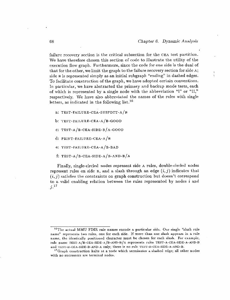
68 Chapter 6. Dynamic Analysis
failure recovery section is the criticM subsection for the CEA test partition.
We have therefore chosen this section of code to illustrate the utility of the
execution flow graph. Furthermore, since the code for one side is the dual of
that for the other, we limit the graph to the failure recovery section for side A;
side B is represented simply as an initial subgraph "ending" in dashed edges.
To facilitate construction of the graph, we have adopted certMn conventions.
In particular, we have abstracted the primary and backup mode tests, each
of which is represented by a single node with the abbreviation "I" or "II,"
respectively. We have also abbreviated the names of the rules with single
letters, as indicated in the following list. 16
a: TEST-FAILU RE-CEA-S USPECT-A/B
b: TEST-rA,LURr,-CEA-A/B-GoOD
C: TEST-A/B-CEA-SIDE-B/A-GOOD
d: PRINT-FAILU RE-CEA-A/B
e: TEST-FAILU RE-CEA-A/B-BAD
f: TEST-A/B-CEA-SIDE-A/B-AN D-B/A
Finally, single-circled nodes represent side A rules, double-circled nodes
represent rules on side B, and a slash through an edge (i,j) indicates that
(i, j) satisfies the constraints on graph construction but doesn't correspond
to a valid enabling relation between the rules represented by nodes i and
j.17
16The actual MMU FDIR rule names encode a particular side. Our single "slash rule
name" represents two rules, one for each side. If more than one slash appears in a rule
name, the identically positioned character must be chosen for each slash. For example,
rule name TEST-A/B-CEA-S1DE-A/B-AND-B/A represents rules TEST-A-CEA-SIDE-A-AND-B
and TEST-B-CEA-SIDE-B-AND-A only; there is no rule TEST-B-CEA-SIDE-A-AND-B.
17Graph construction halts at a node which terminates a slashed edge; all other nodes
with no successors are terminal nodes.

>0
<i
<
r,.)
c_
0
XN
N?o_-,_

70 Chapter 6. Dynamic Analysis
The graph for CEA-A failure recovery encodes the following analysis.
First, there are basically four execution paths through the code:
1. [I,a,b,II,e,II,f] 18 (sides A and B both bad in backup mode);
2. [I,a,b,II,c] (sides A and S both good in backup);
3. [I,a,b,c,II,e,d] (side B bad, A good in backup mode);
4. [I,a,II,e,d] (side A bad, B good in backup).
These paths are precisely those predicted revealing by the preceding
functional analysis. Interestingly, the graph construction identifies eight
additional paths which do not correspond to actual execution sequences.
These are potential error sites and need to be examined. As it turns out, two
of the eight are artifacts of poor coding conventions; paths [I,a,b,d,...] and
[I,a,II,e,c,...] occur because the MMU FDIR uses two distinct flags, C_.A-
A-GOOD and FAILURE CEA-A, rather than a single flag and its negation to
indicate the presence/absence of CEA-A failure. The other six "undesirable"
paths result from the generality of our graph constraints which don't reflect
the context in which a particular rule set operates. For example, if we add
an MMU FDIlZ-speciflc constraint specifying that at most one side can be
suspect, i.e., -n(SUSPECT A A SUSPECT S), several of these undesirable paths
would be eliminated. Eliminating all six undesirable paths merely involves
a small number of additional constraints. The MMU FDIR example clearly
suggests the need for at least minor contextualization of execution flow graphconstruction.
In closing, we would like to emphasize the productivity of this tech-
nique both in isolation and in conjunction with the functional and hybrid
functional-structural techniques discussed earlier. In light of Sections 6.1
and 6.2 it should be quite clear that independent, mutually confirming anal-
yses are extremely useful for isolating potential anomalies.
6.3 Summary
We have identified testing techniques for conventional software which appear
equally applicable to rule-based AI software and have provided constructive
18For obvious reasons, we regard the path [I,a,II,e,II,f] as a variant or related path ratherthan an additional path.
6.3. Summary 71
proof of their usefulness with respect to the MMU FDIR code. These func-
tional and structurM techniques have served two purposes: first, they have
exposed serious as well as benign malfunctions in the MMU FDII_ implemen-
tation, and second, they have increased our understanding and confidence
in the encoding of those parts of the MMU FDIR system which appear to
function as informally specified in the MMU FDIR documentation.

Chapter 7
Summary and Conclusions
As recounted in the preceding chapters, we have used the MMU FDIR as
a vehicle for exploring general issues in the specification and evaluation of
rule-based AI software. Our singular focus on the MMU FDIR has led to
certain tradeoffs. On the one hand, the basically procedural and overly sim-
plistic nature of the MMU FDIR has limited the applicability of specification
techniques we had hoped to explore. On the other hand, the procedural na-
ture of both the task and its encoding have led us to rethink some of our
earlier proposals. Our hope is that both the general techniques developed in
the course of our detailed study of the MMU FDIR and the implementationerrors discovered will be useful to others.
In the remaining sections, we enumerate the problems we found in the
MMU FDII% implementation and reiterate our general conclusions on the
nature of FDIR and the appropriateness of the rule-based programming
paradigm for FDIR implementations.
7.1 Summary of Errors Found
In the preceding chapters, we have elaborated on the results of our analysis
of the MMU FDIR and have discussed errors ranging from typographical
anomalies to methodological mishaps. Our purpose in this section is simply
to summarize errors characterizable as "implementation errors" in a single,
comprehensive list.
1. Errors on null input: if all OfTHC, KHC and GYRO have the value NONE
the MMU FDIR enters an infinite loop.
72

7.1. Summary of Errors Found 73
2. Errors on multiple inputs: the MMU FDIR fails to check that exactly
one of THC, RHC and GYRO has a value other than NONE and con-
sequently reports that the system is operating correctly in primary
mode without performing any tests when that constraint is not satis-
fied. As a result, criticM errors go undetected. We feel strongly that
fundamental assumptions should be explicitly checked in the code. At
the very least the system should not appear to operate normally when
basic assumptions are not satisfied (cf. Appendix B).
3. The order of presentation of rules is critical; the program fails com-
pletely if the order is perturbed in certain ways (cf. page 42).
The program works with the rules in the original order only because
the CLIPS implementation preserves this order when rules of equal
salience are placed on the agenda. The CLIPS documentation explic-
itly warns that there are no guarantees on this ordering.
4. All but four of the primary and backup mode GYRO rules specify (aah
on)(gyro on) in their LHS conditions; CEA-A-GYRO-INPUT-ROLL-
POSS-6, CEA-B-GYRO-INPUT-ROLL-POSS-6, GYRO-INPUT-ROLL-POS-
BACKUP-A-6, and GYI_O-INPUT-ROLL-POS-BACKUP-B-6 erroneously
specify (aah off) (gyro on).
5. The rule XFEED-FUEL-READING-TEST-GENERAL does not check the
single-failure assumption; all other fuel reading tests specify the LHS
condition (not (failure ?)), as expected if the single-failure as-
sumption is properly encoded.
6. There are two rules named NO-XFEED-FUEL-tLEADING-TEST-SIDE-B-
GRT; one of which should be NO-XFEED-FUEL-READING-TEST-SIDE-B-
LSS.
o
.
.
The rule XFEED-FUEL-READING-TEST-GENEKAL asserts (CHECKING
THRUSTER.) rather than (CHECKING THRUSTERS).
The rule mentioned above, XFEED-FUEL-R.EADING-TEST-GENER.AL,
asserts (FAILURE-THKUSTERS-WITH-XFEED) rather than (FAILURE
THRUSTERS-WITH-XFEED) which would be consistent with other fail-
ure reports.
The following four literals are asserted but never used: CEA-COUPLED,
CEA-A-B_ THRUSTER-A_ THRUSTER-B.

74
10.
11.
Chapter 7. Summary and Conclusions
In states corresponding to those numbered 7 and 15 of Figure 3.1, the
system can report "coupled CEA failure" before testing is complete.
Inconsistent naming conventions: while hardly errors, these do dimin-
ish the readability of the code. Attributes associated with sides A and
B are not uniformly named, e.g., X-FEED-A, FUEL-USED-A, but TANK-
PRESSURE-WAS _ side > and TANK-PRESSURE-CUP.RENT _ side 7.
Similarly, failure sites are reported with two separate predicates:
SUSPECT in the CEA-testing component and CHECKING in the
Tank/Thruster component.
7.2 Conclusions
As we noted in the introductory chapter, the prototype FDII_ system for
the MMU that we have examined in this report is not AI software in any
meaningful sense---although it is written in CLIPS, a prbgramming language
for rule-based expert systems. Our assertion that the system is not AIsoftware rests on two observations:
• Apart from being programmed in CLIPS, the system lacks most of
the attributes that are generally considered to connote AI software.These attributes were discussed in the introduction and will not be
repeated here, except to observe that heuristic search, often considered
the sine qua non of AI software, is entirely missing from the MMU
FDIR system.
• While lacking the indicators for AI software, the system exhibits those
for conventional software: it performs an entirely algorithmic, pre-
planned sequence of fault detection tests and reconfiguration steps.
Fault detection is performed by comparing observed against expected
behavior--the latter found by table took-up.
Our discovery that this system is not AI software meant that its utility
was somewhat limited as a vehicle for examination of our proposals concern-
ing the specification of minimum competency requirements for AI software.
However, the system did draw our attention to the procedural element of
FDIR, and led us to consider ways in which this could be verified in CLIPS-
like programs. An attempt to verify the procedural element in the MMU
FDIR system failed because the code depends on properties of the CLIPS
execution mechanism that are not guaranteed.

7.2. Conclusions 75
We subjected the MMU FDIl_ code to extensive anMysis, both static
and dynamic (i.e., testing), and found it to contMn the errors enumerated
in the previous section.
The mMn technical contributions of the work reported here lie in our
development of a framework for specifying the formal semantics of rule-
based languages, and in our exploration of dynamic testing strategies for
rule-based systems. However, we believe that the most important outcome
of this study is the doubt it casts on the suitability of conventional rule-
based languages such as CLIPS for the programming of FDIR systems. The
functionality of the MMU FDIR system is almost trivial (we duplicated it
in 100 lines of BASIC), yet the CLIPS program is 1500 lines long, contains
several flaws, is very difficult to comprehend, and depends on accidental
features of a particular implementation of the CLIPS conflict resolution
strategy.
It is worth examining which of the errors and problems we discovered
in the MMU FDII_ system should be attributed to the application devel-
opment, and which should be attributed to CLIPS. Certainly the choice of
application was an unfortunate one. While fault diagnosis is often consid-
ered a fruitful target for rule-based techniques, the isolation and recovery
stages of FDIR have a strong procedural element and are less well suited
to rule-based implementation. In the case of the MMU FDII_ system, the
knowledge-based diagnosis phase is vestigial and most of the code is a rule-
based implementation of a purely procedural activity.
Given that the choice of application was unfortunate, how did the use
of CLIPS help or hinder the development of a trustworthy system? First,
the lack of data typing allowed several elementary errors to persist into the
final code. To some extent, CRSV compensates for this lack and did help us
detect some errors of this type. The fact that CRSV is a separate tool, how-
ever, may discourage its use. 1 Second, the lack of parameterized procedures
leads to prolix code containing dozens of very similar rules, each dealing with
a slightly different input/output combination. Macrogenerating these rules
by hand is not only error-prone (cf. errors 4 and 5 in the list given earlier), it
obscures the logical structure of the program--which brings us to our third
point: the lack of support for abstraction, information hiding, or any kind of
structuring in CLIPS leads to programs lacking these attributes. Of course,
lit appears that the CRSV tool was not widely available at the time the MMU FDIR
system was developed, so the presence of CRSV-detectable errors does not necessarily
reflect a failure to use this auxiliary tool.

76 Chapter 7. Summary and Conclusions
any tool can be used well or badly, and it is surely possible, with disciphne,
to produce well structured and carefully documented programs in CLIPS--
or in any other language. We suggest, however, that a modern language
intended to implement serious--possibly fife-critical--functions should ac-
tively assist, rather than merely not preclude, the application of modern
software engineering techniques.
Finally, we wonder to what extent a user's understanding of CLIPS exe-
cution behavior can be expected to correspond to the intended (but formally
unspecified) semantics of CLIPS. The developers of the MMU FDII_ system
apparently internalized a model in which rules presented earlier are preferred
for firing over those presented later. The execution behavior of the given
CLIPS implementation confirms this model and the MMU FDII_ system
works reasonably well in a particular implementation of CLIPS. Neverthe-
less, the documentation for CLIPS explicitly warns that no guarantees are
provided on the firing order for rules of equal salience that are enabled si-
multaneously; another implementation could fire these rules in a different
order and the MMU FDIR system would fail completely. In our opinion,
the incorrect mental model held by the designers of the MMU FDIR system
is not unreasonable and is not contradicted by experience with the CLIPS
implementation; we wonder how many others share it. The situation is
rather similar to a procedural programming language in which the order of
evaluation of the parameters to a function is formally unspecified, but is in
practice always left to right. The difference is that the notion of the order
of evaluation is a familiar one; it is easy to internalize the notion that this
order is unspecified. The firing order of enabled rules in a rule-based system
is a more difficult concept to internalize: it is not as if there were no con-
flict resolution strategy at all--some classes of rules are preferred to others;
the order is unspecified only in certain cases. When rule-based systems are
applied to suitable problems, detailed control or understanding of the order
of rule firings is generally unimportant. In the MMU FDII_ system, how-
ever, there is a strong procedural element, and it is necessary to understand
and manipulate the conflict resolution strategy in detail. This is indicated
by the fact that there are eight different levels of salience employed in the
MMU FDIR system (a number that provokes a warning from CI_SV). If the
firing order that presently depends, incorrectly, on the order of rule presen-
tation were controlled by salience (as the CLIPS documentation indicates it
should), even more levels would be necessary.
Although our analysis has been limited to a single CLIPS program whose
most egregious error reflects a failure to comply with CLIPS documentation,

7.2. Conclusions 77
we believe that our observations on the fallibility of CLIPS programs are
generally applicable. It is true that this particular program is singularly
ill-suited to a CLIPS implementation, but the deficiencies of CLIPS and
other rule-based languages for software development and maintenance are
nevertheless readily apparent.
A truly capable FDIR system for the MMU would require orders of mag-
nitude greater functionality than this prototype. We do not believe that the
reliability of a CLIPS program of the required complexity could be assured
by any known techniques. CLIPS lacks support for modern software engi-
neering practices, and the very paradigm of rule-based programming is an-
tithetic to the seriousness of FDIR. for life- or mission-critical systems [30].
The touted claim [18, p. 36] that rule-based programming languages are
declarative 2 is a dangerous, but widespread, delusion: as noted, the par-
ticular system examined here depends totally on operational properties of
the CLIPS execution system, some of which are accidental features of the
particular implementation used. This may be an extreme example, but any
rule-based program for FDIR will need to simulate the procedural nature of
that task (see, for example [18, pp. 455-461]) and will exploit operational
properties of the execution mechanism.
Rule-based implementations might be defensible if they possessed unique
attributes essential to successful FDIR, but we do not think this is the case.
Those aspects of FDII_ that might benefit from AI-based techniques such
as diagnosis performed as part of fault isolation, almost certainly demand
advanced model-based approaches that are ill-suited to rule-based imple-
mentations. Many of the other tasks of FDIR are inherently procedural
and, again, are ill-suited to rule-based implementations. It is possible that
rule-based implementations could be of some value as rapid prototypes, but
we question whether prototyping is the best way to develop functional re-
quirements or technical solutions to such a critical problem area as FDIP_. 3
These observations are intended to be constructive rather than critical.
We believe that serious, principled, AI techniques have much to offer in cer-
tain aspects of space and aircraft operations--particularly in fault diagnosis
and in scheduling. However, the criticality of many of these applications
demands the utmost attention to the reliability and predictability of the
software concerned. Thus, the techniques themselves need to be subjected
2I.e., can be understood without recourse to an operational model of execution.3parnas, for example, observes "Many applications being tackled using ad hoc, heuris-
tic methods can be solved using conventional systematic analysis and sound engineeringpractice" [30].
78 Chapter 7. Summary and Conclusions
to careful scrutiny, and their implementation should conform to the highest
standards of modern software engineering.
7.3 Fut ure Work
We recommend that NASA reexamine any rule-based programs intended
for deployment in critical applications and determine whether the use of a
rule-based language is essential to the task concerned and, if not, whether
greater assurance might not be obtained if the system were redeveloped
as a conventional program. We think it might be instructive to take a
few significant rule-based applications and re-engineer them as conventional
software. If the MMU FDIR system is any indication of a general trend, a
conventional implementation might well prove more capable, more reliable,
smaller, faster, cheaper and faster to construct, and easier to comprehend
and maintain. On a related theme, it might be valuable to examine the
extent to which AI-based software under development in NASA really does
have a significant AI component. If CLIPS is considered essential to NASA
programs, then we recommend the further development of tools such as
CSRV, and the use of rigorous standards for software development, in order
to compensate for the weaknesses of rule-based languages such as CLIPS. In
light of the particular weaknesses discovered in the MMU FDIR system, we
recommend that consideration be given to the addition of a "testing" mode
for CLIPS, in which rules of equal salience activated by the same pattern
are placed on the agenda in a randomized order.
As a topic for future research, we strongly recommend an examination of
principled approaches to the development of AI-based techniques for some
of the subtasks of FDIR (notably diagnosis), and their integration into an
overall FDIR framework that supports high degrees of assurance of safety
and reliability for this critical function.
Appendix A
Description of Control
Electronics Assembly
[The following description is taken from the MMU Systems Data Book [27].
We have included it in order to give an appreciation for the sophistication
and complexity of the control electronics assembly (CEA) in the real MMU.]
General--The CEA processes hand-controller inputs to provide complete
six degree-of-freedom control authority so the extravehicular activity (EVA)
crewmember can translate in any direction or rotate about any axis. In
addition, the CEA enables the MMU to provide automatic attitude hold
(inertial) so the crewmember can command the rotation rates to be auto-
matically reduced to, and maintMned at, near zero.
The CEA contains gyros, control logic, thruster select logic, motor-driven
isolation valve drive amplifiers, and solenoid-driven thruster valve drive am-
plifiers required for stabilization and maneuvering control of the MMU with
or without being attached to a payload. The CEA accepts inputs from the
translational hand controller (THC), the rotational hand controller (RHC)
and its own internal gyros. The CEA outputs are drive voltages to isolation
valve motors, thruster valve coils, and thruster cue indicators. The CEA con-
ditions battery power as required for its own use and for hand controllers.
Manual Control Modes--The MMU contains two completely redundant
control logic, electrical, and propulsion systems A and B. Although usually
operated in parallel, each system can completely control the MMU indepen-
dently in case the other malfunctions. The two C_,A switches located on the
right arm determine which system (A or B or both) is in use.
79
8O Appendix A. Description of Control Electronics Assembly
In addition to six-degree-of-freedom control authority, the MMU pilot
can choose from three special maneuvering options. Gyro power and au-
tomatic attitude hold (AAH) logic is controlled by the inside toggle switch
(Gyro Power) on the left arm and actuated by a momentary button onthe R_IC. The outside left-arm switch labeled ALT CONT MODES (Alternate
Control Modes) inhibits AAH in one ground selectable axis when in the rear-
most position. The alternate control modes switch is usually in the middle
or NORMAL position for free flight, but selects satellite stabilization mode
(SAT STAB) when pushed forward. In this mode, upward and downward
firing thrusters control pitch, right and left thrusters yaw to stabilize the
large rotating bodies to which the MMU can dock.Note that satellite stabilization mode does not take effect when the CEA
is in back-up mode, i.e., when either system A or B is nonoperational.
Control Authority_The CEA processes commands from the hand-
controllers and the attitude hold system, and transmits commands to the
propulsion subsystem to provide control authority for the MMU. (Tables
2.1.1.3-1 through 8 of [27] contain thruster select logic necessary to generate
thruster commands.) The logic table consists of thruster select logic speci-
fied in three tables each, for the prime and satellite stabilization modes. The
logic table for the backup mode is specified in two tables. Each row is num-bered for reference. The first three columns in a row represent commands
from the attitude hold system or hand controllers to the CEA. Possible com-
mands for each axis include null command, plus, minus, or plus and minus
simultaneously. The fourth possibility represents a failure mode (e.g. plus
switch side A failed closed while pilot inputs minus command in the same
axis). If a rotation command about a specific axis is received by the tEA
simultaneously from both the attitude hold and the hand controller (re-
gardless of the plus or minus sense of either command), the hand controller
command for that axis takes precedence in the CP,A. The thruster response
is tabulated under the headings prime or satellite stabilization (for both A
and B section operating) and the backup modes, B/U A and B/U B, (for
the case in which only the A, or the B, system is in operation).
The CEA activates the thrusters in response to the hand-controller or
attitude hold commands in any single row of any one of the three tables
while simultaneously responding to the hand-controller (or attitude hold)
commands in any single row in neither, either, or both of the remaining two
of the three tables, i.e., a maximum of one row from each table. In addition
to command combinations which can be generated by normally operating
hand controllers or attitude hold, the logic tables accommodate conflicting

81
hand control inputs, a situation which might be seenunder malfunctionconditions. In the prime and satellite stabilization modes, all conflictingcommands are treated as null commands; however, if simultaneous com-mands are input, one of which is conflicting, the nonconflicting commandsare valid and are treated as if the conflicting command were not present.
The backup mode functions in the same way, except conflicting commands
in the X-axis result in -X thruster firings. Also, when rotation and transla-
tion commands are simultaneously received by the CEA in the backup mode,
the CEA gives priority to the rotationM command.
Automatic Attitude Hold (AAH)--Automatic inertiM attitude hold is
available as a crewmember-selectable function. Nonredundant systems pow-
ered from either of the two batteries selected by the crewmember provide
this function.
Power is applied to the gyros and related AAH circuits whenever the gyro-
power switch is turned from the OFF position to either the A or B position.
Attitude hold is available in the primary mode with the gyros powered from
either the A or B system when both A and B main power and CEA power
A and B switches are on. Attitude hold is available in either backup mode.
Automatic attitude hold in all three axes becomes disabled each time
gyro power is turned off. When gyro power is turned on, AAH is inhibited
until the Rnc AAH switch is depressed. Automatic attitude hold is disabled
independently in the roll, pitch, or yaw axis whenever the crewmember initi-
ates a manual rotation command for that particular axis. The independent
inhibits may occur in any combination or sequence. Automatic attitude
hold is reinstated only for axes inhibited when the pilot operates the Rnc
AAH switch.
When the CEA is in AAH, MMU attitude is maintained within a limit
cycle bounded by a displacement deadband and a rate. The displacement
deadband and rate, as indicated by the CEA attitude hold circuits is =t=1.25
and ±0.01 deg per second, respectively. The actual values of the MMU limit
cycle are slightly greater because of response delays in the MMU system.
If the MMU's excursions in attitude or rate become greater than the
deadband values in any axis AAH is activated (e.g., during translation ma-
neuvers with C.G. offsets), appropriate thrusters will be pulsed on for 10.6
ms, three times per second until a residual rate of about ±0.01 deg/s is
obtained. In extreme cases, when the deadband angular excursion is greater
than six degrees, thrusters will remain full on until a corrective rate within
the deadband is obtained. When AAH is activated, attitude hold circuitry
goes into a rate-kill mode of operation. For any axis with rates above ±0.2

82 Appendix A. Description of Control Electronics Assembly
deg/s, the AAtt circuitry sends continuous roll, pitch, and/or yaw commands
to the thruster select circuitry until the rates are controlled to less than 0.2
deg/s in the same direction. At this time. The CEA rate integration circuitry
is reinitialized and the limit cycle is entered as described above.
The one exception to the operation of the automatic attitude hold func-tion as described above is the axis inhibit function on the ALT CONT MODES
switch. When the AXIS INH position is selected, the initiation of automatic
attitude hold will be inhibited in one, ground selected axis (i.e., roll, pitch,
yaw, or none). Selection of AXIS INH does not, by itself, terminate attitude
hold in the selected axis. It does prevent reinitiation of attitude hold in the
selected axis and cause exit from attitude hold in the selected axis if the
automatic attitude hold pushbutton is depressed.
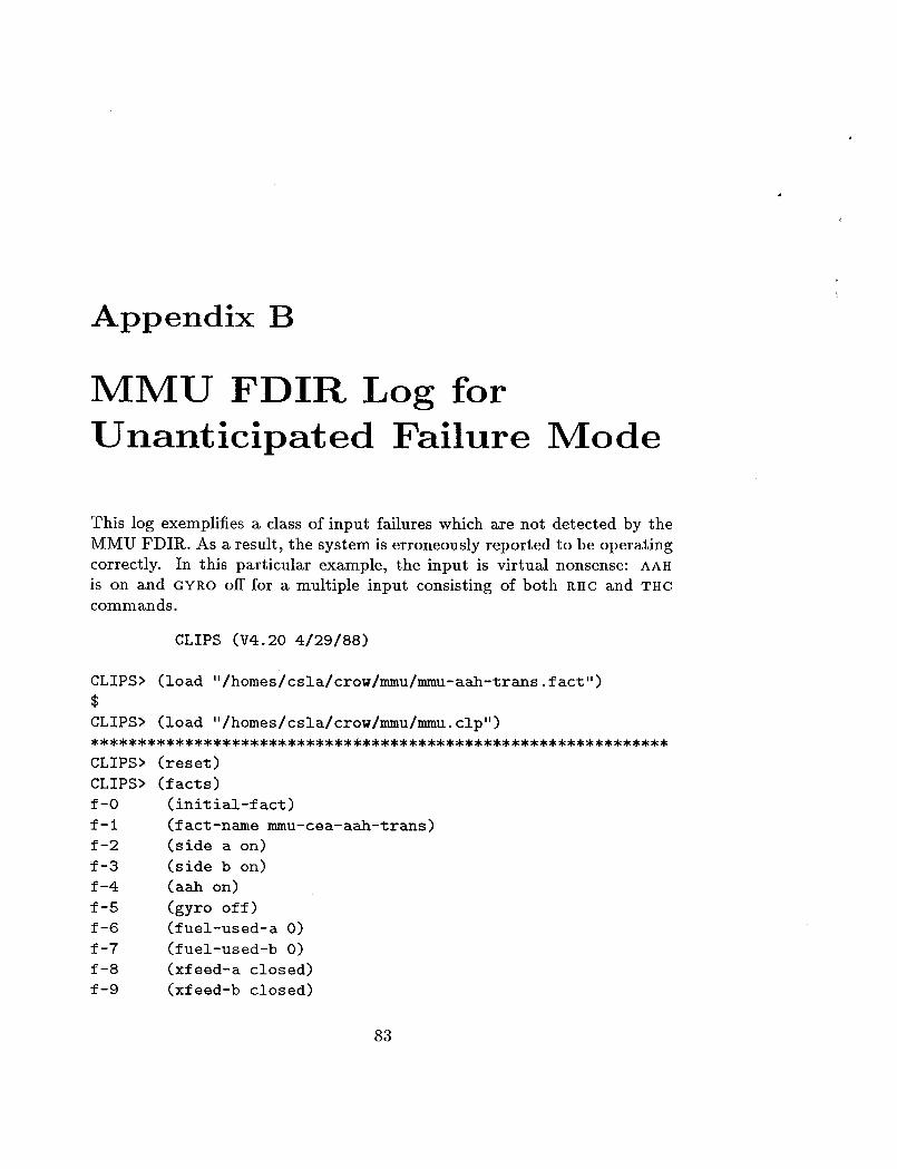
Appendix B
MMU FDIR Log for
Unanticipated Failure Mode
This log exemplifies a class of input failures which are not detected by the
MMU FDII_. As a result, the system is erroneously reported to be operating
correctly. In this particular example, the input is virtuM nonsense: AAH
is on and GYRO off for a multiple input consisting of both RHC and THC
commands.
CLIPS (V4.20 4/29/88)
CLIPS> (load "/homes/csla/crow/mmu/mmu-aah-trans. fact")
$
CLIPS> (load "/homes/csla/crow/mmu/mmu.clp")
CLIPS> (reset)
CLIPS> (facts)
f-O
f-1
f-2
f-3
f-4
f-5
f-6
f-7
f-8
f-9
(initial-fact)
(fact-namemmu-cea-aah-trans)
(side a on)
(side b on)
(aah on)
(gyro off)
(fuel-used-a 0)
(fuel-used-b 0)
(xfeed-a closed)
(xfeed-b closed)
83
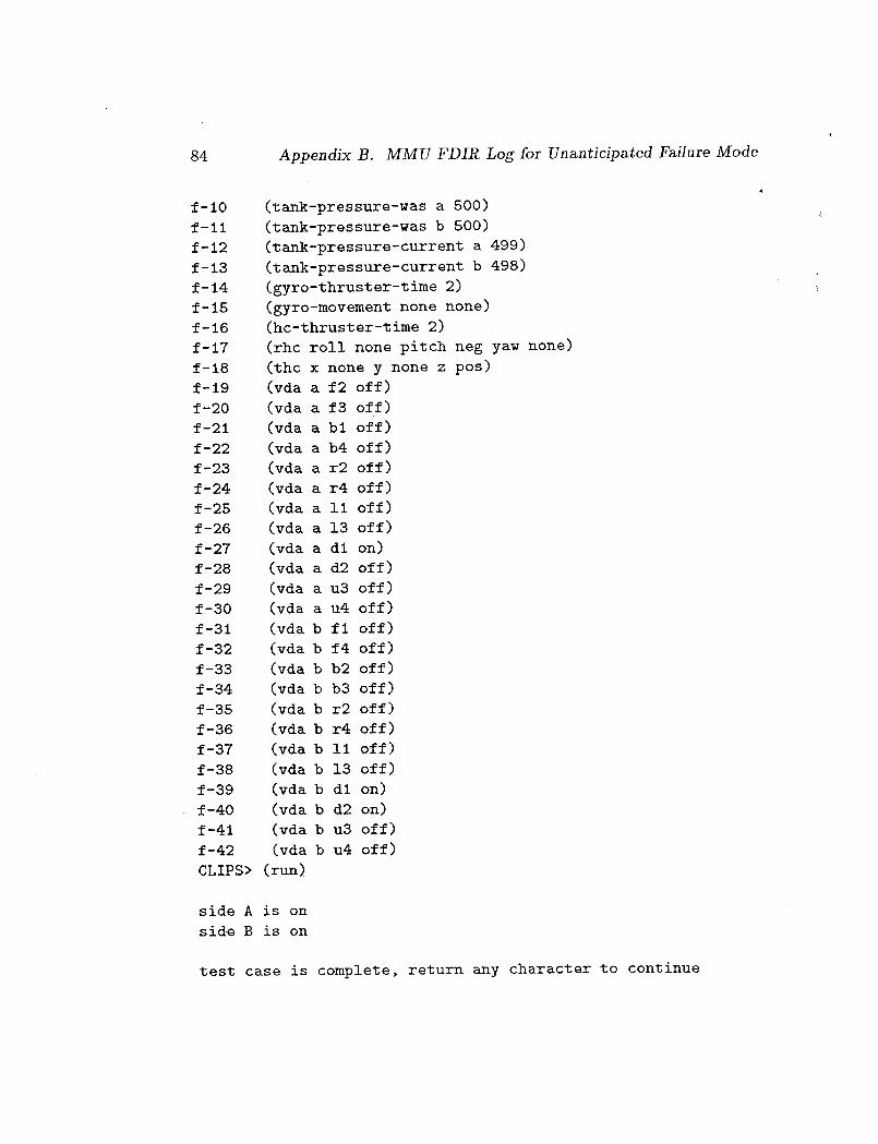
84 Appendix B. MMU FDIR Log for Unanticipated Failure Mode
f-lO
f-ll
f-12
f-13
f-14
f-15
f-16
f-17
f-18
f-19
f-20
f-21
f-22
f-23
f-24
f-25
f-26
f-27
f-28
f-29
f-30
f-31
f-32
f-33
f-34
f-35
f-36
f-37
f-38
f-39
f-40
f-41
f-42
(tank-pressure-was a 500)
(tank-pressure-was b 500)
(tank-pressure-current a 499)
(tank-pressure-current b 498)
(gyro-thruster-time 2)
(gyro-movement none none)
(hc-thruster-time 2)
(rhc roll none pitch neg yaw none)
(the x none y none z pos)
(vda a f2 off)
(vda a f3 off)
(vda a bl off)
(vda a b4 off)
(vda a r2 off)
(vda a r4 off)
(vda a ii off)
(vda a 13 off)
(vda a dl on)
(vda a d2 off)
(vda a u3 off)
(vda a u4 off)
(vda b fl off)
(vda b f4 off)
(vda b b2 off)
(vda b b3 off)
(vda b r2 off)
(vda b r4 off)
(vda b ii off)
(vda b 13 off)
(vda b dl on)
(vda b d2 on)
(vda b u3 off)
(vda b u4 off)
CLIPS> (run)
side A is on
side B is on
test case is complete, return any character to continue

q5 rules firedCLIPS>
85

Appendix C
A BASIC Implementation of
the MMU FDIR
The basic program in this appendix is included strictly as a proof of concept.
Although we have tested many of the control paths, all THC, RnC, and
GYRO input behaviors have not been verified. We have encoded the correct
thruster configurations for THC, RHC, and GYRO inputs procedurally (i.e.,
as subroutines) to reflect the design of the MMU FDIR, system. However,
it would clearly be preferable to recode this information in table form (i.e.,
as a BASIC array or set of arrays) and use generM table access mechanisms
for primary and backup mode tests.
20 REM Test first side primary, if ok test second side primary, if
either first or second side primary bad then test both sides in
backup, report recovery.
30 REM thruster configuration definitions
DIR is the direction (pos/neg) of the AXIS (pitch, yaw, etc.)
SIDE is one of A/B.
40 REM actual thruster configuration correct for given command?
50 REM TI, T2 are (possibly null) pairs of thruster configurations,
e.g., '!Fl F3". TI is the correct configuration, T2 the input
configuration.
6O DEF FNTHRUSTERSOK(TI$,T2$)=
(TI$=T2$) or
(LEFT$(TI$,2)=RIGHT$(T2$,2) AND RIGHT$(TI$,2)=LEFT$(T2$,2)
AND LEN(T2$)=5) 'note: t25 must be actual/input thrusters
86
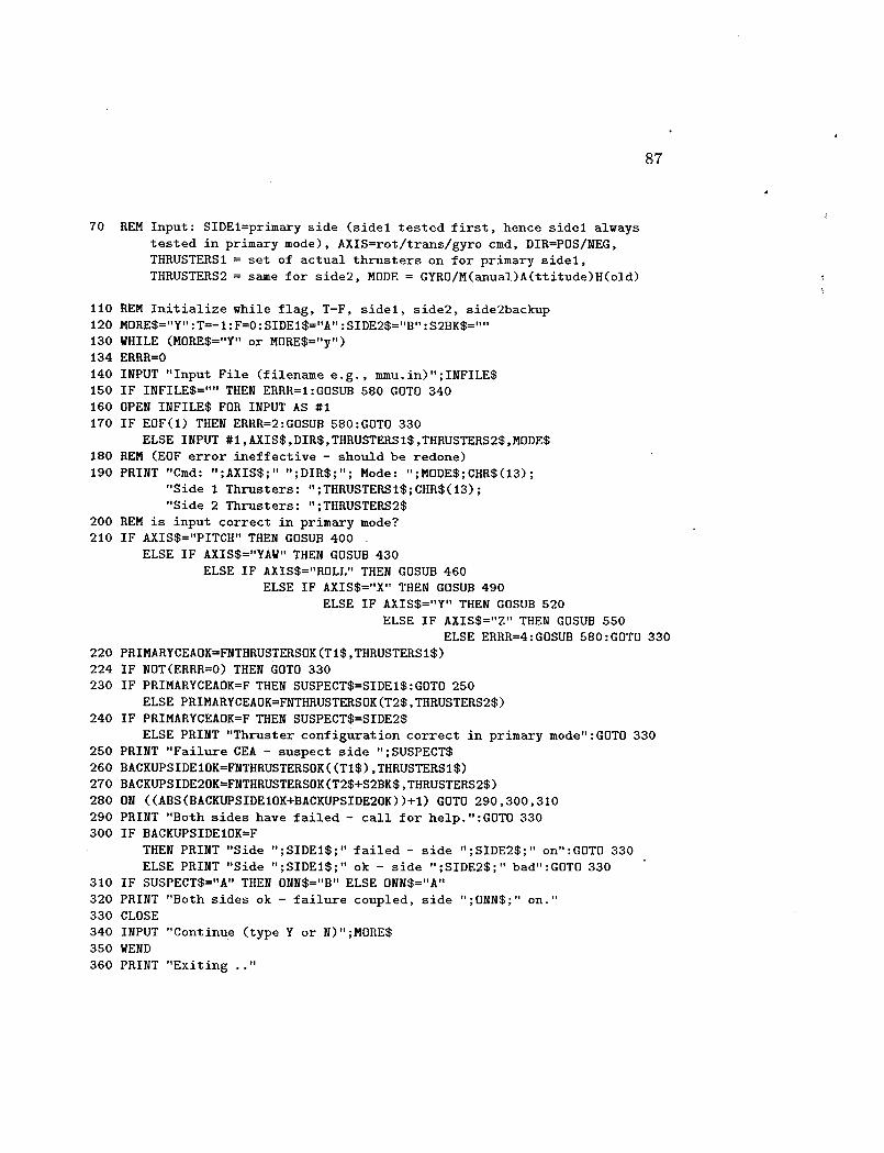
87
7O REM Input: SIDEl=primary side (sidel tested first, hence sidel always
tested in primary mode), AXIS=rot/trans/gyro cmd, DIR=POS/NEG,
THRUSTERS1 = set of actual thrusters on for primary sidel,
THRUSTERS2 = same for side2, MODE = GYRO/M(anual)A(ttitude)H(old)
110 REM Initialize while flag, T-F, sidel, side2, side2backup
120 MORES="Y":T=-I:F=O:SIDElS="A":SIDE2S="B":S2BKS=""
130 WHILE (MORES="Y" or MORES="y")
134 ERRR=O
140 INPUT "Input File (filename e.g., mmu.in)";INFILES
150 IF INFILES="" THEN ERRR=I:GOSUB 580 GOTO 340
160 OPEN INFILES FOR INPUT AS #I
170 IF EOF(1) THEN ERRR=2:GOSUB 580:GDTO 330
ELSE INPUT #1,AXISS,DIRS,THRUSTERSlS,THRUSTERS2S,MODES
180 REM (EOF error ineffective - should be redone)
190 PRINT "Cmd: ";AXISS;" ";DIRS;"; Mode: ";MODE$;CHRS(13);
"Side I _"nrusters: ";THRUSTERSIS;CHR@(13);
"Side 2 _"nrusters: ";THRUSTE_2$
200 REM is input correct in primary mode?
210 IF AXISS="PITCH" THEN GOSUB 400
ELSE IF AXISS="YAW" THEN GOSUB 430
ELSE IF AXISS="ROLL" THEN GOSUB 460
ELSE IF AXISS="X" THEN GOSUB 490
ELSE IF AXIS$="Y" THEN GOSUB 520
ELSE IF AXIS$="Z" THEN GOSUB 550
ELSE ERRR=4:GOSUB 580:GOTO 330
220 PRIMARYCEAOK=FNTHRUSTERSOK(TIS,THRUSTERSI$)
224 IF NOT(ERRR=O) THEN GOTO 330
230 IF PRIMARYCEAOK=F THEN SUSPECT$=SIDEIS:GOTO 250
ELSE PRIMARYCEAOK=FNTHRUSTERSOK(T2S,THRUSTERS2S)
240 IF PRIMARYCEAOK=F THEN SUSPECTS=SIDE2$
ELSE PRINT "_"nruster configuration correct in primary mode":GOTO 330
250 PRINT "Failure CEA - suspect side ";SUSPECTS
260 BACKUPSIDEIOK=FNTHRUSTERSOK((TIS),THRUSTERSI$)
270 BACKUPSIDE2OK=FNTHRUSTERSOK(T2S+S2BK$,THRUSTERS2S)
280 ON ((ABS(BACKD_SIDEIOK+BACKUPSIDE2OK))+I) GOTO 290,300,310
290 PRINT "Both sides have failed - call for help.":GOTO 330
300 IF BACKUPSIDEIOK=F
THEN PRINT "Side "; SIDEIS ;" failed - side " ;SIDE2$ ; " on" :GOTO 330
ELSE PRINT "Side ";SIDEI$;" ok - side ";SIDE2@; " bad":GOTO 330
310 IF SUSPECTS="A" THEN ONNS="B" ELSE ONNS="A"
320 PRINT "Both sides ok - failure coupled, side ";ONN$;" on."
330 CLOSE
340 INPUT "Continue (type Y or N)";MORES
350 WEND
360 PRINT "Exiting .."

88 Appendix C. A BASIC Implementation of the MMU FDIR
370 END
380 REM _subroutines'
390 REM PITCH subroutine (MAH=Manual auto hold - i.e., not GYRO)
400 IF DIR$="POS"
THEN IF MODE$="MAH"
THEN TI$="BI F3" :T25="" :S2BK$="B2 F4"
ELSE SIDEI$="B" :SIDE2$="A" :TI$="B3 FI" :T25="" :S2BK$="B4 F2"
ELSE IF MODE$="MAH"
THEN SIDEI$="B" :SIDE2$="A" :TI$="B3 FI" :T25="" :S2BK$="F2 B4"
ELSE TI$="BI F3" :T25 ='''':S2BK$="B2 F4"
410 RETURN
490 REM YAW subroutine
430 IF DIR$="POS"
THEN IF MODE$="MAH"
THEN TI$="BI F2" :T25="" :S2BK$="B3 F4"
ELSE SIDEI$="B" :SIDE2$="A" :TI$="B2 FI" :T25="" :S2BK$="B4 F3"
ELSE IF MODE$="MAH"
THEN SIDEI$="B" :SIDE2$="A" :TI$="B2 FI" :T25="" :S2BK$="F3 B4"
ELSE TI$="BI F2" :T2$="":S2BK$="H3 F4"
440 RETURN
450 REM ROLL subroutine
460 IF DIR$="POS"
THEN IF MODE$="MAH"
THEN TI$="R2 L3" :T2$="":S2BK$="R2 L3"
ELSE SIDE!$="B '':SIDE2$="A":TI$="LI R4" :T25="" :S2BK$="LI R4"
ELSE IF MODE$="MAH"
THEN SIDEI$="B" :SIDE2$="A" :TI$="R4 LI" :T25="" :S2BK$="R4 LI"
ELSE TI$="R2 L3":T2$="":S2BK$="R2 L3"
470 RETURN
480 REM X subroutine
490 IF MODE$="MAH"
THEN IF DIR$="POS"
THEN TI$="F2 F3":T2$="F1 F4":S2BK$=T2$
ELSE TI$="B1 B4":T25="B2 B3" :S2BK$=T2$
ELSE ERRR=3:GOSUB 580
500 RETURN
510 REM Y subroutine
520 IF MODE$="MAH"
THEN IF DIR$="POS"
THEN TI$="R2 R4" : T2$=TI$ : S2BK$=T2$
ELSE TI$="L1 L3" : T2$=TI$ : S2BK$=T2$
ELSE ERRR=3:GOSUB 580
530 RETURN
540 REM Z subroutine
550 IF MODE$="MAH"
THEN IF DIR$="POS ''
THEN TI$="D1 D2" :T2$=TI$:S2BK$=T2$
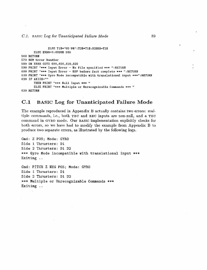
C.1. BASIC Log for Unanticipated Failure Mode
ELSE TI$="U3 U4":T2$=TI$:S2BK$=T2$
ELSE ERRR=3:GOSUB 580
560 RETURN
570 REM Error Handler
580 ON ERBR GOTO 590,600,610,620
590 PRINT "*** Input Error - No file specified *** ":RETURN
600 PRINT "*** Input Error - EOF before fact complete *** ":RETURN
6i0 PRINT "*** Gyro Mode incompatible with translational input ***":RETURN620 IF AXIS$=""
THEN PRINT "*** Null Input *** "
ELSE PRINT "*** Multiple or Unrecognizable Commands *** "630 RETURN
89
C.1 BASIC Log for Unanticipated Failure Mode
The example reproduced in Appendix B actually contains two errors: mul-
tiple commands, i.e., both T_C and RHC inputs are non-null, and a THc
command in GYRO mode. Our BASIC implementation explicitly checks for
both errors, so we have had to modify the example from Appendix B to
produce two separate errors, as illustrated by the following logs.
Cmd: Z POS; Mode: GYRO
Side I Thrusters: DI
Side 2 Thrusters: D1 D2
*** Gyro Mode incompatible with translational input ***
Exiting ..
Cmd: PITCH Z NEG POS; Mode: GYRO
Side I Thrusters: DI
Side 2 Thrusters: D1 D2
*** Multiple or Unrecognizable Commands ***
Exiting ..

Bibliography
[1]
[2]
[3]
[4]
[s]
[6]
[7]
Is]
Kathy H. Abbott. Robust operative diagnosis as problem solving in a
hypothesis space. In Proceedings, AAAI 88 (Volume 1), pages 369-374,
Saint Paul, MN., August 1988.
CLIPS Reference Manual. Artificial Intelligence Center, Lyndon B.
Johnson Space Center, July 1989. Version 4.3 of CLIPS.
L. Brownston, R. Farrell, E. Kant, and N. Martin. Programming Expert
Systems in OPS5. Addison-Wesley, Reading, MA, 1985.
Bruce G. Buchanan and Reid G. Smith. Fundamentals of expert sys-
tems. In Joseph F. Traub, Barbara J. Grosz, Butler W. Lampson, and
Nils J. Nilsson, editors, Annual Review of Computer Science, Volume
3, pages 23-58. Annual Reviews, Inc., Palo Alto, CA., 1988.
B. Chandraskeran and W.F. Punch III. Data validation during diagno-
sis, a step beyond traditional sensor validation. In Proceedings, AAAI
87 (Volume 2), pages 778-782, Seattle, WA, July 1987.
Chin Chang and Rolf Stachowitz. Testing expert systems. In Pro-
ceedings of the Space Operations Automation and Robotics (SOAR-88)
Workshop, 1988. Dayton, OH.
Christine Chee and Margaret Power. Expert systems maintainability.
In Proceedings of the Annual Reliability and Maintainability Sympo-
sium, 1990. IEEE.
William J. Clancey. The advantages of abstract control knowledge in
expert system design. In Proceedings of the National Conference on
AI(AAAI-83), 1983. Washington, DC.
9O
Bibliography 91
[9] Lori Clarke, Andy Podgurski, Debra Richardson, and Steven Zeil. A
formal evaluation of data flow path selection criteria. IEEE Transac-
tions on Software Engineering, 15(11):1318-1332, November 1989.
[10] Craig Covalt. Cosmonauts fly maneuvering unit while tethered to
Mir space station. Aviation Week and Space Technology, pages 29-30,
February 12, 1990.
[11] Randall Davis and Walter Hamscher. Model-based reasoning: Trou-
bleshooting. In Howard E. Shrobe, editor, Exploring Artificial Intelli-
gence: Survey Talks from the National Conferences on Artificial Intel-
ligence, chapter 8, pages 297-346. Morgan Kaufmann Publishers, Inc,
San Mateo, CA., 1988.
[12] Joe W. Duran and Simeon C. Ntafos. An evaluation of random testing.
IEEE Transactions on Software Engineering, SE-10(4):438-443, April
1984.
[13] Michael P. Georgeff. Planning. In Joseph F. Traub, Barbara J. Grosz,
Butler W. Lampson, and Nils J. Nilsson, editors, Annual Review of
Computer Science, Volume 2, pages 359-400. Annum Reviews, Inc.,
Palo Alto, CA., 1987.
[14] Michael P. Georgeff and Francois F_lix Ingrand. Decision-making in an
embedded reasoning system. In Proceedings, 11th IJCAI, pages 972-
978, Detroit, MI, August 1989.
[15] Michael P. Georgeff and Fran§ois F_lix Ingrand. Real-time reasoning:
The monitoring and control of spacecraft systems. In Proceedings of the
Sixth Conference on Artificial Intelligence Applications, pages 198-204,
Santa Barbara, CA, March 1990. IEEE Computer Society.
[16] Michael P. Georgeff and Amy Y. Lansky. Procedural knowledge. Pro-
ceedings of the IEEE, 74(10):1383-1398, October 1986.
[17] Joseph Giarratano. CLIPS User's Guide. Artificial Intelligence Sec-
tion, 3ohnson Space Center, August 1989. Version 4.3 of CLIPS.
[18] Joseph Giarratano and Gary Riley. Expert Systems: Principles and
Programming. PWS-Kent Publishing Company, Boston, MA, 1989.
[19] D.C. Ince. The automatic generation of test data. Computer Journal,
30(1):63-69, February 1987.
92 Bibliography
[20] D.C. Ince and S. Hekmatpour. An empirical evaluation of random
testing. Computer Journal, 29(4):380, August 1986.
[21]Robert J.K. Jacob and Judith N. Froscher. Developing a software en-
gineering methodology for knowledge-based systems. Technical Report
9019, Naval Research Laboratory, Washington, D.C., December 1986.
[22] James Kiper. Structural testing of rule-based expert systems. In Pre-
liminary Proceedings IJCAI-89 Workshop on Verification, Validation
and Testing of Knowledge-Based Systems, 1989. Detroit, MI.
[23] D.E. Knuth and P.B. Bendix. Simple word problems in universal alge-
bras. In J. Leech, editor, Computational Problems in Abstract Algebra,
pages 263-293. Pergamon, New York, NY., 1970.
[24] Dennis G. Lawler and Linda J.F. Williams. MMU FDIR automation
task. Final report, McDonnell Douglas Astronautics Company, 16055
Space Center Blvd., Houston, TX 77062, February 1988.
[25] 3. Lloyd. Foundations of Logic Programming. Springer-Verlag, Berlin,
West Germany, 1984.
[26] C.K. Mohan. Priority rewriting: semantics, confluence, and condition-
als. In Proceedings of the Third International Conference on Rewriting
Techniques and Applications, pages 278-291, Chapel Hill, NC, 1989.
[27] MMU Systems Data Book. NASA MMU-SE-17-73, revision: basic edi-
tion, June 1983. Volume 1 of MMU Operational Data Book.
[28] Simeon Ntafos. On required element testing. IEEE Transactions on
Software Engineering, SE-10(6):795-803, November 1984.
[29] Thomas J. Ostrand and Marc J. Balcer. The category-partition method
for specifying and generating functional tests. Communications of the
ACM, 31(6):676-686, June 1988.
[30] David Lorge Parnas. Why engineers should not use Artificial Intelli-
gence. INFOR, 26(4):234-245, January 1988.
C.V. Ramamoorthy, Shashi Shekhar, and Vijay Garg. Software de-
velopment support for AI programs. IEEE Computer, 20(1):30-40,
January 1987.

Bib_ography 93
[32]
[33]
[34]
[35]
[36]
[37]
[38]
[39]
[4o]
Sandra Rapps and Elaine J. Weyuker. Selecting software test data using
data flow information. IEEE Transactions on Software Engineering,
SE-11(4):367-375, April 1985.
Raymond Reiter. A theory of diagnosis from first principles. Artificial
Intelligence, 32:57-95, 1987.
John Rushby. Quality measures and assurance for AI software. Con-
tractor report 4187, NASA, October 1988.
John R.ushby and 1_. Alan Whitehurst. Formal verification of AI soft-
ware. Contractor report 181827, NASA, Langley Research Center,
Hampton, VA, February 1989.
Ethan A. Scarl, John R.. Jamieson, and Carl I. Delaune. Diagnosis and
sensor validation through knowledge of structure and function. IEEE
Transactions on Systems, Man, and Cybernetics, SMC-17(3):360-368,
May/June 1987.
Paul C. Schutte and Kathy H. Abbott. An artificial intelligence ap-
proach to onboard fault monitoring and diagnosis for aircraft appli-
cations. In Proceedings, AIAA Guidance and Control Conference,
Williamsburg, VA., August 1986.
Roll Stachowitz, Jacqueline Combs, and Chin Chang. Valida-
tion of knowledge-based systems. In Proceedings of the Second
AIAA/NASA/USAF Symposium on Automation, Robotics and Ad-
vanced Computing for the National Space Program, 1987. Arlington,VA.
S.A. Vere. Relational production systems. Artificial Intelligence,
8(1):47-68, February 1977.
Elaine J. Weyuker and Thomas J. Ostrand. Theories of program testing
and the application of revealing subdomains. IEEE Transactions on
Software Engineering, SE-6(3):236-246, May 1980.

Report Documentation Page_110".34 _r_C_ulIC5 and
1. Report No.
NASA CR-187466
2. Government Accession No.
4. Title and Subtitle
Evaluation of an Expert System for Fault Detection,
Isolation, and Recovery in the Manned Maneuvering
Unit
7. Author(s)
John Rushby and Judith Crow
9. Pe_orming Organization Name and Address
SRI International
333 Ravenswood Avenue
Menlo Park, CA 94025
12. Sponsoring Agency Name and Address
National Aeronautics and Space Administration
Langley Research Center
Hampton, VA 23665-5225
3. Recipient's Catalog No.
5. Report Date
December 1990.,
6. Performing Organization Code
8, Performing Organization Report No:
10. Work Unit No.
488-80-04-01
11. Contract or Grant No.
NASI-18226
13. Type of Report and Period Covered
Contractor Report
14. Sponsoring Agency Code
15. Supplementa_ Notes
Technical Monitor:
Task 9 Final Report
Sally C. Johnson, Langley Research Center
16. Ab_ract
We explore issues in the specification, verification, and validation of AI-based
software using a prototype Fault Detection, Isolation, and Recovery (FDIR)
system for the Manned-Maneuvering Unit (MMU). We use this system, which is
implemented in CLIPS, as a vehicle for exploring issues in the semantics of
CLiPS-style, rule-based languages, the verification of properties relating to
safety and reliability, and the static and dynamic analysis of knowledge-based
systems. Our analysis reveals errors and shortcomings in the MMU FDIR system
and raises a number of issues concerning software engineering in CLIPS.
In the course of this work we came to realize that the MMU FDIR system does not
conform to conventional definitions of AI software, despite the fact that it
was intended and indeedpresented as an AI system. We discuss this apparent
disparity and related questions such as the role of AI techniques in space and
aircraft operations and the suitability of CLIPS for critical applications.
17. Key Words (Suggested by Author(s))
Artificial Intelligence
Expert Systems
Validation
Verification
19. SecuriW Cla=if. (of this repot)
Unclassified
NASA FORM 1626 OCT 86
18. Distribution Statement
Unclassified - Unlimited
Subject Category 61
SecuriW Cla_if. (of this page)
Unclassified
21. No. of pages
102
22. Price
A06