n smith s pltw engineering design gt midterm...
TRANSCRIPT
N Smith’s PLTW Engineering Design GT – Midterm Exam Total Test Items: 90 questions (3 sections with 30 questions per section)
Material allowed during test: PLTW formula sheet & calculator
Contents Unit 1 Design Process - Overview ..................................................................................................................................... 2
Unit 2 Technical Sketching and Drawing - Overview ...................................................................................................... 8
Unit 3 Measurement and Statistics - Overview .............................................................................................................. 14
Unit 4 Modeling Skills - Overview .................................................................................................................................... 23
Unit 5 Geometry of Design - Overview ........................................................................................................................... 29

Unit 1 Design Process - Overview
Preface
Each time that you solve a problem, a design process is used. Some processes are as simple as realizing that you are hungry
for something new and then designing a new combination of foods. Process can be as complex as designing a clean water
solution for a village in an emerging nation. The design process (i.e., method to solve a problem or create a new product) is a
cornerstone of all engineering professions.
This lesson provides a foundation for engineering knowledge and professional practices that will be used through this and
other pathway to engineering courses and throughout a student’s career. Students will develop skills such as concept
sketching, setting up, and maintaining an engineering notebook and portfolio.
Engineering is a professional practice that has evolved through centuries of experience. Learning concepts and practicing
skills in this course will provide a foundation for a lifelong engineering career.
Understandings, Knowledge and Skills
Understandings Knowledge and Skills
An engineering design process
involves a characteristic set of
practices and steps.
Identify and define the terminology used in engineering design and
development.
Identify the steps in an engineering design process and summarize the
activities involved in each step of the process.
Complete a design project utilizing all steps of a design process, and find a
solution that meets specific design requirements.
Research derived from a variety of
sources (including subject matter
experts) is used to facilitate
effective development and
evaluation of a design problem and
a successful solution to the
problem.
Utilize research tools and resources (such as the Internet; media centers;
market research; professional journals; printed, electronic, and multimedia
resources; etc.) to gather and interpret information to develop an effective
design brief.
A problem and the requirements for
a successful solution to the
problem should be clearly
communicated and justified.
Define and justify a design problem, and express the concerns, needs, and
desires of the primary stakeholders.
Present and justify design specifications, and clearly explain the criteria and
constraints associated with a successful design solution.
Write a design brief to communicate the problem, problem constraints, and
solution criteria.
Brainstorming may take many
forms and is used to generate a
large number of innovative,
creative ideas in a short time.
Generate and document multiple ideas or solution paths to a problem through
brainstorming.
A solution path is selected and
justified by evaluating and
comparing competing design
Clearly justify and validate a selected solution path.

solutions based on jointly
developed and agreed-upon design
criteria and constraints.
Physical models are created to
represent and evaluate possible
solutions using prototyping
technique(s) chosen based on the
presentation and/or testing
requirements of a potential
solution.
Construct a testable prototype of a problem solution.
Problem solutions are optimized
through evaluation and reflection
and should be clearly
communicated.
Describe the design process used in the solution of a particular problem and
reflect on all steps of the design process.
Justify and validate a problem solution.
Identify limitations in the design process and the problem solution and
recommend possible improvements or caveats.
The scientific method guides the
testing and evaluation of prototypes
of a problem solution.
Analyze the performance of a design during testing and judge the solution as
viable or non-viable with respect to meeting the design requirements.
Geometric shapes and forms are
described and differentiated by
their characteristic features.
Explain the concept of proportion and how it relates to freehand sketching.
Hand sketching of multiple
representations to fully and
accurately detail simple objects or
parts of objects is a technique used
to convey visual and technical
information about an object.
Generate non-technical concept sketches to represent objects or convey
design ideas.
Technical professionals clearly and
accurately document and report
their work using technical writing
practice in multiple forms.
Organize and express thoughts and information in a clear and concise manner.
Adjust voice and writing style to align with audience and purpose.
Support design ideas using a variety of convincing evidence.
Utilize an engineering notebook to clearly and accurately document the design
process according to accepted standards and protocols to prove the origin and
chronology of a design.
Document information sources using appropriate formats.
Specific oral communication
techniques are used to effectively
convey information and
communicate with an audience.
Deliver organized oral presentations of work tailored to the audience.
Establish objectives for the presentation that are appropriate for the audience.
Facilitate engaging and purposeful dialog with the audience.
Sketches, drawings, and images
are used to record and convey
specific types of information
depending upon the audience and
the purpose of the communication.
Create drawings or diagrams as representations of objects, ideas, events, or
systems.
Select and utilize technology (software and hardware) to create high impact
visual aids.

Use presentation software effectively to support oral presentations.
Engineering has a global impact on
society and the environment.
Define and differentiate invention and innovation.
Assess the development of an engineered product and discuss its impact on
society and the environment.
Identify and discuss a Grand Challenge for Engineering (as identified by the
National Academy of Engineering) and its potential impact on society and the
environment.
Engineering consists of a variety of
specialist sub-fields, with each
contributing in different ways to the
design and development of
solutions to different types of
problems.
Identify and differentiate between mechanical, electrical, civil, and chemical
engineering fields.
Describe the contributions of engineers from different engineering fields in the
design and development of a product, system, or technology.
Differentiate between the work of an engineer and the work of a scientist.
In order to be an effective team
member, one must demonstrate
positive team behaviors and act
according to accepted norms,
contribute to group goals according
to assigned roles, and use
appropriate conflict resolution
strategies.
Demonstrate positive team behaviors and contribute to a positive team
dynamic.
Essential Questions (Unit-Specific)
1. How might we create the best possible solution to a problem?
2. What is the most effective way to generate potential solutions to a problem? How many alternate solutions should
you generate?
3. What are the most pressing engineering/technical problems of our time?
4. What is an engineer? What types of work do engineers do?
Key Term Definition
Assess To thoroughly and methodically analyze accomplishment against specific goals and criteria.
Assessment
An evaluation technique for technology that requires analyzing benefits and risks,
understanding the trade-offs, and then determining the best action to take in order to ensure
that the desired positive outcomes outweigh the negative consequences.
Techniques used to analyze accomplishments against specific goals and criteria. Examples of
assessments include tests, surveys, observations, and self-assessment.
Brainstorm
A group technique for solving problems, generating ideas, stimulating creative thinking, etc.
by unrestrained spontaneous participation in discussion.
Client
A person using the services of a professional person or organization.
Creativity The ability to make or bring a new concept or idea into existence; marked by the ability or
power to create.
Criteria A means of judging. A standard, rule, or test by which something can be judged.
Constraint
1. A limit to a design process. Constraints may be such things as appearance, funding, space,
materials, and human capabilities. 2. A limitation or restriction.

Design
1. An iterative decision-making process that produces plans by which resources are converted
into products or systems that meet human needs and wants or solve problems. 2. A plan or
drawing produced to show the look and function or workings of something before it is built or
made. 3. A decorative pattern.
Design Brief
A written plan that identifies a problem to be solved, its criteria, and its constraints. The
design brief is used to encourage thinking of all aspects of a problem before attempting a
solution.
Design Process
A systematic problem-solving strategy, with criteria and constraints, used to develop many
possible solutions to solve a problem or satisfy human needs and wants and to winnow
(narrow) down the possible solutions to one final choice.
Design
Statement A part of a design brief that challenges the designer, describes what a design solution should
do without describing how to solve the problem, and identifies the degree to which the
solution must be executed.
Designer
A person who designs any of a variety of things. This usually implies the task of creating
drawings or in some ways uses visual cues to organize his or her work.
Engineer
A person who is trained in and uses technological and scientific knowledge to solve practical
problems.
Engineering
Notebook
A book in which an engineer will formally document, in chronological order, all of his/her
work that is associated with a specific design project.
Innovation
An improvement of an existing technological product, system, or method of doing something.
Invention
A new product, system, or process that has never existed before, created by study and
experimentation.
Iterative A process that repeats a series of steps over and over until the desired outcome is obtained.
Justifiable Capable of being shown as reasonable or merited according to accepted standards.
Piling-on An idea that produces a similar idea or an enhanced idea.
Problem
Identification The recognition of an unwelcome or harmful matter needing to be dealt with.
Product
A tangible artifact produced by means of either human or mechanical work, or by biological
or chemical process.
Prototype A full-scale working model used to test a design concept by making actual observations and
necessary adjustments.
Research
The systematic study of materials and sources in order to establish facts and reach new
conclusions.
Valid Well-founded on evidence and corresponds accurately to the real world.
1.3 Engineering Notebook –
A. formally document, in chronological order, all of his/her work that is associated with a specific design project
B. Someone unfamiliar with work could take over project without additional information C. recognized as a legal document that is used in patent activities

D. CONTENTS E. SECTIONS
a. Title Page b. Table of Contents c. General Chronological Entries d. References e. Business/Expert Contacts
1.4 Brainstorming
1.5 Design Process A design process is a systematic problem-solving strategy, with criteria and constraints,
used to develop many possible solutions to solve or satisfy human needs or wants and to narrow down the
possible solutions to one final choice.
1 Define the Problem :
Identify a problem
Validate the problem
Who says it is a problem?
Needs and wants
Prior solutions
Justify the problem
Is the problem worth solving?
Create design requirements (specifications)

Criteria and constraints
Design Brief (Client / End User / Target Consumer, Problem Statement, Design
Statement, Constraints)
2. Generate Concepts:
Research
Brainstorm possible solutions
Consider additional design goals
Apply STEM principles
Select an approach
Decision Matrix
3. Develop a Solution
Create detailed design solution
Justify the solution path
Technical Drawings
4. Construct and Test Prototype
Construct a testable prototype
Plan prototype testing
Performance
Usability
Durability
Test prototype
collect test data
analyze test data
Test Report
5. Evaluate the solution
Evaluate solution effectiveness
Reflect on design
Recommend improvements
Optimize/Redesign the solution
[Return to prior design process steps, if necessary]
Revise design documents
Project Recommendations
6. Present the Solution
Document the project Project Portfolio
Communicate the project Formal Presentation
1.6 Engineering Disciplines
• ENGINEERS – Research, Develop, Design, Supervise, Manage
– Chemical
– New fuels for rockets, reactors, and booster propulsion
– Medicines, vaccines, serum, and plasma
– Plastics, synthetics and textiles
– Civil
Space satellites Launch facilities
Offshore structures Bridges
Buildings Highways
Transit systems Dams
Airports Irrigation projects
Collection and treatment for
wastewater
Treatment and distribution facilities
for water
Tunnels
– Electrical
– Large electrical systems
– Motors and generators
– Electrical circuits in Buildings
– Power transmission systems
– Electrical generation plants
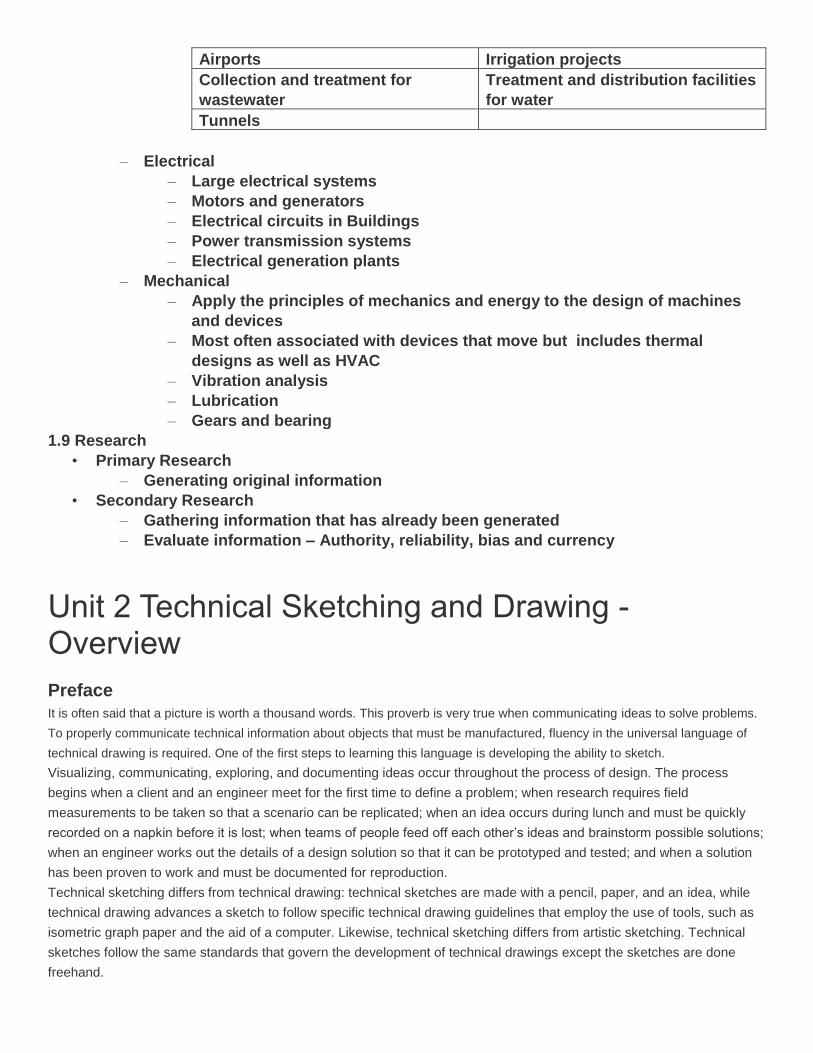
– Mechanical
– Apply the principles of mechanics and energy to the design of machines
and devices
– Most often associated with devices that move but includes thermal
designs as well as HVAC
– Vibration analysis
– Lubrication
– Gears and bearing
1.9 Research
• Primary Research
– Generating original information
• Secondary Research
– Gathering information that has already been generated
– Evaluate information – Authority, reliability, bias and currency
Unit 2 Technical Sketching and Drawing - Overview
Preface
It is often said that a picture is worth a thousand words. This proverb is very true when communicating ideas to solve problems.
To properly communicate technical information about objects that must be manufactured, fluency in the universal language of
technical drawing is required. One of the first steps to learning this language is developing the ability to sketch.
Visualizing, communicating, exploring, and documenting ideas occur throughout the process of design. The process
begins when a client and an engineer meet for the first time to define a problem; when research requires field
measurements to be taken so that a scenario can be replicated; when an idea occurs during lunch and must be quickly
recorded on a napkin before it is lost; when teams of people feed off each other’s ideas and brainstorm possible solutions;
when an engineer works out the details of a design solution so that it can be prototyped and tested; and when a solution
has been proven to work and must be documented for reproduction.
Technical sketching differs from technical drawing: technical sketches are made with a pencil, paper, and an idea, while
technical drawing advances a sketch to follow specific technical drawing guidelines that employ the use of tools, such as
isometric graph paper and the aid of a computer. Likewise, technical sketching differs from artistic sketching. Technical
sketches follow the same standards that govern the development of technical drawings except the sketches are done
freehand.

As they advance in their experiences and skills through the course, students will learn basic rules of technical sketching in
this lesson and will learn the drawing standards that apply. The understanding of technical sketching is critical for
designers when effectively conveying their ideas about a product. Sketching is the beginning stage of product
development. Students will learn how to sketch isometric, oblique, perspective, and multi-view sketches of various
objects.
Understandings, Knowledge and Skills
Understandings Knowledge and Skills
Brainstorming may take many forms
and is used to generate a large
number of innovative, creative ideas
in a short time.
Generate and document multiple ideas or solution paths to a problem through
brainstorming.
Two- and three-dimensional objects
share visual relationships which allow
interpretation of one perspective from
the other.
Identify flat patterns (nets) that fold into geometric solid forms.
Geometric shapes and forms are
described and differentiated by their
characteristic features.
Explain the concept of proportion and how it relates to freehand sketching.
The style of the engineering graphics
and the type of drawing views used
to detail an object vary depending
upon the intended use of the graphic.
Identify and define technical drawing representations including isometric,
orthographic projection, oblique, perspective, auxiliary, and section views.
Identify the proper use of each technical drawing representation including
isometric, orthographic projection, oblique, perspective, auxiliary, and section
views.
Technical drawings convey
information according to an
established set of drawing practices
which allow for detailed and universal
interpretation of the drawing.
Identify line types (including construction lines, object lines, hidden lines,
cutting plane lines, section lines, and center lines) used on a technical
drawing per ANSI Line Conventions and Lettering Y14.2M-2008 and explain
the purpose of each line.
Determine the minimum number and types of views necessary to fully detail a
part.
Choose and justify the choice for the best orthographic projection of an object
to use as a front view on technical drawings.
Apply tonal shading to enhance the appearance of a pictorial sketch and
create a more realistic appearance of a sketched object.
Hand sketching of multiple
representations to fully and
accurately detail simple objects or
parts of objects is a technique used
to convey visual and technical
information about an object.
Hand sketch 1-point and 2-point perspective pictorial views of a simple object
or part given the object, a detailed verbal description or the object, a pictorial
view of the object, and/or a set of orthographic projections.
Hand sketch isometric views of a simple object or part at a given scale using
the actual object, a detailed verbal description of the object, a pictorial view of
the object, or a set of orthographic projections.
Hand sketch orthographic projections at a given scale and in the correct
orientation to fully detail an object or part using the actual object, a detailed
verbal description of the object, or a pictorial an isometric view of the object.
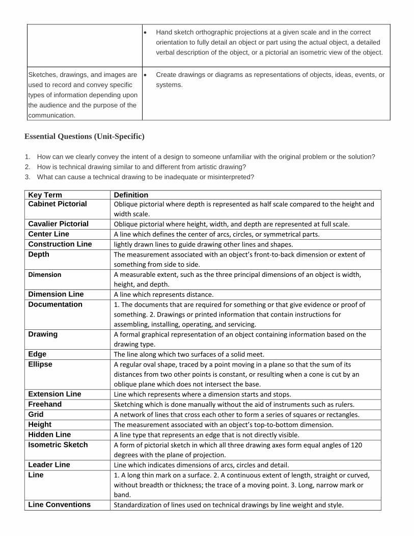
Sketches, drawings, and images are
used to record and convey specific
types of information depending upon
the audience and the purpose of the
communication.
Create drawings or diagrams as representations of objects, ideas, events, or
systems.
Essential Questions (Unit-Specific)
1. How can we clearly convey the intent of a design to someone unfamiliar with the original problem or the solution?
2. How is technical drawing similar to and different from artistic drawing?
3. What can cause a technical drawing to be inadequate or misinterpreted?
Key Term Definition
Cabinet Pictorial Oblique pictorial where depth is represented as half scale compared to the height and
width scale.
Cavalier Pictorial Oblique pictorial where height, width, and depth are represented at full scale.
Center Line A line which defines the center of arcs, circles, or symmetrical parts.
Construction Line lightly drawn lines to guide drawing other lines and shapes.
Depth The measurement associated with an object’s front-to-back dimension or extent of
something from side to side.
Dimension A measurable extent, such as the three principal dimensions of an object is width,
height, and depth.
Dimension Line A line which represents distance.
Documentation 1. The documents that are required for something or that give evidence or proof of
something. 2. Drawings or printed information that contain instructions for
assembling, installing, operating, and servicing.
Drawing A formal graphical representation of an object containing information based on the
drawing type.
Edge The line along which two surfaces of a solid meet.
Ellipse
A regular oval shape, traced by a point moving in a plane so that the sum of its
distances from two other points is constant, or resulting when a cone is cut by an
oblique plane which does not intersect the base.
Extension Line Line which represents where a dimension starts and stops.
Freehand Sketching which is done manually without the aid of instruments such as rulers.
Grid A network of lines that cross each other to form a series of squares or rectangles.
Height The measurement associated with an object’s top-to-bottom dimension.
Hidden Line A line type that represents an edge that is not directly visible.
Isometric Sketch A form of pictorial sketch in which all three drawing axes form equal angles of 120
degrees with the plane of projection.
Leader Line Line which indicates dimensions of arcs, circles and detail.
Line 1. A long thin mark on a surface. 2. A continuous extent of length, straight or curved,
without breadth or thickness; the trace of a moving point. 3. Long, narrow mark or
band.
Line Conventions Standardization of lines used on technical drawings by line weight and style.

Line Weight Also called line width. The thickness of a line, characterized as thick or thin.
Long-Break Line A line which indicates that a very long objects with uniform detail is drawn
foreshortened.
Manufacture To make something, especially on a large scale using machinery.
Measurement The process of using dimensions, quantity, or capacity by comparison with a standard
in order to mark off, apportion, lay out, or establish dimensions.
Multi-View Drawing A drawing which contains views of an object projected onto two or more orthographic
planes.
Object Line A heavy solid line used on a drawing to represent the outline of an object.
Oblique Sketch A form of pictorial in which an object is represented as true width and height, but
the depth can be any size and drawn at any angle.
Orthographic
Projection
A method of representing three-dimensional objects on a plane having only length and
breadth. Also referred to as Right Angle Projection.
Perspective Sketch
A form of pictorial sketch in which vanishing points are used to provide the depth and
distortion that is seen with the human eye.
Pictorial Sketch A sketch that shows an object’s height, width, and depth in a single view.
Plane A flat surface on which a straight line joining any two points would wholly lie.
Point A location in space.
Profile An outline of an object when viewed from one side.
Projection Line An imaginary line that is used to locate or project the corners, edges, and features of a
three-dimensional object onto an imaginary two-dimensional surface.
Projection Plane An imaginary surface between the object and the observer on which the view of the
object is projected and drawn.
Proportion 1. The relationship of one thing to another in size, amount, etc. 2. Size or weight
relationships among structures or among elements in a single structure.
Scale
1. A straight-edged strip of rigid material marked at regular intervals that is used to
measure distances. 2. A proportion between two sets of dimensions used to develop
accurate, larger or smaller prototypes, or models.
Section Lines Thin lines used in a section view to indicate where the cutting plane line has cut
through material.
Shading The representation of light and shade on a sketch or map.
Short-Break Line Line which shows where part is broken to reveal detail behind the part or to shorten a
long continuous part.
Shape A two-dimensional contour that characterizes an object or area, in contrast to three-
dimensional form.
Sketch A rough representation of the main features of an object or scene and often made as a
preliminary study.
Solid A three-dimensional body or geometric figure.
Technical Working
Drawing A drawing that is used to show the material, size, and shape of a product for
manufacturing purposes.
Three-Dimensional Having the dimensions of height, width, and depth.
Tone The general effect of color or of light and shade in a picture.
Two-Dimensional Having the dimensions of height and width, height and depth, or width and depth
only.
Vanishing Point A vanishing point is a point in space, usually located on the horizon, where parallel
edges of an object appear to converge.
View Colloquial term for views of an object projected onto two or more orthographic planes
in a multi-view drawing.

Width The measurement associated with an object’s side-to-side dimension.
2.1 Line conventions –
Precedence of Lines
• Complex object sketches may require different line types to overlap • Line precedence must be used • Rules that govern line precedence in sketches and technical drawings
– Object lines take precedence over hidden and center lines – Hidden lines take precedence over center lines – Cutting plane lines take precedence over all others
2.1 Pictorials • 2D illustration of a 3D object • Shows three faces of an object in one view • Provides a realistic view of an object • Three types:
Isometric
Isometric means equal measure.
Three adjacent faces on a cube will share a single point
Oblique (cavalier & cabinet)
An Oblique pictorial starts with a straight-on view of one of the object’s faces, which is often the front face
Perspective most realistic three-dimensional view

•
•
•
• • Multi-view or Orthographic
• Shows two or more two-dimensional views of a three-dimensional object. • Provides the shape description of an object. • When combined with dimensions, serves as the main form of communication between
designers and manufacturers. • how to select the front view
• Most natural position or use • Shows best shape and characteristic contours • Longest dimensions • Fewest hidden lines • Most stable and natural position
• Orthographic projections share common dimensions • A 45 degree mitre line can be used with construction lines to share information between right and top
views

•
Unit 3 Measurement and Statistics - Overview
Preface
The practice of measuring is older than recorded history. Every human civilization throughout history developed its own
measuring tools and, along with them, its own measuring standards. It was through the establishment of measuring tools
and standards that the Egyptians were able to build their giant pyramids and the Romans were able to build their roads
and aqueducts. Shared understanding and communication established through standardization played a key role in their
successful outcome. Standardization is what allows many people to work individually on parts that come together to form
a finished product or system. Without measurement standards, manufactured parts would not be interchangeable and
mass production could not exist. Measurement is so important that the founding fathers of the United States included it in
the Constitution, giving Congress the power to set uniform standards for weights and measures. Today, the American
National Standards Institute serves as the unifying force system for the measurement used in the United States. This
lesson provides an introduction to measurement through the study of linear distance and angles.
Since the beginning of science, scientists have realized that laws of nature are not bound to the borders between
kingdoms or countries, and that uniform standards of measure form the foundation for changing the secrets of the
universe into human knowledge. In the midst of the French Revolution, scientists developed a new system of
measurement that was simple, logical, and well-suited to the needs of both scientists and engineers. Since its inception
220 years ago, the metric system has spread throughout the industrialized world and is now the international standard for
acquiring and communicating measurements.
In this lesson students will learn about measurement and statistics. They will apply what they have learned through
Reading English and metric scales
Converting measurements between U S Customary and SI units
Performing precision measurement using dial calipers
Applying correct dimensioning techniques to technical drawings
Recording data with proper precision
Performing basic statistical analysis
Creating graphs of statistical information
Understandings, Knowledge and Skills
Understandings Knowledge and Skills
An engineering design process
involves a characteristic set of
practices and steps.
Identify and define the terminology used in engineering design and
development.
Identify the steps in an engineering design process and summarize the
activities involved in each step of the process.
Complete a design project utilizing all steps of a design process and find a
solution that meets specific design requirements.
Brainstorming may take many
forms and is used to generate a
large number of innovative,
creative ideas in a short time.
Generate and document multiple ideas or solution paths to a problem through
brainstorming.
Physical models are created to
represent and evaluate possible
solutions using prototyping
technique(s) chosen based on the
presentation and/or testing
requirements of a potential
solution.
Construct a testable prototype of a problem solution.
Problem solutions are optimized
through evaluation and reflection
and should be clearly
communicated.
Describe the design process used in the solution of a particular problem and
reflect on all steps of the design process.
Identify limitations in the design process and the problem solution and
recommend possible improvements or caveats.
The scientific method guides the
testing and evaluation of prototypes
of a problem solution.
Analyze the performance of a design during testing and judge the solution as
viable or non-viable with respect to meeting the design requirements.
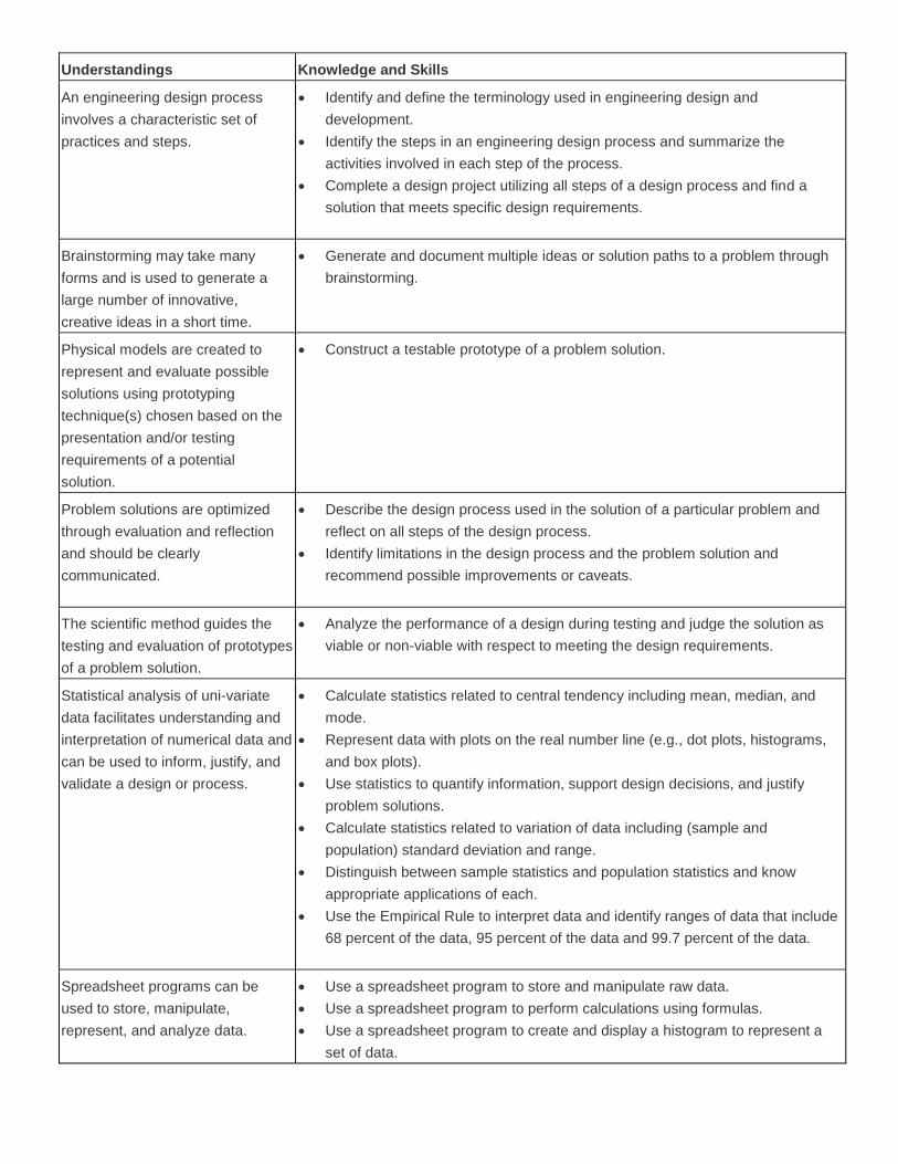
Statistical analysis of uni-variate
data facilitates understanding and
interpretation of numerical data and
can be used to inform, justify, and
validate a design or process.
Calculate statistics related to central tendency including mean, median, and
mode.
Represent data with plots on the real number line (e.g., dot plots, histograms,
and box plots).
Use statistics to quantify information, support design decisions, and justify
problem solutions.
Calculate statistics related to variation of data including (sample and
population) standard deviation and range.
Distinguish between sample statistics and population statistics and know
appropriate applications of each.
Use the Empirical Rule to interpret data and identify ranges of data that include
68 percent of the data, 95 percent of the data and 99.7 percent of the data.
Spreadsheet programs can be
used to store, manipulate,
represent, and analyze data.
Use a spreadsheet program to store and manipulate raw data.
Use a spreadsheet program to perform calculations using formulas.
Use a spreadsheet program to create and display a histogram to represent a
set of data.

Use function tools within a spreadsheet program to calculate statistics for a set
of data including mean, median, mode, quartiles, range, and standard
deviation.
Units and quantitative reasoning
can guide mathematical
manipulation and the solution of
problems involving quantities.
Use units to guide the solution to multi-step problems through dimensional
analysis and choose and interpret units consistently in formulas.
Choose a level of precision and accuracy appropriate to limitations on
measurement when reporting quantities.
Convert quantities between units in the SI and the US Customary measurement
systems.
Convert between different units within the same measurement system including
the SI and US Customary measurement systems.
Error is unavoidable when
measuring physical properties, and
a measurement is characterized by
the precision and accuracy of the
measurement.
Define accuracy and precision in measurement.
Evaluate and compare the accuracy and precision of different measuring
devices.
Measure linear distances (including length, inside diameter, and hole depth)
with accuracy using a scale, ruler, or dial caliper and report the measurement
using an appropriate level of precision.
The style of the engineering
graphics and the type of drawing
views used to detail an object vary
depending upon the intended use
of the graphic.
Identify and define technical drawing representations including isometric,
orthographic projection, oblique, perspective, auxiliary, and section views.
Technical drawings convey
information according to an
established set of drawing
practices which allow for detailed
and universal interpretation of the
drawing.
Determine the minimum number and types of views necessary to fully detail a
part.
Identify and correct errors and omissions in technical drawings including the
line work, view selection, view orientation, appropriate scale, and annotations.
Dimensions, specific notes (such
as hole and thread notes), and
general notes (such as general
tolerances) are included on
technical drawings according to
accepted practice and an
established set of standards so as
to convey size and location
information about detailed parts,
their features, and their
configuration in assemblies.
Dimension orthographic projections and section views of simple objects or parts
according to a set of dimensioning standards and accepted practices.
Identify and correctly apply chain dimensioning or datum dimensioning methods
to a technical drawing.
Identify and correct errors and omissions in the dimensions applied in a
technical drawing based on accepted practice and a set of dimensioning rules.
Hand sketching of multiple
representations to fully and
accurately detail simple objects or
parts of objects is a technique used
Hand sketch isometric views of a simple object or part at a given scale using
the actual object, a detailed verbal description of the object, a pictorial view of
the object, or a set of orthographic projections.

to convey visual and technical
information about an object.
Hand sketch orthographic projections at a given scale and in the correct
orientation to fully detail an object or part using the actual object, a detailed
verbal description of the object, or a pictorial and isometric view of the object.
Generate non-technical concept sketches to represent objects or convey
design ideas.
Technical professionals clearly and
accurately document and report
their work using technical writing
practice in multiple forms.
Organize and express thoughts and information in a clear and concise manner.
Adjust voice and writing style to align with audience and purpose.
Support design ideas using a variety of convincing evidence.
Utilize an engineering notebook to clearly and accurately document the design
process according to accepted standards and protocols to prove the origin and
chronology of a design.
Sketches, drawings, and images
are used to record and convey
specific types of information
depending upon the audience and
the purpose of the communication.
Create drawings or diagrams as representations of objects, ideas, events, or
systems.
In order to be an effective team
member, one must demonstrate
positive team behaviors and act
according to accepted norms,
contribute to group goals according
to assigned roles, and use
appropriate conflict resolution
strategies.
Demonstrate positive team behaviors and contribute to a positive team
dynamic.
Essential Questions (Unit-Specific)
1. How can statistical data and analysis be used to inform, justify, and validate a design or process?
2. If error is unavoidable in measurement, how can we indicate our confidence in the precision of a measurement we
make?
3. What is dimensional analysis and how can it help solve problems involving quantities?
4. Why do engineers generally adhere to a set of dimensioning standards and guidelines?
Key Term Definition
Accuracy The degree of closeness of measurements of a quantity to the actual (or accepted)
value.
Arrowheads Arrowheads are used to indicate the end of a dimension line or leader.
Caliper A measuring instrument having two adjustable jaws typically used to measure diameter
or thickness.
Class Interval A group of values that is used to analyze the distribution of data.
Convert To change money, stocks, or units in which a quantity is expressed into others of a
different kind.
Data Facts and statistics used for reference or analysis.

Data Set A group of individual values or bits of information that are related in some way or have
some common characteristic or attribute.
Dimension A measurable extent, such as the three principal dimensions of an object as in width,
height, and depth.
Dimension Lines A line which represents distance.
Dot Plot See line plot.
Frequency The rate at which something occurs over a particular period or in a given sample.
Graph A diagram showing the relation between variable quantities, typically of two variables
measured along a pair of lines at right angles.
Histogram A graph of vertical bars representing the frequency distribution of a set of data.
International
Organization for
Standardization (ISO)
A non-governmental global organization whose principal activity is the development of
technical standards through consensus.
International System
of Units (SI)
An international system of units of measurement consisting of seven base units.
Line Plot A method of visually displaying a distribution of data values where each data value is
shown as a dot or mark above a number line. Also known as a dot plot.
Mean A measure of center in a set of numerical data, computed by adding the values in a list
and then dividing by the number of values in the list.
Measure To determine the size, amount, or degree of an object by comparison with a standard
unit.
Median
A measure of center in a set of numerical data. The median of a list of values is the
value appearing at the center of a sorted version of the list – or the mean of the two
central values if the list contains an even number of values.
Mode The value that occurs most frequently in a given data set.
Normal Distribution A function that represents the distribution of variables as a symmetrical bell-shaped
graph.
Numeric Constraint A number value or algebraic equation that is used to control the size or location of a
geometric figure.
Precision The degree to which repeated measurements show the same result.
Scale 1. A straight-edged strip of rigid material marked at regular intervals and used to
measure distances. 2. A proportion between two sets of dimensions used in developing
accurate, larger or smaller prototypes, or models of design ideas.
Scatter Plot A graph in the coordinate plane representing a set of bivariate data.
Significant Digits The digits in a decimal number that carry meaning contributing to the precision or
accuracy of the quantity.
Standard Deviation The distance of a value in a population (or sample) from the mean value of the
population (or sample).
Statistics Collection of methods for planning experiments, obtaining data, organizing,
summarizing, presenting, analyzing, interpreting, and drawing conclusions based on
data.
Unit A standard quantity in terms of which other quantities may be expressed.
US Customary
Measurement System
System of measurement used in the United States.
Variation A change or slight difference in condition, amount, or level.
3.1a Measurement SI
The International System of Units (SI) is a system of units of measurement is also known as the metric system and uses powers of 10

A measurement always includes a value, units and uncertainty
Scientists and engineers often use significant digits to indicate the uncertainty of a measurement
Significant digits are digits in a decimal number that carry meaning indicating the certainty of the value
All digits you record for a measurement are considered significant
3.1b Measurement US Customary
3.2 Unit Conversion

3.3 Dial Calipers
3.4 Dimensioning

3.5 Statistics
3.6 Inferential Statistics


Unit 4 Modeling Skills - Overview
Preface
Effectively applying a design process often involves a wide variety of modeling activities. During the initial phases of the design
process, defining the problem and generating concepts brainstorming is often accompanied by concept modeling. Lists and
mind maps are often used to document design ideas and concepts. As research is performed, graphical modeling and/or
mathematical modeling can be used to represent gathered information. Graphical modeling can involve representing information
in the form of charts, graphs, maps, or geometric figures. Mathematical modeling involves representing a phenomenon or
behavior with an equation or a geometric representation. For instance, an environmental engineer who is developing a solution
to handle and dispose of solid waste in an area for the next 20 years may wish to represent the volume of solid waste produced
over the previous 20 years with a mathematical equation. The equation will allow the engineer to predict the waste production in
the future.
Design ideas and alternatives are often modeled graphically. If the design solution involves a physical object, designers
typically use sketching and drawing to represent design ideas. If the problem solution involves the design of systems or
processes, charts, graphs, and maps may be employed to represent the proposed designs. Early in the design process,
ideas are often sketched on paper for future refinement. As ideas are formalized, greater accuracy is required. This
refinement may involve converting sketches to computer models and formal technical drawings.
Today, computers and software applications are tools often used in the solution of engineering problems. Computer
modeling is frequently used to represent, analyze, document, and assess a design idea. Three-dimensional computer
modeling of products allows designers to virtually create, manipulate, and test products and system prior to building and
testing a physical model. A physical model is often desirable because it allows hands-on manipulation and testing of a
product or system in its intended operating environment. However, computer modeling is especially helpful when building
a physical model is difficult or expensive. For instance, in the case of large commercial and industrial buildings, which
must be designed to carry a variety of load conditions, computer modeling provides an inexpensive means through which
to model and test the load carrying capacity of the building structure. Or, if a chemical process is part of the design
solution, a computer program can simulate the proposed process and efficiently allow adjustment of design factors (such
as concentrations, temperature, and pressure) to hone in on a precise solution before large-scale physical testing is
performed.
If the design process is applied to the design of a consumer product, it is almost always necessary to build a physical
model for a variety of reasons. A physical model provides a representation of the design to which people can relate. They
can see the design intent. And, when the physical model is built to the design specifications, the product can be used for
the intended purpose and tested. In addition, physical models help potential consumers and investors understand the
product and can improve the chances of gaining financial support and customers.
The testing phase of the design process can also involve a variety of modeling techniques. Before testing can be
performed, the test(s) itself must be designed, which can require the use of concept, graphical, mathematical, computer
and/or physical models. Physical models of the design are often used to allow testing of the actual product. Computer
modeling is used to represent the product and test a design when physical testing is not feasible or is prohibitively
expensive. The data gathered during the testing phase of the design process is often represented with graphical and/or
mathematical modeling.
In this lesson students will learn how to create a product from conception to reality and will employ a variety of modeling
techniques. They will do this by applying the design process steps first-hand in the creation of their product. Students will
live the life of a product designer and create a solution to a problem that exists for a company.
Understandings

Students will understand that …
U1 – Technical professionals use a variety of models to represent systems, components, processes and other designs
including graphical, computer, physical, and mathematical models.
U2 – Computer aided drafting and design (CAD) software packages facilitate the creation of virtual 3D computer models of
parts and assemblies.
U3 – Physical models are created to represent and evaluate possible solutions using prototyping technique(s) chosen based
on the presentation and/or testing requirements of a potential solution.
U4 – Technical professionals clearly and accurayely document and report their work using technical writing practice in
multiple forms.
U5 – An equation is a statement of equality between two quantities that can be used to describe real phenomenon and solve
problems.
U6 – Solving mathematical equations and inequalities involves a logical process of reasoning and can be accomplished
using a variety of strategies and technological tools.
U7 – A function describes a special relationship between two sets of data and can be used to represent a real world
relationship and to solve problems.
Knowledge and Skills
KNOWLEDGE: Students will …
K1 –Explain the term “function” and identify the set of inputs for the function as the domain and the set of outputs from the
function as the range.
K2 – Be familiar with the terminology related to and the use of a 3D solid modeling program in the creation of solid models
and technical drawings.
K3 – Differentiate between additive and subtractive 3d solid modeling methods
SKILLS: Students will …
S1 – develop and/or use graphical, computer, physical and mathematical models as appropriate to represent or solve
problems.
S2 – Fabricate a simple object from technical drawings that may include an isometric view and orthographic projections. U1,
U5
S3 – Create three-dimensional solid models of parts within CAD from sketches or dimensioned drawings using appropriate
geometric and dimensional constraints. U1, U2
S4 – Generate CAD multi-view technical drawings, including orthographic projections and pictorial views, as necessary,
showing appropriate scale, appropriate view selection, and correct view orientation to fully describe a simple part according
to standard engineering practice. U1, U2
S5 – Construct a testable prototype of a problem solution. U1, U3
S6 – Analyze the performance of a design during testing and judge the solution as viable or non-viable with respect to
meeting the design requirements. U3
S7 – Create a set of working drawings to detail a design project. U1, U2
S8 – Organize and express thoughts and information in a clear and concise manner. U4
S9 – Utilize project portfolios to present and justify design projects. U4
S10 – Use a spreadsheet program to graph bi-variate data and determine an appropriate mathematical model using
regression analysis. U1, U7
S11 – Construct a scatter plot to display bi-variate data, investigate patterns of association, and represent the association
with a mathematical model (linear equation) when appropriate. U1, U5
S12 – Solve equations for unknown quantities by determining appropriate substitutions for variables and manipulating the
equations. U6
S13 – Use function notation to evaluate a function for inputs in its domain and interpret statements that use function notation
in terms of a context. U7
S14 – Build a function that describes a relationship between two quantities given a graph, a description of a relationship, or
two input-output pairs. U1, U7
S15 – Interpret a function to solve problems in the context of the data. U6, U7
S16 – Interpret the slope (rate of change) and the intercept (constant term) of a linear function in the context of data. U1, U5
S17 – Compare the efficiency of the modeling method of an object using different combinations of additive and subtractive
methods. U2
Essential Questions
EQ1 – How should one decide what information and/or artifacts to include in a portfolio? Should a portfolio always include
documentation on the complete design process?
EQ2 – Did you use every possible type of model during the design and construction of your puzzle cube? Describe each
model that you used?
EQ3 – How reliable is a mathematical model?
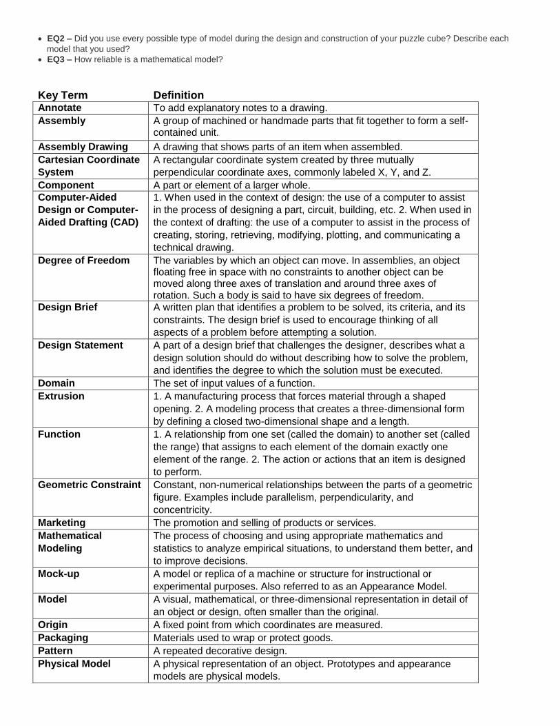
Key Term Definition Annotate To add explanatory notes to a drawing.
Assembly A group of machined or handmade parts that fit together to form a self-contained unit.
Assembly Drawing A drawing that shows parts of an item when assembled.
Cartesian Coordinate
System
A rectangular coordinate system created by three mutually
perpendicular coordinate axes, commonly labeled X, Y, and Z.
Component A part or element of a larger whole.
Computer-Aided
Design or Computer-
Aided Drafting (CAD)
1. When used in the context of design: the use of a computer to assist
in the process of designing a part, circuit, building, etc. 2. When used in
the context of drafting: the use of a computer to assist in the process of
creating, storing, retrieving, modifying, plotting, and communicating a
technical drawing.
Degree of Freedom The variables by which an object can move. In assemblies, an object floating free in space with no constraints to another object can be moved along three axes of translation and around three axes of rotation. Such a body is said to have six degrees of freedom.
Design Brief A written plan that identifies a problem to be solved, its criteria, and its
constraints. The design brief is used to encourage thinking of all
aspects of a problem before attempting a solution.
Design Statement A part of a design brief that challenges the designer, describes what a
design solution should do without describing how to solve the problem,
and identifies the degree to which the solution must be executed.
Domain The set of input values of a function.
Extrusion 1. A manufacturing process that forces material through a shaped
opening. 2. A modeling process that creates a three-dimensional form
by defining a closed two-dimensional shape and a length.
Function 1. A relationship from one set (called the domain) to another set (called
the range) that assigns to each element of the domain exactly one
element of the range. 2. The action or actions that an item is designed
to perform.
Geometric Constraint Constant, non-numerical relationships between the parts of a geometric
figure. Examples include parallelism, perpendicularity, and
concentricity.
Marketing The promotion and selling of products or services.
Mathematical
Modeling
The process of choosing and using appropriate mathematics and
statistics to analyze empirical situations, to understand them better, and
to improve decisions.
Mock-up A model or replica of a machine or structure for instructional or
experimental purposes. Also referred to as an Appearance Model.
Model A visual, mathematical, or three-dimensional representation in detail of
an object or design, often smaller than the original.
Origin A fixed point from which coordinates are measured.
Packaging Materials used to wrap or protect goods.
Pattern A repeated decorative design.
Physical Model A physical representation of an object. Prototypes and appearance
models are physical models.

Plane A flat surface on which a straight line joining any two points would
wholly lie.
Portfolio A collection of documents selected for a particular purpose which may
contain reflection on the contents of the documents or the related
purpose. Varieties of portfolio types exist and are used for different
purposes (e.g., project portfolio, course portfolio, longitudinal or growth
portfolio, showcase portfolio).
Prototype A full-scale working model used to test and improve a design concept
by making actual observations and necessary adjustments.
Range The set of output values of a function.
Revolution Creating a 3D solid or surface by revolving a 2D shape about an axis.
Rotation Turning around an axis or center point.
Round A rounded exterior blend between two surfaces.
Scale Model An enlarged or reduced representation of an object that is usually
intended for study purposes.
Scoring Making an impression or crease in a box blank to facilitate bending,
folding, or tearing.
Solid A three-dimensional body or geometric figure.
Solid Modeling A type of 3D CAD modeling that represents the volume of an object, not
just its lines and surfaces.
Subassembly An assembled part that is a part of a larger assembly.
Translation Motion in which all particles of a body move with the same velocity along parallel paths.
Working Drawings Drawings that convey all of the information needed to manufacture and
assemble a design.
4.1 Modeling – Technical drawings are used to communicate engineering designs to those who will build the
product. In order that the drawings are interpreted correctly by all stake holders, the drawings should be created using accepted standard practice and should include all information necessary to correctly manufacture and/or assemble the product.
– Concept Modeling: Listing or mapping the concepts involved in a design or process under
investigation.

– Graphical Modeling: Representing information in the form of charts, graphs, maps, or geometric figures.
–
– Mathematical Modeling: Using mathematical equations or geometric representations to predict or
model a phenomenon or behavior.
– Computer Modeling: Using a computer and software to create a representation of an object or concept.
–
– Physical Modeling: Using physical materials to create a representation of an object or concept. – Mock-up: An appearance model used to present the general concept of a design – Scale Model: A representation of a design that is either larger or smaller than the actual model – Prototype: A working model of the actual design

–
Unit 5 Geometry of Design - Overview
Preface Geometric shapes are found everywhere. Take a moment to analyze products or objects you use every day. Geometric
shapes and solids are the basis of these products. Engineers who have a strong understanding of these shapes, solids,
and other geometric relationships can help designers develop and create solutions to a variety of problems. As designers

progress through the design process and these design solutions are formalized, the level of accuracy and precision in the
design specifications must increase. Conceptual sketches are converted to computer models and formal drawings, which
include annotations describing the size and characteristics of the design features. A strong understanding of shapes and
other geometric relationships is necessary to effectively and efficiently develop these computer and graphic
representations.
Designers have used Computer Aided Design (CAD) programs for decades to refine ideas and generate images that
manufacturers and other professionals can use to make profitable solutions to problems. The development of three-
dimensional CAD solid modeling programs has resulted in significant increases in the quality of complex designs while
drastically reducing the amount of time needed to produce those designs. Some engineers feel that the development of
three-dimensional CAD solid modeling programs has made engineering more engaging and fun not to mention more
accurate and precise.
Today’s software that employs parametric design functionality requires an understanding of geometric relationships, such
as perpendicular, parallel, and tangent. Students will transfer their knowledge of geometric relationships to parametric
modeling.
In this lesson students will apply the skills learned in prior units. They will learn how to calculate the area of two-
dimensional shapes. Students will also learn how to calculate the surface area, volume, and weight of three-dimensional
solids and the interaction of volume and weight to determine material density. Students will also improve their skill in the
use of CAD modeling software to enhance their understanding of plane and solid geometry.
Understandings
Students will understand that …
U1 – Geometric shapes and forms are described and differentiated by their characteristic features.
U2 – Physical properties of objects are used to describe and model objects and can be used to define design requirements, as a means to compare potential solutions to a problem, and as a tool to specify final solutions.
U3 – Computer aided design (CAD) and drafting software packages incorporate the application of a variety of geometric and dimensional constraints and model features to accurately represent objects.
Knowledge and Skills
KNOWLEDGE: Students will …
K1 – Identify types of polygons including a square, rectangle, pentagon, hexagon, and octagon.
K2 – Differentiate between inscribed and circumscribed shapes.
K3 – Identify and differentiate geometric constructions and constraints (such as horizontal lines, vertical lines, parallel lines, perpendicular lines, colinear points, tangent lines, tangent circles, and concentric circles) and the results when applied to sketch features within a 3D solid modeling environment.
K4 – Distinguish between the meanings of the terms weight and mass.
K5 – Define the term “physical property” and identify the properties of length, volume, mass, weight, density, and surface area as physical properties.
K6 – Identify three-dimensional objects generated by rotations of two-dimensional shapes and vice-versa.
SKILLS: Students will …
S1 – Solve real world and mathematical problems involving area and surface area of two- and three-dimensional objects composed of triangles, quadrilaterals, polygons, cubes, right prisms, cylinders, and spheres. U1, U2
S2 – Create three-dimensional solid models of parts within CAD from sketches or dimensioned drawings using appropriate geometric and dimensional constraints and model features. U1, U3
S3 – Measure mass with accuracy using a scale and report the measurement using an appropriate level of precision. U2
S4 – Measure volume with accuracy and report the measurement with an appropriate level of precision. U2
S5 – Calculate a physical property indirectly using available data or perform appropriate measurements to gather the necessary data (e.g., determine area or volume using linear measurements or determine density using mass and volume measurements). U2
S6 – Solve volume problems using volume formulas for rectangular solids, cylinders, pyramids, cones, and spheres. U2
S7 – Use physical properties to solve design problems (e.g., design an object or structure to satisfy physical constraints or minimize cost). U2

S8 – Assign a specific material (included in the software library) to a part and use the capabilities of the CAD software to determine the mass, volume, and surface area of an object for which a 3D solid model has been created.
S9 – Assign a density value to a new material (not included in the software library) and apply the material to a 3D solid model within CAD software in order to determine the physical properties of the object.
Essential Questions
EQ1 – What advantage(s) do Computer Aided Design (CAD) and Drafting provide over traditional paper and pencil design? What advantages does paper and pencil design provide over CAD?
EQ2 – Which high school math topic/course, Algebra or Geometry, is more closely related to engineering? Justify your answer.
EQ3 – How does the material chosen for a product impact the design of the product?
Term Definition
Acute Triangle A triangle that contains only angles that are less than 90 degrees.
Angle The amount of rotation needed to bring one line or plane into coincidence with
another, generally measured in radians or degrees.
Area The number of square units required to cover a surface.
Axis 1. An imaginary line through a body, about which it rotates. 2. An imaginary line about
which a regular figure is symmetrically arranged. 3. A fixed reference line for the
measurement of coordinates.
Center of Gravity A 3D point where the total weight of the body may be considered to be concentrated.
Centroid A 3D point defining the geometric center of a solid.
Circle A round plane figure whose boundary consists of points equidistant from the center
Circumscribe 1. A triangle located round a polygon such as a circle. 2 To draw a figure around
another, touching it at points but not cutting it.
Cylinder A solid composed of two congruent circles in parallel planes, their interiors, and all the
line segments parallel to the axis with endpoints on the two circles.
Density The measure of mass density is a measure of mass per volume.
Diameter A straight line passing from side to side through the center of a circle or sphere.
Ellipse A shape generated by a point moving in a plane so that the sum of its distances from
two other points (the foci) is constant and equal to the major axis
Fillet A curve formed at the interior intersection between two or more surfaces.
Inscribe To draw a figure within another so that their boundaries touch but do not intersect.
Mass The amount of matter in an object or the quantity of the inertia of the object.
Meniscus The curved upper surface of a liquid column that is concave when the containing walls
are wetted by the liquid and convex when not.
Obtuse Triangle A triangle with one angle that is greater than 90 degrees.
Parallelogram A four-sided polygon with both pairs of opposite sides parallel.
Pi (π) The numerical value of the ratio of the circumference of a circle to its diameter of
approximately 3.14159.
Polygon Any plane figure bounded by straight lines.
Principal Axes The lines of intersection created from three mutually perpendicular planes, with the
three planes’ point of intersection at the centroid of the part.
Prism A solid geometric figure whose two ends are similar, equal, and parallel rectilinear
figures, and whose sides are parallelograms.
Quadrilateral A four-sided polygon.
Radius A straight line from the center to the circumference of a circle or sphere.

Rectangle A parallelogram with 90 degree angles. A square is also a rectangle.
Regular Polygon A polygon with equal angles and equal sides.
Right Triangle A triangle that has a 90 degree angle.
Round Two or more exterior surfaces rounded at their intersections.
Square A regular polygon with four equal sides and four 90 degree angles.
Surface Area The squared dimensions of the exterior surface
Tangent A straight or curved line that intersects a circle or arc at one point only.
Title Block A table located in the bottom right-hand corner of an engineering drawing that
identifies, in an organized way, all of the necessary information that is not given on the
drawing itself. Also referred to as a title strip.
Triangle A polygon with three sides.
Vertex Each angular point of a polygon, polyhedron, or other figure.
Volume The amount of three-dimensional space occupied by an object or enclosed within a
container.
Quadrilateral A four-sided polygon.
5.1 Geometric Shapes

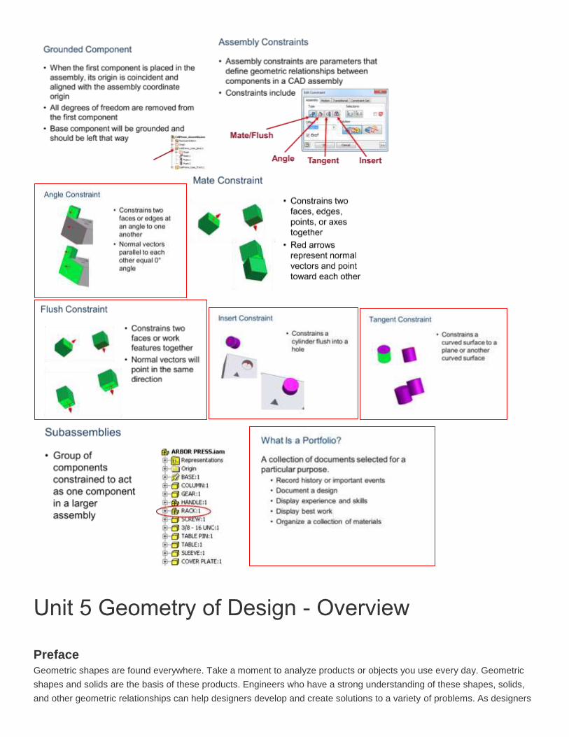
5.2 Geometric Constraints
Parallel- every point on the lines are equal distance from each other; thus, the lines never intersect
Perpendicular- lines intersect at a 90 degree angle
Fix- keeps a point to a point on the coordinate system
Collinear- two lines to be the same line- the lay along the same line
Horizontal- causes line to be parallel to X axis
Vertical- causes line to be parallel to Y axis
Tangent- a line shares only one point with a circle or arc
Concentric- circles, arcs, or ellipses to have the same center point
Coincident- attaches two points together
Equal- causes lines have the same length and circles and arcs to have the same radius
5.3 Density

5.4 Geometric Solid properties

A wood board is one of a dozen different parts in a homemade robot kit. The width, depth, and height dimensions of the board are 3.5 x 17 x 1.5 inches, respectively. The board is made from southern yellow pine, which has an air dry weight density of .021 lb/in.3.
a. What is the volume of the wood board?
b. What is the surface area of the wood board?
c. What is the weight of the wood board?
d. If one gallon of paint will cover 57,600 square inches, how many gallons would be
needed to give two coats of paint to 25,000 boards? Round your answer to the nearest gallon.
e. What will the total cost be to ship the 25,000 boards to a facility for assembling into the
finish kit form if the shipping rate is $4.25 per pound?
5.5 CAD modeling
REVOLVE
CIRCULAR PATTERN

RECTANGULAR PATTERN
SWEEP
5.6 Physical Property Analysis