ní centrála lpb oci611 - alpat.com.pl · −mit der bediensoftware acs600 direkt via pc und rs-...
TRANSCRIPT

Siemens Building Technologies / Landis & Staefa Division 74 319 0172 0 02.10.2000 1/18
G253374 319 0172 0
de Installationsanleitung Kommunikationszentrale für LPBen Installation Instructions Communication Centre for LPBfr Instructions d’installation Centrale de communication pour LPBnl Installatievoorschriften Communicatiecentrale voor LPBit Istruzioni di montaggio Centrale di comunicazione LPBes Instrucciones de Montaje Unidad central de comunicación para LPBpl Instrukcja montażu Centrala komunikacyjna LPBcs Montážní list Komunika ční centrála LPB OCI611...
de Deutsch
Montage
Festlegen des Montageortes• In trockenem Raum• Einbaumöglichkeiten:
− Kompaktstation− Schaltschrank (Front, Innenwand, auf Wandhalteschiene)− Schalttafel− schräge Frontfläche eines Schaltpultes
• Zulässige Umgebungstemperatur ist 0...50 °C• Auf gute Zugänglichkeit für den Service achten
Elektrische Installation• Örtliche Vorschriften für Elektroinstallationen sind zu beachten• Die Trennung der Zentrale vom AC 230 V-Netz muss über eine
beschriftete und leicht zugängliche Sicherung mit 10/16 AAuslösestrom erfolgen
• Zulässige Leitungslängen:− LPB: siehe folgende Dokumente
Systemgrundlagen Datenblatt CE1N2030Projektierungsgrundlagen Datenblatt CE1N2032Systemprojektierung Basisdokumentation CE1P2370
− RS-232: max. 15 m
MontierenDie Zentrale kann in beliebiger Lage mit folgenden Befesti-gungsmöglichkeiten montiert werden:
Wandmontage1. Gerät an die Wand halten und Befestigungslöcher anzeichnen2. Löcher bohren3. Gerät festschrauben
536
3Z05
Hinweise zur Wandmontage:Für die Montage mit Schrauben sind vier Bohrlöcher vorhan-den. Der Sockel hat erhöhte Auflageflächen.Schrauben: ∅ max. 3,5 mm. Bohrplan siehe Abschnitt«Maßbilder»
Montage auf Wandhalteschiene1. Wandhalteschiene anbringen2. Gerät aufstecken3. Wenn nötig, Gerät fixieren (abhängig vom Schienentyp)
536
3Z04
Hinweise zur Schienenmontage:Der Sockel hat eine Schnappvorrichtung für die Montage aufWandhalteschienen (Typ EN 50022-35x7,5) und ist miteinem Schraubendreher ausklinkbar
Verdrahten1. Anschlussklemmen verdrahten:
oben: Kleinspannungunten: Netzspannung
2. Eine Zugentlastung für die Leitungen zu denKlemmen N und L (AC 230 V) ist zwingend nötig:
5363
Z03
3. Die Leitungen müssen mit Kabelbindern an den vorgesehe-nen Laschen am Gehäusesockel fixiert werden
Klemmenabdeckungen• Ist der Berührungsschutz nicht gegeben (z.B. in
Heizungsräumen, Zwischenböden und -decken):Montage immer mit Klemmenabdeckungen
• Nur einfach isolierte Leitungen zu den Klemmen Nund L (AC 230 V) müssen mit einem Isolierschlauchversehen werden:
5363
Z13

2/18 02.10.2000 74 319 0172 0 Siemens Building Technologies / Landis & Staefa Division
• Ist der Berührungsschutz gegeben (z.B. in Vertei-lerkästen oder Schaltschränken):Montage ohne Klemmenabdeckungen zulässig
• Die Klemmenabdeckung auf der Netzseite muss mitden zwei mitgelieferten Kabelbindern gesichert wer-den:
536
3Z
07
Inbetriebnahme
Handhabung und Bedienung1 2 3 4 5
6 7 8
5363
Z06
ON
1 2
1 RS-232-Schalter (Schalter «2» ist ohne Funktion)2 Modemreset-Taster3 RS-232-Steckbuchse4 Anschlussklemmen für Kleinspannung5 LPB-Taster6 Anschlussklemmen für Netzspannung7 Betriebsanzeige (grüne LED)8 Alarmanzeige (rote LED)
BetriebsanzeigeDie grüne LED zeigt den jeweiligen Betriebszustand der Zentralean:• LED leuchtet: Netzspannung vorhanden• LED blinkt: Kommunikation via LPB und/oder RS-232Die Leuchtdiode ist auch bei montierter Klemmenabdeckungsichtbar.
AlarmanzeigeDie rote LED zeigt den jeweiligen Alarmzustand der Zentrale an:• LED leuchtet nicht: Kein Fehler und kein Alarm vorhanden• LED leuchtet: Fehler eines oder mehrerer LPB-Regler steht an• LED blinkt: Interner Fehler in der ZentraleDie Leuchtdiode ist auch bei montierter Klemmenabdeckungsichtbar.
RS-232-SchalterMit ihm wird gewählt, ob die Zentrale an der RS-232 mit einem
Modem (Schalterstellung ) oder direkt mit einem PC (Schalter-
stellung ) verbunden ist.
LPB-TasterDer LPB-Taster dient zum Starten des Suchlaufs und damit zumErstellen des internen Geräteverzeichnisses.Weitere Möglichkeiten zum Erstellen des Geräteverzeichnisses:siehe Kapitel «Inbetriebnahme», Abschnitt «Vorgehen», Schritt 8.Nach erfolgtem Suchlauf kann die Anzahl der im Verzeichnisaufgenommenen Geräte jederzeit mit einem kurzen Druck(<0,5 Sekunden) auf den LPB Taster abgerufen werden.
Modemreset-TasterDer Modemreset-Taster initialisiert das Modem neu. Anschließendnimmt die Zentrale mit der Leitstelle Verbindung auf und setzteinen Statusrapport ab.
Inbetriebnahme
Hinweise:• Bei Betrieb mit PC: Im Direktbetrieb über RS-232 mit einem PC
muss immer ein Nullmodem zwischen den beiden Gerätenverwendet werden.
• Die Einstellungen in Schritt 7 können auch im voraus vorge-nommen werden.
Vorgehen1. Betriebsspannung noch NICHT einschalten2. Klemmenabdeckungen, wenn vorhanden, abnehmen3. Verdrahtung gemäß Anlageschaltplan prüfen4. Der RS-232-Schalter muss für die Inbetriebnahme auf der
Stellung stehen (direkte Kommunikation über RS-232 mitPC)
5. Klemmenabdeckung auf der Netzseite, wenn erforderlich,wieder montieren
6. Betriebsspannung einschalten7. Die folgenden Einstellungen müssen mit der Bediensoftware
ACS600 über die RS-232-Schnittstelle oder mit dem Servi-ce-Tool ACS69 via Kommunikations-Interface OCI69 überden LPB vorgenommen werden:− Telefonnummer 1− Tel. Nr. Anlage *− Namen für die Anlage, für die beiden digitalen Eingänge und
für die angeschlossenen Regler *− Modem Initialisierungsstring 1 / 2 *− Baudrate RS-232 *− Modem Wählstring *− Modem Abbruchstring *− Modemstring für Modemsuffix *− Modemstring für Modemreset *
* fakultativ
8. Geräteverzeichnis erstellen. Das kann geschehen:− Durch Drücken des LPB-Tasters während 6 Sekunden− Mit dem Service-Tool ACS69 via Kommunikations-
Interface OCI69 über den LPB, mittels Suchlauf oder Pa-rametrierung
− Mit der Bediensoftware ACS600 direkt via PC und RS-232, mittels Suchlauf oder Parametrierung
− Mit der Bediensoftware ACS600 über Modem von derLeitstelle aus, mittels Suchlauf oder Parametrierung
Hinweise • Das Erstellen des Geräteverzeichnisses mitHilfe des Suchlaufes wird nur empfohlen, wenndie Anzahl Geräte am LPB die am OCI611...maximal anschließbare Anzahl Geräte nichtübersteigt (je nach Zentralentyp 1, 5 oder 16).
• Weder die Zentrale OCI611... noch das Kom-munikations-Interface OCI69 speisen den Bus.Um eine Kommunikation zu ermöglichen, musssich immer mindestens 1 LPB-Regler am Busbefinden.
9. Die Anzahl der gefundenen LPB-Regler wird an der Be-triebsanzeige (grüne LED) angezeigt. Pro LPB-Reglerleuchtet die LED kurz auf.
10. Weitere Parametrierungen, die ebenfalls über das Service-Tool ACS69 (bzw. Bediensoftware ACS600) gemacht wer-den müssen bzw. können, sind von der Anlage abhängig(z.B. Alarmierungsart der Alarmquellen).
11. Die Verbindung über Modem zur Leitstelle muss nach er-folgter Inbetriebnahme unbedingt kontrolliert werden, umunnötige Servicegänge aufgrund nicht funktionierender Mo-demkommunikation zu verhindern.Dazu muss jedoch vor dem Kommunikationsaufbau der RS-
232-Schalter in die Stellung gebracht werden. Sobalddas Modem mit der Zentrale verbunden ist, kann der Mo-demreset-Taster während 2 Sekunden gedrückt werden.Fehler beim Kommunikationsaufbau werden an der Alarm-anzeige (rote LED) angezeigt.
12. Klemmenabdeckung auf der Kleinspannungsseite montieren

Siemens Building Technologies / Landis & Staefa Division 74 319 0172 0 02.10.2000 3/18
(Schluss-)Kontrolle vor Ort1. Leuchtet die grüne LED (Betriebszustand)?2. Ist die rote LED (Alarmanzeige) dunkel?3. LPB-Taster kurz drücken. Entspricht die Anzahl der mit der
grünen LED angezeigten Regler der Anzahl der Regler, diein der Anlage vom OCI611... unterstützt werden sollen?
4. Arbeitet die Kommunikation zur Leitstelle korrekt?
5. Ist der RS-232-Schalter in der Stellung ?
en English
Installation
Place of installation• In a dry room• Mounting choices:
− In a compact station− In a control panel (in the front, on the inner wall, or on a wall
mounting rail)− On a control panel front− In the sloping front of a control desk
• Permissible ambient temperature: 0...50 °C• The unit must be easily accessible for service staff
Electrical installation• The local regulations for electrical installations must be com-
plied with• The isolation of the central unit from the AC 230 V mains sup-
ply must be ensured by a labeled and easily accessible fusewith a release current of 10/16 A
• Permissible cable lengths:− LPB: refer to the following pieces of documentation:
Basic System Data: Data sheet CE1N2030Basic Engineering Data: Data sheet CE1N2032System Engineering: Basic Documentation CE1P2370
− RS-232: max. 15 m
MountingThe central unit can be mounted in any position. The followingmounting choices exist:
Wall mounting1. Hold unit against the wall and mark fixing holes on the wall.2. Drill holes.3. Screw unit to the wall.
536
3Z05
Notes on wall mounting:For wall mounting with screws, there are 4 fixing holesavailable. The base has raised mounting surfaces.Screws: max. 3.5 mm dia.; for drilling template, refer to«Dimensions».
Mounting on a wall mounting rail1. Fit rail.2. Fit unit to the rail.3. Secure unit (depending on the type of rail used).
536
3Z04
Notes on rail mounting:The base has a snap-on facility for wall mounting rails (typeEN 50 022-35x7.5) and can be removed with a screwdriver.
Wiring
1. Wire up the connection terminals:Top: low voltageBottom: mains voltage
2. Cable tension relief for the cables connected toterminals N and L (AC 230 V) is mandatory:
5363
Z03
3. The cables must be secured to the base of the unit with thehelp of cable ties.
Terminal covers
• If there is no protection against electric shock haz-ard (e.g. in heating rooms, false ceilings or falsefloors): always use terminal covers
• Only single-insulated cables connected to terminalsN and L (AC 230 V) must be provided with insulat-ing sheath:
5363
Z13
• If protection against electric shock hazard is en-sured (e.g. in control panels or cabinets):mounting without terminal covers is permitted
• The terminal cover on the mains voltage side mustbe secured with the 2 cable ties provided
536
3Z
07
4/18 02.10.2000 74 319 0172 0 Siemens Building Technologies / Landis & Staefa Division
Commissioning
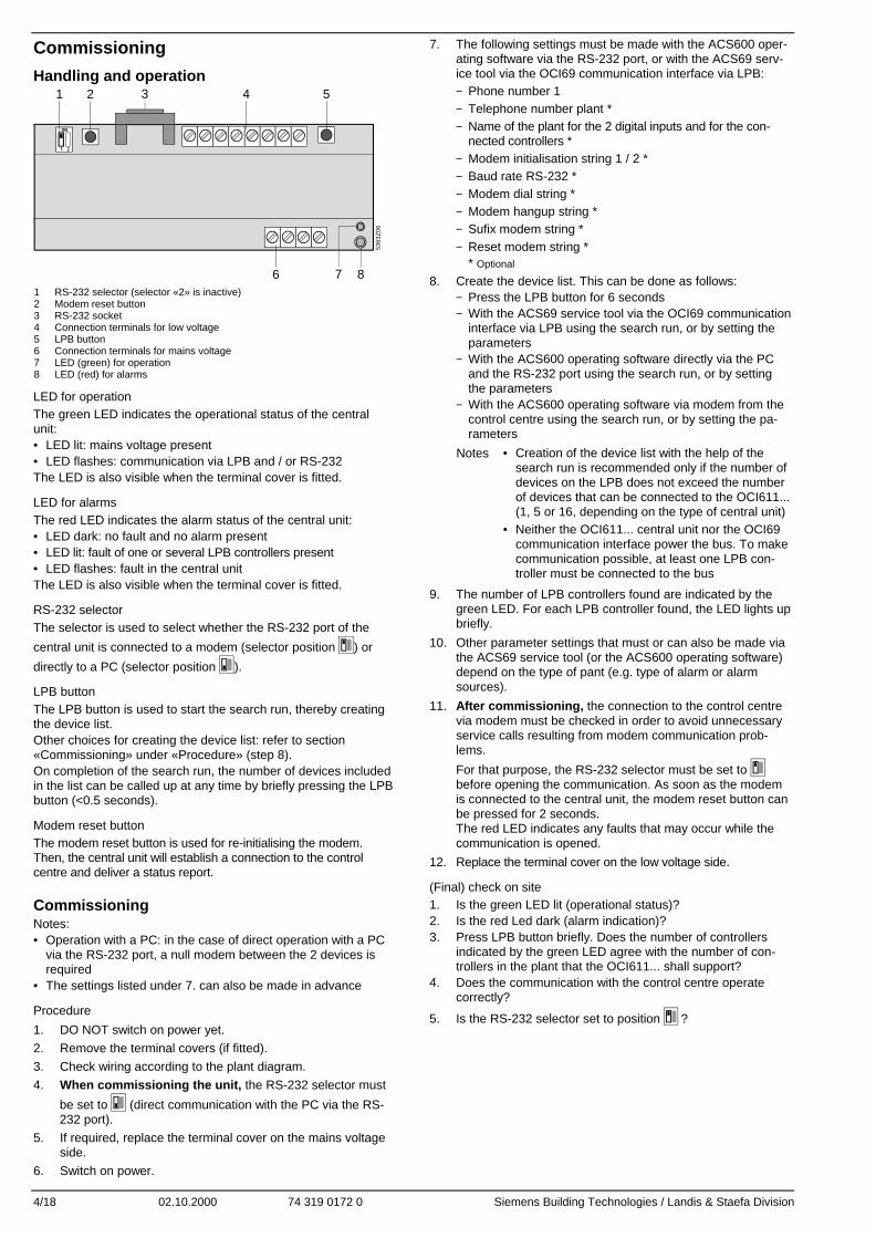
Handling and operation1 2 3 4 5
6 7 8
5363
Z06
ON
1 2
1 RS-232 selector (selector «2» is inactive)2 Modem reset button3 RS-232 socket4 Connection terminals for low voltage5 LPB button6 Connection terminals for mains voltage7 LED (green) for operation8 LED (red) for alarms
LED for operationThe green LED indicates the operational status of the centralunit:• LED lit: mains voltage present• LED flashes: communication via LPB and / or RS-232The LED is also visible when the terminal cover is fitted.
LED for alarmsThe red LED indicates the alarm status of the central unit:• LED dark: no fault and no alarm present• LED lit: fault of one or several LPB controllers present• LED flashes: fault in the central unitThe LED is also visible when the terminal cover is fitted.
RS-232 selectorThe selector is used to select whether the RS-232 port of the
central unit is connected to a modem (selector position ) or
directly to a PC (selector position ).
LPB buttonThe LPB button is used to start the search run, thereby creatingthe device list.Other choices for creating the device list: refer to section«Commissioning» under «Procedure» (step 8).On completion of the search run, the number of devices includedin the list can be called up at any time by briefly pressing the LPBbutton (<0.5 seconds).
Modem reset buttonThe modem reset button is used for re-initialising the modem.Then, the central unit will establish a connection to the controlcentre and deliver a status report.
CommissioningNotes:• Operation with a PC: in the case of direct operation with a PC
via the RS-232 port, a null modem between the 2 devices isrequired
• The settings listed under 7. can also be made in advance
Procedure
1. DO NOT switch on power yet.
2. Remove the terminal covers (if fitted).
3. Check wiring according to the plant diagram.
4. When commissioning the unit, the RS-232 selector must
be set to (direct communication with the PC via the RS-232 port).
5. If required, replace the terminal cover on the mains voltageside.
6. Switch on power.
7. The following settings must be made with the ACS600 oper-ating software via the RS-232 port, or with the ACS69 serv-ice tool via the OCI69 communication interface via LPB:− Phone number 1− Telephone number plant *− Name of the plant for the 2 digital inputs and for the con-
nected controllers *− Modem initialisation string 1 / 2 *− Baud rate RS-232 *− Modem dial string *− Modem hangup string *− Sufix modem string *− Reset modem string *
* Optional
8. Create the device list. This can be done as follows:− Press the LPB button for 6 seconds− With the ACS69 service tool via the OCI69 communication
interface via LPB using the search run, or by setting theparameters
− With the ACS600 operating software directly via the PCand the RS-232 port using the search run, or by settingthe parameters
− With the ACS600 operating software via modem from thecontrol centre using the search run, or by setting the pa-rameters
Notes • Creation of the device list with the help of thesearch run is recommended only if the number ofdevices on the LPB does not exceed the numberof devices that can be connected to the OCI611...(1, 5 or 16, depending on the type of central unit)
• Neither the OCI611... central unit nor the OCI69communication interface power the bus. To makecommunication possible, at least one LPB con-troller must be connected to the bus
9. The number of LPB controllers found are indicated by thegreen LED. For each LPB controller found, the LED lights upbriefly.
10. Other parameter settings that must or can also be made viathe ACS69 service tool (or the ACS600 operating software)depend on the type of pant (e.g. type of alarm or alarmsources).
11. After commissioning, the connection to the control centrevia modem must be checked in order to avoid unnecessaryservice calls resulting from modem communication prob-lems.
For that purpose, the RS-232 selector must be set tobefore opening the communication. As soon as the modemis connected to the central unit, the modem reset button canbe pressed for 2 seconds.The red LED indicates any faults that may occur while thecommunication is opened.
12. Replace the terminal cover on the low voltage side.
(Final) check on site1. Is the green LED lit (operational status)?2. Is the red Led dark (alarm indication)?3. Press LPB button briefly. Does the number of controllers
indicated by the green LED agree with the number of con-trollers in the plant that the OCI611... shall support?
4. Does the communication with the control centre operatecorrectly?
5. Is the RS-232 selector set to position ?

Siemens Building Technologies / Landis & Staefa Division 74 319 0172 0 02.10.2000 5/18
fr Français
Montage
Choix du lieu de montage• Dans un local sec• Possibilités de montage :
− Station compacte− Armoire de commande (façade, paroi interne, rail support)− Tableau de commande− Façade d'un pupitre de commande
• Température ambiante admissible 0...50 °C• Veiller à l'accessibilité pour la maintenance
Installation électrique• Respecter les prescriptions locales pour les installations élec-
triques• La séparation entre la centrale et le réseau 230 V~ doit être
effectuée via un fusible repéré et aisément accessible aveccourant de déclenchement de 10/16 A
• Longueurs de ligne admissibles :− Bus local (LPB) : voir documents suivants
Bases du système Fiche CE1N2030Principes pour l'ingénierie Fiche CE1N2032Ingénierie du système Information produit CE1P2370
− RS-232 : max. 15 m
MontageLa centrale peut être montée dans n'importe quelle position.Fixations possibles :
Montage mural1. Maintenir l'appareil contre la paroi et marquer l'emplacement
des trous de fixation2. Percer les trous3. Fixer l'appareil en serrant les vis
536
3Z05
Indications pour le montage mural :4 trous sont prévus pour le montage à l'aide de vis. Le soclecomporte des surfaces d'appui surélevées.Vis : ∅ 3,5 mm max. Plan de perçage, cf. §«Encombrements»
Montage sur rail support1. Monter le rail support2. Embrocher l'appareil3. Si nécessaire, fixer l'appareil (selon le type de rail)
536
3Z04
Indications pour le montage sur rail :Le socle comporte un dispositif d'encliquetage pour montagesur rails supports (type EN50022-35x7,5) et est débrochableà l'aide d'un tournevis
Câblage
1. Câbler les bornes de raccordement :en haut : très basse tensionen bas : tension secteur
2. Utiliser impérativement un arrêtoir de câblepour les raccordements des bornes N et L(230 V~) :
5363
Z03
3. Les fils doivent être fixés par des serre-câble sur les bridesprévues sur le socle
Couvre-bornes
• En l'absence de protection contre les contactsaccidentels (par ex. dans les chaufferies, les fauxplanchers et les faux plafonds) :toujours prévoir des couvre-bornes
• Seuls les câbles à isolation simple vers les bornesN et L (230 V~) doivent être équipés d'une gained'isolation :
5363
Z13
• S'il existe une protection contre les contacts acci-dentels (dans des coffrets de répartition ou des ar-moires électriques par exemple) :un montage sans couvre-bornes est admissible
• Le couvre-bornes côté secteur doit être fixé avecles deux deux serre-câble fournis :
536
3Z
07

6/18 02.10.2000 74 319 0172 0 Siemens Building Technologies / Landis & Staefa Division
Mise en service
Manipulation et commande1 2 3 4 5
6 7 8
5363
Z06
ON
1 2
1 Commutateur RS-232 (le commutateur "2" n'a aucune fonction)2 Touche de remise à zéro du modem3 Prise RS-2324 Bornes de raccordement pour très basse tension5 Touche de bus local6 Bornes de raccordement pour tension secteur7 Affichage de fonctionnement (LED verte)8 Affichage d'alarme (LED rouge)
Affichage de fonctionnementLa LED verte indique l'état de fonctionnement de la centrale :• LED allumée : tension secteur présente• LED clignote : communication via bus local et/ou RS-232La diode électroluminescente est visible même lorsque le couvre-bornes est monté.
Affichage des alarmesLa LED rouge indique l'état d'alarme de la centrale :• LED éteinte : pas de défaut ni d'alarme• LED allumée : défaut d'un ou plusieurs appareils du bus en
attente• LED clignote : défaut interne dans la centraleLa diode électroluminescente est visible même lorsque le couvre-bornes est monté.
Commutateur RS-232Permet de déterminer si la centrale est reliée à l'interface RS-232
par un modem (position du commutateur ) ou directement par
un PC (position du commutateur ).
Touche de bus localLa touche de bus local sert à lancer la recherche et donc à établirla liste interne des appareils.Autres possibilités pour créer cette liste : cf. chapitre «Mise enservice » § «Procédure», phase 8.Après la recherche, on peut appeler à tout moment le nombred'appareils enregistrés dans la liste en appuyant brièvement(< 0,5 s) sur la touche de bus local.
Touche de remise à zéro du modemLa touche de remise à zéro du modem réinitialise le modem. Lacentrale reprend ensuite contact avec le centre de conduite ettransmet un rapport d'état.
Mise en serviceRemarques :• Fonctionnement avec PC : en fonctionnement direct avec un
PC, via RS-232, toujours utiliser un null-modem entre les 2 ap-pareils.
• Les réglages de la phase 7 peuvent aussi être effectués àl'avance.
Procédure1. ATTENDRE avant de mettre sous tension2. Enlever le cas échéant le couvre-bornes3. Vérifier le câblage à l’aide du schéma de l’installation4. Pour la mise en service , le commutateur RS-232 doit se
trouver en position (communication directe avec le PC viaRS-232)
5. Remonter si nécessaire les couvre-bornes côté secteur
6. Mettre sous tension7. Les réglages suivants doivent être effectués au travers du
bus local (LPB) soit avec le logiciel de commande ACS600par l'intermédiaire de l'interface RS-232, soit avec l'outil deservice ACS69 via l'interface de communication OCI69 :− Numéro de téléphone du centre de conduite− Numéro de téléphone de l'installation *− Noms pour la centrale, les deux entrées numériques et les
régulateurs raccordés *− Chaîne pour l'initialisation du modem *− Vitesse de transmission du modem *− Chaîne du modem pour commande de sélection *− Chaîne du modem pour commande de raccroché *− Chaîne du modem pour suffixe du modem *− Chaînes du modem pour commande de remise à zéro du
modem ** facultatif
8. Etablir la liste des appareils. Ceci peut se faire :− en appuyant pendant 6 s sur la touche de bus local− soit au travers du bus, à l'aide de l'outil de service ACS69
via l'interface de communication OCI69, par recherche ouparamétrage
− soit directement via PC et RS-232, à l'aide du logiciel decommande ACS600, par recherche ou paramétrage
− soit par modem à partir du centre de conduite, à l'aide dulogiciel de commande ACS600, par recherche ou para-métrage
Remarques • L'établissement de la liste des appareils àl'aide du la "Recherche" n'est conseillé que sile nombre d'appareils sur le bus ne dépassepas la quantité maximale d'appareils raccor-dables à l'OCI611 (1, 5 ou 16 selon le type decentrale).
• Le bus n'est alimenté ni par la centraleOCI611... ni par l'interface de communicationOCI69. Pour permettre la communication ilfaut toujours avoir au minimum 1 régulateurLPB raccordé au bus.
9. Le nombre de régulateurs LPB détectés est indiqué surl'affichage de fonctionnement ( LED verte). La LED s'allumebrièvement pour chaque régulateur détecté.
10. Les autres paramétrages qui peuvent ou doivent égalementêtre réglés à l'aide de l'outil de service ACS69 (ou du logicielde commande ACS600) dépendent de l'installation (cycled'alarme par exemple).
11. La liaison par modem avec le centre de conduite doit abso-lu-ment être contrôlée après la mise en service , pour éviterles inutiles interventions de service dues au non-fonctionnement de la communication par modem.Pour cela, il faut toutefois placer le commutateur RS-232
dans la position , avant l'établissement de la communica-tion. Dès que le modem est relié à la centrale, on peut ap-puyer pendant 2 s sur la touche de remise à zéro du mo-dem. Les défauts lors de l'établissement de la communica-tion sont signalés sur l'affichage d'alarme (LED rouge).
12. Monter les couvre-bornes sur le côté très basse tension
Contrôle (final) sur site1. La LED verte (état de fonctionnement) est-elle allumée ?2. La LED rouge (affichage des alarmes) est-elle éteinte ?3. Appuyer brièvement sur la touche de bus local. Le nombre
d'appareils indiqués par la LED verte correspond-il au nom-bre d'appareils qui, dans l'installation, doivent être supportéspar l'OCI611... ?
4. La communication avec le centre de conduite fonctionne-t-elle correctement ?
5. Le commutateur RS-232 est-il dans la position ?

Siemens Building Technologies / Landis & Staefa Division 74 319 0172 0 02.10.2000 7/18
nl Nederlands
Montage
Vastleggen van de montageplaats• In een droge ruimte• Inbouwmogelijkheden
− Schakelkast (front, montageplaat, op DIN-rail)− Regelpaneel− Lessenaarpaneel
• De toelaatbare omgevingstemperatuur is 0...50 °C• Zorg voor goede toegankelijkheid voor onderhoud
Elektrische installatie• Plaatselijke voorschriften voor elektrische installaties dienen in
acht te worden genomen.• De scheiding van de centrale van het AC 230 V-net dient
plaats te vinden met een van tekst voorziene, gemakkelijk toe-gankelijke beveiliging met een uitschakelstroom van 10/16 A
• Toelaatbare leidinglengten:− LPB: zie de volgende documenten
Systeemgrondslagen Apparatenblad CE1N2030Projecteringsgrondslagen Apparatenblad CE1N2032Systeemprojectering Basisdocumentatie CE1P2370
− RS-232: max. 15 m
MonterenDe centrale kan in een willekeurige positie met de volgendebevestigingsmogelijkheden worden gemonteerd:
Wandmontage1. Apparaat tegen de wand houden en de bevestigingsgaten
aftekenen2. Gaten boren3. Apparaat vastschroeven
536
3Z05
Aanwijzingen voor wandmontage:Voor de montage met schroeven zijn vier gaten aanwezig.De sokkel heeft verhoogde steunvlakken.Schroeven: ∅ max. 3,5 mm. Zie voor boorplan hoofdstuk«Maatschetsen»
Montage op DIN-rail1. Rail aanbrengen2. Apparaat plaatsen3. Indien nodig, apparaat vastmaken (afhankelijk van railtype)
536
3Z04
Aanwijzingen voor de railmontage:De sokkel heeft een klikvoorziening voor montage op wandrail(Type EN 50022-35x7,5) en kan met een schroevendraaierworden losgeklikt.
Bedraden
1. Aansluitklemmen bedraden:boven: laagspanningonder: netspanning
2. Een trekontlasting voor de leidingen naar deklemmen N en L (AC 230 V) is absoluut vereist:
5363
Z03
3. De kabels kunnen met behulp van kabelbinders aan dehiervoor aanwezige lippen aan de sokkel van het huis wor-den bevestigd
Klemafdekkingen
• Als er geen sprake is van beveiliging tegen aanra-king (b.v. in ketelhuizen, tussenvloeren en –pla-fonds): Montage altijd met klemafdekkingen
• Enkelvoudig geïsoleerde leidingen naar de klem-men N en L (AC 230 V) dienen te worden voorzienvan een isolatieslang:
5363
Z13
• Als er wel beveiliging tegen aanraking is (b.v. inverdeel- of schakelkasten):Montage zonder klemafdekking is toelaatbaar.
• De klemafdekking aan de netzijde moet met de tweemeegeleverde kabelbinders worden beveiligd.
536
3Z
07

8/18 02.10.2000 74 319 0172 0 Siemens Building Technologies / Landis & Staefa Division
Inbedrijfstelling
Onderhoud en bediening1 2 3 4 5
6 7 8
5363
Z06
ON
1 2
1 RS-232-schakelaar (schakelaar «2» heeft geen functie)2 Modemreset-toets3 RS-232-connector4 Aansluitklemmen voor laagspanning5 LPB-toets6 Aansluitklemmen voor netspanning7 Bedrijfsweergave (groene LED)8 Alarmweergave (rode LED)
BedrijfsweergaveDe groene LED geeft de geldende bedrijfstoestand van decentrale aan:• LED brandt: netspanning aanwezig• LED knippert: communicatie via LPB en/of RS-232De LED is ook bij gemonteerde klemafdekking zichtbaar.
AlarmweergaveDe rode LED geeft de aanwezige alarmtoestand van de centraleaan:• LED brandt niet: geen storing of alarm aanwezig• LED brandt: sprake van storing van een of meer LPB-regelaars• LED knippert: interne storing in de centraleDe LED is ook bij gemonteerde klemafdekking zichtbaar.
RS-232-schakelaarHiermee wordt gekozen of de centrale met de RS-232 is verbon-
den via een modem (schakelaarstand ) of direct met een PC
(schakelaarstand ).
LPB-toetsDe LPB-toets dient voor het starten van de zoekactie en daarmeevoor het samenstellen van het interne apparatenregister.Andere mogelijkheden voor het samenstellen van het apparaten-register: zie hoofdstuk «Inbedrijfstelling», hoofdstuk «Handel-wijze», stap 8. Na een uitgevoerde zoekactie kan het aantal vande in het register opgenomen apparaten te allen tijde met eenkorte druk (<0,5 seconden) op de LPB-toets worden opgeroepen.
Modemreset-toetsDe modemreset-toets initialiseert het modem opnieuw. Aansluitenddaaraan neemt de centrale contact op met het beheerstation endraagt een statusrapport over.
Inbedrijfstelling• Aanwijzingen: bij bedrijf met PC: in directe verbinding via RS-
232 met een PC, moet altijd een nulmodemkabel tussen debeide apparaten worden gebruikt.
• De instellingen in stap 7 kunnen ook vooraf worden uitgevoerd.
Handelwijze
1. Bedrijfsspanning nog NIET inschakelen
2. Klemafdekkingen, indien aanwezig, verwijderen
3. Bedrading controleren volgens het installatieschema
4. De RS-232-schakelaar moet voor de inbedrijfstelling op
de stand staan (directe communicatie via RS-232 metPC)
5. Klemafdekking van het netgedeelte, indien nodig, weermonteren
6. Bedrijfsspanning inschakelen
7. De volgende instellingen moeten met de bedienings-software ACS600 via de RS-232-interface of met het Servi-ce-Tool ACS69 via communicatie-interface OCI69 via deLPB worden uitgevoerd:− Telefoonnummer beheerstation− Telefoonnummer installatie *− Naam van de centrale, van de beide digitale ingangen en
van de aangesloten regelaar *− Modemstring voor modeminitialisering *− Modem-Baudrate *− Modemstring voor keuzecommando *− Modemstring voor afbreekcommando *− Modemstring voor modemsuffix *− Modemstrings voor modem-resetcommando *
* facultatief
8. Apparatenregister samenstellen. Dat kan gebeuren:− Door het indrukken van de LPB-toets gedurende 6 secon-
den− Met de service-tool ACS69 via communicatie-interface
OCI69 over de LPB, d.m.v. een zoekactie of parametre-ring
− Met de bedienings-software ACS600 direct via PC en RS-232, d.m.v. een zoekactie of parametrering
− Met de bedienings-software ACS600 via modem vanuit debeheercentrale d.m.v. een zoekactie of parametrering
Aanwijzingen • Het samenstellen van het apparatenre-gister met behulp van de zoekactie wordtalleen aanbevolen, als het aantal appara-ten aan de LPB dat van de aan deOCI611… maximaal aansluitbare aantalapparaten niet te boven gaat (afhankelijkvan het centraletype 1, 5 of 16)
• Noch de centrale OCI611… noch de com-municatie-interface OCI69 voeden de bus.Om een communicatie mogelijk te maken,moet minstens 1 LPB-regelaar aan de buszijn aangesloten.
9. Het aantal gevonden LPB-regelaars wordt op de bedrijfs-weergave (groene LED) weergegeven. Per LPB-regelaargaat de LED kort branden.
10. Verdere parametreringen, die eveneens via het service-toolACS69 (c.q. bedienings-software ACS600) moeten c.q. kun-nen worden gemaakt, zijn afhankelijk van de installatie (b.v.wijze van alarmering van de alarmbronnen).
11. De verbinding via modem naar het beheerstation moet nahet plaatsvinden van de inbedrijfstelling beslist wordengecontroleerd, om onnodige service-handelingen op basisvan niet-functionerende modemcommunicatie te verhinde-ren.Daarvoor moet echter voor de communicatie-opbouw de
RS232-schakelaar in de stand worden gebracht. Zodrahet modem is verbonden met de centrale, kan de modem-reset-toets gedurende 2 seconden worden ingedrukt.Fouten bij de opbouw van de communicatie worden in de a-larmweergave (rode LED) weergegeven.
12. Klemafdekking aan de laagspanningszijde monteren
(Eind)controle ter plaatse1. Brandt de groene LED (bedrijfstoestand)?2. Is de rode LED (alarmweergave) uit?3. LPB-toets kort indrukken. Komt het aantal met de groene
LED weergegeven regelaars overeen met het aantal regel-aars, dat in de installatie van de OCI611… moet worden on-dersteund?
4. Werkt de communicatie met het beheerstation correct?
5. Staat de RS232-schakelaar in de stand ?

Siemens Building Technologies / Landis & Staefa Division 74 319 0172 0 02.10.2000 9/18
it Italiano
Installazione
Luogo di installazione• In un locale non umido• Scelte di installazione:
− In un quadro standard− Su un pannello di un quadro (fronte quadro, a fondo quadro,
o su barra din)• Temperatura ambiente permessa: 0...50 °C• L’unità deve essere facilmente accessibile per gli interventi di
service
Installazione elettrica• Devono essere rispettate le norme locali in materia di
sicurezza elettrica.• L’isolamento dell’unità centrale dall’alimentazione AC 230 V
deve essere assicurata tramite un fusibile da 10 / 16 A, facil-mente accessibile e identificabile.
• Lunghezza ammissibile dei cavi:− LPB: riferirsi alla seguente documentazione:
Foglio tecnico CE1N2030Foglio tecnico CE1N2032
− RS-232: max. 15 m
MontaggioLa centrale LPB bus può essere montata in varie posizioni. Se-guono degli esempi di installazione:
Installazione a parete1. Segnare la posizione dei fori sulla parete (utilizzando
l’apparecchio come dima).2. Fare i fori per i tasselli a parete.3. Installare l’apparecchio a parete tramite le viti e i tasselli
536
3Z05
Note sull’installazione a parete:Per l’installazione a parete con viti, sono disponibili quattro fori.Viti: max. dia. 3.5 mm; per la dima di foratura, fare riferimentoa «Dimensioni».
Installazione a parete tramite barra Din1. Installare la barra Din.2. Fissare l’apparecchio sulla barra Din3. Assicurarsi che sia installato correttamente (dipende dal tipo
di barra din utilizzata).
536
3Z04
Note per l’installazione su barra DIN:l’apparecchio si installa facilmente su barra Din (modelloEN 50 022-35 x 7.5) e può essere facilmente rimosso con uncacciavite.
Collegamenti1. Morsetti di collegamento:
In alto: bassa tensioneIn basso: alimentazione
2. E’ obbligatorio collegare il cavo di alimentazioneai morsetti N e L (AC 230 V)!:
5363
Z03
3. Il cavo di alimentazione deve essere assicuratoall’apparecchio tramite delle fascette stringicavo.
Coperchio di protezione
• Se non ci sono protezioni contro scariche elettriche(es. in locale caldaia, controsoffitto o pavimento):utilizzare sempre il coperchio.
• Il cavo di alimentazione, collegato ai morsetti N e L(AC 230 V), deve essere previsto di guaina isolante,
5363
Z13
• Se ci sono protezioni contro scariche elettriche (es.in quadri elettrici):l’installazione senza coperchio è permessa
• Il coperchio di protezione deve essere assicuratotramite delle fascette stringicavo all’apparecchio.
536
3Z
07

10/18 02.10.2000 74 319 0172 0 Siemens Building Technologies / Landis & Staefa Division
Messa in servizio
Istruzioni operative1 2 3 4 5
6 7 8
5363
Z06
ON
1 2
1 RS-232 interruttore (su posizione «2» la porta è inattiva)2 Pulsante di reset del Modem3 RS-232 porta di comunicazione4 Morsetti di collegamento per bassa tensione5 Pulsante LPB bus6 Morsetti di collegamento per alimentazione principale7 Led di indicazione di funzionamento (LED verde)8 Led di indicazione d’allarme (LED rosso)
Indicazione delle operazioniIl LED verde indica lo stato operativo della centrale LPB bus:• LED acceso fisso: alimentazione presente• LED lampeggiante: comunicazione tra LPB bus e / o RS-232Il LED è visibile anche quando viene utilizzato il coperchio diprotezione.
Indicazione di allarmeIl LED rosso indica lo stato degli allarmi della centrale LPB bus:• LED spento: assenza di allarmi• LED acceso: anomalia su uno o più apparecchi collegati su
LPB bus• LED lampeggiante: anomalia nel circuito LPB bus dell’unità
centraleIl LED è visibile anche con il coperchio di protezione inserito.
Commutatore RS-232Con questo commutatore si imposta la comunicazione della portaRS-232 dell’unità centrale LPB-bus per collegamento ad un
modem (posizione ) o direttamente al PC (posizione ).
Pulsante LPBIl pulsante LPB bus è utilizzato per avviare la ricerca e creare lacartella interna degli apparecchi collegati su LPB-bus. Per altreinformazioni riguardo questa cartella: fare riferimento a:«Messain servizio», sotto «Procedure» (punto 8).Completata la ricerca, Il numero di apparecchi inclusi nella car-tella possono essere richiamati fuori , premento il pulsante LPB-bus. (<0.5 secondi).
Pulsante di reset del modemQuesto pulsante è utilizzato per reinizializzare il modem. Quando,unità LPB bus è collegata all’ centrale remota per inviare un report.
Messa in servizioNote:• Operando con un PC: in collegamento diretto tramite RS-232,
utilizzare sempre un cavo null-modem.• Le impostazioni indicate dal punto 7 possono anche essere
fatte in anticipo
Procedure1. NON DARE subito la tensione di alimentazione.2. Togliere il coperchio di protezione, se utilizzato.3. Controllare i collegamenti elettrici.4. Per la messa in servizio , la porta RS-232 deve essere
impostata a (comunicazione diretta con PC tramiteRS-232).
5. Se presente, rimettere il coperchio di protezione.6. Dare tensione di alimentazione.
7. Le seguenti impostazioni devono essere fatte tramite ilsoftware ACT110 service tool (o ACS69 o ACS600 softwareoperativi) tramite la porta RS-232.− Numero di telefono dell’impianto *− Stringa di inizializzazione del modem *− Velocità del modem *− Stringa del modem per dial command *− Stringa del modem per -hook command *− Stringa del modem per modem suffix *− Stringa del modem per modem reset command *− Modem string for modem suffix *− Modem string for modem reset command *
* Opzionale
8. Per creare la cartella degli apparecchi, si può procedere neimodi seguenti:− Tramite la pressione del pulsante LPB-bus per 6 secondi− Con il tool di service ACS69 attraverso l’OCI69 (interfaccia
di comunicazione con LPB) usando la ricerca o, attraversoi parametri di impostazione
− Con l’ACS600 SW operativo direttamente con il PC e laporta RS-232 usando la ricerca o attraverso i parametri diimpostazione
− Con l’ ACS600 SW operativo attraverso il modem dallapostazione centrale usando la ricerca o attraverso iparametri di impostazione
Note • La creazione della lista degli apparecchi attraversola ricerca è raccomandata solo se il numero di ap-parecchi connessi al bus non supera la quantitàammessa dal tipo di centrale OCI611... (1, 5 o 16)
• Né l’unità centrale OCI611... né l’OCI69 fornisconol’alimentazione al bus. Per realizzare la comunicazi-one deve essere connesso almeno un regolatoreLPB sul bus.
9. Il numero dei regolatori rilevati sul bus LPB è indicato da unlampeggio veloce del LED verde. Per ciascun apparecchioviene il led verde lampeggia brevemente.
10. Altri parametri d’impostazione che possono essere fattiattraverso il tool di service ACS69 (o attraverso l’ACS600)dipendente dal tipo di impianto (per es. tipo di allarme, ofonte di allarme).
11. Dopo la messa in servizio, la connessione alla postazionecentrale deve essere controllata, verificare che non esistanoproblemi nella ricezione delle chiamate.Per fare questo, la porta RS-232 deve essere impostata su
prima di aprire la comunicazione. Non appena il modemè collegato all’unità centrale, il pulsante di reset del modemdeve essere premuto per 2 secondi. Il LED rosso indicheràun eventuale anomalia quando la comunicazione è aperta.
12. Rimettere il coperchio di protezione sulla bassa tensione.
Verifiche finali1. E’ acceso il led verde (stato operativo)?2. E’ il led rosso spento (indicazione di allarme)?3. Premere brevemente il pulsante LPB bus. Il numero di
apparecchi rilevati dalla centrale corrisponde a quello colle-gato al LPB-bus?
4. La comunicazione con il posto centrale funziona corretta-mente?
5. La porta RS-232 è impostata su ?
Siemens Building Technologies / Landis & Staefa Division 74 319 0172 0 02.10.2000 11/18
es Español
Montaje
Lugar de montaje• En un lugar seco• Opciones de montaje:
− En un puesto compacto− En un armario de control (en el frontal, en la placa interna, o
sobre un raíl DIN)− En el frontal de un armario de control− En el frontal inclinado de un pupitre de control
• Temperatura ambiente permisible: 0...50 °C• La unidad debe estar fácilmente accesible para el personal de
servicio
Instalación eléctrica• Respetar la reglamentación local sobre instalaciones eléctricas• El aislamiento de la unidad central de la alimentación a 230V
CA debe garantizarse mediante un fusible correctamente iden-tificado y fácilmente accesible con una tensión de liberación de10/16 A
• Longitudes permisibles para los cables:− LPB: referencia en la siguiente documentación:
Basic System Data: Hoja técnica CE1N2030Basic Engineering Data: Hoja técnica CE1N2032System Engineering: Documentación Básica
CE1P2370− RS-232: máx. 15 m
MontajeLa unidad central puede montarse en cualquier posición. Existenlas siguientes opciones de montaje:
Montaje en pared1. Sujetar la unidad contra la pared y marcar los agujeros de
fijación en la pared.2. Taladrar agujeros.3. Atornillar la unidad a la pared.
536
3Z05
Notas para montaje en pared:Para montaje en pared con tornillos, hay 4 agujeros defijación disponibles. De la base sobresalen unas pestañaspara su montaje.Tornillos: máx. 3.5 mm diá.; para plantilla de taladros, ver«Dimensiones».
Montaje sobre raíl en pared1. Fijar el raíl.2. Fijar la unidad al raíl.3. Asegurar la unidad (dependiendo del tipo de raíl utilizado).
536
3Z04
Notas sobre montaje en raíl:La base tiene unos enganches para montar sobre raíl enpared (tipo EN 50 022-35x7.5) y puede quitarse con undestornillador.
Cableado
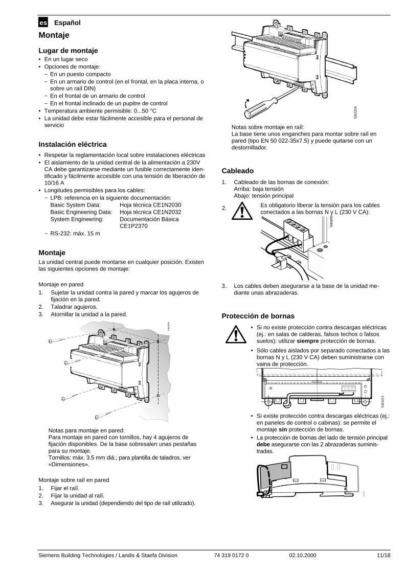
1. Cableado de las bornas de conexión:Arriba: baja tensiónAbajo: tensión principal
2. Es obligatorio liberar la tensión para los cablesconectados a las bornas N y L (230 V CA):
5363
Z03
3. Los cables deben asegurarse a la base de la unidad me-diante unas abrazaderas.
Protección de bornas
• Si no existe protección contra descargas eléctricas(ej.: en salas de calderas, falsos techos o falsossuelos): utilizar siempre protección de bornas.
• Sólo cables aislados por separado conectados a lasbornas N y L (230 V CA) deben suministrarse convaina de protección.
5363
Z13
• Si existe protección contra descargas eléctricas (ej.:en paneles de control o cabinas): se permite elmontaje sin protección de bornas.
• La protección de bornas del lado de tensión principaldebe asegurarse con las 2 abrazaderas suminis-tradas.
536
3Z
07

12/18 02.10.2000 74 319 0172 0 Siemens Building Technologies / Landis & Staefa Division
Puesta en servicio
Manejo y funcionamiento1 2 3 4 5
6 7 8
5363
Z06
ON
1 2
1 Selector RS-232 (selector «2» está inactivo)2 Botón de rearme del módem3 Conector RS-2324 Bornas de conexión para baja tensión5 Botón LPB6 Bornas de conexión para tensión principal7 LED (verde) de funcionamiento8 LED (rojo) de alarmas
LED de funcionamientoEl LED verde indica el estado de funcionamiento de la unidadcentral:• LED iluminado: tensión principal activa• LED parpadea: communicación vía LPB y/o RS-232El LED también está visible cuando se ha protegido la borna.
LED de alarmasEl LED rojo indica el estado de alarmas de la unidad central:• LED apagado: no hay fallo ni alarma• LED iluminado: fallo de uno o varios controladores LPB• LED parpadea: fallo en la unidad centralEl LED también está visible cuando las bornas están protegidas.
Selector RS-232El selector se utiliza para elegir si el puerto RS-232 de la unidad
central va conectado a un módem (posición del selector ) o
directamente a un PC (posición del selector ).
Botón LPBEl botón LPB se utiliza para arrancar la búsqueda, creándose porlo tanto el listado del equipo.Otras opciones para crear el listado del equipo: ver la sección«Puesta en servicio» bajo «Procedimiento» (paso 8).Para completar la búsqueda, el número de equipos incluidos enel listado se puede solicitar en cualquier momento pulsandoligeramente el botón LPB (<0.5 segundos).
Botón de rearme del módemEl botón de rearme del módem se utiliza para reinicializar elmódem. A continuación, la unidad central establecerá conexióncon el centro de control y entregará un informe de estado.
Puesta en servicio• Notas: funcionamiento con un PC: en el caso de fun-
cionamiento directo con un PC vía el puerto RS-232, se nece-sita un null módem entre los 2 equipos.
• Los ajustes que aparecen bajo el apartado 7. pueden rea-lizarse igualmente con antelación.
Procedimiento
1. NO conectar aún la alimentación.
2. Retirar las protecciones de las bornas (si las hubiera).
3. Verificar el cableado de acuerdo con el esquema de lainstalación.
4. Al poner en servicio la unidad, el selector RS-232 debe
posicionarse en (comunicación directa con el PC vía elpuerto RS-232).
5. En caso necesario, sustituir la protección de la borna dellado de la tensión principal.
6. Conectar la alimentación.
7. Los siguientes ajustes deben realizarse con el software demanejo ACS600 vía el puerto RS-232, o con la herramientade servicio ACS69 vía el interfaz de comunicación OCI69vía LPB:− Número de teléfono del centro de control− Número de teléfono de la instalación *− Nombre de la unidad central para las 2 entradas digitales y
para los controladores conectados *− Secuencia del módem para la inicialización de éste *− Velocidad de transmisión en baudios del módem*− Secuencia del módem para el comando de marcación *− Secuencia del módem para el comando del abonado
móvil*− Secuencia del módem para el sufijo del módem *− Secuencia del módem para comando de rearme del
módem** Opcional
8. Crear el listado del equipo. Se hace de la siguiente forma:− Pulsar el botón LPB durante 6 segundos− Con la herramienta de servicio ACS69 vía el interfaz de
comunicación OCI69 vía LPB utilizando la búsqueda, oajustando los parámetros
− Con el software de funcionamiento ACS600 directamentevía el PC y el puerto RS-232 utilizando la búsqueda, oajustando los parámetros.
− Con el software de funcionamiento ACS600 vía módemdesde el centro de control utilizando la búsqueda, o ajus-tando los parámetros.
Notas • La creación de un listado del equipo con laayuda de la búsqueda se recomienda sólo si elnúmero de equipos del LPB no excede elnúmero de equipos que puede conectarse a laOCI611... (1, 5 ó 16, dependiendo del tipo de launidad central)
• Ni la unidad central OCI611... ni el interfaz decomunicación OCI69 alimentan al bus. Para quela comunicación sea posible, debe onectarse almenos un controlador LPB al bus.
9. El número de controladores LPB encontrados viene indicadopor el LED verde. Para cada controlador LPB encontrado, elLED se ilumina brevemente.
10. Otros ajustes de parámetros que deben o pueden hacersetambién vía la herramienta de servicio ACS69 (o el softwarede funcionamiento ACS600) dependen del tipo de instala-ción (ej.: tipo de alarma o fuentes de alarma).
11. Tras la puesta en servicio, la conexión al centro de controlvía módem debe verificarse para evitar llamadas de servicioinnecesarias, derivadas de problemas de comunicación delmódem.Para ese propósito, el selector RS-232 debe posicionarse en
antes de iniciarse la comunicación. Tan pronto como elmódem está conectado a la unidad central, el botón de re-arme del módem puede pulsarse durante 2 segundos.El LED rojo indica cualquier fallo que pueda producirsemientras esté en marcha la comunicación.
12. Sustituir la protección de la borna del lado de baja tensión.
Verificación (final) en la instalación
1. ¿Está el LED verde iluminado (estado de funcionamiento)?2. ¿Está el LED rojo apagado (indicación de alarma)?3. Pulsar el botón LPB brevemente. ¿El número de controla-
dores indicado por el LED verde concuerda con el númerode controladores de la instalación a los que soportará laOCI611...?
4. ¿Funciona correctamente la comunicación con el centro decontrol?
5. ¿Está situado el selector RS-232 en la posición ?

Siemens Building Technologies / Landis & Staefa Division 74 319 0172 0 02.10.2000 13/18
pl Polski
Monta ż
Miejsce monta żu• Pomieszczenie suche• Sposoby montażu:
− W węźle kompaktowym− w szafie sterowniczej (na dzwiach frontowych, na ścianie
wewnętrznej, na szynie montażowej)− na szafie sterowniczej− na pochylonym panelu sterowniczym
• Dopuszczalne temperatury otoczenia 0...50 °C• Należy zapewnić łatwy dostęp w celu serwisowania
Podłączenia elektryczne• Instalacja musi być wykonana zgodnie z lokalnymi przepisami• Na zasilaniu z sieci AC 230 V należy przewidzieć łatwo
dostepny i czytelnie opisany bezpiecznik o prądzie znamiono-wym 10/16 A
• Dopuszczalne długości przewodów:− LPB: zgodnie z nastepującymi dokumentami
Podstawowy opis systemu Karta katalogowa CE1N2030Podstawy projektowania Karta katalogowa CE1N2032Projektowanie Systemu Dokumentacja podstawowa
CE1P2370− RS-232: max. 15 m
ZamocowanieCentrala komunikacyjna może być zamocowana w dowolnejpozycji. Możliwe są następujące warianty montażu:
Montaż naścienny1. Przyłóż urządzenie do ściany i zaznacz miejsca otworów.2. Nawierć otwory.3. Wkręć śruby mocujące.
536
3Z05
Uwagi do montażu naściennego:W podstawie znajdują się cztery otwory do montażunaściennego. Podstawka posiada wyniesioną płaszczyznęmontażową.Śruby: maks. φ3.5 mm; szablon montażowy – patrz«Wymiary».
Montaż na szynie1. Zamocuj szynę montażową.2. Zamocuj urządzenie do szyny.3. Zabezpiecz urządzenie (w zależności od rodzaju szyny).
536
3Z04
Uwagi do montażu na szynie:W podstawie znajduje się zatrzask do szybkiego montażu naszynie (typ EN 50 022-35 x 7.5), który umożliwia równieższybki demontaż przy pomocy śrubokręta.
Okablowanie
1. Zamocuj przewody do listew zaciskowych:Góra: niskie napięcieDół: sieciowe napięcie zasilające
2. Koniecznie należy przewidzieć odciążenienaprężenia przewodów zasilających N oraz L(AC 230 V) !
5363
Z03
3. Kabel powinien być zamocowany do urządzenia przy pomocyzacisku.
Pokrywy ochronne listew zaciskowych
• Jeżeli nie przewidziano zabezpieczeń przedporażeniem prądem elektrycznym (np.pomieszczenia kotłowni, stropy podwieszone),zawsze należy stosować pokrywy ochronne.
• Tylko kable z pojedynczą izolacją na zaciskach N iL (AC 230 V) muszą posiadać osłony izolacyjnemüssen:
5363
Z13
• Jeżeli istnieje zabezpieczenie przed porażeniemprądem elektrycznym (np. szafy sterownicze),montaż bez osłon ochronnych jest dozwolony.
• Osłona ochronna zasilającej listwy zaciskowej musibyć zabezpieczona przy użyciu dwóch opasekzaciskowych dostarczonych z urządzeniem:
536
3Z
07

14/18 02.10.2000 74 319 0172 0 Siemens Building Technologies / Landis & Staefa Division
Uruchomienie
Eksploatacja i obsługa1 2 3 4 5
6 7 8
5363
Z06
ON
1 2
1 Przełącznik RS-232 (przełącznik «2» nie jest wykorzystywany)2 Przycisk zerowania modemu3 Gniazdo RS-2324 Listwa zaciskowa niskiego napięcia5 Przycisk LPB6 Listwa zaciskowa napięcia sieciowego7 Wskaźnik stanu pracy (zielona LED)8 Wskaźnik alarmu (czerwona LED)
Wskaźnik LED stanu pracyZielona dioda LED wskazuje odpowiedni stan pracy urządzenia:• LED świeci: urządzenie jest zasilone napięciem sieciowym• LED pulsuje: komunikacja przez LPB oraz / lub RS-232.Dioda jest widoczna również po nałożeniu pokrywy ochronnej.
Wskaźnik LED alarmuCzerwona dioda LED wskazuje odpowiedni stan błędu:• LED nie świeci: bez błędu i alarmu• LED świeci: błąd jednego lub kilku urządzeń LPB• LED pulsuje: błąd centrali komunikacyjnej LPBDioda jest widoczna również po nałożeniu pokrywy ochronnej.
Przełącznik RS-232Przełącznik RS-232 służy do określenia czy port szeregowyurządzenia podłączony jest do modemu (pozycja przełącznika
) czy bezpośrednio do PC (pozycja przełącznika ).
Przycisk LPBPrzycisk LPB- służy do uruchomienia przeszukiwania w celuutworzenia wewnętrznej listy obsługiwanych urządzeń. Innysposób utworzenia listy: patrz «Uruchomienie», «Procedura»(punkt 8).Po zakończeniu przeszukiwania, liczba urządzeń znajdującychsię na liście może być wywołana przez wciśnięcie przycisku LPB(<0,5 sekund).
Przycisk zerowania modemuPrzycisk zerowania modemu służy do reinicjalizacji modemu. Poreinicjalizacji, centrala komunikacyjna nawiązuje łączność ze stacjąoperatorską i przekazuje raport stanu pracy.
Uruchomienie• Uwagi: Praca bezpośrednia z PC. Dla uzyskania
bezpośredniego połączenia z PC przez port szeregowy RS-232pomiędzy urządzeniami należy zastosować standardowymodem zerowy.
• Nastawy wyszczególnione w punkcie 7 mogą być wykonanezawczasu, przed nawiązaniem komunikacji.
Procedura
1. NIE WŁĄCZAJ jeszcze zasilania.2. Zdejmij pokrywę ochronną, jeżeli została zamontowana.3. Sprawdź czy okablowanie jest zgodne ze schematem.4. Podczas uruchomiania przełącznik RS-232 powinien być
ustawiony w pozycji (bezpośrednia komunikacja z PCprzez port RS-232).
5. Jeżeli jest to wymagane, zamontuj ponownie pokrywęochronną listwy zasilającej.
6. Włącz zasilanie.
7. Przez port RS-232 z programem użytkowym ACS600 (lubprogramu serwisowego ACS69 z interface komunikacyjnymOCI69 poprzez sieć LPB) należy sparametryzowaćnastępujące nastawy:
− numer telefoniczny stacji operatorskiej− numer telefoniczny obiektu *− Nazwę centrali dla 2 wejść cyfrowych i podłączonych
urządzeń− ciąg znaków inicjalizacyjny modemu *− prędkość transmisji modemu *− ciąg znaków polecenia wyboru numeru telefonicznego *− ciąg znaków polecenia przerwania połączenia *− ciąg znaków końcowy modemu *− ciąg znaków polecenia zerowania modemu. *
* Opcja
8. Utwórz listę urządzeń. Można to wykonać w jeden znastępujących sposobów:
− przez wciśnięcie przycisku LPB na 6 sekund− przy użyciu programu serwisowego ACS69 z Interface
OCI69 połączonym poprzez LPB wywołując poleceniasearch run lub ustawiając parametry
− przy użyciu programu ACS600 i połączenie z PC przezzłącze RS-232 wywołując polecenia search run lubustawiając parametry.
− przy użyciu programu ACS600 i połączenie ze stacjąoperatorską poprzez modem, wywołując polecenia searchrun lub ustawiając parametry
Uwaga • Utworzenie listy urządzeń przy użyciu poleceniasearch zalecane jest tylko gdy liczba urządzeńna LPB nie przekracza liczby urządzeń, któremogą być podłączone do OCI611... (1, 5 lub 16w zależności od typu centralki).
• Zarówno centralka OCI611... jak również Inter-face komunikacyjny OCI69 nie zasila sieci. Dlazapewnienia komunikacji, przynajmniej jedenregulator LPB musi być podłączony do sieci.
9. Liczba znalezionych urządzeń LPB sygnalizowana jestzieloną diodą stanu pracy. Dioda zaświeci się tyle razy ileurządzeń LPB zostało znalezionych.
10. Parametryzacja innych nastaw, które mogą lub muszązostać przeprowadzone z oprogramowania serwisowegoACS69 (lub oprogramowania użytkowego ACS600) zależyod typu obsługiwanej instalacji (np. cykl alarmu).
11. Sprawdzenie komunikacji przez modem ze stacjąoperatorską po uruchomieniu jest absolutnie niezbędne wcelu uniknięcia niepotrzebnych wizyt serwisowychspowodowanych brakiem prawidłowej komunikacji.W tym celu, przełącznik RS-232 musi być ustawiony w
położenie przed nawiązaniem komunikacji. Popodłączeniu modemu do centrali komunikacyjnej LPB,należy wcisnąć przycisk zerujący modemu na 2 sekundy.Wskaźnik alarmu (czerwona dioda LED) sygnalizujeewentualne błędy komunikacji.
12. Zamocuj ponownie pokrywę ochronną listwy niskiego napięcia.
Ostateczne sprawdzenie
1. Czy świeci zielona dioda LED (stan pracy)?2. Czy czerwona dioda LED jest wyłączona (wskazanie
alarmu)?3. Wciśnij na chwilę przycisk LPB. Czy sygnalizowana liczba
urządzeń LPB pokrywa się z rzeczywistą liczbą urządzeńLPB jakie obsługuje centralka OCI611?
4. Czy komunikacja ze stacją operatorską odbywa się bezprzeszkód?
5. Czy przełącznik RS-232 ustawiony jest w pozycji ?

Siemens Building Technologies / Landis & Staefa Division 74 319 0172 0 02.10.2000 15/18
cs česky
Montáž
Montážní místo• V suché místnosti• Možnosti montáže:
− kompaktní stanice− rozvaděč (čelní panel, vnitřní stěna, DIN lišta)− rozvodná deska− čelní panel spínacího pultu
• Přípustná teplota okolí je 0...50 °C• Dbejte na snadný přístup k přístroji
Elektrická instalace• Při elektrické instalaci dbejte místních předpisů• Jištění centrály vůči AC 230 V musí být provedeno označenou
a snadno přístupnou pojistkou 10/16 A• Přípustné délky vedení:
− LPB: viz. následující dokumentaceSystém LPB Katalogový list CE1N2030Projektování systému LPB Katalogový list CE1N2032Projektování systému LPB Základní dokumentace
CE1P2370− RS-232: max. 15 m
MontážKomunikační centrálu je možné montovat v libovolné polozes následujícími možnostmi uchycení:
Montáž na zeď1. Přístroj přidržte na zdi a poznačte si otvory pro uchycení2. Vyvrtejte otvory3. Přístroj přišroubujte
536
3Z05
Pokyny pro montáž na zeď:Pro přišroubování jsou k dispozici čtyři otvory.Šrouby: ∅ max. 3,5 mm. Plán pro vyvrtání otvorů viz. odsta-vec «Rozměry»
Montáž na lištu1. Lištu připevněte na stěnu2. Přístroj nasaďte na lištu3. V případě nutnosti přístroj upevněte (podle druhu lišty)
536
3Z04
Pokyny pro montáž na lištu:Sokl má zámek pro montáž na lištu (typ EN 50022-35x7,5).Tento zámek se uvolňuje šroubovákem ve směru šipky.
Zapojení
1. Zapojte připojovací svorky:nahoře: malé napětídole: síťové napětí
2. Vedení svorek N a L (AC 230 V) nesmí býtvystaveno tahu:
5363
Z03
3. Vedení musí být upevněna do spon na krytu soklu
Kryty svorek
• Pokud není zajištěna ochrana proti dotyku (např.kotelny, mezipodlaží a podhledy):Montáž vždy s kryty svorek
• Vedení ke svorkám N a L (AC 230 V) musí býtopatřeno izolační bužírkou:
5363
Z13
• Pokud je zajištěna ochrana proti dotyku (např. veskříňkách nebo rozvaděči):Montáž je možná bez krytů svorek
• Kryt svorek síťového napětí musí být pojištěn dvěmapřibalenými stahovacími pásky:
536
3Z
07

16/18 02.10.2000 74 319 0172 0 Siemens Building Technologies / Landis & Staefa Division
Uvedení do provozu
Ovládání a obsluha
1 2 3 4 5
6 7 8
5363
Z06
ON
1 2
1 RS-232 přepínač (přepínač«2» je bez funkce)2 Tlačítko „Reset modemu“3 RS-232 konektor4 Svorky pro malé napětí5 LPB tlačítko6 Svorky pro síťové napětí7 Indikace provozního stavu (zelená LED dioda)8 Indikace alarmu (červená LED dioda)
Indikace provozního stavuZelená LED dioda zobrazuje provozní stav:• LED dioda svítí: síťové napájení• LED dioda bliká: komunikace LPB a/nebo RS-232Dioda je viditelná také s namontovaným krytem svorek.
Indikace alarmuČervená LED dioda zobrazuje alarmový stav centrály:• LED dioda nesvítí: žádná chyba nebo alarm• LED dioda svítí: chyba jednoho nebo více LPB regulátorů• LED dioda bliká: interní chyba centrályDioda je viditelná také s namontovaným krytem svorek.
RS-232 přepínačPoloha přepínače určuje, zda je centrála spojená s PC přes
modem (nastavení ) nebo přímo (nastavení ).
LPB tlačítkoLPB tlačítko slouží ke startu prohledávání a tím vytvoření inter-ního seznamu přístrojů.Další možnost vytvoření seznamu přístrojů: viz. kapitolu«Uvedení do provozu», odstavec «Postup», krok 8.Po úspěšném prohledání lze kdykoli krátkým stisknutím LPBtlačítka (<0,5 sekund) zjistit počet přístrojů v seznamu.
Tlačítko „Reset modemu“Tlačítko „Reset modemu“ inicializuje modem. Centrála zahájíspojení s řídícím místem a odešle „zprávu o stavu“.
Uvedení do provozu• Pokyny: Při práci s PC: Při přímém spojení RS-232 s PC musí
být vždy použit nulový modem.• Nastavení v kroku 7 mohou být provedena předem.
Postup1. Nezapínejte ještě síťové napětí2. Sejměte kryty svorek, pokud jsou instalovány3. Zkontrolujte zapojení podle schématu4. RS-232 přepínač musí být při uvedení do provozu v poloze
(přímá komunikace přes RS-232 s PC)5. Nasaďte kryt svorek síťového napětí, pokud je instalován6. Zapněte síťové napájení7. Musí být provedena následující nastavení obslužným soft-
warem ACS600 přes RS-232 rozhraní nebo servisním soft-warem ACS69 přes komunikační převodník OCI69 po LPB:− telefonní číslo řídícího místa− telefonní číslo zařízení *− jméno centrály, dvou digitálních vstupů a připojených regu-
látorů *
− inicializační řetězec modemu *− přenosová rychlost (Baud) *− řetězec pro volbu čísla *− řetězec pro zavěšení *− řetězec pro příponu modemu *− řetězec pro reset modemu *
* volitelně
8. Vytvoření seznamu přístrojů. To lze provést:− stisknutím LPB tlačítka na dobu 6 sekund− se servisním softwarem ACS69 přes komunikační pře-
vodník OCI69 po LPB, prostřednictvím prohledávání nebonastavením
− s obslužným softwarem ACS600 přímo přes PC a RS-232,prostřednictvím prohledávání nebo nastavením
− s obslužným softwarem ACS600 přes modem z řídícíhomísta, prostřednictvím prohledávání nebo nastavením
Pokyny • Vytvoření seznamu přístrojů pomocí prohle-dávání se doporučuje jenom v případě, že početpřístrojů na LPB nepřesahuje maximální možnýpočet připojených přístrojů (podle typu centrály1, 5 nebo 16).
• Ani centrála OCI611... ani komunikační pře-vodník nenapájejí Bus. Aby byla komunikacemožná, musí se na Busu nacházet aspoň jedenLPB regulátor.
9. Počet nalezených LPB regulátorů je indikován zelenou LEDdiodou (zobrazení stavu). S každým LPB regulátorem seLED dioda krátce rozsvítí.
10. Další nastavení, která musí příp. mohou být provedena seservisním softwarem ACS69 (příp. obslužným softwaremACS600), jsou závislá na zařízení (např. alarmový cyklus).
11. Modemové spojení s řídícím místem musí být po úsp ěš-ném uvedení do provozu zkontrolováno, aby se předešlopřípadům, kdy z důvodu nefunkční komunikace nebudemožné provést servisní zásah.
Předtím musí být přepnut RS232 spínač do polohy . Popřipojení modemu k centrále se doporučuje stisknout tlačítko„Reset modemu“ na dobu 2 sekund.Chyba při navázání následné komunikace je indikována čer-venou LED diodou (indikace alarmu).
12. Namontujte kryt svorek malého napětí
(Závěrečná)kontrola1. Svítí zelená LED dioda (provozní stav)?2. Je zhasnuta červená LED dioda (indikace alarmu)?3. Stiskněte krátce LPB tlačítko. Odpovídá počet zelenou LED
diodou indikovaných regulátorů počtu regulátorů, které pod-porují OCI611?
4. Pracuje komunikace s řídícím místem správně?
5. Je RS232 spínač v poloze ?

Siemens Building Technologies / Landis & Staefa Division 74 319 0172 0 02.10.2000 17/18
AnschlussschaltplanConnection diagramSchéma de raccordementAansluitschema
Collegamenti elettriciEsquema básico de conexionesSchemat podł ączeńSchéma elektrického p řipojení
N1
L
N
P M MP
P1 M P2 M MB
AC
230
V
P1 P2
DB
2533
A01
P3
LPB
L
N
N1 Zentrale OCI611...P1, P2 Geräte mit potentialfreiem Kontaktausgang für die StörungssignalisierungP3 LPB-Regler, max. 1 / 5 / 16 je nach Zentralentyp
N1 Central unit OCI611...P1, P2 Devices with a potential-free contact output for signaling faultsP3 LPB controller (max. 1, 5 or 16, depending on the type of central unit)
N1 Centrale de communication OCI611…P1, P2 Appareils avec sortie par contact libre de potentiel pour la signalisation de défautsP3 Régulateur sur bus local (max. 1, 5 ou 16 selon le type de la centrale)
N1 Centrale OCI611…P1, P2 Apparaten met potentiaalvrije contactuitgangen voor foutsignaleringP3 LPB-regelaar (max. 1, 5 of 16 afhankelijk van het centraletype)
N1 Unità centrale OCI611...P1, P2 Apparecchi con uscita libera da potenziale per segnale di anomaliaP3 Regolatore LPB (max. 1, 5 o 16, diende dal tipo di unità centrale)
N1 Unidad central OCI611...P1, P2 Equipos con salida de contacto libre de potencial para señalización de fallosP3 Controlador LPB (máx. 1, 5 ó 16, dependiendo del tipo de la unidad central)
N1 Centrala komunikacyjna LPB OCI611...P1, P2 Urządzenia sygnalizacyjne (alarmowe) ze styikiem bezpotencjałowymP3 Urządzenie (regulator) LPB ( max. 1 / 5 / 16 zależnie od typu centralki)
N1 Centrála OCI611P1, P2 Přístroje s bezpotenciálovým výstupem pro signalizaci poruchyP3 LPB regulátor, max. 1 / 5 / 16 podle typu centrály

Siemens Building Technologies / Landis & Staefa Division 74 319 0172 0 02.10.2000 18/18
MaßbilderDimensionsEncombrementsMaatschetsen
DimensioniDimensionesWymiaryRozměry
Ohne KlemmenabdeckungenWithout terminal coversSans couvre-bornesZonder klemafdekkingenSenza i coperchi di protezioneSin protección de bornasBez pokryw ochronnychBez krytu svorek
5363
M01
62
35,3
90
13,9
110
Mit KlemmenabdeckungenWith terminal coversAvec couvre-bornesMet klemafdekkingenCon i coperchi di protezioneCon protección de bornasZ pokrywami ochronnymiS krytem svorek
5363
M02
62 13,9
35,3
120
152
50
12
161
BohrplanDrilling templatePlan de perçageBoorplanDimaPlantilla de taladrosSzablon monta żowy do wiercenia otworówPlán pro vyvrtání otvor ů
100
135
5363
M0
3
Maße in mm Dimensioni i mmDimensions in mm Dimensiones en mmDimensions en mm Wymiary w mmMaten in mm Rozměry v mm
� 2000 Siemens Building Technologies Ltd.