my master of software engineering portfoliomacr.cis.ksu.edu/publications/guillen (embt)...
TRANSCRIPT

MY MASTER OF SOFTWARE ENGINEERING PORTFOLIO
By
Esteban Guillen
B. S., Kansas State University, 2003
A PORTFOLIO
submitted in partial fulfillment of the
requirements for the degree
MASTER OF SOFTWARE ENGINEERING
Department of Computing and Information Sciences College of Engineering
KANSAS STATE UNIVERSITY
Manhattan, KS
2004
Approved by:
Major Professor Dr. Scott DeLoach

ABSTRACT
The EMBT is a set of three tools that were created to support the Cooperative Robotics Simulator research group that is headed by Dr. Scott DeLoach. The three tools consist of an object building tool, a terrain building tool, and an environment building tool. The object building tool provides the ability to create 3D shapes from the primitive shapes provided by Java 3D. The terrain building tool has the ability to create large random surfaces for use in the robot simulator. While the environment building tool combines the results of the object building and terrain builder into one file for the robot simulator to use as the initial state of a simulation run.
ii

TABLE OF CONTENTS Chapter 1. Vision Document ........................................................................................ 1 Chapter 2. Project Plan ................................................................................................. 9 Chapter 3. Architecture Design .................................................................................. 13 Chapter 4. Inspection Checklist.................................................................................. 64 Chapter 5. Component Design.................................................................................... 65 Chapter 6. XML Definition ...................................................................................... 101 Chapter 7. Software Quality Assurance ................................................................... 103 Chapter 8. Test Plan.................................................................................................. 106 Chapter 9. Assessment Evaluation ........................................................................... 111 Chapter 10. User’s Manual......................................................................................... 114 Chapter 11. Project Evaluation................................................................................... 129 References....................................................................................................................... 134
iii

LIST OF FIGURES Figure 1 EMBT Project Overview................................................................................ 2 Figure 2 Critical Use Cases........................................................................................... 3 Figure 3 Project Schedule ........................................................................................... 11 Figure 4 EMB Package View ..................................................................................... 14 Figure 5 EMB Application Package ........................................................................... 14 Figure 6 EMBApplication Class Diagram.................................................................. 14 Figure 7 EMB Controller Package.............................................................................. 15 Figure 8 EMBController Class Diagram .................................................................... 15 Figure 9 EMBBuildingSurfaceMouseHandler Class Diagram................................... 16 Figure 10 EMBObjectPropertiesWindow Class Diagram .......................................... 16 Figure 11 EMB View Package ................................................................................... 16 Figure 12 EMBView Class Diagram .......................................................................... 17 Figure 13 EMBThreeDimensionalView Class Diagram ............................................ 17 Figure 14 EMBXMLView Class Diagram ................................................................. 17 Figure 15 EMBDrawingView Class Diagram ............................................................ 18 Figure 16 EMBTerrainPreview Class Diagram.......................................................... 18 Figure 17 EMBTerrainFinder Class Diagram............................................................. 18 Figure 18 EMBTerrainView Class Diagram .............................................................. 19 Figure 19 EMBObjectPreview Class Diagram........................................................... 19 Figure 20 EMBObjectFinder Class Diagram.............................................................. 20 Figure 21 EMBObjectView Class Diagram ............................................................... 20 Figure 22 EMBBuildingSurface Class Diagram......................................................... 20 Figure 23 EMB Model Package.................................................................................. 21 Figure 24 EMBModel Class Diagram ........................................................................ 21 Figure 25 EMBEnvironment Class Diagram.............................................................. 22 Figure 26 EMBObject Class Diagram ........................................................................ 23 Figure 27 EMBBasicShape Class Diagram ................................................................ 24 Figure 28 EMBBox Class Diagram ............................................................................ 24 Figure 29 EMBCone Class Diagram .......................................................................... 25 Figure 30 EMBSphere Class Diagram........................................................................ 25 Figure 31 EMBCylinder Class Diagram..................................................................... 25 Figure 32 EMBTerrain Class Diagram....................................................................... 26 Figure 33 EMBObjectLibrary Class Diagram ............................................................ 26 Figure 34 EMBTerrainLibrary Class Diagram........................................................... 27 Figure 35 Sequence Diagram for Opening an Environment....................................... 27 Figure 36 Sequence Diagram for Adding a Terrain.................................................... 28 Figure 37 Sequence Diagram for Adding an Object................................................... 28 Figure 38 EOB Package View .................................................................................... 29 Figure 39 EOB Application Package.......................................................................... 29 Figure 40 EOBApplication Class Diagram................................................................. 29 Figure 41 EOB Controller Package ............................................................................ 30 Figure 42 EOBController Class Diagram................................................................... 31 Figure 43 EOBBoxPropertiesWindow Class Diagram............................................... 32 Figure 44 EOBConePropertiesWindow...................................................................... 33
iv

Figure 45 EOBCylinderPropertiesWindow Class Diagram ....................................... 34 Figure 46 EOBFrontMouseHandler Class Diagram................................................... 34 Figure 47 EOBSideMouseHandler Class Diagram..................................................... 35 Figure 48 EOBSpherePropertiesWindow Class Diagram .......................................... 35 Figure 49 EOBTopMouseHandler Class Diagram ..................................................... 35 Figure 50 EOB View Package .................................................................................... 36 Figure 51 EOBView Class Diagram........................................................................... 36 Figure 52 EOBThreeDimensionalView Class Diagram............................................. 37 Figure 53 EOBDrawingView Class Diagram............................................................. 37 Figure 54 EOBXMLView Class Diagram.................................................................. 37 Figure 55 EOBSideDrawingView Class Diagram...................................................... 38 Figure 56 EOBFrontDrawingView Class Diagram .................................................... 38 Figure 57 EOBTopDrawingView Class Diagram ...................................................... 38 Figure 58 EOBObjectPreview Class Diagram............................................................ 39 Figure 59 EOBObjectFinder Class Diagram .............................................................. 39 Figure 60 EOBObjectView Class Diagram ................................................................ 40 Figure 61 EOB Model Package .................................................................................. 40 Figure 62 EOBModel Class Diagram......................................................................... 41 Figure 63 EOBObject Class Diagram......................................................................... 41 Figure 64 EOBBasicShape Class Diagram................................................................. 42 Figure 65 EOBBox Class Diagram............................................................................. 43 Figure 66 EOBCone Class Diagram........................................................................... 44 Figure 67 EOBSphere Class Diagram ........................................................................ 45 Figure 68 EOBCylinder Class Diagram ..................................................................... 46 Figure 69 EOBObjectLibrary Class Diagram............................................................. 46 Figure 70 Sequence Diagram for Moving a Box........................................................ 47 Figure 71 ETB Package View..................................................................................... 48 Figure 72 ETB Application Package .......................................................................... 48 Figure 73 ETBApplication Class Diagram................................................................. 48 Figure 74 ETB Controller Package............................................................................. 48 Figure 75 ETBController Class Diagram ................................................................... 49 Figure 76 ETB View Package..................................................................................... 50 Figure 77 ETBView Class Diagram ........................................................................... 50 Figure 78 ETBThreeDimensionalView Class Diagram ............................................. 51 Figure 79 ETBXMLView Class Diagram .................................................................. 51 Figure 80 ETBDrawingView Class Diagram ............................................................. 51 Figure 81 ETBBuildingSurface Class Diagram.......................................................... 52 Figure 82 ETBTerrainPreview Class Diagram........................................................... 52 Figure 83 ETBTerrainFinder Class Diagram.............................................................. 53 Figure 84 ETBTerrainView Class Diagram ............................................................... 53 Figure 85 ETB Model Package................................................................................... 53 Figure 86 ETBModel Class Diagram ......................................................................... 54 Figure 87 ETBTerrain Class Diagram ........................................................................ 55 Figure 88 ETBTerrainLibrary Class Diagram ............................................................ 55 Figure 89 Sequence Diagram for Modifying the Terrain ........................................... 56 Figure 90 EMB Package View ................................................................................... 66
v

Figure 91 EMBApplication Class Diagram................................................................ 66 Figure 92 EMBController Class Diagram .................................................................. 67 Figure 93 EMBBuildingSurfaceMouseHandler ......................................................... 67 Figure 94 EMBObjectPropertiesWindow Class Diagram .......................................... 68 Figure 95 EMBView Class Diagram .......................................................................... 68 Figure 96 EMBThreeDimensionalView Class Diagram ............................................ 69 Figure 97 EMBXMLView Class Diagram ................................................................. 69 Figure 98 EMBDrawingView Class Diagram ............................................................ 69 Figure 99 EMBTerrainPreview Class Diagram.......................................................... 70 Figure 100 EMBTerrainFinder Class Diagram........................................................... 70 Figure 101 EMBTerrainView Class Diagram ............................................................ 71 Figure 102 EMBObjectPreview Class Diagram......................................................... 71 Figure 103 EMBObjectFinder Class Diagram............................................................ 72 Figure 104 EMBObjectView Class Diagram ............................................................. 72 Figure 105 EMBBuildingSurface Class Diagram....................................................... 72 Figure 106 EMBModel Class Diagram ...................................................................... 73 Figure 107 EMBEnvironment Class Diagram............................................................ 73 Figure 108 EMBObject Class Diagram ...................................................................... 74 Figure 109 EMBBasicShape Class Diagram .............................................................. 75 Figure 110 EMBBox Class Diagram .......................................................................... 75 Figure 111 EMBCone Class Diagram ........................................................................ 76 Figure 112 EMBSphere Class Diagram...................................................................... 76 Figure 113 EMBCylinder Class Diagram................................................................... 76 Figure 114 EMBTerrain Class Diagram..................................................................... 77 Figure 115 EMBObjectLibrary Class Diagram .......................................................... 77 Figure 116 EMBTerrainLibrary Class Diagram......................................................... 78 Figure 117 EOB Package View .................................................................................. 78 Figure 118 EOBApplication Class Diagram............................................................... 79 Figure 119 EOBController Class Diagram................................................................. 79 Figure 120 EOBBoxPropertiesWindow Class Diagram............................................. 80 Figure 121 EOBConePropertiesWindow Class Diagram........................................... 81 Figure 122 EOBCylinderPropertiesWindow Class Diagram ..................................... 82 Figure 123 EOBFrontMouseHandler Class Diagram................................................. 82 Figure 124 EOBSideMouseHandler Class Diagram................................................... 83 Figure 125 EOBSpherePropertiesWindow Class Diagram ........................................ 83 Figure 126 EOBTopMouseHandler Class Diagram ................................................... 83 Figure 127 EOBView Class Diagram......................................................................... 84 Figure 128 EOBThreeDimensionalView Class Diagram........................................... 84 Figure 129 EOBDrawingView Class Diagram........................................................... 85 Figure 130 EOBXMLView Class Diagram................................................................ 85 Figure 131 EOBSideDrawingView Class Diagram.................................................... 85 Figure 132 EOBFrontDrawingView Class Diagram .................................................. 86 Figure 133 EOBTopDrawingView Class Diagram .................................................... 86 Figure 134 EOBObjectPreview Class Diagram.......................................................... 86 Figure 135 EOBObjectFinder Class Diagram ............................................................ 87 Figure 136 EOBObjectView Class Diagram .............................................................. 87
vi

Figure 137 EOBModel Class Diagram....................................................................... 88 Figure 138 EOBObject Class Diagram....................................................................... 88 Figure 139 EOBBasicShape Class Diagram............................................................... 89 Figure 140 EOBBox Class Diagram........................................................................... 90 Figure 141 EOBCone Class Diagram......................................................................... 91 Figure 142 EOBSphere Class Diagram ...................................................................... 92 Figure 143 EOBCylinder Class Diagram ................................................................... 93 Figure 144 EOBObjectLibrary Class Diagram........................................................... 93 Figure 145 ETB Package View................................................................................... 94 Figure 146 ETBApplication Class Diagram............................................................... 94 Figure 147 ETBController Class Diagram ................................................................. 95 Figure 148 ETBView Class Diagram ......................................................................... 95 Figure 149 ETBThreeDimensionalView .................................................................... 96 Figure 150 ETBXMLView Class Diagram ................................................................ 96 Figure 151 ETBDrawingView Class Diagram ........................................................... 97 Figure 152 ETBBuildingSurface Class Diagram........................................................ 97 Figure 153 ETBTerrainPreview Class Diagram......................................................... 98 Figure 154 ETBTerrainFinder .................................................................................... 98 Figure 155 ETBTerrainView Class Diagram ............................................................. 99 Figure 156 ETBModel Class Diagram ....................................................................... 99 Figure 157 ETBTerrain Class Diagram .................................................................... 100 Figure 158 ETBTerrainLibrary Class Diagram ........................................................ 100 Figure 159 Creating a New Object ........................................................................... 115 Figure 160 Selecting a Shape from the Library........................................................ 116 Figure 161 Adding a Cone Shape ............................................................................. 117 Figure 162 Cone Properties Windw.......................................................................... 118 Figure 163 Modifying a Cone................................................................................... 119 Figure 164 Viewing the Cone in 3D......................................................................... 120 Figure 165 Creating a New Terrain .......................................................................... 121 Figure 166 Modifying a Terrain ............................................................................... 122 Figure 167 Viewing the Terrain in 3D...................................................................... 123 Figure 168 Adding a Terrain from the Library......................................................... 124 Figure 169 Creating a New Envirnment Model........................................................ 125 Figure 170 Selecting a Object and Terrain ............................................................... 126 Figure 171 Object Properties Window ..................................................................... 126 Figure 172 Viewing an Environment in 3D.............................................................. 127 Figure 173 Zooming-in from the 3D View............................................................... 128 Figure 174 Phase Time Breakdown.......................................................................... 131 Figure 175 Phase 1 Breakdown ................................................................................ 131 Figure 176 Phase 2 Breakdown ................................................................................ 132 Figure 177 Phase 3 Breakdown ................................................................................ 132
vii

LIST OF TABLES Table 1 Work Breakdown Structure ........................................................................... 11 Table 2 Technical Inspection Checklist ...................................................................... 64 Table 3 Test Case Result Summary .......................................................................... 111 Table 4 Project Duration........................................................................................... 130
viii

Chapter 1. Vision Document
Introduction
Motivation The concept for the Environment Model Building Tool (EMBT) was driven from the need to dynamically build 3D graphical environment models for the Cooperative Robotics Simulator (CRS). The original CRS hard coded the environment model and had no way to store and reuse the environment models. The EMBT will be an independent tool that allows the user to interactively create and save graphical 3D environment models for the CRS to use.
Cooperative Robotics Simulator The CRS is a new research group at Kansas State University and is headed by Dr. DeLoach. The purpose for creating the group was to build a cooperative robotics simulator that could simulate a large number of autonomous robots working in a virtual environment. The CRS group is currently broken up into five components; Environment Simulator, Simulator Control Panel, 3D Environment Display, Environment model Building Tool, and Robot Simulator.
Environment Simulator The Environment Simulator is the central component of the entire system. It is responsible for keeping track of the state of the virtual environment, including each robot. The Environment Simulator is also the main interface of the EMBT.
Simulator Control Panel The Simulator Control Panel will connect to the Environment Simulator to monitor and control the current simulation.
3D Environment Display The 3D Environment Display will be used to display the virtual environment in 3D. The 3D Environment Display will get all its viewing information from the Environment Simulator.
Environment Model Building Tool The Environment Model Building Tool will be used to create 3D environment models for the Environment Simulator. The models will be in the form of a XML file.
Robot Simulator The Robot Simulator will simulate the actions of various kinds of robots. It will communicate with the Environment Simulator to update sensor readings and location changes.
1
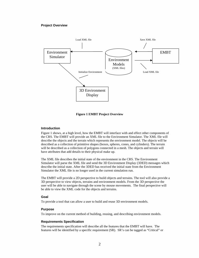
Project Overview
Figure 1 EMBT Project Overview
Introduction Figure 1 shows, at a high level, how the EMBT will interface with and effect other components of the CRS. The EMBT will provide an XML file to the Environment Simulator. The XML file will describe the objects and the terrain which represents the environment model. The objects will be described as a collection of primitive shapes (boxes, spheres, cones, and cylinders). The terrain will be described as a collection of polygons connected in a mesh. The objects and terrain will have attributes that add details to their physical make up. The XML file describes the initial state of the environment in the CRS. The Environment Simulator will parse the XML file and send the 3D Environment Display (3DED) messages which describe the initial state. After the 3DED has received the initial state from the Environment Simulator the XML file is no longer used in the current simulation run. The EMBT will provide a 2D perspective to build objects and terrains. The tool will also provide a 3D perspective to view objects, terrains and environment models. From the 3D perspective the user will be able to navigate through the scene by mouse movements. The final perspective will be able to view the XML code for the objects and terrains.
Goal To provide a tool that can allow a user to build and reuse 3D environment models.
Purpose To improve on the current method of building, reusing, and describing environment models.
Requirements Specification The requirements specification will describe all the features that the EMBT will have. The features will be identified by a specific requirement (SR). SR’s can be tagged as “Critical” or
Environment Simulator
Environment Models (XML files)
EMBT
Load XML file Save XML file
Initialize Environment Load XML file
3D Environment Display
2

“Future”. Critical SR’s are one that are considered most important and will be the focus during implementation. Future SR’s are one that are not vital for the system to run and will be implemented if time permits, otherwise a future developer will implement them.
Critical Use Cases
Figure 2 Critical Use Cases
3

Use Case: Build Environment Models Description: This use case describes constructing the environment model from a 2D perspective. Includes: Import Object(s), Import Terrain(s) Pre-Conditions: There must be environment objects and environment terrains saved to disk. The user is in the environment model building mode. Details: The user will build environment models from environment objects and environment terrains. The user will have a window, to place environment objects and environment terrains, for building the environment model. The user will select either an object or terrain from a preview window and place it on the window surface. There will be a preview window for both objects and terrains. The object preview window will list all available objects in a hierarchical structure and allow the user to select an object to preview. A selected object will be displayed in 3D on the preview window. The selected object can then be place in the model building window. The terrain preview window will function in same way as the object preview window. Once the object or terrain has been placed on the window surface it can be resized, moved, and rotated with the use of the mouse. Each object and terrain will also have its own properties window that the user can pull up to modify attributes values for the object or terrain. The user will also be able to zoom in and out of the window. Objects and terrains that are modified from the properties window can be saved as new objects and terrains. A group of objects can also be selected and saved as a new object (for example a group of houses could be saved as a city block). Post-Conditions: An environment model is constructed and is ready to be saved. Specific Requirements:
SR1 [Critical Requirement] The system shall provide a 2D graphical user interface to build environment models.
SR2 [Critical Requirement] The system will allow the user to build environment models from environment objects and environment terrains.
SR3 The system will allow the user to specify camera locations in the environment model. There will be a default camera with a top down view pointing a location (0,0,0).
SR4 The system will allow the user to specify light source locations in the environment model. There will be a default light source to represent the sun.
SR5 The system will provide a zoom-in and zoom-out feature for the environment model building graphical user interface.
SR5.1 The system will provide an object preview window for listing and viewing available objects from the object database.
SR5.2 The system will provide a terrain preview window for listing and viewing available terrains from the object database.
SR5.3 The object preview window will allow the user to select an object from a list and view it in 3D.
4

SR5.4 The terrain preview window will allow the user to select a terrain from a list and view it in 3D.
SR5.5 [Future Requirement] The system will allow the user to select objects from the window surface and save the group as a new object. The object will be saved to the object database.
SR5.6 [Future Requirement] The system will allow the user to save objects, which have been modified from the properties window, as new objects to the object database.
SR5.7 [Future Requirement] The system will allow the user to save terrains, which have been modified from the properties window, as new terrain objects to the terrain database.
Use Case : Build Environment Terrains Description: This use case describes building environment terrains from a 2D perspective. Includes: Modify Elevation, Set Terrain Properties, Save to Terrain Database Pre-Conditions: The user is in the environment terrain building mode. Details: The user will be provided with a window to create the terrain. The window will initially have a flat surface. The user will be able to select regions of the surface and modify the elevation for the selected regions. Modifying the elevation will be controlled by mouse actions. A color coding will be used to provide visual feedback about the elevation changes. Black will represent the lowest elevations and white will represent the highest elevations. The user will be able to specify different terrain properties, from a properties window, for a selected region. The properties will include things such as grassy surfaces, rocky surfaces, water surfaces, sand surfaces, forest surfaces, and dirt surfaces. The user will also be able to zoom in and out of the window. The user will be able to save the terrain to the terrain database. Post-Conditions: When the user is done creating the terrain it saved to the terrain database. Specific Requirements:
SR6 [Critical Requirement] The system shall provide a 2D graphical user interface to build environment terrains
SR7 The system will allow the user to build environment terrains by selecting regions of an initially flat surface and then modifying the elevation.
SR8 [Critical Requirement] The system will allow the user to save environment terrains to the terrain database.
SR9 The system shall provide a property window for each section of an environment terrain. The property window will allow the user to modify the physical attributes of the environment terrain.
SR10 Physical attributes for environment terrains will include color, dimensions, reflection properties, location, friction, temperature and the type of surface. The type of surface will include grassy surfaces, rocky surfaces, water surfaces, sand surfaces, forest surfaces, and dirt surfaces
5
SR11 The system will provide a zoom-in and zoom-out feature for the environment terrain building graphical user interface.
Use Case: Build Environment Objects Description: This use case describes building environment objects in a 2D perspective. Includes: Draw Primitive(s), Use Saved Object(s), Resize, Move, Rotate, Set Object Properties, Save To Object Database. Pre-Conditions: The user is in the object building mode. Details: The user will be provided with a window to create the object. Environment objects will be constructed from cube, cone, cylinder, and sphere primitive shapes as well as existing objects. The user will draw primitive shapes on the window. The user will also be able to use an existing object from the database of objects and place it in the window. An existing object will have all its primitive shapes placed in the window when selected. Once the shapes are drawn on the window the user can resize, move, and rotate them with the mouse. Each primitive shape will have a properties window that the user can use to modify attribute values of the shape. The user will also be able to zoom in and out of the window. Post-Conditions: When the user is done creating the new object it can be saved to disk. Specific Requirements:
SR12 [Critical Requirement] The system shall provide a 2D graphical user interface to build environment objects.
SR13 [Critical Requirement] The system will allow the user to build environment objects from the following Java 3D primitive shapes; Cones, Spheres, Cylinders, and Boxes.
SR13.1 The system will allow the user to build environment objects from existing objects in the object database. When an existing object is selected its primitive shapes will be placed in the window.
SR14 [Critical Requirement] The system will allow the user to save environment objects the object database.
SR15 The system shall provide a property window for each environment object. The property windows will allow the user to modify the physical attributes of the environment object.
SR16 Physical attributes for environment objects will include weight, color, dimensions, reflection properties, temperature, location, friction, and rotations.
SR17 The system will allow the user to resize environment objects with the mouse.
SR18 The system will allow the user to move the location of environment objects with the mouse.
SR18.1 [Future Requirement] The system will allow the user to rotate an object with the mouse.
6

SR19 The system will provide a zoom-in and zoom-out feature for the environment object building graphical user interface.
Use Case: View in 3D Description: This use case describes viewing a model, object or terrain in 3D. Pre-Conditions: There user must be in model building, object building or terrain building mode. Details: The user will be provided with a window for viewing in 3D. The window will provide a 3D representation of the 2D building perspective. The user will be able to rotate the scene about the x, y, and z axis with mouse movements. The user will also be able to zoom in and out with mouse and keyboard actions. Post-Conditions: None Specific Requirements:
SR20 The system will allow the user to view environment objects from a 3D perspective.
SR21 The system will allow the user to view environment terrains from a 3D perspective.
SR22 The system will allow the user to view environment models from a 3D perspective.
SR23 The system will allow the user to navigate through 3D perspectives with mouse movements.
Use Case: Save Model To XML Description: This use case describes exporting XML representations of the environment model. Pre-Conditions: There must be an environment model to export. Details: There will be a menu item to either export or import the environment model. Both imported and exported files will be in XML format and will describe the objects and terrains included in the environment. When exporting an environment model the user will be provided with a window to name the XML file. When importing an environment model the user will be provided with a widow to select a XML file. Post-Conditions: There will be a new file saved to disk. Specific Requirements:
SR24 [Critical Requirement] The system will allow the user to save the environment model to an XML format.
SR25 [Critical Requirement] The system will be required to comply with a DTD for the XML file produced when saving the environment model. The Environment Simulator will determine the DTD specification. The DTD file will continually be evolving as the project progresses. A sample of the current DTD will be provided in the DTD Description Document.
Use Case: Load Saved Model Description: This use case describes loading environment models. Pre-Conditions: There must be an environment model to load. Details: There will be a menu item to import the environment model. Imported files will be in XML format and will describe the objects and terrains included in the environment. When importing an environment model the user will be provided with a widow to select a XML file. Post-Conditions: The user will be in the environment building mode as described in Use Case 1.
7

Specific Requirements:
SR26 [Critical Requirements] The system will allow the user to open and edit saved environment models.
Use Case: Import Object(s) Description: This use case describes loading environment objects into the environment model. Includes: Search Object Database. Pre-Conditions: There must be environment objects saved to disk. At a minimum the Java 3D primitive shapes (cone, box, sphere, and cylinder) will be provide. The user must be in environment building mode. Details: The user will select environment objects from a menu. The user can then draw the environment object on the window provided by Use Case 1. Post-Conditions: The object will be added to the environment model. Specific Requirements: SR7 from use case 1.
Use Case: Import Terrain(s) Description: This use case describes loading environment terrains into the environment model. Includes: Search Terrain Database. Pre-Conditions: There must be environment terrains saved to disk. At a minimum a flat surface will be provided. The user must be in environment building mode. Details: The user will select environment objects from a menu. The user can then draw the environment terrain on the window provided by Use Case 1. Post-Conditions: The object will be added to the environment model. Specific Requirements: SR7 from use case 1
Assumptions The user has a JVM 1.3.1 or later and Java 3D 1.3.1 or later installed. The user should have a graphics card that supports OpenGL. The user will need a 1.6GHz processor or better. The user will need 512MB of system memory.
Constrains The DTD file provided by the Environment Simulator will determine the structure of the XML file produced when saving the environment model. Java is not the most efficient language for 3D and 2D graphics, so speed will be a constant issue. Building 3D objects in a 2D view has limited capabilities.
Environment The EMBT will be written in Java and compiled with the JDK 1.4.2 and Java 3D 1.3.1. Eclipse will be the development environment. The EMBT will be tested under Windows XP, Linux, and Solaris. Version control will be handled by CVS.
8

Chapter 2. Project Plan
Task Breakdown
Inception Phase The inception phase is focused on defining the requirements for the project. A vision document will be developed to provide an overview of the project and to document requirements. A project plan will be developed to provide an estimate of the work load and give a schedule for completing project tasks. A software quality assurance plan will be created to describe the required documentation and the steps taken to ensure a quality product is produced. The development of a prototype will also take place during the inception phase. The prototype is designed to show the feasibility of the project. The inception phase is complete when the developer presents all required documentation and the committee members approve.
Elaboration Phase The elaboration phase is focused on design issues. Revisions of documents from the inception phase will be completed at the committee members’ request. A formal requirements specification will be developed for a component of the project. An architecture design will be developed to describe the system. A test plan will be developed to describe how testing will be performed and reported. The technical inspectors will review the architecture design and report on their findings. Finally another prototype will be developed to demonstrate some of the more challenging product features. The elaboration phase is complete when the developer presents all required documentation and the committee members approve.
Production Phase The production phase is focused on implementation and testing. The developer will produce a component design to describe the system at a low level. Most the developer’s time will be spent on developing the code. The code will be well documented and unit testing will be performed. The code will be tested to ensure all the requirements are meet. All tests results will be evaluated and documented. The developer will also write a complete user manual which describes how to install and use the software. The production phase is complete when the developer presents all required documentation, demonstrates the final project, and the committee members approve.
Architecture Elaboration Plan The following items must be complete before the second presentation is made.
Revision of Vision Document Changes to the requirements or project scope since the first presentation must get updated in the vision document.
Revision of Project Plan Changes to the schedule of the project must be updated in the project plan. The time and cost estimates will be revised using a bottom-up approach based on project progress. There will also be an Implementation Plan section added to the Project Plan document.
9

Architecture Design The developer must have a strong understanding about how to build the system. All interfaces will be defined and UML diagrams will be used.
Development of Prototype The prototype will demonstrate the critical requirements (defined in the Vision document) to demonstrate they can be implemented.
Test Plan A test plan will document the tests that are to be performed to ensure the requirements are meet.
Formal Technical Inspections The architecture design will be inspected by Cem Oguzhan and Kevin Sung. Both inspectors will produce a report on their inspection findings.
Formal Requirements Specification At least one part of the project will be formally specified using a methodology such as OCL. I will formally specify the relationship between the terrain and objects. For example I will specify that objects should rest on surface of the terrain instead of floating in mid air. Also I will specify some uniqueness properties for the database part of the system.
Cost Estimate (based on current progress) The project is now at the end of the Elaboration Phase. According to the time log I have spent 152 hours on the project. I have spent 90 hours coding/debugging/testing and 62 hours documenting. The prototype for the project has 1200 SLOC and it implements about 25% of the required features. From this data the following metrics can be calculated. 1200 SLOC / 90 hours = 13.3 SLOC/hour (productivity) 1200 SLOC / .25 = 4800 SLOC (total SLOC) The above calculations show that my productivity was 13.3 SLOC/hour and that there is about 4800 SLOC required for the project. There will be 3600 SLOC left for development. The following calculation estimates how much time will be required for the rest of the code development. (3600 SLOC)/ 13.3 SLOC/hour = 270.7 hours (total remaining development time) (270.7 hours) / 7 hours/day = 39 days I would estimate that the remaining documentation will take about 56 hours (8 days). This would make the total time required for the rest of the project about 47 days. At a high level I will break down those days as follows: Coding/Debugging – 30 days Testing – 9 days Documentation – 8 days The Implementation Plan will provide a detailed WBS.
10

The Gantt chart below gives a schedule for the remainder of the project.
Figure 3 Project Schedule
Implementation Plan
Deliverables The following are the deliverables for presentation three. Action Items User Manual Component Design Source Code Assessment Evaluation Project Evaluation References Formal Technical Inspection Letters
Work Breakdown Structure The follow table breaks down the deliverables into tasks and lists the completion criteria and cost for each task.
Table 1 Work Breakdown Structure
Deliverable Tasks Completion Criteria
Time Cost
Develop EOB Application Package
Executable code June 10 1 day Source Code
Develop EOB Controller Package
Executable code June 10 – June 16 5 days
11

Develop EOB Model Package
Executable code June 11 – June 18 6 days
Develop EOB View Package
Executable code June 11 – June 25 11 days
Develop ETB Application Package
Executable code June 18 1 day
Develop ETB Controller Package
Executable code June 21 – June 23 3 days
Develop ETB View Package
Executable code June 21 – June 25 5 days
Develop ETB Model Package
Executable code June 22 – June 28 5 days
Develop EMB Application Package
Executable code June 30 1 day
Develop EMB Controller Package
Executable code July 1- July 6 4 days
Develop EMB View Package
Executable code July 5 – July 14 8 days
Develop EMB Model Package
Executable code July 6 – July 15 8 days
Run Test Cases All test cases are run
July 16 – July 21 4 days Assessment Evaluation
Document Results All results from each test case have been evaluated and documented
July 22 – July 28 9 days
Action Items
Document Effort in Completing Action Items
All action items from presentation 2 have been addressed
July 29 1 day
Component Design
Document EOB Design
All major features of the EOB have been documented with UML and JavaDoc
July 30 1 day
12

Document ETB All major features of the ETB have been documented with UML and JavaDoc
August 2 1 day
Document EMB All major features of the EMB have been documented with UML and JavaDoc
August 3
Document How to Install
Approved by Major Professor
August 3 1 day
Document How to use EOB
Approved by Major Professor
August 4 1 day
Document How to Use ETB
Approved by Major Professor
August 5 1 day
User Manuel
Document How to Use EMB
Approved by Major Professor
August 6 1 day
Document Usefulness of Methodologies
Approved by Major Professor
August 6 1 day
Document Accuracy of Estimates
Approved by Major Professor
August 7- August 8
2 days
Project Evaluation
Document Usefulness of Reviews
Approved by Major Professor
August 9 1 day
References All References Documented
Approved by Major Professor
August 9 1 day
Formal Technical Inspection Letters
Received Letters from Technical Inspectors
Approved by Major Professor
August 9 1 day
Chapter 3. Architecture Design
Introduction This document will provide brief descriptions and class diagrams of the applications and classes for the EMBT.
13

Environment Model Builder The Environment Model Builder is a graphical tool to create an environment from a terrain and objects. The tool will have a building surface to place the terrain and objects. The user will be able to move the objects to the desired location. There will also be a three dimensional view to observer what the terrain and objects look like in 3D. The following sections will describe the different packages of the Environment Model Builder in detail.
Package View
EMB Application
EMB Controller
EMB View
EMB Model
Figure 4 EMB Package View
Application Package
EMBApplication
Figure 5 EMB Application Package
Class Descriptions and Diagrams
EMBApplication This class is just intended to have the main method for this program and create the EMBController and set it visible.
Figure 6 EMBApplication Class Diagram
14

Controller Package
EMBObjectPropertiesWindow
EMBController EMBBuildingSurfaceMouseHandler
Figure 7 EMB Controller Package
Class Descriptions and Diagrams
EMBController This class is the main frame of the application. It will handle all the menu item actions. It is responsible for loading files, saving files to disk, and saving EMBEnvironments to the library.
Figure 8 EMBController Class Diagram
EMBBuildingSurfaceMouseHandler This class is responsible for handling mouse events for the building surface. In particular it will wait for mouse clicks and determine if one of the objects was clicked on. If an object is clicked on it will provide a properties window for that object.
15

Figure 9 EMBBuildingSurfaceMouseHandler Class Diagram
EMBObjectPropertiesWindow This class provides the properties window for an object. It will provide controls to move the object to a new location.
Figure 10 EMBObjectPropertiesWindow Class Diagram
View Package
EMBBuildingSurface
EMBThreeDimensionalView
EMBView
1+threeD
1EMBXMLView1
+xml
1
EMBTerrainFinder
EMBTerrainPreview
1+finder 1
EMBTerrainView
1+view 1
EMBDrawingView
1+builder 1
1+canvas 1
1 +terrainPrev1
EMBObjectFinder
EMBObjectPreview1+objectPrev
1
1+finder
1
EMBObjectView
1+view
1
Figure 11 EMB View Package
Class Descriptions and Diagrams
EMBView This class is a container for the EMBThreeDimensionalView, EMBDrawingView, and EMBXMLView.
16

Figure 12 EMBView Class Diagram
EMBThreeDimensionalView This class will show the three dimensional view of the current EMBEnvironment. From this view the user will be able to view the EMBEnvironment from any angle.
Figure 13 EMBThreeDimensionalView Class Diagram
EMBXMLView This class is responsible for displaying the XML definition of the current EMBEnvironment. The XML will represent the contents that will be saved to disk.
Figure 14 EMBXMLView Class Diagram
17

EMBDrawingView This class is a container for the EMBBuildingSurface, EMBTerrainPreview, EMBObjectPreview.
Figure 15 EMBDrawingView Class Diagram
EMBTerrainPreview This class is a container for the EMBTerrainFinder and EMBTerrainView. It will also add the currently selected EMBTerrain to the EMBModel.
Figure 16 EMBTerrainPreview Class Diagram
EMBTerrainFinder This class is responsible for providing a list of all available EMBTerrains in the EMBTerrainLibrary for the user to select.
Figure 17 EMBTerrainFinder Class Diagram
18
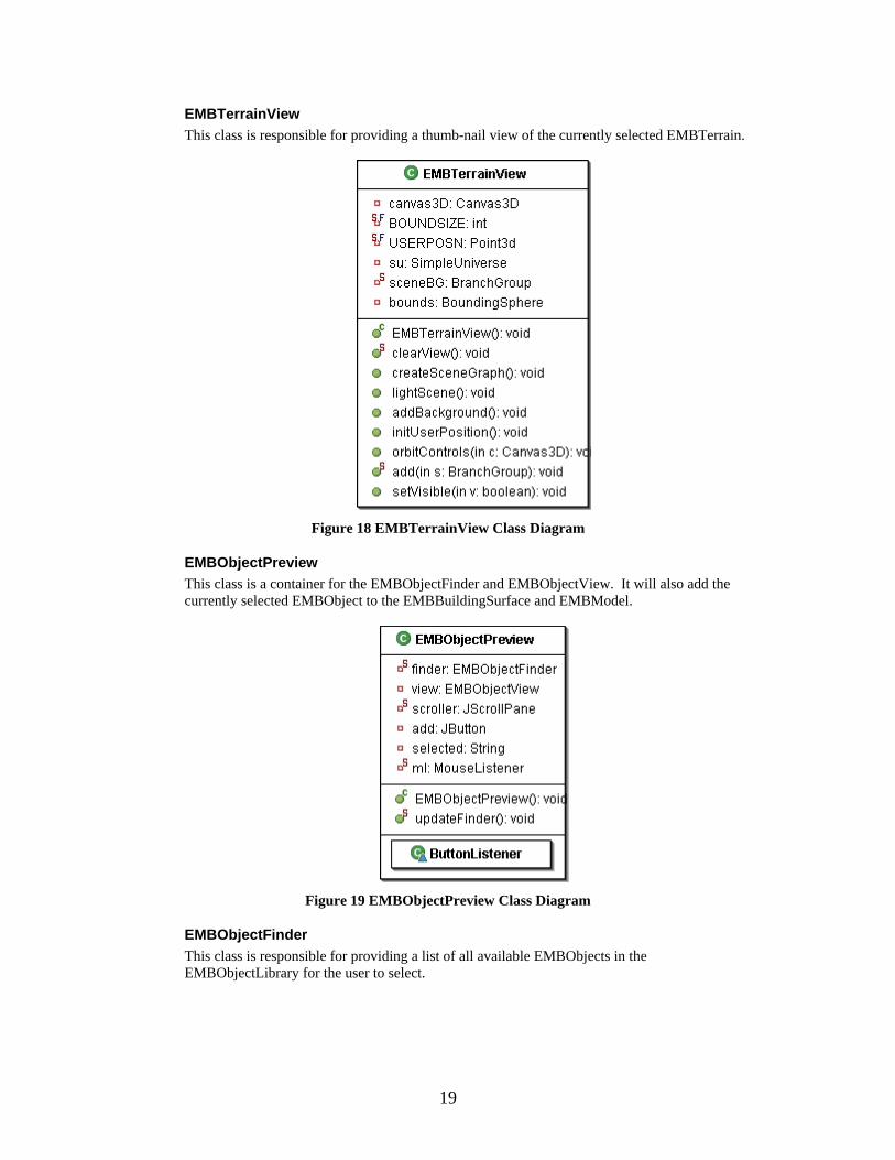
EMBTerrainView This class is responsible for providing a thumb-nail view of the currently selected EMBTerrain.
Figure 18 EMBTerrainView Class Diagram
EMBObjectPreview This class is a container for the EMBObjectFinder and EMBObjectView. It will also add the currently selected EMBObject to the EMBBuildingSurface and EMBModel.
Figure 19 EMBObjectPreview Class Diagram
EMBObjectFinder This class is responsible for providing a list of all available EMBObjects in the EMBObjectLibrary for the user to select.
19

Figure 20 EMBObjectFinder Class Diagram
EMBObjectView This class is responsible for providing a thumb-nail view of the currently selected EMBObject.
Figure 21 EMBObjectView Class Diagram
EMBBuildingSurface This class is responsible for displaying the top 2-D view of the current EMBEnvironment. From this view the user will be able arrange the objects and terrains that have been added to it. This view will also allow for removal of terrains and objects.
Figure 22 EMBBuildingSurface Class Diagram
20

Model Package
EMBCone
EMBCylinder
EMBSphere
EMBBox
EMBObjectLibrary
EMBBasicShape
EMBEnvironmentLibrary
EMBModel EMBObject
11..n 1
+objects
1..n1
1..n
1
+shapes1..n
EMBEnvironment
1
1..n
1
+environments 1..n
1 11
+environment
1 n
1..n
n +objects
1..n
EMBTerrainLibrary
EMBTerrain
n
1
n
+terrain 1
1
1..n
1
+terrains 1..n
Figure 23 EMB Model Package
Class Descriptions and Diagrams
EMBModel This class is responsible for holding the current EMBEnvironment that is being built and making it available to other classes.
Figure 24 EMBModel Class Diagram
EMBEnvironment This class represents the current environment that is being built. It will be composed of numerous EMBTerrains and EMBObjects. It will also be responsible for building its XML definition.
21

Figure 25 EMBEnvironment Class Diagram
EMBObject This class is a collection of EMBBasicShapes that are to be used in the EMBEnvironment. It is also responsible for building its XML definition.
22

Figure 26 EMBObject Class Diagram
EMBBasicShape This class is the super class for the primitive shapes; EMBBox, EMBCone, EMBSphere, and EMBCylinder. It is responsible for building the XML definition for the primitive shapes.
23

Figure 27 EMBBasicShape Class Diagram
EMBBox This class represents a box shape. It holds all the information necessary to represent a three dimensional box shape.
Figure 28 EMBBox Class Diagram
24

EMBCone This class represents a cone shape. It holds all the information necessary to represent a three dimensional cone.
Figure 29 EMBCone Class Diagram
EMBSphere This class represents a sphere shape. It holds all the information necessary to represent a three dimensional sphere.
Figure 30 EMBSphere Class Diagram
EMBCylinder This class represents a cylinder shape. It holds all the information necessary to represent a three dimensional cylinder.
Figure 31 EMBCylinder Class Diagram
EMBTerrain This class represents a terrain for the environment. It will consist of an elevation map and a collection of coordinates. The elevation map will specify the height of all the desired locations. The terrain will be represented by strips of triangles.
25

Figure 32 EMBTerrain Class Diagram
EMBObjectLibrary This class will hold all the EMBObjects that are saved to the object library.
Figure 33 EMBObjectLibrary Class Diagram
EMBTerrainLibrary This class will hold all the EMBTerrains that are saved to the object library.
26

Figure 34 EMBTerrainLibrary Class Diagram
Sequence Diagrams The following sequence diagrams show some of the main functions that the Environment Model Builder will perform
Opening a Saved Environment The following sequence diagram show the sequence of actions involved in reading in a saved environment.
: User : EMBController
: EMBModel
open
parseXML
addObject
addTerrain
Figure 35 Sequence Diagram for Opening an Environment
27

Adding a Terrain to the Building Surface The following sequence diagram shows searching for a terrain and then adding it to the building surface.
: User : EMBTerrainFinder : EMBObjectView : EMBTerrainPreview : EMBModel : EMBTerrainLibrary
double click
clearView
add
click add button
addToModel
addTerrain
Figure 36 Sequence Diagram for Adding a Terrain
Adding a Object to the Building Surface The following sequence diagram shows searching for an object and then adding it to the building surface.
: User : EMBObjectFinder : EMBObjectView : EMBObjectPreview : EMBModel : EMBObjectLibrary
double click
clearView
addCube
click add button
addToModel
addObject
Figure 37 Sequence Diagram for Adding an Object
Environment Object Builder The Environment Object Builder is a graphical tool for building complex shapes/object from primitive shapes. The tool will have three drawing surfaces representing a two dimensional view from the top, side, and front. The user will be able to move and resize the primitive shape from any of the three drawing surfaces. There will also be a three dimensional view provided to observe the created object in 3D. Finally there will be a XML view to show the textual
28

description of object. The following sections will describe the packages of the Environment Object Builder
Package View
EOB Application
EOB Controller
EOB View
EOB Model
Figure 38 EOB Package View
Application Package
EOBApplication
Figure 39 EOB Application Package
Class Descriptions and Diagrams
EOBApplication This class is just intended to have the main method for this program and create the EOBController and set it visible.
Figure 40 EOBApplication Class Diagram
29

Controller Package
EOBController EOBBoxPropertiesWindow
EOBConePropertiesWindow
EOBCylinderPropertiewWindow
EOBSpherePropertiesWindow
EOBFrontMouseHandler
EOBSideMouseHandler
EOBTopMouseHandler
Figure 41 EOB Controller Package
Class Descriptions and Diagrams
EOBController This class is the main frame of the application. It will handle all the menu item actions. It is responsible for loading files, saving files to disk, and saving EOBObjects to the library.
30

Figure 42 EOBController Class Diagram
EOBBoxPropertiesWindow This class provides a JDialog window with controls for modifying a EOBBox.
31

Figure 43 EOBBoxPropertiesWindow Class Diagram
EOBConePropertiesWindow This class provides a JDialog window with controls for modifying a EOBCone.
32

Figure 44 EOBConePropertiesWindow
EOBCylinderPropertiesWindow This class provides a JDialog window with controls for modifying a EOBCylinder.
33

Figure 45 EOBCylinderPropertiesWindow Class Diagram
EOBFrontMouseHandler This class is responsible for handling mouse events for the front building surface. In particular it will wait for mouse clicks and determine if one of the objects was clicked on. If an object is clicked on it will provide a properties window for that object.
Figure 46 EOBFrontMouseHandler Class Diagram
EOBSideMouseHandler This class is responsible for handling mouse events for the side building surface. In particular it will wait for mouse clicks and determine if one of the objects was clicked on. If an object is clicked on it will provide a properties window for that object.
34

Figure 47 EOBSideMouseHandler Class Diagram
EOBSpherePropertiesWindow This class provides a JDialog window with controls for modifying a EOBSphere.
Figure 48 EOBSpherePropertiesWindow Class Diagram
EOBTopMouseHandler This class is responsible for handling mouse events for the top building surface. In particular it will wait for mouse clicks and determine if one of the objects was clicked on. If an object is clicked on it will provide a properties window for that object.
Figure 49 EOBTopMouseHandler Class Diagram
35

View Package
EOBObjectFinder EOBObjectView
EOBFrontDrawingView
EOBObjectPreview
1 +finder1 1+view 1 EOBSideDrawingView
EOBTopDrawingView
EOBThreeDimensionalView
EOBDrawingView1
+front
1
1+preview
1
1 +side1
1+top 1
EOBView
1+threeD
1
1+canvas 1
EOBXMLView
1
+xml
1
Figure 50 EOB View Package
Class Descriptions and Diagrams
EOBView This class is a container for the EOBThreeDimensionalView, EOBDrawingView, and EOBXMLView.
Figure 51 EOBView Class Diagram
EOBThreeDimensionalView This class will show the three dimensional view of the current EOBObject. From this view the user will be able to view the EOBObject from any angle.
36

Figure 52 EOBThreeDimensionalView Class Diagram
EOBDrawingView This class is the container for the EOBTopDrawingView, EOBSideDrawingView, EOBFrontDrawingView, and EOBObjectPreview.
Figure 53 EOBDrawingView Class Diagram
EOBXMLView This class is responsible for displaying the XML definition of the current EOBObject. The XML will represent the contents that will be saved to disk.
Figure 54 EOBXMLView Class Diagram
37

EOBSideDrawingView This class is responsible for providing a drawing surface for EOBBasicShapes. This view will represent the side view. The user will be able to move and change the properties of the EOBBasicShapes from this view.
Figure 55 EOBSideDrawingView Class Diagram
EOBFrontDrawingView This class is responsible for providing a drawing surface for EOBBasicShapes. This view will represent the front view. The user will be able to move and change the properties of the EOBBasicShapes from this view.
Figure 56 EOBFrontDrawingView Class Diagram
EOBTopDrawingView This class is responsible for providing a drawing surface for EOBBasicShapes. This view will represent the top view. The user will be able to move and change the properties of the EOBBasicShapes from this view.
Figure 57 EOBTopDrawingView Class Diagram
38

EOBObjectPreview This class is the container for the EOBObjectFinder and EOBObjectView. It will also add the currently selected EOBBasicShapes to the EOBSideDrawingView, EOBFrontDrawingView, and EOBTopDrawingView.
Figure 58 EOBObjectPreview Class Diagram
EOBObjectFinder This class is responsible for providing a list of all available EOBObjects in the EOBObjectLibrary for the user to select.
Figure 59 EOBObjectFinder Class Diagram
EOBObjectView This class is responsible for providing a thumb-nail view of the currently selected EOBObject.
39
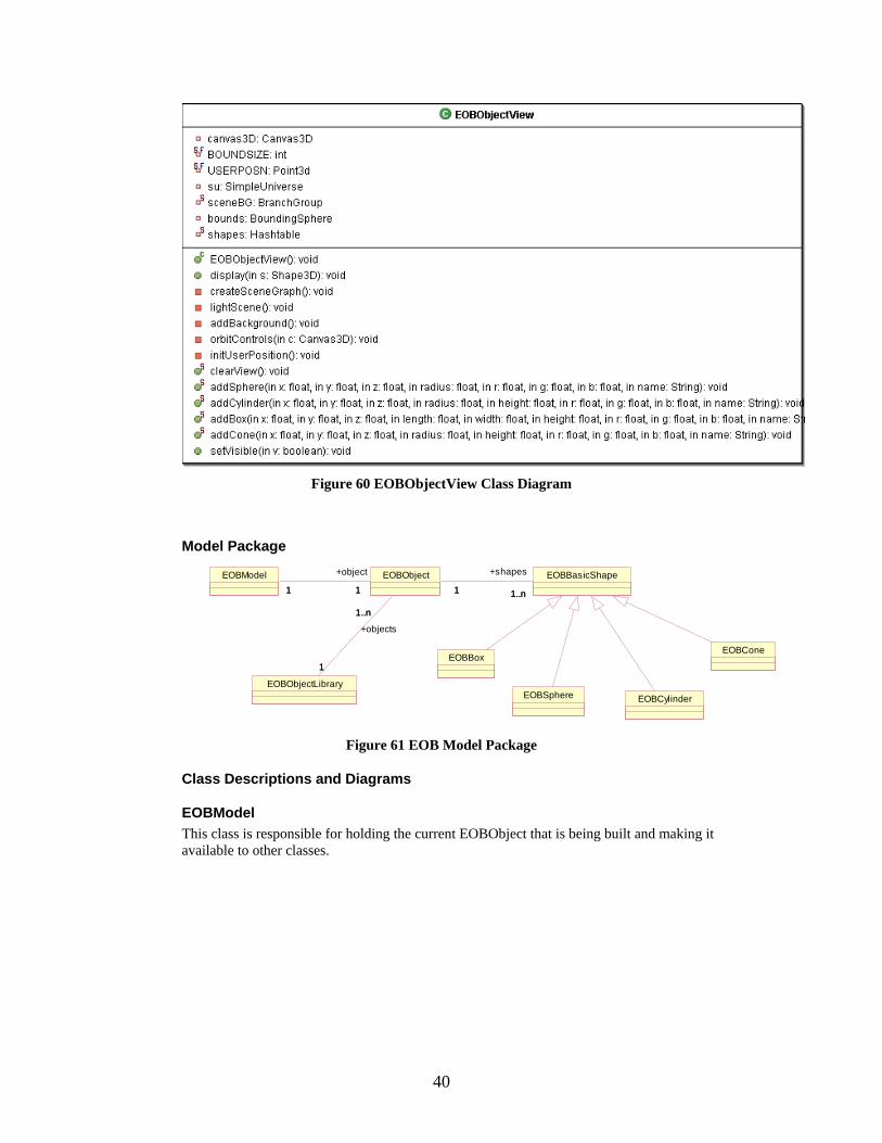
Figure 60 EOBObjectView Class Diagram
Model Package
EOBBoxEOBCone
EOBCylinderEOBSphere
EOBBasicShapeEOBModel
EOBObjectLibrary
EOBObject1 1..n1
+shapes
1..n1 11
+object
1
1
1..n
1
+objects
1..n
Figure 61 EOB Model Package
Class Descriptions and Diagrams
EOBModel This class is responsible for holding the current EOBObject that is being built and making it available to other classes.
40

Figure 62 EOBModel Class Diagram
EOBObject This class is a collection of EOBBasicShapes that are to be used in the environment. It is also responsible for building its XML definition
Figure 63 EOBObject Class Diagram
EOBBasicShape This class is the super class for the primitive shapes; EOBBox, EOBCone, EOBSphere, and EOBCylinder. It is responsible for building the XML definition for the primitive shapes.
41
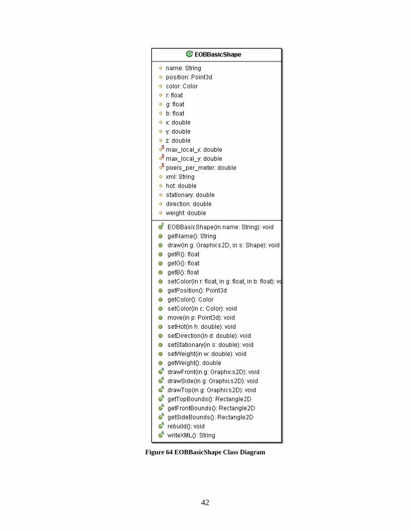
Figure 64 EOBBasicShape Class Diagram
42

EOBBox This class represents a box shape. It holds all the information necessary to represent a three dimensional box shape.
Figure 65 EOBBox Class Diagram
EOBCone This class represents a cone shape. It holds all the information necessary to represent a three dimensional cone.
43

Figure 66 EOBCone Class Diagram
EOBSphere This class represents a sphere shape. It holds all the information necessary to represent a three dimensional sphere.
44
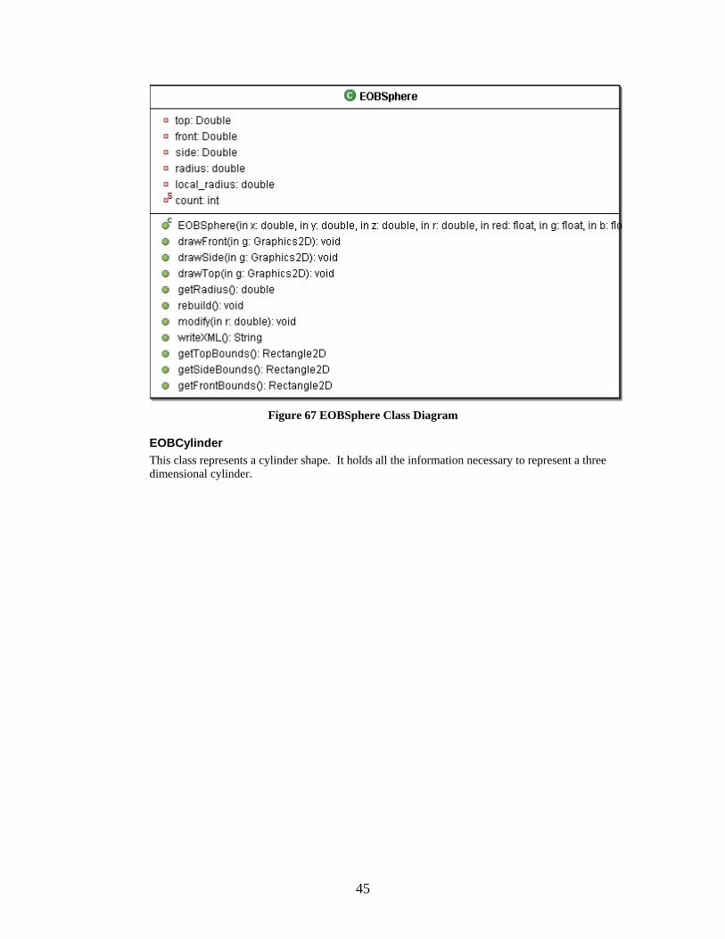
Figure 67 EOBSphere Class Diagram
EOBCylinder This class represents a cylinder shape. It holds all the information necessary to represent a three dimensional cylinder.
45

Figure 68 EOBCylinder Class Diagram
EOBObjectLibrary This class will hold all the EOBObjects that are saved to disk.
Figure 69 EOBObjectLibrary Class Diagram
Sequence Diagrams The following sequence diagrams show some of the main functions that the Environment Object Builder will perform.
46

Modifying and Moving a Box Shape The following sequence diagram show selecting a box and moving it. It also shows selecting a box and modifying its dimensions.
: User : EOBFrontMouseHandler : EOBModel
: EOBBoxPropertiesWindow
: EOBBox
click on surface
getData
change x coordinate
move
Figure 70 Sequence Diagram for Moving a Box
Environment Terrain Builder The Environment Terrain Builder is a graphical tool for building surfaces to be used by the Environment Model Builder. The tool will provide a building surface to allow the user to specify the elevation of a given region on the surface. The user will also be able to define physical properties of the surface. A three dimensional view will be provided to observe how the terrain will look in 3D. Finally a XML view will be provided to give a textual description of the terrain. The following sections will describe the packages of the Environment Terrain Builder.
47

Package View
ETB Application
ETB Controller ETB Model
ETB View
Figure 71 ETB Package View
Application Package
ETBApplication
Figure 72 ETB Application Package
Class Descriptions and Diagrams
ETBApplication This class is just intended to have the main method for this program and create the ETBController and set it visible.
Figure 73 ETBApplication Class Diagram
Controller Package
ETBController
Figure 74 ETB Controller Package
48

Class Descriptions and Diagrams
ETBController This class is the main frame of the application. It will handle all the menu item actions. It is responsible for loading files, saving files to disk, and saving ETBTerrains to the library.
Figure 75 ETBController Class Diagram
49

View Package
ETBThreeDimensionalView
ETBXMLView
ETBTerrainFinder
ETBTerrainView
ETBView
1 +threeD1 1
+xml
1
ETBTerrainPreview
1+finder 11
+view1
ETBDrawingView1+canvas 1
1+preview
1ETBBuildingSurface
1+builder
1
Figure 76 ETB View Package
Class Descriptions and Diagrams
ETBView This class is a container for the ETBThreeDimensionalView, ETBDrawingView, and ETBXMLView.
Figure 77 ETBView Class Diagram
ETBThreeDimensionalView This class will show the three dimensional view of the current ETBTerrain. From this view the user will be able to view the ETBTerrain from any angle.
50

Figure 78 ETBThreeDimensionalView Class Diagram
ETBXMLView This class is responsible for displaying the XML definition of the current ETBTerrain. The XML will represent the contents that will be saved to disk.
Figure 79 ETBXMLView Class Diagram
ETBDrawingView This class is a container for the ETBBuildingSurface and ETBTerrainPreview.
Figure 80 ETBDrawingView Class Diagram
51

ETBBuildingSurface This class is responsible for providing a surface to create an ETBTerrain. It will provide the user an interface to specify the elevation of sections of the ETBTerrain.
Figure 81 ETBBuildingSurface Class Diagram
ETBTerrainPreview This class is a container for the ETBTerrainView and ETBTerrainFinder. It will provide the ability to add the currently selected ETBTerrain to the ETBBuildingSurface.
Figure 82 ETBTerrainPreview Class Diagram
ETBTerrainFinder This class is responsible for providing a list of all available ETBTerrains in the ETBTerrainLibrary for the user to select.
52

Figure 83 ETBTerrainFinder Class Diagram
ETBTerrainView This class is responsible for providing a thumb-nail view of the currently selected ETBTerrain.
Figure 84 ETBTerrainView Class Diagram
Model Package
ETBModel
ETBTerrainLibrary
ETBTerrain1 11
+terrain
1
1
1..n
1
+terrains 1..n
Figure 85 ETB Model Package
53

Class Descriptions and Diagrams
ETBModel This class is responsible for holding the current ETBTerrain that is being built and making it available to other classes.
Figure 86 ETBModel Class Diagram
ETBTerrain This class represents a terrain for the environment. It will consist of an elevation map and a collection of coordinates. The elevation map will specify the height of all the desired locations. The terrain will be represented by strips of triangles.
54

Figure 87 ETBTerrain Class Diagram
ETBTerrainLibrary This class will hold all the EOBTerrains that are saved to disk.
Figure 88 ETBTerrainLibrary Class Diagram
Sequence Diagrams The following sequence diagram shows the main function of the Environment Terrain Builder.
55
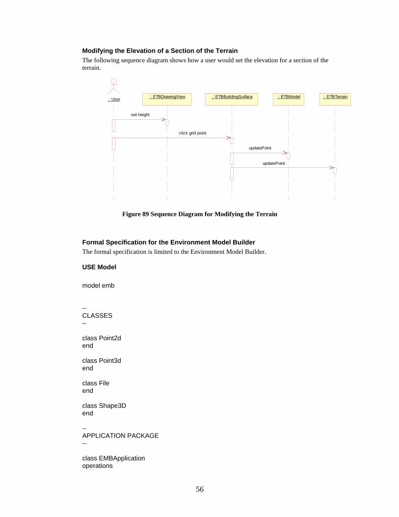
Modifying the Elevation of a Section of the Terrain The following sequence diagram shows how a user would set the elevation for a section of the terrain.
: User : ETBBuildingSurface : ETBModel : ETBTerrain : ETBDrawingView
updatePoint
updatePoint
set height
click grid point
Figure 89 Sequence Diagram for Modifying the Terrain
Formal Specification for the Environment Model Builder The formal specification is limited to the Environment Model Builder.
USE Model model emb -- CLASSES -- class Point2d end class Point3d end class File end class Shape3D end -- APPLICATION PACKAGE -- class EMBApplication operations
56
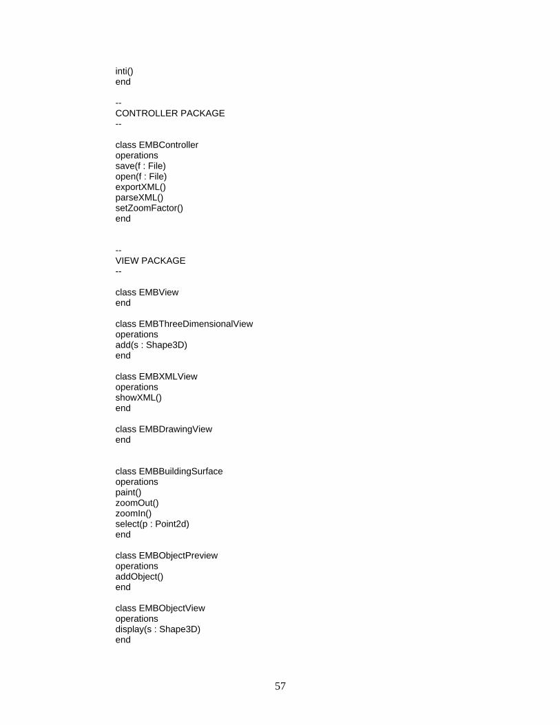
inti() end -- CONTROLLER PACKAGE -- class EMBController operations save(f : File) open(f : File) exportXML() parseXML() setZoomFactor() end -- VIEW PACKAGE -- class EMBView end class EMBThreeDimensionalView operations add(s : Shape3D) end class EMBXMLView operations showXML() end class EMBDrawingView end class EMBBuildingSurface operations paint() zoomOut() zoomIn() select(p : Point2d) end class EMBObjectPreview operations addObject() end class EMBObjectView operations display(s : Shape3D) end
57

class EMBObjectFinder operations searchDB() getCurrent() : EMBObject select() end class EMBTerrainPreview operations addTerrain() end class EMBTerrainView operations display(s : Shape3D) end class EMBTerrainFinder operations searchDB() getCurrent() : EMBTerrain select() end -- MODEL PACKAGE -- class EMBEnvironmentLibrary operations getData() : Set(EMBEnvironment) addData(e : EMBEnvironment) end class EMBObjectLibrary operations getData() : Set(EMBObject) addData(o : EMBObject) end class EMBTerrainLibrary operations getData() : Set(EMBTerrain) addData(t : EMBTerrain) end class EMBModel operations getData() : EMBEnvironment addObject(o : EMBObject) addTerrain(t : EMBTerrain) deleteObject(o : EMBObject) deleteTerrain(t : EMBTerrain) end
58

class EMBEnvironment attributes name : String operations writeXML() : String addObject(o : EMBObject) addTerrain(t : EMBTerrain) deleteObject(o : EMBObject) deleteTerrain(t : EMBTerrain) end class EMBTerrain attributes name : String operations getHeight(x : Real, z : Real) : Real writeXML() : String end class EMBObject attributes name : String x : Real y : Real z : Real length : Real width : Real height : Real operations writeXML() : String addShape(s : EMBBasicShape) move(p : Point3d) end class EMBBasicShape attributes name : String x : Real y : Real z : Real operations writeXML() : String end class EMBBox < EMBBasicShape attributes length : Real width : Real height : Real end class EMBCylinder < EMBBasicShape attributes height : Real radius : Real end
59

class EMBCone < EMBBasicShape attributes height : Real radius : Real end class EMBSphere < EMBBasicShape attributes radius : Real end -- ASSOCIATIONS -- -- VIEW PACKAGE -- association ThreeD between EMBView[1] EMBThreeDimensionalView[1] role threeD end association Canvas between EMBView[1] EMBDrawingView[1] role canvas end association XML between EMBView[1] EMBXMLView[1] role xml end association TerrPreview between EMBDrawingView[1] EMBTerrainPreview[1] role terrainPrev end association Builder between EMBDrawingView[1] EMBBuildingSurface[1] role builder end association ObjPreview between EMBDrawingView[1] EMBObjectPreview[1] role objectPrev end association TerrainList between EMBTerrainPreview[1] EMBTerrainFinder[1] role finder end
60

association TerrainThumbNail between EMBTerrainPreview[1] EMBTerrainView[1] role view end association ObjectList between EMBObjectPreview[1] EMBObjectFinder[1] role finder end association ObjectThumbNail between EMBObjectPreview[1] EMBObjectView[1] role view end -- MODEL PACKAGE -- association Model between EMBModel[1] EMBEnvironment[1] role environment end association EnvDatabase between EMBEnvironment[1..*] role environments EMBEnvironmentLibrary[1] end association Surface between EMBEnvironment[1] EMBTerrain[1] role terrain end association Objects between EMBEnvironment[1] EMBObject[1..*] role objects ordered end association TerrainDatabase between EMBTerrain[1..*] role terrains EMBTerrainLibrary[1] end association ObjectDatabase between EMBObject[1..*] role objects EMBObjectLibrary[1] end association Shapes between EMBObject[1] EMBBasicShape[1..*] role shapes end --
61

CONSTRAINTS -- constraints -- Relations -- -- Unique names of environments in Environment Library -- context e : EMBEnvironmentLibrary inv UniqueNameEnvironmentLibrary: e.environments->forAll(p1,p2 | p1 <> p2 implies p1.name <> p2.name) -- --Unique names of objects in Object Library -- context o : EMBObjectLibrary inv UniqueNameObjectLibrary: o.objects->forAll(p1,p2 | p1 <> p2 implies p1.name <> p2.name) -- --Unique names of terrains in Terrain Library -- context t : EMBTerrainLibrary inv UniqueNameTerrainLibrary: t.terrains->forAll(p1,p2 | p1 <> p2 implies p1.name <> p2.name) -- --Unique names for all shapes of an object -- context obj : EMBObject inv UniqueNameObjectShapes: obj.shapes->forAll(p1,p2 | p1 <> p2 implies p1.name <> p2.name) -- --Every box has positive length, width and height -- context b : EMBBox inv BoxPositiveLength: b.length > 0 inv BoxPositiveWidth: b.width > 0 inv BOXPositiveHeight: b.height > 0 -- --Every sphere has positive radius -- context s : EMBSphere inv SpherePositiveRadius:
62

s.radius > 0 -- --Every cylinder has positive height and radius -- context cyl : EMBCylinder inv CylinderPositiveHeight: cyl.height > 0 inv CylinderPositiveRadius: cyl.radius > 0 -- --Every cone has positive height and radius -- context c : EMBCone inv ConePositiveHeight: c.height > 0 inv ConePositiveRadius: c.radius > 0 -- Operations -- --Deleting an object must remove it while the other object are unchanged context EMBEnvironment::deleteObject(o : EMBObject) pre Current: objects->includes(o) post Deleted: objects = objects@pre->excluding(o) --Added objects must be unique context EMBEnvironment::addObject(o : EMBObject) pre Current: objects->excludes(o) post Added: objects = objects@pre->including(o) --Additional OCL statements at request of Committee --Elevation adjustment Context EMBEnvironment::elevationAdj(o:EMBObject) Post adjusted: o.y = terrain->getHeight(o.x,o.z) --Shapes with in Object bounds context o : EMBObject inv bounds: shapes->forall( s | (o.x – o.length/2 < s.x < o.x + o.length/2) and (o.y – o.height/2 < s.y < o.y + o.height/2) and (o.z – o.width/2 < s.z < o.z + o.width/2)) --Move to back context EMBEnvironment::moveToBack(o:EMBObject) post back : objects->last = o post size : objects@pre->asSet() = object->asSet()
63

Chapter 4. Inspection Checklist
Introduction The purpose of this document is to provide a checklist for the technical inspectors of the Environment Model Building Tool. The checklist will be used to document the items which are to be inspected. The goal of the technical inspection is to aid the developer in checking for correctness and consistency with the architectural design and formal specification documents.
Items to be Inspected UML Diagrams Class diagrams Sequence diagrams Class descriptions Formal Specification USE model (sections 2.2-2.5 of the Architecture Design were formally specified)
Formal Technical Inspectors Cem Oguzhan Kevin Sung
Formal Technical Inspection Checklist
Table 2 Technical Inspection Checklist
Inspection Item Pass/Fail/Partial Comments
1. The symbols used in the class diagrams conform to the UML standards
2. The symbols used in the sequence diagrams conform to the UML standards
3. The class diagrams have a corresponding description provide in the architectural design document
4. The descriptions of all class diagrams are clear and makes sense
5. The messages passed between objects in the sequence diagrams can be found in the corresponding class diagram as public methods
6. All classes in the Environment
64

Model Builder (sections 2.2-2.5 of Architecture Design) are found in the USE model (section 5 of the Architecture Design)
7. The role names and multiplicities in the USE model match with the role names and multiplicities of the UML diagrams for the Environment Model Builder (sections 2.2-2.5 of Architecture Design )
8. The attributes in the USE model match with the attributes of the corresponding class diagrams (sections 2.2-2.5 of the Architecture Design)
9. The operations in the USE model match with the corresponding methods in the class diagrams (sections 2.2-2.5 of the Architecture Design)
Chapter 5. Component Design
Introduction This document will provide brief descriptions and class diagrams of the applications and classes for the EMBT. A detail description of the methods and attributes is provided in the Javadoc documentation.
Environment Model Builder The Environment Model Builder is a graphical tool to create an environment from a terrain and objects. The tool will have a building surface to place the terrain and objects. The user will be able to move the objects to the desired location. There will also be a three dimensional view to observer what the terrain and objects look like in 3D. The following sections will describe the different packages of the Environment Model Builder in detail.
Package View
65

EMB Application
EMB Controller
EMB View
EMB Model
Figure 90 EMB Package View
Application Package
Class Descriptions and Diagrams
EMBApplication This class is just intended to have the main method for this program and create the EMBController and set it visible.
Figure 91 EMBApplication Class Diagram
Controller Package
Class Descriptions and Diagrams
EMBController This class is the main frame of the application. It will handle all the menu item actions. It is responsible for loading files, saving files to disk, and saving EMBEnvironments to the library.
66

Figure 92 EMBController Class Diagram
EMBBuildingSurfaceMouseHandler This class is responsible for handling mouse events for the building surface. In particular it will wait for mouse clicks and determine if one of the objects was clicked on. If an object is clicked on it will provide a properties window for that object.
Figure 93 EMBBuildingSurfaceMouseHandler
EMBObjectPropertiesWindow This class provides the properties window for an object. It will provide controls to move the object to a new location.
67

Figure 94 EMBObjectPropertiesWindow Class Diagram
View Package
Class Descriptions and Diagrams
EMBView This class is a container for the EMBThreeDimensionalView, EMBDrawingView, and EMBXMLView.
Figure 95 EMBView Class Diagram
EMBThreeDimensionalView This class will show the three dimensional view of the current EMBEnvironment. From this view the user will be able to view the EMBEnvironment from any angle.
68
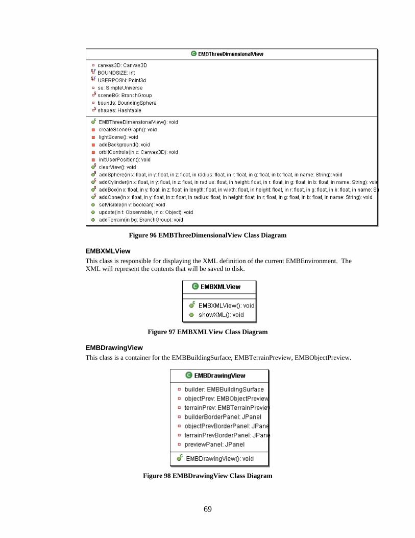
Figure 96 EMBThreeDimensionalView Class Diagram
EMBXMLView This class is responsible for displaying the XML definition of the current EMBEnvironment. The XML will represent the contents that will be saved to disk.
Figure 97 EMBXMLView Class Diagram
EMBDrawingView This class is a container for the EMBBuildingSurface, EMBTerrainPreview, EMBObjectPreview.
Figure 98 EMBDrawingView Class Diagram
69

EMBTerrainPreview This class is a container for the EMBTerrainFinder and EMBTerrainView. It will also add the currently selected EMBTerrain to the EMBModel.
Figure 99 EMBTerrainPreview Class Diagram
EMBTerrainFinder This class is responsible for providing a list of all available EMBTerrains in the EMBTerrainLibrary for the user to select.
Figure 100 EMBTerrainFinder Class Diagram
EMBTerrainView This class is responsible for providing a thumb-nail view of the currently selected EMBTerrain.
70

Figure 101 EMBTerrainView Class Diagram
EMBObjectPreview This class is a container for the EMBObjectFinder and EMBObjectView. It will also add the currently selected EMBObject to the EMBBuildingSurface and EMBModel.
Figure 102 EMBObjectPreview Class Diagram
EMBObjectFinder This class is responsible for providing a list of all available EMBObjects in the EMBObjectLibrary for the user to select.
71

Figure 103 EMBObjectFinder Class Diagram
EMBObjectView This class is responsible for providing a thumb-nail view of the currently selected EMBObject.
Figure 104 EMBObjectView Class Diagram
EMBBuildingSurface This class is responsible for displaying the top 2-D view of the current EMBEnvironment. From this view the user will be able arrange the objects and terrains that have been added to it. This view will also allow for removal of terrains and objects.
Figure 105 EMBBuildingSurface Class Diagram
72
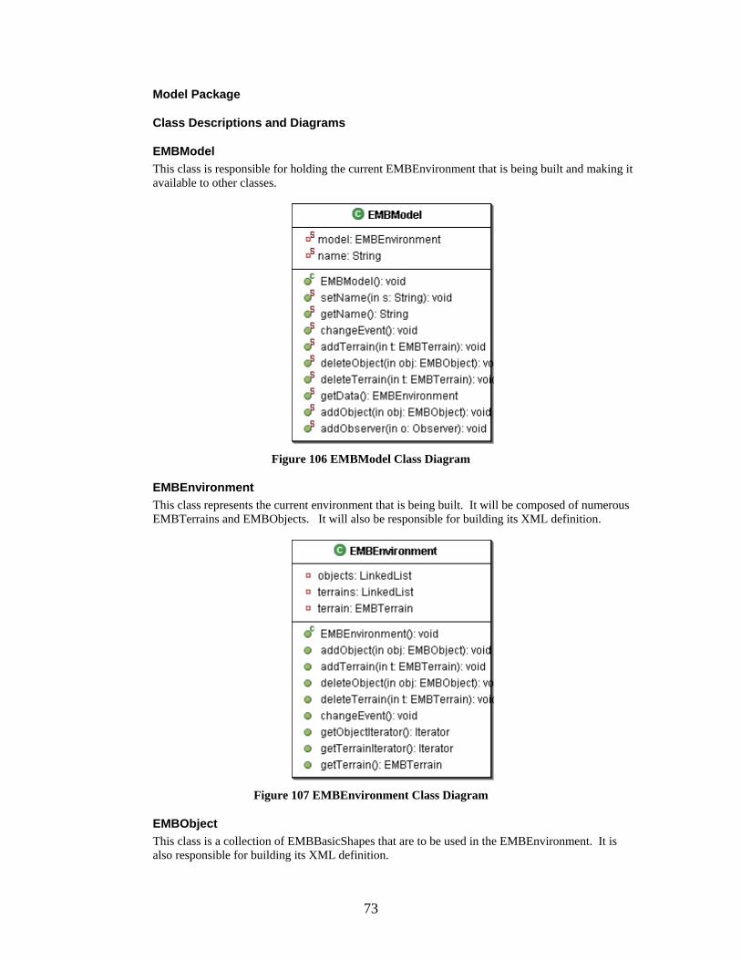
Model Package
Class Descriptions and Diagrams
EMBModel This class is responsible for holding the current EMBEnvironment that is being built and making it available to other classes.
Figure 106 EMBModel Class Diagram
EMBEnvironment This class represents the current environment that is being built. It will be composed of numerous EMBTerrains and EMBObjects. It will also be responsible for building its XML definition.
Figure 107 EMBEnvironment Class Diagram
EMBObject This class is a collection of EMBBasicShapes that are to be used in the EMBEnvironment. It is also responsible for building its XML definition.
73

Figure 108 EMBObject Class Diagram
EMBBasicShape This class is the super class for the primitive shapes; EMBBox, EMBCone, EMBSphere, and EMBCylinder. It is responsible for building the XML definition for the primitive shapes.
74

Figure 109 EMBBasicShape Class Diagram
EMBBox This class represents a box shape. It holds all the information necessary to represent a three dimensional box shape.
Figure 110 EMBBox Class Diagram
75

EMBCone This class represents a cone shape. It holds all the information necessary to represent a three dimensional cone.
Figure 111 EMBCone Class Diagram
EMBSphere This class represents a sphere shape. It holds all the information necessary to represent a three dimensional sphere.
Figure 112 EMBSphere Class Diagram
EMBCylinder This class represents a cylinder shape. It holds all the information necessary to represent a three dimensional cylinder.
Figure 113 EMBCylinder Class Diagram
EMBTerrain This class represents a terrain for the environment. It will consist of an elevation map and a collection of coordinates. The elevation map will specify the height of all the desired locations. The terrain will be represented by strips of triangles.
76

Figure 114 EMBTerrain Class Diagram
EMBObjectLibrary This class will hold all the EMBObjects that are saved to the object library.
Figure 115 EMBObjectLibrary Class Diagram
EMBTerrainLibrary This class will hold all the EMBTerrains that are saved to the object library.
77

Figure 116 EMBTerrainLibrary Class Diagram
Environment Object Builder The Environment Object Builder is a graphical tool for building complex shapes/object from primitive shapes. The tool will have three drawing surfaces representing a two dimensional view from the top, side, and front. The user will be able to move and resize the primitive shape from any of the three drawing surfaces. There will also be a three dimensional view provided to observe the created object in 3D. Finally there will be a XML view to show the textual description of object. The following sections will describe the packages of the Environment Object Builder
Package View
EOB Application
EOB Controller
EOB View
EOB Model
Figure 117 EOB Package View
Application Package
Class Descriptions and Diagrams
EOBApplication This class is just intended to have the main method for this program and create the EOBController and set it visible.
78

Figure 118 EOBApplication Class Diagram
Controller Package
Class Descriptions and Diagrams
EOBController This class is the main frame of the application. It will handle all the menu item actions. It is responsible for loading files, saving files to disk, and saving EOBObjects to the library.
Figure 119 EOBController Class Diagram
EOBBoxPropertiesWindow This class provides a JDialog window with controls for modifying a EOBBox.
79

Figure 120 EOBBoxPropertiesWindow Class Diagram
EOBConePropertiesWindow This class provides a JDialog window with controls for modifying a EOBCone.
80

Figure 121 EOBConePropertiesWindow Class Diagram
EOBCylinderPropertiesWindow This class provides a JDialog window with controls for modifying a EOBCylinder.
81

Figure 122 EOBCylinderPropertiesWindow Class Diagram
EOBFrontMouseHandler This class is responsible for handling mouse events for the front building surface. In particular it will wait for mouse clicks and determine if one of the objects was clicked on. If an object is clicked on it will provide a properties window for that object.
Figure 123 EOBFrontMouseHandler Class Diagram
EOBSideMouseHandler This class is responsible for handling mouse events for the side building surface. In particular it will wait for mouse clicks and determine if one of the objects was clicked on. If an object is clicked on it will provide a properties window for that object.
82

Figure 124 EOBSideMouseHandler Class Diagram
EOBSpherePropertiesWindow This class provides a JDialog window with controls for modifying a EOBSphere.
Figure 125 EOBSpherePropertiesWindow Class Diagram
EOBTopMouseHandler This class is responsible for handling mouse events for the top building surface. In particular it will wait for mouse clicks and determine if one of the objects was clicked on. If an object is clicked on it will provide a properties window for that object.
Figure 126 EOBTopMouseHandler Class Diagram
83

View Package
Class Descriptions and Diagrams
EOBView This class is a container for the EOBThreeDimensionalView, EOBDrawingView, and EOBXMLView.
Figure 127 EOBView Class Diagram
EOBThreeDimensionalView This class will show the three dimensional view of the current EOBObject. From this view the user will be able to view the EOBObject from any angle.
Figure 128 EOBThreeDimensionalView Class Diagram
EOBDrawingView This class is the container for the EOBTopDrawingView, EOBSideDrawingView, EOBFrontDrawingView, and EOBObjectPreview.
84

Figure 129 EOBDrawingView Class Diagram
EOBXMLView This class is responsible for displaying the XML definition of the current EOBObject. The XML will represent the contents that will be saved to disk.
Figure 130 EOBXMLView Class Diagram
EOBSideDrawingView This class is responsible for providing a drawing surface for EOBBasicShapes. This view will represent the side view. The user will be able to move and change the properties of the EOBBasicShapes from this view.
Figure 131 EOBSideDrawingView Class Diagram
EOBFrontDrawingView This class is responsible for providing a drawing surface for EOBBasicShapes. This view will represent the front view. The user will be able to move and change the properties of the EOBBasicShapes from this view.
85

Figure 132 EOBFrontDrawingView Class Diagram
EOBTopDrawingView This class is responsible for providing a drawing surface for EOBBasicShapes. This view will represent the top view. The user will be able to move and change the properties of the EOBBasicShapes from this view.
Figure 133 EOBTopDrawingView Class Diagram
EOBObjectPreview This class is the container for the EOBObjectFinder and EOBObjectView. It will also add the currently selected EOBBasicShapes to the EOBSideDrawingView, EOBFrontDrawingView, and EOBTopDrawingView.
Figure 134 EOBObjectPreview Class Diagram
86

EOBObjectFinder This class is responsible for providing a list of all available EOBObjects in the EOBObjectLibrary for the user to select.
Figure 135 EOBObjectFinder Class Diagram
EOBObjectView This class is responsible for providing a thumb-nail view of the currently selected EOBObject.
Figure 136 EOBObjectView Class Diagram
Model Package
Class Descriptions and Diagrams
EOBModel This class is responsible for holding the current EOBObject that is being built and making it available to other classes.
87

Figure 137 EOBModel Class Diagram
EOBObject This class is a collection of EOBBasicShapes that are to be used in the environment. It is also responsible for building its XML definition
Figure 138 EOBObject Class Diagram
EOBBasicShape This class is the super class for the primitive shapes; EOBBox, EOBCone, EOBSphere, and EOBCylinder. It is responsible for building the XML definition for the primitive shapes.
88

Figure 139 EOBBasicShape Class Diagram
89

EOBBox This class represents a box shape. It holds all the information necessary to represent a three dimensional box shape.
Figure 140 EOBBox Class Diagram
EOBCone This class represents a cone shape. It holds all the information necessary to represent a three dimensional cone.
90

Figure 141 EOBCone Class Diagram
EOBSphere This class represents a sphere shape. It holds all the information necessary to represent a three dimensional sphere.
91

Figure 142 EOBSphere Class Diagram
EOBCylinder This class represents a cylinder shape. It holds all the information necessary to represent a three dimensional cylinder.
92
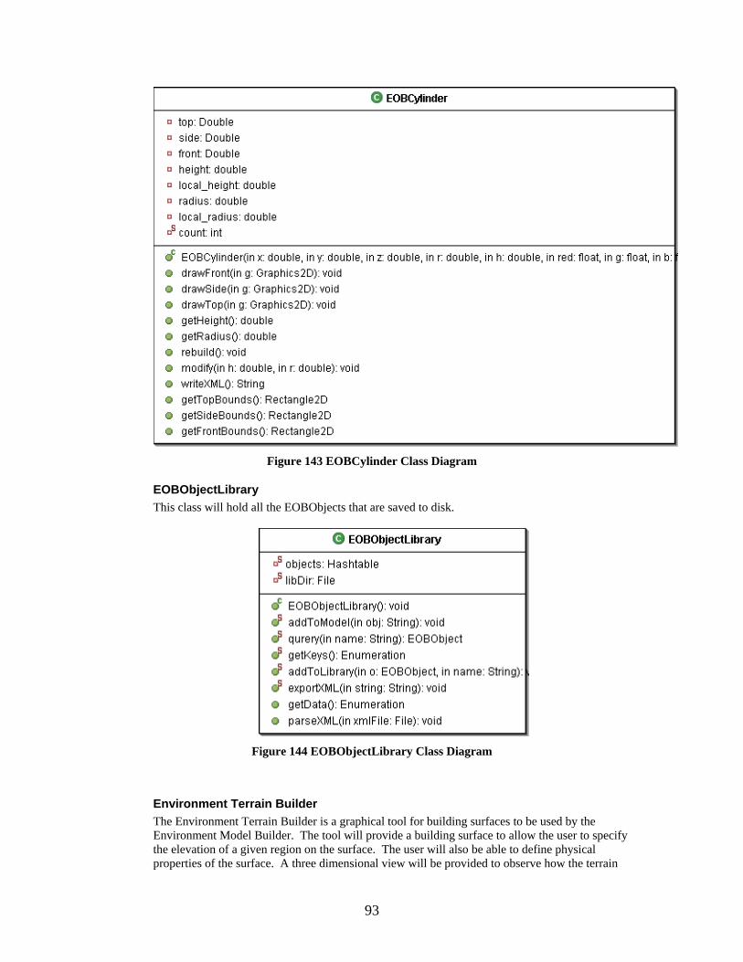
Figure 143 EOBCylinder Class Diagram
EOBObjectLibrary This class will hold all the EOBObjects that are saved to disk.
Figure 144 EOBObjectLibrary Class Diagram
Environment Terrain Builder The Environment Terrain Builder is a graphical tool for building surfaces to be used by the Environment Model Builder. The tool will provide a building surface to allow the user to specify the elevation of a given region on the surface. The user will also be able to define physical properties of the surface. A three dimensional view will be provided to observe how the terrain
93
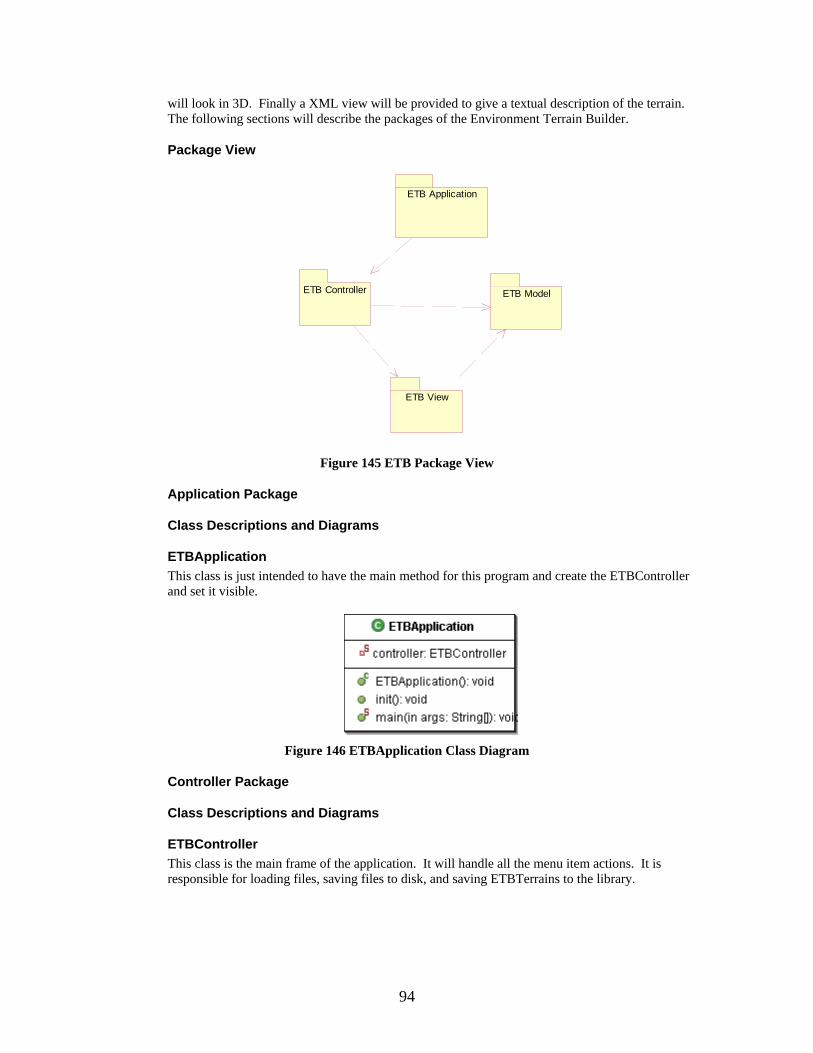
will look in 3D. Finally a XML view will be provided to give a textual description of the terrain. The following sections will describe the packages of the Environment Terrain Builder.
Package View
ETB Application
ETB Controller ETB Model
ETB View
Figure 145 ETB Package View
Application Package
Class Descriptions and Diagrams
ETBApplication This class is just intended to have the main method for this program and create the ETBController and set it visible.
Figure 146 ETBApplication Class Diagram
Controller Package
Class Descriptions and Diagrams
ETBController This class is the main frame of the application. It will handle all the menu item actions. It is responsible for loading files, saving files to disk, and saving ETBTerrains to the library.
94

Figure 147 ETBController Class Diagram
View Package
Class Descriptions and Diagrams
ETBView This class is a container for the ETBThreeDimensionalView, ETBDrawingView, and ETBXMLView.
Figure 148 ETBView Class Diagram
95

ETBThreeDimensionalView This class will show the three dimensional view of the current ETBTerrain. From this view the user will be able to view the ETBTerrain from any angle.
Figure 149 ETBThreeDimensionalView
ETBXMLView This class is responsible for displaying the XML definition of the current ETBTerrain. The XML will represent the contents that will be saved to disk.
Figure 150 ETBXMLView Class Diagram
ETBDrawingView This class is a container for the ETBBuildingSurface and ETBTerrainPreview.
96

Figure 151 ETBDrawingView Class Diagram
ETBBuildingSurface This class is responsible for providing a surface to create an ETBTerrain. It will provide the user an interface to specify the elevation of sections of the ETBTerrain.
Figure 152 ETBBuildingSurface Class Diagram
ETBTerrainPreview This class is a container for the ETBTerrainView and ETBTerrainFinder. It will provide the ability to add the currently selected ETBTerrain to the ETBBuildingSurface.
97

Figure 153 ETBTerrainPreview Class Diagram
ETBTerrainFinder This class is responsible for providing a list of all available ETBTerrains in the ETBTerrainLibrary for the user to select.
Figure 154 ETBTerrainFinder
ETBTerrainView This class is responsible for providing a thumb-nail view of the currently selected ETBTerrain.
98
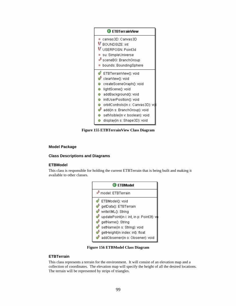
Figure 155 ETBTerrainView Class Diagram
Model Package
Class Descriptions and Diagrams
ETBModel This class is responsible for holding the current ETBTerrain that is being built and making it available to other classes.
Figure 156 ETBModel Class Diagram
ETBTerrain This class represents a terrain for the environment. It will consist of an elevation map and a collection of coordinates. The elevation map will specify the height of all the desired locations. The terrain will be represented by strips of triangles.
99

Figure 157 ETBTerrain Class Diagram
ETBTerrainLibrary This class will hold all the EOBTerrains that are saved to disk.
Figure 158 ETBTerrainLibrary Class Diagram
100

Chapter 6. XML Definition
Introduction This document will describe the XML definitions for the file formats of each of the tools for the EMBT.
XML Definition for Object Builder <?xml version="1.0"?> <!DOCTYPE object [ <!ELEMENT object (name,x,y,z,shape*)> <!ELEMENT shape (*primative)> <!ELEMENT primative (sphere|box|cone|cylinder)> <!ELEMENT sphere (name,x,y,z,direction,radius,color,hot,stationary,weight)> <!ELEMENT box (name,x,y,z,direction,color,length,width,height,hot,stationary,weight)> <!ELEMENT cone (name,x,y,z,direction,radius,height,color,hot,stationary,weight)> <!ELEMENT cylinder (name,x,y,z,direction,radius,height,color,hot,stationary,weight)> <!ELEMENT x (#PCDATA)> <!ELEMENT y (#PCDATA)> <!ELEMENT z (#PCDATA)> <!ELEMENT radius (#PCDATA)> <!ELEMENT color (#PCDATA)> <!ELEMENT length (#PCDATA)> <!ELEMENT width (#PCDATA)> <!ELEMENT height (#PCDATA)> <!ELEMENT name (#PCDATA)> <!ELEMENT direction (#PCDATA)> <!ELEMENT hot (#PCDATA)> <!ELEMENT stationary (#PCDATA)> <!ELEMENT weight (#PCDATA)> ]>
PCDATA Descriptions x – an integer that represents the x-axis coordinate (note for the object the x coordinate is absolute while the primitive x coordinate is relative to the object) y – an integer that represents the y-axis coordinate (note for the object the y coordinate is absolute while the primitive y coordinate is relative to the object) z – an integer that represents the z-axis coordinate (note for the object the z coordinate is absolute while the primitive z coordinate is relative to the object) radius – a double that represents the radius of the shape measured in meters color – a string the represents the color of the shape, it will be in the form of “r g b” (e.g. “0.0 1.0. 0.0”. length – a double that represents the length of the shape measured in meters width – a double that represents the width of the shape measured in meters height – a double that represents the height of the shape measured in meters name – a string that represents the id of the shape or object
101

direction – a double that represents the number of radians that the shape is rotated around the y-axis hot – a double that represents the temperature of the shape stationary – a double that indicates if the object can move or not (0.0 not stationary 1.0 stationary) weight – a double that indicates the weight of the shape
XML Definition for Terrain Builder <?xml version="1.0"?> <!DOCTYPE terrain [ <!ELEMENT terrain (name,num-points,points-per-row,size,*point)> <!ELEMENT name (#PCDATA)> <!ELEMENT num-points (#PCDATA)> <!ELEMENT points-per-row (#PCDATA)> <!ELEMENT size (x-min,x-max,y-min,y-max)> <!ELEMENT x-min (#PCDATA)> <!ELEMENT x-max (#PCDATA)> <!ELEMENT y-min (#PCDATA)> <!ELEMENT y-max (#PCDATA)> <!ELEMENT point (index,x,y,z)> <!ELEMENT index (#PCDATA)> <!ELEMENT x (#PCDATA)> <!ELEMENT y (#PCDATA)> <!ELEMENT z (#PCDATA)> ]>
PCDATA Descriptions name – a string that represents the id of the terrain num-points – a integer that represents to total number of points that make up the point of triangles of the terrain points-per-row – a integer that represents how many points per row of triagles x-min – the minimum x-axis value for the terrain measured in meters x-max – the maximum x-axis value for the terrain measured in meters y-min – the minimum y-axis value for the terrain measured in meters y-max – the maximum y-axis value for the terrain measured in meters x – an integer that represents the x-axis coordinate of the point y – an integer that represents the y-axis coordinate of the point z – an integer that represents the z-axis coordinate of the point index – an integer that represents the id of a point
102

XML Definition for Environment Builder <?xml version="1.0"?> <!DOCTYPE env-model [ <!ELEMENT env-model (terrain*,object*)> <!ELEMENT terrain (name,num-points,points-per-row,size,*point)> <!ELEMENT name (#PCDATA)> <!ELEMENT num-points (#PCDATA)> <!ELEMENT points-per-row (#PCDATA)> <!ELEMENT size (x-min,x-max,y-min,y-max)> <!ELEMENT x-min (#PCDATA)> <!ELEMENT x-max (#PCDATA)> <!ELEMENT y-min (#PCDATA)> <!ELEMENT y-max (#PCDATA)> <!ELEMENT point (index,x,y,z)> <!ELEMENT index (#PCDATA)> <!ELEMENT x (#PCDATA)> <!ELEMENT y (#PCDATA)> <!ELEMENT z (#PCDATA)> <!ELEMENT object (name,shape*)> <!ELEMENT shape (*primative)> <!ELEMENT primative (sphere|box|cone|cylinder)> <!ELEMENT sphere (name,x,y,z,direction,radius,color,hot,stationary,weight)> <!ELEMENT box (name,x,y,z,direction,color,length,width,height,hot,stationary,weight)> <!ELEMENT cone (name,x,y,z,direction,radius,height,color,hot,stationary,weight)> <!ELEMENT cylinder (name,x,y,z,direction,radius,height,color,hot,stationary,weight)> <!ELEMENT x (#PCDATA)> <!ELEMENT y (#PCDATA)> <!ELEMENT z (#PCDATA)> <!ELEMENT radius (#PCDATA)> <!ELEMENT color (#PCDATA)> <!ELEMENT length (#PCDATA)> <!ELEMENT width (#PCDATA)> <!ELEMENT height (#PCDATA)> <!ELEMENT name (#PCDATA)> <!ELEMENT direction (#PCDATA)> <!ELEMENT hot (#PCDATA)> <!ELEMENT stationary (#PCDATA)> <!ELEMENT weight (#PCDATA)> ]>
PCDATA Descriptions See sections 2.1 and 3.1 above.
Chapter 7. Software Quality Assurance
Purpose This document is intended to define the steps that will be taken to ensure the Environment Model Building Tool will achieve a high level of quality. The required documentation is also defined.
103

References Vision Document Project Plan IEEE Guide for Software Quality Assurance Planning IEEE Standard for Software Quality Assurance Planning
Management
Organization Supervisory Committee: Dr. Scott DeLoach Dr. David Gustafson Dr. William Hsu Major Professor: Dr. Scott DeLoach Developer: Esteban Guillen Formal Technical Inspectors: Cem Oguzhan Kevin Sung
Responsibilities Supervisory Committee: The supervisory committee will be responsible for attending the presentations given by the developer. Following each presentation the committee members will provide feedback and suggestions concerning the Environment Model Building Tool project. Major Professor: The major professor will be responsible for supervisory committee duties and also meeting with the developer on a weekly basis to evaluate progress and provide suggestions. Developer: The developer is responsible for all documentation and software development tasks for the Environment Model Building Tool project. The project plan will describe the developer’s tasks to be completed. The developer will also meet with the major professor on a weekly basis to report progress. Formal Technical Inspectors: The formal technical inspectors will be responsible for a technical review of the architecture design artifacts and then submitting a report on their findings.
Tasks All tasks to be performed have been documented in the project plan. A Gantt Chart is included in the project plan to provide a schedule for each task.
Documentation All official documentation requirements for MSE students are defined at http://www.cis.ksu.edu/~sdeloach/mse/portfolio.htm. The documentation will consist of a vision document, project plan, software quality assurance plan, action items, formal requirements
104

specification, architecture design, test plan, formal technical inspection, prototype, user manual, component design, source code, assessment evaluation, project evaluation, references, formal technical inspection letters. All documentation will be reviewed by the committee members for final approval. The all documentation will be posted on the developer’s web site at http://www.cis.ksu.edu/~ejg3500/embt.
Standards, Practices, Conventions, and Metrics Documentation Standard – IEEE standards will be used as a guideline to follow. Coding Standard – The project will use traditional object oriented analysis and design methods. Recommended Java style guidelines will also be followed. Metrics – COCOMO will be used to estimate project effort.
Reviews and Audits The committee members will be conducting reviews of the documentation as well as evaluating the developer at each presentation. The committee members will also comment on the software prototype demonstration to suggest changes and additions to the requirements. Two technical inspectors will evaluate the architecture design artifacts and report on their findings.
Test and Problem Reporting All tests, along with their results, will be recorded on a time log web page. Unresolved problems will be reported directly to the committee members.
Tools, Techniques, and Methodologies The following tools will be used for coding, testing, and documentation. Eclipse IDE – for coding Java 1.4.2 – for coding Java 3D 1.3.1 – for coding MS Visio – for documentation USE 2.0.1 – for documentation and testing JUnit 3.8.1 for unit testing
Code Control The code will be controlled by a CVS system. The CVS is located at fingolfin.user.cis.ksu.edu/kdd/cvs.
Deliverables Phase I: Vision Document Project Plan Demonstration Software Quality Assurance Plan Interface Description Phase II: Action Items Vision Document Project Plan Formal Requirements Specification
105

Architecture Design Test Plan Formal Technical Inspection Executable Architecture Prototype Phase III: Action Items User Manual Component Design Source Code Assessment Evaluation Project Evaluation References Formal Technical Inspection Letters
Chapter 8. Test Plan
Test Plan Identifier EMBT-TP2004
Introduction This document describes the methods that will be used to test the Environment Model Building Tool (EMBT). The EMBT is divided into three modes of operation; the Environment Model Builder, the Environment Object Builder, and the Environment Terrain Builder. The three modes will be viewed as separate components of the system. Each component will be tested on an individual basis with respect to the Specific Requirements, which are described in the Vision document, that relate to them.
Test Items The following are the components of the EMBT that will be tested Environment Model Builder Environment Object Builder Environment Terrain Builder
Features to Be Tested The following lists what features of each component that will be tested. The features reference the Specific Requirements (SR) outlined in the Vision document.
Environment Model Builder SR1 – Vision document section 3.1.1.1 SR2 – Vision document section 3.1.1.2 SR3 – Vision document section 3.1.1.3 SR4 – Vision document section 3.1.1.4 SR5 – Vision document section 3.1.1.5 SR5.1 – Vision document section 3.1.1.6 SR5.2 – Vision document section 3.1.1.7 SR5.3 – Vision document section 3.1.1.8 SR5.4 – Vision document section 3.1.1.9 SR5.5 – Vision document section 3.1.1.10 SR5.6 – Vision document section 3.1.1.11 SR5.7 – Vision document section 3.1.1.12 SR22 – Vision document section 3.1.4.3
106

SR23 – Vision document section 3.1.4.4 SR24 – Vision document section 3.1.5.1 SR25 - Vision document section 3.1.5.2 SR26 – Vision document section 3.1.6.1
Environment Terrain Builder SR6 – Vision document section 3.1.2.1 SR7 – Vision document section 3.1.2.2 SR8 – Vision document section 3.1.2.3 SR9 – Vision document section 3.1.2.4 SR10 – Vision document section 3.1.2.5 SR11 – Vision document section 3.1.2.6 SR21 – Vision document section 3.1.4.2 SR23 – Vision document section 3.1.4.4
Environment Object Builder SR12 – Vision document section 3.1.3.1 SR13 – Vision document section 3.1.3.2 SR13.1 – Vision document section 3.1.3.3 SR14 – Vision document section 3.1.3.4 SR15 – Vision document section 3.1.3.5 SR16 – Vision document section 3.1.3.6 SR17 – Vision document section 3.1.3.7 SR18 – Vision document section 3.1.3.8 SR18.1 – Vision document section 3.1.3.9 SR19 – Vision document section 3.1.3.10 SR20 – Vision document section 3.1.4.1 SR23 – Vision document section 3.1.4.4
Features Not to Be Tested Future requirements SR5.5, SR5.6, SR5.7 and SR18.1will not be tested.
Approach In order to test any feature the EMBT will have to be running a local machine. The features describe how the user will interact with the system, so the testing will require a tester to interact with the system in the same way a typical user would. To simulate a typical user’s actions a set of scenarios will be created which describe a set of actions to take in order to achieve a desired result. Each action will reflect a feature to be tested. Each component will have a scenario which will test all its features upon completion.
Item Pass/Fail Criteria Each action of a scenario will correspond to a test case. A test case will pass if the feature(s) described by its action are demonstrated by the tester. A test case will fail when a feature cannot be demonstrated. A scenario passes when all the test cases for its actions have passed. If any of the test cases for a given scenario fail then the scenario has failed.
Suspension Criteria and Resumption Requirements
Suspension Criteria Testing will be suspended if a test case fails. That test case will then be logged as “failed” and a description will be given which will identify at which point the test failed.
107

Resumption Requirement Testing will resume if the rest of the test cases within the current scenario can be attempted. It may be the case that the failed test case will prevent the rest of the test cases from being tested; if this happens the tester will need to log the reason why each of the remaining test cases could not be tested, and then the tester will need to start testing the next scenario.
Test Deliverables
Test Log The Test Log will document all test cases and record if the test case passed or failed. A test case that fails will have the reasons for failure and suggested solutions documented.
Testing Tasks To perform the test cases the tester will need to have the EMBT running on a local machine. The tester should be familiar with how to use the tool. The tester will also need to have the scenarios and test cases which are to be tested. Finally the tester will need to have the test log to document each test case.
Scenario for Environment Object Building Tool The object builder is intended to build object from primitive shapes. For testing the tester will stack all four types of primitive shapes on top of each other. This collection of primitives will be saved to the database and then reused to build a new shape. The test cases below will provide a step by step process for the scenario.
Test Case 1 – Testing SR12 and SR13 Task(s) Load a cone, sphere, box, and cylinder onto the drawing surfaces. Verification The shapes should be visible on the drawing surface.
Test Case 2 – Testing SR17 Task(s) Resize the box so that each dimension is about 3m. Resize the cone so that it has a radius of 1.5m and a height of 4m. Resize the sphere so that is has a radius of 0.5m. Resize the cylinder so that is radius of 1.5m and a height of 1m. Verification Each shape has changed in size.
Test Case 3 – Testing SR15 and SR16 Task(s) Change the box to red and a weight of 5kg. Change the cylinder to yellow and a weight of 2kg. Change the cone to orange and a weight of 4kg. Change the sphere to blue and a weight of 2kg. Verification The box is visibly red and its property box shows a weight of 5kg. The cylinder is visibly yellow and its property box shows a weight of 2kg. The cone is visibly orange and its property box shows a weight of 4kg. The sphere is visibly blue and its property box shows a weight of 2kg.
Test Case 4 – Testing SR18 Task(s)
108
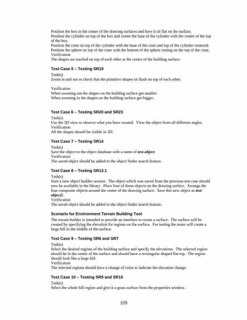
Position the box in the center of the drawing surfaces and have it sit flat on the surface. Position the cylinder on top of the box and center the base of the cylinder with the center of the top of the box. Position the cone on top of the cylinder with the base of the cone and top of the cylinder centered. Position the sphere on top of the cone with the bottom of the sphere resting on the top of the cone. Verification The shapes are stacked on top of each other at the center of the building surface.
Test Case 5 – Testing SR19 Task(s) Zoom in and out to check that the primitive shapes sit flush on top of each other. Verification When zooming out the shapes on the building surface get smaller. When zooming in the shapes on the building surface get bigger.
Test Case 6 – Testing SR20 and SR23 Task(s) Use the 3D view to observe what you have created. View the object from all different angles. Verification All the shapes should be visible in 3D.
Test Case 7 – Testing SR14 Task(s) Save the object to the object database with a name of test-object. Verification The saved object should be added to the object finder search feature.
Test Case 8 – Testing SR13.1 Task(s) Start a new object builder session. The object which was saved from the previous test case should now be available in the library. Place four of those objects on the drawing surface. Arrange the four composite objects around the center of the drawing surface. Save this new object as test-object2. Verification The saved object should be added to the object finder search feature.
Scenario for Environment Terrain Building Tool The terrain builder is intended to provide an interface to create a surface. The surface will be created by specifying the elevation for regions on the surface. For testing the tester will create a large hill in the middle of the surface.
Test Case 9 – Testing SR6 and SR7 Task(s) Select the desired regions of the building surface and specify the elevations. The selected region should be in the center of the surface and should have a rectangular shaped flat top. The region should look like a large hill. Verification The selected regions should have a change of color to indicate the elevation change.
Test Case 10 – Testing SR9 and SR10 Task(s) Select the whole hill region and give it a grass surface from the properties window.
109

Verification The hill region should be covered with a textured grass surface.
Test Case 11 – Testing SR11 Task(s) Zoom in and out to observe what you have created. Verification When zooming out the objects should get smaller. When zooming in the objects should get bigger.
Test Case 12 – Testing SR21 and SR23 Task(s) Use the 3D view to observe what you have created. View the terrain from all different angles. Verification The terrain should be visible in 3D and the elevation changes should be clearly seen.
Test Case 13 – Testing SR8 Task(s) Save the terrain to the terrain database with the name test-terrain. Verification The saved terrain should be added to the terrain finder search feature.
Scenario for Environment Model Building Tool The model builder is intended to provide an interface to combine terrains and object to form an environment. The tester will use the test-terrain terrain and the test-object2 object that was created in the previous scenarios.
Test Case 14– Testing SR1, SR2, SR5.1, SR5.2, SR5.3, and SR5.4 Task(s) Select the test-terrain from the preview window. View it in 3D from the 3D preview window. Add the terrain to the building surface. Select the test-object2 from the preview window. View it in 3D from the 3D preview window. Add 4 of them to the building surface. Verification The terrain and objects should be visible on the building surface
Test Case 15– Testing SR2 Task(s) Position the 4 test-object2 objects at different locations Verification The objects have moved from there original location.
Test Case 16– Testing SR3 Task(s) Select a camera from the object preview window and add it to the building surface. From the camera properties window position the camera at (10,10,10) and pointing at (5,3,2). Verification The camera should be visible on the building surface.
Test Case 17– Testing SR4 Task(s)
110

Select a light source from the object preview window and add it to the building surface. From the light source properties window position the light at (100,100,100). Verification The new light source can be observed in the 3D view.
Test Case 18– Testing SR22 and SR23 Task(s) Use the 3D view to observe the environment. View the environment from all different angles. Verification The terrain and objects should be visible in the 3D view.
Test Case 19– Testing SR24, SR25, and SR26 Task(s) Save the environment to the database with name test-environment. Verification Exit the current environment builder session and start a new session. Load the saved environment from the desktop and check to ensure looks correct.
Environment Needs In order for the EMBT to run the testing system will be running Windows XP or Linux and have to support Java 1.3.1 or later and Java 3D 1.3.1 or later. It is recommended that the testing system have a modern video card which supports OpenGL.
Chapter 9. Assessment Evaluation
Introduction This document presents the results of the functional testing. The Test Case’s are in reference to the Test Case’s defined in the Test Plan 1.0 from Phase 2. Reference: Test Plan 1.0
Test Case Results Summary
Table 3 Test Case Result Summary
Test Case #
Test Unit SR(‘s) Tested Result/Comments
1 Object Building Tool SR12, SR13 Passed
2 Object Building Tool SR17 Passed
3 Object Building Tool SR15, SR16 Passed
4 Object Building Tool SR18 Passed
5 Object Building Tool SR19 Passed
6 Object Building Tool SR20, SR23 Passed
7 Object Building Tool SR14 Passed
8 Object Building Tool SR13.1 Passed
9 Terrain Building Tool SR6, SR7 Passed
10 Terrain Building Tool SR9, SR10 Untested – Feature not
111

implemented and it will be a Future
Requirement
11 Terrain Building Tool SR11 Passed
12 Terrain Building Tool SR21, SR23 Passed
13 Terrain Building Tool SR8 Passed
14 Environment Model Building Tool SR1, SR2, SR5.1, SR5.2, SR5.3, SR5.4
Passed
15 Environment Model Building Tool SR2 Passed
16 Environment Model Building Tool SR3 Untested – Feature not implemented and it
will be a Future Requirement
17 Environment Model Building Tool SR4 Untested – Feature not implemented and it
will be a Future Requirement
18 Environment Model Building Tool SR22, SR23 Passed
19 Environment Model Building Tool SR24, SR25, SR26 Passed
Test Case Result Detail
Test Case 1 – Loading Shapes This test case was successfully passed. All the primitive shapes could be loaded onto the building surface and were visible.
Test Case 2 – Resizing Shapes This test case passed. All the primitives were resized by first clicking in the shape to bring up its properties window, and then using the controls on the properties window the shape could be resized.
Test Case 3 – Changing the Weight and Color This test case passed. All the primitives could have their weight and color changed from the properties window.
Test Case 4 – Moving Shapes This test case passed. All the primitives could be moved with the x, y, and z controls on the properties window. The three different viewing perspectives made it easy to line up and stack the shapes on top of each other.
Test Case 5 – Zooming In and Out This test case passed. From the 3-D viewing tab the scene could be zoomed in and out by holding down Alt then left clicking the mouse and then moving the mouse up and down.
Test Case 6 – Viewing in 3-D This test case passed. From the 3-D viewing tab the scene could viewed from all angles.
112

Test Case 7 – Saving to Library This test case passed. Selecting “Save to Library” from the File menu provide a pop-up window to name the object. After providing a name and clicking the “OK” button the object is saved to the library and is added to the tree that displays a list of the library of objects.
Test Case 8 – Reusing Saved Objects This test case passed. The previous saved object was available to add. Four of the objects were added and moved into position. One improvement would be to have the option to move the added object as a group. At the time of testing the object could only be moved by moving its primitive shapes.
Test Case 9 – Modifying Elevation This test case passed. The tool provided a grid of point to modify. The elevation was adjusted by a slider bar. The values were form 1-100. After selecting an elevation a point on the grid could be clicked and its elevation would change to value of the slider bar. The zero elevation points were black while the higher elevation points were color shades of green; lighter shades of green represented higher elevations.
Test Case 10 – Setting a Texture This test case was untested. At the time of testing there was no way to set a texture for a region. This feature will be future requirement.
Test Case 11 – Zooming In and Out This test case passed. From the 3-D viewing tab the scene can be zoomed in and out by using the mouse.
Test Case 12 – Viewing In 3-D This test case passed. From the 3-D viewing tab the scene could be viewed from any angle.
Test Case 13 – Saving to Library This test case passed. Selecting “Save to Library” from the File menu provide a pop-up window to name the terrain. After providing a name and clicking the “OK” button the terrain is saved to the library and is added to the tree that displays a list of the library of terrains.
Test Case 14 – Adding Objects and Terrains This test case passed. The terrain and objects were successfully added. One improvement could be to have an added object sit flush on the surface. At the current time of test the added object was placed at (0, 0, 0), but the elevation of the terrain was much higher at that point, so the object was underneath the surface of the terrain.
Test Case 15 – Moving the Objects This test case passed. The objects were able to be moved by clicking on them, from the building surface, and using the controls of the provided properties window to move the objects position.
Test Case 16 – Setting the Camera This test case was untested. This feature will be a future requirement.
Test Case 17 – Setting the lights This test case was untested. This feature will be a future requirement.
Test Case 18 – Viewing in 3-D This test case passed. From the 3-D viewing tab the scene could be viewed from any angle.
113

Test Case 19 – Saving an Opening This test case passed. The environment was successfully saved and re-opened.
Chapter 10. User’s Manual
Introduction This document will explain how to set-up and use the Object Building Tool, the Terrain Building Tool, and the Environment Model Building Tool.
Installation and Set-up
Required Software Java 1.4.2 or Later (http://java.sun.com/j2se/1.4.2/download.html) Java 3D 1.3.1 (http://java.sun.com/products/java-media/3D/download.html) Windows 2000 or Linux or Solaris or MacOS (note Linux and MacOS don’t have an official version of Java 3D provided by Sun, but ports are available).
Recommended Hardware X86 compatible processor 1.6 GHz or higher Video card with Opengl support and 32MB of ram
Required Files All the code and executables for running the software is included in “MSE – Esteban Guillen.zip”. To install just unzip to the local machine. The following is a breakdown of the included files: MSE – Esteban Guillen - top level directory |--eob.bat – batch file for starting the Object Building Tool |--etb.bat – batch file for starting the Terrain Building Tool |--emb.bat – batch file for starting the Environment Model Building Tool |--EMBT-0.1 - the eclipse project directory |--bin –directory contains all the .class files for the project |--object-lib – directory for the object library |--terrain-lib – directory for the terrain library |--doc - directory contains all the Javadoc for the project |--src – directory contains all the .java files for the project |--.classpath - eclipse classpath file |--.project - eclipse project file
Object Building Tool
Running To start the applications simply double click on the eob.bat file.
Creating a New Object Once the application is running you can create a new object simply select the New File menu option. The following screen shows the result of selecting the new File menu option.
114

Figure 159 Creating a New Object
There are two tabs; one for building the object, the Drawing View, and other for viewing in 3-D, the 3D View. From the Drawing view we can select objects from the list provided in the Library Objects window. Selecting is achieved by double clicking on an item in the list. Once an item is selected it will appear in the preview window next to the list. The following screenshot show the result of double clicking on the cone list item.
115

Figure 160 Selecting a Shape from the Library
Once an object is selected it can be added to the drawing surfaces. This is achieved by clicking the add button under the preview window. Adding an object will place a 2-D representation of the object in each of the three drawing surfaces. The following screenshot show the result of adding the cone.
116

Figure 161 Adding a Cone Shape
Once the object has been added two the three drawing surface it can be modified. This is achieved by click on the object in any of the three drawing surfaces. Once an object is click a properties window will be provided to allow the object to be modified. The following screenshot show the properties window for the cone.
117

Figure 162 Cone Properties Windw
The properties window will allow you to change the size, location, color, and weight of the cone. The following screenshot show the result of changing the size to a height of 12, a radius of 2, location (2, 2, 2), and color (0.56, 0.51, 0).
118

Figure 163 Modifying a Cone
This object can be viewed in 3-D by clicking on the 3-D View tab. The following screenshot shows the result of clicking on the 3-D View tab.
119

Figure 164 Viewing the Cone in 3D
Once the user is done building the object (note that more objects from the library window can be added) it can be added to the library or saved to disk.
Saving an Object to the Library At any time the object being built can be added to the library. This is achieved by selecting the Save to Library File menu option. After selecting this option a pop-up window will be provided to name the object. After providing the name and clicking the OK button the object will be added to the list provided in the Library Objects window.
Exporting an Object to Disk At any time the object being built can be saved to disk in XML format. This is achieved by selecting the Export to XML File menu option. After selecting this option a save window will be provided to select the location and name of the file to save. The user should provide a .xml extension to the file name.
Opening a Saved Object After starting the application the user can open a previously saved (an XML file) object. This is achieved by selecting the Open File menu option. After selecting that option an open window will be provided to select the object to open. After the file is selected and the open button is
120

clicked that object will be loaded onto the three drawing surfaces. At this point the user has all the options that were provide when starting a new object like adding more objects and modifying the ones that are on the drawing surfaces.
Terrain Building Tool
Running To start the applications simply double click on the etb.bat file.
Creating a New Terrain Once the application is running you can simply select the New File menu option. After selecting the new option you will be provided with the following screen shown below.
Figure 165 Creating a New Terrain
The Terrain builder consists of two main tabs. The first is the Building View which consists of a grid building surface, a height selector, and a preview window. The grid building surface represents points on the surface that is being build. The building surface is an 11x11grid and represents the points of a 10x10 grid surface. Each point is 100m apart in the actual terrain. The points have a color code for representing height. Black represents a height of 0 while light green represents 100m. Heights in between are represented as shades of green with the darker shades the lower elevations and the lighter shades representing the higher elevation. To select a height you just need to move the height selector slider bar in the upper right corner. The selected height will be displayed just above the center of the slider bar. Once a desired height is selected you can click on of the grid point, which will raise that point to height indicated by the slider bar. The grid point will also get colored to the appropriate shade of green. The following figure shows a
121
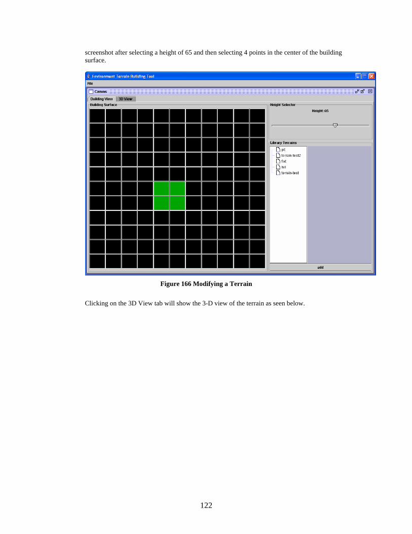
screenshot after selecting a height of 65 and then selecting 4 points in the center of the building surface.
Figure 166 Modifying a Terrain
Clicking on the 3D View tab will show the 3-D view of the terrain as seen below.
122

Figure 167 Viewing the Terrain in 3D
From the 3D View the raise in elevation can be easily seen. Once the desired terrain has been created it can be saved to disk as an XML file or saved to the library. At any point a terrain that has been saved in the library can be added. Doing this will clear any work that has already been done to that point and load the terrain from the library. Loading from the library is accomplished by double clicking on one of the items listed in the Library Terrains window in the Building View tab. After double clicking the list item it will appear in the preview window to the right. Once the terrain is loading into the preview window it can be added to the building surface by clicking the add button under the preview window. The following window shows the result of double clicking terrain-test and adding it to the building surface.
123

Figure 168 Adding a Terrain from the Library
At this point the terrain can be modified just as before.
Saving a Terrain to the Library At any time the object being built can be added to the library. This is achieved by selecting the Save to Library File menu option. After selecting this option a pop-up window will be provided to name the terrain. After providing the name and clicking the OK button the terrain will be added to the list provided in the Library Terrains window.
Exporting a Terrain to Disk At any time the terrain being built can be saved to disk in XML format. This is achieved by selecting the Export to XML File menu option. After selecting this option a save window will be provided to select the location and name of the file to save. The user should provide a .xml extension to the file name.
Opening a Saved Terrain After starting the application the user can open a previously saved (an XML file) terrain. This is achieved by selecting the Open File menu option. After selecting that option an open window will be provided to select the terrain to open. After the file is selected and the open button is clicked that terrain will be loaded onto the building surface. At this point the user has all the options that were provide when starting a new terrain.
Environment Model Building Tool
Running To start the applications simply double click on the emb.bat file.
124

Creating a New Model Once the application is running you can simply select the New File menu option. After selecting the new option you will be provided with the following screen shown below.
Figure 169 Creating a New Envirnment Model
The Environment Model Building tool consists of two main tabs; the Drawing View and the 3D View. The Drawing view provides a top view of the locations of the added objects. The 3D View provides a 3-D view of the added objects and terrain. In the Drawing View objects and terrains are added in the same manner as in the Object Builder and Terrain Builder. When objects are added they are placed in the center of the building surface grid and are represented as a square box. When a terrain is added there is nothing shown on the building surface grid, but in the 3D View the terrain is correctly displayed. Once an object is added to the building surface it can be moved though the properties window. The properties window is provided when clicking on an object in the building surface grid. The following screenshot show the result of adding a tank object and a pit terrain.
125

Figure 170 Selecting a Object and Terrain
The square box in the center of the building surface grid represents the tank object. The tank can be moved by clicking on it and using the controls on the properties window. The following screenshot shows the properties window for the tank.
Figure 171 Object Properties Window
Objects can be moved in any direction. The Y direction is the up direction so it will not show on the 2-D building surface grid.
126
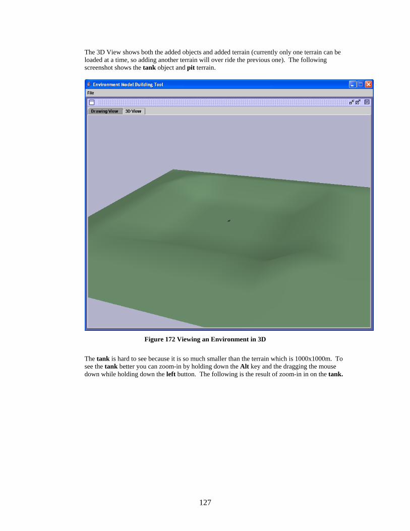
The 3D View shows both the added objects and added terrain (currently only one terrain can be loaded at a time, so adding another terrain will over ride the previous one). The following screenshot shows the tank object and pit terrain.
Figure 172 Viewing an Environment in 3D
The tank is hard to see because it is so much smaller than the terrain which is 1000x1000m. To see the tank better you can zoom-in by holding down the Alt key and the dragging the mouse down while holding down the left button. The following is the result of zoom-in in on the tank.
127

Figure 173 Zooming-in from the 3D View
Exporting a Model to Disk At any time the environment model being built can be saved to disk in XML format. This is achieved by selecting the Export to XML File menu option. After selecting this option a save window will be provided to select the location and name of the file to save. The user should provide a .xml extension to the file name.
Opening a Saved Model After starting the application the user can open a previously saved (an XML file) environment model. This is achieved by selecting the Open File menu option. After selecting that option an open window will be provided to select the environment model to open. After the file is selected and the open button is clicked that environment model will be loaded onto the building surface. At this point the user has all the options that were provide when starting a new environment model.
128

Chapter 11. Project Evaluation
Introduction This document will present a summary of my experiences encountered throughout my MSE project.
Problems Encountered This section describes some of my biggest problems encountered during my MSE project.
Understanding Project Goals One of the first problems I had was to fully understand the goals of this project. At a very high level the project was easy to understand, but once I started to think about some of the details I discovered I needed to ask more questions. After I got a decent understanding of the project goals my next major problem was visualizing how the user would interact with the application. The project was very graphical and has a lot of user interaction, which made the graphical user interface one of the most important parts of the project. I would say designing the user interface was the most challenging parts of the project.
Learning Java3D The Java 3D part of the project posed problems in the beginning. I had a great deal of trouble finding good examples of Java 3D. The Java 3D web site had some information but it was very out of date. After many hours of searching the web I found a few good examples to get me started. I also purchased “Java 3D API Jump-Start”. It is a must read for beginner Java 3D programmers.
Balancing Work The size of this project grew very quickly. At the end there were 3 different stand alone programs. I found it difficult to manage my time between the 3 programs. I always felt like I was neglecting some part of the project.
Features to Implement As mentioned above the project grew very quickly and new feature were constantly being discussed. One of the design goals was to “think big”, that is to think of all the possible features that would be nice to have. It wasn’t practical to implement all the features for my MSE project, so I had to decide which features to implement. In the end my objective was to keep things simple and get everything to work. This approach only allowed about 75% of the features to be implemented, but those that were implemented were done with great care.
Source Lines of Code The first estimate for SLOC was made during Phase 1 and it was estimated to be 2500 SLOC. This estimate was driven from the current prototype and similar examples. I believe this estimate was low because I didn’t have a full understanding of all the features that would be implemented. That estimate was also low because at that point in the project I was planning on just having one large application as opposed to the 3 application that were developed. The next estimate was in Phase 1 and it was estimated to be 4800 SLOC. This estimate was driven from the executable prototype. The executable prototype gave me a better idea of what features would be implemented and how much code it would take to implement those features. The 4800 SLOC was a reasonable estimate to the actual 5372 SLOC. The following is a break down of the SLOC required for each application. Environment Model Builder = 2237 Environment Object Builder = 2315
129

Environment Terrain Builder = 820 Total = 5372 source lines of code
Project Duration The following table show the expected vs. actual completion times for each phase of the project
Table 4 Project Duration
Expected Finish Time Actual Finish Time Phase 1 January 28, 2004 March 17, 2004
Phase 2 May 21, 2004 June 9, 2004
Phase 3 August 15, 2004 July 21, 2004 Both Phase 1 and Phase 2 were delayed. This was due to lack of preparation of the required documents and code. The delay in Phase 1 was mostly because of the prototype. I wasn’t happy with the interface at the end of January, so I waited until March when I was more comfortable with the prototype. The delay in Phase 2 was mainly due to the extended time the Architecture Design took me. It was also delayed because my CIS 844 final project took up much of my time at the end of the semester. Phase 3 was moved up a few weeks. This was driven by the fact that I needed to have my graduate material turned in by July 30. The following lists how much time was spent on each Phase. Phase 1 = 3870 minutes or 65 hours Phase 2 = 5970 minutes or 100 hours Phase 3 = 16410 minutes or 273 hours Total = 438 hours During Phase 1 using the COCOMO model I estimated that the total project would take 840 hours. This estimate was almost twice as long as the actual time. The reason for the over estimate was that COCOMO assumes the project is a large industrial strength project. This assumption adds time for integration testing and interaction between team members. My project was small and didn’t require heavy interaction with team members. During Phase 2 using a bottom-up approach to cost estimation I was able to predict the remaining time for Phase 3 would be 270 hours. This estimate was as close to the actual time of 273 hours that one could hope for. The bottom-up approach allowed me to measure my productivity up to that point in the project. My remaining SLOC estimate made during Phase 2 was very close to the actual and this allowed for my time estimate, which was based of my productivity and remaining SLOC, to be very accurate. The following chart breaks down how much time was spent on each phase.
130
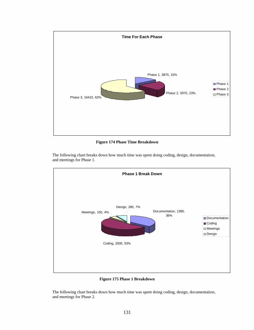
Time For Each Phase
Phase 1, 3870, 15%
Phase 2, 5970, 23%Phase 3, 16410, 62%
Phase 1Phase 2Phase 3
Figure 174 Phase Time Breakdown
The following chart breaks down how much time was spent doing coding, design, documentation, and meetings for Phase 1.
Phase 1 Break Down
Documentation, 1380, 36%
Meetings, 150, 4%
Coding, 2000, 53%
Design, 280, 7%
DocumentationCodingMeetingsDesign
Figure 175 Phase 1 Breakdown
The following chart breaks down how much time was spent doing coding, design, documentation, and meetings for Phase 2.
131

Phase 2 Break Down
Documentation, 2010, 32%
Coding, 2010, 32%
Design, 2040, 32%
Meetings, 270, 4%
CodingDesignDocumentationMeetings
Figure 176 Phase 2 Breakdown
The following chart breaks down how much time was spent doing coding, design, documentation, and meetings for Phase 3.
Phase 3 Break Down
Coding, 5000, 56%Documentation, 3300,
37%
Meetings, 150, 2%Design, 460, 5%
CodingDocumentationDesignMeetings
Figure 177 Phase 3 Breakdown
132

Lessons Learnt This project was a great learning experience for me. I got a taste of what it is like to work on a large project. One of the most valuable lessons I learned was to make your best effort to fully understand what you are trying to build. I found that at some points in the project I had to stop coding and think about design issues. This caused me some frustration as I like to focus on one part of the project as opposed to switching back and forth between designs and coding. I also got the chance to work in a group project setting. Any chance I get to work in a group is beneficial since I will be working in a group setting for the rest of my career. The most valuable lesson I will take away from this project is how thinking through the design will make you think more deeply about what you are building. To be more specific I thought my design was almost complete with just class diagrams. I thought I had a good understanding of how the project would be implemented. But when I started creating a few sequence diagrams I realized I needed to take some more time to think about how the objects would interact.
Future Work Not all the features described in the Vision Document were implemented in this project. The remaining features will be implemented as future CIS 690 project or maybe a MS project. The following documents what feature remain to be implemented.
Robot Builder (New Application/Mode) There is a need for an application to build the actual robots the run in the simulation. This could be a new application or a running mode of the Object Builder. This application would be very similar to the Object Builder, but would need to be tailored to robot specific requirements. The Robot Builder would require new primitive shapes. This could simply be accomplished with wrapping a tag around the current primitives (box, cone, sphere, and cylinder). For example a sensor could be a new primitive and implemented as just a standard box with a sensor tag wrapped around its XML definition. The sensor primitive would also need additional attributes which are specific to the properties of the sensor. Those attributes would also be included in the XML definition.
Object Builder • Moving objects as a group (a select feature). • Making objects a hierarchy of objects instead of just a collection of primitives. • Making the building surfaces scrollable to allow for bigger objects to be created. • Adding the ability to rotate primitive shapes. • Improving the search feature. • Adding a zoom-in and zoom-out feature to the 2D building surfaces. • Being able to set the bounding volume for the object being built (will help with collision
detection).
Terrain Builder • Having the ability to add a texture surface to a region of the terrain (e.g., grassy, rocky,
etc.). • Being able to set the size of the terrain being built instead of having just a default
1000x1000 size. • Improving the search feature.
Environment Builder • Making the building surface scrollable to allow for bigger models to be built. • Allow multiple terrains to be placed on a model instead of the current limit to 1 terrain. • Have a feature to dynamically place all objects on the top of the surface at their location. • Being able to set the size of the model being built instead of having just a default
1000x1000 size.
133

• Adding a mouse over feature on the building surface to identify objects. • Improving the search feature.
References [1] Davison, Andrew. Game Programming With Java and Java 3D.
http://fivedots.coe.psu.ac.th/~ad/jg/: 2004
[2] Fowler, Martin. UML Distilled Third Edition. Boston: Addison-Wesley, 2004.
[3] Horton, Ivor. Java 2 SDK 1.4 Edition. Plainview: Wrox Press, 2002. [4] Lee, Richard & Tepfenhart, William. Practical Object-Oriented Development
With UML and Java. Upper Saddle River: Prentice Hall, 2002. [5] Royce, Walker. Software Project Management. Upper Saddle River:
Addison-Wesley, 1998. [6] Walsh, Aaron & Gehringer, Doug. Java 3D API Jump-Start. Upper Saddle
River: Prentice Hall, 2002.
134