my electric brewery construction
TRANSCRIPT
2014
Charles Tucker
Beckenham Brewery
4/4/2014
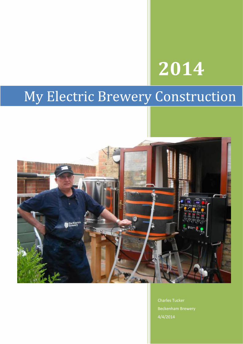
My Electric Brewery Construction

1
Contents My Electric Brewery Construction - Introduction ........................................................................................................... 2
Part 1 - The Control Panel ............................................................................................................................................... 3
Part 2a - The HLT construction........................................................................................................................................ 7
Part 2b - HLT construction continues .............................................................................................................................. 9
Part 3 - Wort Chiller ...................................................................................................................................................... 13
Part 4 - HERMS Pot Reconfiguration ............................................................................................................................. 15
Part 5a - Mash Tun Phase 1 .......................................................................................................................................... 16
Part 5b - Mash Tun Phase 2 .......................................................................................................................................... 21
Part 5c - Mash Tun Supplemental ................................................................................................................................. 22
Part 6a - A start on the Boil Kettle ................................................................................................................................ 24
Part 6b - Completing the Boil Kettle ............................................................................................................................. 26
Part 7 - Brew Stand & other matters ............................................................................................................................ 32
Part 8 - Further modifications to HLT............................................................................................................................ 35
Appendices ................................................................................................................................................................... 39
Appendix A – Original HERMS Pot Construction ....................................................................................................... 39
Appendix B – 24v mag pumps, mounting and power supplies ................................................................................. 42
Appendix C – Constructing a new brew stand .......................................................................................................... 44
Appendix D – Adding additional elements to my pots ............................................................................................. 49
Appendix E – Upgrades to the Control Panel (Elements & Pumps) .......................................................................... 52
Adding extra power supply for the additional elements using a ‘Break-out Box’ ................................................. 52
Adding an auxiliary pump output ......................................................................................................................... 56
Version number 4 – 28 July 2014

2
My Electric Brewery Construction - Introduction This booklet brings together in one binding all the articles I posted on The Home Brew Forum during 2013 and 2014.
It tells the story of how I constructed My Electric Brewery from start to finish and also further modifications I made
in the light of use. The brewery itself is based on the USA Electric Brewery web site, and I thank them for the
inspiration and guidance their site gave me in my own construction.
Please note the booklet is laid out in roughly the same chronological order as I built the brewery. Before copying any
of the build stages it is worthwhile to check the appendices first as I have made many alterations in the light of use
and experience. My latest Control Panel modifications and the Break-out Box are about as far as I want to take my
electrical controls. Besides which, there’s no more space to fit anything else in! My brewing pots have now also been
modified to my satisfaction. So, I consider that My Electric Brewery is now finished. Mind you, I do have two Chugger
pumps on order, so what if I …………………………..???

3
Part 1 - The Control Panel
Being in my early sixties and now retired, I have decided to build my definitive brewery which will probably be the
last one I build. I have determined that this will be the best one I have ever made, picking up from my experience of
building stainless steel pots over the last five years and my home brewing of around 40 years, plus all the knowledge
picked up from the Forum. I have tried to follow best practice and learn from my past attempts at working with
Bergland pots. In this regard, I have decided to follow the build of The Electric Brewery
(http://www.theelectricbrewery.com/) as best I can, bearing in mind their successful clones all around the world. I
have changed their overall plan to cater for my own brewing preferences. For instance, this means incorporating a
separate HERMS set up rather than a combined HERMS/HLT coil and not buying Blichman BoilerMaker pots, which
are incredibly expensive in the UK. The pots I have bought are the high-end stainless steel 100L pots from mrlard, to
which I will add my own taps and elements. This will give me a ½ barrel brewery size. Below I have shown pictures of
the first stage of my efforts, which is building the control panel for the brewery. I will post my pot conversions as I
work on them in later instalments.
This is how all the bits looked before construction:
Working out where to put the receptacles:

4
The holes in the case all cut out ready for mounting the switches and components:
Components mounted:
5
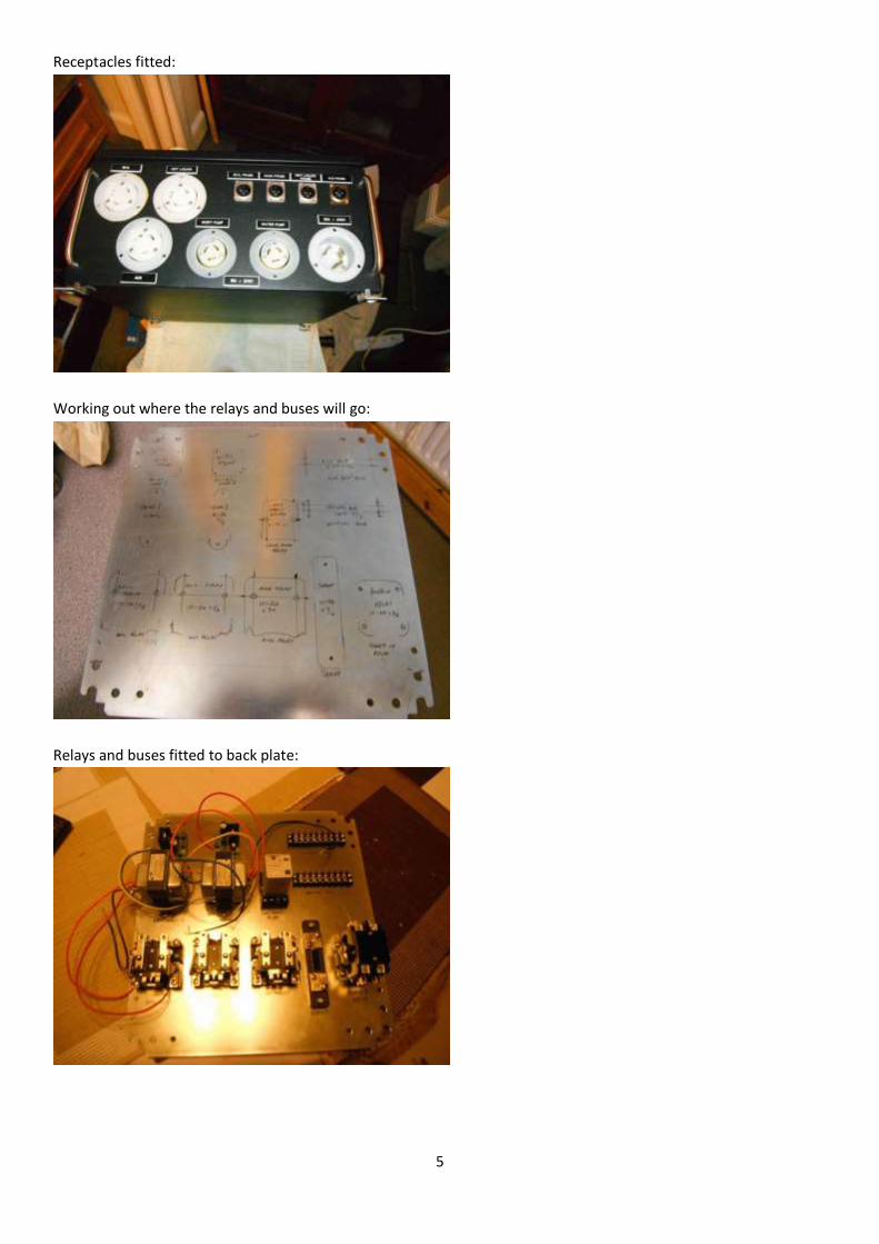
Receptacles fitted:
Working out where the relays and buses will go:
Relays and buses fitted to back plate:

6
All the wiring completed:
And finally, the finished look:
The next stage will be to work on the boil kettle and HLT, followed by the mash tun. I have all the stainless steel
plumbing bits and Starrets that I need, so will start metal bashing next week. Watch out for Part 2 to see how I get
on.

7
Part 2a - The HLT construction I’ve started the build on the HLT now, using one of Homebrewbuilder’s high-end 100L pots
(http://www.homebrewbuilder.co.uk/). I used a 20.4mm Qmax cutter to cut a ball valve hole 3 inches from the
bottom inside of the pot. I am using a weldless fitting to join the valve to the pot and a stainless steel 15mm dip tube
for effective draining. The dip tube was bent to 45 deg using a manual pipe bending tool. The dip tube is joined to
the valve outlet by using a male SS compression stud coupling 15mm x 1/2" BSP, which screws into a female cone
seat union. This method allows me to twist the dip tube into the correct position before tightening the union joint
and also allows the dip tube to be easily removed if I want to clean it out. The picture below shows how the tap is
assembled.
This is what the assembled valve looks like on the inside:

8
The view of the pot from the outside:
Next stages on this pot are fitting a dial thermometer, a sight gauge, a 5500w element and a water input ball valve.
Finally, I will attach a water output "T" connection for the temperature probe. Hopefully, more posts tomorrow.

9
Part 2b - HLT construction continues Started on the second phase of the HLT build today. Apart from the leak testing, it is now nearly complete. I
promised SWMBO that I would not do any more brewery work leading up to Christmas, so the boil kettle will have to
wait until the New Year. I've used the same weldless tap technique to fit the water input valve, as shown below:
Here it is fitted to the HLT:
And here’s the external view

10
I thought I would fit a dial thermometer to imitate the Blichman Boilermaker pots and have used a 2 inch one from
mrlard. The thermometer is superb, but I was not sure that the fittings supplied with it would be leak free, so I have
made a weldless fitting of my own for it, as shown in the bottom of the picture below:
I mounted it about a third of the way up from the bottom, so that it will still record for smaller brews. This is how it
looks from the outside of the pot:
The inside view shows the hole made for the element:

11
I have also added a sight glass, again using a similar weldless method to the taps. The sight glass has yet to be
trimmed and calibrated:
Finally, I just managed to fit the 5500w element before the SWMBO made me pack up for the night. I used the
weldless techniques for the element as shown on The Electric Brewery site:

12
The element will of course need wiring up, but everything has to stop now for Christmas. I also need to fit the
temperature probe T piece. Once the holiday is over I will be working on the boil kettle and posting up my efforts.

13
Part 3 - Wort Chiller
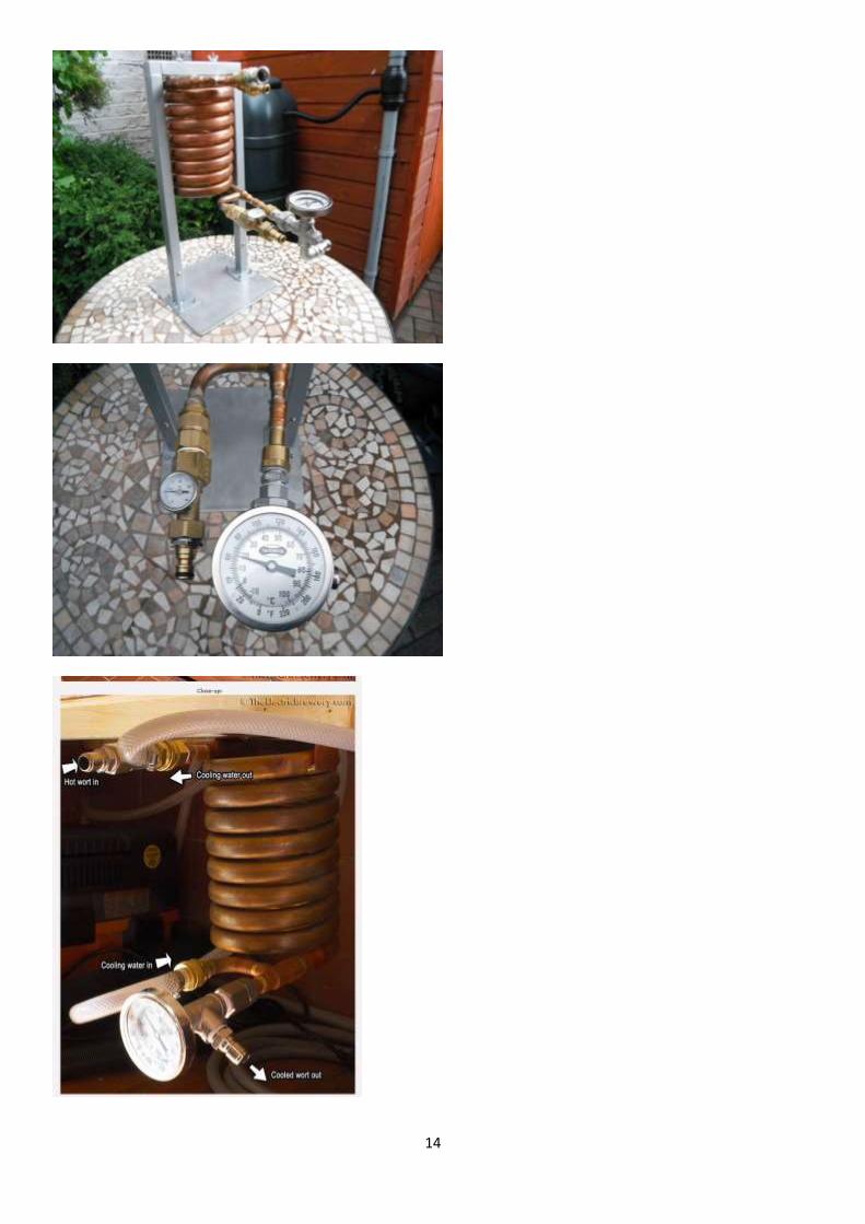
As part of my Electric Brewery build, I have followed the recommendations of “The Electric Brewery” website and purchased the “Chillus Convolutus” counter flow chiller from the US site Morebeer:http://morebeer.com/category/counterflo ... llers.html. This is a robust piece of equipment and very well made. However, the main drawback is that all the connections on it are American NPT and American garden hose threads. So the first thing I had to do was make it compatible with my UK set up. The female beer fittings as supplied are simply soldered on, so after desoldering and cleaning the joints on the chiller, I fitted a pair of John Guest brass ½” BSP – 15mm female stem adapters, part number MW501514N, which are made of DZR brass. To join the adapters to the existing pipes I used 15mm standard Yorkshire Solder Ring Straight Couplers WRAS approved. The existing copper pipe diameter was slightly too small for a snug fit of the coupling, so I used a copper pipe jointer just to flare open the diameter by a millimetre or so. Lead free solder was used throughout. As I wanted to adapt the American garden hose thread to take the standard UK clunk-click hozelock fitting. I bought these quick connecting connectors: http://cgi.ebay.co.uk/ws/eBayISAPI.dll? ... OU:GB:3160. Although the advert says NPT, they are actually ¾” US garden hose connections, which has a coarser thread. I did tell the seller they are wrongly advertised, but I note they are still referred to as NPT. I bought a Water Hose Coupling 3/4 GHT(M)x3/4 FNPT and a Coupling Swivel 3/4 GHT(F)x3/4 FNPT from http://www.tizaro.com to take the quick connects. I also found I needed a Double Female Water Hose Coupling Swivel, again from Tizaro. To make sure I knew the temperature gradients I purchased an inline MAGRA thermometer to record the cold water input temperature (http://www.ebay.de/itm/MAGRA-Thermomete ... OC:GB:3160) and a standard sort of dial thermometer to read the outgoing beer temperature, which was connected into a ½” stainless steel equal cross. I connected this face-up so that it was easier to read. To fit the inline thermometer to the hose fitting I had to buy an ADAPTOR M/F NPT/BSP 3/4" from here: http://www.airlines-pneumatics.co.uk. Of course the chiller needed to be mounted in some way, using its own pre-welded mounting plate on the top, so I decided to make a caddy from 25mm square tube with the appropriate steel core connectors and base fittings (http://www.tradesystems.co.uk/acatalog/ ... ystem.html). I didn’t like the black finish on the tubing, so used a hammered silver spray paint to give it a better look. The base of the caddy needs to be sufficiently strong and well stabilised to take the weight of the chiller and caddy frame, so I mounted it on a piece of Stainless Steel Sheet Grade 304 Mill Finish 3mm thick 250mm x 250mm, using countersunk 5mm stainless steel bolts. The chiller is fixed to the caddy with 6mm wing nuts. The inline thermometer can be removed by unscrewing the swivel hose connector as it is only hand tight against a rubber gasket. The equal cross connector with the dial thermometer is plumbed to the beer output using a 1/2” BSP cone seat union, again making it very easy to remove. After both thermometers and any rubber gaskets have been removed, the chiller can be removed from the caddy and placed into an oven (after rinsing out the coil) for easy drying and sterilisation. I hope the pictures below explain how it all functions.
14

15
Part 4 - HERMS Pot Reconfiguration I previously posted on the Forum the construction of my first HERMS pot, made from a second-hand 10L Baby Burco that I purchased for the grand sum of £6.50 on Ebay.(See Appendix A). I’ve used it twice in brews and it worked well, but now was the time to make it more compatible with my Electric Brewery build. Originally, I used brass hozelock type quick connectors for the wort input and output. The exchange coil was attached to these connectors with plastic John Guest fittings. I decided that these two items in particular needed reworking to be more suitable with my new shiny set up. I have changed the JG fittings to SS cone seat unions. As well as being more robust, it means I can still remove the exchange coil completely for sterilising in the oven. Instead of hose fittings for the wort input and output, I have changed these to stainless steel mini ½” BSP ball valves with camlocks. In addition, the output ball valve has a temperature probe T piece for connection to the PID in the Electric Brewery Control Panel. Once all the hoses and probe are connected, raising the lid to check the water level in the pot could be difficult, so I have fixed a sight glass on the side. The bottom connection of the sight glass uses a 1/2” x 3/8” x 1/2” Tee and inserted into it is another PT100 temperature probe for additional flexibility if needed. As a backup to any temperature probe and PID connections, I have added a dial thermometer. In case I want to use the pot independently of my Electric Brewery, I have also fitted a ½” mini ball valve at the top of the pot for filling and possible recirculation purposes. Finally, the old Burco lever tap has now been replaced with a ½” ball valve with a dip tube. The pictures below show the outside and inside of the reconfigured HERMS pot.

16
Part 5a - Mash Tun Phase 1 Now the Christmas break is over I have started work on the mash tun. I’m using the usual Bergland thermopot and the size is 80L, which is bigger than I have used before, but more in keeping with my completed 100L HLT and proposed 100L boil kettle. All the thermopots I have converted in the past have been built using a fabricated SS 304 skirt or ring within the bottom rim of the pot and I’ve done the same this time. The SS skirt dimensions are 2mm thick with od of 484mm and 75mm high.
I prefer to use a skirt for the drain and ball valve pipe work as I think hacking slices out of the bottom of the thermopots to accommodate the drain fittings is a less desirable approach. The od of the skirt was deliberately chosen to be 1mm less than the exact id of the bottom rim of the thermopot. This means that, due to the manufacturing tolerances of the pot, the skirt initially doesn’t fit! There is an element of flexibility in the stainless steel ring, so the thing to do is to fit as much in as you can – this is about two-thirds of the circumference – and then use a sash clamp to push the ring together and knock it into place with a rubber mallet. Once all the circumference of the ring is partially in, I went round the top of the ring with a club hammer and block of wood and knocked it firmly into position, making sure that the height was the same all the way around the pot and that the pot was level when on a flat surface. (When you invert the pot to do this banging make sure it is resting on a thick blanket and a sturdy work platform.) This way of fitting the skirt means that it is such a tight fit that no bolts or welding are needed to keep it in position. It’s never going to move! Here’s a picture of the skirt fitted and the drain hole drilled ready for the skin fitting drain:

17
As I mentioned in earlier posts of My Electric Brewery construction, I am trying to emulate the design and set up of The Electric Brewery website, without the expense of buying the Blichmann Boilermaker kettles. The Boilermaker pot used as a mash tun in The Electric Brewery has a circulating ball valve, a dial thermometer, and a sight glass. But the Boilermaker is a single skinned vessel and these three items are difficult to fit through the double skin of the thermopot. However, it can be done and I will explain the way I have done it. The gap between the two walls of the thermopot is about 20mm. Two ½” BSP ‘O’ ring nuts from ebay (http://www.ebay.co.uk/itm/LOCKNUT-1-2-B ... 4ab69c74b7) have a combined back to back width of 19mm. A hole wide enough in the outer skin has to be drilled to take the 40mm shim that contains the expansion of the red silicone washer to make the weldless seal. To cover up this hole, a washer wider than the hole is needed. In this respect I had some washers custom made in 1.5mm thick 316 stainless which are 50mm od and 22mm id (http://www.lasermaster.co.uk/easy-order). When the assembled fitting is tightened up on the inside of the pot this large washer is pulled against the outside skin to form a neat finish and covers the hole. A homemade silicon washer behind the back of the large washer ensures a good seal. The large washer that covers the hole has to be bent into a very shallow ‘V’ to take account of the curvature of the pot. I did this by placing it into a vice at exactly the halfway point and giving it a few gentle taps with a hammer. The circulating ball valve and the dial thermometer were both fixed in this fashion. See pictures below:

18
A 5ft sparge hose will be fitted to the circulating ball valve via an elbow and a hose tail. The lower end of the sight glass was fitted in the same weldless manner as the thermometer and recirculating ball valve. The sight glass will have a 3/8” BSP thread cut on it, and this mounts into a ½ x 3/8 x ½ Tee. A temperature

19
probe will be fitted horizontally into the T piece to give an additional measuring point.
The top support for the sight glass is a M6 stainless steel eyebolt. The skin of the thermopot is less than 1mm thick and there is a danger that the bolt could easily pull through the thin skin. What I have done is to fit the bolt to a small plate of stainless steel, and then rivet the plate to the outer wall using stainless steel blind rivets. The plate was bent into a shallow curve to match the pot profile. The fixing doesn’t penetrate the inner wall at all. Some JB Weld around the eyebolt fixing nuts, and along the edges of the plate before riveting, ensures a water tight seal and aids bonding.

20
As on my other pot sight glasses, I have cut a 3/8” thread on top of the sight glass and fitted a round blanking cap loosely to stop any ingress of unwanted matter. Some views of the inside of the pot:
The next phase of this stage will be to fit the output ball valve and test for leaks. More posts on this to follow.

21
Part 5b - Mash Tun Phase 2 Time now to fit the outlet ball valve. Although I am using a ½” ball valve and ½” BSP fittings, the skin fitting used for the drain on this build is actually a 1” BSP fitting. This is only because I had the 1” fitting left over from another build project some time ago and it meant I didn’t need to buy a new ½” drain fitting. I had to chop down the length of the stem by 5/8” with an angle grinder as it was slightly too long. I used a 34mm Starrett to drill the hole through the thermopot base. What marvellous cutters these are – went through so easily. I drilled a 4mm pilot hole through both bottom inner and outer skins first to make sure the hole was centred. The Starrett isn’t long enough to go through both skins, so I had to drill inside and outside of the pot base separately; the pilot hole keeps everything centred. The 1” drain is fitted into a 1” elbow, and then a 9” long 1” BSP 304 barrel nipple screws into this (purchased from here: http://www.ebay.co.uk/itm/1-BSPT-BARREL ... 4ab5e5bc1f). A 1” x ½” reducing socket (http://www.bes.co.uk/products/165a.asp?EPBOE=#14327) screws onto the end of the nipple on the outside of the skirt. The ½” BSP ball valve screws into the reducing socket with the use of a 316 Stainless Steel 1/2" BSP Parallel Nipple 25mm long. The output side of the ball valve is fitted with a ½” BSP T that holds the temperature probe and a camlock connector. All threads, bar one, are sealed using Loctite 55 pipe cord – I find this offers a much better seal than PTFE tape. It was easier to use Rocol Rapidseal on the joint where the skin fitting joins the elbow. The threads were too close fitting to make succesfully with Loctite 55. Two washers were used under the elbow to get the right outlet height and allow very firm tightening against the base. Pictures below show base pipe work fittings before and after assembly:

22
I tested the water tightness of the pot by leaving it filled for several hours. To my horror the bottom joint of the sight glass was rapidly dripping water. Upon dismantling the joint I found that the silicone ‘O’ ring had a split. I replaced the ring and tightened the joint up again and all was well. All I’m going to do now is to fit a stainless steel cupboard-type handle to the pot lid to make it easier to lift on and off. I will post a picture of this when done as I’m waiting for the handle to be delivered from a cheap source in China. Final pictures below show the finished mash tun, complete with false bottom and sparge hose. Next building stage is the boil kettle and I will post up details when construction starts.
23
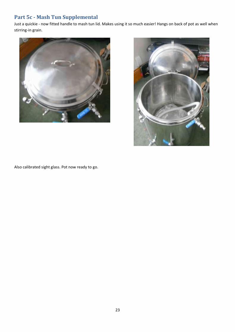
Part 5c - Mash Tun Supplemental Just a quickie - now fitted handle to mash tun lid. Makes using it so much easier! Hangs on back of pot as well when
stirring-in grain.
Also calibrated sight glass. Pot now ready to go.

24
Part 6a - A start on the Boil Kettle With the mash tun completed it was time to start on the boil kettle. As for the HLT, I’m using one of mrlard’s high-end 100L stainless steel pots. The pot will have the same fittings as the HLT – 3 piece ½” BSP ball valve, sight glass, 5500kW element and recirculating ball valve. In addition, I will be fitting a stainless steel hop stopper purchased from here: http://www.ihomebrewsolutions.com/. First thing to do was to mark the pot up for the various holes. A hole was drilled for the dial thermometer and the outlet ball valve using a 3mm drill for a pilot hole and followed by using a tin step drill (http://cgi.ebay.co.uk/ws/eBayISAPI.dll? ... 0728957465). I didn’t use the step drill to fully enlarge the holes, only enough to fit the bolt of a chassis punch – a 20.4mm Q-Max for the ball valve and a 14mm Q-Max for the thermometer. As for the previous pots made for My Electric Brewery, I am using weldless fittings – see my earlier postings for how these are assembled. The pictures below show the three piece ball valve and dial thermometer before and after the holes.
The hop stopper as supplied came with a ½” NPT female compression fitting. I fitted the compression joint onto a male ½” BSP cone seat union. This means I can easily remove the hop stopper for effective cleaning. The dip tube of the hop stopper had to be trimmed by 1” to centre the hop stopper in the middle of the pot. The pictures below show the hop stopper and fittings before and after mounting in the pot.

25
I only had a couple of hours free to work today, so couldn’t complete all I wanted to. My next opportunity to work will be Tuesday or Wednesday, when I hope to fit the recirculation ball valve and sight glass. More posts and photos to follow later in the week.

26
Part 6b - Completing the Boil Kettle The sight glass, recirculation ball valve, output ball valve and heating element are identical to, and are mounted in exactly the same way as, the fittings on my HLT described in earlier posts (viewtopic.php?f=13&t=48378 andviewtopic.php?f=13&t=48416). So I will not dwell on any more detail here. Unlike the HLT, a temperature probe ‘T’ piece on the output valve is not necessary on the boil kettle as the output will be going straight into the wort chiller. None the less, measurement of the temperature in the boil kettle is still required to be fed back into the respective PID in the control panel, so a 4” PT100 probe is mounted horizontally into the sight glass bottom T. When I previously described the HLT build I did not give much information on how the 5500kW element was fitted, so I will first spend a little time on this. In fitting the elements I have used USA electrical parts as they seem better suited to a high-current electric home brewery. The element head and wiring connections are mounted in a weatherproof two gang conduit box purchased from here: http://www.tizaro.com/product/EL1K5B. On the back of the cast aluminium conduit box I drilled a 2.25” hole with a Starrett. Across the back of the box I bolted a square 1mm thick stainless steel plate, the dimensions of which all-round are 3/8” smaller than the box. In the exact middle of this plate I used a 1.25” Q-Max to make a hole concentric with the 2.25” hole in the box. I mounted the plate with stainless steel bolts of the countersunk type to ensure the exterior surface of the plate was flush. Before fitting the bolts and mounting the plate on the box I used JB Weld to make it watertight around the bolts, central hole and plate edges. The Q-Max 1.25” punch was also used to make a hole in the kettle for the element to pass through. The hole on the boil kettle is at 4-1/8” centre from the outside bottom of the pot. This is one inch higher than I mounted the element on the HLT – it needs to be slightly higher to clear the hop stopper described in Part 6a.
To make the weldless fixing of the element I used a high temperature silicon ‘O’ ring (http://www.amazon.com/gp/product/B000FM ... UTF8&psc=1) and a stainless steel shim (http://www.amazon.com/gp/product/B006U2 ... UTF8&psc=1). Pictures below show the element components before and after the mounting:
27
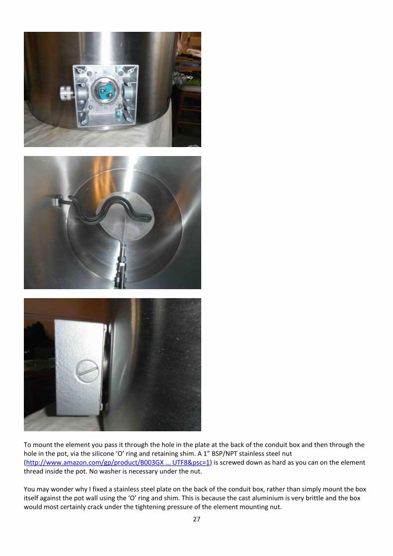
To mount the element you pass it through the hole in the plate at the back of the conduit box and then through the hole in the pot, via the silicone ‘O’ ring and retaining shim. A 1” BSP/NPT stainless steel nut (http://www.amazon.com/gp/product/B003GX ... UTF8&psc=1) is screwed down as hard as you can on the element thread inside the pot. No washer is necessary under the nut. You may wonder why I fixed a stainless steel plate on the back of the conduit box, rather than simply mount the box itself against the pot wall using the ‘O’ ring and shim. This is because the cast aluminium is very brittle and the box would most certainly crack under the tightening pressure of the element mounting nut.

28
The element and the conduit box have a strong tendency to twist as you tighten the element nut. To keep everything square and prevent this a 1.5” AF box spanner is placed over the element head in the conduit box and a block of wood of appropriate height is placed under the conduit box itself while tightening the nut – see pictures below:
After testing for leaks, a bead of transparent silicone sealant can be gunned around the element head in the conduit box as an extra precaution. The conduit box as supplied is a dull grey. I sprayed hammered silver paint on the box to give it a more attractive look. To close the front of the conduit box I bought a brushed-finish stainless steel cover (http://www.amazon.com/gp/product/B0002B ... UTF8&psc=1). The conduit box is supplied with a black foam waterproof seal and this is placed under the cover before screwing the cover in place. The 30A power cable is taken out of the box through an aluminium waterproof gland (http://www.tizaro.com/product/EL4622/hu ... 25-conduit). I put some silicon sealant on the threads of the gland before screwing it into the conduit box. Also make sure that you get blanking plugs to close off any unwanted holes in the box (http://www.tizaro.com/product/EL1JKH/be ... proof-gray). The element power cable is terminated in a NEMA L6-30 male plug which connects into the appropriate control panel receptacle. Here are some more pictures of the element conduit box:

29
Which side of the pot you fix the element is not critical. I placed the HLT element on the right of the pot and the boil kettle element is on the left. This means in my case that both conduit boxes can stick out over the edge of the brew stand and not bash into other pots on the stand. You will note that I have fitted a recirculation ball valve to the pot. This is not really necessary on a boil kettle as the hose from the mash tun when sparging (via the wort pump) could simply dangle over the side of the pot. However, in the stress of brewing I tend to be a trifle clumsy at times and make silly mistakes. What concerned me was that I might accidentally pull on the connecting hose and lose all that lovely wort on the floor. A firm connection with a camlock and ball valve seemed preferable to me! Besides which, the ball valve gives me the opportunity to experiment with a recirculating hop boil as some brewers advocate. If I try this though I would need to replace my hop stopper with a different type of hop filter – the makers of the particular hop stopper I purchased advise that it is not suitable for recirculating the wort in the kettle as this will compact the hops onto the screen and clog it. One last thing I did to the boil kettle (and the HLT) was to fit two stainless steel jubilee clips size 8-12mm to the rear handle. The lids on these pots are pretty big and the question arises what do you do with the lid when you take it off the pot to add something? They are really too large to fit on a table, you don’t want to put them on the floor, and if you drop one it could guillotine your toes! So, the jubilee clips allow me to hang the lid on the back of the pot safely out of the way, as shown below:

30
Final pictures show views of the inside and outside of the boil kettle, with only the sight glass left to be calibrated.

31
Well that’s the boil kettle out of the way. My next posts on My Electric Brewery construction will detail the more mundane ancillary equipment, such as the brew stand, that will be necessary to get my new brewery up and running.

32
Part 7 - Brew Stand & other matters Now that the brew pots and HERMS pot have been made, I will of course need a brew stand to put the pots on and pumps to make it all work. I previously described on the Forum how I have adapted mrlard’s 24v pumps and these will be used with no further changes (viewtopic.php?f=23&t=46600). However, to connect the pumps to the NEMA L6-15 output on the control panel I will need to make up two short extension leads. I could have fitted NEMA male plugs onto the pump power supply leads, but thought that I might want to use the pumps independently of my electric brewery at some point (given the wet weather recently perhaps to bail out a flooded house?). On the more general subject of power, I have a 32A Commando type weatherproof socket mounted on the rear wall of my house, which is wired to a separate consumer unit with RCB, so power is not an issue. A NEMA L6-30 female plug goes into the control panel at one end of the power feed, and a 32A Commando type male plug goes into the wall mounted supply at the other end. As for the brew stand, this needs to take into account my chronic storage facilities. I have no large shed or garage to use as a store or brew house and do all my brewing on the garden patio. This means my set up has to be broken down and be put away when I am finished. All my equipment is stored in my loft. I recently floored all the loft and fitted power and lighting, so I have somewhere to work if I need to. I also enlarged my loft hatch and fitted a pulley system, akin to a dumb-waiter, so that I can easily get things up and down to and from storage. However, a brewing bench is another matter and one strong enough and large enough to hold all my pots and equipment would simply be too big and heavy to get through a loft hatch. So the answer for me was to utilise a multi-functional combination ladder like this: http://www.buydirect4u.co.uk/multi-func ... tAodqVcAgg. I can’t remember where or when I bought my version of this type of ladder, but it was over 15 years ago when they first started to appear in this country. My ladder was imported from the USA and it looks and feels much stronger than the ones I have seen on sale at DIY stores recently. When used as a brew stand the ladder is erected in the platform position. In this mode the general dimensions are 96” length between the bottom legs and 76” length between the top legs. It is 16” wide at the top and 22” wide at the bottom. The height to the top from the ground is 38”. To bridge the rungs along the top I have made a platform from 3/4” inch construction plywood, rebated at each rung position to fit closely and help hold it in place. A 2mm
sheet of aluminium cut to the same dimensions as the platform is screwed on it to give a smooth waterproof surface to stand the pots on. According to the ladder manual, the ladder arranged as a platform is supposed to “take the weight of two men and a tool box”, but the last thing I wanted was for it to collapse with 100L of wort on it, so I have strengthened it by adding a middle support. The support is made from two pieces of 4” x 4” timber braced apart with 2” x 2” battens. A shelf runs from each side of the middle support to the respective side of the legs, where it is fitted to the bottom rung with a ‘U’ bolt. Further bolts connect the shelves to the middle support. The shelf also stops the legs from splaying. The shelf is very handy for standing the pumps and wort chiller on. I bought all the wood and shelving as off-cuts and the whole lot cost me less than £20. Wood and shelves are varnished with yachting varnish for protection. It only takes a couple of minutes to put up or take apart the brew stand. The ladder is stored folded in my small garden shed and the other bits in the loft. Pictures below show the parts before and after assembly.

33
I did a dummy run today with all the pots, pumps and wort chiller in position along with the control panel. The large plastic pot to the right is the cold liquor tank. I first put the mains water into this via an active carbon filter for treatment. I add potassium metabisulphite to remove the chlorine and chloramines then add whatever brewing salts I need before pumping the water into the HLT for heating up. This graduated plastic tank holds 100L and was given to me as surplus unused equipment by a photo developing factory that was closing down – it was originally made for holding developing fluid, but it was never taken out of its cardboard delivery box. I fitted it with a ball valve and dip tube. Here are some pictures of the dummy run.

34
The mount for the control panel is a Plasma TV stand (http://www.amazon.co.uk/gp/product/B00D ... UTF8&psc=1). It can hold 35g, so easily supports the 17.5kg weight of the control panel.

35
Part 8 - Further modifications to HLT I previously posted in instalments the construction of My Electric Brewery and since completing the project I have made further changes in the light of using it. The first alteration arises because of the long length of the combined ball valve and T piece temperature probe on the output of the HLT. This is not a problem when the HLT pot is in situ, but has caused difficulties when trying to store the pot. I do not have much storage space in my property, so all my brewing pots are stored in the loft. Despite recently enlarging the size of the loft hatch, I found that the length of the output arrangement, plus the diameter of the pot, was too long to clear the opening of the loft. I therefore have rebuilt the connection of the ball valve to the HLT utilising a male cone seat union. This means that the tap assembly and attached temperature probe T piece can be easily unscrewed for storage purposes. Disconnected, this has given me 6.5 inches less pot width to try and squeeze into the loft - it just about fits through the loft hatch now! The new ball valve arrangement is shown below:
36
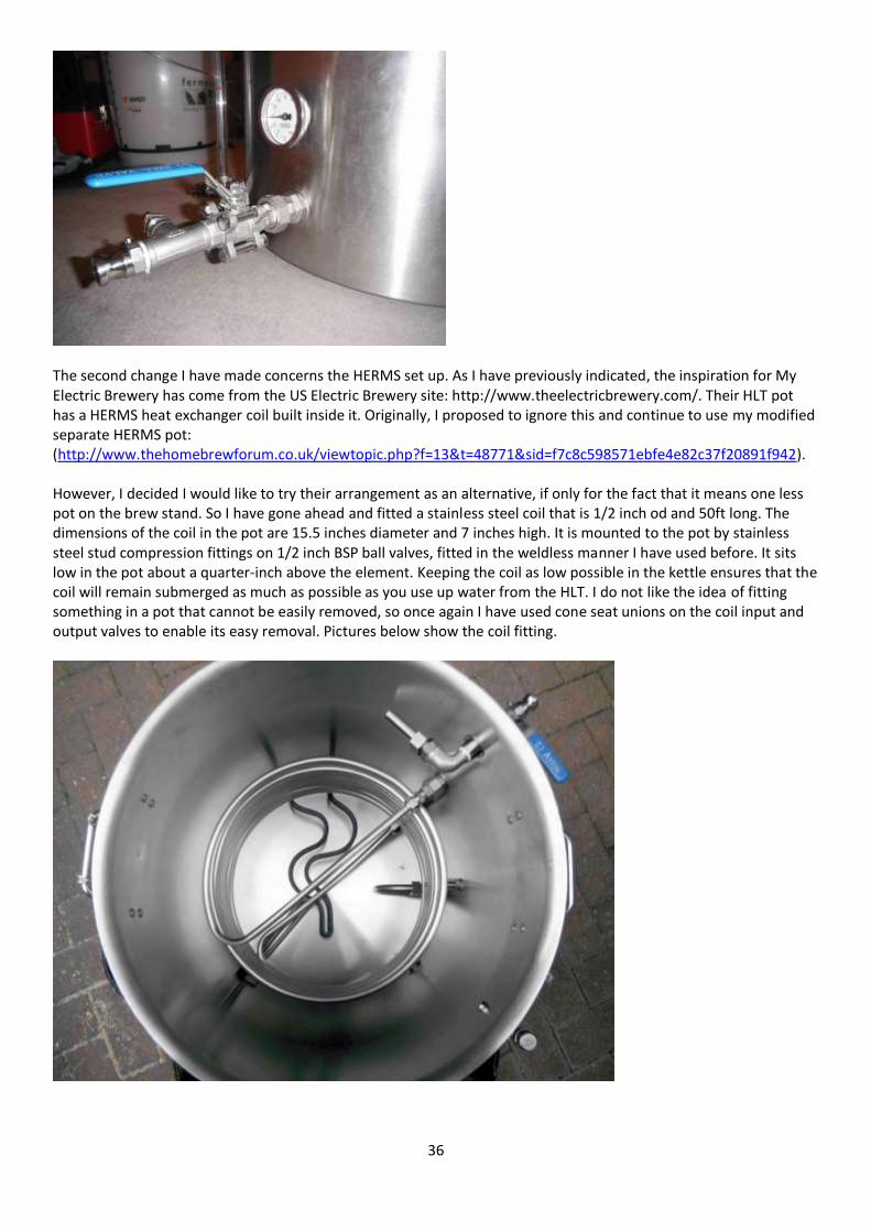
The second change I have made concerns the HERMS set up. As I have previously indicated, the inspiration for My Electric Brewery has come from the US Electric Brewery site: http://www.theelectricbrewery.com/. Their HLT pot has a HERMS heat exchanger coil built inside it. Originally, I proposed to ignore this and continue to use my modified separate HERMS pot: (http://www.thehomebrewforum.co.uk/viewtopic.php?f=13&t=48771&sid=f7c8c598571ebfe4e82c37f20891f942). However, I decided I would like to try their arrangement as an alternative, if only for the fact that it means one less pot on the brew stand. So I have gone ahead and fitted a stainless steel coil that is 1/2 inch od and 50ft long. The dimensions of the coil in the pot are 15.5 inches diameter and 7 inches high. It is mounted to the pot by stainless steel stud compression fittings on 1/2 inch BSP ball valves, fitted in the weldless manner I have used before. It sits low in the pot about a quarter-inch above the element. Keeping the coil as low possible in the kettle ensures that the coil will remain submerged as much as possible as you use up water from the HLT. I do not like the idea of fitting something in a pot that cannot be easily removed, so once again I have used cone seat unions on the coil input and output valves to enable its easy removal. Pictures below show the coil fitting.

37
I know that there has been quite a lot of debate on the Forum as to whether a large HERMS coil in a large pot can be as effective as perhaps a small coil in a domestic kettle. The key concern being whether the temperature response time is too slow in a large set up. Anyhow, I thought I would give it a try. If I find the arrangement does not work to my satisfaction over time I will take the coil and ball valves out and close the holes off neatly with blanking plugs. Since fitting the coil I have carried out one brew with it and so far it seems to work well with no excessive delay in terms of temperature control. The last refinement to the HLT is the fitting of an additional element - you can just see it to the left under the coil in the interior photo of the pot above. I found that, due to its size, the pot was taking a long while to get to

38
temperature. I bought one of angelhomebrew’s 2400w stainless steel elements and it has really made a difference to rise times. I have since made the extra element modification to the boil kettle as well. Fitting the extra elements to the HLT and Boil Kettle has meant I had to make some alterations to the Control Panel. These are explained further in Appendix D.

39
Appendices
Appendix A – Original HERMS Pot Construction Just recently I asked the forum for advice on building a HERMS and was grateful for the response, so I thought I would post up my efforts. My chosen vessel is a Baby Burco 10L water heater, as I managed to pick up one of these very cheaply on ebay - it cost me the grand sum of £6.50! As cheap as it was, it was in a bad state. The element was corroded, it was badly scaled, the lid knob was cracked, and it was missing the correct temperature dial. The washer in the tap was also faulty causing the tap to constantly dribble. The pics show the poor thing as picked up:

40
After a good clean, descale and a new element this is now what it looks like: I had a spare lid knob so replaced the broken one, and I have ordered a new control knob. A new tap washer was made up from 4mm silicon sheet. As it happens, I also had a spare 2.75 kW Burco element as well - it was given to me when I purchased a F33L model many years ago. A quick check on the wiring and thermostat showed all was now in working order. So on with the HERMS build. I had 4 metres of 10mm copper coil left over from an immersion cooler I made, so I wound this around an Ikea utensil holder to get a nice tight shape. The coil is 155mm diameter and 130mm high, with about 7.5 turns. I have used JG 1/2" female push fit fittings to hold the coil to the lid, so that I can easily remove the coil to make sure the inside is dry after rinsing by placing it in the oven. It was suggested to me that any residual water or mash liquor in the copper coil could lead to verdigris forming, which I believe is poisonous. The internal dimensions of the 10L Burco are very similar to the size of a 6L therompot, which other members have often used for a HERMS. The stainless steel fittings on the lid are 1/2" BSP 50mm parallel nipples fitted either side of the lid with 1/2" BSP SS nuts. Under each nut I have used a stainless steel 1/2" BSP Dowty washer. My connections to the heat exchanger are by 1/2" BSP CK brass female hose couplings. The pictures I hope explain the construction:

41
It's all been tested for water tightness, so the next step is to train my PID. I'm looking forward to using it for my next brew.

42
Appendix B – 24v mag pumps, mounting and power supplies Mrlard at homebrewbuilder.co.uk does some jolly nice 24v mag drive pumps which have a really good output, also 12v ones of the same size. I guess the only slight difficulty with these is that they have no mounting points. This can be particularly difficult if you wish to mount a valve on the pump output to control flow. After looking at the recommendations for March 809 mag drive pumps, I've come up with my own mounting system for 24v mag pumps. I've used brass ring clips of various sizes, with brass backplates with backplate extensions - cut down if needed. As the pumps have a magnetic drive I thought any mounting material must be non-magnetic, hence my choice of brass and stainless steel. I've used a mixture of 28mm, 54mm and 67mm brass ring clips from BES (http://www.bes.co.uk/). Where ring clips and extensions don't quite work I've cut down stainless steel M10 studding with M10 bolts as appropriate. The circumference on the 54mm ring had to be increased slightly for the rear of the pump and the 28mm ring clip on the input was a bit loose, so I cut a ring from silicon tubing to pack it out. Pictures of my pump stand follow, showing the water and wort pumps and their mounting system. You will note I've kept the pumps horizontal, with the output higher than the input. This is the advice given when mounting March pumps to ensure efficient priming with no air blockages. The wood for the pump stand was a piece of old pine window sill that was sanded clean and varnished.

43
I thought you might also be interested in my 24v power supply. I use a 24V DC 72W Constant Voltage Power Supply from Litecone which is sold as a LED driver: To make sure that it is protected from beer and water sloshing about I have mounted it in a "Lock and & Lock" Rectangular Bacon Food Container. The power output cable had to be cut to fit in the box and rejoined using a terminal block. The mains plug on the input cable is removed to pass the cable through.
After drilling suitable holes for the input and output cables, two cable glands are used to get a watertight seal. http://www.litecone.co.uk/PBSCProduct.a ... D=10324237. See pictures below:

44
Appendix C – Constructing a new brew stand In Part 7, I detailed how I converted a multi-shape ladder into a brew stand. Although it worked reasonably well, it was far from purpose built and left the pots too high to access without using a small step ladder. So I decided to make a proper brew stand made from planed softwood. I wanted the kettles to be up around arm height when standing up to make adjustments easy. The pumps work best when placed as far below the kettles as possible, so I have built a second shelf below. I wanted the brew stand large enough to hold my 100L HLT, 100L boil kettle, 80L mash tun, and 10L Herms pot comfortably. This resulted in a stand that is 2M wide, 900mm high, and 600mm deep. I have used the brew stand design shown on The Electric Brewery web site as the basis, but significantly changed it to suit my own particular brewing circumstances. It was built out of inexpensive planed softwood that is typically used in construction, making use of off-cuts where possible. Hex bolts/nuts/washers, lag screws, and regular soft wood screws were used to hold it all together. All hardware is stainless steel where possible. It is mounted on four industrial nylon castors to enable easy moving if necessary. The following materials were used: Nuts & bolts 10 x 8g (4mm) A2 stainless steel wood screw pozi countersunk 60mm 100 x 8g (4mm) A2 stainless steel wood screw pozi countersunk 40mm 30 x M10 A2 - 304 stainless steel full nut 60 x A2 stainless steel Form G washers - M10 flat washer 30 x 150mm x M10 (10mm) A2 stainless part threaded hexagon head bolt 5 x 130mm x M10 (10mm) A2 stainless coach screw hexagon head lag bolt 12 x 100m x M10 hexagon bolts, nuts and washers 16 x 50mm x M8 (8mm) A2 stainless coach screw hexagon head lag bolt 4 x 75mm industrial swivel castors with nylon wheels (two braked). Each castor has 110kg capacity. Planed softwood (mm) (All dimensions nominal except for length which is actual) 5 @ 50 x 150 x 1910 planed softwood 4 @ 50 x 150 x 600 8 @ 50 x 100 x 784 34 @ 25 x 125 x 600 4 @ 50 x 50 x 1910 The dimensions given above are standard nominal sizes for softwood planed on four sides. The actual sizes are different from the nominal sizes. For example, a 50 x 150 has an actual size of 45 x 145, a 50 x 100 has an actual size of 45 x 95, a 25 x 125 has an actual size of 21 x 120, and a 50 x 50 has an actual size of 45 x 45. All the parts ready for assembly, plus a very interested dog:

45
The brew stand is bolted together and both the top and bottom shelves are detachable. This means I can break it down and ‘flat-pack’ the stand for storage if needed. Working out the correct height is critical. You must take into account the overall height of the castors and the thickness of the top shelf planking, which in my case was 21mm. So this meant my legs had to be 784mm high to give the finished height of 900mm. Two of the 50 x 100 x 784 pieces are first glued and screwed together with two 60mm pozi screws. Do this four times to form each of the four 95 x 90 legs. Gluing the legs together:
The 50 x 150 boards are bolted to the outsides of these legs to form the shelf edges. Drill 10mm holes for the hex bolts to pass through and use flat washers on both sides (if too tight use an 11mm drill). Tighten using a socket wrench. The four 130mm lag screws (not hex bolts) are installed into the 50 x 150 top middle cross beam. A cross beam is not used on the bottom shelf as the likely load weight is not significant. Drill 7mm pilot holes at least 110mm deep first for the lag screws otherwise the wood may split or the screw may snap. Tighten using a socket wrench and remember to use a flat washer.
Bolting the long sides to the legs, making sure all the joins are square:

46
The frame assembled prior to fitting the shelf battens and shelf boards: The 50 x 50 x 1910 timber is bolted to the long sides top and bottom as battens for the 25 x 125 x 600 shelf timber. Fix the 50 x 50 x 1910 shelf battens to all four long side boards using the M10 x 100mm hexagon bolts (three per batten). The bolts holding the battens to the long sides are fitted with the nuts on the outside of the frame. This makes it easier to tap out the bolts to remove the shelves as one piece. Once the frame is completed, install the 25 x 125 bottom and top shelf pieces using 4mm x 40mm pozi wood screws. Drill a clearance hole in the shelf pieces and 2.5mm pilot holes in the battens to avoid splitting the wood. Seventeen boards are used for each shelf, but the bottom shelf will need the two pieces at each end to be shaped to go round the legs.
Views of underneath top and underneath bottom showing battens for shelf boards:
Fixing the castors: Drill 4 holes on each of the frame bottom corners for each of the four castors. Use a 5mm pilot drill first, and then screw the castors on with the M8 lag bolts using a socket wrench.

47
Fully assembled prior to varnishing: The stand is finished with three coats of satin exterior varnish to give it a durable and waterproof seal. To protect the top when in use, I bought from Ebay four rubber playground tiles 500 x 500 x 25 as heat mats. These are most important under the Boil Kettle as the temperature reaches boiling and could scorch the wood.
Picture of playground mats, top and bottom:
The finished and varnished brew stand, and the dog giving his approval:

48
As the brew stand is rather too large and heavy to store indoors (it weighs 96kg), I have purchased a heavy-duty custom made cover from Kover-it (http://www.kover-it.co.uk/) to go over it. The cover is about 50mm shorter than the actual height of the bench to allow for the wheels to move without catching the cover. The brew stand covered and protected from the weather. And don’t worry - the dog isn’t under the cover!:
This last picture shows all the brew pots on the stand. From left to right we have the boil kettle, the mash tun, the 10L HERMS pot, the hot liquor tank (this has an internal 1/2 inch x 50ft herms coil should I need to use it). On the bottom shelf are shown the CFC and the wort and water pumps.

49
Appendix D – Adding additional elements to my pots I recently fitted extra 2400w elements to both my HLT and boil kettle. The elements are SS from angel home brew. The thread on these elements is 1inch BSP and they are supplied with a cable and shroud. I initially fitted the elements as supplied and they worked fine, but I didn't like the way the shroud and cable stuck out from the pot, so I ditched the supplied shroud and used the same fitting technique I used for the existing 5500w elements. In addition, rather than have a fixed power cable sticking out from the element mounting box, I fitted Neutrik Powercon sockets to both the 2400w and 5500w mounting boxes. Powercon 20A socket fitted to 2400w element box: Internal view showing wiring to 2400w element:
I didn't use the earth tag on the element itself as the element outer is in physical contact with the mounting box. I therefore used the earth mount screw in the box itself. Exterior view of element mounting box with SS lid screwed on. There is a gasket under the lid to keep it watertight:
Mounting box for the 5500w element using a Powercon 32A socket:

50
Power leads that plug into the 20A and 32A sockets. I used heat shrink cable to make the 32A plug waterproof. The 20A plug is fitted with the optional rubber boot that is available. Both leads plug into my control panel:
Views inside the HLT and Boil Kettle of the elements:
In fitting the elements I have used USA electrical parts as they seem better suited to a high-current electric home brewery. The element head and wiring connections are mounted in a Bell weatherproof two gang conduit box purchased from here: http://www.amazon.com/Bell-5341-0-Weath ... oof+Box%2C. I also bought the stainless steel blanking plates from the same source: http://www.amazon.com/gp/product/B0002B ... UTF8&psc=1. Make sure you get the sealing gaskets: http://www.amazon.com/Sigma-Electric-14 ... ox+gaskets On the back of the cast aluminium conduit box I drilled a 2.25” hole with a Starrett. Across the back of the box I bolted a square 1mm thick stainless steel plate, the dimensions of which all-round are 3/8” smaller than the box. In the exact middle of this plate I used a 1.25” Q-Max to make a hole concentric with the 2.25” hole in the box. I mounted the plate with stainless steel bolts of the countersunk type to ensure the exterior surface of the plate was flush. Before fitting the bolts and mounting the plate on the box I used JB Weld to make it watertight around the bolts, central hole and plate edges. The Q-Max 1.25” punch was also used to make a hole in the kettle for the element to pass through. To make the weldless fixing of the element I used a high temperature silicon ‘O' ring (http://www.amazon.com/gp/product/B000FM ... UTF8&psc=1) and a stainless steel shim (http://www.amazon.com/gp/product/B006U2 ... UTF8&psc=1). To mount the element you pass it through the hole in the plate at the back of the conduit box and then through the hole in the pot, via the silicone ‘O' ring and retaining

51
shim. A 1 inch BSP stainless steel nut (supplied with the 2400w element) is screwed down as hard as you can on the element thread inside the pot. No washer is necessary under the nut. Of course you have to make sure that you have enough “ampage” capability in your power supply to control, what in my case, is a total element output of 7900w in each brew pot. This could be over 34 amps. My control panel is only rated up to 30 amps, so I have built a break-out relay and switch box with its own SSR to provide the extra power. The break-out box is connected to the control lines for the element relays and SSR triggers inside the control panel. I have written details on the break-out box in Appendix E.

52
Appendix E – Upgrades to the Control Panel (Elements & Pumps)
Adding extra power supply for the additional elements using a ‘Break-out Box’
I mentioned in Part 8 that I have fitted extra elements to the HLT and Boil Kettle. To control the extra 2400w element in tandem with the existing 5500w element in the pots, I have constructed a stand-alone relay and switch box with its own 25 amp SSR. This is connected to control lines in the control panel via two Speakon 4 way panel connectors - one for the HLT and one for the Boil kettle. The result is that the extra 10 amps I need for each new element is not running through the control panel - I was concerned that it would overload the control panel at over 32 amps with both elements on. See pictures below of the new switch/relay box:
Above left shows the power outputs and above right shows the Speakon control line inputs. Picture shows power input. All power sockets are NEMA L6-15 twist lock connectors.
The switches and neon indicators were chosen to match those on the control panel.

53
Above pictures show the Speakon 4 –way output sockets on the control panel. To connect the control panel and switchbox together, I bought two ready-made leads - NL4FX Speaker Cable 4 core 2.5mm Speaker Cable 3m - from professionalaudiocables.co.uk. They come with the appropriate twist lock plugs already connected. To stop ingress of dust and water into the sockets I use Speakon dummy plugs when the sockets are not in use. I had to do some modifications to the switches and wiring in the case as well. To provide a 12v control line for power relays in the switchbox I fitted a small 12v x 1a psu on the right hand side of the control panel case.
This was wired across the existing 240v AC positive and negative buses, with the 12v output going to the Speakon outlets via an extra switch block (NO type) on both the element select switches inside the control panel.

54
Also connected to the Speakon outlets were the SSR control outputs of the PID controller SYL-2352. This provides a 12V DC signal that can control up to 5 SSRs in parallel. The picture shows the Speakon outlets inside the case. The two diagrams below show how the relays in the switch box are connected up. SSR trigger relays:

55
Power relays:

56
Adding an auxiliary pump output
I added an Auxiliary Element switch and output to the control panel when I first built it. However, after using the control panel several times I thought it would be useful to have an auxiliary pump output as well, so that I could control three pumps. This would enable me to have a pump to use for my cold liquor tank. This required punching two extra 22mm holes in the control panel case door – one to take the green neon ‘on-off’ indicator and one for the ‘on-off’ switch itself. The new switch and neon positions:
As for the pump outlet socket, there wasn’t enough room to fit another L6-15 receptacle, so I decided to use a Powercon True1 weatherproof 16 amp connector (NAC3FPX). Like the L6-15, it has a twist-lock operation. The pumps and heaters are connected to a safety interlock inside the control panel. This prevents the panel from becoming live until all the heater switches and pumps are switched to the off position. Fitting an extra pump switch meant that I had to extend the interlock wiring to accommodate the new switch. The new bottom and front panel layout are shown below: