mvbe databank
TRANSCRIPT

Building MSC.Mvision Databanks

CorporateMSC.Software Corporation2 MacArthur PlaceSanta Ana, CA 92707 USATelephone: (800) 328-4672Fax: (714) 784-4056
EuropeMSC.Software GmbHAm Moosfeld 1381829 Munich, GermanyTelephone: +(49) (89) 431 987 0Fax: +(49) (89) 436 17 16
Asia Pacific
MSC Software Japan Ltd., Asia-Pacific OperationsShinjuku First West 8F23-7 Nishi Shinjuku1-Chome, Shinjuku-KuTokyo, JAPAN 107-0052Main Phone: (81) 3 6911-1200Fax: (81) 3 6911-1201
Worldwide Webwww.mscsoftware.com
Disclaimer
MSC.Software Corporation reserves the right to make changes in specifications and other information contained in this document without prior notice.
The concepts, methods, and examples presented in this text are for illustrative and educational purposes only, and are not intended to be exhaustive or to apply to any particular engineering problem or design. MSC.Software Corporation assumes no liability or responsibility to any person or company for direct or indirect damages resulting from the use of any information contained herein.
User Documentation: Copyright 2006 MSC.Software Corporation. Printed in U.S.A. All Rights Reserved.
This notice shall be marked on any reproduction of this documentation, in whole or in part. Any reproduction or distribution of this document, in whole or in part, without the prior written consent of MSC.Software Corporation is prohibited.
MSC is a registered trademark and service mark of MSC.Software Corporation. Mvision and Patran are registered trademarks of MSC.Software Corporation.
MSC.Enterprise Mvision, MSC.Mvision, MSC.Mvision Builder, MSC.Mvision Evaluator, MSC.Mvision Pro, MSC.Patran and MSC. are trademarks of MSC.Software Corporation.
NASTRAN is a registered trademark of the National Aeronautics and Space Administration. MSC.Nastran is an enhanced proprietary version developed and maintained by MSC.Software Corporation. All other products are identified by the trademarks of their respective companies or organizations.
We acknowledge the use of MKS Toolkit® (NuTCRACKER® Workstation and NuTCRACKER® Server), copyright 1995 - 2006, MKS Software Inc. All rights reserved.
MV*V2006*Z*BLDG*Z*DC-USR
C O N T E N T SBuilding MSC.Mvision Databanks
1Introduction � Overview, 10
� Hardware and Software Usage, 11❑ System Requirements, 11
❑ Software Usage, 11
� MSC.Mvision Databanks, 12❑ MSC.Mvision Databanks Export, 13
❑ MSC.Mvision Databank Files, 13
� MSC.Mvision Materials Information System Products, 22❑ MSC.Mvision Software, 22
❑ MSC.Mvision Databanks, 22
❑ Overview of MSC.Mvision Product Line., 24
� Technical Support, 25
2Planning Databanks
� Overview, 28❑ Using Databank Standards, 28
� Building Databanks Process, 29
� Building Databanks Checklist, 31❑ Planning Databanks (Chapter 2), 31
❑ Designing Databanks (Chapter 3), 31
❑ Creating Databanks (Chapter 4), 31
❑ Revising Schemas and Databanks (Chapter 5), 32
❑ Creating Customization Files (Chapter 6), 32
� Organizing the Project, 33❑ Getting Started, 33
❑ Defining the Project, 33
❑ Defining User Profile, 34
❑ Planning the Project, 35
� Accessing MSC.Mvision Builder, 36❑ Starting MSC.Mvision with Command Line Options, 36
� Disk Space Management, 38
3Designing Databanks
� Overview, 40
� Understanding MSC.Mvision Terms, 41❑ Understanding Terms, 41
� Creating Schemas (Define Files), 48❑ Guidelines, 48
❑ Design Considerations, 48
❑ Naming Define Files, 52
� Defining Attributes, 53❑ Attribute Command, 53
❑ Table Attributes, 55
❑ Creating Attributes, 60
❑ Naming Attributes, 60
� Defining Relations, 66❑ Relation Command, 66
❑ Naming Relations, 67
❑ Hierarchy Relations, 67
❑ Source Relations, 67
❑ Data Relations, 68
❑ Creating Relations, 69
� Defining the Hierarchy, 71❑ Hierarchy Command, 71
❑ Creating Hierarchy, 71
� MSC.Mvision Unique Identifier, 73
4Creating Databanks � Overview, 76
� Initializing Databanks, 76
� Constructing Data Input Files, 78❑ Overview, 78
❑ Data, 80
❑ Metadata, 82
❑ Footnotes, 83
� Processing Input Files, 84❑ Matching for Loading via Input Files, 85
❑ Merge Feature, 88
❑ Merge Keys, 88
� Creating Prototypes, 89
� Data Loading Methods, 90❑ Interactive Builder, 91
❑ Command Line Builder, 94
❑ Spreadsheet, 94
❑ Session Files, 97
❑ EXPRESS Utilities, 98
❑ Database Programmatic Interface (DPI), 100
❑ Diagnostic Messages, 100
❑ Loading Tables, 102
❑ Loading Figures, 108
� Saving Databanks, 120
5Revising Schemas and Databanks
� Overview, 124
� Reviewing and Revising Schemas, 125❑ Listing Relations and Attributes, 125
❑ Displaying and Modifying Hierarchy, 125
� Revising Attributes, 127❑ Listing Attributes, 127
❑ Editing Attributes, 128
❑ Adding Attributes, 130
� Modifying Data, 134❑ Adding New Data, 134
❑ Set Default Namespace, 145
❑ Revising Units, 146
❑ Deleting Data, 146
� Rebuilding Databanks, 148
6Creating Customization Files
� Overview, 150
� Form Definitions File, 151❑ Constructing the Form Definitions File, 151
❑ Wildcard Forms, 156
� Units Conversion File, 157
� Mapping Files, 158
� Disclaimer File, 159
� Index File, 160
� Online Help, 161
ABuilding Databanks � Builder Functions, 164
❑ New Databank, 165
❑ Read Data, 166
❑ Write Data / Write Databank…, 166
❑ Save Databank / Save Databank As…, 166
❑ Modifying a Databank, 166
❑ SessionFile Playback, 168
❑ Log Files, 169
� Building Databanks - Tutorial, 170
BBatch Builder Programs
� Batch Builder Programs, 176❑ mvbatchbuilder, 177
❑ mvclb, 188
❑ mvdump, 189
❑ mvdups, 189
❑ mvindex, 190
� MSC.Mvision PCL Commands, 191❑ Builder Session File Commands , 191
� DPI Functions, 198
� EXPRESS Translators, 200❑ mvision_to_express, 200
❑ express_to_mvision, 201
❑ Merging Data, 202
CShareware � Overview, 206
� Using Shareware, 207❑ Utilities, 207
❑ Scripts, 207
❑ External Functions, 207
❑ Examples, 208
❑ Miscellaneous, 208
� MSC.Mvision PCL, 209
� File Listing and Index, 210❑ bin/;, 210

❑ utilities/, 210
❑ scripts/, 212
❑ external_functions/, 212
❑ example/, 213
❑ misc/, 213

MSC.Mvision Builder and Evaluator 2002 Installation Guide
1 Introduction
� Overview
� Hardware and Software Usage
� MSC.Mvision Databanks
� Technical Support
10
OverviewMSC.Mvision Builder and Evaluator provides engineers with ready access to the comprehensive materials information required for predictive engineering. MSC.Mvision Builder and Evaluator includes sophisticated, easy-to-use tools for the visualization and selection of materials alternatives, and allows for modeling and direct transfer of these properties to engineering simulation tools.
MSC.Mvision Builder is a module of the MSC.Mvision Builder and Evaluator software. You can use the Builder Functions to design, create, review, revise, customize and retrieve databanks. Databanks are an MSC.Mvision-formatted collection of data.
This chapter provides introductory information for MSC.Mvision Builder including:
• Overview
• Hardware and Software Usage
• Manual Organization and Usage
• MSC.Mvision Databanks
• MSC.Software Products and Documentation
• MSC.Software Customer Support
• Customer Support Hotlines
This manual explains in detail the techniques and methods for building databanks with MSC.Mvision. You will find it useful if you plan to build a databank using your own data, modify an existing databank, or if you are trying to understand how MSC.Mvision databanks are structured.
11CHAPTER 1Introduction
Hardware and Software UsageFor detailed information on MSC.Mvision hardware and software usage and requirements, refer to the MSC.Mvision Builder and Evaluator User’s Guide and Reference.
System RequirementsMSC.Mvision requires that your computer support the X Window graphical user interface (GUI) common on UNIX workstations. X Window emulators are also available for most personal computers. If you are using MSC.Mvision, X Window emulators must support OSF/Motif operations.
Software UsageMSC.Mvision user interface is an interactive X Windows system environment. Most functionality is contained in menus with graphical objects used to display and provide user input. Flexibility is provided via a multiple window environment in which you can easily refer to information in several different windows at the same time.
For detailed usage information refer to the MSC.Mvision Builder and Evaluator User's Guide and Reference.
12
MSC.Mvision DatabanksMSC.Mvision databanks can be created or purchased from MSC.Software Corporation. MSC.Mvision Builder provides the capability to create or edit MSC.Mvision databanks, however, a special license is required to modify purchased MSC.Mvision databanks. Using either MSC.Mvision Builder or Evaluator you can perform the following operations:
• Search by lists or properties
• Using the Materials Browser, you can browse through the list of materials in the databank or search by specific design criteria.
• You can compare materials listed in the Materials Browser by cross plotting attribute values or sorting the materials.
• Database specific forms can be created or modified and are provided with purchased databanks to preconfigure displayed listings.
• View and compare data
• The images, scalar property values, matrices, and curves associated with materials selected in the Materials Browser can be displayed in the Data Viewer.
• Attributes representing full text documents, matrices or images when selected from the Materials Browser or Data Viewer are displayed in the Full Text Browser, or the Matrix Browser or the Image Browser, respectively.
• Cross plots can be created in the Materials Browser to compare materials based on specific attribute values and are displayed in a Cross Plot window.
• Import, select, or analyze materials
• Using the Spreadsheet, you can access a databank and select materials information for display in spreadsheet format. Once formatted into cells, you can apply engineering formulas or external functions for complex data entry, data reduction, and material modeling.
• Curve data generated or stored in a cell of the Spreadsheet is displayed in the Spreadsheet Plot window.
• Print or export to analysis
• You can document the data for materials selected in the Materials Browser, Data Viewer, Spreadsheet, Spreadsheet Plot, Cross Plot, Image Browser, Matrix Browser, and Full Text Browser by printing a report or the displayed data.
13CHAPTER 1Introduction
MSC.Mvision Databanks ExportYou can export the materials properties for materials selected in the Materials Browser or the Data Viewer to analysis software. MSC.Mvision formats data for export to MSC.Nastran, ABAQUS, COSMOS, ProENGINEER, and ANSYS.
An advantage of building your own databanks is that you can use all or any portion of an MSC.Mvision purchased, or you can create your own completely unique databank.
MSC.Mvision Databank FilesThe primary MSC.Mvision file is the MSC.Mvision (binary) databank file. An MSC.Mvision (binary) databank file is created when a databank is created and contains the schema and all data. Prior to 2004, databank files were of two types: UNIX and non-UNIX. MSC.Mvision now generates files in a single binary format.
Note: Due to the changes in binary formats, MSC.Mvision Builder and Evaluator 2004 and MSC.Enterprise Mvision 2004 can read all three binary formats, but prior versions can only read the original UNIX and non-UNIX versions.
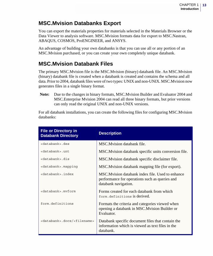
For all databank installations, you can create the following files for configuring MSC.Mvision databanks:
File or Directory in Databank Directory Description
<databank>.des MSC.Mvision databank file.
<databank>.unt MSC.Mvision databank specific units conversion file.
<databank>.dis MSC.Mvision databank specific disclaimer file.
<databank>.mapping MSC.Mvision databank mapping file (for export).
<databank>.index MSC.Mvision databank index file. Used to enhance performance for operations such as queries and databank navigation.
<databank>.mvform Forms created for each databank from which form.definitions is derived.
form.definitions Formats the criteria and categories viewed when opening a databank in MSC.Mvision Builder or Evaluator.
<databank>.docs/<filename> Databank specific document files that contain the information which is viewed as text files in the databank.
14
MSC.Mvision Builder uses many user-definable ASCII text files for system customization and operation. Most of the files stored in the databank directories are ASCII files which may be modified. The following section describes the above databank files.
The typical search path for auxiliary files is:
• Current directory
• Home directory
• Installation directory
Document Files
MSC.Mvision full-text attributes associates a file with an MSC.Mvision material record. Files can be viewed in MSC.Mvision and are referenced in the databank by the full or relative path, to include the file name. Text and image files are not part of the MSC.Mvision binary databank file, only the <path> and file name are stored in the databank.
The text files for MSC.Software-supplied databanks are stored in a subdirectory of the databank directory named <databank>.docs/. The files are divided into subdirectories and include the suffix .docs. The locations and names of these files are defined by the creator of the databank.
Because the text files are not part of the databank, they can be modified using a text editor1. To edit a specific text file, open the databank and select the material record. The Pedigree Window displays the path name of the text files available for that material. For example, MSC.Mvision using Databank Producers_metals.des, an Applications file for Cobalt MP159 manufactured by SPS indicates that the Applications Data is in the file:
producers_metals.docs/A01/A01292.doc
Navigate to that directory from the databank installation directory, then use a text editor to open and edit the file.
1This assumes that you have write permission to change the file.
15CHAPTER 1Introduction
Form Files
Form files customize the Criteria and Materials Sets for an individual databank. A databank can have an unlimited number of form files associated with it. Each form file can provide you with different viewing and searching options.
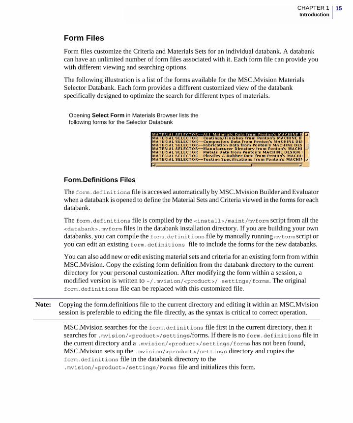
The following illustration is a list of the forms available for the MSC.Mvision Materials Selector Databank. Each form provides a different customized view of the databank specifically designed to optimize the search for different types of materials.
Form.Definitions Files
The form.definitions file is accessed automatically by MSC.Mvision Builder and Evaluator when a databank is opened to define the Material Sets and Criteria viewed in the forms for each databank.
The form.definitions file is compiled by the <install>/maint/mvform script from all the <databank>.mvform files in the databank installation directory. If you are building your own databanks, you can compile the form.definitions file by manually running mvform script or you can edit an existing form.definitions file to include the forms for the new databanks.
You can also add new or edit existing material sets and criteria for an existing form from within MSC.Mvision. Copy the existing form definition from the databank directory to the current directory for your personal customization. After modifying the form within a session, a modified version is written to ~/.mvision/<product>/ settings/forms. The original form.definitions file can be replaced with this customized file.
MSC.Mvision searches for the form.definitions file first in the current directory, then it searches for .mvision/<product>/settings/forms. If there is no form.definitions file in the current directory and a .mvision/<product>/settings/forms has not been found, MSC.Mvision sets up the .mvision/<product>/settings directory and copies the form.definitions file in the databank directory to the .mvision/<product>/settings/Forms file and initializes this form.
Opening Select Form in Materials Browser lists the following forms for the Selector Databank
Note: Copying the form.definitions file to the current directory and editing it within an MSC.Mvision session is preferable to editing the file directly, as the syntax is critical to correct operation.
16
Edits to Material Sets and Criteria made during an MSC.Mvision session, which are accessed by selecting Edit Menu from the Materials Browser, are recorded in the ~/.mvision/<product>/settings/Forms file regardless of the source of the form.definitions file.
• Resetting Form.definitions File
• To use a modified version of the form.definitions file which includes the edits, copy the modified file to form.definitions in the current startup directory and remove ~/.mvision/<product>/settings/Forms if it exists. To use the form.defintions file in the databank install directory, remove or rename the form.definitions file in the current directory and remove ~/.mvision/<product>/settings/Forms file.
• Saving Form.definitions File
• To save a modified version of the form.definitions file with specific edits created during an MSC.Mvision session, save a notebook. This will create the .mvision/<product>/notebook_dir_name/Form file. When MSC.Mvision is opened from that notebook, it will retrieve the modified form.definitions (forms) file.
• To capture a specific edited version of a form.definitions, exit MSC.Mvision at any point and move ~/.mvision/<product>/setting/Forms file to a file named form.definitions in the current directory and restart. MSC.Mvision always uses the form.defintions in the current directory and does not overwrite or edit the file.
• Editing Form.definitions File
• To manually edit the form.definitions file, open the file using a text editor. If you use this method, be very careful to maintain the correct formatting and syntax in the file.
• A customized form can only be renamed by manually editing the form.definitions file. All other editing can be performed interactively from within MSC.Mvision.
Disclaimer Files
MSC.Software-supplied databanks are created in partnership with the organization responsible for compiling or marketing the data. Therefore, a disclaimer appears documenting the limitations to the liability of the originators of the data and information creators of the databanks.
You can create a disclaimer file for any databank. The files are simple text files named using the convention <databank>.dis which are stored in the same directory as the databank files. A default disclaimer is located in the resources directory which is used if you do not create a disclaimer.
17CHAPTER 1Introduction
Units Conversion Files
Real (numeric) values in the MSC.Mvision databanks are stored in a units system determined by the creator of the databank. To allow you complete control over units conversion, MSC.Mvision uses an editable external file to control the conversion of values from one units system to another. These formatted text files are named according to the convention <databank>.unt and are stored in the directories with the databank files.
Index File
An index file can be generated for an MSC.Mvision databank. It contains formatted information about a databank’s organization that enables rapid access to data in the databank. MSC.Mvision uses the information contained in these files to accelerate access to the data in the databank when sorting and generating lists of data values. It is not necessary for a databank to have an index file.
Index files are binary files and can not be edited by the user. These files are created by MSC.Mvision Builder or a separate program available in the MSC.Mvision install directory.
Export Template and Mapping Files
The export function is a Remote Procedure Call (RPC), that allows the process to be completely self-contained and still interact with MSC.Mvision software. The export function is named Expfunc in the <install_dir>/export_functions directory.
The export function is controlled by two types of files:
<databank>.mapping
which is a databank specific file, and
<analysis_code>.template
which is an export code specific file.
Both file types are editable text files. The <databank>.mapping files are stored in the databank directory. The <analysis code>.template files are stored in the <install-dir>/resources directory. Export functions (executables) are stored in the <install-dir>export_functions directory.
Template Files - Template files define variable names used in both the mapping files and for passing data to the export function. Template files also define the structure of the export form in the user interface.
Mapping Files - Mapping files relate databank expressions to the variables defined in the export template and are databank specific. A databank expression is an algebraic expression which can include MSC.Mvision database programmatic interface (DPI) functions such as interpolation, maximum, minimum, and so on.
18
Session Files
A session file is automatically created as an output of each MSC.Mvision Builder session. It is a record of all building and spreadsheet commands which are executed during a session.
The session file is a text file created in the directory where MSC.Mvision Builder was initiated. The session file is named builder.ses.n where n is an integer incremented by one each time a build session is initiated in that directory.
In addition to providing a record of the build session used to create a databank, the session file provides a means of automating the building process. If a databank needs to be rebuilt, updated, or modified, you can accomplish this by replaying a session file. Playing a session file executes all the commands which are recorded in the file.
The spreadsheet also has the ability to replay session files. Session files replayed via the spreadsheet, ignores all non-spreadsheet commands. In conjunction with the session file, a log file is written to the current directory. This file is simply an information record of responses during the session.
Start Up Files
Four different functions within MSC.Mvision are used to define the start up state (conditions):
• Notebook Files
• Settings Files
• Spreadsheet Files
• Graphics Template Files
These files define the current display options, curve settings, databank settings, form edits, window sizes.
Several types of files are generated when an MSC.Mvision session is terminated. These files provide the flexibility required to optimize MSC.Mvision usage at a given site or to restart a new session where the previous session ended. MSC.Mvision uses these files to set the start up state of each MSC.Mvision session.
• Notebook Files
• After completion of any normally-terminated MSC.Mvision session, a ~/.mvision/<product>/notebook directory is created in the user’s home directory.
It contains several files which store the settings, databank specific items, window sizes, Materials Sets and Criteria, merged views, and so on. Notebooks are useful when you want to resume the current session or when you want to reinstate a previous session.
Note: The session file is an editable text file. You will probably want to edit it to remove unwanted commands or add commands or file names prior to replaying
19CHAPTER 1Introduction
• The Forms file is a copy of the form.definitions file as it existed when the session was saved.
• The Windows file contains the information required to configure the windows as they existed when saved.
• A notebook can also include spreadsheet files.
• The ~/.mvision/<product>/notebook is overwritten whenever MSC.Mvision is normally terminated and can be recalled with the last_notebook option. To permanently save a notebook, use Save Notebook prior to exiting.
• Settings Files
• Settings files are saved every time you quit an MSC.Mvision session. Settings files are similar to a notebook, but without the materials specific data. A notebook records everything about the previous session but the settings files store only the window configuration form settings, and so on. Settings are similar to a user’s preferences except they are recorded from session to session. A set of global settings can be placed in the MSC.Mvision installation directory to customize the start-up state for all users.
• At any time during an MSC.Mvision session or after termination of the session, you can save the settings which define the size of windows, options in the menus, merged view information, and any other non-databank specific options. The ~/.mvision/<product>/settings directory contains two files: Forms and Windows.
• The Forms file is a copy of the form.definitions file accessed during the last MSC.Mvision session. It is updated to include all edits performed interactively during the previous session.
• The Windows file contains a record of the all the settings for user-defined options at the time the settings were saved. These include merged views, display settings, print and export options, units conversion, directory and file names for selection, builder forms, and so on.
• Spreadsheet Files
• Spreadsheet files are a copy of the current spreadsheet in an MSC.Mvision formatted (binary) file to be used in subsequent sessions.
Spreadsheet files are created any time a spreadsheet is displayed and saved to any valid file name. The usual naming convention is <spreadsheet_name>.spd. These files can be opened from within MSC.Mvision using the spreadsheet Open command.
• If a spreadsheet is open when a notebook is saved or when exiting, a spreadsheet file of the currently displayed spreadsheet is saved in the notebook directory.
• Graphics Template Files
20
• MSC.Mvision can use templates to configure a view of a plot or curve if one has been created. A template is a formatted text file that stores the values for all of the options used to customize a view or curve. These files can be generated by the Template functions in the XY Graphics menu of the Data Viewer, the Cross Plot or the Spreadsheet Plot. These files allow the user to individually customize curves and plots.
• There are two types of template files, template_name.crv and template_name.plt. The .crv file contains the settings used to customize the view of a specified curve within a plot, such as, color, symbols, component visibility, and curve legend). More than one.crv file can be generated for plots that contain multiple curves. A .plt file contains all the settings required to represent the view of the plot title, legend formats and fonts, axis scaling, axis labels, tic formats and font, grid states, and so on.
• Template files are automatically written to a subdirectory of the user’s home directory named ~/.mvision/<product>/graphics. The template files located in the current directory, or the user’s home directory will also be read by the system. For global use, place the graphics template files in:<install-dir>/resources/<product>/graphics
• The system will access these files for all users. Template files can be deleted from within MSC.Mvision using the Delete option.
Additional Auxiliary Files
• .MIF Files
• Output to MIF from the Print window writes the formatted document to a <file_name>.mif file. MIF is the Maker Interchange Format language used by Framemaker, the document formatting program used in formatting the printed output. A .mif file can be directly incorporated into a Framemaker document.
21CHAPTER 1Introduction
• Postscript Files
• Output to Printer opens the preview window containing the formatted document. Selecting Print... from the File menu in the Preview window opens the Print window. The option Print Only to File creates a postscript print file in the specified directory. The name of the file is specified by the user. The usual naming convention is <file_name>.ps.
• Specified Postscript files can be printed by executing the UNIX print command.
• Application Resource Files
• When MSC.Mvision starts up, it searches for resource settings, such as, labels, fonts, color, window positions, and so on, in the standard X Window System application resource files. The resource settings for MSC.Mvision Builder are in a file named Mvbuild; for MSC.Mvision Evaluator the file is named Mveval, and for Framemaker the file is named Maker.
• The application resource file is a special file containing various settings used by MSC.Mvision. These settings control a wide variety of features, some of which you may want to change. Features such as foreground and background colors, window and menu labels, window variables and timing variables can be altered by editing the resource file. Each user can have a personal version of the application resource file to tailor MSC.Mvision to meet individual requirements.
• The X Windows System looks for resource files in several places. which can be used to customize the product for different purposes. Changes made to the global applications resource file in the install directory affect all users at the site. A resource file in the user’s home directory overrides global settings and allows the user to set personal requirements.
• MSC.Mvision searches for resource files to compile a resource database. Conflicting resource settings found in sequential files searched override those resources (line by line) found in the files searched previously. The last file read is used.
• External Functions
• External functions are special executable programs used with the spreadsheet and export. MSC.Mvision programs are supplied with external functions for both the spreadsheet and export. The Spreadsheet external functions are located in <install-dir>/ExFunc.
22
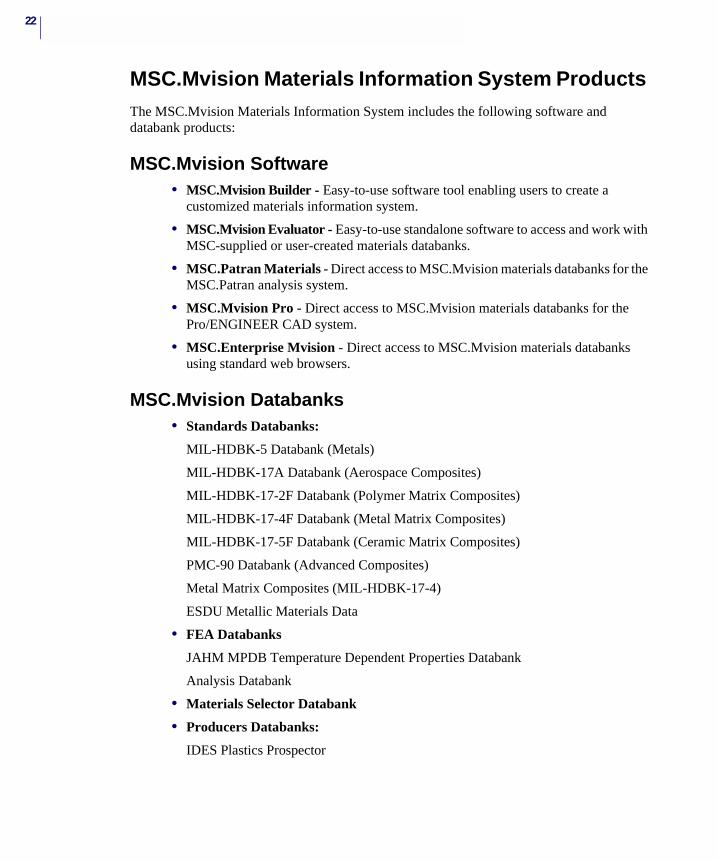
MSC.Mvision Materials Information System Products The MSC.Mvision Materials Information System includes the following software and databank products:
MSC.Mvision Software• MSC.Mvision Builder - Easy-to-use software tool enabling users to create a
customized materials information system.
• MSC.Mvision Evaluator - Easy-to-use standalone software to access and work with MSC-supplied or user-created materials databanks.
• MSC.Patran Materials - Direct access to MSC.Mvision materials databanks for the MSC.Patran analysis system.
• MSC.Mvision Pro - Direct access to MSC.Mvision materials databanks for the Pro/ENGINEER CAD system.
• MSC.Enterprise Mvision - Direct access to MSC.Mvision materials databanks using standard web browsers.
MSC.Mvision Databanks• Standards Databanks:
MIL-HDBK-5 Databank (Metals)
MIL-HDBK-17A Databank (Aerospace Composites)
MIL-HDBK-17-2F Databank (Polymer Matrix Composites)
MIL-HDBK-17-4F Databank (Metal Matrix Composites)
MIL-HDBK-17-5F Databank (Ceramic Matrix Composites)
PMC-90 Databank (Advanced Composites)
Metal Matrix Composites (MIL-HDBK-17-4)
ESDU Metallic Materials Data
• FEA Databanks
JAHM MPDB Temperature Dependent Properties Databank
Analysis Databank
• Materials Selector Databank
• Producers Databanks:
IDES Plastics Prospector
23CHAPTER 1Introduction
• Reference Databanks:
Penton’s Materials Selector
PDL Chemical Compatibility of Plastics
PDL Effect of Temperature on Plastics
PDL Effect of Creep on Plastics
ASM Alloy Steel Databank
ASM Aluminum Databank
ASM Composites Databank
ASM Copper Databank
ASM Corrosion Databank
ASM Magnesium Databank
ASM Nylons Databank
ASM Stainless Steels Databank
ASM Structural Steels Databank
ASM Thermoplastics Databank
ASM Thermoset Plastics Databank
ASM Titanium Databank
• Cross Reference Databanks:
ASM Alloy Finder
ASM Woldman’s Engineering Alloys
ASM Worldwide Guide to Equivalent Irons & Steels
ASM Worldwide Guide to Nonferrous Metals & Alloys
• GE Plastics Databank
• Special Purpose Databank:
Fatigue
Fibers
Thermal
Electromagnetic Materials
Dytran
• Demo Tutorial Databanks:
Demo_Composites
Demo_Metals
24
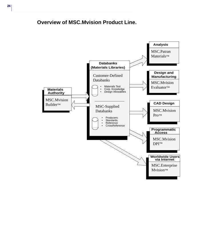
Overview of MSC.Mvision Product Line.
MSC.Mvision Builder™
MaterialsAuthority
• Materials Test• Corp. Knowledge• Design Allowables
• Producers• Standards• Reference• CrossReference
Databanks
MSC-Supplied Databanks
Customer-DefinedDatabanks
(Materials Libraries)
MSC.PatranMaterials™
MSC.MvisionEvaluator™
Analysis
Design andManufacturing
ProgrammaticAccess
MSC.MvisionDPI™
ProgrammaticAccess
MSC.Mvision
DPI™
Worldwide Usersvia Internet
MSC.Enterprise Mvision™
CAD Design
MSC.Mvision Pro™

25CHAPTER 1Introduction
Technical SupportFor help with installing or using an MSC.Software product, contact your local technical support services. Our technical support provides the following services:
• Resolution of installation problems
• Advice on specific analysis capabilities
• Advice on modeling techniques
• Resolution of specific analysis problems (e.g., fatal messages)
• Verification of code error.
If you have concerns about an analysis, we suggest that you contact us at an early stage.
You can reach technical support services on the web, by telephone, or e-mail:
Web Go to the MSC.Software website at www.mscsoftware.com, and click on Support. Here, you can find a wide variety of support resources including application examples, technical application notes, available training courses, and documentation updates at the MSC.Software Training, Technical Support, and Documentation web page.
Phone and Fax
Email Send a detailed description of the problem to [email protected].
United StatesTelephone: (800) 328-4672Fax: (714) 784-4056
Frimley, CamberleySurrey, United KingdomTelephone: +(44) (1276) 60 19 00Fax: +(44) (1276) 60 19 09
Munich, GermanyTelephone: +(49) (89) 431 987 0Fax: +(49) (89) 436 17 16
Tokyo, JapanTelephone: (81) (3) 6911 1200Fax: (81) (3) 6911 1201
Rome, ItalyTelephone: +(39) (06) 52 79 931Fax: +(39) (06) 52 27 32 32
Paris, FranceTelephone: (33) (1) 69 36 69 36Fax: (33) (1) 69 36 45 17
Moscow, RussiaTelephone: +(7) (095) 363 06 83Fax: +(7) (095) 787 76 06
Gouda, The NetherlandsTelephone: +(31) (182) 536 444Fax: +(31) (182) 538 418
Madrid, SpainTelephone: +(34) (91) 5560 919Fax: +(34) (91) 5567 280

26
MSC.Mvision Builder and Evaluator 2002 Installation Guide
2 Planning Databanks
� Overview
� Building Databanks Process
� Building Databanks Checklist
� Organizing the Project
� Accessing MSC.Mvision Builder
� Disk Space Management
28
OverviewConstructing a databank that is easy to understand and work with and effectively meets the needs of its various users can be accomplished with careful planning.
This section provides the information required to successfully plan and design an MSC.Mvision databank to meet the requirements of your organization and the needs of the users of the data.
Using Databank StandardsObtaining consensus on technical standards is a difficult process. This is particularly true in the complex area of material properties where many different forms of representation have become firmly established over the years in various parts of the industries.
Occasionally, there are specific and valid reasons for not conforming to an established standard. For example, if a standard name is specified for a property such as elastic modulus, values from different materials should not be blindly lumped together under that name if they were obtained by different test methods or in different environments, or if they vary for some reason. There are usually ways to make these distinctions clear. This represents one of the difficulties to be resolved in just one facet of materials data management.
Recognizing that different users have their own views about data representation, units, and so on. MSC.Mvision provides a wide range of flexibility and recommends and supports evolving standards. Users are allowed to make their own decisions regarding specific formats and conventions. The goal of MSC.Mvision is to provide a central and consistent means of accessing data from various forms, sources, and formats.
The standards community has devoted much effort to the subject of electronic materials databases. In particular, the ASTM Committee E49 on Computerization of Material Properties Data has published a number of manuals, technical publications and proceedings from conferences and seminars. If your data are likely to be shared beyond a small group of users, you could probably benefit from the concepts developed by E49, ISO (International Standards Organization), and other groups such as Military Handbooks 5 and 17 in the U.S. A good place to start is with ASTM PCN 28-019093-63, Manual on The Building of Materials Databases, Crystal H. Newton, ed.
MSC.Mvision continues to be involved in the activities of these and other standards groups. MSC.Mvision offers databanks that conform to the standards of these groups and includes data from published sources.
29CHAPTER 2Planning Databanks
Building Databanks ProcessMSC.Mvision is a very flexible system that permits many different ways of building and organizing data objects. There are numerous logical ways to organize a databank. Some ways may be better than others depending on the situation, but the key to decision making is to determine the context of the databank usage.
A databank may be supporting different user profiles and there may be many different ways to represent the data. Often there are subtle relationships between various parts of the data structure and important details that should be clearly represented in the databank. Most data has many small but important differences. A databank can be very simple or very complex depending on the amount and variety of data and user requirements. A thorough understanding of the problem and user profiles will help you create a usable databank.
The following list is a general outline of the Building Databanks Process, and a brief description of what is included in that part of the process for building databanks:
1. Plan Databanks - Organize the project including defining the user profile and designing the project.
2. Design Databanks - Name the databank, define attributes and relations and the hierarchical structure, and identify relation names and their relationships.
3. Create Databanks - Initialize databanks, construct data input files, load data into databanks, create prototypes, and save the databank.
4. Revise Schemas and Databanks - Review, revise, and reload schemas and databanks.
5. Create Customization Files - Add optional files to customize databanks and interface.
The next section contains the Building Databanks Checklist, which is a general outline of the steps required to create an MSC.Mvision databank.
When planning a new databank you need to know your user’s requirements for the databank, and how to structure your databank depending on its intended use.
An MSC.Mvision databank uses a special structure designed for presenting materials information. This architecture is referred to as the databank schema. The schema is composed of data items named attributes, which are organized into groups called relations. Relations are arranged in order to form a hierarchy.
The remainder of this manual includes the details of databank building. Topics are generally presented in the order encountered during construction of a databank. You will learn by building simple databanks that have the features you’ll want to include in a full scale databank. Refer to online help or the online manual accessed using the Help buttons in the various windows of the Builder application for assistance.
A databank refers to an electronic database of information built and accessed with MSC.Mvision software. MSC.Mvision was originally designed for material properties and metadata (supporting or qualifying data). Although this document focuses on that application, there is nothing in the software that limits it specifically to materials information.

30
MSC.Mvision databanks have been built for a number of topics and purposes such as reference libraries and parts databanks, and so on. The system is increasingly being used to address the larger area of Product Data Management (PDM).
The value of a completed databank is measured by how easily users can find and use the data they are seeking. Organization is the single most important factor in making a databank easy to use. For MSC.Mvision databanks, the best results are achieved by carefully thinking through the design of the databank schema (structure) used to organize the databank. If you have experience with data modeling design techniques, such as Object Oriented Design, you will find that you can build your conceptual data model according to those principles and then implement it using an MSC.Mvision schema. Accordingly, this manual emphasizes the basic principles involved in defining good databank schemas.
To get a quick idea of how databank building works, try the tutorial example in Appendix A.
Note: To build, write to, or modify MSC.Mvision databanks, you must have a license for the MSC.Mvision Builder software. You can use parts of or modify any of the commercial product databanks licensed from MSC, but the modified versions remain tagged and you need a databank license to open them.
31CHAPTER 2Planning Databanks
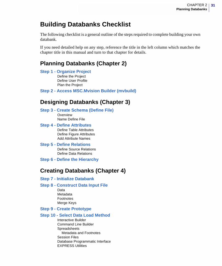
Building Databanks ChecklistThe following checklist is a general outline of the steps required to complete building your own databank.
If you need detailed help on any step, reference the title in the left column which matches the chapter title in this manual and turn to that chapter for details.
Planning Databanks (Chapter 2)Step 1 - Organize Project
Define the ProjectDefine User ProfilePlan the Project
Step 2 - Access MSC.Mvision Builder (mvbuild)
Designing Databanks (Chapter 3)Step 3 - Create Schema (Define File)
OverviewName Define File
Step 4 - Define AttributesDefine Table AttributesDefine Figure AttributesAdd Attribute Names
Step 5 - Define RelationsDefine Source RelationsDefine Data Relations
Step 6 - Define the Hierarchy
Creating Databanks (Chapter 4)Step 7 - Initialize Databank
Step 8 - Construct Data Input FileDataMetadataFootnotesMerge Keys
Step 9 - Create Prototype
Step 10 - Select Data Load MethodInteractive BuilderCommand Line BuilderSpreadsheets
Metadata and FootnotesSession FilesDatabase Programmatic InterfaceEXPRESS Utilities
32
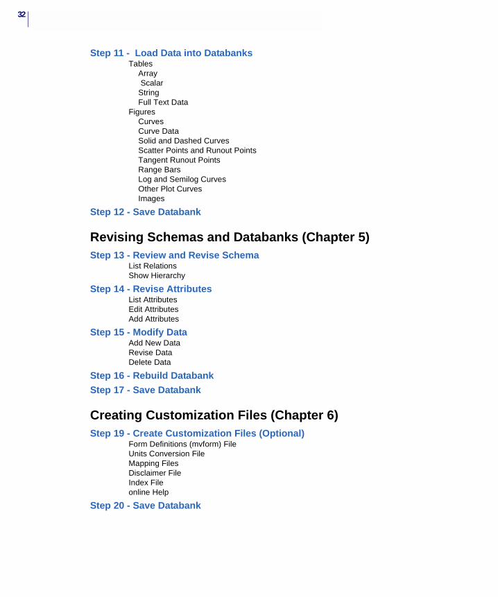
Step 11 - Load Data into DatabanksTables
Array ScalarStringFull Text Data
Figures CurvesCurve Data Solid and Dashed CurvesScatter Points and Runout PointsTangent Runout PointsRange BarsLog and Semilog CurvesOther Plot CurvesImages
Step 12 - Save Databank
Revising Schemas and Databanks (Chapter 5)Step 13 - Review and Revise Schema
List RelationsShow Hierarchy
Step 14 - Revise AttributesList AttributesEdit AttributesAdd Attributes
Step 15 - Modify DataAdd New DataRevise DataDelete Data
Step 16 - Rebuild Databank
Step 17 - Save Databank
Creating Customization Files (Chapter 6)Step 19 - Create Customization Files (Optional)
Form Definitions (mvform) FileUnits Conversion FileMapping Files Disclaimer FileIndex Fileonline Help
Step 20 - Save Databank

33CHAPTER 2Planning Databanks
Organizing the ProjectWhen designing your databank project, consider that this databank may not only be for organizing and storing data, but also for accessing data. First, examine the entire project by getting an overall idea of what the users want and what they want to accomplish, then decide on the composition of the databank.
Getting StartedAsking yourself the following questions can help you identify the major components of the project:
1. Who are the potential users or user groups?
2. What are the user’s or user group’s requirements?
3. What are the data sources?
4. Is the data already computerized?
5. What resources are available?
6. What data has already been gathered that you can use or learn from?
7. What approaches might help design and build a successful databank?
You might want to study the structure of existing databanks. You can do this by gathering all the data before starting to create a databank. Then, open and use the existing or similar databanks in the same way you anticipate working with the databank you are designing. Observe which features work best, which do not work very well, and then decide what features you will incorporate when developing your databank.
One of the best approaches to designing databanks is Using Object-Oriented Design Techniques. You do not have to be an expert in this field to apply some of the basic principles toward your design. The underlying philosophy is to carefully define the problem, identify the objects that make up the system (in this case the data objects you will be loading in the databank), then assemble these objects into a data structure based on their relationship to each other.
If you would like to learn more about this technology, an excellent reference is Object-Oriented Modeling and Design, James Rumbaugh et. al., Prentice-Hall, 1991.
Defining the ProjectTo help you define the project, it’s important to first describe the purpose of the databank, its intended content and scope. Whether the project you are undertaking is large or small, you risk producing an unsatisfactory product by starting out with a vague idea of the project and what constitutes an acceptable solution.
Asking yourself the following questions can help you define the content and scope:
1. Will the data come from more than one source or in more than one format?
34
2. Is the information current?
3. Is there platform compatibility problems for source collection, translation, databank building, and so on?
4. What are the standards requirements?
5. What are the units requirements?
6. How often will the databank be updated and how?
7. Who has the rights to the data, its distribution and use?
8. Will part of the data be restricted to specific users?
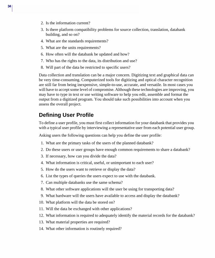
Data collection and translation can be a major concern. Digitizing text and graphical data can be very time-consuming. Computerized tools for digitizing and optical character recognition are still far from being inexpensive, simple-to-use, accurate, and versatile. In most cases you will have to accept some level of compromise. Although these technologies are improving, you may have to type in text or use writing software to help you edit, assemble and format the output from a digitized program. You should take such possibilities into account when you assess the overall project.
Defining User ProfileTo define a user profile, you must first collect information for your databank that provides you with a typical user profile by interviewing a representative user from each potential user group.
Asking users the following questions can help you define the user profile:
1. What are the primary tasks of the users of the planned databank?
2. Do these users or user groups have enough common requirements to share a databank?
3. If necessary, how can you divide the data?
4. What information is critical, useful, or unimportant to each user?
5. How do the users want to retrieve or display the data?
6. List the types of queries the users expect to use with the databank.
7. Can multiple databanks use the same schema?
8. What other software applications will the user be using for transporting data?
9. What hardware will the users have available to access and display the databank?
10. What platform will the data be stored on?
11. Will the data be exchanged with other applications?
12. What information is required to adequately identify the material records for the databank?
13. What material properties are required?
14. What other information is routinely required?
35CHAPTER 2Planning Databanks
Keep in mind that you may have one user, multiple users, or user groups to satisfy with the new databank. You need to decide if you are going to build only one databank to satisfy all your users or if you are going to build more than one databank. Remember that keeping all the data together in one databank makes updating a lot simpler and more accurate. Smaller databanks can be created easily from a larger master databank.
There are also software system requirements to consider: you might also want to verify that the users have a current MSC.Mvision license for the chosen platform. If a network is required, you might want to verify availability to the network.
Planning the ProjectUsing the information gathered in the previous questions, you now need to identify all the data objects and define their relationships. Object-oriented design tools are useful for this task, but you can do the same on paper or by using a word processing application.
To identify all the data objects and define their relationships, do the following:
1. List all the data objects that pertain to the subject. Be sure to include even those items that don’t seem to be particularly important.
2. Build a data dictionary by writing definitions and descriptions for each of the data objects.
3. Group the data objects that are closely related.
The data objects you identify become the attributes and relations in the MSC.Mvision databank schema.
When writing the descriptions of the data objects, you can make them as brief or as long as you like. Think of each object and its relationship to the overall collection of objects. It will also help you identify the relationships and hierarchy that determines the databank schema.
36
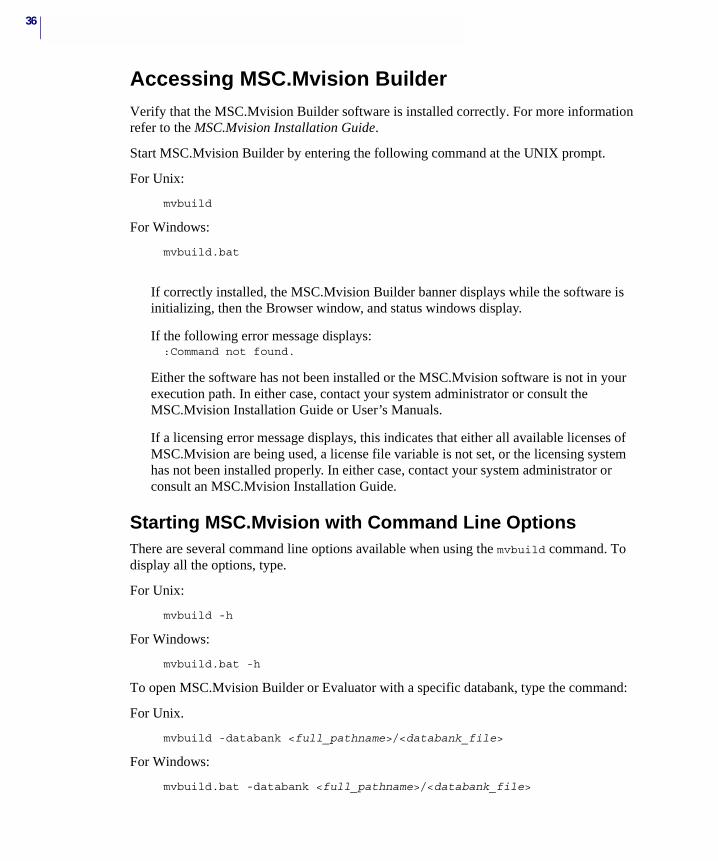
Accessing MSC.Mvision BuilderVerify that the MSC.Mvision Builder software is installed correctly. For more information refer to the MSC.Mvision Installation Guide.
Start MSC.Mvision Builder by entering the following command at the UNIX prompt.
For Unix:
mvbuild
For Windows:
mvbuild.bat
If correctly installed, the MSC.Mvision Builder banner displays while the software is initializing, then the Browser window, and status windows display.
If the following error message displays::Command not found.
Either the software has not been installed or the MSC.Mvision software is not in your execution path. In either case, contact your system administrator or consult the MSC.Mvision Installation Guide or User’s Manuals.
If a licensing error message displays, this indicates that either all available licenses of MSC.Mvision are being used, a license file variable is not set, or the licensing system has not been installed properly. In either case, contact your system administrator or consult an MSC.Mvision Installation Guide.
Starting MSC.Mvision with Command Line OptionsThere are several command line options available when using the mvbuild command. To display all the options, type.
For Unix:
mvbuild -h
For Windows:
mvbuild.bat -h
To open MSC.Mvision Builder or Evaluator with a specific databank, type the command:
For Unix.
mvbuild -databank <full_pathname>/<databank_file>
For Windows:
mvbuild.bat -databank <full_pathname>/<databank_file>
37CHAPTER 2Planning Databanks
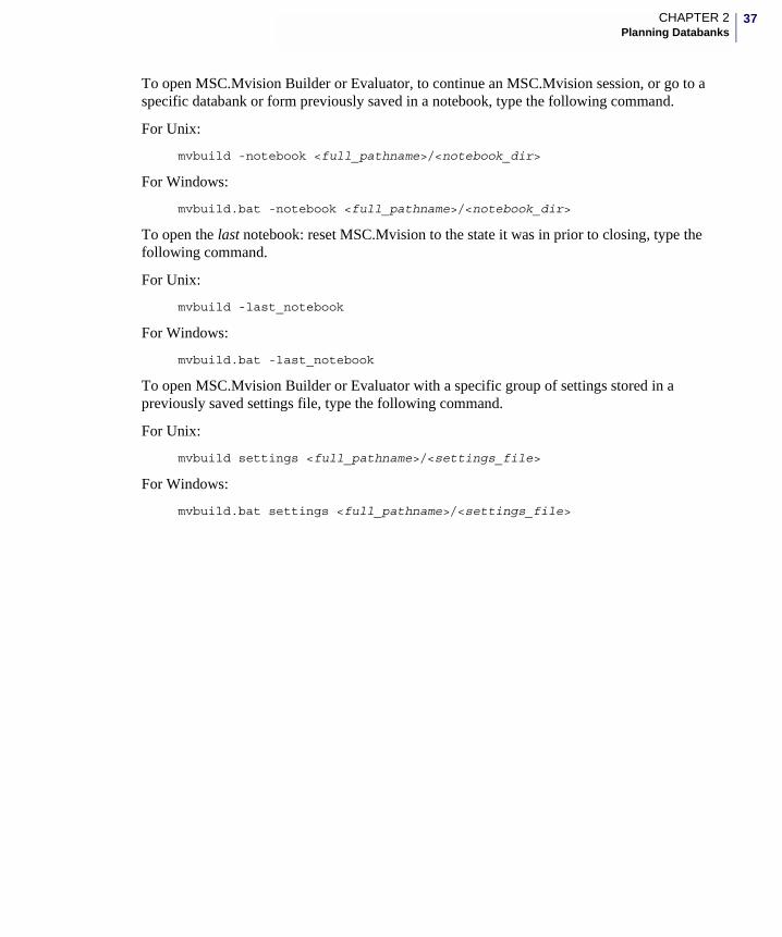
To open MSC.Mvision Builder or Evaluator, to continue an MSC.Mvision session, or go to a specific databank or form previously saved in a notebook, type the following command.
For Unix:
mvbuild -notebook <full_pathname>/<notebook_dir>
For Windows:
mvbuild.bat -notebook <full_pathname>/<notebook_dir>
To open the last notebook: reset MSC.Mvision to the state it was in prior to closing, type the following command.
For Unix:
mvbuild -last_notebook
For Windows:
mvbuild.bat -last_notebook
To open MSC.Mvision Builder or Evaluator with a specific group of settings stored in a previously saved settings file, type the following command.
For Unix:
mvbuild settings <full_pathname>/<settings_file>
For Windows:
mvbuild.bat settings <full_pathname>/<settings_file>

38
Disk Space ManagementMSC.Mvision creates a temporary file on disk to hold the databank as it is being built. The location of the temporary file is in the directory where the command to run the MSC.Mvision Builder was issued. You can change the location of the temporary file by setting an environment variable named MV_TMPDIR.
For example, to set the temporary file to be written to the /tmp directory, use one of the following two commands before starting MSC.Mvision Builder:
setenv MV_TMPDIR /tmp - C Shell
MV_TMPDIR=/tmp;export - Borne or Korn Shell
Note: You may want to consider breaking a large input file into smaller parts. This permits you to save intermediate versions of the databank via the File - Builder Functions - Save Databank menu option. This can be very useful if an error occurs in loading the data.
MSC.Mvision Builder and Evaluator 2002 Installation Guide
3 Designing Databanks
� Overview
� Understanding MSC.Mvision Terms
� Creating Schemas (Define Files)
� Defining Attributes
� Defining Relations
� Defining the Hierarchy
� MSC.Mvision Unique Identifier

40
OverviewThe MSC.Mvision databank structure is a hybrid of relational and hierarchical system.
Essentially, a MSC.Mvision databank is a structured series of tables (relations), which contain rows of attributes which in turn can be assigned values. These tables are organized in parent/child relationships in which a parent can have one or many children, but a child can only have one parent.
A MSC.Mvision databank requires a hierarchy that defines a series of tables at the top of the databank that in turn defines a path to the property set tables or data relations. The hierarchy tables are an ordered set of tables; each table a parent of the next lower table. The property set tables are children of the lowest level hierarchy table. Property set tables do not have children. The individual list or row of attributes for each table composes a table row within a table. A table row can be a parent of a table row in the next lower level table or a child of a table row in the next higher table.
Using this databank structure a “material” is defined as a series of table rows connected together to define the path through the databank and provides all the attribute values associated with a unique “material”.
MSC.Mvision provides access to each element of the databank structure to include tables, attributes, footnotes, metadata, and so on. As of Version 2002, the MSC.Mvision databank contains a UID (Global Unique Identifier) for every table row within the databank. This UID is a special property of each table row within the databank and is automatically created upon creation of the databank.
The design of the databank structure schema can make a significant difference in easily finding and using information. The database structure also affects data entry, data loading, storage efficiency, and ease of maintenance.
The primary instrument for designing an MSC.Mvision databank is the schema or define file, which describes the data structure. This chapter provides information and describes the steps for designing schemas by organizing and naming the attributes, relations and hierarchy.
If this is the first time you are designing a databank, expect to repeat the building and testing process several times before attempting to load large amounts of data into your new databank. You do not want to load large amounts of data into a databank that is either not complete or incorrect.
41CHAPTER 3Designing Databanks
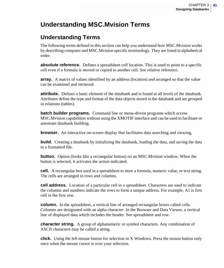
Understanding MSC.Mvision Terms
Understanding TermsThe following terms defined in this section can help you understand how MSC.Mvision works by describing computer and MSC.Mvision specific terminology. They are listed in alphabetical order.
absolute reference. Defines a spreadsheet cell location. This is used to point to a specific cell even if a formula is moved or copied to another cell. See relative reference.
array. A matrix of values identified by an address (location) and arranged so that the value can be examined and retrieved.
attribute. Defines a basic element of the databank and is found at all levels of the databank. Attributes define the type and format of the data objects stored in the databank and are grouped in relations (tables).
batch builder programs. Command line or menu-driven programs which access MSC.Mvision capabilities without using the XMOTIF interface and can be used to facilitate or automate databank building.
browser. An interactive on-screen display that facilitates data searching and viewing.
build. Creating a databank by initializing the databank, loading the data, and saving the data to a formatted file.
button. Option (looks like a rectangular button) on an MSC.Mvision window. When the button is selected, it activates the action indicated.
cell. A rectangular box used in a spreadsheet to store a formula, numeric value, or text string. The cells are arranged in rows and columns.
cell address. Location of a particular cell in a spreadsheet. Characters are used to indicate the columns and numbers indicate the rows to form a unique address. For example, A1 is first cell in the first row.
column. In the spreadsheet, a vertical line of arranged rectangular boxes called cells. Columns are designated with an alpha character. In the Browser and Data Viewer, a vertical line of displayed data which includes the header. See spreadsheet and row.
character string. A group of alphanumeric or symbol characters. Any combination of ASCII characters may be called a string.
click. Using the left mouse button for selection in X Windows. Press the mouse button only once when the mouse cursor is over your selection.
42
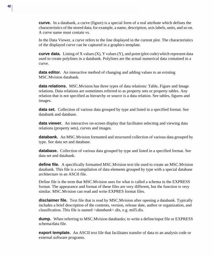
curve. In a databank, a curve (figure) is a special form of a real attribute which defines the characteristics of the stored data; for example, a name, description, axis labels, units, and so on. A curve name must contain vs.
In the Data Viewer, a curve refers to the line displayed in the current plot. The characteristics of the displayed curve can be captured in a graphics template.
curve data. Listing of X values (X), Y values (Y), and point (plot code) which represent data used to create polylines in a databank. Polylines are the actual numerical data contained in a curve.
data editor. An interactive method of changing and adding values to an existing MSC.Mvision databank.
data relations. MSC.Mvision has three types of data relations: Table, Figure and Image relations. Data relations are sometimes referred to as property sets or property tables. Any relation that is not specified as hierarchy or source is a data relation. See tables, figures and images.
data set. Collection of various data grouped by type and listed in a specified format. See databank and database.
data viewer. An interactive on-screen display that facilitates selecting and viewing data relations (property sets), curves and images.
databank. An MSC.Mvision formatted and structured collection of various data grouped by type. See data set and database.
database. Collection of various data grouped by type and listed in a specified format. See data set and databank.
define file. A specifically formatted MSC.Mvision text tile used to create an MSC.Mvision databank. This file is a compilation of data elements grouped by type with a special database architecture in an ASCII file.
Define file is the term that MSC.Mvision uses for what is called a schema in the EXPRESS format. The appearance and format of these files are very different, but the function is very similar. MSC.Mvision can read and write EXPRES format files.
disclaimer file. Text file that is read by MSC.Mvision after opening a databank. Typically includes a brief description of the contents, version, release date, author or organization, and classification. This file is named <databank>.dis, e.g. mil5.dis.
dump. When referring to MSC.Mvision databanks; to write a define/input file or EXPRESS schema/data file.
export template. An ASCII text file that facilitates transfer of data to an analysis code or external software programs.
43CHAPTER 3Designing Databanks
EXPRESS Translators. MSC.Mvision utility programs provided to convert or translate MSC.Mvision databanks to or from ASCII text files in EXPRESS schema and data file format.
figure. A graphical object. An MSC.Mvision figure can contain either a curve or an image. Graphical objects are accessed and displayed via the Browser, Data Viewer, or Spreadsheet.
figure relations. In an MSC.Mvision databank, this is a type of data relation (property set) which consists of a curve or image attribute definition.
footnote. Auxiliary information about an entry within a databank. MSC.Mvision footnotes facilitate attachment of a comment to individual entries in a databank. Footnotes can be displayed in the pedigree or Data Viewer and in braces to the right of the data value. Footnotes can also be queried and displayed in the Browser or Spreadsheet.
form.definitions file. A formatted text file that is read by the MSC.Mvision system to configure the display of a databank in the Materials Browser window.
full text attribute. A special type of character attribute that contains a file name of an external file. The external file can be any valid file which is usually a text or image file.
help. Provides information about the software you are currently using. Help is available using either the online manual or online help information.
helper. An MSC.Mvision feature that allows the user to issue system commands that include file names contained in full text attributes. Command definitions, and associations are stored in the /.mvision/helpers file.
hierarchy. Directive in a define file that establishes the basic structure of the databank and the sequence of the relationships between groups of attributes within the databank.
hierarchy relation. In an MSC.Mvision databank, a table defined in the hierarchy.
image. A special type of integer attribute that associates and accesses specific format image files for display via the MSC.Mvision Image Browser. Image is a type of figure.
image relations. A type of data relation (property set) consisting of a single image attribute definition.
index file. An MSC.Mvision binary file which can be created to enhance query and display speed for a specific databank. This file is an optional file. Index files must be named: databank.index.
input file. An MSC.Mvision formatted text file which details data structure and values with proper syntax to organize data to be compiled (loaded) in an MSC.Mvision databank. The data structure in an input file must match the databank to which it is applied. This structure is established by the define file and the naming convention is databank.inp.
44
instance. In the MSC.Mvision build process and spreadsheet, the current value of an attribute is referred to as an instance.
load. To add data to a databank. The most common method is to use an MSC.Mvision input file via the interactive Browser or batch programs. There are four different methods used to add data to an MSC.Mvision databank:
• Input Files
• Database Programmatic Interface (DPI)
• Spreadsheet
• EXPRESS Files
mapping files. Formatted text files that define mapping of the attribute names in the databank to the entities defined in the export template. Mapping files must be named: databank.mapping.
material. A product consisting of matter; the elements or substance or parts for manufacturing other products. For example a type of material in a general metals class could be steel or aluminum. Within an MSC.Mvision databank, a material is the complete path (series of table rows) that defines a unique material.
material properties. Qualities or traits that are able to be measured by specifically defined procedures which are common to all members of a specific class of materials.
Materials Browser . The main MSC.Mvision window used to open databanks, examine lists of materials, search for specific materials, select materials to view, or output property data.
menu bar. The area, usually a narrow rectangle across the top of a window which lists the menu options. These menu options may have pulldown menus which are displayed when the option is selected.
menu option. The items displayed in the menu bar and on the pulldown and popup menus and other various menus. Selecting an option usually performs an action.
menu title. Usually the first line across the top of a window which lists the title of the current menu.
merge keys. MSC.Mvision specified keywords which are attached to relation names in an input file. These keys activate functions which give you explicit control over matching and adding data when loading in a databank.
metadata. A superset of text data which applies to every attribute of a specific type within the databank or a portion of the databank. Metadata is specified after loading data and is only applied to real attributes.
Motif window. Interactive computer window configured in the X Window System environment. All windows in MSC.Mvision are Motif format.
45CHAPTER 3Designing Databanks
mouse button. Any of the buttons on a mouse used to indicate a position on the screen or select menus or options. When using MSC.Mvision (and the mouse is set for a right-handed user), the left mouse button is used to indicate a screen position and normal selection. The right mouse button is used to activate popup menus.
MSC.Mvision Databank. An electronic database in MSC.Mvision format with defined structure and content. The database is stored as a binary file.
online manual. MSC.Mvision has incorporated this manual and separate help information into the software that is available on your workstation using the HELP menu option from the menu bar and as an option on the MSC.Mvision window.
online help. MSC.Mvision has incorporated this manual into the software that is available on your workstation. It can be accessed by selecting the HELP button on forms.
pane. Window within a window. Panes can be resized using the sash separator located between panes. Also called a frame.
path. Hierarchical file systems include directories and files. Directories contain files and subdirectories. A path name is made up of the directory names needed to locate a file starting from the top of the hierarchy. Within an MSC.Mvision databank a path is a connected series of table rows.
pedigree. Information needed to precisely identify the material for which data is displayed or to qualify the displayed data.
plot. Figure or combination of figures displayed. The characteristics of a plot can be captured in a .plt graphics template. Plots can be created from the Data Viewer, Cross Plot or Spreadsheet.
polyline. A formatted numerical array that represents the XY coordinates and plot code of a continuous or noncontinuous line. Polylines can be created in a spreadsheet or loaded in a figure in a databank using input files.
popup menu. Menu which is accessed by pressing the right mouse button. This menu contains options which are also available from pulldown menus. Popup menus are available in the Materials Browser, Data Viewer, Spreadsheet, and XY Graphics Plot windows.
properties. Traits belonging to a material. For example, data for aluminum might include temper properties such as: temperature when heat-treated, time at that temperature, and cooling temperature controls as well as measured or calculated values. The values of attributes within data relations are also referred to as properties
property tables. Data relations (property sets) containing scalar or character attributes, or attributes other than curves or images. These tables are displayed in the Data Viewer. In an MSC.Mvision databank a property table is any table that is not a hierarchy or source table.
46
pulldown menu. Menu which is accessed by selecting an option from the menu bar and pressing the left mouse button. The pulldown menu displays further menu options for the selected option.
radio button. Special button to the left of an option on a menu. If the button is red, the option is activated. Select the option to toggle. A radio button and its option can be toggled interactively by previous menu option choices.
relation. A grouping of attributes. Synonymous with table.
relation name. Name for a group of attributes. This name is specified in a load file and is displayed in the attribute list. Synonymous with table name.
relative reference. Within the MSC.Mvision spreadsheet, this defines a cell location in relation to the current location of a formula. If the formula is moved or copied, the relationships maintained. For example, if a cell points to a cell directly above, it will still point to the cell directly above when moved. See absolute reference.
row. In an MSC.Mvision spreadsheet display, a horizontal line of arranged rectangular boxes called cells used in a spreadsheet. See column and spreadsheet. In a Browser, a horizontal line of displayed data. In an MSC.Mvision databank, a line of data which can be queried as row_id. Synonymous with table row (this is a grouping of attribute values within a table).
scalar. A single (real or integer) numeric value.
schema. A formatted compilation of definitions of data objects referred to as attributes which are organized in tables. Adefine file (MSC.Mvision-specific format), or a schema file (EXPRESS format) determines the schema.
The databank structure (hierarchy, property sets, source) is sometimes referred to as the databank schema.
scroll. Move up or down horizontally or left and right vertically usually using scroll bars. For example, scrolling up or down within a list of file names.
select. Chose (click) an option or item from a list, an option from a menu, or a button from a window. Select is also a specific function in the MSC.Mvision spreadsheet that extracts data from a databank.
session file playback. The capability of re-executing a previously recorded session. This can be used to automate databank construction and loading.
source. Data that can be universally or individually attached to material entries to identify or qualify data.
47CHAPTER 3Designing Databanks
source relation. In an MSC.Mvision databank, a special relation that is shared and can be seen by all data relations (property sets) which share the same hierarchy relations. All MSC.Mvision databanks must have a source relation. The source relation is always the last relation specified in the hierarchy definition. Also called source table.
spreadsheet. A computerized version of a ledger sheet like those used by accountants. This ledger has small rectangular boxes called cells which are arranged horizontally in rows and vertically in columns. A spreadsheet can contain numbers, formulas or text strings. The MSC.Mvision spreadsheet has many built-in functions for accessing and manipulating data. See column and row.
string. Any combination of ASCII characters that may include numbers and symbols. Also called text string.
tear-off menu. A special type of pulldown menu indicated by a horizontal dashed line across the top. Select the dashed line to move this pulldown menu anywhere in the window for easy access and frequent use.
toggle. Menu options which can change state according to menu option choices. For example, if you select YES on a menu it changes to NO and vice versa. Both option choices are not displayed simultaneously.
tools. MSC.Mvision options accessed from the Materials Browser and Data Viewer windows. These tools include the spreadsheet, query wizard and helpers.
units conversion file. File containing databank specific mappings for named alternate units conversion sets. This file provides conversion factors used by the software to convert real attribute values to a named alternate units systems. File must be named databank.unt.
uid. In an MSC.Mvision databank, each table (relation) row contains a unique identifier which consists of three elements: the table name, a namespace and a unique row id. A query for a uid will provide access to a unique ‘material’ by attaching a unique table row with the associated parent and child table rows.
windows. Areas on a terminal screen that are displayed window-like in form and usually include a Window Title, Menu Bar, buttons and a work space.
48
Creating Schemas (Define Files)MSC.Mvision is a very flexible system that permits many ways of creating a structure for data objects. There are numerous logical ways to organize a databank, although some are better than others. The key to these decisions is in the databank usage. For example, if the user will primarily be browsing through the hierarchy of data, then the hierarchy design is critical. If the user will primarily be using the databank for structured queries, it is less important.
Databank usage is where consideration of the user profiles and project definition from the previous chapter can help provide you with the information and direction needed for creating an effective databank.
The hierarchy of a databank cannot be interactively modified. After it is established by the define file, the hierarchy is set unless the databank is rebuilt. To change the databank hierarchy, you must change the define file and rebuild the databank.
The following list gives you a general idea of the steps needed to create a define file. These steps are detailed in this chapter in the same order used to create a define file.
• Create and Name Schemas (Define Files)
• Define and Name Attributes
• Define and Name Relations
• Define and Name Hierarchy
GuidelinesMSC.Mvision databanks use a basic structure designed for presenting materials information. This architecture is referred to as the databank schema. The schema is composed of data items referred to as attributes, which are organized into groups called relations. Relations are arranged in a logical order to form a hierarchy.
The schema or structure of your databank must first be designed and described in a define file. The define file is a text file containing commands that define three basic components:
• Attributes
• Relations
• Hierarchy
To properly define the schema components, you will need to use the information that you gathered regarding data objects in the previous chapter.
Design ConsiderationsIf you are designing a schema for test data consisting of properties for various materials determined from a number of different test types and conditions: two possible approaches for representing property values at the data relation level are presented below:
49CHAPTER 3Designing Databanks
1. Use specific attribute names to describe properties and list all the property values for a given material and test environment in the same data relation.
2. Use generic attribute names at the data relation level and list only the properties determined from a single test type in each data relation. Then, identify the type of property and test using other attributes at either the data relation level or a level above.
In the first case, the user is able to view data for a given material and test environment in one table. In the second case, the user may have to view several tables (data relations) to see all the properties for a specific material. Choose the one that will work best for your application.
Other considerations that can affect databank design include:
• Data quality and source identification requirements
• Data Loading, storage, and retrieval efficiency
• Method of data entry
• Update requirements
• Maintenance requirements
• Primary and alternate units systems
• Primary data access method, queried or browsed
• Data export requirements
There are many other considerations such as attribute names, naming conventions, and organization of names within a databank. Many issues may not become apparent until after you build and test a prototype databank.
Define File Formatting Rules
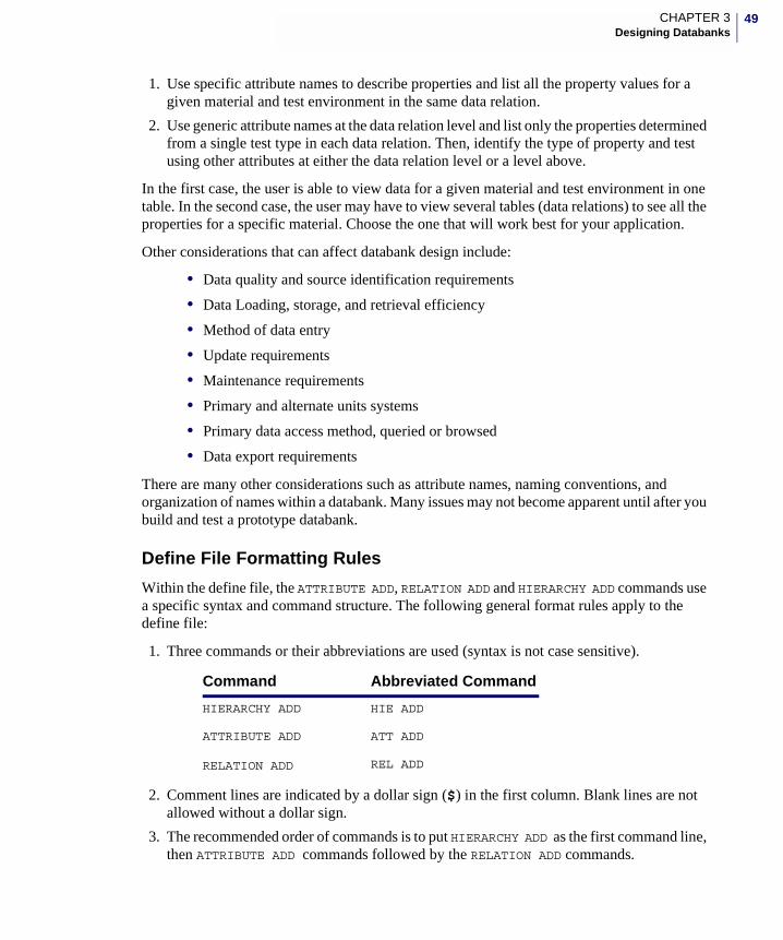
Within the define file, the ATTRIBUTE ADD, RELATION ADD and HIERARCHY ADD commands use a specific syntax and command structure. The following general format rules apply to the define file:
1. Three commands or their abbreviations are used (syntax is not case sensitive).
2. Comment lines are indicated by a dollar sign ($) in the first column. Blank lines are not allowed without a dollar sign.
3. The recommended order of commands is to put HIERARCHY ADD as the first command line, then ATTRIBUTE ADD commands followed by the RELATION ADD commands.
Command Abbreviated Command
HIERARCHY ADD HIE ADD
ATTRIBUTE ADD ATT ADD
RELATION ADD REL ADD
50
4. An ATTRIBUTE ADD command must precede a RELATION ADD command which uses the attribute.
5. Command parameters can be separated using spaces, commas, or tabs.
6. Commands are limited to a total of 2000 characters. For convenience in editing or printing, divide longer command lines by placing a comma at the end of the line and continuing the command on the next line. Do not break the line in the middle of a string or parameter.
7. Quotes are required around all units and description fields. Strings with embedded blanks, such as,“Manufacturer Designation” are placed in quotes because of the space between the two words.
8. Attribute names and relation names must be unique. Names that differ only by uppercase or lowercase are not considered unique.
9. Attribute names and relation names must not begin with an underscore (_). The underscore character is reserved by MSC.Mvision as the first character of internally defined attributes. An underscore is valid anywhere else in the attribute name or relation. See defining attributes and defining relations for further restrictions on names.
10. The string -0- indicates null or nothing (as opposed to zero) when entered as a parameter in an attribute definition or a data value in an input file. A null string can also be designated by a space enclosed in quotes “ ”. The null string -0- is the preferred designation.
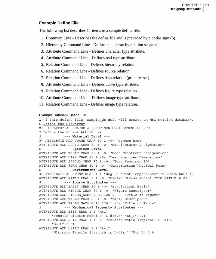
51CHAPTER 3Designing Databanks
Example Define File
The following list describes 11 items in a sample define file:
1. Comment Line - Describes the define file and is preceded by a dollar sign ($).
2. Hierarchy Command Line - Defines the hierarchy relation sequence.
3. Attribute Command Line - Defines character type attribute.
4. Attribute Command Line - Defines real type attribute.
5. Relation Command Line - Defines hierarchy relation.
6. Relation Command Line - Defines source relation.
7. Relation Command Line - Defines data relation (property set).
8. Attribute Command Line - Defines curve type attribute.
9. Relation Command Line - Defines figure type relation.
10. Attribute Command Line - Defines image type attribute.
11. Relation Command Line - Defines image type relation.
Example Databank Define File1) $ This define file, sample_db.def, will create an MSC.Mvision databank.$ Define the Hierarchy:2) HIERARCHY ADD MATERIAL SPECIMEN ENVIRONMENT SOURCE$ Define the Schema Attributes:$ --- Material Level ---3) ATTRIBUTE ADD CNAME CHAR 80 1 -0- "Common Name"ATTRIBUTE ADD DESIG CHAR 80 1 -0- "Manufacturer Designation"$ --- Specimen Level ---ATTRIBUTE ADD TREAT CHAR 80 1 -0- “Heat Treatment Designation"ATTRIBUTE ADD DIMS CHAR 80 1 -0- “Test Specimen Dimensions"ATTRIBUTE ADD SPECNO CHAR 80 1 -0- “Test Specimen ID"ATTRIBUTE ADD FORM CHAR 80 1 -0- “Construction/Physical Form"$ --- Environment Level ---4) ATTRIBUTE ADD TEMP REAL 1 1 "deg_F" “Test Temperature" “TEMPERATURE” 1.0ATTRIBUTE ADD RATIO REAL 1 1 -0- "Cyclic Stress Ratio" “SIG_RATIO” 0.01$ --- Source Attributes ---ATTRIBUTE ADD BASIS CHAR 80 1 -0- "Statistical Basis"ATTRIBUTE ADD FIGURE CHAR 80 1 -0- "Figure Descriptor"ATTRIBUTE ADD FIGURE_NAME CHAR 120 1 -0- "Title of Figure"ATTRIBUTE ADD TABLE CHAR 80 1 -0- "Table Descriptor"ATTRIBUTE ADD TABLE_NAME CHAR 120 1 -0- "Title of Table"$ --- Mechanical Property Attributes ---ATTRIBUTE ADD E11T REAL 1 1 “Msi”,
“Tensile Elastic Modulus (L-dir.)” “Et_L” 0.1ATTRIBUTE ADD NU12 REAL 1 1 -0- “Poisson ratio (inplane: L-LT)”,
“mu_L” 0.01ATTRIBUTE ADD US11T REAL 1 1 “ksi”,
“Ultimate Tensile Strength in L-dir.” “Ftu_L” 1.0
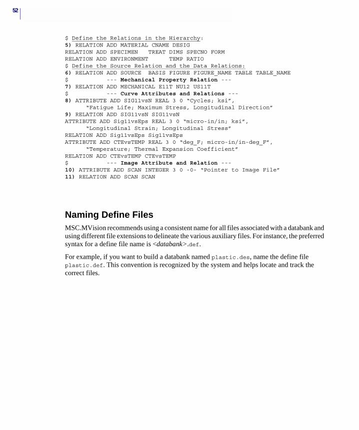
52
$ Define the Relations in the Hierarchy:5) RELATION ADD MATERIAL CNAME DESIGRELATION ADD SPECIMEN TREAT DIMS SPECNO FORMRELATION ADD ENVIRONMENT TEMP RATIO$ Define the Source Relation and the Data Relations:6) RELATION ADD SOURCE BASIS FIGURE FIGURE_NAME TABLE TABLE_NAME$ --- Mechanical Property Relation ---7) RELATION ADD MECHANICAL E11T NU12 US11T$ --- Curve Attributes and Relations ---8) ATTRIBUTE ADD SIG11vsN REAL 3 0 “Cycles; ksi”,
“Fatigue Life; Maximum Stress, Longitudinal Direction”9) RELATION ADD SIG11vsN SIG11vsNATTRIBUTE ADD Sig11vsEps REAL 3 0 “micro-in/in; ksi”,
“Longitudinal Strain; Longitudinal Stress”RELATION ADD Sig11vsEps Sig11vsEpsATTRIBUTE ADD CTEvsTEMP REAL 3 0 “deg_F; micro-in/in-deg_F”,
“Temperature; Thermal Expansion Coefficient”RELATION ADD CTEvsTEMP CTEvsTEMP$ --- Image Attribute and Relation ---10) ATTRIBUTE ADD SCAN INTEGER 3 0 -0- “Pointer to Image File”11) RELATION ADD SCAN SCAN
Naming Define FilesMSC.MVision recommends using a consistent name for all files associated with a databank and using different file extensions to delineate the various auxiliary files. For instance, the preferred syntax for a define file name is <databank>.def.
For example, if you want to build a databank named plastic.des, name the define file plastic.def. This convention is recognized by the system and helps locate and track the correct files.
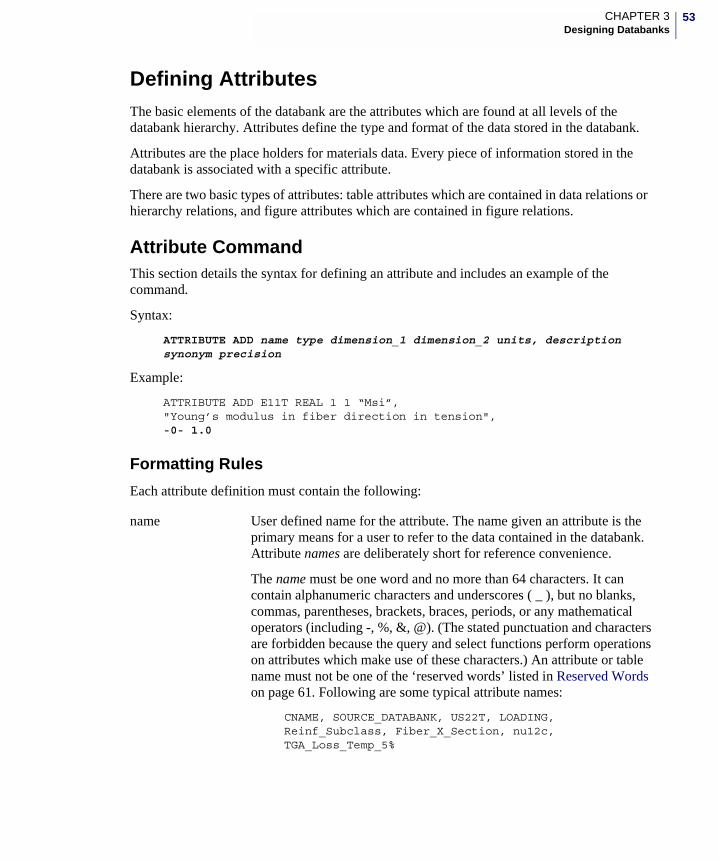
53CHAPTER 3Designing Databanks
Defining AttributesThe basic elements of the databank are the attributes which are found at all levels of the databank hierarchy. Attributes define the type and format of the data stored in the databank.
Attributes are the place holders for materials data. Every piece of information stored in the databank is associated with a specific attribute.
There are two basic types of attributes: table attributes which are contained in data relations or hierarchy relations, and figure attributes which are contained in figure relations.
Attribute CommandThis section details the syntax for defining an attribute and includes an example of the command.
Syntax:
ATTRIBUTE ADD name type dimension_1 dimension_2 units, description synonym precision
Example:
ATTRIBUTE ADD E11T REAL 1 1 “Msi”,"Young’s modulus in fiber direction in tension",-0- 1.0
Formatting Rules
Each attribute definition must contain the following:
name User defined name for the attribute. The name given an attribute is the primary means for a user to refer to the data contained in the databank. Attribute names are deliberately short for reference convenience.
The name must be one word and no more than 64 characters. It can contain alphanumeric characters and underscores ( _ ), but no blanks, commas, parentheses, brackets, braces, periods, or any mathematical operators (including -, %, &, @). (The stated punctuation and characters are forbidden because the query and select functions perform operations on attributes which make use of these characters.) An attribute or table name must not be one of the ‘reserved words’ listed in Reserved Words on page 61. Following are some typical attribute names:
CNAME, SOURCE_DATABANK, US22T, LOADING, Reinf_Subclass, Fiber_X_Section, nu12c, TGA_Loss_Temp_5%
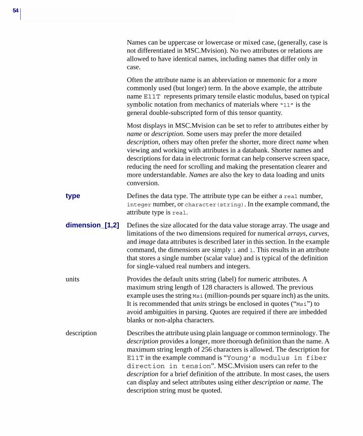
54
Names can be uppercase or lowercase or mixed case, (generally, case is not differentiated in MSC.Mvision). No two attributes or relations are allowed to have identical names, including names that differ only in case.
Often the attribute name is an abbreviation or mnemonic for a more commonly used (but longer) term. In the above example, the attribute name E11T represents primary tensile elastic modulus, based on typical symbolic notation from mechanics of materials where “11” is the general double-subscripted form of this tensor quantity.
Most displays in MSC.Mvision can be set to refer to attributes either by name or description. Some users may prefer the more detailed description, others may often prefer the shorter, more direct name when viewing and working with attributes in a databank. Shorter names and descriptions for data in electronic format can help conserve screen space, reducing the need for scrolling and making the presentation clearer and more understandable. Names are also the key to data loading and units conversion.
type Defines the data type. The attribute type can be either a real number, integer number, or character(string). In the example command, the attribute type is real.
dimension_[1,2] Defines the size allocated for the data value storage array. The usage and limitations of the two dimensions required for numerical arrays, curves, and image data attributes is described later in this section. In the example command, the dimensions are simply 1 and 1. This results in an attribute that stores a single number (scalar value) and is typical of the definition for single-valued real numbers and integers.
units Provides the default units string (label) for numeric attributes. A maximum string length of 128 characters is allowed. The previous example uses the string Msi (million-pounds per square inch) as the units. It is recommended that units strings be enclosed in quotes (“Msi”) to avoid ambiguities in parsing. Quotes are required if there are imbedded blanks or non-alpha characters.
description Describes the attribute using plain language or common terminology. The description provides a longer, more thorough definition than the name. A maximum string length of 256 characters is allowed. The description for E11T in the example command is “Young’s modulus in fiber direction in tension”. MSC.Mvision users can refer to the description for a brief definition of the attribute. In most cases, the users can display and select attributes using either description or name. The description string must be quoted.
55CHAPTER 3Designing Databanks
Table AttributesThere are four different types of table attributes:
• Scalar Attributes
• Array Attributes
synonym An alternate attribute name. Synonyms can be used for queries in place of attribute names. The rules for synonym names are the same as for attribute names.
The synonym specified in the example is -0- which means ‘null’ or no synonym which is the usual definition.
precision Precision is used to control display of real numerical values to the degree of accuracy appropriate for a given attribute, even after calculations such as units transformations.
Important: If precision is omitted or specified as zero, real number values are displayed with 16 significant digits.
Precision is defined separately for each attribute. For real attribute types, precision determines the nearest decimal value to which an attribute value is rounded when displayed or loaded. A precision of 0.001 shows a value of .23423 as .234. The sample attribute E11T above has precision specified as 1.0. Therefore, a value of 28.51 Msi is displayed as 29,and, if transformed to SI units, as 197 GPa. Precision can be omitted. The preferred syntax is -0-. If precision is not specified, the attribute values will be displayed to the most significant digit of the value.
The following should be considered when defining precision. If a databank contains values for an attribute that comes from a variety of sources or applies to a wide range of material types, enforcing a databank-wide precision value can be quite misleading. Also, queries operate on the displayed value, which, because of round-off, may be slightly different from the “true” (as originally loaded) value.
Situations like those described above are considered undesirable, and the precision parameter should be omitted from the attribute definition. In this case, MSC.Mvision determines an effective display precision based on each instance, rather than the same precision for all instances of an attribute.
Note: An absolute query for a number displayed with precision could fail due to the round-off difference. In general, when querying real number attributes, use relative queries or a range of values that includes enough tolerance to account for possible round-off.
56
• Character Attributes
• Full Text Attributes
Scalar Attributes
A scalar attribute is a single (real or integer) value. For example, a scalar attribute named US11T could represent ultimate strength. The value stored in the US11T attribute would be the measured or calculated value of a specific material. These attributes are defined with specific units and precision.
Scalar attributes contain a single value as reflected in the 1x1 array dimension in its definition. The attribute can be either an integer or real number. The following command defines a scalar attribute named TEMP:
ATTRIBUTE ADD TEMP REAL 1 1 "deg_F", "Temperature" "T" 0.01
The above defined attribute, TEMP, stores real numbers representing temperature in degrees Fahrenheit. T is a synonym for TEMP and the data has a precision of 0.01 degrees Fahrenheit.
For integer attributes, the command is INTEGER or the abbreviation INT. Units and precision do not apply and will be ignored if entered. The following command defines the TEMP attribute above as an integer:
ATT ADD TEMP INT 1 1 -0- “Temperature” “T” -0-
Array Attributes
An array attribute is a matrix of multiple numeric values. Array attributes are defined like scalar attributes, except that the dimension parameters define a storage array greater than 1 by 1. An array attribute has several possible uses within the MSC.Mvision databank.
The most obvious use is to store a matrix of real numbers, but array attributes are also used to store curve and image data (See Curve Attributes on page 58 and Figure Attributes on page 58 below).
The following command defines an array attribute:
ATTRIBUTE ADD STRAINS_GAGE REAL 3 1,"micro-in/in" "Strain Gage Values" -0- 0.01
This creates a 3 by 1 matrix for holding strains from a 60° strain rosette. The units are in 10-6 in/in with a precision of 10-8 in/in. The attribute is named STRAINS_GAGE. Scalar type array attributes are also referred to as matrix attributes. The first dimension specifies the number of columns. The second dimension specifies the number of rows. Note that this attribute has no synonym.
The maximum dimension for an array is only limited by the memory capacity of your particular system. Arrays must be fully loaded. If a 6 x 2000 array is defined, each instance is expected to be loaded with a total of 12000 numbers. Only real number arrays are allowed, except for the special integer arrays used to define image attributes.
57CHAPTER 3Designing Databanks
There are special considerations for attributes other than curves; unit conversions can be applied, but a single conversion factor is applied to all values in the matrix. Multiple unit and description strings are not supported. Only one precision parameter is allowed and applied to all values.
It is common practice to define a range of values by using single numeric scalar values in an attribute with a suffix of _min, _max or _nom.
Character Attributes
A character attribute is a string of ASCII characters. Character attributes store data directly in the databank.
Character attributes store data in the form of text strings. The definition specifies a one-dimensional array of type CHAR. The first dimension prescribes the maximum number of characters (up to a limit of 2000) to allow in a given string value. The dimension must be large enough to handle the longest anticipated text string, but should be limited to conserve memory and trap a string entered in error. A character attribute is defined as follows:
ATTRIBUTE ADD MFG CHAR 60 1 -0- "Manufacturer"
In this example, the character attribute is named MFG and stores the name of the material’s manufacturer. Strings loaded in MFG can be up to 60 characters in length. Note that character attributes do not use units or precision parameters and, if entered, values are ignored.
Full-Text Attributes
Full-Text Attributes reference an external text file and are defined as a special case of character attribute. Full-text attributes allow formatted external files to be referenced and displayed intact. This provides a useful alternative to character attributes, which store data directly in the databank.
The advantages of using full-text attributes is that this file can be stored independent of the databank, and updated or edited without accessing the databank. A referenced file can be of any format and not just a text file. Disadvantages are that the external file is not subject to the same protections and privileges as the databank, and the contents of the external file cannot be queried directly.
It is usually more efficient to define large blocks of text as full text attributes. Because the external text file is referenced (linked) rather than including the information directly in the databank. The default action is to display the external file using a text window built into
Note: If possible, use real number or integer attributes (rather than character attributes), to store numeric information. Numbers stored in character attributes are treated as text. This makes the values unavailable for mathematical operations and queries. If a small percentage of instances require text for explanation, consider loading the data as null values (-0-), and use footnotes for the required text.
58
MSC.Mvision. Via the Helper function, you can use an external program of your own choice to display the external file. This allows non-text files to display images or other special types of files.
The syntax (keyword) used to distinguish full text attributes from regular character attributes is the string TEXT: placed at the beginning of the description parameter, as shown below:
ATT ADD FAB_CHARS CHAR 80 1 -0- “TEXT: Fabrication characteristics”
Instances of a full text attribute are file names. This can be the full path or the relative path from the location of the databank. For example, a typical entry in the input file might be:
FAB_CHARS = docs/fab0001.doc
where docs is a directory directly below the directory in which the databank resides and fab0001.doc is the name of the text file. The string dimension (80 in the example) must be large enough to handle the longest anticipated file name. The amount of data in the referenced files is unlimited.
Full text data objects appear as icons in the Materials Browser or property sets displayed in the Data Viewer. When selected, the contents are displayed in a separate text window. This is the default action for a full text attribute and is only useful if the file contains text. Using the Helper application feature, you can display the external file using an external program. This allows you to store references to image files and display them with an image viewing tool.
The full text data type is discussed in detail in Chapter 4.
Figure Attributes
Curves and images are special numeric arrays that store data which can be graphically displayed and are referred to as figure attributes.
Figure attributes are of two different types described in the following sections:
• Curve Attributes
• Image Attributes
A number of conventions have been developed that support various types of these unique data objects. You can use these simple techniques to represent most kinds of graphical data associated with materials.
Curve Attributes
A curve attribute is a numeric array referencing a set of X-Y data points stored in the databank as a curve. The curve attribute is a special type of real array. For example:
ATTRIBUTE ADD CPvsTEMP REAL 3 0,“deg_F; BTU/lb-deg_F” “Temperature; Specific Heat”
Using the following rules, the above example defines a curve attribute called CPvsTEMP which is described as the plot of “Specific Heat versus Temperature”. The units given for Specific Heat are Btu/lb-deg_F and the units for Temperature are deg_F.
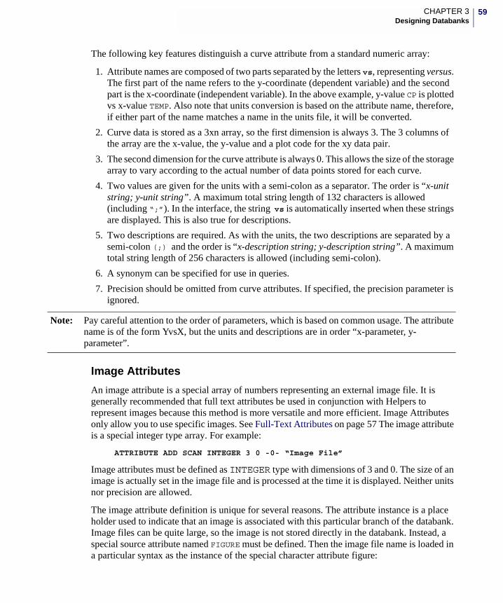
59CHAPTER 3Designing Databanks
The following key features distinguish a curve attribute from a standard numeric array:
1. Attribute names are composed of two parts separated by the letters vs, representing versus. The first part of the name refers to the y-coordinate (dependent variable) and the second part is the x-coordinate (independent variable). In the above example, y-value CP is plotted vs x-value TEMP. Also note that units conversion is based on the attribute name, therefore, if either part of the name matches a name in the units file, it will be converted.
2. Curve data is stored as a 3xn array, so the first dimension is always 3. The 3 columns of the array are the x-value, the y-value and a plot code for the xy data pair.
3. The second dimension for the curve attribute is always 0. This allows the size of the storage array to vary according to the actual number of data points stored for each curve.
4. Two values are given for the units with a semi-colon as a separator. The order is “x-unit string; y-unit string”. A maximum total string length of 132 characters is allowed (including “;”). In the interface, the string vs is automatically inserted when these strings are displayed. This is also true for descriptions.
5. Two descriptions are required. As with the units, the two descriptions are separated by a semi-colon (;) and the order is “x-description string; y-description string”. A maximum total string length of 256 characters is allowed (including semi-colon).
6. A synonym can be specified for use in queries.
7. Precision should be omitted from curve attributes. If specified, the precision parameter is ignored.
Image Attributes
An image attribute is a special array of numbers representing an external image file. It is generally recommended that full text attributes be used in conjunction with Helpers to represent images because this method is more versatile and more efficient. Image Attributes only allow you to use specific images. See Full-Text Attributes on page 57 The image attribute is a special integer type array. For example:
ATTRIBUTE ADD SCAN INTEGER 3 0 -0- “Image File”
Image attributes must be defined as INTEGER type with dimensions of 3 and 0. The size of an image is actually set in the image file and is processed at the time it is displayed. Neither units nor precision are allowed.
The image attribute definition is unique for several reasons. The attribute instance is a place holder used to indicate that an image is associated with this particular branch of the databank. Image files can be quite large, so the image is not stored directly in the databank. Instead, a special source attribute named FIGURE must be defined. Then the image file name is loaded in a particular syntax as the instance of the special character attribute figure:
Note: Pay careful attention to the order of parameters, which is based on common usage. The attribute name is of the form YvsX, but the units and descriptions are in order “x-parameter, y-parameter”.
60
FIGURE= SCAN FILE: ../image.txt
Creating AttributesThe following lists the steps to create and name attributes for your define file.
1. For each material or material type, identify the required data elements (attributes) to identify, characterize, or qualify the property values. Attributes will be easy to identify if you use one of the following categories:
• Material Characteristic
• Data Source
• Test parameter, condition, method, and detail.
• Property value including single point values, curves (arrays), images, and text files.
2. For each attribute, provide the following information:
• Define the attribute type; character string, real values, curve, array, text file, or image.
• Define the units in the context of the unit system for the entire databank.
• Provide a description which is a definition of the attribute name.
• Define the appropriate precision for data values in the databank.
• Define synonyms for the attributes if desired.
• Where applicable, specify the data constraints to identify data that is out of range.
• Define test information to be incorporated in the attribute name. See Recommended Naming Conventions.
• Identify information for attributes to be documented in the online help.
• Identify test specifications, conditions, or identification that applies to all property attributes.
• Provide quality indicators or qualifiers for property data.
This information is needed to write the schema input files and is useful when verifying the databank.
Naming Attributes Attribute names are involved in most aspects of working with a databank, although display features allow using either the name or the description. It is best to use attribute names that provide the user with clues about the contents of the attribute.
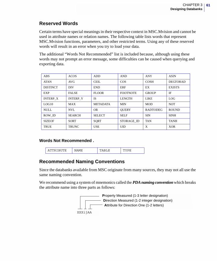
61CHAPTER 3Designing Databanks
Reserved Words
Certain terms have special meanings in their respective context in MSC.Mvision and cannot be used in attribute names or relation names. The following table lists words that represent MSC.Mvision functions, parameters, and other restricted terms. Using any of these reserved words will result in an error when you try to load your data.
The additional “Words Not Recommended” list is included because, although using these words may not prompt an error message, some difficulties can be caused when querying and exporting data.
Words Not Recommended .
Recommended Naming Conventions
Since the databanks available from MSC originate from many sources, they may not all use the same naming convention.
We recommend using a system of mnemonics called the PDA naming convention which breaks the attribute name into three parts as follows:
ABS ACOS ADD AND ANY ASIN
ATAN AVG CEIL COS COSH DEGTORAD
DISTINCT DIV END ERF EX EXISTS
EXP FALSE FLOOR FOOTNOTE GROUP IF
INTERP_X INTERP_Y IS LENGTH LIKE LOG
LOG10 MAX METADATA MIN MOD NOT
NULL NVL OR QUERY RADTODEG ROUND
ROW_ID SEARCH SELECT SELF SIN SINH
SIZEOF SORT SQRT STORAGE_ID TAN TANH
TRUE TRUNC USE UID X XOR
ATTRIBUTE NAME TABLE TYPE
XXXijAA
Property Measured (1-3 letter designation)Direction Measured (1-2 integer designation)Attribute for Direction One (1-2 letters)
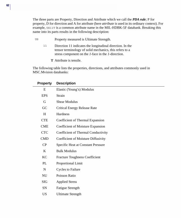
62
The three parts are Property, Direction and Attribute which we call the PDA rule; P for property, D for direction and A for attribute (here attribute is used in its ordinary context). For example, US11T is a common attribute name in the MIL-HDBK-5F databank. Breaking this name into its parts results in the following description:
The following table lists the properties, directions, and attributes commonly used in MSC.Mvision databanks:
US Property measured is Ultimate Strength.
11 Direction 11 indicates the longitudinal direction. In the tensor terminology of solid mechanics, this refers to a stress component on the 1-face in the 1-direction.
T Attribute is tensile.
Property Description
E Elastic (Young’s) Modulus
EPS Strain
G Shear Modulus
GC Critical Energy Release Rate
H Hardness
CTE Coefficient of Thermal Expansion
CME Coefficient of Moisture Expansion
CTC Coefficient of Thermal Conductivity
CMD Coefficient of Moisture Diffusivity
CP Specific Heat at Constant Pressure
K Bulk Modulus
KC Fracture Toughness Coefficient
PL Proportional Limit
N Cycles to Failure
NU Poisson Ratio
SIG Applied Stress
SN Fatigue Strength
US Ultimate Strength
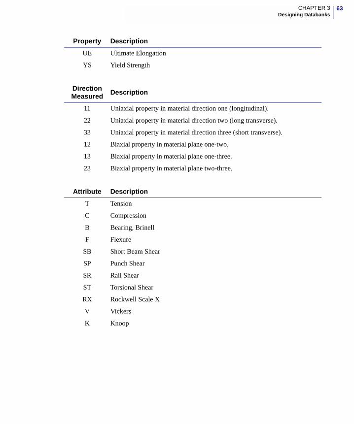
63CHAPTER 3Designing Databanks
UE Ultimate Elongation
YS Yield Strength
Direction Measured Description
11 Uniaxial property in material direction one (longitudinal).
22 Uniaxial property in material direction two (long transverse).
33 Uniaxial property in material direction three (short transverse).
12 Biaxial property in material plane one-two.
13 Biaxial property in material plane one-three.
23 Biaxial property in material plane two-three.
Attribute Description
T Tension
C Compression
B Bearing, Brinell
F Flexure
SB Short Beam Shear
SP Punch Shear
SR Rail Shear
ST Torsional Shear
RX Rockwell Scale X
V Vickers
K Knoop
Property Description
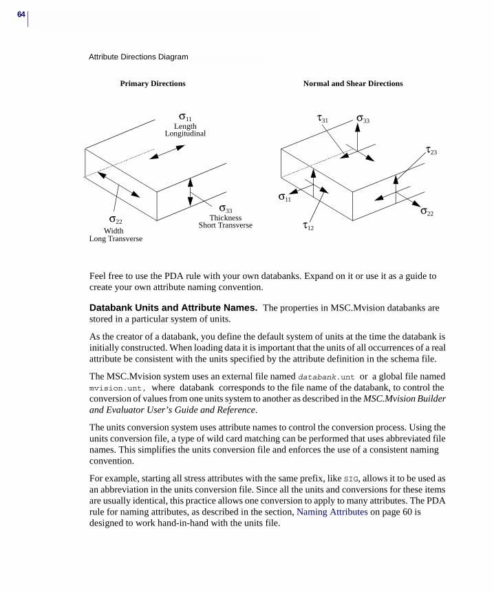
64
Feel free to use the PDA rule with your own databanks. Expand on it or use it as a guide to create your own attribute naming convention.
Databank Units and Attribute Names. The properties in MSC.Mvision databanks are stored in a particular system of units.
As the creator of a databank, you define the default system of units at the time the databank is initially constructed. When loading data it is important that the units of all occurrences of a real attribute be consistent with the units specified by the attribute definition in the schema file.
The MSC.Mvision system uses an external file named databank.unt or a global file named mvision.unt, where databank corresponds to the file name of the databank, to control the conversion of values from one units system to another as described in the MSC.Mvision Builder and Evaluator User’s Guide and Reference.
The units conversion system uses attribute names to control the conversion process. Using the units conversion file, a type of wild card matching can be performed that uses abbreviated file names. This simplifies the units conversion file and enforces the use of a consistent naming convention.
For example, starting all stress attributes with the same prefix, like SIG, allows it to be used as an abbreviation in the units conversion file. Since all the units and conversions for these items are usually identical, this practice allows one conversion to apply to many attributes. The PDA rule for naming attributes, as described in the section, Naming Attributes on page 60 is designed to work hand-in-hand with the units file.
σ11Length
Longitudinal
σ33Thickness
Short Transverseσ22
WidthLong Transverse
Primary Directions Normal and Shear Directions
τ31 σ33
τ23
σ22
τ12
σ11
Attribute Directions Diagram

65CHAPTER 3Designing Databanks
Curves are a special case for the units file. The units conversion interprets curve attributes as two attributes joined by the string vs. The units conversion utility breaks the curve attribute into its parts and compares the parts to the attribute definitions in the databank.unt file. For this reason, your curve and scalar attributes must be based on the same naming convention.
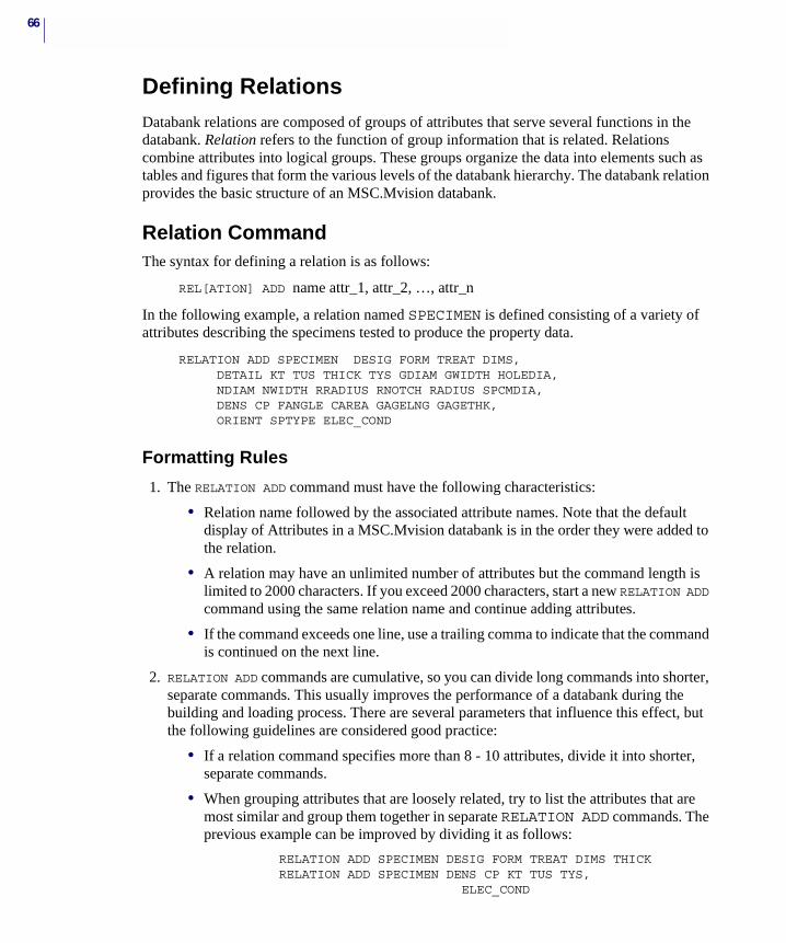
66
Defining RelationsDatabank relations are composed of groups of attributes that serve several functions in the databank. Relation refers to the function of group information that is related. Relations combine attributes into logical groups. These groups organize the data into elements such as tables and figures that form the various levels of the databank hierarchy. The databank relation provides the basic structure of an MSC.Mvision databank.
Relation CommandThe syntax for defining a relation is as follows:
REL[ATION] ADD name attr_1, attr_2, …, attr_n
In the following example, a relation named SPECIMEN is defined consisting of a variety of attributes describing the specimens tested to produce the property data.
RELATION ADD SPECIMEN DESIG FORM TREAT DIMS, DETAIL KT TUS THICK TYS GDIAM GWIDTH HOLEDIA,
NDIAM NWIDTH RRADIUS RNOTCH RADIUS SPCMDIA, DENS CP FANGLE CAREA GAGELNG GAGETHK,
ORIENT SPTYPE ELEC_COND
Formatting Rules
1. The RELATION ADD command must have the following characteristics:
• Relation name followed by the associated attribute names. Note that the default display of Attributes in a MSC.Mvision databank is in the order they were added to the relation.
• A relation may have an unlimited number of attributes but the command length is limited to 2000 characters. If you exceed 2000 characters, start a new RELATION ADD command using the same relation name and continue adding attributes.
• If the command exceeds one line, use a trailing comma to indicate that the command is continued on the next line.
2. RELATION ADD commands are cumulative, so you can divide long commands into shorter, separate commands. This usually improves the performance of a databank during the building and loading process. There are several parameters that influence this effect, but the following guidelines are considered good practice:
• If a relation command specifies more than 8 - 10 attributes, divide it into shorter, separate commands.
• When grouping attributes that are loosely related, try to list the attributes that are most similar and group them together in separate RELATION ADD commands. The previous example can be improved by dividing it as follows:
RELATION ADD SPECIMEN DESIG FORM TREAT DIMS THICK RELATION ADD SPECIMEN DENS CP KT TUS TYS,
ELEC_COND
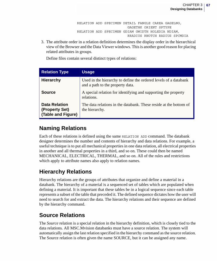
67CHAPTER 3Designing Databanks
RELATION ADD SPECIMEN DETAIL FANGLE CAREA GAGELNG,GAGETHK ORIENT SPTYPE
RELATION ADD SPECIMEN GDIAM GWIDTH HOLEDIA NDIAM, RRADIUS RNOTCH RADIUS SPCMDIA
3. The attribute order in a relation definition determines the display order in the hierarchical view of the Browser and the Data Viewer windows. This is another good reason for placing related attributes in groups.
Define files contain several distinct types of relations:
Naming RelationsEach of these relations is defined using the same RELATION ADD command. The databank designer determines the number and contents of hierarchy and data relations. For example, a useful technique is to put all mechanical properties in one data relation, all electrical properties in another and all thermal properties in a third, and so on. These could then be named MECHANICAL, ELECTRICAL, THERMAL, and so on. All of the rules and restrictions which apply to attribute names also apply to relation names.
Hierarchy RelationsHierarchy relations are the groups of attributes that organize and define a material in a databank. The hierarchy of a material is a sequenced set of tables which are populated when defining a material. It is important that these tables be in a logical sequence since each table represents a subset of the table that preceded it. The defined sequence dictates how the user will need to search for and extract the data. The hierarchy relations and their sequence are defined by the hierarchy command.
Source RelationsThe Source relation is a special relation in the hierarchy definition, which is closely tied to the data relations. All MSC.Mvision databanks must have a source relation. The system will automatically assign the last relation specified in the hierarchy command as the source relation. The Source relation is often given the name SOURCE, but it can be assigned any name.
Relation Type Usage
Hierarchy Used in the hierarchy to define the ordered levels of a databank and a path to the property data.
Source A special relation for identifying and supporting the property relations.
Data Relation (Property Set)(Table and Figure)
The data relations in the databank. These reside at the bottom of the hierarchy.
68
The source relation is intended to store information regarding the origins (source) of the data and attributes. Any attribute which must apply to multiple relations can be included in the source relation.
Working with source attributes can be very powerful, if handled properly. But, if not correctly applied, using source attributes can produce misleading or unexpected results. Source attributes are automatically displayed in the property tables when tables are displayed. They are displayed in the Pedigree when images and figures are displayed in the Data Viewer window. Source attributes may also be used as columns in the Materials Browser window, using the Edit - Material Set... menu option or when used as a column header in the Browser. If data relations for selected materials have values for source attributes, they will be displayed.
If property sets have different values for any source attribute, all values are displayed (separated by a comma) in the same row of the Browser display. This allows you to easily work with groups of tables and figures that may differ in one or more source attribute value. Therefore, a query that satisfies one of the source attribute values returns all the tables and figures for the row in which that value is found, even though there may be some tables and figures in that row which the query has not satisfied.
Querying source attributes are subject to automatic binding in the MSC.Mvision system. The system attempts to determine which data relation you are querying; usually it is assumed to be the last relation that was addressed. Due to this automatic binding, it is best to query source attributes directly whenever possible. The form of this direct query is:
_relation_name.source_attribute_name
You should keep in mind the many implications to be considered involving querying for attributes in source relations and when assigning an attribute to the source relation.
Data RelationsMSC.Mvision has two types of data relations: Table and Figure. These are named for the type of information that they contain. These types of data relations are distributed tables directly below the MSC.Mvision databank hierarchy levels. Data relations are also referred to as property sets.
Note: By default, any named relation which is not included in the hierarchy command is a data relation (property set).
Note: New, in MSC.Mvision 2006, is the option to Apply Query for Property Sets. When this option is toggled “on”, the query on the Source attribute becomes unambiguous. This means that if the user queries for a material with a specific value of an attribute stored in the Source, only the property tables that satisfy the query will be displayed for the materials that meet the query specification. However, due to the complexity of the way that Source attributes are handled in a query, it is recommended that you store attributes such as ‘Test Temperature’, ‘Strain Rate’, or ‘Load Conditions’, for which there are potentially many variants for a material specimen, in a relation above the Source.
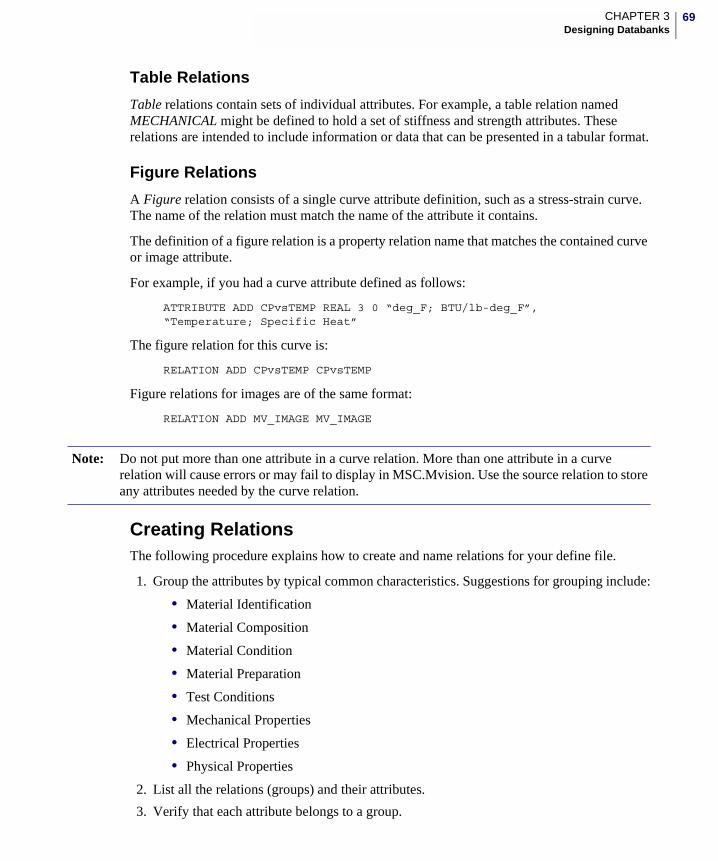
69CHAPTER 3Designing Databanks
Table Relations
Table relations contain sets of individual attributes. For example, a table relation named MECHANICAL might be defined to hold a set of stiffness and strength attributes. These relations are intended to include information or data that can be presented in a tabular format.
Figure Relations
A Figure relation consists of a single curve attribute definition, such as a stress-strain curve. The name of the relation must match the name of the attribute it contains.
The definition of a figure relation is a property relation name that matches the contained curve or image attribute.
For example, if you had a curve attribute defined as follows:
ATTRIBUTE ADD CPvsTEMP REAL 3 0 “deg_F; BTU/lb-deg_F”,“Temperature; Specific Heat”
The figure relation for this curve is:
RELATION ADD CPvsTEMP CPvsTEMP
Figure relations for images are of the same format:
RELATION ADD MV_IMAGE MV_IMAGE
Creating RelationsThe following procedure explains how to create and name relations for your define file.
1. Group the attributes by typical common characteristics. Suggestions for grouping include:
• Material Identification
• Material Composition
• Material Condition
• Material Preparation
• Test Conditions
• Mechanical Properties
• Electrical Properties
• Physical Properties
2. List all the relations (groups) and their attributes.
3. Verify that each attribute belongs to a group.
Note: Do not put more than one attribute in a curve relation. More than one attribute in a curve relation will cause errors or may fail to display in MSC.Mvision. Use the source relation to store any attributes needed by the curve relation.

70
4. Provide a name for each group of attributes.
5. List all the relations (groups) in a logical sequence.
71CHAPTER 3Designing Databanks
Defining the HierarchyThe hierarchy command defines the basic framework of the databank. Each level in the hierarchy is composed of a single relation, referred to as a hierarchy relation. At the bottom of the hierarchy levels are the data relations.
The databank hierarchy defines the sequence of relations within the databank. The hierarchy forms the basic databank schema by binding the relations into a logical sequence that determines how the user accesses the data.
Hierarchy CommandThe syntax for defining the databank hierarchy is as follows:
HIE[RARCHY] ADD rel_1 rel_2 … rel_n source
Example:
HIE ADD MATERIAL SPECIMEN ENVIRONMENT ORIGIN
The hierarchy command specifies the relations intended to form the databank hierarchy.
Formatting Rules
• Up to 32 levels are permitted in a databank.
• Enter relations in order from the highest level to the lowest level left to right on the command line.
• The last relation in the hierarchy command is always the source relation, regardless of its name.
• The source relation does not count as one of the 32 levels. In the example above, there are three levels to the hierarchy: MATERIAL SPECIMEN, ENVIRONMENT, and a source relation named ORIGIN.
• Any named relation in a define file, which is not specified in the hierarchy command is a data relation (property set).
Creating HierarchyThe following procedure explains how to create and name the hierarchy for your define file.
1. Separate the relations into groups. Relations that identify, define, and qualify materials in one group and relations that are property values of the materials in another group.
2. Organize these non property value relations in order of importance within their respective groups.
Note: The hierarchy command is used only once in a define file. Unlike the attribute and relation commands, there is no way to interactively modify the hierarchy once it is created. To change a databank hierarchy, you must change the define file and rebuild the databank.

72
3. List relations in a logical sequence and build a prototype databank using the defined hierarchy.
73CHAPTER 3Designing Databanks
MSC.Mvision Unique IdentifierAs of version 2002 a MSC.Mvision databank contains a UID (Global Unique Identifier) for every table row within the databank. This UID is a special property of each table row within the databank that is automatically created upon creation of the databank. The UID can be modified using the MSC.Mvision Builder or the MvBatchBuilder, but can not be assigned or modified using the DPI or the spreadsheet functions.
The UID consists of three elements:
• Table name - Name of the table for which the table row is a member.
• Name space- A character string not to exceed 64 characters and by default is the name of the databank file for which the database was originally created.
The name space can be one of two types: a database managed name space (default name space) or a user managed name space.
• A database managed name space is associated with a specific database and is automatically generated; this is the type of name space created when a database is initialized. If a valid name space cannot be derived from the file name then the name "default" is assigned.
• A user managed name space is controlled by the user who specifies the identifiers associated with the specific table rows. A valid name space is any character string that does not exceed 64 characters, does not include any symbols other than "_", must not begin with and "_" and must include at least one non-numeric character.
• integer row identifier (external-id), and table_name-name_space-external_id, such as, material-default-1. The row identifier is an integer value that combined with the name space is unique to the table for which the table row is a member. When the row identifiers are automatically generated they are a consecutive series of integers. The “as generated row identifier” is the internal_id. If you modify the UID then an external_id is created otherwise both the internal_id and external_id are the same. The name space and/or row identifier can be modified via the MSC.Mvision Builder or the MvBatchBuilder.
The UID can be used in query expressions to quickly locate specific table rows. The databank creator can assign the uid when loading a databank by specifying the UID in the input file. The UID can also be modified by updating the databank via an input file. The UID cannot be modified or specified using spreadsheet "put" or "modify" commands.
The UID can be used to create a specific subset of data within a databank by specifying the "namespace" component of the UID. If specific table rows in the lowest level hierarchy table are specified with a unique "namespace' then these materials can be easily accessed in a query for the specified "namespace'. The UID can also be used in an input file to locate or update a specific table row, providing very fast precision access for adding or updating tables and

74
attributes. The UID is automatically written to export files for version 2002 MSC.Mvision.This provides a direct reference to the data that was exported and a method to query the specific data accessed.
MSC.Mvision Builder and Evaluator 2002 Installation Guide
4 Creating Databanks
� Overview
� Initializing Databanks
� Constructing Data Input Files
� Processing Input Files
� Creating Prototypes
� Data Loading Methods
� Saving Databanks
76
Overview After you have completed all the preliminary work for creating a databank including planning and organizing the project, defining the attributes, relations, and hierarchy, and creating the define file, you are ready to perform the remaining databank steps.
Initializing DatabanksInitializing an MSC.Mvision Databank is a Builder Function that creates a databank structure from a define file. This structure does not contain any data. It is a skeleton databank.
The process of initializing a databank from a define file is outlined in the following steps.
1. Start MSC.Mvision Builder from a working directory (preferably the one containing your define file).
2. Click on the File - Builder Functions - New Databank to display the New Databank form.
3. The name of your define file displays in the box titled Choose a Define/Input File (assuming the file name suffix is def).
If there is more than one define file in the directory:
4. Click on the black triangle button next to the file name and select the correct file. (If the file resides in another directory, use the Browse button to navigate to the other directory and select the file.)
The default name for the databank displays in the Databank Name box. The default file name has a .des extension. For example, if your define file name is test.def, the databank name is test.des.
If you want to give it another name:
5. Click on the name and edit it, or use the accompanying Browse button to navigate to an existing databank to overwrite.
6. Use the Buffer Size button to increase the memory buffer. This may improve loading performance for larger databanks, but is usually not required.
7. Click on the button Check Only.
Important: Previous to MSC.Mvision 2006, MSC.Mvision Builder created platform dependent binary formats, commonly referred to as Big Endian and Little Endian. As of the 2006 release, MSC.Mvision Builder creates a single binary format which can be used on both platforms. While MSC.Mvision Builder and Evaluator 2006 can read the binary formats from previousversions of MSC.Mvision Builder, the reverse is not true.
Note: Note that you can perform this function whether or not you are ready to load data into the databank because initializing a databank is a completely separate step and doesn’t require the input data.
77CHAPTER 4Creating Databanks
Whether operation is check only or not, checking is always performed anytime a define file is read and the results returned to the status window.
8. If you have compiled input data files and are ready to load them, you can now select those files in the box marked Choose Input/Data File(s) to Read by clicking on the file name. If you are not loading data, ignore this step.
9. In the Report Message Status section, choose Summary or Detailed Messages for the status of the databank initialization. Detailed messages display all information warning and error messages for the current operation.
10. If the Write to Log File button is active, messages will be written in a file named builder.log in your current directory.
11. Click the Ok button when ready to proceed with databank initialization.
The databank is not created if there are errors in the define file. If the creation is successful, the New Databank window closes automatically and returns you to the Materials Browser window. A popup window confirms success or failure.
If the databank does not initialize, continue to edit and rerun the define file until you successfully create the initialized databank. If there are errors in the define file, you can edit it without exiting by clicking the Edit button in the Define File section of the form. If the default editor preference is set to vi, then the system invokes the UNIX vi editor in a shell window.
After a define file is read, you can review the messages in the Status window.Edit the file and exit vi to return to the New Databank form.
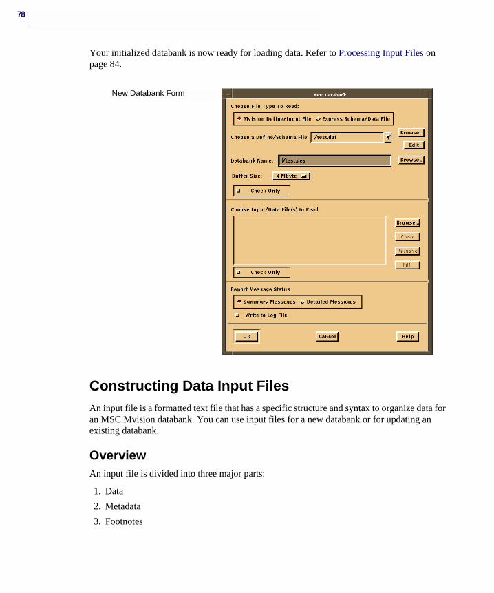
78
Your initialized databank is now ready for loading data. Refer to Processing Input Files on page 84.
Constructing Data Input FilesAn input file is a formatted text file that has a specific structure and syntax to organize data for an MSC.Mvision databank. You can use input files for a new databank or for updating an existing databank.
OverviewAn input file is divided into three major parts:
1. Data
2. Metadata
3. Footnotes
New Databank Form
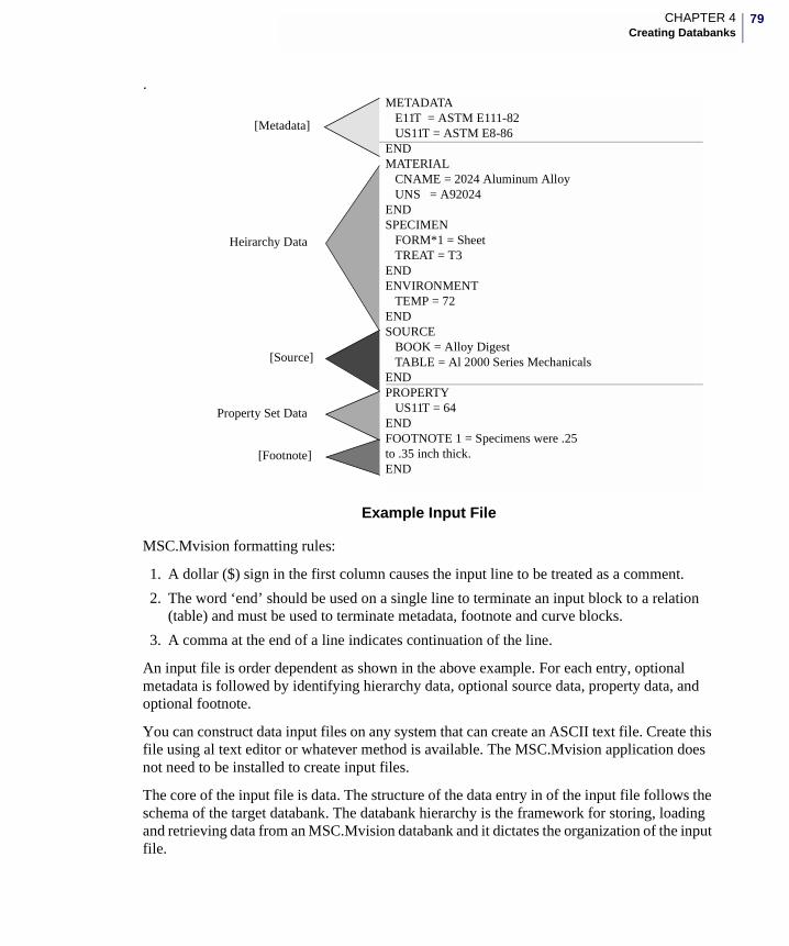
79CHAPTER 4Creating Databanks
.
Example Input File
MSC.Mvision formatting rules:
1. A dollar ($) sign in the first column causes the input line to be treated as a comment.
2. The word ‘end’ should be used on a single line to terminate an input block to a relation (table) and must be used to terminate metadata, footnote and curve blocks.
3. A comma at the end of a line indicates continuation of the line.
An input file is order dependent as shown in the above example. For each entry, optional metadata is followed by identifying hierarchy data, optional source data, property data, and optional footnote.
You can construct data input files on any system that can create an ASCII text file. Create this file using al text editor or whatever method is available. The MSC.Mvision application does not need to be installed to create input files.
The core of the input file is data. The structure of the data entry in of the input file follows the schema of the target databank. The databank hierarchy is the framework for storing, loading and retrieving data from an MSC.Mvision databank and it dictates the organization of the input file.
METADATAE11T = ASTM E111-82US11T = ASTM E8-86
ENDMATERIAL
CNAME = 2024 Aluminum AlloyUNS = A92024
ENDSPECIMEN
FORM*1 = SheetTREAT = T3
ENDENVIRONMENT
TEMP = 72ENDSOURCE
BOOK = Alloy DigestTABLE = Al 2000 Series Mechanicals
ENDPROPERTY
US11T = 64ENDFOOTNOTE 1 = Specimens were .25 to .35 inch thick.END
[Metadata]
[Footnote]
Heirarchy Data
[Source]
Property Set Data
80
In addition to data, the other features of an input file are metadata and footnotes. These features complement storing materials data in an MSC.Mvision databank. Metadata and footnote text are displayed with the data value for specified attributes in the Browser and Data Viewer windows.
Metadata is a superset of text data which is attached to all attributes of a specific type in the input file and may apply to all or a portion of the attributes in the databank. Metadata is applicable only to attributes defined as real. For example, metadata could be an ASTM, ISO or DIN test number or a data qualifier. Metadata is created when data is loaded into the databank.
Footnotes typically qualify a specific data entry within a databank. They are commonly used to attach a comment or add auxiliary information to a data value. An example of a footnote for ultimate strength could be, “Max. observed value, not ultimate.” Footnotes are added to the databank when data is loaded.
DataThe data section of the input file is structured as follows:
• Relation name listed in hierarchical order.
• Attribute names which have been assigned to this relation.
• Data values to be loaded for the named attributes.
To identify the attributes to be loaded, the highest relation in the databank hierarchy is listed with appropriate attributes and values. Followed by a similar set for the next relation in the hierarchy until all the data required for the current loading has been entered. A complete entry consists of a set of defined hierarchy relations and attributes, the source level relations and attributes, and data relations and attributes.
The source relation in input files is optional if no source attribute definitions are required. As of version 2002, source level attributes can be defined for a specific property set data relation by defining the required attribute within the property set data relation. In the previous example, attributes book and table could be included in the property relation.
The end of each set of data is marked with the term END. Although it is not absolutely required, using the END statement is recommended to insure that the databank loader module recognizes the end of each set of data.
To enhance readability and ease in editing, indent the text and use the END statement as shown in the input file example. The general syntax of a data entry is:
relation_name attribute_name [optional footnote number] = value expressed as text stringend
Assuming that the sample input file shown above is the first set of data loaded into a new databank, the effect is the creation of a new entry in the databank for each of the relations: MATERIAL, SPECIMEN, ENVIRONMENT, SOURCE, and PROPERTY. It is not necessary for all attributes of a relation to appear in each load statement. Null entries are automatically inserted for all attributes that are not set by the input file.
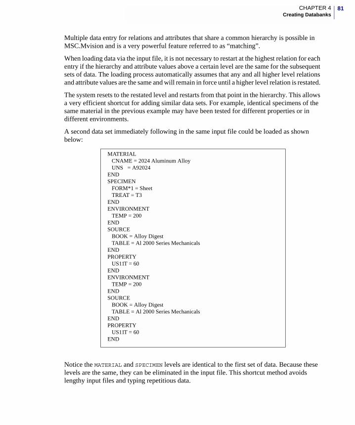
81CHAPTER 4Creating Databanks
Multiple data entry for relations and attributes that share a common hierarchy is possible in MSC.Mvision and is a very powerful feature referred to as “matching”.
When loading data via the input file, it is not necessary to restart at the highest relation for each entry if the hierarchy and attribute values above a certain level are the same for the subsequent sets of data. The loading process automatically assumes that any and all higher level relations and attribute values are the same and will remain in force until a higher level relation is restated.
The system resets to the restated level and restarts from that point in the hierarchy. This allows a very efficient shortcut for adding similar data sets. For example, identical specimens of the same material in the previous example may have been tested for different properties or in different environments.
A second data set immediately following in the same input file could be loaded as shown below:
Notice the MATERIAL and SPECIMEN levels are identical to the first set of data. Because these levels are the same, they can be eliminated in the input file. This shortcut method avoids lengthy input files and typing repetitious data.
MATERIALCNAME = 2024 Aluminum AlloyUNS = A92024
ENDSPECIMEN
FORM*1 = SheetTREAT = T3
ENDENVIRONMENT
TEMP = 200ENDSOURCE
BOOK = Alloy DigestTABLE = Al 2000 Series Mechanicals
ENDPROPERTY
US11T = 60ENDENVIRONMENT
TEMP = 200ENDSOURCE
BOOK = Alloy DigestTABLE = Al 2000 Series Mechanicals
ENDPROPERTY
US11T = 60END
82
at
r e
MetadataThe term metadata refers in general to information that explains, qualifies, or adds meaning to other data. Metadata can consist of items such as a description of test environment or specimen, or other comments about specific details. In MSC.Mvision, metadata refers to a keyword that associates information with specific real number attributes.
Adding Metadata is an option. Metadata can be any character string up to 2000 characters in length, although it is generally advisable to keep the string short, since it gets displayed with each instance of the attribute. If long strings are used, however, you can break the input into multiple lines by inserting a comma at the end of a line (the same as a character attribute value).
Metadata is a section of the input file, named Metadata. This data appends global information to all instances of a real attribute contained within a single input file. By convention, a metadata definition usually appears at the beginning of the input file, as in the previous example, but it can be placed anywhere in an input file before a data set to which it applies. When a metadata definition appears in a an input file, it applies to all of the data sets that follow until superseded by another Metadata definition for that attribute. The general syntax of a metadata entry is:
METADATAattribute_name =text stringEND
For materials databanks, Metadata usually identifies the test method used to obtain the data represented by an attribute, but it can be conveniently used for any information that is the same for more than one instance of an attribute. Metadata is displayed enclosed in braces to the right of the data value in either the Materials Browser or the Data Viewer window.
In the example at the beginning of this chapter, there are two items in the Metadata section. The first is for E11T (Tensile elastic modulus in the longitudinal direction) and the second is for US11T (Ultimate tensile strength in the longitudinal direction). In this Metadata example, the string ASTME111-82 is attached to all subsequent entries of the attribute E11T and the string ASTM E8-86 is attached to all subsequent entries of attribute US11T.
Caution: If the data changes in any of the hierarchy relations, that relation and all the relations which follow will be loaded with the revised data. When in doubt as to the possible mismatches, repethe data for all levels for the entry in question. It is recommended that when constructing or editing input files, you copy original data to make certain that the syntax is identical. Wherevepossible, the system automatically matches and internally points to the identical data so that thinformation is only stored once in the databank.
Note: If multiple files are used, Metadata must be redefined (as required) in each new input file. The end-of-file terminates the current loading process and a new file restarts it.
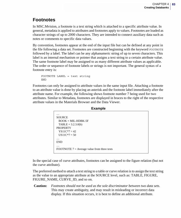
83CHAPTER 4Creating Databanks
FootnotesIn MSC.Mvision, a footnote is a text string which is attached to a specific attribute value. In general, metadata is applied to attributes and footnotes apply to values. Footnotes are loaded as character strings of up to 2000 characters. They are intended to connect auxiliary data such as notes or comments to specific data values.
By convention, footnotes appear at the end of the input file but can be defined at any point in the file following a data set. Footnotes are constructed beginning with the keyword FOOTNOTE followed by a label. The label can be any alphanumeric string of up to seven characters. This label is an internal mechanism or pointer that assigns a text string to a certain attribute value. The same footnote label may be assigned to as many different attribute values as applicable. The order or sequence of footnote labels or strings is not important. The general syntax of a footnote entry is:
FOOTNOTE LABEL = text stringEND
Footnotes can only be assigned to attribute values in the same input file. Attaching a footnote to an attribute value is done by placing an asterisk and the footnote label immediately after the attribute name. For example, the following shows footnote number 7 being used for two attributes. Similar to Metadata, footnotes are displayed in braces to the right of the respective attribute values in the Materials Browser and the Data Viewer.
Example
In the special case of curve attributes, footnotes can be assigned to the figure relation (but not the curve attribute).
The preferred method to attach a text string to a table or curve relation is to assign the text string as the value to an appropriate attribute at the SOURCE level, such as: TABLE, FIGURE, FIGURE_NAME, CURVE_ID, and so on.
Caution: Footnotes should not be used as the sole discriminator between two data sets. This may create ambiguity, and may result in misleading or incorrect data display. If this situation occurs, it is best to define an additional attribute.
…SOURCE
BOOK = MIL-HDBK-5FTABLE = 3.2.3.0(b)
PROPERTYYS11C*7 = 42US11C*7 = 50
…END…FOOTNOTE 7 = Average value from three tests
84
For example, consider the case of an extra test run to see the effect of humidity. In the databank there is an additional data row with the humidity set to a different value. Everything in the databank is the same except for the resultant property. Rather than trying to load the new value and explain it with a footnote, define an attribute called HUMIDITY at the SOURCE level or above and load the data as a separate branch of the data set. Add the nominal value of HUMIDITY to the other branches.
See Loading Figures section for more information on loading curve data.
Processing Input FilesThis section gives you information on how MSC.Mvision reads and loads the contents of an input file. In this section the organization and syntax of the input file and the rules for its use are described as well as information on how to add merge keys.
The process of adding data to a databank involves a number of steps. To understand the load process, it is helpful for you to understand the way data is stored in the databank.
Each relation in the databank is similar to a two-dimensional matrix (table row) or table using the following conventions:
• Each relation has rows and columns of data in a table-like structure
• A column represents an attribute in the relation
• A row contains the values from your input files
When data is being added to the databank, a significant amount of processing time is devoted to checking for identical rows in the databank. If the row being loaded matches an existing row for a given relation (and above) there is no additional row created. All information below the matching level of the hierarchy is appended to the existing row. By making sure that no two rows contain identical information, MSC.Mvision minimizes the size of the databank and the search time to locate data in the databank.
The system checks only the attributes found in the input file for each relation. If all the information being loaded for a specific relation in a data set does not match an existing row in the databank, then a row is added. The relations for the matching entry in the databank may have other attributes that are already defined. The new entry inherits these attributes and values when added to the databank.
Note: MSC.Mvision does not support multiple footnotes attached to a value and will be detected as an error on loading.
85CHAPTER 4Creating Databanks
Matching for Loading via Input FilesWhen an input file is read (data is loaded) the system searches the data which is already contained in the databank in order to “match” existing datarows. When loading data from an input file the system creates a dynamic instance of the databank which includes all existing data and the data being read, therefore all the data that precedes a specific set of input data is considered to be already contained in the databank.
Actually what the system is searching for when “matching” is “differences” between the specific hierarchy data set being currently input via the input file and the data already contained in the hierarchy relations of the existing datarows (materials).
The method by which this search for matching hierarchy data is performed is that when the hierarchy input data is read the system issues a query to determine a match (a true or positive return from the query), if a match is found the system issues the next query for the next relation in the input file and continues this process sequentially until the hierarchy data is exhausted or a “difference” (a false or negative return from the query) is encountered, at which time the system will ADD the data set from the input file. The query being issued by the system is an accumulative query, in that the query issued for a level 3 relation will include the queries for the previous level 1 and level 2 relations. If a new relation name is read from the input file the system truncates the query string at the level of the stated relation and restarts the string. When a property set is encountered in the input file the property set(s) are attached to the current hierarchy datarow sequentially until the next hierarchy name is encountered in the input file at which time the system begins to re-initiate system queries to reestablish the active hierarchy.
For the example shown below the first input invoked a query for:
_level_1.att_1a = a and _level.att_1b = b and _level_2.att_2a = a and _level_2.att_2b = b and _level.att_3a = a and _level.att_3c = c
This did not find a match (the query was false) and the system ADDED the new data for level_3, source and prop_1
The second input invoked a query for;
_level_1.att_1a = a and _level.att_1b = b and _level_2.att_2a = a and _level_2.att_2b = b and _level.att_3b = b
This matched (the query was true) and the system attached the new data to the existing hierarchy and assumed the attributes of the existing relation which it matched.
If the system finds a “difference” in the hierarchy it will add the new data (the data specified in the input file) beginning at the relation in which it found the “difference” and will attach to (inherit) ALL of the data contained in the relations above the relation in which it found a difference. If the hierarchy specified in an input file “matches” the existing hierarchy data as
Note: Adding the att_3c = c in this input creates a new row in the level_3 relation because the query was false and that in the second input the query was true and the att_3b = b was merged with the existing level_3 datarow (which did not create a new row in the level 3 relation) and the subsequent input data attached to it.
86
in the “second” input shown above, it will assume the values of all the attributes in the relation with which it matches. If a difference is found as in the “first” input shown a new row will be created in the level at which it found the difference.
For example if the databank is composed of the following:
level_1att_1a = a att_1b = b
level_2 att_2a = a att_2b = b
level_3 att_3a = a att_3b = b
source att_s = 1
prop_1 att_e = e
Inputting the following:
level_3 att_3a = a att_3c = c
source att_s = 1
prop_1 att_e = e
Will result in two hierarchy rows; one with a and b, the other with a and c when inputting the following:
level_3 att_3b = b
source att_s = 1
prop_1 att_e = e
Will result in two hierarchy rows; the new row will combine with the a and b row which already exists
There are some other important characteristics of loading data via an input that should be noted:
Once a hierarchy relation is stated in an input file that hierarchy relation is persistent (is part of the system query string and will be included in the data being added) until that hierarchy level or a higher level is restated in the input file. Restating a hierarchy level cancels all lower hierarchy levels and truncates the system query string. Restating a hierarchy level does NOT cancel the current source relation, all subsequent data that is added will include the last source data which was stated in the input file.
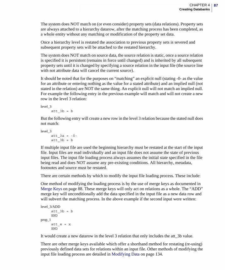
87CHAPTER 4Creating Databanks
The system does NOT match on (or even consider) property sets (data relations). Property sets are always attached to a hierarchy datarow, after the matching process has been completed, as a whole entity without any matching or modification of the property set data.
Once a hierarchy level is restated the association to previous property sets is severed and subsequent property sets will be attached to the restated hierarchy.
The system does NOT match on source data, the source relation is static, once a source relation is specified it is persistent (remains in force until changed) and is inherited by all subsequent property sets until it is changed by specifying a source relation in the input file (the source line with not attribute data will cancel the current source).
It should be noted that for the purposes on “matching” an explicit null (stating -0- as the value for an attribute or entering nothing as the value for a stated attribute) and an implied null (not stated in the relation) are NOT the same thing. An explicit null will not match an implied null. For example the following entry in the previous example will match and will not create a new row in the level 3 relation:
level_3 att_3b = b
But the following entry will create a new row in the level 3 relation because the stated null does not match:
level_3 att_3a = -0- att_3b = b
If multiple input file are used the beginning hierarchy must be restated at the start of the input file. Input files are read individually and an input file does not assume the state of previous input files. The input file loading process always assumes the initial state specified in the file being read and does NOT assume any pre-existing conditions. All hierarchy, metadata, footnotes and source must be restated.
There are certain methods by which to modify the input file loading process. These include:
One method of modifying the loading process is by the use of merge keys as documented in Merge Keys on page 88. These merge keys will only act on relations as a whole. The “ADD” merge key will unconditionally add the data specified in the input file as a new data row and will subvert the matching process. In the above example if the second input were written:
level_3/ADD att_3b = b END
prop_1 att_e = x END
It would create a new datarow in the level 3 relation that only includes the att_3b value.
There are other merge keys available which offer a shorthand method for restating (re-using) previously defined data sets for relations within an input file. Other methods of modifying the input file loading process are detailed in Modifying Data on page 134.
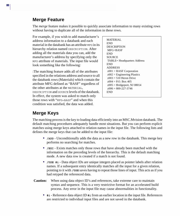
88
Merge FeatureThe merge feature makes it possible to quickly associate information to many existing rows without having to duplicate all of the information in these rows.
For example, if you wish to add manufacturer’s address information to a databank and each material in the databank has an attribute MFG in its hierarchy relation named DESCRIPTION. After adding all the materials data you can, add the manufacturer’s address by specifying only the MFG attribute of materials. The input file would look something like the following:
:The matching feature adds all of the attributes specified in the relations address and source to all the databank rows (Materials) which contain the attribute MFG defined as “BASF” regardless of the other attributes at the MATERIAL, DESCRIPTION and SOURCE levels of the databank. In effect, the system was asked to match only those rows with “MFG=BASF” and when this condition was satisfied, the data was added.
Merge KeysThe matching process is the key to loading data efficiently into an MSC.Mvision databank. The default matching procedures adequately handle most situations. But you can perform explicit matches using merge keys attached to relation names in the input file. The following lists and defines the merge keys that can be added to the input file:
• /ADD - Unconditionally adds the data as a new row in the databank. This merge key performs no searching for matches.
• /EXI - Exists matches only those rows that have already been matched with the information on the preceding levels of the hierarchy. This is the default matching mode. A new data row is created if a match is not found.
• /USE #i - Data object IDs are unique integers placed as pointer labels after relation names. If a subsequent entry identically matches all the input for a given relation, pointing to it with /USE saves having to repeat those lines of input. This acts as if you had retyped the referenced data.
Caution: When using data object ID’s and references, take extreme care to maintain syntax and sequence. This is a very restrictive format for an accelerated build process. Any error in the input file may cause abnormalities in functionality.
• #i - Reference data object ID #i from an earlier location in the input file. References are restricted to individual input files and are not saved in the databank.
MATERIALENDDESCRIPTION MFG=BASFENDSOURCE TABLE= Headquarters AddressENDADDRESS z001 = BASF Corporation z002 = Engineering Plastics z003 = 510 Heron Drive z004 = P.O. Box 405 z005 = Bridgeport, NJ 08014 z006 = 800-227-3746END
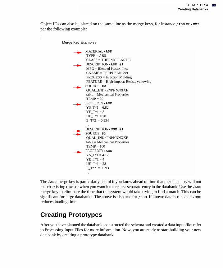
89CHAPTER 4Creating Databanks
Object IDs can also be placed on the same line as the merge keys, for instance /ADD or /EXI per the following example:
:
The /ADD merge key is particularly useful if you know ahead of time that the data entry will not match existing rows or when you want it to create a separate entry in the databank. Use the /ADD merge key to eliminate the time that the system would take trying to find a match. This can be significant for large databanks. The above is also true for /USE. If known data is repeated /USE reduces loading time.
Creating PrototypesAfter you have planned the databank, constructed the schema and created a data input file: refer to Processing Input Files for more information. Now, you are ready to start building your new databank by creating a prototype databank.
MATERIAL/ADD TYPE = ABS CLASS = THERMOPLASTICDESCRIPTION/ADD #1 MFG = Blended Plastix, Inc. CNAME = TERPUSAN 799 PROCESS = Injection Molding FEATURE = High-impact; Resists yellowingSOURCE #2 QUAL_IND=PNPNNNXXF table = Mechanical PropertiesTEMP = 20
PROPERTY/ADD YS_T*1 = 6.82 YE_T*1 = 3 UE_T*1 = 20 E_T*2 = 0.334…DESCRIPTION/USE #1SOURCE #3QUAL_IND=PNPNNNXXF
table = Mechanical PropertiesTEMP = 100
PROPERTY/ADD YS_T*1 = 4.12 YE_T*1 = 4 UE_T*1 = 28 E_T*2 = 0.293…
Merge Key Examples
90
Create a test or prototype databank using at least one value for each attribute in the databank. Include an example data set from each source and for each user and user group. For example, if you are including curves in your databank, you should include curves in the prototype to verify that everything works correctly.
The prototype databank will help you validate or facilitate the following:
• Goal verification
• Design changes
• Content additions and revisions
Complete the following steps to create a prototype:
1. Plan the Databank. (See Chapter 2.)
2. Design the Databank. (See Chapter 3.)
3. Initialize the databank. (See this chapter.)
4. Create the prototype input file. (See this chapter.)
5. Load the data. (See this chapter.)
6. Save the databank. (See this chapter.)
This prototype databank can be used to verify whether or not your databank will work. Give the prototype to a primary user in each of your user groups to review. Get feedback from these users as soon as possible after it has been made available. You may find that opinions change significantly when users actually see and work with a sample databank.
After your prototype databank has been reviewed:
7. Evaluate the results.
8. Make any necessary revisions or changes to the schema and data and create another prototype for further review by the users.
9. Repeat the above steps until you think it is right!
After the prototype databank has been approved:
10. Load all the data.
Data Loading MethodsMSC.Mvision provides various approaches and techniques for loading data. All involve the same basic steps and have two essential components: the schema and the data.
The following are the various methods of loading data into an MSC.Mvision databank:
1. Interactive Builder
Note: It is highly recommended that you create a prototype before loading data into a databank. See Creating Prototypes on page 89.
91CHAPTER 4Creating Databanks
2. Command Line Builder
3. Spreadsheet (PUT Command)
4. Session Files
5. Database Programmatic Interface (DPI)
6. EXPRESS Utilities
Each method accomplishes the same function. It takes data in one format and assembles it into a common structure for access by the MSC.Mvision system. The resulting data structure is equivalent, regardless of the method used. Each method has distinct advantages and disadvantages which are discussed in the following sections.
Input files and loading procedures are dependent on the structure of the databank for which they are intended. After the prototype databank is approved, it is best to not change the schema. If you do, it could mean extensive changes to the content and organization of the data in the existing input files.
The Interactive Builder and Command Line Builder uses the MSC.Mvision input file format described in this section to load data into an initialized databank. These input file can also be used by session files and the DPI loading functions.
Interactive BuilderIn this section we describe the use of the MSC.Mvision input file in conjunction with the interactive Builder interface.
The following step-by-step process explains how to add data to an existing databank via an input file. These same functions are performed as part of creating a new databank and correspond to the menu selections File - Builder Functions - New Databank… and File - Builder Functions - Read Data….
1. Access MSC.Mvision Builder.
2. Open the target databank from the File - Open Databank… menu.
Note: Before loading data, MSC.Mvision scans the define and input files for errors. These errors and warnings are reported interactively and in a log file. You should note all warnings and correct all errors before the databank can be successfully loaded.
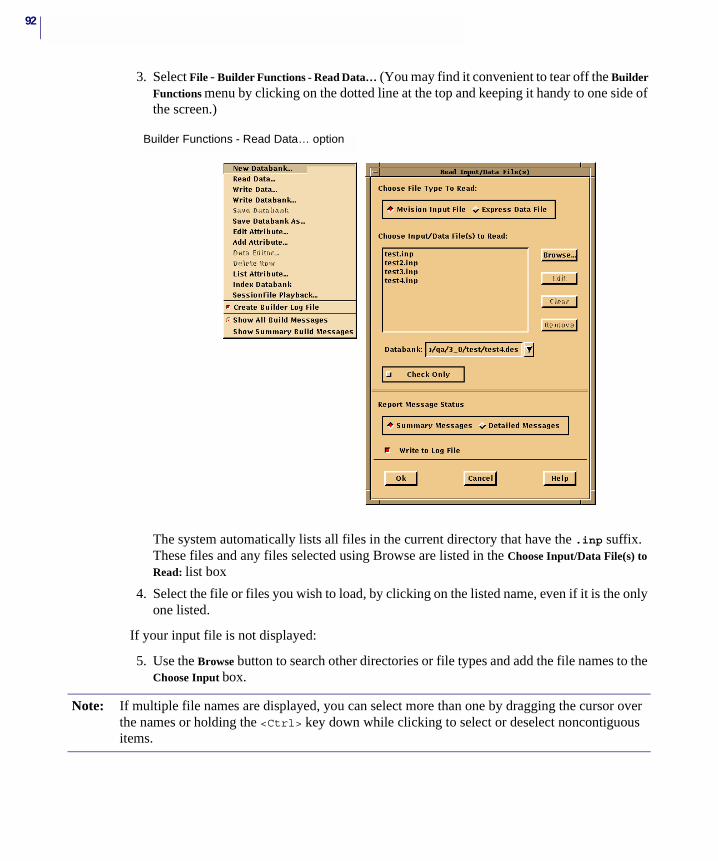
92
3. Select File - Builder Functions - Read Data… (You may find it convenient to tear off the Builder Functions menu by clicking on the dotted line at the top and keeping it handy to one side of the screen.)
The system automatically lists all files in the current directory that have the .inp suffix. These files and any files selected using Browse are listed in the Choose Input/Data File(s) to Read: list box
4. Select the file or files you wish to load, by clicking on the listed name, even if it is the only one listed.
If your input file is not displayed:
5. Use the Browse button to search other directories or file types and add the file names to the Choose Input box.
Builder Functions - Read Data… option
Note: If multiple file names are displayed, you can select more than one by dragging the cursor over the names or holding the <Ctrl> key down while clicking to select or deselect noncontiguous items.
93CHAPTER 4Creating Databanks
The file processing order is determined either by the file selection order in the Browse window, which designates the order in which files are executed (regardless of where they appear in the list), or if the input file listing is cleared and the file names reselected (clicked on), the files will be executed in the order in which they are listed regardless of the selection order. The listed order is always alphabetical.
Use the buttons to the right of the Choose Input File listing to perform the following functions:
Edit allows you to open a selected file and edit it via your local editor.
Clear deselects selected items.
Remove deletes selected file names from the Choose Input box.
6. The Databank box displays the databank item into which the new data will be loaded.
Click the triangle button to the right of the cell to select a different target databank. The choices include only databanks which are open in the current session.
7. Toggle the Check Only button on if you want to check the input file(s) for errors without loading the data. This step is recommended if this is the first time the input file is used.
8. The Report Message Status section controls the display of diagnostic messages generated by the load module. Messages include information, warning, and error messages. Summary messages include only warnings and error messages.
9. Select Summary Messages and Write to Log File.
A slightly condensed version of the messages are displayed in the Status window. Writing a log file is recommended because it is usually convenient to scan the log file for problems, particularly if the input file is very long. The name of the log file will be builder.log.h, where his the version number of the file.
10. Select the Ok button when you are ready to begin the loading (or input file checking) process.
When the load process is complete, an Information window is displayed, showing the number of Information, Warning, and Error messages, respectively.
You can examine these messages in the Status window or the latest version of the log file. If there are no Error messages, the Read Data window closes and the Materials Browser displays the databank in its newly-modified state.
If there are errors or warnings, you can edit the input file directly from the Read Input/Data File(s) window by selecting Edit, saving it and reloading the input file.
Note: You can set the default selections in the Read Data… window by modifying the Application Resource file. For more information, refer to Appendix A of the MSC.Mvision Builder and Evaluator User’s Guide and Reference.
Note: If the input file contains an error, the build will be inhibited. No data is loaded and the system displays a window that reports the failure to load data. All errors must be corrected before the system will load the databank.
94
11. If there are errors you don’t understand, execute the input file with Detailed Messages set and review the messages in the status window and log file.
Detailed Messages provides information about the actual data loading. It also returns specific messages about each relation and attribute being added, matched, and so on, which can be very useful in locating the point in the input file where the problem originated. The messages report each relation examined during the load and the action taken, stating that the data for a relation was either added or matched. Adding creates a new entry in the databank for the given relation and matching indicates that the information in the input file was the same as the data in an existing relation in the databank.
If any of the diagnostic messages are classified as errors, the resulting databank is suspect and you must correct the error and reload. If your databank is large, you can break the data into multiple input files. That way you can save the databank after each file loads successfully and not have to reload that portion if you encounter problems later. See Diagnostic Messages on page 100 for more information.
12. Repeat the process of error correction and reloading as necessary until you are satisfied with the result.
13. Save the databank. For more details see the Saving Databanks section at the end of this chapter.
Command Line BuilderThe Command Line Builder is provided to facilitate the building of large scale databanks or for databanks that require routine or periodic updates. You can execute these programs using commands in a UNIX shell window or a Windows command prompt. Theses programs are designed to provide more experienced users with the capability to build databanks from shell scripts, batch files, or from MSC.Mvision session files. Collectively these tools are called the Batch Builder Programs.
To load data into databanks using the Command Line Builder, enter the commands and arguments on the command line. All of the Builder Functions in MSC.Mvision can be accessed using these commands.
For information on these programs, refer to Appendix B - Batch Builder Programs on page 175 where each program and its commands with options are described in detail.
Spreadsheet Using the MSC.Mvision Spreadsheet, you can process raw data and convert it to a form for input into an MSC.Mvision databank. The Spreadsheet is a useful tool for reading raw test data and processing it into a desired form before placing it in an MSC.Mvision databank. This method is especially convenient when there is a lot of test data in a consistent format. Be aware that the Spreadsheet process lacks the control and error checking capabilities of the input file process and provides less feedback on the load process.
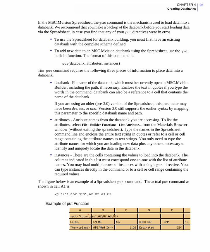
95CHAPTER 4Creating Databanks
In the MSC.Mvision Spreadsheet, the put command is the mechanism used to load data into a databank. We recommend that you make a backup of the databank before you start loading data via the Spreadsheet, in case you find that any of your put directives were in error.
• To use the Spreadsheet for databank building, you must first have an existing databank with the complete schema defined
• To add new data to an MSC.Mvision databank using the Spreadsheet, use the put built-in function. The format of this command is:
put(databank, attributes, instances)
The put command requires the following three pieces of information to place data into a databank.
• databank - Filename of the databank, which must be currently open in MSC.Mvision Builder, including the path, if necessary. Enclose the text in quotes if you type the words in the command. databank can also be a reference to a cell that contains the name of the databank.
If you are using an older (pre-3.0) version of the Spreadsheet, this parameter may have been des, tes, or ana. Version 3.0 still supports the earlier syntax by mapping this parameter to the specific databank name and path.
• attributes - Attribute names from the databank you are accessing. To list the attributes, select File - Builder Functions - List Attribute... from the Materials Browser window (without exiting the spreadsheet). Type the names in the Spreadsheet command line and enclose the entire text string in quotes or refer to a cell or cell range containing the attribute names as text strings. You only need to type the attribute names for which you are loading new data plus any others necessary to identify and uniquely locate the data in the databank.
• instances - These are the cells containing the values to load into the databank. The columns indicated in this list must correspond one-to-one with the list of attribute names. You may load multiple rows of instances with a single put directive. You can type instances directly in the command or to a cell or cell range containing the required values.
The figure below is an example of a Spreadsheet put command. The actual put command as shown in cell A1 is:
=put(“tutor.des”,A2:G2,A3:G3)
Example of put Function
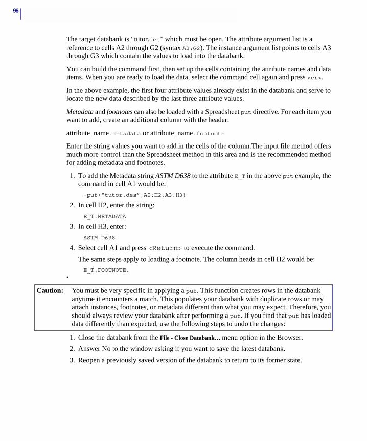
96
The target databank is “tutor.des” which must be open. The attribute argument list is a reference to cells A2 through G2 (syntax A2:G2). The instance argument list points to cells A3 through G3 which contain the values to load into the databank.
You can build the command first, then set up the cells containing the attribute names and data items. When you are ready to load the data, select the command cell again and press <cr>.
In the above example, the first four attribute values already exist in the databank and serve to locate the new data described by the last three attribute values.
Metadata and footnotes can also be loaded with a Spreadsheet put directive. For each item you want to add, create an additional column with the header:
attribute_name.metadata or attribute_name.footnote
Enter the string values you want to add in the cells of the column.The input file method offers much more control than the Spreadsheet method in this area and is the recommended method for adding metadata and footnotes.
1. To add the Metadata string ASTM D638 to the attribute E_T in the above put example, the command in cell A1 would be:
=put(“tutor.des”,A2:H2,A3:H3)
2. In cell H2, enter the string:
E_T.METADATA
3. In cell H3, enter:
ASTM D638
4. Select cell A1 and press <Return> to execute the command.
The same steps apply to loading a footnote. The column heads in cell H2 would be:
E_T.FOOTNOTE. •
1. Close the databank from the File - Close Databank… menu option in the Browser.
2. Answer No to the window asking if you want to save the latest databank.
3. Reopen a previously saved version of the databank to return to its former state.
Caution: You must be very specific in applying a put. This function creates rows in the databank anytime it encounters a match. This populates your databank with duplicate rows or may attach instances, footnotes, or metadata different than what you may expect. Therefore, you should always review your databank after performing a put. If you find that put has loaded data differently than expected, use the following steps to undo the changes:
97CHAPTER 4Creating Databanks
4. Save your data frequently using the Spreadsheet - Save Databank or Builder Functions - Save Databank or Save Databank As… option. This ensures that the data is loaded as you planned and any errors can be removed before additional data is loaded.
For more information on using the Spreadsheet and its functions, refer to the MSC.Mvision Builder and Evaluator User’s Guide and Reference.
Session Files The session file is a valuable tool for automating databank building. Session files containing all the spreadsheet and build commands executed during a session are created each time you run MSC.Mvision. The commands are written in PCL (PATRAN Command Language) format in the text file builder.ses.n.
To produce a session file that creates a new databank and loads all the input files:
1. Run MSC.Mvision Builder, perform the sequence of steps for creating and loading the databank and exit MSC.Mvision.
The latest version of the builder.ses.n file is a record of the actions performed in the previous steps. You may want to rename the file to identify it and prevent overwriting it in the future. Review the file and edit filenames and/or commands as required.
2. To produce a new version of the databank, rename the original version of the databank and run the session file as described below.
3. Restart MSC.Mvision Builder.
4. Select File - Builder Functions - Session File Playback… and select the appropriate session file.
5. Click the triangle button or use the Browse… feature to navigate to the correct filename.
6. You can click the Edit button to bring up the selected session file in a text editor and modify it as needed.
Even if you are not an expert in PCL, session files can be useful tools with a minimum of editing. The majority of commands in a session file are intuitive, but the exacting syntax must be maintained. Many common, but useful editing changes are obvious, such as changing a file name in a statement, for example:
MvReadDefineFile( “test1.des”, “test1.def” )
Most session files refer to file names and paths that the referenced file must be in. The specified location or the file name must be changed for the session file to function properly.
The following is an example of a session file for creating and loading a databank:
Note: A put cell executes the put whenever you press <Return> from that cell. This occurs when you complete typing the put formula for the first time and press <Return> if the cells referred to in the command are already populated. You should be very careful about your actions when working on a put, as it is easy to inadvertently load data into a databank.
Caution: Do not put a row of data that has a empty cell in a column corresponding to a curve attribute. This will corrupt the databank.
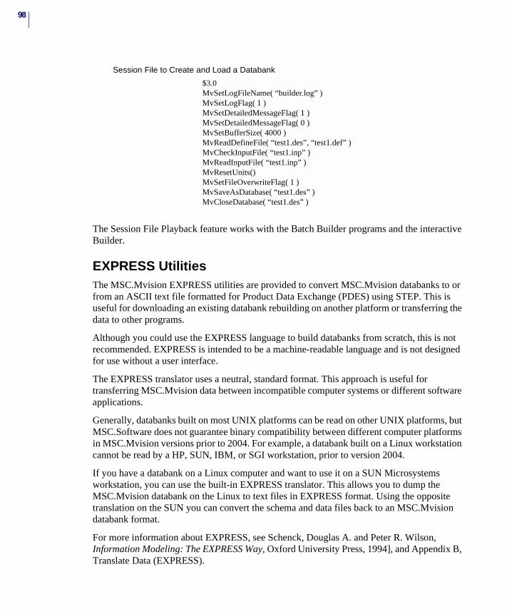
98
The Session File Playback feature works with the Batch Builder programs and the interactive Builder.
EXPRESS UtilitiesThe MSC.Mvision EXPRESS utilities are provided to convert MSC.Mvision databanks to or from an ASCII text file formatted for Product Data Exchange (PDES) using STEP. This is useful for downloading an existing databank rebuilding on another platform or transferring the data to other programs.
Although you could use the EXPRESS language to build databanks from scratch, this is not recommended. EXPRESS is intended to be a machine-readable language and is not designed for use without a user interface.
The EXPRESS translator uses a neutral, standard format. This approach is useful for transferring MSC.Mvision data between incompatible computer systems or different software applications.
Generally, databanks built on most UNIX platforms can be read on other UNIX platforms, but MSC.Software does not guarantee binary compatibility between different computer platforms in MSC.Mvision versions prior to 2004. For example, a databank built on a Linux workstation cannot be read by a HP, SUN, IBM, or SGI workstation, prior to version 2004.
If you have a databank on a Linux computer and want to use it on a SUN Microsystems workstation, you can use the built-in EXPRESS translator. This allows you to dump the MSC.Mvision databank on the Linux to text files in EXPRESS format. Using the opposite translation on the SUN you can convert the schema and data files back to an MSC.Mvision databank format.
For more information about EXPRESS, see Schenck, Douglas A. and Peter R. Wilson, Information Modeling: The EXPRESS Way, Oxford University Press, 1994], and Appendix B, Translate Data (EXPRESS).
Session File to Create and Load a Databank
$3.0MvSetLogFileName( “builder.log” )MvSetLogFlag( 1 )MvSetDetailedMessageFlag( 1 )MvSetDetailedMessageFlag( 0 )MvSetBufferSize( 4000 )MvReadDefineFile( “test1.des”, “test1.def” )MvCheckInputFile( “test1.inp” )MvReadInputFile( “test1.inp” )MvResetUnits()MvSetFileOverwriteFlag( 1 )MvSaveAsDatabase( “test1.des” )MvCloseDatabase( “test1.des” )
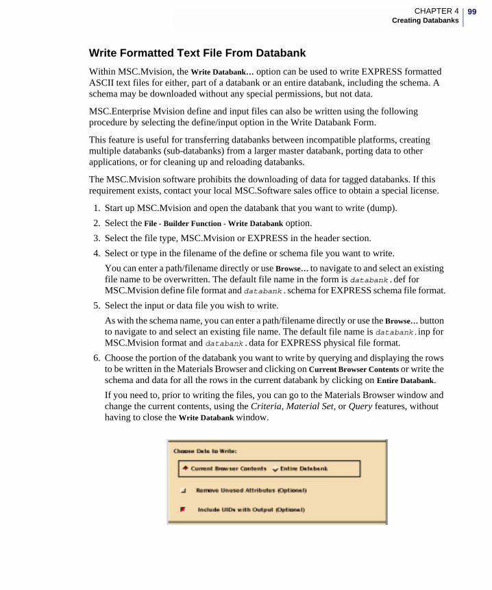
99CHAPTER 4Creating Databanks
Write Formatted Text File From Databank
Within MSC.Mvision, the Write Databank… option can be used to write EXPRESS formatted ASCII text files for either, part of a databank or an entire databank, including the schema. A schema may be downloaded without any special permissions, but not data.
MSC.Enterprise Mvision define and input files can also be written using the following procedure by selecting the define/input option in the Write Databank Form.
This feature is useful for transferring databanks between incompatible platforms, creating multiple databanks (sub-databanks) from a larger master databank, porting data to other applications, or for cleaning up and reloading databanks.
The MSC.Mvision software prohibits the downloading of data for tagged databanks. If this requirement exists, contact your local MSC.Software sales office to obtain a special license.
1. Start up MSC.Mvision and open the databank that you want to write (dump).
2. Select the File - Builder Function - Write Databank option.
3. Select the file type, MSC.Mvision or EXPRESS in the header section.
4. Select or type in the filename of the define or schema file you want to write.
You can enter a path/filename directly or use Browse… to navigate to and select an existing file name to be overwritten. The default file name in the form is databank.def for MSC.Mvision define file format and databank.schema for EXPRESS schema file format.
5. Select the input or data file you wish to write.
As with the schema name, you can enter a path/filename directly or use the Browse… button to navigate to and select an existing file name. The default file name is databank.inp for MSC.Mvision format and databank.data for EXPRESS physical file format.
6. Choose the portion of the databank you want to write by querying and displaying the rows to be written in the Materials Browser and clicking on Current Browser Contents or write the schema and data for all the rows in the current databank by clicking on Entire Databank.
If you need to, prior to writing the files, you can go to the Materials Browser window and change the current contents, using the Criteria, Material Set, or Query features, without having to close the Write Databank window.
100
7. Select Remove Unused Attributes if you are writing a define or schema file to use for creating a new databank.
This option excludes from the define or schema file being written any attributes for which there is no data in the current Browser contents. It also removes the associated pointers in an EXPRESS data file. Usually you do not want to activate this option in order to maintain the integrity of the schema even if you are only writing a portion of the databank. Empty attributes and attributes with no assigned values are never written to input or data files.
8. Select whether the ‘unique identifiers’ (UID) for the data are to be written to the input file or the EXPRESS schema and data files. The UID can be used in reloading the databank to maintain the exact data structure. However, the UID’s should not be included if you are recreating a new databank or changing the data structure.
9. To write a part of a databank, write the define or schema file with the Entire Databank option set, even though you may be writing only a small portion of the data. This means you will execute the Write Databank option twice. Once with Define/Schema, Entire Databank set and once with Input/Schema, Current Browser Contents.
10. Select the Report Message Status you require and click Ok to execute the write process. The specified files are written to the form.
If your reason for writing the databank files was to make changes and then reload, the next logical step is to edit the text files and rebuild or reload all or part of the databank. If you have created EXPESS formatted schema and data files, you can build an MSC.Mvision databank by selecting the EXPRESS options in the New Databank or Read Data forms. Building from EXPRESS formatted files is very fast because the EXPRESS model is an exact definition of the databank and there is a minimum of checking performed.
Database Programmatic Interface (DPI)When using the Database Programmatic Interface (DPI), MSC.Mvision provides a library of C routines for accessing MSC.Mvision Database Functions. DPI functions can be incorporated into user-written programs for accessing and building MSC.Mvision databanks. MSC.Mvision also makes available PCL-wrapped DPI functions that can be incorporated into user-written code or used in scripts readable via session files. Refer to Appendix B - Batch Builder Programs on page 175.
Diagnostic MessagesIn most cases, it may be easier to perform the MSC.Mvision - EXPRESS conversion using the Batch Builder program capabilities. See Appendix B for more information.
Caution: If you are building a databank in steps and you write out part of it to clean up the input data or schema, check the output text file names. To avoid overwriting the original input, change the names in the form if required.
101CHAPTER 4Creating Databanks
Activating the File - Builder Functions - Create Log File option causes all diagnostic messages produced during a Builder session operation to be saved in a log file. These include information, warning, and error messages. The default name of this file is builder.log.h, where h is a sequential run number.
A slightly condensed version of the diagnostic messages is always written to the status window during an MSC.Mvision session. If a schema or input file is extensive or the loading processing is complicated, we recommend that you save the diagnostics in the log file. This allows you to search and review the messages after processing.
1. Select Write to Log File in the individual Builder Functions forms or from the Builder Functions menu.
To control the extent and amount of information in the log file:
2. Select either Detailed Messages or Summary Messages.
Setting the message mode does not effect the messages returned from any non-build operation in the interactive interface. The system always returns error messages regardless of the setting.
Detailed Messages
Detailed Messages sets the system to a detailed listing of diagnostic messages for Build operations. This listing includes information, warning, and error messages. The messages are written to the Status Window. You can save the messages in a log file by using the procedure described in the previous section.
If there are errors you don’t understand:
Set Detailed Messages option on and rerun the process to get a complete listing of messages. The line numbers referred to in the messages can be helpful in tracing problems for the reloading process. These are the sequential line numbers of the define or input files. Most text editors display line numbers or at least allow you to specify a given line. In vi, for example, the command :set nu displays line numbers and :i moves the cursor to line number i.
The messages also include information about the relations and attributes being loaded such as match data which is matched and/or added. This can be very useful in determining where a problem originated.
When reviewing the messages for the loading process, add indicates that the system has created a new entry in the databank. Match indicates that the qualifying attributes were the same as a relation already in the databank, so that the part of the data that was the same was not repeated unnecessarily. The new data was included in the specified relation.
Summary Messages
The Summary Messages option sets the system to return a condensed listing of diagnostic messages for all Build operations. As with Detailed Messages option, the messages returned appear in the Status Window. You can save these messages in a log file using the procedure described in the previous section.
102
Select Summary Messages and Create Log File.
Loading TablesIn an MSC.Mvision databank Property tables are data relations that contain a set of attributes other than curves or images. This is typically where property values in the form of individual values are stored.
Sample Table from MIL-HDBK-5
The following segment of an input file is used to load a table from the MSC.Mvision MIL-HDBK-5 databank. It is a typical example of the format and syntax for loading a table. The table being loaded contains reduced property values for 250 Maraging Steel sheet.
These properties include:
• Ultimate Strength in Tension (US11T, US22T, US33T)
• Yield Strength in Tension (YS11T, YS22T, YS33T)
• Yield Strength in Compression (YS11C, YS22C)
• Ultimate Strength in Bearing (US15B, US20B)
• Yield Strength in Bearing (YS15B, YS20B)
• Ultimate Elongation (UE11T, UE22T, UE33T)
• Modulus of Elasticity in Tension (E11T)
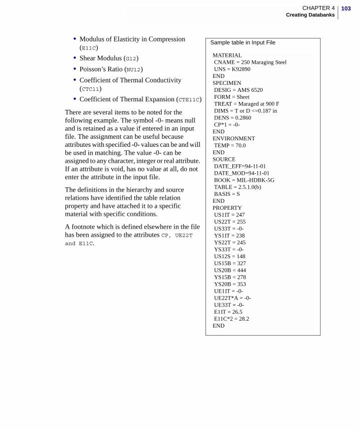
103CHAPTER 4Creating Databanks
• Modulus of Elasticity in Compression (E11C)
• Shear Modulus (G12)
• Poisson’s Ratio (NU12)
• Coefficient of Thermal Conductivity (CTC11)
• Coefficient of Thermal Expansion (CTE11C)
There are several items to be noted for the following example. The symbol -0- means null and is retained as a value if entered in an input file. The assignment can be useful because attributes with specified -0- values can be and will be used in matching. The value -0- can be assigned to any character, integer or real attribute. If an attribute is void, has no value at all, do not enter the attribute in the input file.
The definitions in the hierarchy and source relations have identified the table relation property and have attached it to a specific material with specific conditions.
A footnote which is defined elsewhere in the file has been assigned to the attributes CP, UE22T and E11C.
MATERIAL CNAME = 250 Maraging Steel UNS = K92890ENDSPECIMEN DESIG = AMS 6520 FORM = SheetTREAT = Maraged at 900 FDIMS = T or D <=0.187 in
DENS = 0.2860 CP*1 = -0-ENDENVIRONMENT TEMP = 70.0ENDSOURCE DATE_EFF=94-11-01 DATE_MOD=94-11-01 BOOK = MIL-HDBK-5G TABLE = 2.5.1.0(b)BASIS = S
ENDPROPERTY US11T = 247 US22T = 255 US33T = -0- YS11T = 238 YS22T = 245 YS33T = -0-US12S = 148
US15B = 327 US20B = 444 YS15B = 278 YS20B = 353 UE11T = -0- UE22T*A = -0- UE33T = -0- E11T = 26.5 E11C*2 = 28.2END
Sample table in Input File
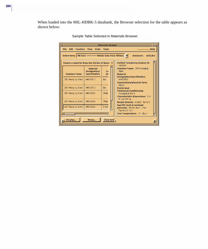
104
When loaded into the MIL-HDBK-5 databank, the Browser selection for the table appears as shown below:
Table shown in input file example
Sample Table Selected in Materials Browser
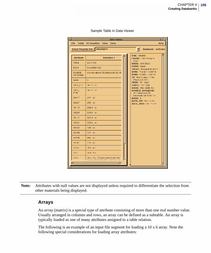
105CHAPTER 4Creating Databanks
Arrays
An array (matrix) is a special type of attribute consisting of more than one real number value. Usually arranged in columns and rows, an array can be defined as a subtable. An array is typically loaded as one of many attributes assigned to a table relation.
The following is an example of an input file segment for loading a 10 x 6 array. Note the following special considerations for loading array attributes:
Sample Table in Data Viewer
Note: Attributes with null values are not displayed unless required to differentiate the selection from other materials being displayed.
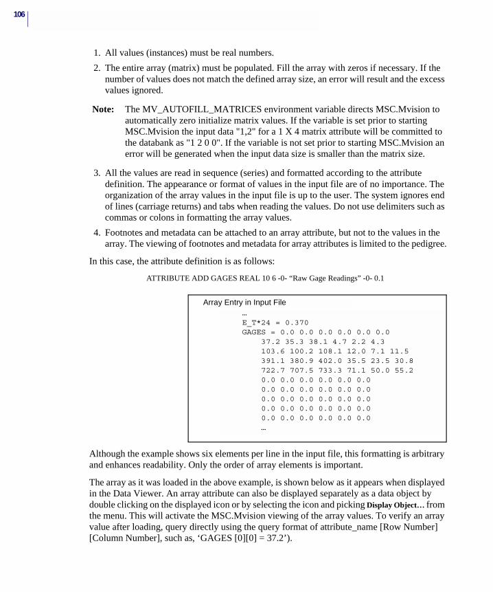
106
1. All values (instances) must be real numbers.
2. The entire array (matrix) must be populated. Fill the array with zeros if necessary. If the number of values does not match the defined array size, an error will result and the excess values ignored.
Note: The MV_AUTOFILL_MATRICES environment variable directs MSC.Mvision to automatically zero initialize matrix values. If the variable is set prior to starting MSC.Mvision the input data "1,2" for a 1 X 4 matrix attribute will be committed to the databank as "1 2 0 0". If the variable is not set prior to starting MSC.Mvision an error will be generated when the input data size is smaller than the matrix size.
3. All the values are read in sequence (series) and formatted according to the attribute definition. The appearance or format of values in the input file are of no importance. The organization of the array values in the input file is up to the user. The system ignores end of lines (carriage returns) and tabs when reading the values. Do not use delimiters such as commas or colons in formatting the array values.
4. Footnotes and metadata can be attached to an array attribute, but not to the values in the array. The viewing of footnotes and metadata for array attributes is limited to the pedigree.
In this case, the attribute definition is as follows:
ATTRIBUTE ADD GAGES REAL 10 6 -0- “Raw Gage Readings” -0- 0.1
Although the example shows six elements per line in the input file, this formatting is arbitrary and enhances readability. Only the order of array elements is important.
The array as it was loaded in the above example, is shown below as it appears when displayed in the Data Viewer. An array attribute can also be displayed separately as a data object by double clicking on the displayed icon or by selecting the icon and picking Display Object… from the menu. This will activate the MSC.Mvision viewing of the array values. To verify an array value after loading, query directly using the query format of attribute_name [Row Number] [Column Number], such as, ‘GAGES [0][0] = 37.2’).
Array Entry in Input File…E_T*24 = 0.370GAGES = 0.0 0.0 0.0 0.0 0.0 0.0
37.2 35.3 38.1 4.7 2.2 4.3103.6 100.2 108.1 12.0 7.1 11.5391.1 380.9 402.0 35.5 23.5 30.8722.7 707.5 733.3 71.1 50.0 55.20.0 0.0 0.0 0.0 0.0 0.00.0 0.0 0.0 0.0 0.0 0.00.0 0.0 0.0 0.0 0.0 0.00.0 0.0 0.0 0.0 0.0 0.00.0 0.0 0.0 0.0 0.0 0.0…
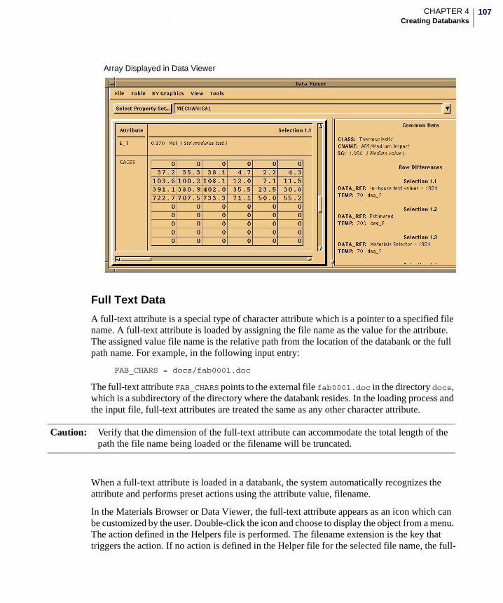
107CHAPTER 4Creating Databanks
Full Text Data
A full-text attribute is a special type of character attribute which is a pointer to a specified file name. A full-text attribute is loaded by assigning the file name as the value for the attribute. The assigned value file name is the relative path from the location of the databank or the full path name. For example, in the following input entry:
FAB_CHARS = docs/fab0001.doc
The full-text attribute FAB_CHARS points to the external file fab0001.doc in the directory docs, which is a subdirectory of the directory where the databank resides. In the loading process and the input file, full-text attributes are treated the same as any other character attribute.
When a full-text attribute is loaded in a databank, the system automatically recognizes the attribute and performs preset actions using the attribute value, filename.
In the Materials Browser or Data Viewer, the full-text attribute appears as an icon which can be customized by the user. Double-click the icon and choose to display the object from a menu. The action defined in the Helpers file is performed. The filename extension is the key that triggers the action. If no action is defined in the Helper file for the selected file name, the full-
Array Displayed in Data Viewer
Caution: Verify that the dimension of the full-text attribute can accommodate the total length of the path the file name being loaded or the filename will be truncated.
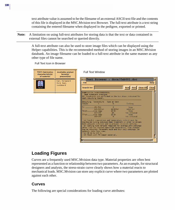
108
text attribute value is assumed to be the filename of an external ASCII text file and the contents of this file is displayed in the MSC.Mvision text Browser. The full-text attribute is a text string containing the entered filename when displayed in the pedigree, exported or printed.
A full-text attribute can also be used to store image files which can be displayed using the Helper capabilities. This is the recommended method of storing images in an MSC.Mvision databank. An image filename can be loaded to a full-text attribute in the same manner as any other type of file name.
Loading FiguresCurves are a frequently used MSC.Mvision data type. Material properties are often best represented as a function or relationship between two parameters. As an example, for structural designers and analysts, the stress-strain curve clearly shows how a material reacts to mechanical loads. MSC.Mvision can store any explicit curve where two parameters are plotted against each other.
Curves
The following are special considerations for loading curve attributes:
Note: A limitation on using full-text attributes for storing data is that the text or data contained in external files cannot be searched or queried directly.
Full Text Icon in Browser
Text Browser : docs/fab001.doc
Full Text Window
109CHAPTER 4Creating Databanks
1. A curve attribute must have the same name as the curve relation and both names must contain the string “vs”.
2. All values (instances) loaded for a curve attribute are compiled into one continuous curve. This curve may have several segments.
3. All values (instances) loaded are read sequentially as X-value, Y-value, plot code. End-of-line, carriage returns, and tabs are ignored.
4. The input value set must always be terminated with an END statement.
If you are loading a curve from a spreadsheet, you must first construct it as a polyline. A curve attribute in MSC.Mvision is a special type of figure attribute with special characteristics. A curve attribute is loaded in the same general manner as an array attribute. Only the curve data XY coordinates and plot codes are loaded by the input file process. Curve title and axis labels are a characteristic of the attribute which is defined in the databank.
Note that in writing an input file to load a curve attribute, there is no limit to the total number of characters per line and commas are not required to indicate a line continuation. There is also no limit to the number of points which can be entered per curve as stated above. All values are read in sequentially as the arrangement of the values in the input file are of no importance. What is important is that the entered values sequentially match the characteristics of the attribute. This means that the first value read will match the second half of the name (X value) and the second value read will match the first part of the name (Y value). The third value is the plot code This format is repeated to the end of data. For readability, curve data is usually arranged as shown in the example.
The following example of input data and the corresponding plotted curve is a stress-strain curve for 6061-T6 Aluminum Alloy die forgings from the MSC.Mvision MIL-HDBK-5 databank. Only the source and figure relation data are shown; the complete input file also contains the pedigree (hierarchy) data, and footnote definition.
The curve attribute and figure relation definitions in the define file which correspond to the example are as follows:
ATT ADD CTC11vsTEMP REAL 3 0 “deg_F; Btu/hr-ft-deg_F”,“Temperature; Coefficient of Thermal Conductivity”
RELATION ADD CTC11vsTEMP CTC11vsTEMP
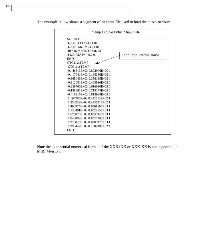
110
The example below shows a segment of an input file used to load the curve attribute.
Note the exponential numerical format of the XXX+XX or XXX-XX is not supported in MSC.Mvision.
SOURCE DATE_EFF=94-11-01 DATE_MOD=94-11-01 BOOK = MIL-HDBK-5G FIGURE*1= 3.6.2.0ENDCTC11vsTEMP CTC11vsTEMP=-0.446613E+03 0.802046E+00 1-0.417941E+03 0.185336E+02 1-0.365946E+03 0.356135E+02 1-0.312051E+03 0.493530E+02 1-0.239760E+03 0.616020E+02 1-0.158991E+03 0.715178E+02 1-0.416316E+02 0.812928E+02 1 0.105785E+03 0.892513E+02 1 0.253332E+03 0.953721E+02 1 0.400974E+03 0.100156E+03 1 0.530481E+03 0.102755E+03 1 0.675070E+03 0.103694E+03 1 0.843089E+03 0.102478E+03 1 0.923026E+03 0.100697E+03 1 0.996442E+03 0.970738E+02 4END
Sample Curve Entry in Input File
Note the curve name
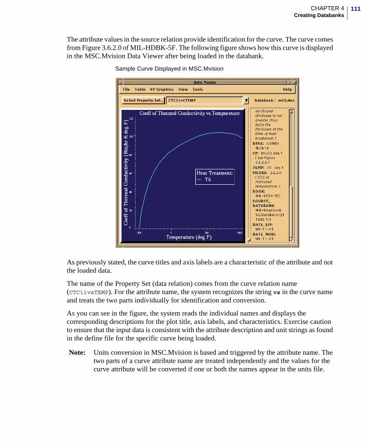
111CHAPTER 4Creating Databanks
The attribute values in the source relation provide identification for the curve. The curve comes from Figure 3.6.2.0 of MIL-HDBK-5F. The following figure shows how this curve is displayed in the MSC.Mvision Data Viewer after being loaded in the databank.
As previously stated, the curve titles and axis labels are a characteristic of the attribute and not the loaded data.
The name of the Property Set (data relation) comes from the curve relation name (CTC11vsTEMP). For the attribute name, the system recognizes the string vs in the curve name and treats the two parts individually for identification and conversion.
As you can see in the figure, the system reads the individual names and displays the corresponding descriptions for the plot title, axis labels, and characteristics. Exercise caution to ensure that the input data is consistent with the attribute description and unit strings as found in the define file for the specific curve being loaded.
Note: Units conversion in MSC.Mvision is based and triggered by the attribute name. The two parts of a curve attribute name are treated independently and the values for the curve attribute will be converted if one or both the names appear in the units file.
Sample Curve Displayed in MSC.Mvision
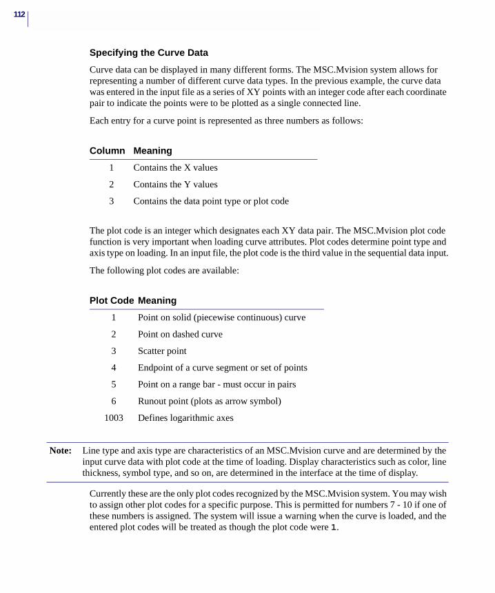
112
Specifying the Curve Data
Curve data can be displayed in many different forms. The MSC.Mvision system allows for representing a number of different curve data types. In the previous example, the curve data was entered in the input file as a series of XY points with an integer code after each coordinate pair to indicate the points were to be plotted as a single connected line.
Each entry for a curve point is represented as three numbers as follows:
The plot code is an integer which designates each XY data pair. The MSC.Mvision plot code function is very important when loading curve attributes. Plot codes determine point type and axis type on loading. In an input file, the plot code is the third value in the sequential data input.
The following plot codes are available:
Currently these are the only plot codes recognized by the MSC.Mvision system. You may wish to assign other plot codes for a specific purpose. This is permitted for numbers 7 - 10 if one of these numbers is assigned. The system will issue a warning when the curve is loaded, and the entered plot codes will be treated as though the plot code were 1.
Column Meaning
1 Contains the X values
2 Contains the Y values
3 Contains the data point type or plot code
Plot Code Meaning
1 Point on solid (piecewise continuous) curve
2 Point on dashed curve
3 Scatter point
4 Endpoint of a curve segment or set of points
5 Point on a range bar - must occur in pairs
6 Runout point (plots as arrow symbol)
1003 Defines logarithmic axes
Note: Line type and axis type are characteristics of an MSC.Mvision curve and are determined by the input curve data with plot code at the time of loading. Display characteristics such as color, line thickness, symbol type, and so on, are determined in the interface at the time of display.
113CHAPTER 4Creating Databanks
Plot code 4 indicates that a point is the final point of a curve segment or set of scatter points. The point type is always assumed to be the same as the preceding point. The plot code can be important, for example, if a curve contains different point types, such as a solid line that changes to a dashed line at a certain point and then has scatter points. Use plot code 4 to terminate any set of point types when multiple point types are loaded. It is good practice to terminate all curve data input with a plot code 4.
The axis type of a curve is determined by the plot code functions on loading. The default axes of all curves when loaded is linear/linear unless specified otherwise via the plot codes in the input file.
To load, one or both axes of a curve as logarithmic, include the plot code definition entry in the set of values being loaded for the curve. An axis plot code definition consists of X-axis flag, Y-axis flag, and the plot code 1003.
The plot code 1003 designating logarithmic axes appears as the third item of a coordinate set that is not an XY coordinate pair. The first two items are integer flags for the X-axis and Y-axis, respectively, designating whether the axis is linear or logarithmic.
A 0 denotes linear and a 1 denotes logarithmic. Only one axis plot code definition is allowed per curve and is typically placed after the last point in the data being loaded. The default (absence of an axis definition entry) specifies linear/linear axes.
The axis definition entries which are available for curve loading are:
The following curves illustrate the effect of the different plot codes.
Solid and Dashed Curves
Plot code 1 designates that the input points will be connected by a solid line. Plot code 2 designates that the input points will be connected by a dashed line. These plot codes can be used for all points on a curve, or for only a selected number of points.
1 0 1003 X-axis logarithmic
0 1 1003 Y-axis logarithmic
1 1 1003 both axes logarithmic
Note: In the following examples the data points on the curves are shown as round dot symbols so that you can readily identify the points with their numerical input values and plot codes.
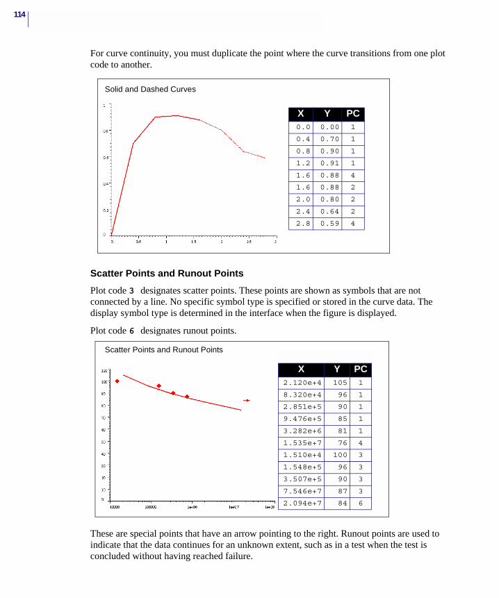
114
For curve continuity, you must duplicate the point where the curve transitions from one plot code to another.
Scatter Points and Runout Points
Plot code 3 designates scatter points. These points are shown as symbols that are not connected by a line. No specific symbol type is specified or stored in the curve data. The display symbol type is determined in the interface when the figure is displayed.
Plot code 6 designates runout points.
These are special points that have an arrow pointing to the right. Runout points are used to indicate that the data continues for an unknown extent, such as in a test when the test is concluded without having reached failure.
X Y PC0.0 0.00 1
0.4 0.70 1
0.8 0.90 1
1.2 0.91 1
1.6 0.88 4
1.6 0.88 2
2.0 0.80 2
2.4 0.64 2
2.8 0.59 4
Solid and Dashed Curves
X Y PC2.120e+4 105 1
8.320e+4 96 1
2.851e+5 90 1
9.476e+5 85 1
3.282e+6 81 1
1.535e+7 76 4
1.510e+4 100 3
1.548e+5 96 3
3.507e+5 90 3
7.546e+7 87 3
2.094e+7 84 6
Scatter Points and Runout Points
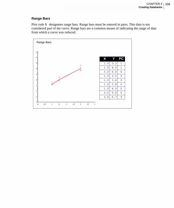
115CHAPTER 4Creating Databanks
Range Bars
Plot code 5 designates range bars. Range bars must be entered in pairs. This data is not considered part of the curve. Range bars are a common means of indicating the range of data from which a curve was reduced.
X Y PC1.0 3.2 1
1.5 4.0 1
3.0 6.0 4
1.0 3.1 5
1.0 3.6 5
1.5 3.8 5
1.5 4.5 5
3.0 5.6 5
3.0 6.7 5
Range Bars
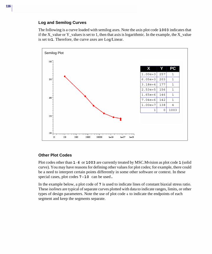
116
Log and Semilog Curves
The following is a curve loaded with semilog axes. Note the axis plot code 1003 indicates that if the X_value or Y_values is set to 1, then that axis is logarithmic. In the example, the X_value is set to1. Therefore, the curve axes are Log/Linear.
Other Plot Codes
Plot codes other than 1-6 or 1003 are currently treated by MSC.Mvision as plot code 1 (solid curve). You may have reasons for defining other values for plot codes; for example, there could be a need to interpret certain points differently in some other software or context. In these special cases, plot codes 7-10 can be used.
In the example below, a plot code of 7 is used to indicate lines of constant biaxial stress ratio. These isolines are typical of separate curves plotted with data to indicate ranges, limits, or other types of design parameters. Note the use of plot code 4 to indicate the endpoints of each segment and keep the segments separate.
X Y PC1.00e+3 257 1
6.05e+3 203 1
3.18e+4 177 1
2.53e+5 156 1
1.65e+6 146 1
7.04e+6 142 1
1.00e+7 138 4
1 0 1003
Semilog Plot
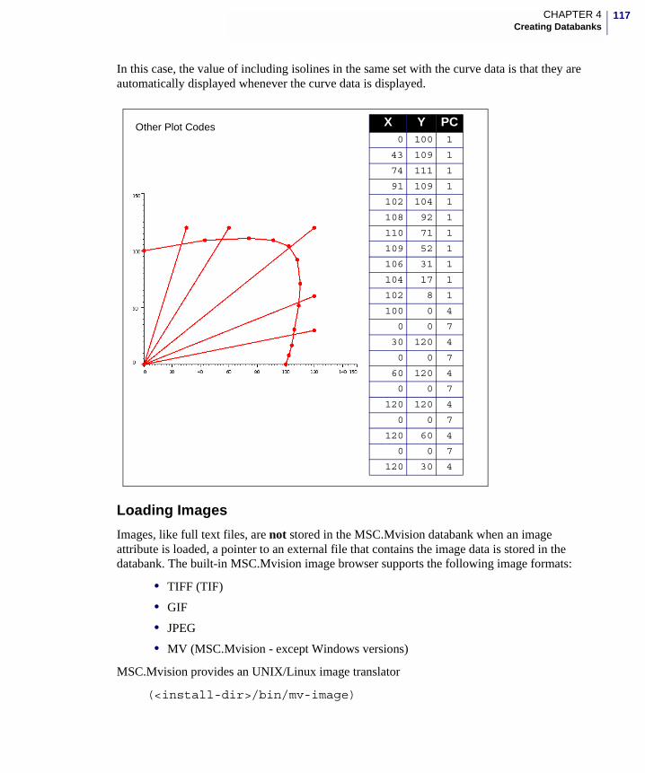
117CHAPTER 4Creating Databanks
In this case, the value of including isolines in the same set with the curve data is that they are automatically displayed whenever the curve data is displayed.
Loading Images
Images, like full text files, are not stored in the MSC.Mvision databank when an image attribute is loaded, a pointer to an external file that contains the image data is stored in the databank. The built-in MSC.Mvision image browser supports the following image formats:
• TIFF (TIF)
• GIF
• JPEG
• MV (MSC.Mvision - except Windows versions)
MSC.Mvision provides an UNIX/Linux image translator
(<install-dir>/bin/mv-image)
X Y PC 0 100 1
43 109 1
74 111 1
91 109 1
102 104 1
108 92 1
110 71 1
109 52 1
106 31 1
104 17 1
102 8 1
100 0 4
0 0 7
30 120 4
0 0 7
60 120 4
0 0 7
120 120 4
0 0 7
120 60 4
0 0 7
120 30 4
Other Plot Codes
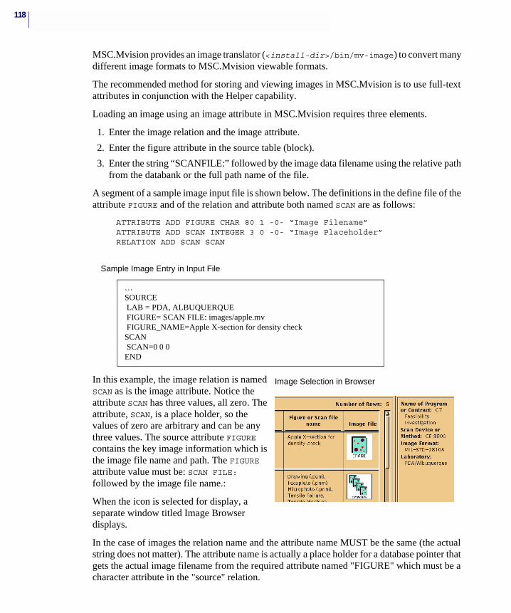
118
MSC.Mvision provides an image translator (<install-dir>/bin/mv-image) to convert many different image formats to MSC.Mvision viewable formats.
The recommended method for storing and viewing images in MSC.Mvision is to use full-text attributes in conjunction with the Helper capability.
Loading an image using an image attribute in MSC.Mvision requires three elements.
1. Enter the image relation and the image attribute.
2. Enter the figure attribute in the source table (block).
3. Enter the string “SCANFILE:” followed by the image data filename using the relative path from the databank or the full path name of the file.
A segment of a sample image input file is shown below. The definitions in the define file of the attribute FIGURE and of the relation and attribute both named SCAN are as follows:
ATTRIBUTE ADD FIGURE CHAR 80 1 -0- “Image Filename”ATTRIBUTE ADD SCAN INTEGER 3 0 -0- “Image Placeholder”RELATION ADD SCAN SCAN
In this example, the image relation is named SCAN as is the image attribute. Notice the attribute SCAN has three values, all zero. The attribute, SCAN, is a place holder, so the values of zero are arbitrary and can be any three values. The source attribute FIGURE contains the key image information which is the image file name and path. The FIGURE attribute value must be: SCAN FILE: followed by the image file name.:
When the icon is selected for display, a separate window titled Image Browser displays.
In the case of images the relation name and the attribute name MUST be the same (the actual string does not matter). The attribute name is actually a place holder for a database pointer that gets the actual image filename from the required attribute named "FIGURE" which must be a character attribute in the "source" relation.
…SOURCE LAB = PDA, ALBUQUERQUE FIGURE= SCAN FILE: images/apple.mv FIGURE_NAME=Apple X-section for density checkSCAN SCAN=0 0 0END
Sample Image Entry in Input File
Image Selection in Browser
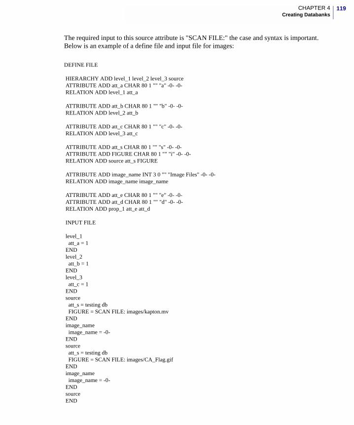
119CHAPTER 4Creating Databanks
The required input to this source attribute is "SCAN FILE:" the case and syntax is important. Below is an example of a define file and input file for images:
DEFINE FILE
HIERARCHY ADD level_1 level_2 level_3 source ATTRIBUTE ADD att_a CHAR 80 1 "" "a" -0- -0- RELATION ADD level_1 att_a
ATTRIBUTE ADD att_b CHAR 80 1 "" "b" -0- -0- RELATION ADD level_2 att_b
ATTRIBUTE ADD att_c CHAR 80 1 "" "c" -0- -0- RELATION ADD level_3 att_c
ATTRIBUTE ADD att_s CHAR 80 1 "" "s" -0- -0- ATTRIBUTE ADD FIGURE CHAR 80 1 "" "i" -0- -0- RELATION ADD source att_s FIGURE
ATTRIBUTE ADD image_name INT 3 0 "" "Image Files" -0- -0- RELATION ADD image_name image_name
ATTRIBUTE ADD att_e CHAR 80 1 "" "e" -0- -0- ATTRIBUTE ADD att_d CHAR 80 1 "" "d" -0- -0- RELATION ADD prop_1 att_e att_d
INPUT FILE
level_1 att_a = 1 END level_2 att_b = 1 END level_3 att_c = 1 END source att_s = testing db FIGURE = SCAN FILE: images/kapton.mv END image_name image_name = -0- END source att_s = testing db FIGURE = SCAN FILE: images/CA_Flag.gif END image_name image_name = -0- END source END
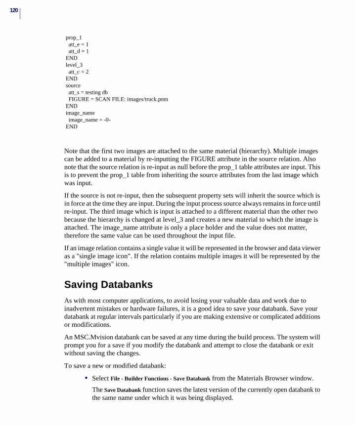
120
prop_1 att_e = 1 att_d = 1 END level_3 att_c = 2 END source att_s = testing db FIGURE = SCAN FILE: images/truck.pnm END image_name image_name = -0- END
Note that the first two images are attached to the same material (hierarchy). Multiple images can be added to a material by re-inputting the FIGURE attribute in the source relation. Also note that the source relation is re-input as null before the prop_1 table attributes are input. This is to prevent the prop_1 table from inheriting the source attributes from the last image which was input.
If the source is not re-input, then the subsequent property sets will inherit the source which is in force at the time they are input. During the input process source always remains in force until re-input. The third image which is input is attached to a different material than the other two because the hierarchy is changed at level_3 and creates a new material to which the image is attached. The image_name attribute is only a place holder and the value does not matter, therefore the same value can be used throughout the input file.
If an image relation contains a single value it will be represented in the browser and data viewer as a "single image icon". If the relation contains multiple images it will be represented by the "multiple images" icon.
Saving DatabanksAs with most computer applications, to avoid losing your valuable data and work due to inadvertent mistakes or hardware failures, it is a good idea to save your databank. Save your databank at regular intervals particularly if you are making extensive or complicated additions or modifications.
An MSC.Mvision databank can be saved at any time during the build process. The system will prompt you for a save if you modify the databank and attempt to close the databank or exit without saving the changes.
To save a new or modified databank:
• Select File - Builder Functions - Save Databank from the Materials Browser window.
The Save Databank function saves the latest version of the currently open databank to the same name under which it was being displayed.

121CHAPTER 4Creating Databanks
If the current databank is open in the spreadsheet, use the Save Databank function available in the spreadsheet databank menu.
To save a databank under a different name:
1. Select File - Builder Functions - Save Databank As… option.
The Save Databank As… function saves the latest version of the currently open databank under a user-specified file name.
When the option is selected, a window is displayed showing the current file name and path so that you can easily modify the selection.
2. Select a name or enter a different file name in the current path.
OR
2. Navigate to a remote directory and save the databank to the selected or enter a file name.

122
MSC.Mvision Builder and Evaluator 2002 Installation Guide
5 Revising Schemas and Databanks
� Overview
� Reviewing and Revising Schemas
� Revising Attributes
� Modifying Data
� Rebuilding Databanks
124
OverviewMSC.Mvision includes many functions that allow you to make changes to both schema and databanks by using the Builder Functions under the File function on the menu bar of the Materials Browser and the put and modify commands in the spreadsheet, the batch builder programs and the DPI interface. The Builder Function menu contains various editing options that allow you to review and revise your schema and databank, modify a databank, correct errors, perform maintenance and make general improvements in the databank.
This chapter gives you information on reviewing schemas by listing relations and displaying the hierarchy. Revising schemas by editing and adding attributes. Modifying databanks by adding, revising and deleting data, and reloading the databank after it has been modified.
After you have initialized the databank, created the data input file, created a prototype, loaded data into the databank and saved the databank, you can revise the schema and data from within the MSC.Mvision interface. The editing capabilities of MSC.Mvision are typically used to correct common errors in a new databank such as:
• Empty Attributes - attribute names which have no values in the databank.
• Empty Relations - relations that contain no attributes.
• Duplicate Data Entries - attribute values that are technically the same, but differ syntactically.
• Data Integrity - checking data stored in the databank against the source data.
There are many ways of checking and making the corrections to the schema and databank. You will want to compare the loaded data to the data and query the databank for specific attributes to verify format. These checks and verifications may require that you to edit attributes in the schema or revise data in the databank.
125CHAPTER 5Revising Schemas and Databanks
Reviewing and Revising SchemasThis section includes information on listing the relations and displaying the hierarchy of the databank.
Listing Relations and AttributesRelations (tables) and how they relate to each other (hierarchy) form the basis for the databank structure and organization. When building a databank, you will want to check the list of relations that have been defined in the current databank by hierarchy level. To accommodate this, the List Attribute… option from the File - Builder Functions menu lists the attributes and attribute parameters which have been assigned to each relation.
The format of each entry in the listing is attribute name, description, units, precision, relation name, and data type.
To review or list the data including footnotes and metadata in a databank, perform the following steps:
1. Open the databank.
2. Click View - Hierarchy View.
3. Query or select the material and relation you want to review.
4. Select a data row in the Materials Browser or Data Viewer and select File - Builder Functions - Data Editor or the Data Editor option from the popup menu to display the data editor window.
This window lists the attributes assigned to the selected hierarchy level relation (contents of table row). Only the attributes assigned to the selected relation that have values which have been loaded for the selected row are displayed. Clicking the arrow button to the right of the listed attribute displays a list of all values which are loaded for this attribute. You can also list existing footnotes and metadata using this window.
Displaying and Modifying HierarchyTo review the organization of relations and attributes in an MSC.Mvision databank, open a databank and:
1. Select View - Hierarchy View from the Materials Browser.
The databank hierarchy levels are displayed as index cards with the relation name on the tab. The order (hierarchy) of the relations is the highest level on the bottom of the displayed stack. The name of the attributes which are assigned to the relations are shown on the face of the card. The order from left to right of the attributes is not of any importance in the databank organization.

126
The hierarchy structure of an MSC.Mvision databank cannot be revised using the interactive interface or the batch builder programs. You can rename relations and add data relations using the interactive interface, but you may prefer to perform these actions externally via the batch builder programs or define/input files.
Adding and revising attributes can be performed within the program and are detailed in the Revising Attributes section of this chapter.
To modify the hierarchy of an existing databank, you must edit the define file and recreate the databank. This means adding or changing the relation command and the hierarchy command in the define file. This will also usually require changes in the input file to accommodate the changes in databank structure.
If you have a define file from which you built the databank, you can edit this file using one of the edit buttons such as Builder Function - New Databank or you can externally edit the file. If you do not have a current define file for the databank, you can use the Builder Function - Write Databank feature to create one.
You may also want to create an input file at this time for editing to be used for reloading the data. After the define file has been edited, you can rebuild the databank, review the new databank to verify the modifications, make any changes which may be required for the input file, and reload the data.
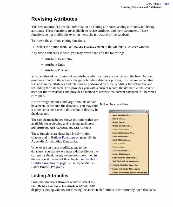
127CHAPTER 5Revising Schemas and Databanks
Revising AttributesThis section provides detailed information on editing attributes, adding attributes and listing attributes. These functions are available to revise attributes and their parameters. These functions do not modify the existing hierarchy (structure) of the databank.
To access the attribute editing functions:
1. Select the option from File - Builder Functions menu in the Materials Browser window.
Any time a databank is open, you may review and edit the following:
• Attribute Description
• Attribute Units
• Attribute Precision
You can also add attributes. Other attribute edit functions are available in the batch builder programs. Early in the schema design or building databank process, it is recommended that revisions to the attributes and relations be performed by directly editing the define file and rebuilding the databank. This provides you with a current record, the define file, that can be used for future revisions and provides a method to recreate the current databank if it becomes corrupted.
As the design matures and large amounts of data have been loaded into the databank, you may find it more convenient to edit the attributes directly in the databank.
The sample menu below shows the options that are available for reviewing and revising attributes: Edit Attribute, Add Attribute, and List Attribute.
These functions are described briefly in this chapter and in Builder Functions on page 164 in Appendix A - Building Databanks.
Whenever you make modifications to the databank, you can always erase a define file for the current databank, using the methods described in the section at the end of this chapter, or the Batch Builder Programs on page 176 in Appendix B - Batch Builder Programs.
Listing AttributesFrom the Materials Browser window, select the File - Builder Functions - List Attribute option. This displays a popup window for viewing the attribute definitions in the currently open databank.
Builder Functions Menu
128
Use the scroll bar to scan through the list of attributes or search the list for keywords by typing in the search cell and clicking on the arrow buttons.
The information displayed in the attributes list is the attribute name, description, units, precision, relation name to which it is assigned and the basic data type (REAL, INTEGER, or STRING).
Editing AttributesFrom the Materials Browser window, select the File - Builder Functions - Edit Attribute… option. This displays the Edit Attribute window which allows you to change the parameters of an existing attribute definition in the currently open databank.
To edit an existing attribute definition using the Edit Attribute window, use the following steps:
1. After opening the window, click the arrow button to the right of the Name cell in the top section of the window to display a list of all attributes in the current databank.
2. Select the attribute name from those listed and click the OK button in the attribute list.
OR
3. Type in the attribute name in the cell directly.
After the attribute name is selected, the parameters for the selected attribute display in the window.
The editable parameters are shown in the center window pane labeled Edit The Fields Here.
4. Click in the appropriate cell or cells and modify the text to edit the attribute parameters.
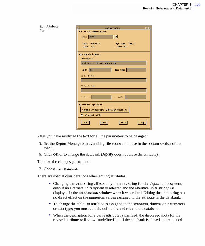
129CHAPTER 5Revising Schemas and Databanks
After you have modified the text for all the parameters to be changed:
5. Set the Report Message Status and log file you want to use in the bottom section of the menu.
6. Click OK or to change the databank (Apply does not close the window).
To make the changes permanent:
7. Choose Save Databank.
There are special considerations when editing attributes:
• Changing the Units string affects only the units string for the default units system, even if an alternate units system is selected and the alternate units string was displayed in the Edit Attribute window when it was edited. Editing the units string has no direct effect on the numerical values assigned to the attribute in the databank.
• To change the table, an attribute is assigned to the synonym, dimension parameters or data type; you must edit the define file and rebuild the databank.
• When the description for a curve attribute is changed, the displayed plots for the revised attribute will show “undefined” until the databank is closed and reopened.
Edit Attribute Form
130
Adding AttributesThe File - Builder Functions - Add Attribute… option in the Materials Browser displays the Add Attribute window that allows you to add new attributes to the schema in an existing databank.
Use the Add Attribute option to create and add new attributes to existing relations (Hierarchy or Data Relations). You can also create new attributes with new relations at the data relation (property set) level of the hierarchy. Any relation that is specified in the add attribute process which does not currently exist is created as a data relation (property set).
When a databank is opened and the add attribute window is displayed, you can add attributes using the following steps:
1. Click the arrow button to the right of the table name cell. A list of existing relations display.
2. Select the relation for adding the new attribute.
3. Click on the name in the list or type a name in the table name cell to create a new data relation to which the new attribute is added.
4. Type the name for the new attribute in the name cell. This name must be a valid attribute name.
5. Choose the data type for the new attribute by selecting Type and clicking on the appropriate data type in the popup menu
Available data types are listed.
All data types are actually subtypes of three basic data types: REAL, INTEGER, or CHARACTER. For example, FIGURE which allows you to create curve attributes is a special case of REAL. IMAGE which creates an image attribute, is a special case of INTEGER. FULLTEXT is a special case of character or STRING.
Selecting the data type automatically configures the add attribute window and enables the required parameter cells.
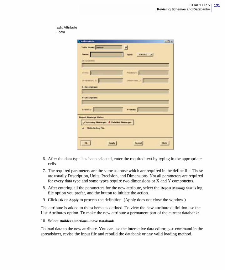
131CHAPTER 5Revising Schemas and Databanks
6. After the data type has been selected, enter the required text by typing in the appropriate cells.
7. The required parameters are the same as those which are required in the define file. These are usually Description, Units, Precision, and Dimensions. Not all parameters are required for every data type and some types require two dimensions or X and Y components.
8. After entering all the parameters for the new attribute, select the Report Message Status log file option you prefer, and the button to initiate the action.
9. Click Ok or Apply to process the definition. (Apply does not close the window.)
The attribute is added to the schema as defined. To view the new attribute definition use the List Attributes option. To make the new attribute a permanent part of the current databank:
10. Select Builder Functions - Save Databank.
To load data to the new attribute. You can use the interactive data editor, put command in the spreadsheet, revise the input file and rebuild the databank or any valid loading method.
Edit Attribute Form
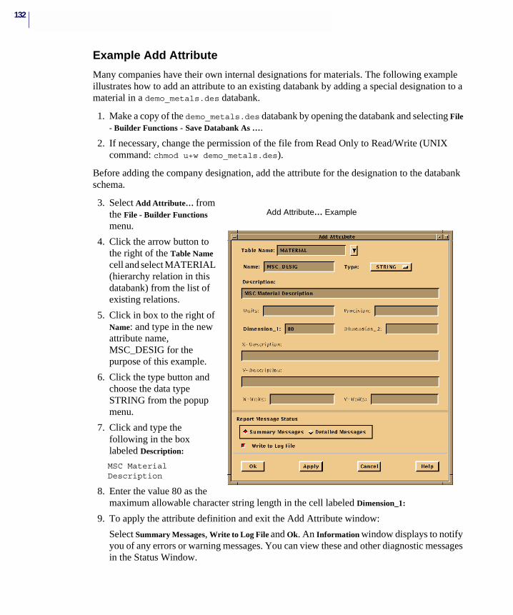
132
Example Add Attribute
Many companies have their own internal designations for materials. The following example illustrates how to add an attribute to an existing databank by adding a special designation to a material in a demo_metals.des databank.
1. Make a copy of the demo_metals.des databank by opening the databank and selecting File - Builder Functions - Save Databank As ….
2. If necessary, change the permission of the file from Read Only to Read/Write (UNIX command: chmod u+w demo_metals.des).
Before adding the company designation, add the attribute for the designation to the databank schema.
3. Select Add Attribute… from the File - Builder Functions menu.
4. Click the arrow button to the right of the Table Name cell and select MATERIAL (hierarchy relation in this databank) from the list of existing relations.
5. Click in box to the right of Name: and type in the new attribute name, MSC_DESIG for the purpose of this example.
6. Click the type button and choose the data type STRING from the popup menu.
7. Click and type the following in the box labeled Description:
MSC Material Description
8. Enter the value 80 as the maximum allowable character string length in the cell labeled Dimension_1:
9. To apply the attribute definition and exit the Add Attribute window:
Select Summary Messages, Write to Log File and Ok. An Information window displays to notify you of any errors or warning messages. You can view these and other diagnostic messages in the Status Window.
Add Attribute… Example
133CHAPTER 5Revising Schemas and Databanks
The databank is now ready to accept input that loads data values to the new attribute in the material hierarchy relation.
Adding Data to an Attribute. For this example, one of the following methods of loading data to a new attribute can be used.
As of Version 2002 the following input file command provide precise additions of data to MSC.Mvision databanks. Create an input file named modify.inp to MSC_DESIG as shown below to add a value
For all material table rows that contain the value “A97075” for attribute named “UNS”.
For this example, the input file is named modify.inp
MSC.Mvision does support continue to support the method described below. The file to be created is similar to a regular input file except, a pound sign (#) is placed in front of the attributes you want to match and the attributes you want to load are entered without a pound sign. In this example, the attribute name UNS is marked with the pound sign and the new attribute MSC_DESIG is not. For the example, enter the following commands in the modify.inp file using a text editor.
10. For either loading methods. To load the new attribute values: Choose File - Builder Functions - Read Data… option and read in file modify.inp.
The result of this action is the same for both methods. Two data rows are updated and the value AL-7075 is added to the two materials that have the value A97075 for the attribute UNS. Because the only change occurring is to the hierarchy relation material, the input file only needs to include enough information to match the hierarchy relation and not any information for the relations below.
The above described procedures can be used to add data to a specific material (table row) or can be used to make global additions; for example, add defined data to every material that contains matched attributes.
MATERIALUPDATE CONDITIONS = UNS = A97075MSC_DESIG = AL-7075
END
MATERIAL#UNS = A97075MSC_DESIG = AL-7075
Note: You must mark the attributes that you are using to guide the addition with a pound sign by marking the attributes that must match existing data.
134
Modifying DataThis section includes details for loading data to a new databank and modifying data in an existing databank. These functions can be used to revise data row specific parameters or can be used to perform global changes to databank attribute values.
Data in an existing MSC.Mvision databank can also be modified using the Batch Builder Program described in Appendix B - Batch Builder Programs on page 175.
Adding New DataAs of version 2002 the UPDATE_CONDTIONS and LOCATE_CONDITIONS commands in an input file provided very precise and efficient control for updating and adding data to existing MSC.Mvision databanks.
UPDATE_CONDITIONS
When the UPDATE_CONDITIONS command is included in an input file the system will locate and modify the table row and/or attribute values as specified in the command. Using this command one or many attribute values can be added or modified for a single table row or multiple table rows. The format of an UPDATE_CONDITIONS command is:
<table name to which the query is applied>UPDATE_CONDITIONS = <valid query_condition for databank><attribute name> = <value>END
For example if a databank contained a single entry for UNS = A97075 then the following input file segment would change the value of the MSC_DESIG attribute for a single table row;
MATERIALUPDATE_CONDITIONS = UNS = 'A97075'MSC_DESIG = new_valueEND
If there were multiple entries for UNS = A97075 then the above command would have modified all the existing MSC_DESIG for those table rows and would have added the attribute value if it did not previously exist.
The UPDATE_CONDITIONS command can be used to modify or add values for any attribute type including curve attributes (any input that is value in an input file). The query for UPDATE_CONDITIONS can be any valid MSC.Mvision query that returns a result (table row) to include queries on curve values or interpolations. The query is not restricted to attributes in the table being updated the query can apply to any table in the material path that returns the required table row.
For example, if a material path contained the table material with the attribute MSC_DESIG and a MECHANICAL table with the attribute E11T = 99, then the following command would modify the MSC_DESIG for the MATERIAL table in the material path;
MATERIAL
135CHAPTER 5Revising Schemas and Databanks
UPDATE_CONDITIONS = E11T = 99MSC_DESIG = new_valueEND
The UPDATE_CONDITIONS can be used in conjunction with the UID (Unique identifier) to precisely identify and update a table row for example:
MATERIALUPDATE_CONDITIONS = UID = material-default-1MSC_DESIG = new_valueEND
The UPDATE_CONDITIONS can be used to update SOURCE attribute value for specific property set tables (data relations) by including the SOURCE attribute definition within the property table. For example if BASIS is a source attribute the value of BASIS can be set or modified for a MECHANICAL property table using the following input file;
MECHANICALUPDATE_CONDITIONS = E11T = 99BASIS = new_valueEND
The UPDATE_CONDITIONS command can be included in any input file for building or modifying an MSC.Mvision databank. If an error is encountered for specifying the attribute values or the query the build/load will be inhibited and no data will be committed. If the condition query returns zero rows this will return an error and no data will be committed. If used in conjunction with other input formats and commands the UPDATE_CONDITIONS block must be followed by another UPDATE_CONDITIONS block, a LOCATE_CONDITIONS block or the top level hierarchy block to prevent an ambiguous condition.
LOCATE_CONDITIONS
When the LOCATE_CONDITIONS command is included in an input file the system will locate and add the table data immediately following the command in the input file to the identified table row. In other words the command finds a precise material path (table row with connected hierarchy) and attaches the following defined table data to the path. Using this command one or many rows of table data can be added to a single table row or multiple table rows.
The format of a LOCATE_CONDITIONS command is (the LOCATE_CONDITIONS command MUST be the only command in the block):
<table name of table to which the query is applied>LOCATE_CONDITIONS = <valid query_condition for databank>END
followed by tables blocks to be added.
For example, if a databank contained a single entry for UNS = A97075 then the following input file segment would add the DETAILS table row to the material path for the table row containing UNS = A97075;
136
MATERIALLOCATE_CONDITIONS = UNS = 'A97075'ENDDETAILSFORM = new_formEND
If there were multiple entries for UNS = A97075 then the above command would have added the DETAILS table row for those table rows.
The LOCATE_CONDITIONS command can be used add table data of any type including curve data (any input that is value in an input file). The query for LOCATE_CONDITIONS can be any valid MSC.Mvision query that returns a result (table row) to include queries on curve values or interpolations. The query is not restricted to attributes in the table being addressed the query can apply to any table in the material path that returns the required table row. The table row that is attached to is the table row in the addressed table returned by the query. For example if a material path contained the table MATERIAL and a MECHANICAL table with the attribute E11T = 99, then the following command would add the table data to the ENVIRON table for the same material path; MATERIAL
LOCATE_CONDITIONS = E11T = 99ENDENVIRONTEMP = 70END
The LOCATE_CONDITIONS can be used in conjunction with the UID (Unique identifier) to precisely identify and add table data for example:
MATERIALLOCATE_CONDITIONS = UID = material-default-1ENDENVIRONTEMP = 70END
The LOCATE_CONDITIONS can be used to add SOURCE attribute values for specific property set tables (data relations) by including the SOURCE attribute definition within the property table.
For example if BASIS is a source attribute the value of BASIS can be added for a MECHANICAL property table using the following input file;
ENVIRONLOCATE_CONDITIONS = TEMP = 70ENDMECHANICALE11T = 99BASIS = new_valueEND
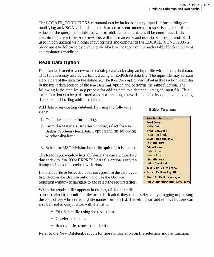
137CHAPTER 5Revising Schemas and Databanks
The LOCATE_CONDITIONS command can be included in any input file for building or modifying an MSC.Mvision databank. If an error is encountered for specifying the attribute values or the query the build/load will be inhibited and no data will be committed. If the condition query returns zero rows this will return an error and no data will be committed. If used in conjunction with other input formats and commands the LOCATE_CONDITIONS block must be followed by a valid table block or the top level hierarchy table block to prevent an ambiguous condition.
Read Data Option
Data can be loaded to a new or an existing databank using an input file with the required data. This function may also be performed using an EXPRESS data file. The input file may contain all or a part of the data for the databank. The Read Data option described in this section is similar to the input/data section of the New Databank option and performs the same function. The following is the step-by-step process for adding data to a databank using an input file. This same function can be performed as part of creating a new databank or by opening an existing databank and loading additional data.
Add data to an existing databank by using the following steps:
1. Open the databank for loading.
2. From the Materials Browser window, select the File - Builder Functions - Read Data… option and the following window displays:
3. Select the MSC.Mvision input file option if it is not set.
The Read Input window lists all files in the current directory that end with .inp. If the EXPRESS data file option is set, the listing includes files ending with .data.
If the input file to be loaded does not appear in the displayed list, click on the Browse button and use the Browse Selection window to navigate to and select the required files.
When the required file appears in the list, click on the file name to select it. If multiple files are to be loaded, they can be selected by dragging or pressing the control key while selecting file names from the list. The edit, clear, and remove buttons can also be used in conjunction with the list to:
• Edit Select file using the text editor
• Unselect file names
• Remove file names from the list
Refer to the New Databank section for more information on file selection and list function.
Builder Functions
138
4. After selecting the input file, verify that the databank displayed in the databank cell is the one to which the data is to be loaded. If not, click on the arrow button to the right of the cell. A list of the currently open databanks displays. Select the appropriate databank by clicking on the item in the list.
5. If this is the first time the input file is used with this databank, it is recommended that you select Check Only and execute the file without affecting the current databank. Whether Check Only is set or not, the checking is always performed for each loading of the data. The only difference is that no attempt is made to modify the databank if Check Only is set.
6. Set the Report Message Status and Log File to the preferred state and click on the OK button to load the data from the selected input files. When loading is complete, an information window displays showing the status and a count of information, warning and error messages. Messages can be reviewed in the status window or the Builder.Log file. Note as in the New Databank process an error in the input data inhibits the load process and no data will be added to the current databank. Refer to the New Databank section for information on the Diagnostic Messages.
The above process can be repeated as many times as required to correct any errors and to load the specified data. It is important to note that any loaded New or Modified data is not a permanent part of the current databank until the databank is saved. To remove data that has been loaded but not saved, close the current databank and answer No to the Save Confirmation window.
The Put Command
New data can be added to an existing databank by loading the data using the put command in the spreadsheet. This command is described in detail in the MSC.Mvision Builder and Evaluator User’s Guide and Reference and it is described in this section.
To add new data from the spreadsheet to an MSC.Mvision databank, you can use the put command. The format of the command is shown below. This command can be entered by clicking on a cell in the spreadsheet and choosing the command from the Paste Function list and then editing the command arguments.
put(databank, attributes, instances)
The put command requires three arguments to place data into a databank:
1. Databank - filename of the databank to which the data is to be loaded.
2. Attributes - attribute names from the subject databank which uniquely identify where in the databank the data is to be loaded.
3. Instances - values which correspond to the defined attributes which identify the loaded data. This includes the data values to be matched and the new values to be loaded.
Note: When loading data, all instances (values) must match the data type of the attribute being loaded or an error results. Precision is applied at the time of loading the actual value in the databank is the rounded value.
139CHAPTER 5Revising Schemas and Databanks
To enter and execute a put command in the MSC.Mvision spreadsheet:
1. Select a cell.
2. Select Function - Paste Function… - put.
3. Edit the parameters in the put command.
4. Set up the cells containing the attribute names and instances.
5. Select the command cell again.
6. Press <Return>.
The MSC.Mvision spreadsheet is a very powerful tool for manipulating, adding and modifying data in an MSC.Mvision databank.
To become familiar with the MSC.Mvision spreadsheet functions and capabilities refer to the MSC.Mvision Builder and Evaluator User’s Guide and Reference.
The Modify Command
In the MSC.Mvision spreadsheet, the put command is used to add new data to a databank as described above. The modify command is a similar function that uses a query condition to selectively revise or add data to existing entries in an MSC.Mvision databank. It is generally good practice to save your databank before attempting a modify command.
Similar to the put command, the modify command can be entered by clicking on a cell in the spreadsheet and choosing the command from the Paste Function list and editing the command arguments.
The format for the modify command is as follows:
modify(databank,query,attributes,instances)
The modify command requires the following parameters:
Note: A UID cannot be specified in a spreadsheet put command the UID for a put table row is always system generated for the current default name space.
databank Filename of the databank, which must be currently open in MSC.Mvision Builder. The databank argument must include the relative path or the full path. Enclose the databank name in quotes ("text") if you type it in the command. The databank can also be a reference to a cell that contains the name of the databank.
If you are using a pre-3.0 version of the spreadsheet, this parameter may have been des, tes, or ana. The spreadsheet still supports the earlier syntax by mapping this parameter to the specific databank name and path via a link window mechanism.
140
Example Modify Command
This command first extracts all data rows with the attribute UNS value like A96061 and changes all occurrences of UNS to A96T61 and all occurrences of attribute cname to 6T61 Aluminum Alloy for the selected data rows in the databank Alloy.des.
query The query conditions must be specified exactly for which rows of the databank are to be modified. The query format for the modify command is the same as that used in the Databank - Select… command. Refer to the MSC.Mvision Builder and Evaluator User’s Guide and Reference for detailed information on queries in the spreadsheet.
We recommend that you use the Select panel to select from the databank to test the query and verify that the required data rows are being addressed. Before you modify the databank, refer to the MSC.Mvision Builder and Evaluator User’s Guide and Reference for detailed information on the select command and operations.
Then apply the same query condition in the modify formula to make sure you are changing the correct materials. The Select panel places the select query conditions in a separate cell. You can use this query condition in a modify command by referencing the location of the select query cell in the modify command.
attributes These are the databank attribute names that will be modified. All of the instances (values) for the specified attributes in the data rows which satisfy the query condition will be replaced with the values specified in the instances argument.
The format for the attributes argument is the same as for a Select command. As with the Query conditions, the attributes arguments can be typed in the command line or can be a cell reference. If you have performed a select command to verify the query, you can reference the cell locations of the cells used for the select command. If the attribute names are added, enclose the entire text string in quotes.
instances These are the values to be loaded into the databank. These values must correspond one-to-one for the specified attributes. These instances are usually listed as columns of cells with the attribute name as the column header and the modify command as a cell reference to the values. All values must match the data type of the associated attribute or an error occurs. As with the put command, attribute precision is applied at the time of loading for real attributes.
Note: A UID cannot be specified as an instance in a spreadsheet modify command, but it can be used in the query to uniquely identify the table row to be modified.
141CHAPTER 5Revising Schemas and Databanks
If the query performed in this modify command is executed again, no data rows would be found because they have all been changed.
The following is an example of a modify command. This modify is changing all occurrences of Aluminum 6061 to 6T61. The modify command is in cell A6.
=modify(“alloy.des”,A2,A7:B7,A8:B8)
Refer to the sample spreadsheet below:
The above example shows the results of a select using the query in Cell A2. This is the contents of the databank before the modify command in cell A6 is executed (the des in the command is the older command syntax which refers to a link to the databank Alloy.des.
The spreadsheet modify command is very powerful. To prevent unintentional changes, the spreadsheet inhibits its operation immediately after you enter the command. To execute the modify, select the cell with the modify command and press <Return>. By referencing the command, you can change specific attribute values by changing the attribute names or instance in the referenced cells and resubmitting the command.
If you find modify has changed data incorrectly, close the databank from the Materials Browser File - Close Databank… menu, answer No to the confirmation dialog asking if you want to save the databank, then reopen the previously saved version of the databank to return to its former state.
You should save your data frequently using the Materials Browser Builder Functions - Save Databank or Save Databank As… option or the spreadsheet Save Databank option in the databank menu, while changing data with modify commands. This is to ensure the data is loaded as you planned and any errors are removed before additional data is modified. It is also a good idea to make a backup of the databank before you start loading or modifying data in case you find that all or some of your modifications were in error.
Example of select and modify (before execution).
Note: If the cells referenced in the attributes argument have already been populated, an error may occur or the attributes may be modified incorrectly. You should be very careful about your actions when working in a modify cell, to avoid inadvertently changing data in a databank. A modify cell executes whenever you press the Return key if in that cell, this will occur when you have completed typing the command for the first time and press <cr>
142
Data Editor Option
The Data Editor… option which is available from the Materials Browser window displays a window which allows you to review and revise the attribute values, footnotes, or metadata in the currently open databank.
Using the Data Editor, you can either edit attribute values within data relations for a selected row of data which is useful for correcting errors or updating individual values in the databank, or you can edit values for hierarchy attributes which may effect many rows in the databank. The Data Editor option performs a similar function as the Spreadsheet Modify command.
The Data Editor option is available in the Data Viewer for both the Flat View and the Hierarchy View. In the Data Viewer, the Data Editor acts on attribute values in a currently displayed data relation and the row selected. In the Materials Browser, the Data Editor Option is only available in the Hierarchy View.
In the Hierarchy display of the Materials Browser, the Data Editor acts on the attribute values in a hierarchy relation currently displayed on the top of the stack and the row selected. Be aware when editing the hierarchy level attribute values because this can effect major portions of the databank. To change the displayed view, select the appropriate option from the view menu in the Materials Browser menu.
To access Data Editor…, use the Materials Browser or Data Viewer window.
1. Select View - Hierarchy View.
2. Select a single row from the databank by clicking on the displayed row to identify the hierarchy table, or the specific row to edit.
3. Select File - Builder Functions - Data Editor… or access the popup menu using the third mouse button from the Materials Browser or the Data Viewer window.
A typical Data Editor window is displayed below:
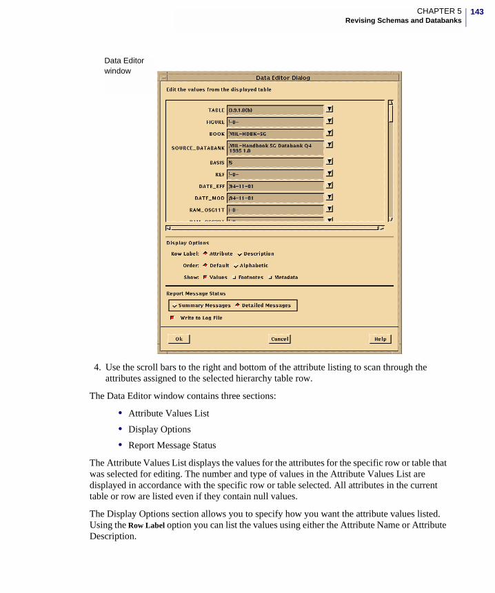
143CHAPTER 5Revising Schemas and Databanks
4. Use the scroll bars to the right and bottom of the attribute listing to scan through the attributes assigned to the selected hierarchy table row.
The Data Editor window contains three sections:
• Attribute Values List
• Display Options
• Report Message Status
The Attribute Values List displays the values for the attributes for the specific row or table that was selected for editing. The number and type of values in the Attribute Values List are displayed in accordance with the specific row or table selected. All attributes in the current table or row are listed even if they contain null values.
The Display Options section allows you to specify how you want the attribute values listed. Using the Row Label option you can list the values using either the Attribute Name or Attribute Description.
Data Editorwindow
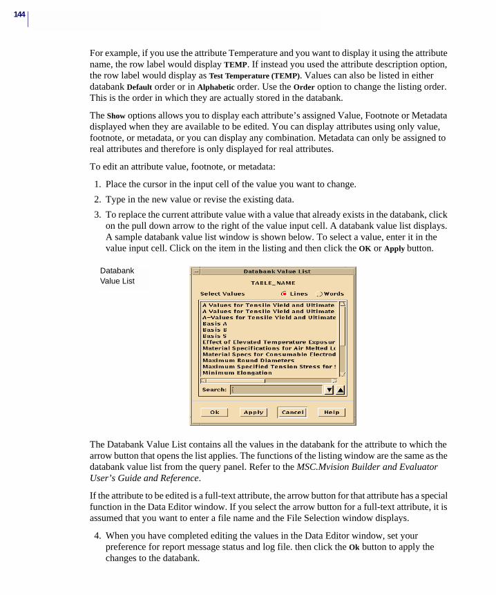
144
For example, if you use the attribute Temperature and you want to display it using the attribute name, the row label would display TEMP. If instead you used the attribute description option, the row label would display as Test Temperature (TEMP). Values can also be listed in either databank Default order or in Alphabetic order. Use the Order option to change the listing order. This is the order in which they are actually stored in the databank.
The Show options allows you to display each attribute’s assigned Value, Footnote or Metadata displayed when they are available to be edited. You can display attributes using only value, footnote, or metadata, or you can display any combination. Metadata can only be assigned to real attributes and therefore is only displayed for real attributes.
To edit an attribute value, footnote, or metadata:
1. Place the cursor in the input cell of the value you want to change.
2. Type in the new value or revise the existing data.
3. To replace the current attribute value with a value that already exists in the databank, click on the pull down arrow to the right of the value input cell. A databank value list displays. A sample databank value list window is shown below. To select a value, enter it in the value input cell. Click on the item in the listing and then click the OK or Apply button.
The Databank Value List contains all the values in the databank for the attribute to which the arrow button that opens the list applies. The functions of the listing window are the same as the databank value list from the query panel. Refer to the MSC.Mvision Builder and Evaluator User’s Guide and Reference.
If the attribute to be edited is a full-text attribute, the arrow button for that attribute has a special function in the Data Editor window. If you select the arrow button for a full-text attribute, it is assumed that you want to enter a file name and the File Selection window displays.
4. When you have completed editing the values in the Data Editor window, set your preference for report message status and log file. then click the Ok button to apply the changes to the databank.
Databank Value List
145CHAPTER 5Revising Schemas and Databanks
Diagnostic information, warning and error messages are written to the status window and the log file. Error messages display in a popup window. All restrictions and requirements for input data also apply to this process.
5. Select Cancel if you want to reject all changes and return to the unedited databank.
If the edits being performed merges or divides (branches), current display may not reflect these changes. If the results of a data editor cannot be seen in the current display, navigate to the top level of the databank, reselect the appropriate rows and redisplay.
To make your changes a permanent part of the databank, use the File - Builder Functions - Save option in the Materials Browser.
Set Default NamespaceAs of version 2002, the MSC.Mvision databank contain a UID (Global Unique Identifier) for every table row within the databank. This UID is a special property of each table row within the databank and is automatically created upon creation of the databank.
The UID consists of three elements:
• table name - name of the table for which the table row is a member
• name space - character string not to exceed 64 characters; it is by default the name of the databank file for which the database was originally created
•• integer row identifier - table_name-name_space-external_id, such as, material-
default-1
The name space can be one of two types: a database managed name space (default name space) or a user-managed name space.
A database managed name space is associated with a specific database and is automatically generated; this is the type of name space created when a database is initialized. A user-managed name space is controlled by the user who specifies the identifiers associated with the specific table rows.
The row identifier is an integer value that combined with the name space is unique to the table for which the table row is a member. When the row identifiers are automatically generated, they are a consecutive series of integers. The “as generated row identifier” is the internal_id.
If a user modifies the UID then an external_id is created. Otherwise both the internal_id and external_id are the same. The name space and/or row identifier can be modified via the MSC.Mvision Builder or the MvBatchBuilder by use of input files.
The current default name space can be set using the File/Builder Functions Set Default Namespace option. The default namespace can be changed and saved for the current databank, by entering a new name in the Set Default Namespace window and clicking OK (See figure
Caution: There is no way to undo changes after the databank has been saved. If you do not want to save the current edits, you must close the databank and answer No to the Save confirmation.
146
"Set Default Namespace Window" and then saving the databank with File/Builder Functions/Save Databank. Temporarily changing the default namespace can be useful in creating input files for other databanks by changing the Default Namespace and writing (dumping) input files.
The Default Namespace is the namespace used for the uid when the data is loaded. This means that if you write (dump) the input files for the current databank and include the uid and then change the default namespace and reload the data. The dumped and reloaded data will have uid's with the previous namespace and new data will be added with the revised (new) namespace.
Revising UnitsTo change the numerical values for an attribute, due to a change in the default units, you must change all the values for the attribute in the input file and rebuild the databank. Note the conversion factors in the external units conversion file are initiated (triggered) by the attribute name not the unit string.
If it becomes necessary to change the default units for some or all attributes after the databank has been created, use the following procedures:
1. Create or modify a units conversion file to include a set of entries with conversion factors for each real attribute as it is to appear in the revised databank. If the attribute is not going to be modified, do not include it in the unit set.
2. Open the subject databank and change the current unit system to the unit set you have just created. Verify the converted values.
3. Write a define and input file for the entire databank using the File - Builder Functions - Write Databank option. Write Databank always writes the data values for the input file in the current units system, but does not effect the default unit string in the define file.
4. Change the attribute units string in the define file that you have just created using File - Builder Functions - Edit Attributes or your text editor.
5. Rebuild the databank using File - Builder Functions - New Databank and the edited define file and input file. The new databank now contains the converted values as default databank values. All units conversions will now apply to the new values. Remove the special unit sets from the units file and modify other unit sets as required.
The previous procedure can also be used to load data if it is not in the preferred form; for example, load the data as received, convert the values, write and rebuild the databank.
Deleting Data
Delete Row Option
For large databanks, it may be inconvenient to rebuild the databank when part of the existing data becomes obsolete or is found to be in error. With the Delete Row option, it is possible to delete tables and figures from a databank.
147CHAPTER 5Revising Schemas and Databanks
The Delete Row Option is similar to other delete functions. This function deletes entire data rows. It does not delete part of a data row or a specific value. If you want to delete a specific attribute value, use the data editor as described in the previous section and change the value to null.
After data rows have been deleted and the databank saved, there is no way to recover the deleted data. If you inadvertently deleted data and want to recover to the unedited version of the databank:
1. Close the databank from the File - Close Databank… option in the Materials Browser window.
2. Answer No to the confirmation window asking if you want to save the databank,
3. Reopen the previously saved version of the databank to display the databank in its former, unedited state.
If all the data rows in a hierarchy relation are deleted, this may destroy the relationship to the data relations that were dependent on the data and possibly corrupting the databank. It is recommended that you review your databank structure in the hierarchy view and write and review define and input files after major modifications.
If a databank is empty from deleting all of the data rows in the relation, this relation is no longer available in the Data Viewer and may cause source attributes to become invalid.
The Delete Row option replaces the Delete Records option in MSC.Mvision Version 3.0. The Delete Row option deletes only the interactively selected rows as opposed to the previous Delete Records function which deleted rows using the query condition.
To access the Delete Row option, use the Materials Browser or the popup menu which is displayed by clicking the third mouse button or use the Data Viewer window.
To delete data rows from an MSC.Mvision databank, perform the following steps:
1. Select a single or multiple rows from the Materials Browser or Data Viewer list.
2. Select File - Builder Functions - Delete Row option. This causes an immediate action and a confirmation window displays asking if you want to delete these rows.
3. Click on the Yes or No button. In the confirmation window Yes automatically deletes the selected rows from the databank and No cancels the request and returns you to the unedited databank.
Due to the manner in which data is stored in an MSC.Mvision databank, Delete Row does not actually remove the selected data from the databank. The Delete Row Function makes the data inaccessible by removing the internal pointer to the deleted data within the databank. The actual size of the databank remains the same as it was before the delete operation was performed, but the deleted data is no longer available.
To remove the data and reduce the databank size after modifications, write a define and input file for the databank and rebuild it, as described in the next section.
Note: It is recommended that you save the databank prior to deleting data rows.
148
Rebuilding DatabanksThis section provides a brief description of how to write a define file and input file from an existing databank and how to rebuild the databank from these files.
For more information on Building a Databank from define and input files and the Write Databank function see Chapter 4 - Creating Databanks on page 75.
1. Open the subject databank and select the File - Builder Functions - Write Databank option.
2. When the Write Databank window displays, select Define/ Input File option.
3. Enter a file name for the define file in the define file name cell or select an existing file using the Browse File Selection window.
4. Enter a name for the input file in the same manner as the define file.
The default file name is databank.def for the define file format and databank.inp for the input file format.
5. In the Choose Data to Write section of the window, select the Entire Databank option.
6. Select Remove Unused Attributes option for the state.
7. In the Write Databank window, set the Report Message Status and the log file to your preference.
8. Click Ok to initiate the file writing process.
If you have written the define and input files to make changes, edit these files and rebuild the databank using the following procedure:
1. Select the File - Builder Functions - New Databank option from the Materials Browser.
2. When the New Databank window displays, select Define/Input file option, enter the name of the define file you just created in the define file input cell, and enter a name for the new version of the databank, which will be created in the databank name cell.
3. Select the input file name by clicking on the name in the list. If the name is not in the list, use the Browse File Selection window to enter the file name in the list.
4. Set the check only option to “Off”.
5. Set the Report Message Status and Log File to your preference.
6. Click OK button in New Databank window to initiate the build process.
Important: Previous to MSC.Mvision 2006, MSC.Mvision Builder created platform dependent binary formats, commonly referred to as Big Endian and Little Endian. As of the 2006 release, MSC.Mvision Builder creates a single binary format which can be used on both platforms. While MSC.Mvision Builder and Evaluator 2006 can read the binary formats from previous versions of MSC.Mvision Builder, previous versions of MSC.Mvision Builder and Evaluatorcan not open version 2006 databanks. Any databank file (.des) saved in version 2006 is automatically converted to the new format and cannot be opened in previous versions of MSC.Mvision, MSC.Enterprise Mvision or any other tool that opens databanks.
MSC.Mvision Builder and Evaluator 2002 Installation Guide
6 Creating Customization Files
� Overview
� Form Definitions File
� Units Conversion File
� Mapping Files
� Disclaimer File
� Index File
� Online Help
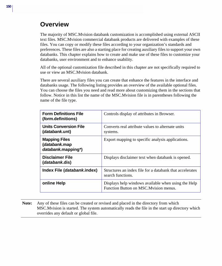
150
OverviewThe majority of MSC.Mvision databank customization is accomplished using external ASCII text files. MSC.Mvision commercial databank products are delivered with examples of these files. You can copy or modify these files according to your organization’s standards and preferences. These files are also a starting place for creating auxiliary files to support your own databanks. This chapter explains how to create and make use of these files to customize your databanks, user environment and to enhance usability.
All of the optional customization file described in this chapter are not specifically required to use or view an MSC.Mvision databank.
There are several auxiliary files you can create that enhance the features in the interface and databanks usage. The following listing provides an overview of the available optional files. You can choose the files you need and read more about customizing them in the sections that follow. Notice in this list the name of the MSC.Mvision file is in parentheses following the name of the file type.
Form Definitions File (form.definitions)
Controls display of attributes in Browser.
Units Conversion File (databank.unt)
Converts real attribute values to alternate units systems.
Mapping Files (databank.map databank.mapping*)
Export mapping to specific analysis applications.
Disclaimer File (databank.dis)
Displays disclaimer text when databank is opened.
Index File (databank.index) Structures an index file for a databank that accelerates search functions.
online Help Displays help windows available when using the Help Function Button on MSC.Mvision menus.
Note: Any of these files can be created or revised and placed in the directory from which MSC.Mvision is started. The system automatically reads the file in the start up directory which overrides any default or global file.
151CHAPTER 6Creating Customization Files
Form Definitions FileThe Form Definitions file provides a method of displaying different views of the same databank data. The form.definitions file is an MSC.Mvision interface configuration tool. The definition in a form file determines the default criteria definitions and categories that are displayed in the Browser interface. Depending on the user’s requirements, you can format the Materials Browser display to present specified data in a predetermined form or exclude data from the display.
A form.definitions file can:
• Include commonly used queries.
• Limit or subdivide the data into categories for independent display.
• Group related or unrelated data for display.
The form.defintions file gives you control over the way information is viewed and accessed in a databank.
MSC.Mvision automatically creates a default form for any databank when opened and you do not have any existing form. It is recommended that you create the form files for your databank interactively by customizing the default form in the user interface.
You can customize a default form or any form interactively, using the Edit menu options, or you can add definitions to the form.definitions file directly.
A form for a specific databank is typically created as a databank.mvform file and is compiled with the other available mvform file to create a complete form.definitions file which includes forms for all the available databanks. To accommodate this process, MSC.Mvision provides an mvform script in the install/bin directory.
Refer to the MSC.Mvision Builder and Evaluator User’s Guide and Reference for more information on mvform and form.definitions files.
Constructing the Form Definitions FileIf you are building databanks for various users, you may want to construct a custom form.definitions file to be made available along with the databanks so that the various users can view the same databank information in a different manner. You can create this file using a text editor, or you can use an existing form file and modify it.
Before constructing your form.definitions file, review information for form.definition files in the MSC.Mvision Builder and Evaluator User’s Guide and Reference.
The basic components of a form are illustrated in the example below and are described in detail in the information that follows. These basic components are required for each form.
To construct a custom form for your databank, follow the format and syntax described below.
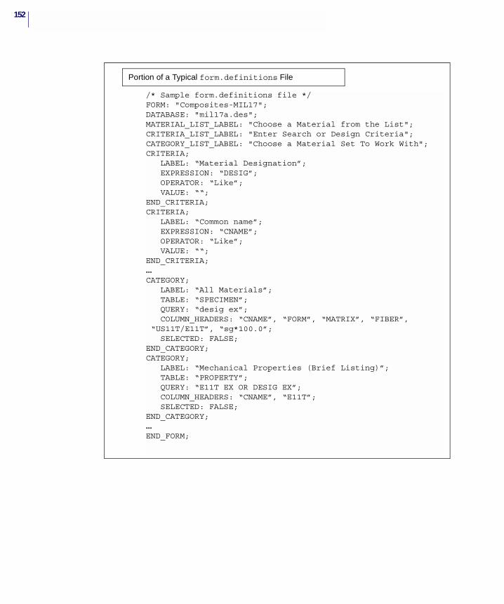
152
/* Sample form.definitions file */FORM: "Composites-MIL17";DATABASE: "mil17a.des";MATERIAL_LIST_LABEL: "Choose a Material from the List";CRITERIA_LIST_LABEL: "Enter Search or Design Criteria";CATEGORY_LIST_LABEL: "Choose a Material Set To Work With";CRITERIA;
LABEL: “Material Designation”; EXPRESSION: “DESIG”; OPERATOR: “Like”; VALUE: ““;
END_CRITERIA;CRITERIA;
LABEL: “Common name”; EXPRESSION: “CNAME”; OPERATOR: “Like”; VALUE: ““;
END_CRITERIA;...CATEGORY;
LABEL: “All Materials”; TABLE: “SPECIMEN”; QUERY: “desig ex”; COLUMN_HEADERS: “CNAME”, “FORM”, “MATRIX”, “FIBER”, “US11T/E11T”, “sg*100.0”; SELECTED: FALSE;
END_CATEGORY;CATEGORY;
LABEL: “Mechanical Properties (Brief Listing)”; TABLE: “PROPERTY”; QUERY: “E11T EX OR DESIG EX”; COLUMN_HEADERS: “CNAME”, “E11T”; SELECTED: FALSE;
END_CATEGORY;...END_FORM;
Portion of a Typical form.definitions File
153CHAPTER 6Creating Customization Files
The following sections lists the components of the previous example form.definitions file and includes an explanation of each:
FORM - Begins a new form definition and names the form. This name displays in the forms selection box in the Browser. Duplicate form names are not permitted.
DATABASE - Defines the specific databank name that the form applies to. The full path can be specified in the databank name to ensure that the form is attached to a specific databank version or location. For example, instead of
DATABASE: "mil17a.des";
as shown in the example, you can use “~/mil17a.des” to specify a version of the databank in the user’s home directory. When initiated, the system uses the defined name to search the mv_path.
MATERIAL_LIST_LABEL - Defines the text string displayed at the top of the material list in the Materials Browser.
CRITERIA_LIST_LABEL - Defines the text string displayed at the top of the criteria pane in the Materials Browser.
CATEGORY_LIST_LABEL - Defines the text string displayed at the top of the category pane in the Materials Browser.
CRITERIA - Begins the definition of a predetermined set of query criteria for use in the criteria list. When selected, a criteria button initiates a preset query. Each criteria definition contains:
LABEL - Defines the text of the criteria button.
EXPRESSION - Defines the databank expression typically an attribute name (E11T, E11T/2.0,) to be used in the query.
OPERATOR - Defines the operator (specify only one) to be used in the query. Attributes with scalar values use numeric operators: =, !=, >, <, >=, <=. Attributes with text values use “LIKE”, “NOT LIKE”, =(exact match) or !=.
VALUE - Defines the default value that the operator will use for the query. Typically this is null so that the user can enter his own value for the query.
End Criteria - Ends the definition of a criteria.
CATEGORY - Begins the definition of a material set (category). A category initiates and executes a query and configures the material list when selected. Each material set contains:
LABEL - Defines the text for the material set label displayed next to the radio button in the Materials Browser.
TABLE - Defines the databank relation for this material set. This parameter determine the relation level at which the following query applies. therefore if the query returns no rows at this relation level, nothing will be displayed. This also defines the initial
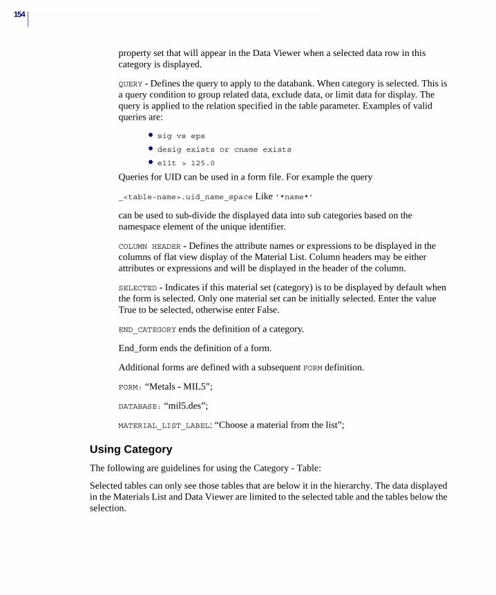
154
property set that will appear in the Data Viewer when a selected data row in this category is displayed.
QUERY - Defines the query to apply to the databank. When category is selected. This is a query condition to group related data, exclude data, or limit data for display. The query is applied to the relation specified in the table parameter. Examples of valid queries are:
• sig vs eps
• desig exists or cname exists
• e11t > 125.0
Queries for UID can be used in a form file. For example the query
_<table-name>.uid_name_space Like ’*name*’
can be used to sub-divide the displayed data into sub categories based on the namespace element of the unique identifier.
COLUMN HEADER - Defines the attribute names or expressions to be displayed in the columns of flat view display of the Material List. Column headers may be either attributes or expressions and will be displayed in the header of the column.
SELECTED - Indicates if this material set (category) is to be displayed by default when the form is selected. Only one material set can be initially selected. Enter the value True to be selected, otherwise enter False.
END_CATEGORY ends the definition of a category.
End_form ends the definition of a form.
Additional forms are defined with a subsequent FORM definition.
FORM: “Metals - MIL5”;
DATABASE: “mil5.des”;
MATERIAL_LIST_LABEL: “Choose a material from the list”;
Using Category
The following are guidelines for using the Category - Table:
Selected tables can only see those tables that are below it in the hierarchy. The data displayed in the Materials List and Data Viewer are limited to the selected table and the tables below the selection.
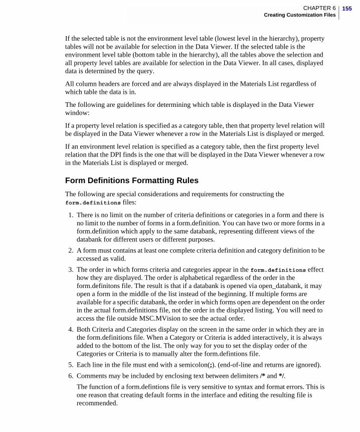
155CHAPTER 6Creating Customization Files
If the selected table is not the environment level table (lowest level in the hierarchy), property tables will not be available for selection in the Data Viewer. If the selected table is the environment level table (bottom table in the hierarchy), all the tables above the selection and all property level tables are available for selection in the Data Viewer. In all cases, displayed data is determined by the query.
All column headers are forced and are always displayed in the Materials List regardless of which table the data is in.
The following are guidelines for determining which table is displayed in the Data Viewer window:
If a property level relation is specified as a category table, then that property level relation will be displayed in the Data Viewer whenever a row in the Materials List is displayed or merged.
If an environment level relation is specified as a category table, then the first property level relation that the DPI finds is the one that will be displayed in the Data Viewer whenever a row in the Materials List is displayed or merged.
Form Definitions Formatting Rules
The following are special considerations and requirements for constructing the form.definitions files:
1. There is no limit on the number of criteria definitions or categories in a form and there is no limit to the number of forms in a form.definition. You can have two or more forms in a form.definition which apply to the same databank, representing different views of the databank for different users or different purposes.
2. A form must contains at least one complete criteria definition and category definition to be accessed as valid.
3. The order in which forms criteria and categories appear in the form.definitions effect how they are displayed. The order is alphabetical regardless of the order in the form.definitons file. The result is that if a databank is opened via open_databank, it may open a form in the middle of the list instead of the beginning. If multiple forms are available for a specific databank, the order in which forms open are dependent on the order in the actual form.definitions file, not the order in the displayed listing. You will need to access the file outside MSC.MVision to see the actual order.
4. Both Criteria and Categories display on the screen in the same order in which they are in the form.definitions file. When a Category or Criteria is added interactively, it is always added to the bottom of the list. The only way for you to set the display order of the Categories or Criteria is to manually alter the form.defintions file.
5. Each line in the file must end with a semicolon(;). (end-of-line and returns are ignored).
6. Comments may be included by enclosing text between delimiters /* and */.
The function of a form.defintions file is very sensitive to syntax and format errors. This is one reason that creating default forms in the interface and editing the resulting file is recommended.

156
Wildcard FormsEntering an asterisk (*), in the databank name parameter for the database line creates a wildcard form. The form name is not displayed until a databank is opened that matches the wildcard name. For example a databank named MIL5F.des opens a form with the database name:
“MIL5*.DES”
A wildcard form can be made path-independent. Wildcard forms are available in MSC.Mvision for special situations, but their general use is discouraged due to their unique behavior. In the interface the *name is replaced by the name of the databank to which it is attached and cannot be changed during a session. This name replacement is written to the settings file and will be maintained for subsequent sessions. The only way to change a wildcard form after it has been attached to a databank is to remove the setting file and restart or keep the form.definitons file which contains the wildcard form in your start-up directory, exit and restart MSC.Mvision and open a different databank that matches the form.
157CHAPTER 6Creating Customization Files
Units Conversion FileDatabank values are usually entered and stored in the units system in which they were tested. Since users may prefer or require a different unit system for viewing or export, the units conversion file is used to provide the MSC.Mvision application with the names of the different units systems and the names of the attributes to which conversion factors are to be applied for these alternate units systems.
When you build a new databank, you can provide for conversions for real number values to alternate units systems by constructing a units conversion file. Only real attributes are converted. Conversion of a value includes changing (replacing) the displayed units string for the attribute value.
For example, if your default units are in U.S. Customary engineering form, you may want to provide for conversion to SI Metric, or to U.S. Consistent (before exporting to an FEA application).
The units conversion file name must match the databank file name with the extension .unt. For example, name the file databank.unt, where databank is the same as the databank file name, e.g. databank.des. This is the MSC.Mvision databank for MIL-5 Handbook data called mil5.des and the units conversion file is mil5.unt.
When you open a databank, the system automatically looks for a units conversion file and reads the file storing the information for future reference.
A units conversion file consists of sets of named conversion parameters. The file contains one or more lists of attributes or their abbreviations along with a units string and a conversion factor that converts the default values to the alternate system units and replaces the displayed unit string.
The format and syntax of a units conversion file are described in the MSC.Mvision Builder and Evaluator User’s Guide and Reference. You may want to copy one of the units conversion files delivered with MSC.Mvision and modify it to apply to the attributes in your databank.

158
Mapping FilesExport templates can be created to format data for direct export to other software programs. Mapping files provide mapping of the attribute names in the databank to the entities required by the export template.
Various export templates and mapping files have been defined for controlling the export of data to external applications, such as MSC.Nastran, FEA Analysis code, CAD programs and various other applications. These mapping files are basically templates that associate MSC.Mvision attribute names with entities in the external application, along with any required data manipulation.
The format and syntax of the export templates and mapping files are described in detail in the MSC.Mvision Builder and Evaluator User’s Guide and Reference.
159CHAPTER 6Creating Customization Files
Disclaimer FileThe disclaimer file provides information about the current databank and is displayed every time the databank is opened. It is often used as a Help window or a notice panel. If a disclaimer is not available for a databank when it is opened, MSC.Mvision opens a default disclaimer file located in the $MV_PATH/ resources directory.
A disclaimer file is a text file. The only unique thing about this file is the file name. The filename must be databank.dis, where databank is the databank to which it applies. For example, MIL5.dis is a disclaimer for the MIL5.des databank. A disclaimer file can be located and read from the current directory, but is typically maintained in the same directory as the databank.
A disclaimer file typically includes:
• Brief description of the contents
• Release or version identifier
• Date of release or latest modification
• Author or sponsoring organization
• Classification or security status
• Data quality indicators
160
Index FileAn MSC.Mvision index file is a binary file that contains a constructed representation of the databank. Data access and query function performance may be improved significantly by using an index file.
An index file can only be created from within MSC.Mvision using the File - Builder Functions - Index option for an open databank or by using the mvindex command line function.
For Unix/Linux:
mvindex databank_name
For Windows:
mvindex.bat databank_name
A file named databank.index is created in the current directory. When the databank structure is changed, you will have to recreate the index file. The system reports “Index file is incompatible” when the index file does not match the databank structure.
An index file is not required, but highly recommended. The system automatically searches for and reads the index file when a databank is opened. The index file can be located in the start-up directory, but is typically located in the same directory as the databank.

161CHAPTER 6Creating Customization Files
Online HelpIn MSC.Mvision, a Help button is located on most windows in either the upper right corner or along the bottom of the window. Select the Help button to display a list of help functions similar to the following example. To create customized help files, refer to online help “On This Databank" in the help menu button.

162

MSC.Mvision Builder and Evaluator 2002 Installation Guide
A Building Databanks
� Builder Functions
� Building Databanks - Tutorial
164
Builder FunctionsThe Builder Functions section of this appendix is organized in order as the following options are listed on the Builder Function menu:
• New Databank
• Read Data
• Write Data
• Write Databank
• Save Databank
• Save Databank As
• Edit Attributes
• Add Attributes
• Data Editor
• Delete Row
• List Attributes
• Index Databank
• SessionFile Playback
• Create Builder Log File
• Show All Builder Messages
• Show Summary Build Messages
A brief explanation of each function and reference to detailed information is provided in this section.
You can access these functions in the Materials Browser by selecting File - Builder Functions. After the Builder Functions menu displays, select the option.
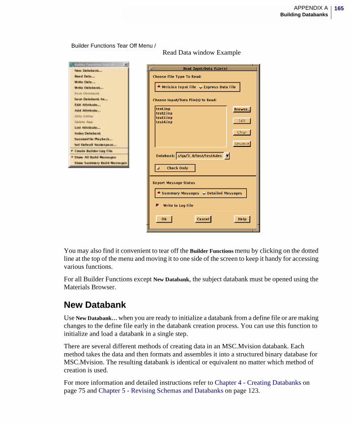
165APPENDIX ABuilding Databanks
You may also find it convenient to tear off the Builder Functions menu by clicking on the dotted line at the top of the menu and moving it to one side of the screen to keep it handy for accessing various functions.
For all Builder Functions except New Databank, the subject databank must be opened using the Materials Browser.
New Databank Use New Databank… when you are ready to initialize a databank from a define file or are making changes to the define file early in the databank creation process. You can use this function to initialize and load a databank in a single step.
There are several different methods of creating data in an MSC.Mvision databank. Each method takes the data and then formats and assembles it into a structured binary database for MSC.Mvision. The resulting databank is identical or equivalent no matter which method of creation is used.
For more information and detailed instructions refer to Chapter 4 - Creating Databanks on page 75 and Chapter 5 - Revising Schemas and Databanks on page 123.
Builder Functions Tear Off Menu /Read Data window Example
166
Read DataUse Read Data when you are ready to load data into an existing databank or are making changes to the databank. Note that the same function can be performed as part of creating a new databank. To use this function, first you need a databank and an input file or EXPRESS data file.
For more information and instructions refer to Chapter 4 - Creating Databanks on page 75 and Chapter 5 - Revising Schemas and Databanks on page 123.
Write Data / Write Databank…
Use Write Data / Write Databank… when you want to write MSC.Mvision define or input files or EXPRESS schema or data files from either a part or an entire databank.
This function may be useful for:
• Transferring databanks to incompatible platforms.
• Exporting data to other applications.
• Cleaning up and rebuilding parts of a databank.
For more information and instructions refer to Chapter 5 - Revising Schemas and Databanks on page 123.
Save Databank / Save Databank As…
While you are using the databank building process, it is a good idea to save your databank at regular intervals, particularly if you are making extensive or complicated modifications.
The Save Databank function saves the current version of the open databank to a file of the same name.
To save a databank using a different name, choose the Save Databank As… option. This option saves the latest version of the currently open databank using an alternate file name.
When you are ready to save the new or modified databank, select File - Builder Functions - Save Databank (or Save Databank As…) from the Browser window.
For more information and instructions refer to the section Saving Databanks on page 120 in Chapter 4.
Modifying a DatabankThe Builder Functions menu features several functions useful for modifying existing databanks:
• Edit Attributes…, Add Attributes…, and List Attributes… allow you to modify attribute definitions, add attributes to any level of the hierarchy or to a data relation. add data relations or review the attributes currently defined in the databank.
167APPENDIX ABuilding Databanks
• Data Editor… allows you to modify the databank values on a table by table basis.
• Delete Row allows you to delete selected data rows from an existing databank.
Note: After a databank is created, the databank hierarchy is fixed and you cannot modify it. To add a hierarchy level to the databank or to otherwise modify the hierarchy you must rebuild the entire databank.
For more information and instructions refer to Chapter 5 - Revising Schemas and Databanks on page 123.
Edit Attributes…
The Edit Attributes… option allows you to modify the parameters of an attribute definition in the current databank.
After selecting an attribute, the current definition is displayed in the Edit Attribute window, with the editable components displayed in cells where you can select and modify the values.
For more information and instructions refer to Chapter 5, the section, Reviewing and Revising Schemas on page 125.
Add Attributes…
The Add Attributes… option allows you to add new attributes to the relations of an existing databank. You can also add a new attribute with a new data relation using this function.
For more information and instructions refer to Chapter 5, the section, Reviewing and Revising Schemas on page 125.
Set Default Namespace…
The Set Default Namespace… option allows you to change the default name space that will be used to create UID’s in the databank. A listing of currently used namespaces is shown to help you with your decision.
For more information and instructions refer to Chapter 5, the section, Reviewing and Revising Schemas on page 125.
List Attributes…
The List Attributes… option allows you to review attribute parameters by displaying a listing of the attribute definitions in the current databank. The information includes the attribute name, description, units, precision, relation assigned, and data type.
For more information and instructions refer to Chapter 5 - Reviewing and Revising Schemas on page 125.
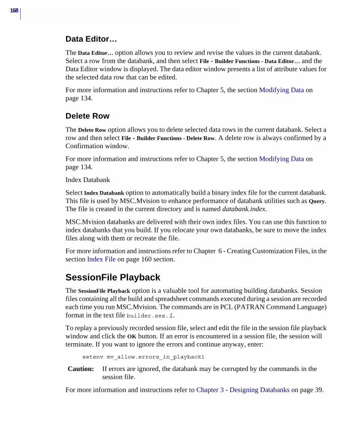
168
Data Editor…
The Data Editor… option allows you to review and revise the values in the current databank. Select a row from the databank, and then select File - Builder Functions - Data Editor… and the Data Editor window is displayed. The data editor window presents a list of attribute values for the selected data row that can be edited.
For more information and instructions refer to Chapter 5, the section Modifying Data on page 134.
Delete Row
The Delete Row option allows you to delete selected data rows in the current databank. Select a row and then select File - Builder Functions - Delete Row. A delete row is always confirmed by a Confirmation window.
For more information and instructions refer to Chapter 5, the section Modifying Data on page 134.
Index Databank
Select Index Databank option to automatically build a binary index file for the current databank. This file is used by MSC.Mvision to enhance performance of databank utilities such as Query. The file is created in the current directory and is named databank.index.
MSC.Mvision databanks are delivered with their own index files. You can use this function to index databanks that you build. If you relocate your own databanks, be sure to move the index files along with them or recreate the file.
For more information and instructions refer to Chapter 6 - Creating Customization Files, in the section Index File on page 160 section.
SessionFile PlaybackThe SessionFile Playback option is a valuable tool for automating building databanks. Session files containing all the build and spreadsheet commands executed during a session are recorded each time you run MSC.Mvision. The commands are in PCL (PATRAN Command Language) format in the text file builder.ses.i.
To replay a previously recorded session file, select and edit the file in the session file playback window and click the OK button. If an error is encountered in a session file, the session will terminate. If you want to ignore the errors and continue anyway, enter:
setenv mv_allow.errors_in_playback1
Caution: If errors are ignored, the databank may be corrupted by the commands in the session file.
For more information and instructions refer to Chapter 3 - Designing Databanks on page 39.

169APPENDIX ABuilding Databanks
Log FilesThe Create Builder Log File option saves all messages produced during a Builder Functions operation or a spreadsheet session to be written in a log file. These include information, warning, and error messages. The file is written to the current directory with the default name of builder.log.i.
Show All Build Messages/Show Summary Build Messages
The Build Messages options are toggles. Show All displays all messages produced, except the system, to the status window. Show Summary displays a condensed version of build messages in the status window. All build messages returned to the status window can be written to the log file.
For more information and instructions refer to Chapter 4, the section Data Loading Methods on page 90.
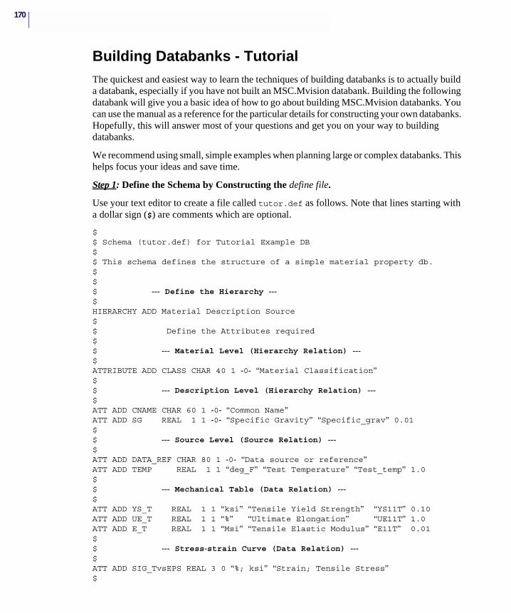
170
Building Databanks - TutorialThe quickest and easiest way to learn the techniques of building databanks is to actually build a databank, especially if you have not built an MSC.Mvision databank. Building the following databank will give you a basic idea of how to go about building MSC.Mvision databanks. You can use the manual as a reference for the particular details for constructing your own databanks. Hopefully, this will answer most of your questions and get you on your way to building databanks.
We recommend using small, simple examples when planning large or complex databanks. This helps focus your ideas and save time.
Step 1: Define the Schema by Constructing the define file.
Use your text editor to create a file called tutor.def as follows. Note that lines starting with a dollar sign ($) are comments which are optional.
$$ Schema (tutor.def) for Tutorial Example DB$$ This schema defines the structure of a simple material property db.$$$ --- Define the Hierarchy ---$HIERARCHY ADD Material Description Source$$ Define the Attributes required$$ --- Material Level (Hierarchy Relation) ---$ATTRIBUTE ADD CLASS CHAR 40 1 -0- “Material Classification”$$ --- Description Level (Hierarchy Relation) ---$ATT ADD CNAME CHAR 60 1 -0- “Common Name”ATT ADD SG REAL 1 1 -0- “Specific Gravity” “Specific_grav” 0.01$$ --- Source Level (Source Relation) ---$ATT ADD DATA_REF CHAR 80 1 -0- “Data source or reference” ATT ADD TEMP REAL 1 1 “deg_F” “Test Temperature” “Test_temp” 1.0$$ --- Mechanical Table (Data Relation) ---$ATT ADD YS_T REAL 1 1 “ksi” “Tensile Yield Strength” “YS11T” 0.10ATT ADD UE_T REAL 1 1 “%” “Ultimate Elongation” “UE11T” 1.0ATT ADD E_T REAL 1 1 “Msi” “Tensile Elastic Modulus” “E11T” 0.01$$ --- Stress-strain Curve (Data Relation) ---$ATT ADD SIG_TvsEPS REAL 3 0 “%; ksi” “Strain; Tensile Stress”$
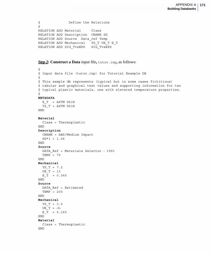
171APPENDIX ABuilding Databanks
$ Define the Relations$RELATION ADD Material ClassRELATION ADD Description CNAME SGRELATION ADD Source Data_ref TempRELATION ADD Mechanical YS_T UE_T E_TRELATION ADD SIG_TvsEPS SIG_TvsEPS
Step 2: Construct a Data input file, tutor.inp, as follows:
$$ Input data file (tutor.inp) for Tutorial Example DB$$ This sample db represents (typical but in some cases fictitious)$ tabular and graphical test values and supporting information for two$ typical plastic materials, one with elevated temperature properties.$METADATA E_T = ASTM D638 YS_T = ASTM D638END
Material Class = ThermoplasticENDDescription CNAME = ABS/Medium Impact SG*1 = 1.06ENDSource DATA_Ref = Materials Selector - 1991 TEMP = 70ENDMechanical YS_T = 7.2 UE_T = 13 E_T = 0.365ENDSource DATA_Ref = Estimated TEMP = 200ENDMechanical YS_T = 3.0 UE_T = -0- E_T = 0.160ENDMaterial Class = ThermoplasticEND
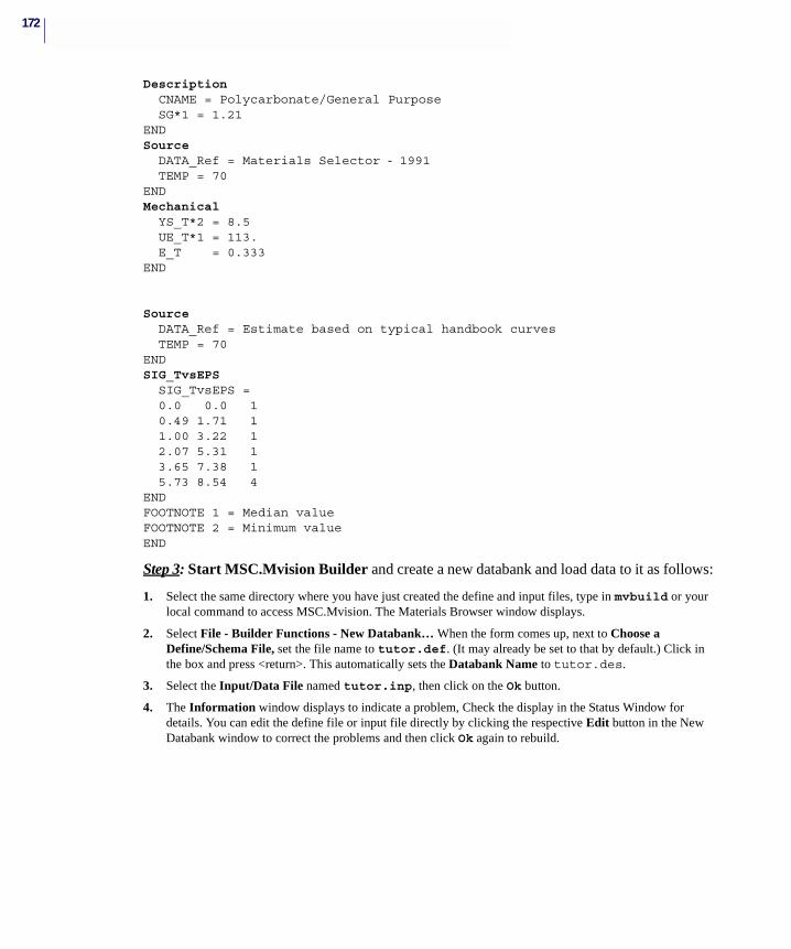
172
Description CNAME = Polycarbonate/General Purpose SG*1 = 1.21ENDSource DATA_Ref = Materials Selector - 1991 TEMP = 70ENDMechanical YS_T*2 = 8.5 UE_T*1 = 113. E_T = 0.333END
Source DATA_Ref = Estimate based on typical handbook curves TEMP = 70ENDSIG_TvsEPS SIG_TvsEPS = 0.0 0.0 1 0.49 1.71 1 1.00 3.22 1 2.07 5.31 1 3.65 7.38 1 5.73 8.54 4ENDFOOTNOTE 1 = Median valueFOOTNOTE 2 = Minimum valueEND
Step 3: Start MSC.Mvision Builder and create a new databank and load data to it as follows:
1. Select the same directory where you have just created the define and input files, type in mvbuild or your local command to access MSC.Mvision. The Materials Browser window displays.
2. Select File - Builder Functions - New Databank… When the form comes up, next to Choose a Define/Schema File, set the file name to tutor.def. (It may already be set to that by default.) Click in the box and press <return>. This automatically sets the Databank Name to tutor.des.
3. Select the Input/Data File named tutor.inp, then click on the Ok button.
4. The Information window displays to indicate a problem, Check the display in the Status Window for details. You can edit the define file or input file directly by clicking the respective Edit button in the New Databank window to correct the problems and then click Ok again to rebuild.
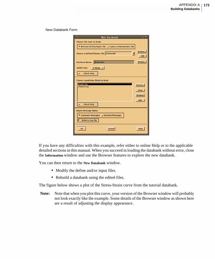
173APPENDIX ABuilding Databanks
If you have any difficulties with this example, refer either to online Help or to the applicable detailed sections in this manual. When you succeed in loading the databank without error, close the Information window and use the Browser features to explore the new databank.
You can then return to the New Databank window.
• Modify the define and/or input files.
• Rebuild a databank using the edited files.
The figure below shows a plot of the Stress-Strain curve from the tutorial databank.
Note: Note that when you plot this curve, your version of the Browser window will probably not look exactly like the example. Some details of the Browser window as shown here are a result of adjusting the display appearance.
New Databank Form
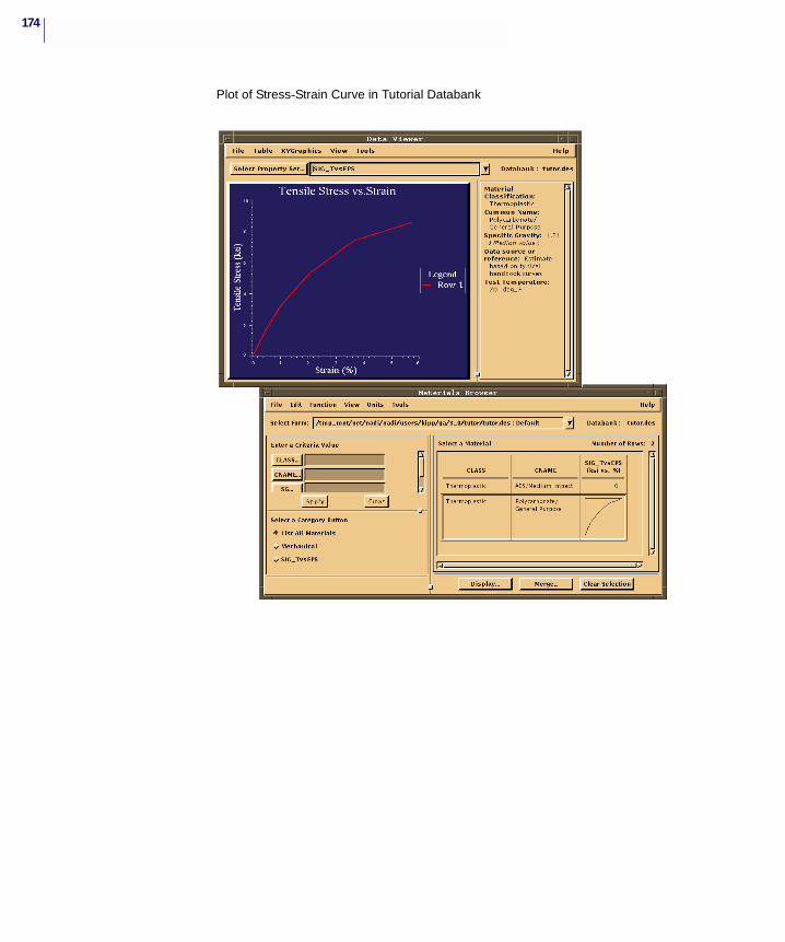
174
Plot of Stress-Strain Curve in Tutorial Databank

MSC.Mvision Builder and Evaluator 2002 Installation Guide
B Batch Builder Programs
� Batch Builder Programs
� MSC.Mvision PCL Commands
� DPI Functions
� EXPRESS Translators
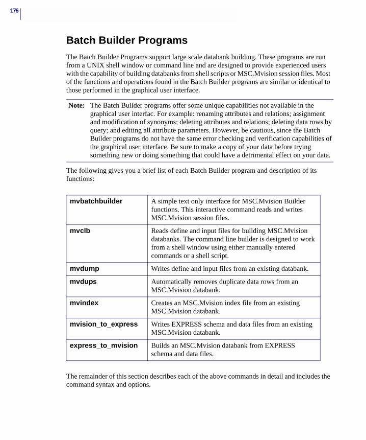
176
Batch Builder ProgramsThe Batch Builder Programs support large scale databank building. These programs are run from a UNIX shell window or command line and are designed to provide experienced users with the capability of building databanks from shell scripts or MSC.Mvision session files. Most of the functions and operations found in the Batch Builder programs are similar or identical to those performed in the graphical user interface.
The following gives you a brief list of each Batch Builder program and description of its functions:
The remainder of this section describes each of the above commands in detail and includes the command syntax and options.
Note: The Batch Builder programs offer some unique capabilities not available in the graphical user interfac. For example: renaming attributes and relations; assignment and modification of synonyms; deleting attributes and relations; deleting data rows by query; and editing all attribute parameters. However, be cautious, since the Batch Builder programs do not have the same error checking and verification capabilities of the graphical user interface. Be sure to make a copy of your data before trying something new or doing something that could have a detrimental effect on your data.
mvbatchbuilder A simple text only interface for MSC.Mvision Builder functions. This interactive command reads and writes MSC.Mvision session files.
mvclb Reads define and input files for building MSC.Mvision databanks. The command line builder is designed to work from a shell window using either manually entered commands or a shell script.
mvdump Writes define and input files from an existing databank.
mvdups Automatically removes duplicate data rows from an MSC.Mvision databank.
mvindex Creates an MSC.Mvision index file from an existing MSC.Mvision databank.
mvision_to_express Writes EXPRESS schema and data files from an existing MSC.Mvision databank.
express_to_mvision Builds an MSC.Mvision databank from EXPRESS schema and data files.
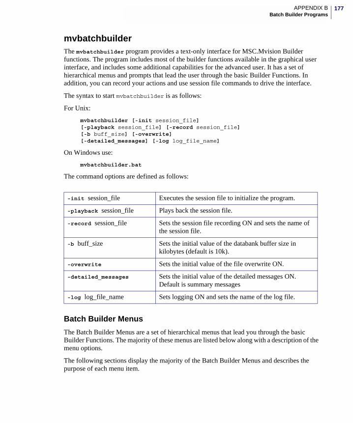
177APPENDIX BBatch Builder Programs
mvbatchbuilderThe mvbatchbuilder program provides a text-only interface for MSC.Mvision Builder functions. The program includes most of the builder functions available in the graphical user interface, and includes some additional capabilities for the advanced user. It has a set of hierarchical menus and prompts that lead the user through the basic Builder Functions. In addition, you can record your actions and use session file commands to drive the interface.
The syntax to start mvbatchbuilder is as follows:
For Unix:
mvbatchbuilder [-init session_file] [-playback session_file] [-record session_file] [-b buff_size] [-overwrite] [-detailed_messages] [-log log_file_name]
On Windows use:
mvbatchbuilder.bat
The command options are defined as follows:
Batch Builder Menus
The Batch Builder Menus are a set of hierarchical menus that lead you through the basic Builder Functions. The majority of these menus are listed below along with a description of the menu options.
The following sections display the majority of the Batch Builder Menus and describes the purpose of each menu item.
-init session_file Executes the session file to initialize the program.
-playback session_file Plays back the session file.
-record session_file Sets the session file recording ON and sets the name of the session file.
-b buff_size Sets the initial value of the databank buffer size in kilobytes (default is 10k).
-overwrite Sets the initial value of the file overwrite ON.
-detailed_messages Sets the initial value of the detailed messages ON. Default is summary messages
-log log_file_name Sets logging ON and sets the name of the log file.
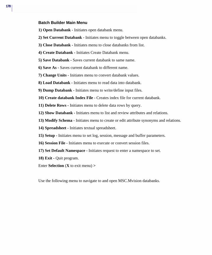
178
Batch Builder Main Menu
1) Open Databank - Initiates open databank menu.
2) Set Current Databank - Initiates menu to toggle between open databanks.
3) Close Databank - Initiates menu to close databanks from list.
4) Create Databank - Initiates Create Databank menu.
5) Save Databank - Saves current databank to same name.
6) Save As - Saves current databank to different name.
7) Change Units - Initiates menu to convert databank values.
8) Load Databank - Initiates menu to read data into databank.
9) Dump Databank - Initiates menu to write/define input files.
10) Create databank Index File - Creates index file for current databank.
11) Delete Rows - Initiates menu to delete data rows by query.
12) Show Databank - Initiates menu to list and review attributes and relations.
13) Modify Schema - Initiates menu to create or edit attribute synonyms and relations.
14) Spreadsheet - Initiates textual spreadsheet.
15) Setup - Initiates menu to set log, session, message and buffer parameters.
16) Session File - Initiates menu to execute or convert session files.
17) Set Default Namespace - Initiates request to enter a namespace to set.
18) Exit - Quit program.
Enter Selection (X to exit menu) >
Use the following menu to navigate to and open MSC.Mvision databanks.
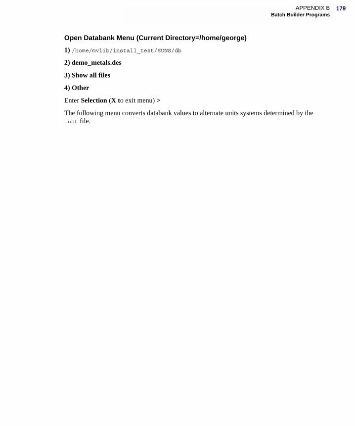
179APPENDIX BBatch Builder Programs
Open Databank Menu (Current Directory=/home/george)
1) /home/mvlib/install_test/SUNS/db
2) demo_metals.des
3) Show all files
4) Other
Enter Selection (X to exit menu) >
The following menu converts databank values to alternate units systems determined by the .unt file.
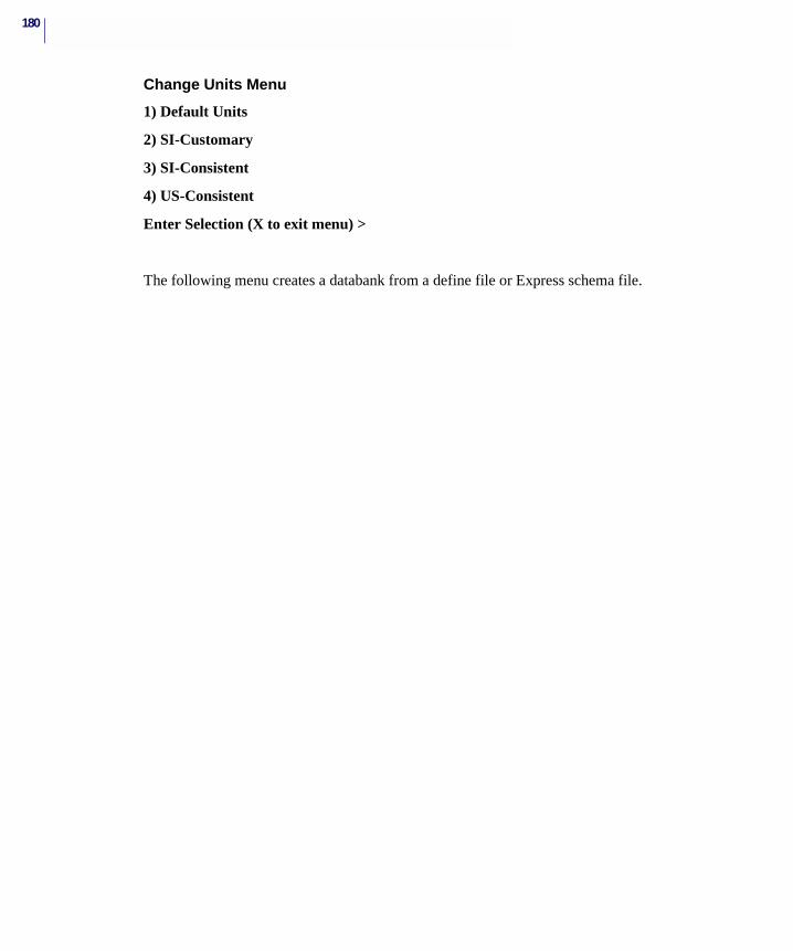
180
Change Units Menu
1) Default Units
2) SI-Customary
3) SI-Consistent
4) US-Consistent
Enter Selection (X to exit menu) >
The following menu creates a databank from a define file or Express schema file.
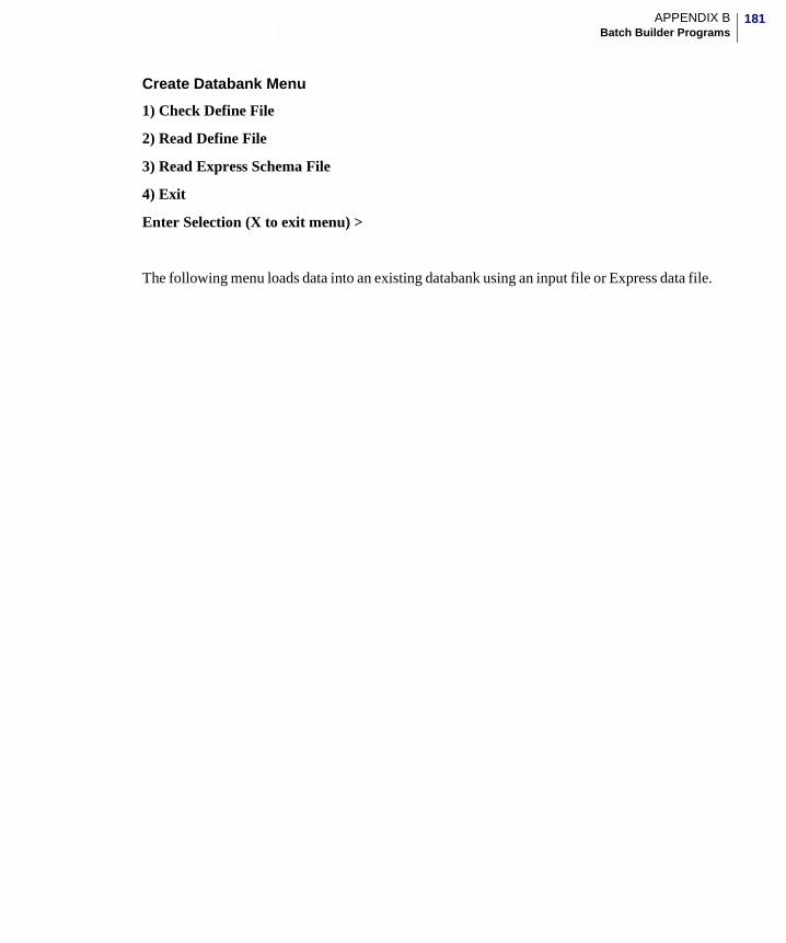
181APPENDIX BBatch Builder Programs
Create Databank Menu
1) Check Define File
2) Read Define File
3) Read Express Schema File
4) Exit
Enter Selection (X to exit menu) >
The following menu loads data into an existing databank using an input file or Express data file.
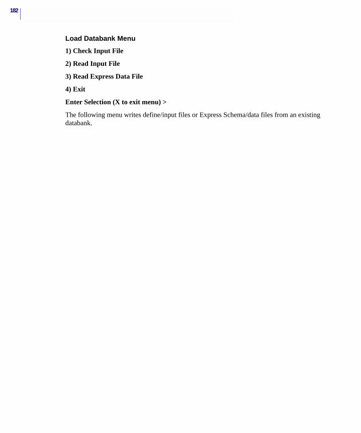
182
Load Databank Menu
1) Check Input File
2) Read Input File
3) Read Express Data File
4) Exit
Enter Selection (X to exit menu) >
The following menu writes define/input files or Express Schema/data files from an existing databank.
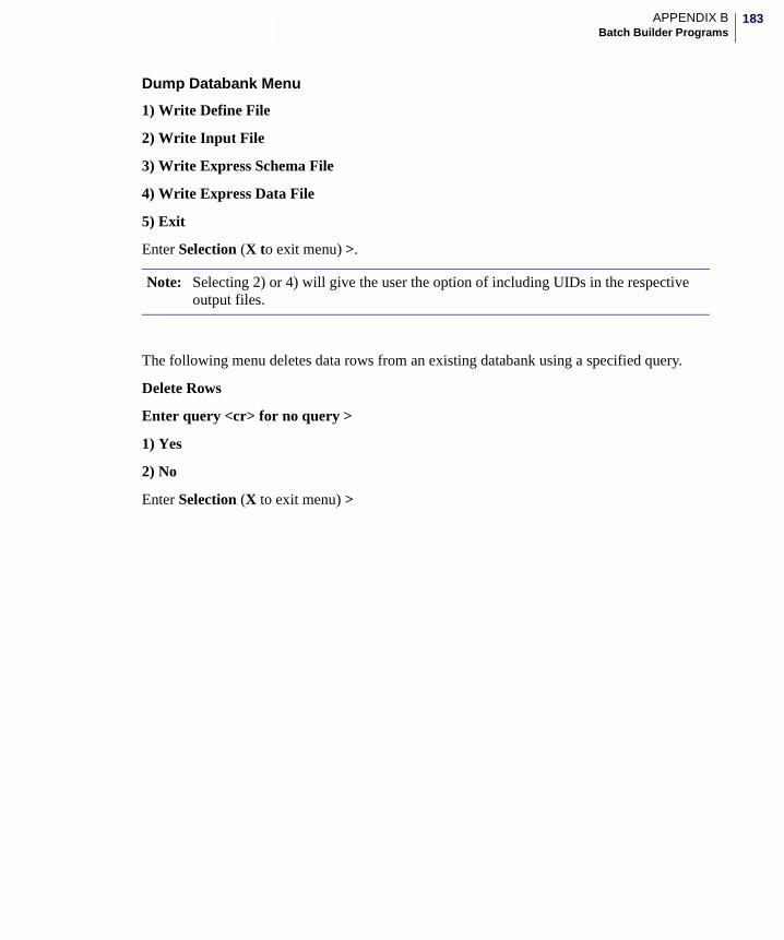
183APPENDIX BBatch Builder Programs
Dump Databank Menu
1) Write Define File
2) Write Input File
3) Write Express Schema File
4) Write Express Data File
5) Exit
Enter Selection (X to exit menu) >.
The following menu deletes data rows from an existing databank using a specified query.
Delete Rows
Enter query <cr> for no query >
1) Yes
2) No
Enter Selection (X to exit menu) >
Note: Selecting 2) or 4) will give the user the option of including UIDs in the respective output files.
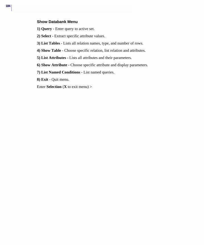
184
Show Databank Menu
1) Query - Enter query to active set.
2) Select - Extract specific attribute values.
3) List Tables - Lists all relation names, type, and number of rows.
4) Show Table - Choose specific relation, list relation and attributes.
5) List Attributes - Lists all attributes and their parameters.
6) Show Attribute - Choose specific attribute and display parameters.
7) List Named Conditions - List named queries.
8) Exit - Quit menu.
Enter Selection (X to exit menu) >
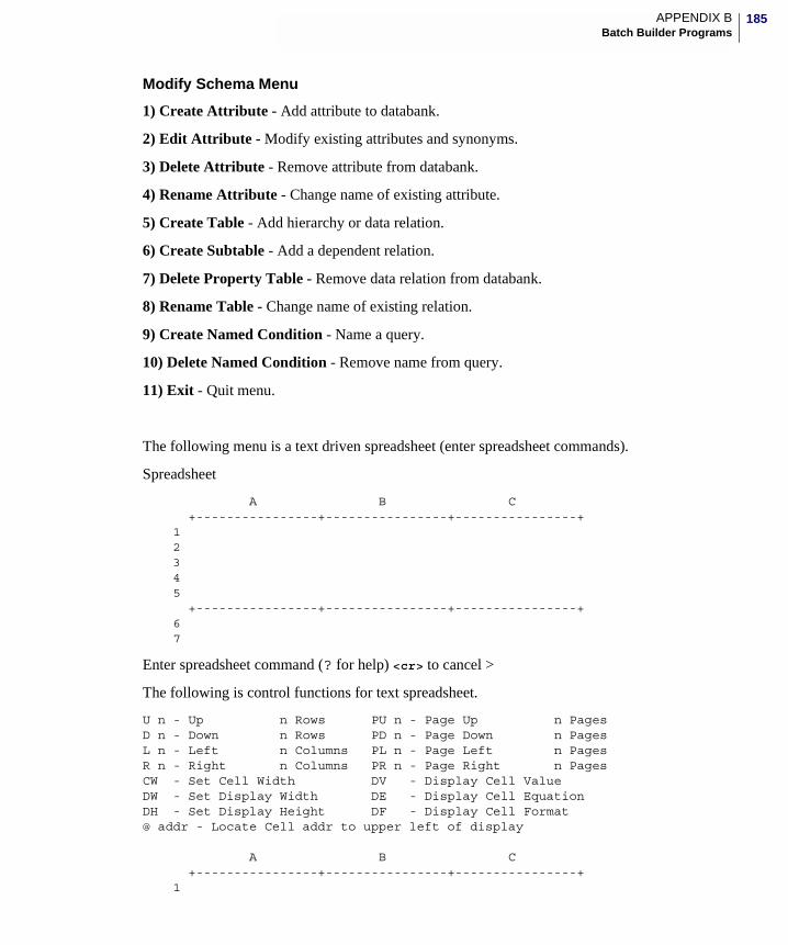
185APPENDIX BBatch Builder Programs
Modify Schema Menu
1) Create Attribute - Add attribute to databank.
2) Edit Attribute - Modify existing attributes and synonyms.
3) Delete Attribute - Remove attribute from databank.
4) Rename Attribute - Change name of existing attribute.
5) Create Table - Add hierarchy or data relation.
6) Create Subtable - Add a dependent relation.
7) Delete Property Table - Remove data relation from databank.
8) Rename Table - Change name of existing relation.
9) Create Named Condition - Name a query.
10) Delete Named Condition - Remove name from query.
11) Exit - Quit menu.
The following menu is a text driven spreadsheet (enter spreadsheet commands).
Spreadsheet
A B C +----------------+----------------+----------------+ 1 2 3 4 5 +----------------+----------------+----------------+ 6 7
Enter spreadsheet command (? for help) <cr> to cancel >
The following is control functions for text spreadsheet.
U n - Up n Rows PU n - Page Up n PagesD n - Down n Rows PD n - Page Down n PagesL n - Left n Columns PL n - Page Left n PagesR n - Right n Columns PR n - Page Right n PagesCW - Set Cell Width DV - Display Cell ValueDW - Set Display Width DE - Display Cell EquationDH - Set Display Height DF - Display Cell Format@ addr - Locate Cell addr to upper left of display A B C +----------------+----------------+----------------+ 1

186
2 3 4 5 +----------------+----------------+----------------+ 6 7
Enter spreadsheet command (? for help) <cr> to cancel >
The following menu sets up and controls recording and logging functions:
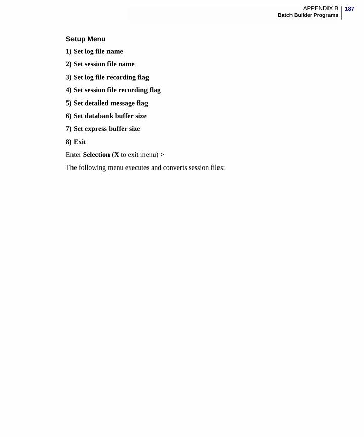
187APPENDIX BBatch Builder Programs
Setup Menu
1) Set log file name
2) Set session file name
3) Set log file recording flag
4) Set session file recording flag
5) Set detailed message flag
6) Set databank buffer size
7) Set express buffer size
8) Exit
Enter Selection (X to exit menu) >
The following menu executes and converts session files:
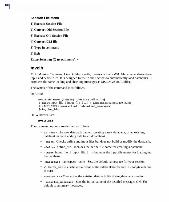
188
Session File Menu
1) Execute Session File
2) Convert Old Session File
3) Execute Old Session File
4) Convert CLI file
5) Type in command
6) Exit
Enter Selection (X to exit menu) >
mvclbMSC.Mvision Command Line Builder, mvclb, creates or loads MSC.Mvision databanks from input and define files. It is designed to use in shell scripts to automatically load databanks. It produces the same loading and checking messages as MSC.Mvision Builder.
The syntax of the command is as follows.
On Unix:
mvclb db_name [-check] [-define define_file] [-input input_file_1 input_file_2 …] [-namespace namespace_name] [-b buff_size] [-overwrite] [-detailed_messages] [-log log_file]
On Windows use:
mvclb.bat
The command options are defined as follows:
• db_name - The new databank name if creating a new databank, or an existing databank name if adding data to a old databank.
• -check - Checks define and input files but does not build or modify the databank.
• -define define_file - Includes the define file name for creating a databank.
• -input input_file_1 input_file_2… - Includes the input file names for loading into the databank.
• -namespace namespace_name - Sets the default namespace for your session.
• -b buffer_size - Sets the initial value of the databank buffer size in kilobytes (default is 10k).
• -overwrite - Overwrites the existing databank file during databank creation.
• -detailed_messages - Sets the initial value of the detailed messages ON. The default is summary messages.
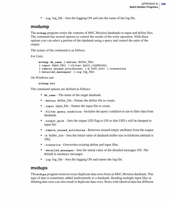
189APPENDIX BBatch Builder Programs
• -log log_file - Sets the logging ON and sets the name of the log file.
mvdumpThe mvdump program writes the contents of MSC.Mvision databanks to input and define files. The command has several options to control the results of the write operation. With these options you can select a portion of the databank using a query and control the units of the output.
The syntax of the command is as follows.
For Unix:
mvdump db_name [-define define_file] [-input input_file] [-filter query_conditions] [-remove_unused_attributes] [-b buff_size] [-overwrite] [-detailed_messages] [-log log_file]
On Windows use:
mvdump.bat
The command options are defined as follows:
• db_name - The name of the target databank.
• -define define_file - Names the define file to create.
• -input input_file - Names the input file to create.
• -filter query_condition - Includes the query condition to use to filter data from databank.
• -output_guid - Sets the output UID flag to ON so that UID’s will be dumped to input file.
• -remove_unused_attributes - Removes unused empty attributes from the output.
• -b buffer_size - Sets the initial value of databank buffer size in kilobytes (default is 10k).
• -overwrite - Overwrites existing define and input files.
• -detailed_messages - Sets the initial value of the detailed messages ON. The default is summary messages.
• -log log_file - Sets the logging ON and names the log file.
mvdupsThe mvdups program removes exact duplicate data rows from an MSC.Mvision databank. This type of data is sometimes added inadvertently to a databank. Reading multiple input files or deleting data rows can also result in duplicate data rows. Rows with identical data but different
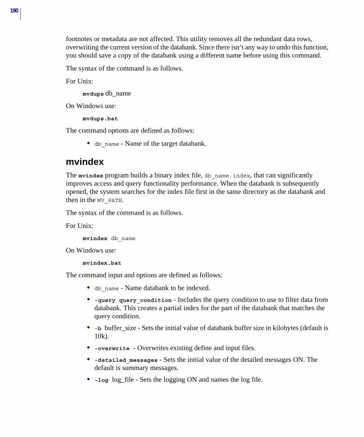
190
footnotes or metadata are not affected. This utility removes all the redundant data rows, overwriting the current version of the databank. Since there isn’t any way to undo this function, you should save a copy of the databank using a different name before using this command.
The syntax of the command is as follows.
For Unix:
mvdups db_name
On Windows use:
mvdups.bat
The command options are defined as follows:
• db_name - Name of the target databank.
mvindexThe mvindex program builds a binary index file, db_name.index, that can significantly improves access and query functionality performance. When the databank is subsequently opened, the system searches for the index file first in the same directory as the databank and then in the MV_PATH.
The syntax of the command is as follows.
For Unix:
mvindex db_name
On Windows use:
mvindex.bat
The command input and options are defined as follows:
• db_name - Name databank to be indexed.
• -query query_condition - Includes the query condition to use to filter data from databank. This creates a partial index for the part of the databank that matches the query condition.
• -b buffer_size - Sets the initial value of databank buffer size in kilobytes (default is 10k).
• -overwrite - Overwrites existing define and input files.
• -detailed_messages - Sets the initial value of the detailed messages ON. The default is summary messages.
• -log log_file - Sets the logging ON and names the log file.
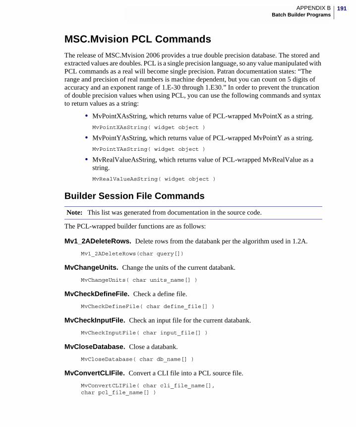
191APPENDIX BBatch Builder Programs
MSC.Mvision PCL CommandsThe release of MSC.Mvision 2006 provides a true double precision database. The stored and extracted values are doubles. PCL is a single precision language, so any value manipulated with PCL commands as a real will become single precision. Patran documentation states: “The range and precision of real numbers is machine dependent, but you can count on 5 digits of accuracy and an exponent range of 1.E-30 through 1.E30.” In order to prevent the truncation of double precision values when using PCL, you can use the following commands and syntax to return values as a string:
• MvPointXAsString, which returns value of PCL-wrapped MvPointX as a string.
MvPointXAsString( widget object )
• MvPointYAsString, which returns value of PCL-wrapped MvPointY as a string.
MvPointYAsString( widget object )
• MvRealValueAsString, which returns value of PCL-wrapped MvRealValue as a string.
MvRealValueAsString( widget object )
Builder Session File Commands
The PCL-wrapped builder functions are as follows:
Mv1_2ADeleteRows. Delete rows from the databank per the algorithm used in 1.2A.
Mv1_2ADeleteRows(char query[])
MvChangeUnits. Change the units of the current databank.
MvChangeUnits( char units_name[] )
MvCheckDefineFile. Check a define file.
MvCheckDefineFile( char define_file[] )
MvCheckInputFile. Check an input file for the current databank.
MvCheckInputFile( char input_file[] )
MvCloseDatabase. Close a databank.
MvCloseDatabase( char db_name[] )
MvConvertCLIFile. Convert a CLI file into a PCL source file.
MvConvertCLIFile( char cli_file_name[], char pcl_file_name[] )
Note: This list was generated from documentation in the source code.
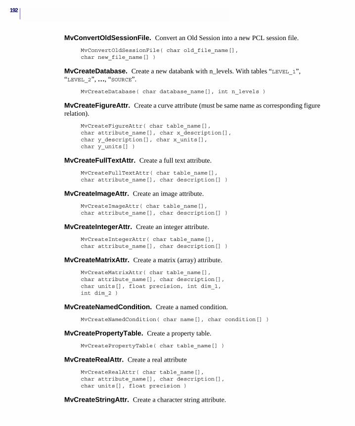
192
MvConvertOldSessionFile. Convert an Old Session into a new PCL session file.
MvConvertOldSessionFile( char old_file_name[], char new_file_name[] )
MvCreateDatabase. Create a new databank with n_levels. With tables “LEVEL_1”, “LEVEL_2”, …, “SOURCE”.
MvCreateDatabase( char database_name[], int n_levels )
MvCreateFigureAttr. Create a curve attribute (must be same name as corresponding figure relation).
MvCreateFigureAttr( char table_name[], char attribute_name[], char x_description[], char y_description[], char x_units[],char y_units[] )
MvCreateFullTextAttr. Create a full text attribute.
MvCreateFullTextAttr( char table_name[], char attribute_name[], char description[] )
MvCreateImageAttr. Create an image attribute.
MvCreateImageAttr( char table_name[], char attribute_name[], char description[] )
MvCreateIntegerAttr. Create an integer attribute.
MvCreateIntegerAttr( char table_name[], char attribute_name[], char description[] )
MvCreateMatrixAttr. Create a matrix (array) attribute.
MvCreateMatrixAttr( char table_name[], char attribute_name[], char description[], char units[], float precision, int dim_1, int dim_2 )
MvCreateNamedCondition. Create a named condition.
MvCreateNamedCondition( char name[], char condition[] )
MvCreatePropertyTable. Create a property table.
MvCreatePropertyTable( char table_name[] )
MvCreateRealAttr. Create a real attribute
MvCreateRealAttr( char table_name[], char attribute_name[], char description[], char units[], float precision )
MvCreateStringAttr. Create a character string attribute.

193APPENDIX BBatch Builder Programs
MvCreateStringAttr( char table_name[], char attribute_name[], char description[], int width )
MvCreateSynonym. Create a synonym for the given attribute
MvCreateSynonym( char attribute_name[], char synonym[] )
MvCreateTableSegment. Create a table segment.
MvCreateTableSegment( char table_name[] )
MvDeleteAllSynonyms. Delete all the synonyms of an attribute.
MvDeleteAllSynonyms( char attribute[] )
MvDeleteAttr. Delete attribute.
MvDeleteAttr( char attribute_name[] )
MvDeleteNamedCondition. Delete named conditions.
MvDeleteNamedCondition( char name[] )
MvDeleteRows. Delete rows.
MvDeleteRows( char table_name[], char query_condition[],int cascade_flag )
MvDeleteSynonym. Delete a synonym.
MvDeleteSynonym( char attribute_name[], char synonym[] )
MvDeleteTable. Delete a table.
MvDeleteTable( char table_name[] )
MvExecuteOldSessionFile. Execute an old session file.
MvExecuteOldSessionFile( char old_file_name[] )
MvExecuteSessionFile. Execute a PCL session file.
MvExecuteSessionFile( char session_file_name[] )
MvGetBufferSize. Get the current databank buffer size.
int MvGetBufferSize( )
MvGetCurrentDatabase. Get the current databank.
widget MvGetCurrentDatabase( )
MvGetDetailedMessageFlag. Get the detailed message flag.
int MvGetDetailedMessageFlag( )
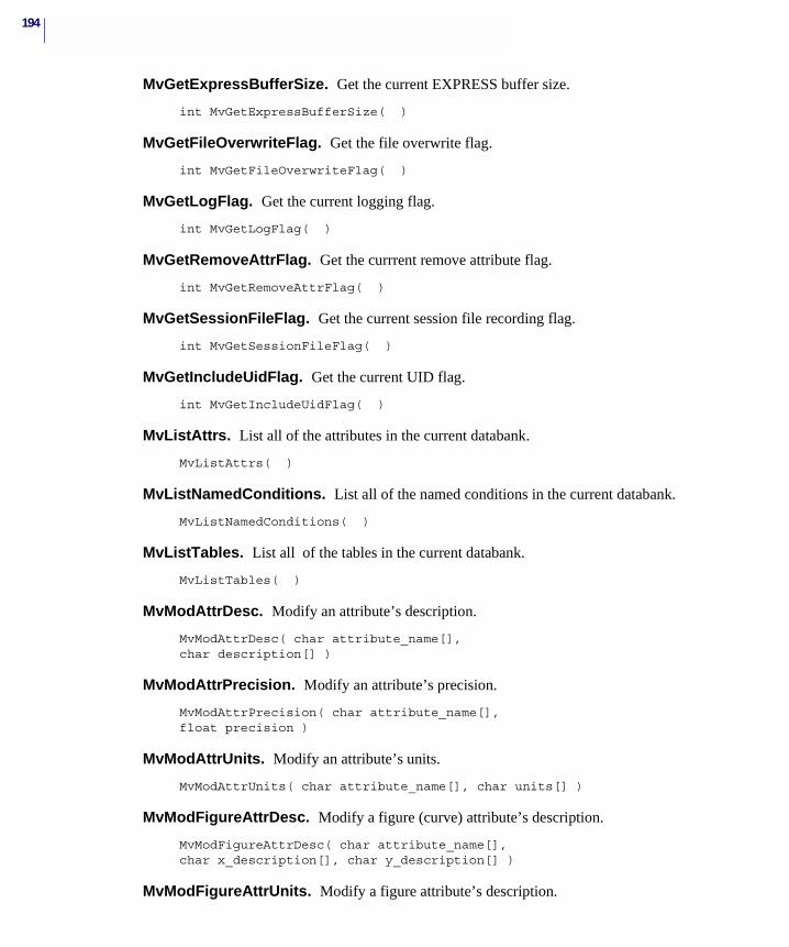
194
MvGetExpressBufferSize. Get the current EXPRESS buffer size.
int MvGetExpressBufferSize( )
MvGetFileOverwriteFlag. Get the file overwrite flag.
int MvGetFileOverwriteFlag( )
MvGetLogFlag. Get the current logging flag.
int MvGetLogFlag( )
MvGetRemoveAttrFlag. Get the currrent remove attribute flag.
int MvGetRemoveAttrFlag( )
MvGetSessionFileFlag. Get the current session file recording flag.
int MvGetSessionFileFlag( )
MvGetIncludeUidFlag. Get the current UID flag.
int MvGetIncludeUidFlag( )
MvListAttrs. List all of the attributes in the current databank.
MvListAttrs( )
MvListNamedConditions. List all of the named conditions in the current databank.
MvListNamedConditions( )
MvListTables. List all of the tables in the current databank.
MvListTables( )
MvModAttrDesc. Modify an attribute’s description.
MvModAttrDesc( char attribute_name[], char description[] )
MvModAttrPrecision. Modify an attribute’s precision.
MvModAttrPrecision( char attribute_name[], float precision )
MvModAttrUnits. Modify an attribute’s units.
MvModAttrUnits( char attribute_name[], char units[] )
MvModFigureAttrDesc. Modify a figure (curve) attribute’s description.
MvModFigureAttrDesc( char attribute_name[], char x_description[], char y_description[] )
MvModFigureAttrUnits. Modify a figure attribute’s description.
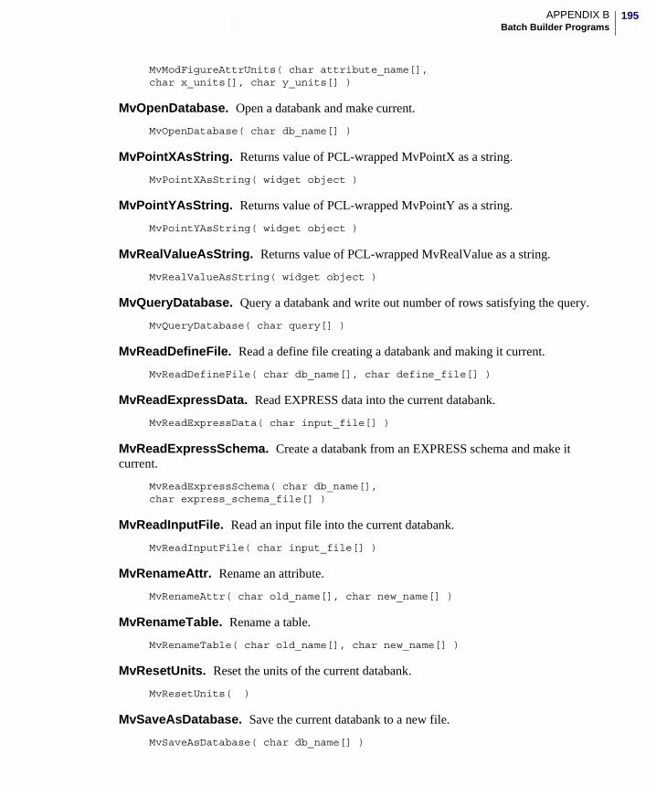
195APPENDIX BBatch Builder Programs
MvModFigureAttrUnits( char attribute_name[], char x_units[], char y_units[] )
MvOpenDatabase. Open a databank and make current.
MvOpenDatabase( char db_name[] )
MvPointXAsString. Returns value of PCL-wrapped MvPointX as a string.
MvPointXAsString( widget object )
MvPointYAsString. Returns value of PCL-wrapped MvPointY as a string.
MvPointYAsString( widget object )
MvRealValueAsString. Returns value of PCL-wrapped MvRealValue as a string.
MvRealValueAsString( widget object )
MvQueryDatabase. Query a databank and write out number of rows satisfying the query.
MvQueryDatabase( char query[] )
MvReadDefineFile. Read a define file creating a databank and making it current.
MvReadDefineFile( char db_name[], char define_file[] )
MvReadExpressData. Read EXPRESS data into the current databank.
MvReadExpressData( char input_file[] )
MvReadExpressSchema. Create a databank from an EXPRESS schema and make it current.
MvReadExpressSchema( char db_name[], char express_schema_file[] )
MvReadInputFile. Read an input file into the current databank.
MvReadInputFile( char input_file[] )
MvRenameAttr. Rename an attribute.
MvRenameAttr( char old_name[], char new_name[] )
MvRenameTable. Rename a table.
MvRenameTable( char old_name[], char new_name[] )
MvResetUnits. Reset the units of the current databank.
MvResetUnits( )
MvSaveAsDatabase. Save the current databank to a new file.
MvSaveAsDatabase( char db_name[] )
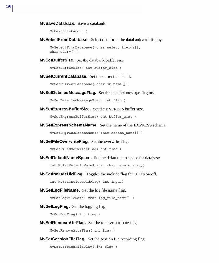
196
MvSaveDatabase. Save a databank.
MvSaveDatabase( )
MvSelectFromDatabase. Select data from the databank and display.
MvSelectFromDatabase( char select_fields[], char query[] )
MvSetBufferSize. Set the databank buffer size.
MvSetBufferSize( int buffer_size )
MvSetCurrentDatabase. Set the current databank.
MvSetCurrentDatabase( char db_name[] )
MvSetDetailedMessageFlag. Set the detailed message flag on.
MvSetDetailedMessageFlag( int flag )
MvSetExpressBufferSize. Set the EXPRESS buffer size.
MvSetExpressBufferSize( int buffer_size )
MvSetExpressSchemaName. Set the name of the EXPRESS schema.
MvSetExpressSchemaName( char schema_name[] )
MvSetFileOverwriteFlag. Set the overwrite flag.
MvSetFileOverwriteFlag( int flag )
MvSetDefaultNameSpace. Set the default namespace for database
int MvSetSefaultNameSpace( char name_space[])
MvSetIncludeUidFlag. Toggles the include flag for UID’s on/off.
int MvSetIncludeUidFlag( int input)
MvSetLogFileName. Set the log file name flag.
MvSetLogFileName( char log_file_name[] )
MvSetLogFlag. Set the logging flag.
MvSetLogFlag( int flag )
MvSetRemoveAttrFlag. Set the remove attribute flag.
MvSetRemoveAttrFlag( int flag )
MvSetSessionFileFlag. Set the session file recording flag.
MvSetSessionFileFlag( int flag )
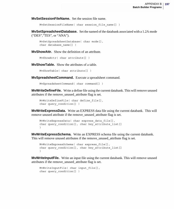
197APPENDIX BBatch Builder Programs
MvSetSessionFileName. Set the session file name.
MvSetSessionFileName( char session_file_name[] )
MvSetSpreadsheetDatabase. Set the named of the databank associated with a 1.2A mode (“DES”,”TES”, or “ANA”).
MvSetSpreadsheetDatabase( char mode[], char database_name[] )
MvShowAttr. Show the definition of an attribute.
MvShowAttr( char attribute[] )
MvShowTable. Show the attributes of a table.
MvShowTable( char attribute[] )
MvSpreadsheetCommand. Execute a spreadsheet command.
MvSpreadsheetCommand( char command[] )
MvWriteDefineFile. Write a define file using the current databank. This will remove unused attributes if the remove_unused_attribute flag is set.
MvWriteDefineFile( char define_file[], char query_condition[] )
MvWriteExpressData. Write an EXPRESS data file using the current databank. This will remove unused attribute if the remove_unused_attribute flag is set.
MvWriteExpressData( char express_data_file[], char query_condition[], char key_attribute_list[])
MvWriteExpressSchema. Write an EXPRESS schema file using the current databank. This will remove unused attributes if the remove_unused_attribute flag is set.
MvWriteExpressSchema( char express_file[], char query_condition[], char key_attribute_list[])
MvWriteInputFile. Write an input file using the current databank. This will remove unused attributes if the remove_unused_attribute flag is set.
MvWriteInputFile( char input_file[], char query_condition[] )
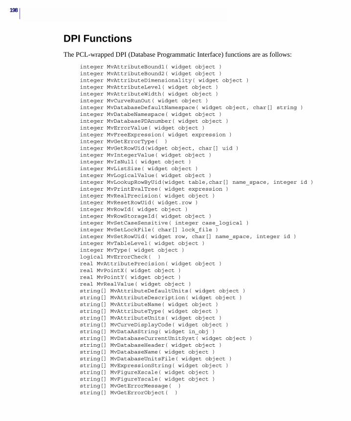
198
DPI FunctionsThe PCL-wrapped DPI (Database Programmatic Interface) functions are as follows:
integer MvAttributeBound1( widget object )integer MvAttributeBound2( widget object )integer MvAttributeDimensionality( widget object )integer MvAttributeLevel( widget object )integer MvAttributeWidth( widget object )integer MvCurveRunOut( widget object )integer MvDatabaseDefaultNamespace( widget object, char[] string )integer MvDatabeNamespace( widget object )integer MvDatabasePDAnumber( widget object )integer MvErrorValue( widget object )integer MvFreeExpression( widget expression )integer MvGetErrorType( )integer MvGetRowUid(widget object, char[] uid )integer MvIntegerValue( widget object )integer MvIsNull( widget object )integer MvListSize( widget object )integer MvLogicalValue( widget object )integer MvLookupRowByUid(widget table,char[] name_space, integer id )integer MvPrintEvalTree( widget expression )integer MvRealPrecision( widget object )integer MvResetRowUid( widget.row )integer MvRowId( widget object )integer MvRowStorageId( widget object )integer MvSetCaseSensitive( integer case_logical )integer MvSetLockFile( char[] lock_file )integer MvSetRowUid( widget row, char[] name_space, integer id )integer MvTableLevel( widget object )integer MvType( widget object )logical MvErrorCheck( )real MvAttributePrecision( widget object )real MvPointX( widget object )real MvPointY( widget object )real MvRealValue( widget object )string[] MvAttributeDefaultUnits( widget object )string[] MvAttributeDescription( widget object )string[] MvAttributeName( widget object )string[] MvAttributeType( widget object )string[] MvAttributeUnits( widget object )string[] MvCurveDisplayCode( widget object )string[] MvDataAsString( widget in_obj )string[] MvDatabaseCurrentUnitSyst( widget object )string[] MvDatabaseHeader( widget object )string[] MvDatabaseName( widget object )string[] MvDatabaseUnitsFile( widget object )string[] MvExpressionString( widget object )string[] MvFigureXscale( widget object )string[] MvFigureYscale( widget object )string[] MvGetErrorMessage( )string[] MvGetErrorObject( )
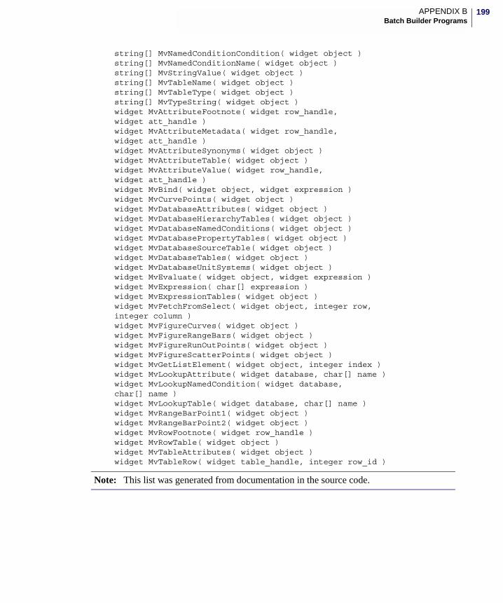
199APPENDIX BBatch Builder Programs
string[] MvNamedConditionCondition( widget object )string[] MvNamedConditionName( widget object )string[] MvStringValue( widget object )string[] MvTableName( widget object )string[] MvTableType( widget object )string[] MvTypeString( widget object )widget MvAttributeFootnote( widget row_handle, widget att_handle )widget MvAttributeMetadata( widget row_handle, widget att_handle )widget MvAttributeSynonyms( widget object )widget MvAttributeTable( widget object )widget MvAttributeValue( widget row_handle, widget att_handle )widget MvBind( widget object, widget expression )widget MvCurvePoints( widget object )widget MvDatabaseAttributes( widget object )widget MvDatabaseHierarchyTables( widget object )widget MvDatabaseNamedConditions( widget object )widget MvDatabasePropertyTables( widget object )widget MvDatabaseSourceTable( widget object )widget MvDatabaseTables( widget object )widget MvDatabaseUnitSystems( widget object )widget MvEvaluate( widget object, widget expression )widget MvExpression( char[] expression )widget MvExpressionTables( widget object )widget MvFetchFromSelect( widget object, integer row,integer column )widget MvFigureCurves( widget object )widget MvFigureRangeBars( widget object )widget MvFigureRunOutPoints( widget object )widget MvFigureScatterPoints( widget object )widget MvGetListElement( widget object, integer index )widget MvLookupAttribute( widget database, char[] name )widget MvLookupNamedCondition( widget database, char[] name )widget MvLookupTable( widget database, char[] name )widget MvRangeBarPoint1( widget object )widget MvRangeBarPoint2( widget object )widget MvRowFootnote( widget row_handle )widget MvRowTable( widget object )widget MvTableAttributes( widget object )widget MvTableRow( widget table_handle, integer row_id )
Note: This list was generated from documentation in the source code.
200
EXPRESS TranslatorsMSC.Mvision includes utilities to convert MSC.Mvision databanks to an EXPRESS formatted ASCII text files or converts the EXPRESS formatted ASCII text file to an MSC.Mvision databank. The translator uses the EXPRESS1 language to define the schema of the databank being translated and the EXPRESS physical format (data) to transfer the contents of the databank.
The EXPRESS translation utilities are useful where MSC.Mvision is being used on different computer platforms. Current MSC.Mvision databanks are not binary compatible across all platforms.2 For example, a databank built on a Digital workstation cannot be read by an HP workstation and vice versa. EXPRESS ASCII text files are platform independent and can be used on any platform to build MSC.Mvision databanks.3 The EXPRESS translator can also be used to merge data from several databanks into a single databank.
Rebuilding the MSC.Mvision databank is normally very quick because the EXPRESS model is an exact definition of the original model. When MSC.Mvision reads a standard input file, it must determine how to add the new data to the existing data. This requires time-consuming examination of the existing data. Loading the EXPRESS ASCII text file does not take as much time because it defines exactly where each piece of data belongs.
The following two EXPRESS utilities are provided:
mvision_to_express - creates an EXPRESS schema and data file from an MSC.Mvision databank.
express_to_mvision - creates an MSC.Mvision databank from an EXPRESS schema and data file.
mvision_to_expressWhen an MSC.Mvision databank is translated to EXPRESS, two files are created. The first file is the EXPRESS schema file which defines the structure of the MSC.Mvision databank in the EXPRESS language. The second file contains the data values of the databank in EXPRESS physical file format.
The command syntax is as follows.
For Unix:
mvision_to_express db_name express_name [-filter query_conditions] [-remove_unused_attributes] [-output_guid]
1EXPRESS is a language written for the PDES (Product Data Exchange using STEP) activity.2Generally, databanks built on most UNIX platforms can be read on others, but MSC.Software does not guarantee binary compatibility of databanks between different computer platforms.
3The data contained in MSC.Software-supplied databanks cannot be converted to EXPRESS without a special license.
201APPENDIX BBatch Builder Programs
[-keys key_attributes] [-b buff_size] [-overwrite] [-detailed_messages] [-log log_file]
On Windows use:
mvision_to_express.bat
• db_name - Name of the target databank.
• express_name - File name for the two EXPRESS files. The schema file will be named express_name.schema and the data file will be named express_name.data.
• -keys key_attribute - A list of databank attributes used to control the merging of the output of the file into another databank. See Merging Data on page 202.
• -filter query_condition - An optional MSC.Mvision query command to extract only specific data from the MSC.Mvision databank. For example, to get the items with a Tensile Elastic Modulus greater than 10 Msi: "E11T > 10" The string must be enclosed in double quotes.
• -remove_unused_attributes - Remove the unused empty attributes from the output.
• -b buffer_sizeSets the initial value of databank buffer size in kilobytes. The default is 10k. Increasing the size can improve performance but is limited by the available memory.
• -overwriteOverwrites existing schema and data files
• -detailed_messages - Sets the initial value of the detailed messages ON. The default is summary messages.
• -log log_file - Sets the logging flag ON and sets the name of the log file.
• -output_guid - Sets the include UID flag for UID output.
express_to_mvisionBuilding a databank from EXPRESS files takes two steps:
1. Read the EXPRESS schema file to initalize an empty MSC.Mvision databank.
2. Populate (loads) the empty databank with the contents of the EXPRESS data file or adds data to an existing databank.
Typically, you will perform both steps in a single command, but it is possible to separate the functions. If the translator is given only the schema file, it will build an empty databank and stop. Or, if the translator is given only a data file, it will look for an existing databank and merge the data file into that databank. Separating the functions is useful if there is an error in loading the data to a new databank or if you are loading data to an existing databank.
The syntax for the command is as follows.
For Unix:
express_to_mvision db_name [-s express_schema_file] [-d express_data_file]
202
[-b buff_size] [-overwrite] [-detailed_messages] [-log log_file]
On Windows use:
express_to_mvision.bat
Note: At least one of the parameters [-s express_schema_file] or [-d express_data_file] must be supplied.
Merging Data
There are times when you will want to merge the data from two similarly-defined databanks, that is databanks with a common schema. Use the key attribute feature provided in the EXPRESS translator programs.
Key attributes can be chosen by the user from the databank hierarchy when the EXPRESS data file is written, as indicated in the example below.
The express_to_mvision translator uses the key attributes to find matching entries in the target databank when the data is loaded. After a match is found, all non-key attributes in the EXPRESS data file are added to the target databank. If a match is not found, then the EXPRESS data is added with an entirely new path in the databank.
You can extract the data from one databank and merge it with another using the mvision_to_express command as shown below:
mvision_to_express demo_metals.des aluminum -filter "UNS like 'A9*'" -keys "UNS FORM TEMP"
This command creates a schema and data file (aluminum. schema and aluminum.data) from the demo_metals.des databank using only the data rows that had a UNS number that beginning with A9. The key attributes in this case are UNS, FORM, and TEMP.
To merge this data into another databank, e.g. example.des , which has the same schema as demo_metals.des, use the following command:
db_name Name for the MSC.Mvision databank being created or loaded. The system does not add a suffix to this name, so it is recommended to .des to maintain the databank naming convention.
-s express_schema_file Name of EXPRESS schema file.
-d express_data_file Name of EXPRESS data file.
-b buff_size Buffer size in kilobytes. The default is 10K.
-overwrite Overwrites existing databank file on databank creation.
-detailed_messages Sets the initial value of the detailed messages flag ON. The default is summary messages.
-log log_file Sets the logging flag ON and sets the name of the log file.
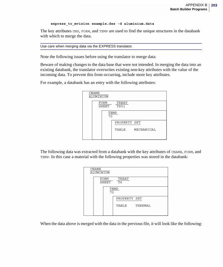
203APPENDIX BBatch Builder Programs
express_to_mvision example.des -d aluminium.data
The key attributes UNS, FORM, and TEMP are used to find the unique structures in the databank with which to merge the data.
Use care when merging data via the EXPRESS translator.
Note the following issues before using the translator to merge data:
Beware of making changes to the data base that were not intended. In merging the data into an existing databank, the translator overwrites existing non-key attributes with the value of the incoming data. To prevent this from occurring, include more key attributes.
For example, a databank has an entry with the following attributes:
The following data was extracted from a databank with the key attributes of CNAME, FORM, and TEMP. In this case a material with the following properties was stored in the databank:
When the data above is merged with the data in the previous file, it will look like the following:
CNAME
FORM
TEMP
ALUMINIUM
SHEET
70
PROPERTY SET
TABLE MECHANICAL
TREATT851
CNAME
FORM
TEMP
ALUMINIUM
SHEET
70
PROPERTY SET
TABLE THERMAL
TREATT6
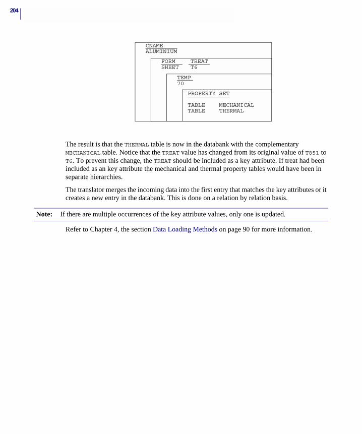
204
The result is that the THERMAL table is now in the databank with the complementary MECHANICAL table. Notice that the TREAT value has changed from its original value of T851 to T6. To prevent this change, the TREAT should be included as a key attribute. If treat had been included as an key attribute the mechanical and thermal property tables would have been in separate hierarchies.
The translator merges the incoming data into the first entry that matches the key attributes or it creates a new entry in the databank. This is done on a relation by relation basis.
Refer to Chapter 4, the section Data Loading Methods on page 90 for more information.
CNAME
FORM
TEMP
ALUMINIUM
SHEET
70
PROPERTY SET
TABLE MECHANICAL
TREATT6
TABLE THERMAL
Note: If there are multiple occurrences of the key attribute values, only one is updated.

MSC.Mvision Builder and Evaluator 2002 Installation Guide
C Shareware
� Overview
� Using Shareware
� MSC.Mvision PCL
� File Listing and Index

206
OverviewThe files provided in the Shareware directory are a collection of custom scripts, PCL functions, C source files, and support data which have been written by employees and associates of MSC.Software. They have been developed in conjunction with customers or have been used internally for Quality Assurance purposes.
Most of these programs have been well proven. This software is made available with the express understanding that it is NOT supported by MSC.Software and NO representation or guarantee is made as to its fitness for a particular task or concerning its reliability or quality.
Please use these tools at your own discretion. The utilities and scripts provided do not and are not intended to directly edit or modify databanks in any manner.
Please note that if you encounter a software defect, MSC.Software customer support may be unable to help you resolve the problem. The name of the author is generally included in some form in a readme file or script in the shareware directory. If contacting MSC.Software in regards to a problem with this shareware, the author’s name will be required.
These tools can greatly aid you in your use of the MSC.Mvision product and we recommend that you review their capabilities carefully and make use of them when you can. They have already been proven in production use and we want you to use them to your advantage.
It is requested that if you improve or correct any of the provided shareware files, that you forward the modified files to [email protected] with a brief description of the improvement or correction. If you wish to contribute to this collection of shareware please submit your files and documentation to [email protected] and it will be considered for inclusion in future releases.
207APPENDIX CShareware
Using SharewareThe Shareware directory is divided into the following sections:
• Utilities - PCL functions and scripts for databank building and verification tasks.
• Scripts - C-shell and AWK scripts that assist with MSC.Mvision file modification tasks.
• External Functions - C source code for spreadsheet external functions.
• Examples - PCL functions and scripts which can be modified to perform databank-specific tasks.
• Misc. - Specialized resource files to perform MSC.Mvision related tasks or to modify the default interface.
UtilitiesThe functions included in the shareware/utilities directory can be accessed and executed from the command line via a menu initiated with <install_dir>/shareware/bin/util,where install_dir is the full path name of the MSC.Mvision install directory. A listing of the available utilities with a brief description is provided in <install_dir>/shareware/index. A full description of each utility is provided in a README file included in each utility directory.
ScriptsThe scripts provided in the shareware/scripts directory perform many useful file editing and data verification tasks. These scripts can be executed via the <install_dir>/shareware/bin directory that contains a .wrapper script which sets up the required shell environment or can be executed directly from the command line if the proper environment is established.
External FunctionsThe C source code for the MSC.Mvision supplied spreadsheet external functions is available in the shareware/external_functions directory. These files are provided as examples for the creation of customized external functions to perform tasks which are unique to your company or application. You are free to revise these files in any manner that you deem necessary to suit you specific needs.
This source code can be compiled as detailed in Appendix B - External Functions in the MSC.Mvision Builder and Evaluator User Guide and Reference.
Note: README files are available in the individual shareware subdirectories that contain detailed descriptions and instructions for the use of the individual programs.
Note: The directory and file names in the utilities directory are used or referenced in associated scripts. Do not change the directory or file names in this directory or the associated scripts may fail.
208
The Fortran source code which was used in previous versions of the MSC.Mvision spreadsheet is available in the fortran_archive subdirectory.
ExamplesExamples of PCL functions and scripts that perform useful databank building and verification tasks which must be databank specific are provided in the shareware/examples directory. These files are provided as a guide and must be modified to address a specific databank and schema.
After creating these functions and associated scripts they can the added to the shareware/bin/util script and accessed via the utilities menu or added to the shareware bin directory.
MiscellaneousThe Misc. directory includes resource files that enable or enhance the use of external programs for use in the MSC.Mvision environment.
This directory also contains alternate resource files for modification of the default interface.

209APPENDIX CShareware
MSC.Mvision PCLMany of the utilities included in this shareware have been written using the MSC.Mvision version of the Patran Command Language (PCL). This version of PCL includes all of the Patran PCL with the exception of the Graphics (ui) functions and some system functions. The MSC.Mvision version of PCL also includes a collection of PCL wrapped DPI functions.
The Patran PCL is well documented in the Patran manuals. These manuals can be ordered online at www.mscsoftware.com or contact your local sales representative. Patran PCL is a very powerful language that can perform data manipulation routines, I/O functions, and can interact with external processes.
There is some information available for the MSC.Mvision wrapped PCL in the MSC.Mvision Builder and Evaluator User’s Guide and Reference manual. The Database Programmatic Interface (DPI) functions are documented in the MSC.Mvision Database Programmatic Interface User’s Guide and Reference.
The DPI functions and the associated PCL functions are closely related. You should review these two manuals to obtain a full understanding of the usage and capabilities of the PCL wrapper DPI functions. In addition, you should review the output in the session file for the MSC.Mvision V2006 interface, the mvbatchbuilder or the spreadsheet as an example of the syntax and usage of the PCL wrapped commands.
All of these MSC.Mvision Builder programs read instructions in PCL format and produce session files in PCL format. The output from the session files can be cut and pasted for use in PCL functions and scripts.
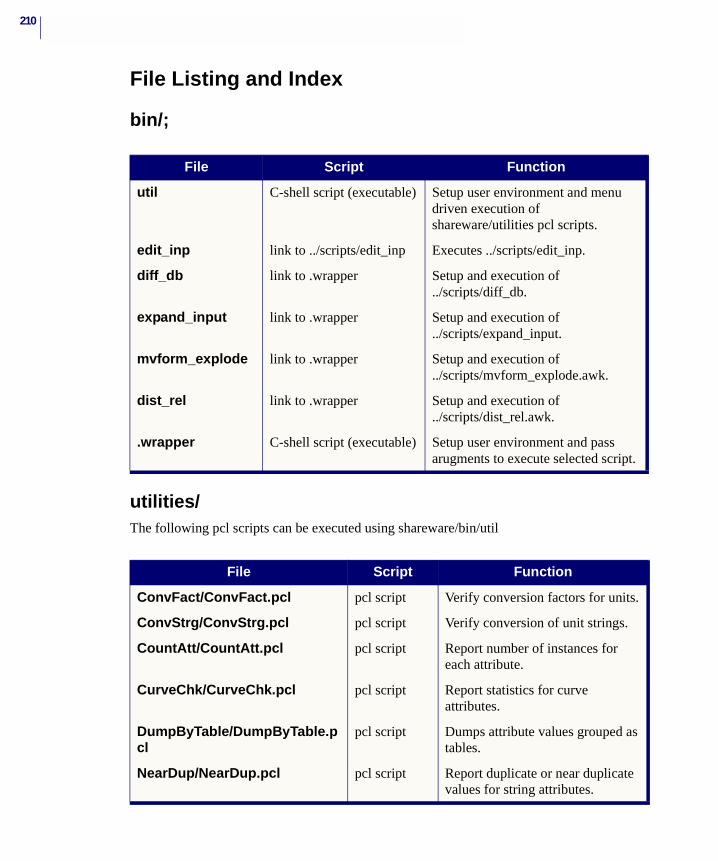
210
File Listing and Index
bin/;
utilities/The following pcl scripts can be executed using shareware/bin/util
File Script Function
util C-shell script (executable) Setup user environment and menu driven execution of shareware/utilities pcl scripts.
edit_inp link to ../scripts/edit_inp Executes ../scripts/edit_inp.
diff_db link to .wrapper Setup and execution of ../scripts/diff_db.
expand_input link to .wrapper Setup and execution of ../scripts/expand_input.
mvform_explode link to .wrapper Setup and execution of ../scripts/mvform_explode.awk.
dist_rel link to .wrapper Setup and execution of ../scripts/dist_rel.awk.
.wrapper C-shell script (executable) Setup user environment and pass arugments to execute selected script.
File Script Function
ConvFact/ConvFact.pcl pcl script Verify conversion factors for units.
ConvStrg/ConvStrg.pcl pcl script Verify conversion of unit strings.
CountAtt/CountAtt.pcl pcl script Report number of instances for each attribute.
CurveChk/CurveChk.pcl pcl script Report statistics for curve attributes.
DumpByTable/DumpByTable.pcl
pcl script Dumps attribute values grouped as tables.
NearDup/NearDup.pcl pcl script Report duplicate or near duplicate values for string attributes.
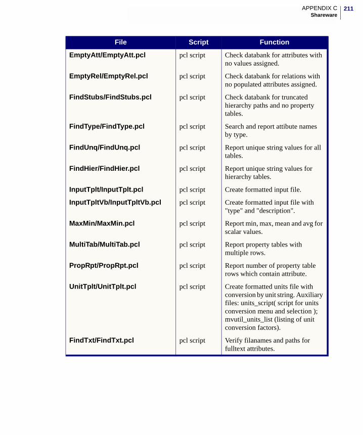
211APPENDIX CShareware
EmptyAtt/EmptyAtt.pcl pcl script Check databank for attributes with no values assigned.
EmptyRel/EmptyRel.pcl pcl script Check databank for relations with no populated attributes assigned.
FindStubs/FindStubs.pcl pcl script Check databank for truncated hierarchy paths and no property tables.
FindType/FindType.pcl pcl script Search and report attibute names by type.
FindUnq/FindUnq.pcl pcl script Report unique string values for all tables.
FindHier/FindHier.pcl pcl script Report unique string values for hierarchy tables.
InputTplt/InputTplt.pcl pcl script Create formatted input file.
InputTpltVb/InputTpltVb.pcl pcl script Create formatted input file with "type" and "description".
MaxMin/MaxMin.pcl pcl script Report min, max, mean and avg for scalar values.
MultiTab/MultiTab.pcl pcl script Report property tables with multiple rows.
PropRpt/PropRpt.pcl pcl script Report number of property table rows which contain attribute.
UnitTplt/UnitTplt.pcl pcl script Create formatted units file with conversion by unit string. Auxiliary files: units_script( script for units conversion menu and selection ); mvutil_units_list (listing of unit conversion factors).
FindTxt/FindTxt.pcl pcl script Verify filanames and paths for fulltext attributes.
File Script Function
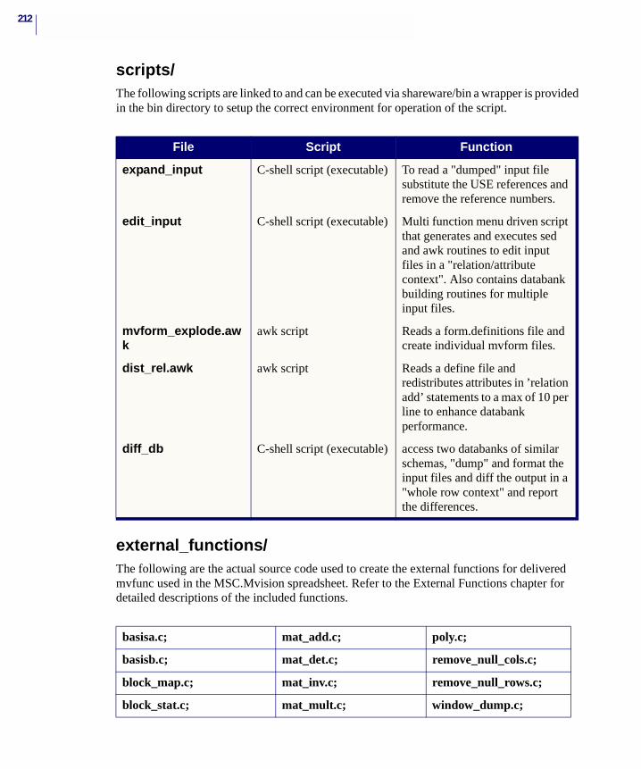
212
scripts/The following scripts are linked to and can be executed via shareware/bin a wrapper is provided in the bin directory to setup the correct environment for operation of the script.
external_functions/The following are the actual source code used to create the external functions for delivered mvfunc used in the MSC.Mvision spreadsheet. Refer to the External Functions chapter for detailed descriptions of the included functions.
File Script Function
expand_input C-shell script (executable) To read a "dumped" input file substitute the USE references and remove the reference numbers.
edit_input C-shell script (executable) Multi function menu driven script that generates and executes sed and awk routines to edit input files in a "relation/attribute context". Also contains databank building routines for multiple input files.
mvform_explode.awk
awk script Reads a form.definitions file and create individual mvform files.
dist_rel.awk awk script Reads a define file and redistributes attributes in ’relation add’ statements to a max of 10 per line to enhance databank performance.
diff_db C-shell script (executable) access two databanks of similar schemas, "dump" and format the input files and diff the output in a "whole row context" and report the differences.
basisa.c; mat_add.c; poly.c;
basisb.c; mat_det.c; remove_null_cols.c;
block_map.c; mat_inv.c; remove_null_rows.c;
block_stat.c; mat_mult.c; window_dump.c;
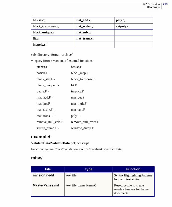
213APPENDIX CShareware
sub_directory: fortran_archive/
* legacy fortran versions of external functions
atanfit.F - basisa.F
basisb.F - block_map.F
block_stat.F - block_transpose.F
block_unique.F - fit.F
gauss.F - invpoly.F
mat_add.F - mat_det.F
mat_inv.F - mat_mult.F
mat_scale.F - mat_sub.F
mat_trans.F - poly.F
remove_null_cols.F - remove_null_rows.F
screen_dump.F - window_dump.F
example/ValidateData/ValidateData.pcl; pcl script
Function: general "data" validation tool for "databank specific" data.
misc/
block_transpose.c; mat_scale.c; extpoly.c;
block_unique.c; mat_sub.c;
fit.c; mat_trans.c;
invpoly.c;
basisa.c; mat_add.c; poly.c;
File Type Function
mvision.nedit text file Syntax Highlighting Patterns for nedit text editor.
MasterPages.mif text file(frame format) Resource file to create overlay banners for frame documents.
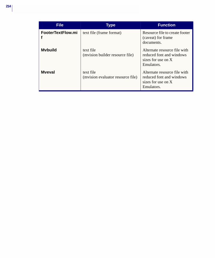
214
FooterTextFlow.mif
text file (frame format) Resource file to create footer (caveat) for frame documents.
Mvbuild text file (mvision builder resource file)
Alternate resource file with reduced font and windows sizes for use on X Emulators.
Mveval text file (mvision evaluator resource file)
Alternate resource file with reduced font and windows sizes for use on X Emulators.
File Type Function
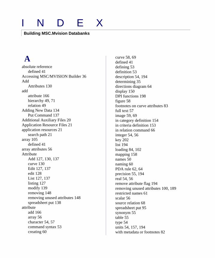
I N D E XBuilding MSC.Mvision Databanks
Aabsolute reference
defined 41Accessing MSC/MVISION Builder 36Add
Attributes 130add
attribute 166hierarchy 49, 71relation 49
Adding New Data 134Put Command 137
Additional Auxiliary Files 20Application Resource Files 21application resources 21
search path 21array 105
defined 41array attributes 56Attribute
Add 127, 130, 137curve 130Edit 127, 137edit 128List 127, 137listing 127modify 139removing 148removing unused attributes 148spreadsheet put 138
attributeadd 166array 56character 54, 57command syntax 53creating 60
curve 58, 69defined 41defining 53definition 53description 54, 194determining 35directions diagram 64display 150DPI functions 198figure 58footnotes on curve attributes 83full text 57image 59, 69in category definition 154in criteria definition 153in relation command 66integer 54, 56key 202list 194loading 84, 102mapping 158names 50naming 60PDA rule 62, 64precision 55, 194real 54, 56remove attribute flag 194removing unused attributes 100, 189restricted names 61scalar 56source relation 68spreadsheet put 95synonym 55table 55type 54units 54, 157, 194with metadata or footnotes 82
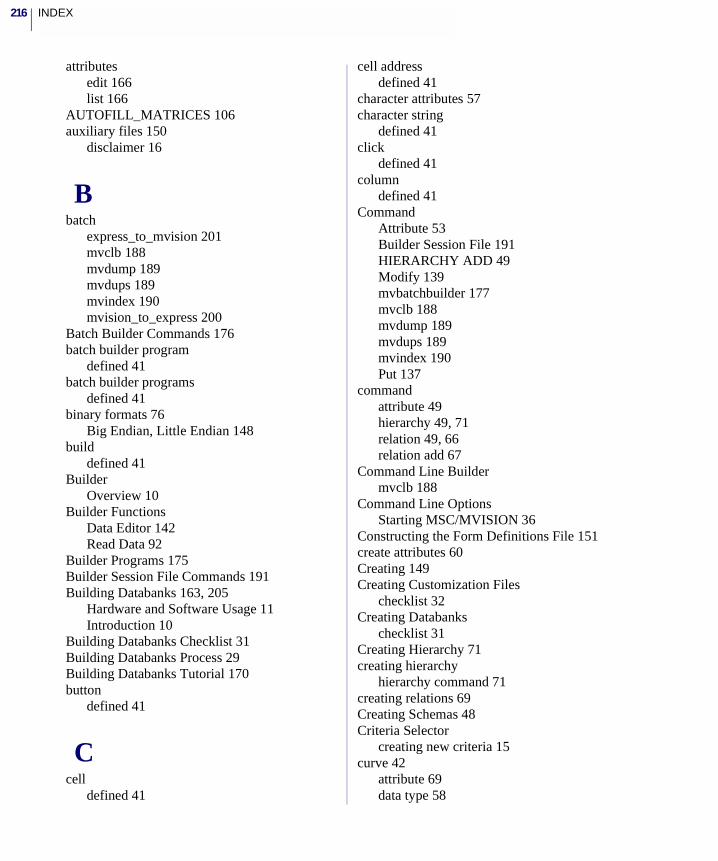
INDEX216
attributesedit 166list 166
AUTOFILL_MATRICES 106auxiliary files 150
disclaimer 16
Bbatch
express_to_mvision 201mvclb 188mvdump 189mvdups 189mvindex 190mvision_to_express 200
Batch Builder Commands 176batch builder program
defined 41batch builder programs
defined 41binary formats 76
Big Endian, Little Endian 148build
defined 41Builder
Overview 10Builder Functions
Data Editor 142Read Data 92
Builder Programs 175Builder Session File Commands 191Building Databanks 163, 205
Hardware and Software Usage 11Introduction 10
Building Databanks Checklist 31Building Databanks Process 29Building Databanks Tutorial 170button
defined 41
Ccell
defined 41
cell addressdefined 41
character attributes 57character string
defined 41click
defined 41column
defined 41Command
Attribute 53Builder Session File 191HIERARCHY ADD 49Modify 139mvbatchbuilder 177mvclb 188mvdump 189mvdups 189mvindex 190Put 137
commandattribute 49hierarchy 49, 71relation 49, 66relation add 67
Command Line Buildermvclb 188
Command Line OptionsStarting MSC/MVISION 36
Constructing the Form Definitions File 151create attributes 60Creating 149Creating Customization Files
checklist 32Creating Databanks
checklist 31Creating Hierarchy 71creating hierarchy
hierarchy command 71creating relations 69Creating Schemas 48Criteria Selector
creating new criteria 15curve 42
attribute 69data type 58
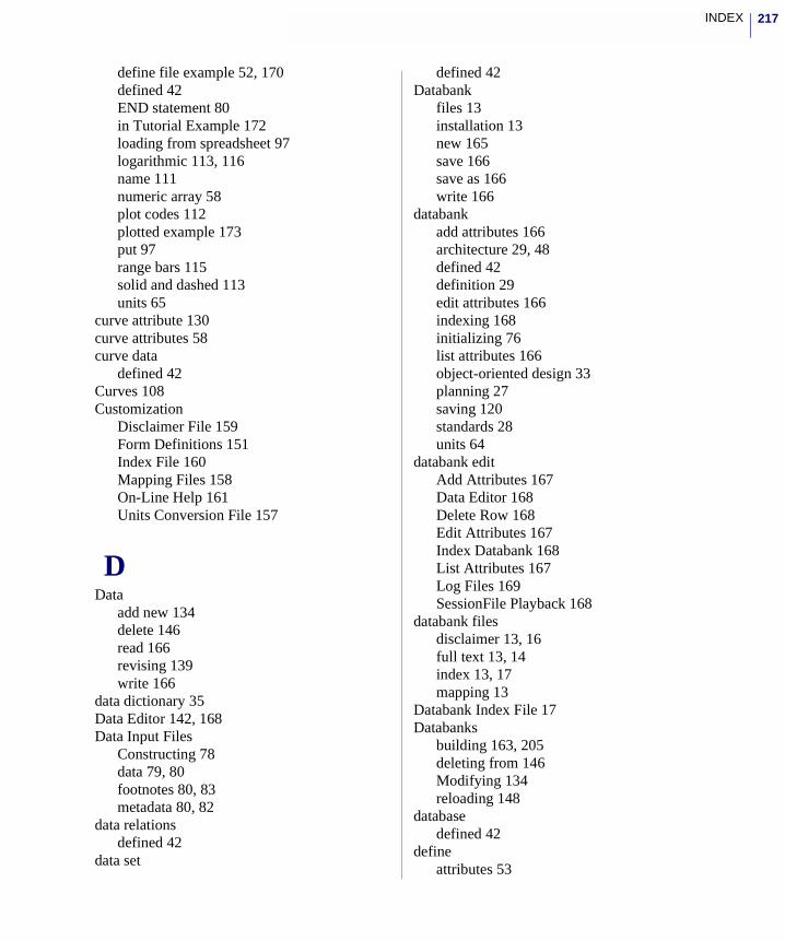
217INDEX
define file example 52, 170defined 42END statement 80in Tutorial Example 172loading from spreadsheet 97logarithmic 113, 116name 111numeric array 58plot codes 112plotted example 173put 97range bars 115solid and dashed 113units 65
curve attribute 130curve attributes 58curve data
defined 42Curves 108Customization
Disclaimer File 159Form Definitions 151Index File 160Mapping Files 158On-Line Help 161Units Conversion File 157
DData
add new 134delete 146read 166revising 139write 166
data dictionary 35Data Editor 142, 168Data Input Files
Constructing 78data 79, 80footnotes 80, 83metadata 80, 82
data relationsdefined 42
data set
defined 42Databank
files 13installation 13new 165save 166save as 166write 166
databankadd attributes 166architecture 29, 48defined 42definition 29edit attributes 166indexing 168initializing 76list attributes 166object-oriented design 33planning 27saving 120standards 28units 64
databank editAdd Attributes 167Data Editor 168Delete Row 168Edit Attributes 167Index Databank 168List Attributes 167Log Files 169SessionFile Playback 168
databank filesdisclaimer 13, 16full text 13, 14index 13, 17mapping 13
Databank Index File 17Databanks
building 163, 205deleting from 146Modifying 134reloading 148
databasedefined 42
defineattributes 53
INDEX218
define filecreating 48defined 42dumped from databank 189example 51Example Databank 51filename 99, 148formatting rules 49naming 52schema 48use with mvclb 188
Define Filesschema 48
defining hierarchy 71hierarchy command 71
defining relations 66formatting rules 66
Defining the Project 33Defining User Profile 34delete
data 147Delete Row 146, 147Deleting Data 146Designing Databanks 39
checklist 31Diagnostic Messages 100disclaimer 13, 16
default 16editing 16file 159files 16
Disclaimer File 159disclaimer file
defined 42Disclaimer Files 16Document Files 14Double precision
use of 191DPI
Database Programmatic Interface 98Database Programmatic Interface Functions
17DPI Functions 198
Eedit
attributes 166data editor 142, 168define file 170delete row 147material set 68New Databank form 172session files 97
Editing Attribute 128END data statement 80environment variable
MV_PRINT 106export
file locations 17mapping files 16, 17Remote Procedure Call 17template files 16, 17
Export Template 16export template
defined 42EXPRESS 98, 200, 201
translator 98Write Text File to Databank 99
EXPRESS Translator 200Express Translator 200EXPRESS Translators
defined 43Express translators
merge data 202express_to_mvision 201external functions 21
file location 21
FFIGURE
name of figure descriptor attribute 83, 110special Source attribute used to load images
59, 118figure
add attribute menu item 130defined 43deleting from databank 146footnote 83
219INDEX
MvFigureX/Yscale widgets 198relation 69
figure attributes 58curve attributes 58image attributes 58
figure relationsdefined 43property relations 69
fileauxiliary 150Builder log file 93, 132define file 99, 148, 170File menu of Materials Browser 92, 172form.definitionsform.definitions
file 151full text 57image 59index file 168input file 171mapping 158permission 132temporary databank file 38units conversion 64units conversion file 157
FilesApplication Resource 21databank 13Databank Index 17Disclaimer 16document 14Export Template 16Form 15Form Definitions 15Hardcopy 20Mapping Files 17MIF 20Postscript 21Session 18Startup 18Units Conversion 17XY Graphic Template 19
filesapplication resource 21graphics 20
footnotedefined 43
Form Definitions FileWildcard Forms 156
Form Definitions Files 15Form Files 15form.definitions file 13
defined 43editing 15location 15saving in a notebook 15search path 15
formatting 105Formatting Rules
define file 49formatting rules
attribute 53defining relations 66heirarchy command 71
FormsNew Databank Form 78
full text attribute 57defined 43Helper 58
full text documents 13, 14editing 14location of 14
HHardcopy Files 20help 29
defined 43Helper 58Hierarchy
add 71creating 71modifying 125
hierarchy 67add 49define 71defined 43
hierarchy commandformatting rules 71
hierarchy relationsdefining relations 67
INDEX220
Iimage
attribute 59, 69data type 58defined 43file 59formats 117sample entry in load file 118
image relationsdefined 43
Import, select, or analyze materials 12Index File 160index file 13, 17
defined 43indexing databank
mvindex 190input file
defined 43Interactive Builder 91
Kkey
attribute 202keywords
restricted terms 61
Llicenses
MSC/MVISION 36list
attributes 166load
defined 44load file
metadata 82Loading Data 102
Curves 108Figures
curve 108Images 117Log and Semilog Curves 116Plot Codes 116
Range Bars 115Scatter Points and Runout Points 114Solid and Dashed Curves 113Tangent Runout Point 115
Saving Databanks 120Tables
Full Text Data 107Loading Data Methods
Command Line Builder 91, 94Database Programmatic Interface 91, 98Diagnostic Messages 100EXPRESS Utilities 91, 98Interactive Builder 90, 91Session Files 91, 97Spreadsheet 91, 94
Loading Tables 102
Mmapping
file 158Mapping Files 17mapping files 13
defined 44material
defined 44material properties
defined 44material sets
creating 15Materials Browser
creating new material sets 15Materials Browser window
defined 44matrix
array attribute 56formatting 106
matrix attribute 192Matrix Browser 12menu bar
defined 44menu option
defined 44menu title
defined 44
221INDEX
Merge KeyExamples 89
Merge Keys 88#i 88ADD 88Examples 89EXI 88USE 88
merge keysdefined 44
Merging Data 202metadata 82
defined 44MIF Files 20Modify
Command 139Databanks 134
Modify Commandformat 139
ModifyingDatabanks 166
Modifying Hierarchy 125Motif window
defined 44mouse button
defined 45MSC.Mvision Databanks 22MSC.Mvision PCL Commands 191MSC/MVISION Builder
session files 18MSC/MVISION Databank
defined 45MSC/MVISION Databank Files 13MSC/MVISION Databanks 12MV_PRINT 106mvclb 188mvdump 189mvdups 189mvindex 190mvision_to_express 200
Nnaming attributes 60
recommended naming conventions 61
restricted keywords 61naming define files 52New Databank 165notebook 16null
symbol 50
OObject-Oriented Design 33On-Line Help 161on-line help
defined 45online help 29on-line manual
defined 45Organizing the Project 33
Getting Started 33
Ppane
defined 45path
defined 45PDA rule
attribute 62, 64pedigree
defined 45Pedigree Window 14Planning Databanks
checklist 31Planning the Project 35plot codes
curve 112popup menu
defined 45Postscript Files 21Precision
defining 55double 191
precisionsingle 191
Preliminary InformationPlanning Databanks 28
INDEX222
Print or export to analysis 12printing
postscript files 21selecting printer 21
Product Data Management (PDM) 30properties
defined 45Property Relations
Defining Relations 68property relations
figure 68table 68table relations 69
property tablesdefined 45
Prototypescreating 89
pulldown menudefined 46
Put 137
Rradio button
defined 46Read Data 166realtion
figure 68relation
add 49, 66creating 69creating attributes 69defined 46defining 66determining 35figure 69footnotes on figure relations 83hierarchy 67names 50source 67table 68types 67
relation command 66relation name
defined 46
relation type 67figure 67hierarchy 67property 67source 67
relative referencedefined 46
Reloading Databanks 148Remote Procedure Cabute expressions 17resource settings 21Reviewing
Listing Schema Relations and Attributes 125Schemas 125
Reviewing Schemas 125Revising
Data 139Data Editor 142Overview Schemas and Databanks 124Reviewing Schemas 125Schemas 127
Revising Schemas and Databankschecklist 32
rowdefined 46
SSave Databank 166Save Databank As 166saving
notebooks 16settings 19
scalardefined 46
scalar attributes 56schema 48
attribute 48attributes 29building databanks with spreadsheet 95components 29, 48create 48databank design 30define file 48defined 46design considerations 48
223INDEX
example 170EXPRESS 200formatting rules 49hierarchy 29, 48relations 29, 48removing unused attributes 100reviewing and modifying 166units 64writing databank 99
SchemasReviewing 125Revising 127
scrolldefined 46
Search by lists or properties 12select
defined 46session file playback
defined 46Session Files 18session files 18
builder 18spreadsheet 18
Set Default Namespace 145settings
files 19saving 19
single binary format 148Software
Usage 11Software Usage 11source
defined 46source relation
defined 47source relations
defining relations 67spreadsheet
defined 47session files 18, 19
standardsdatabank 28
start up files 18graphics templates 18, 20notebooks 18settings 18
spreadsheet 18, 19starting
MSC/MVISION 36Startup Files 18string
defined 47
Ttable attributes 55tables
deleting from databank 146tear-off menu
defined 47templates
export 16graphics 20mapping 16
Terminology 41Terms 41toggle
defined 47tools
defined 47Translate Data
EXPRESS 200express_to_mvision 201mvision_to_express 200
UUnderstanding Terms 41units
attribute definition 54conversion file 157curve 65databank 64schema 64units conversion file 157
units conversionfile 64
Units Conversion File 157units conversion file
defined 47Units Conversion Files 17
INDEX224
Using Disk Space Management 38
VView and Compare Data 12
WWildcard Forms 156Window
pedigree 14windows
defined 47Windows file 19Write
Databank 148to Log File 132
writeto database 95
Write Data 166Write Databank 166Write Databank… 166
XXY Graphics
templates 20XY Graphics
template files 20