multivariate analysis of variables affecting thermal ... · multivariate analysis of variables...
TRANSCRIPT

1
Multivariate Analysis of Variables Multivariate Analysis of Variables Affecting Thermal Performance Affecting Thermal Performance
of Black Liquor Evaporatorsof Black Liquor Evaporators
Hamideh Hajiha & Honghi Tran (University of Toronto)Odessa Websdale, Denys Holik & Bill Downing (DMI)
2
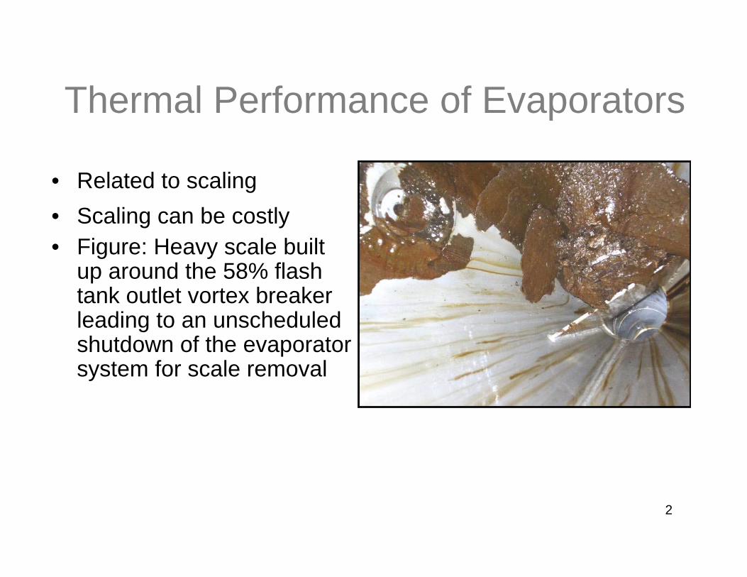
Thermal Performance of Evaporators
• Related to scaling • Scaling can be costly• Figure: Heavy scale built
up around the 58% flash tank outlet vortex breaker leading to an unscheduled shutdown of the evaporator system for scale removal

3
Kraft Recovery Process
Wood
Pulp
RecoveryBoiler
GreenLiquor
WhiteLiquor WashingWashingLime
MudLime
Lime Kiln
CausticizingPlant
Water
RecoveryBoiler
HeavyHeavyBlack LiquorBlack Liquor70% solids70% solids
GreenLiquor
WhiteLiquor WashingWashingWashingWashing
WeakWeakBlack LiquorBlack Liquor15% solids15% solids
LimeMud
Lime
Smelt
Lime KilnLime Kiln
CausticizingPlant
CausticizingPlant
Water
Evaporators
PulpingDigester

4
Potential Factors Affecting Thermal Performance of Evaporators
• Equipment
• Operation
• Black liquor property

5
Objective
• To determine correlations between thermal performance and operating conditions of black liquor evaporators using multivariate data analysis techniques

6
Approach
• Mill visit and data collection
• Multivariate data analysis:
Study many interconnected parameters simultaneously
Study correlations that may exist among parameters

7
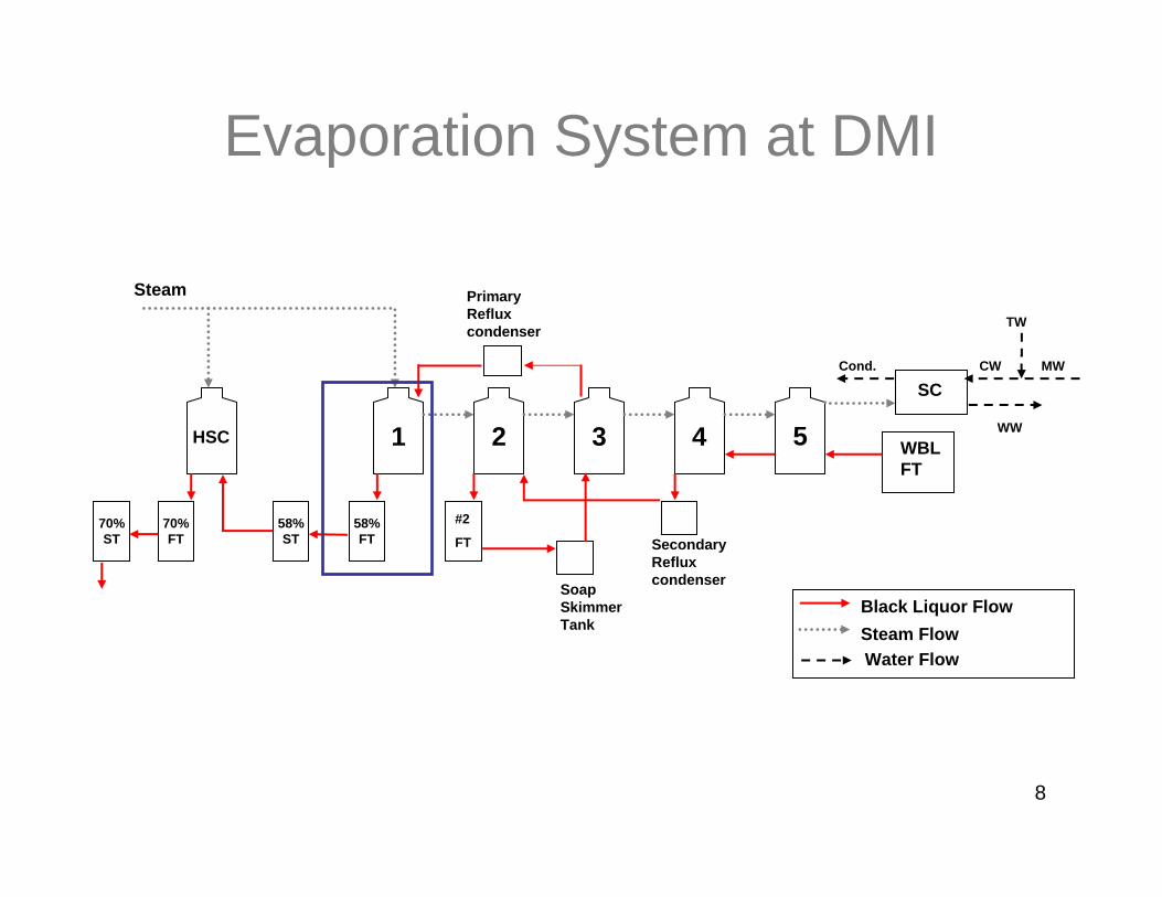
Evaporators at DMI
5 effect Falling Film Evaporators
467 ton/hr WBL at 13.5% solids and 85 °C
109 ton/hr SBL at 58% solids and 115°C
8
Evaporation System at DMI
Black Liquor FlowSteam Flow
4 5321
#2
FT58% FT Secondary
Reflux condenser
WBL FT
Soap Skimmer Tank
58% ST
70% FT
70% ST
Steam
SC
HSC WW
MW
TW
CWCond.
Primary Reflux condenser
Water Flow

9
Scaling at DMI
10
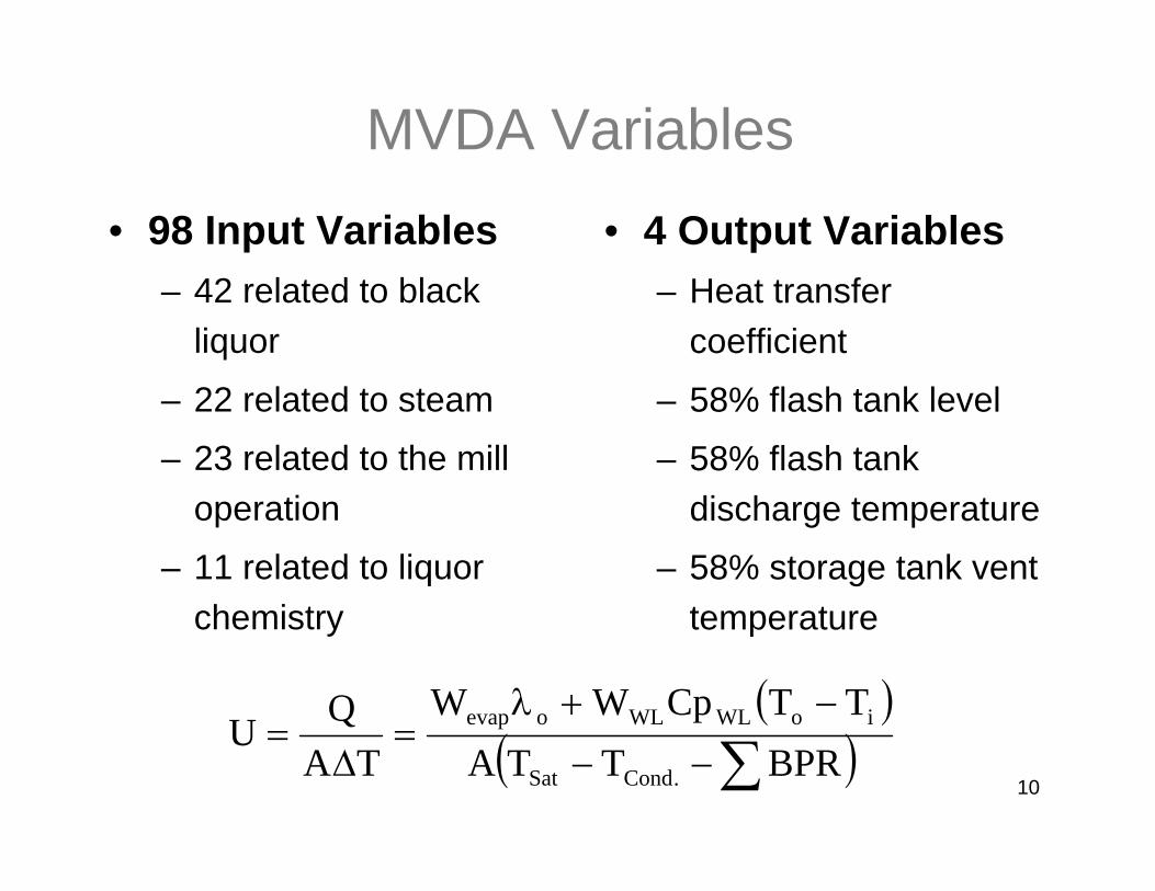
• 98 Input Variables– 42 related to black
liquor
– 22 related to steam
– 23 related to the mill operation
– 11 related to liquor chemistry
• 4 Output Variables– Heat transfer
coefficient
– 58% flash tank level
– 58% flash tank discharge temperature
– 58% storage tank vent temperature
( )( )∑−−
−+λ=
Δ=
BPRTTATTCpWW
TAQU
.CondSat
ioWLWLoevap
MVDA Variables

11
• The first Principal Component (PC) models the direction of largest variation in the data
TTA
Steam Flowrate
BL Solids
PC #1
MVDA Techniques (PCA)

12
PC #1
PC #2
TTA
BL Solids
Steam Flowrate
MVDA Techniques

13
Day 3
Day 2
Day 1
BL Solids
TTASteam Flowrate
Day 3
Day 2
Day 1
58% FT Level
58% FT Discharge
Temp
Heat Transfer
Coeff.
Inputs Outputs
Partial Least Squares Regression (PLS)

14
Scatter Plot
-8
-6
-4
-2
0
2
4
6
8
-14 -13 -12 -11 -10 -9 -8 -7 -6 -5 -4 -3 -2 -1 0 1 2 3 4 5 6 7 8 9 10 11 12
t[2]
t[1]
1
2
3
4
5
6
7
8
9101112
1314
15
16
1718
192021
2223 2425
26
2728 29
30 31
3233
34
35
3637
38
39
40
41
42
43
45
4950
52
5455
56
575859
60
61
626364
65
66
6768
69
7071
72
7374
7576
77
78
79
80
81
82
83
848586
87
88
89
90
91
92
93 94 95
96
97 98
99
100
102 103104105
106
107
108
109110
111
112
113114
116
117118119
120
121
122123 125126127128
129 130
131 132133
134135
136
137
138
139
140141
142
143144145
146
147
161162
163
164165167
168
169
171
172
173174
175
176177
178179 180
181
182
183
184185186187
188
189190
191
193194195
196197198
199
200
201
202
203204
205
206207
208209210
211
212
213214215
216
217
218 219220221 222
223
224225
226
227
229
230231 232
233234
235236237
238
239
240
241242243244
245246
247248
249250 251
252
253
254255256
257
258
259
260
261
262
263
264
265
266
267268
269270
271 272 273
274
275276
277278279280
281
282
283
284
286 287
288
289
290
291
292
293294295
296297298
299
300
301302303
304305306
307
308309
312
313314
315316317
318
319
320
321322
323
324325
326
327
328329330
331
332333
334
335336
337
338 339
340
341
342
343344
345346347348349
350351
352
353354
355
356
357
358
359360
361362 363
364365
II
III
I
IV
95% Confidence Interval
-8
-6
-4
-2
0
2
4
6
8
-12 -11 -10 -9 -8 -7 -6 -5 -4 -3 -2 -1 0 1 2 3 4 5 6 7 8 9 10 11 12
t[2]
t[1]
11
53 24
6
1/01/07
2/01/07
3/01/07

15
Loading plot
Steam flow to 1st effect
HSC boiling point rise
Steam pressure to evaps
70% Storage tank level
3rd effect recirc. pump load
70% FT vapor pressure
Wash residual EA
Clean condensate conductivity
Steam pressure to HSC heaters
I
IV
II
III
WBL flow to FT

16
Scatter and Loading Plot
• Quad II - Higher:– Steam P, T, flow to
HSC
– HSC boiling point rise
– Product BL % solids
• Quad III - Higher:– Steam P, T, flow to
evaporators
– WBL flow to flash tank
– Evaporation across effects

17
Coefficient Plot H
eat T
rans
fer C
oeff.
0
5
-5
-10
WB
L Fl
ow to
WB
L Fl
ash
Tank
WB
L %
Sol
ids
to W
BL
Flas
h Ta
nk
4th
Effe
ct R
ecirc
. Pum
p Lo
ad
Ste
am F
low
to 1
st E
ffect
Ste
am T
emp
to 1
st E
ffect
Ste
am P
ress
ure
to E
vapo
rato
rs
Man
ual V
alve
Ste
am to
1st
Effe
ct
1st E
ffect
Boi
ling
Poi
nt R
ise
Eva
pora
tion
acro
ss E
ffect
s
Coo
ling
Wat
er F
low
to S
C
Tem
perin
g W
ater
Flo
w to
SC
Mill
Wat
er T
emp
to S
C
War
m W
ater
Tem
p fro
m S
C
2nd
Effe
ct T
rans
fer P
ump
Load
70%
BL
Stor
age
Tank
#2
Leve
l

18
Heat Transfer Coefficient
COOLING WATER FLOW TO SC
WBL FLOW TO FLASH TANK
TOTAL WATER EVAPORATED
ACROSS EFFECTS
STEAM PRESSURE TO EVAPS
WBL % SOLIDS TO FLASH TANK
-4
-2
0
2
4
6

19
58% Flash Tank Level
STEAM PRESSURE TO
EVAPS
WASH RESIDUAL EA
TEMPERING WATER FLOW TO
SC
MILL WATER TEMP TO SC
-4
-2
0
2
4

20
58% Flash Tank Discharge Temp
#2 EFFECT TRANSFER PUMP
LOAD
TEMPERING WATER FLOW TO
SC
#4 EFFECT RECIRC. PUMP
LOAD
-2
0
2
4

21
58% Storage Tank Vent Temp
WBL FLOW TO FLASH TANK
TEMPERING WATER FLOW
TO SC
COOLING WATER FLOW TO SC
-4
-2
0
2
4

22
-1.43.7WBL Flow to F.T.
-1.1-3.0Steam Pressure to Evaporators
2.52.3Cooling Water Flow to SC
-3.3WBL % Solids to F.T.
-3.4-1.7-2.2Tempering Water Flow to SC
58% STVentTemp
58% FTDis.
Temp
58% FTLevelUVariables
SC=Surface Condenser, FT=Flash Tank, ST=Storage Tank, Dis.=Discharge

23
400
500
600
700
800
1/1/07 1/4/07 30/6/07 28/9/07 27/12/07
Date
U (K
J/m
2 hr-C
)Overall Heat Transfer Coefficient

24
Chi
pmet
erS
peed
WBL
Sto
rage
Tan
k #1
WBL
Sto
rage
Tan
k #2
WBL
Flo
w to
Fla
sh T
ank
WBL
% S
olid
s to
Fla
sh T
ank
BL
Mas
s Fl
ow to
Eva
pora
tors
WBL
Tem
pera
ture
to 5
th E
ffect
5th
Effe
ct R
ecirc
. Tem
pera
ture
4th
Effe
ct R
ecirc
. Tem
pera
ture
2nd
Effe
ct R
ecirc
. Tem
pera
ture
3rd
Effe
ct R
ecirc
. Tem
pera
ture
1st E
ffect
Rec
irc. T
empe
ratu
re5t
h E
ffect
Lev
el2n
d E
ffect
Lev
el5t
h E
ffect
Rec
irc. P
ump
Load
4th
Effe
ct R
ecirc
. Pum
p Lo
ad2n
d E
ffect
Rec
irc. P
ump
Load
3rd
Effe
ct R
ecirc
. Pum
p Lo
ad1s
t Effe
ct R
ecirc
. Pum
p Lo
adS
team
Flo
w to
1st
Effe
ctS
team
Tem
pera
ture
to 1
st E
ffect
Ste
am P
ress
ure
to E
vapo
rato
rsM
anua
l Val
ve S
team
to 1
st E
ffect
1st E
ffect
Vap
our P
ress
ure
2nd
Effe
ct V
apou
r Pre
ssur
e3r
d E
ffect
Vap
our P
ress
ure
4th
Effe
ct V
apou
r Pre
ssur
e5t
h E
ffect
Vap
our P
ress
ure
Sur
face
Con
dens
er P
ress
ure
1st E
ffect
Boi
ling
Poin
t Ris
eE
vapo
ratio
n ac
ross
Effe
cts
Coo
ling
Wat
er F
low
to S
CTe
mpe
ring
Wat
er F
low
to S
CM
ill W
ater
Tem
pera
ture
to S
CW
arm
Wat
er T
emp.
from
SC
Cle
an C
onde
nsat
e C
ondu
ctiv
ity
Com
bine
d C
onde
nsat
e C
ondu
ctiv
ityFo
ul c
onde
nsat
e C
ondu
ctiv
ity2n
d E
ffect
Fla
sh T
ank
Leve
lSB
L Te
mp.
-Soa
p Sk
imm
er T
ank
2nd
Effe
ct T
rans
fer P
ump
Load
Soa
p S
kim
mer
Tan
k Le
vel
58%
BL
Sto
rage
Tan
k Le
vel
BL
Flow
to H
SCSB
L %
Sol
ids
BL T
emp.
to N
. HSC
Hea
ter
BL
Tem
p. to
S. H
SC H
eate
rB
L Te
mp.
from
N. H
SC
Hea
ter
BL
Tem
p. fr
om S
. HS
C H
eate
rH
SC
Pre
ssur
eH
SC
Boi
ling
Poi
nt R
ise
Ste
am F
low
to H
SC H
eate
rsS
team
Tem
p. to
HSC
Hea
ters
Ste
am P
ress
ure
to H
SC
De-
SHC
ontro
l Val
ve S
team
to H
SC H
eate
rsM
anua
l Val
ve S
team
to H
SC H
eate
rsN
. HS
C S
team
Mas
s Fl
owS
. HS
C S
team
Mas
s Fl
owE
vapo
ratio
n ac
ross
HSC
70%
BL
Sto
rage
Tan
k Te
mpe
ratu
re70
% F
lash
Tan
k V
apou
r Pre
ssur
eP
rodu
ct B
L %
Sol
ids
70%
BL
Sto
rage
Tan
k #1
Lev
el70
% B
L S
tora
ge T
ank
#2 L
evel
1100
KPa
Ste
am F
low
to E
ject
ors
400
KPa
Ste
am F
low
to S
tripp
erC
onde
nsat
e S
tripp
er T
empe
ratu
reS
tripp
ed C
onde
nsat
e to
Rec
aust
Mill
Wat
er to
Trim
Con
dens
er T
emp
% C
aust
icity
EA-to
-Woo
dS
peci
es in
to C
hipm
eter
MC
C E
AW
ash
Res
idua
l EA
KAPP
A #
0
0
Hig
h U
Per
iod
Low
U P
erio
d
12
-1-2
-1-2
21
Comparison of Contribution Plots
Vapor pressure in effects

25
• Higher U periods had:– a lower WBL % solids to FT, and recirculation pump
load
– a higher steam temperature, pressure and flow rate to the 1st effect
– a higher WBL Temp, and flow rate
– a higher cooling water flow rate to SC
– a higher vapour pressure in effects
High vs. Low U Periods:

26
Conclusion
• The water flow rate to the surface condenser, the weak black liquor % solids, and the weak black liquor flow rate to the evaporators were found to be the dominant parameters in the PLS model of the evaporators based on the loading plot and VIP plot

27
• Abitibi-Bowater• Alstom Power• Andritz• Aracruz Celulose• Babcock & Wilcox• Boise Paper Solutions• Carter Holt Harvey• Cenibra• Clyde-Bergemann• DMI Peace River Pulp
• Diamond Power International• Domtar• Georgia Pacific• International Paper• Irving Pulp & Paper• Metso Power• MeadWestvaco• Stora-Enso Research• Tembec• Votorantim Celulose E Papel• NSERC
AcknowledgementsMembers of Increasing Energy and Chemical
Recovery Efficiency in the Kraft Process

28
Thank YouThank You
29
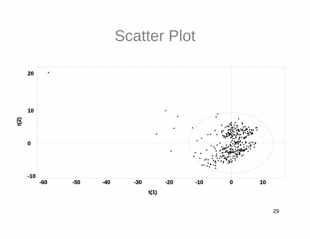
Scatter Plot
-60 -50 -40 -30 -20 -10 0 10
t(1)
20
10
0
-10
t(2)
-60 -50 -40 -30 -20 -10 0 10
t(1)
20
10
0
-10
t(2)

30
Contribution Plot for the Outlier
-20
-10
0
10
20
N R W C E L E E E E E C U T
Prod
uctio
n R
ate
Chi
pmet
erSp
eed
WBL
Sto
rage
Tan
k #1
WBL
Sto
rage
Tan
k #2
WBL
Flo
w to
Fla
sh T
ank
WBL
% S
olid
s to
Fla
sh T
ank
Mas
s Fl
ow B
L So
lids
to E
vapo
rato
rsW
BL T
empe
ratu
re to
5th
Effe
ct5t
h E
ffect
Rec
ircul
atio
n Te
mpe
ratu
re4t
h E
ffect
Rec
ircul
atio
n Te
mpe
ratu
re2n
d Ef
fect
Rec
ircul
atio
n Te
mpe
ratu
re3r
d Ef
fect
Rec
ircul
atio
n Te
mpe
ratu
re1s
t Effe
ct R
ecirc
ulat
ion
Tem
pera
ture
5th
Effe
ct L
evel
4th
Effe
ct L
evel
2nd
Effe
ct L
evel
3rd
Effe
ct L
evel
1st E
ffect
Lev
el5t
h Ef
fect
Rec
ircul
atio
n Pu
mp
Load
4th
Effe
ct R
ecirc
ulat
ion
Pum
p Lo
ad2n
d E
ffect
Rec
ircul
atio
n Pu
mp
Load
3rd
Effe
ct R
ecirc
ulat
ion
Pum
p Lo
ad1s
t Effe
ct R
ecirc
ulat
ion
Pum
p Lo
adSt
eam
Flo
w to
1st
Effe
ctSt
eam
Tem
pera
ture
to 1
st E
ffect
Stea
m P
ress
ure
to E
vapo
rato
rsC
ontro
l Val
ve S
team
to 1
st E
ffect
Man
ual V
alve
Ste
am to
1st
Effe
ct1s
t Effe
ct V
apou
rPre
ssur
e2n
d Ef
fect
Vap
ourP
ress
ure
3rd
Effe
ct V
apou
rPre
ssur
e4t
h Ef
fect
Vap
ourP
ress
ure
5th
Effe
ct V
apou
rPre
ssur
eSu
rface
Con
dens
er P
ress
ure
1st E
ffect
Boi
ling
Poi
nt R
ise
Eva
pora
tion
Acro
ss E
ffect
sSt
eam
Eco
nom
y Ac
ross
Effe
cts
Coo
ling
Wat
er F
low
to S
CTe
mpe
ring
Wat
er F
low
to S
CM
ill W
ater
Tem
pera
ture
to S
CW
arm
Wat
er T
empe
ratu
re fr
om S
CC
lean
Con
dens
ate
Con
duct
ivity
C
ombi
ned
Con
dens
ate
Con
duct
ivity
Foul
con
dens
ate
Con
duct
ivity
2nd
Effe
ct F
lash
Tan
k Le
vel
SBL
Tem
p. S
oap
Skim
mer
Tan
k2n
d Ef
fect
Tra
nsfe
r Pum
p Lo
adSo
ap S
kim
mer
Tan
k Le
vel
Skim
med
Liq
uor P
ump
Load
58%
BL
Stor
age
Tank
Lev
el58
% F
lash
Tan
k Le
vel
58%
Fla
sh T
ank
Dis
char
ge T
empe
ratu
reBL
Flo
w to
HS
CSa
ltcak
eAd
ditio
nSB
L %
Sol
ids
BL T
empe
ratu
re In
to N
. HSC
Hea
ter
BL T
empe
ratu
re In
to S
. HSC
Hea
ter
BL T
empe
ratu
re O
ut o
f N. H
SC H
eate
rBL
Tem
pera
ture
Out
of S
. HSC
Hea
ter
HSC
Pre
ssur
eH
SC B
oilin
g P
oint
Ris
eSt
eam
Flo
w to
HS
C H
eate
rsSt
eam
Tem
pera
ture
to H
SC
Hea
ters
Stea
m P
ress
ure
to H
SC D
esup
erhe
ater
Con
trol V
alve
Ste
am to
HSC
Hea
ters
Man
ual V
alve
Ste
am to
HS
C H
eate
rsE
vapo
ratio
n N
. HS
C S
tem
Mas
s Fl
owEv
apor
atio
n S.
HSC
Ste
m M
ass
Flow
Evap
orat
ion
Acro
ss H
SC
Stea
m E
cono
my
Acro
ss E
ffect
s &
HS
C70
% B
L S
tora
ge T
ank
Tem
pera
ture
70%
Fla
sh T
ank
Vapo
urPr
essu
re70
% F
lash
Tan
k Le
vel
Prod
uct B
L %
Sol
ids
70%
BL
Stor
age
Tank
#1
Leve
l70
% B
L St
orag
e Ta
nk #
2 Le
vel
1100
KPa
Stea
m F
low
to E
ject
ors
400
KPa
Stea
m F
low
to S
tripp
erFo
ul C
onde
nsat
e Fl
ow to
Stri
pper
Pre
heat
erFo
ul C
onde
nsat
e Te
mp.
to S
tripp
er P
rehe
ater
Con
dens
ate
Strip
per L
evel
Con
dens
ate
Tem
p. S
tripp
er U
pper
Sec
tion
Con
dens
ate
Tem
p. S
tripp
er L
ower
Sec
tion
Strip
ped
Con
dens
ate
to R
ecau
stM
ill W
ater
to T
rim C
onde
nser
Tem
pW
arm
Wat
er T
empe
ratu
re to
Trim
Con
dens
erN
CG
Pre
ssur
e fro
m T
rim C
onde
nser
%C
asut
icity
Gre
en L
iquo
r Red
uctio
nTo
tal T
itrat
able
Alka
liC
aust
ic F
low
to W
hite
Liq
uor S
tora
ge T
ank
EA-to
-Woo
dSp
ecie
s in
to C
hipm
eter
Extra
ctio
n R
esid
ual f
rom
Dig
este
r M
CC
EA
Was
h R
esid
ual E
A58
% B
L St
orag
e Ta
nk V
ent T
empe
ratu
reKA
PPA
#(T
o-Ti
)liqu
or1s
t Effe
ct R
ecirc
ulat
ion
Tem
p. in
kel
vin
Late
nt H
eat o
f Wat
er O
utC
Pw
lQ
-Tot
al H
eat T
rans
ferr
ed in
Eva
psde
lta T
U-O
vera
ll H
eat T
rans
fer C
oeffi
cien
tW
evap
/Chi
pmet
erSp
eed
U/C
hipm
eter
Spee
d
Prod
uctio
n R
ate
Chi
pmet
erSp
eed
WBL
Sto
rage
Tan
k #1
WBL
Sto
rage
Tan
k #2
WBL
Flo
w to
Fla
sh T
ank
WBL
% S
olid
s to
Fla
sh T
ank
Mas
s Fl
ow B
L So
lids
to E
vapo
rato
rsW
BL T
empe
ratu
re to
5th
Effe
ct5t
h E
ffect
Rec
ircul
atio
n Te
mpe
ratu
re4t
h E
ffect
Rec
ircul
atio
n Te
mpe
ratu
re2n
d Ef
fect
Rec
ircul
atio
n Te
mpe
ratu
re3r
d Ef
fect
Rec
ircul
atio
n Te
mpe
ratu
re1s
t Effe
ct R
ecirc
ulat
ion
Tem
pera
ture
5th
Effe
ct L
evel
4th
Effe
ct L
evel
2nd
Effe
ct L
evel
3rd
Effe
ct L
evel
1st E
ffect
Lev
el5t
h Ef
fect
Rec
ircul
atio
n Pu
mp
Load
4th
Effe
ct R
ecirc
ulat
ion
Pum
p Lo
ad2n
d E
ffect
Rec
ircul
atio
n Pu
mp
Load
3rd
Effe
ct R
ecirc
ulat
ion
Pum
p Lo
ad1s
t Effe
ct R
ecirc
ulat
ion
Pum
p Lo
adSt
eam
Flo
w to
1st
Effe
ctSt
eam
Tem
pera
ture
to 1
st E
ffect
Stea
m P
ress
ure
to E
vapo
rato
rsC
ontro
l Val
ve S
team
to 1
st E
ffect
Man
ual V
alve
Ste
am to
1st
Effe
ct1s
t Effe
ct V
apou
rPre
ssur
e2n
d Ef
fect
Vap
ourP
ress
ure
3rd
Effe
ct V
apou
rPre
ssur
e4t
h Ef
fect
Vap
ourP
ress
ure
5th
Effe
ct V
apou
rPre
ssur
eSu
rface
Con
dens
er P
ress
ure
1st E
ffect
Boi
ling
Poi
nt R
ise
Eva
pora
tion
Acro
ss E
ffect
sSt
eam
Eco
nom
y Ac
ross
Effe
cts
Coo
ling
Wat
er F
low
to S
CTe
mpe
ring
Wat
er F
low
to S
CM
ill W
ater
Tem
pera
ture
to S
CW
arm
Wat
er T
empe
ratu
re fr
om S
CC
lean
Con
dens
ate
Con
duct
ivity
C
ombi
ned
Con
dens
ate
Con
duct
ivity
Foul
con
dens
ate
Con
duct
ivity
2nd
Effe
ct F
lash
Tan
k Le
vel
SBL
Tem
p. S
oap
Skim
mer
Tan
k2n
d Ef
fect
Tra
nsfe
r Pum
p Lo
adSo
ap S
kim
mer
Tan
k Le
vel
Skim
med
Liq
uor P
ump
Load
58%
BL
Stor
age
Tank
Lev
el58
% F
lash
Tan
k Le
vel
58%
Fla
sh T
ank
Dis
char
ge T
empe
ratu
reBL
Flo
w to
HS
CSa
ltcak
eAd
ditio
nSB
L %
Sol
ids
BL T
empe
ratu
re In
to N
. HSC
Hea
ter
BL T
empe
ratu
re In
to S
. HSC
Hea
ter
BL T
empe
ratu
re O
ut o
f N. H
SC H
eate
rBL
Tem
pera
ture
Out
of S
. HSC
Hea
ter
HSC
Pre
ssur
eH
SC B
oilin
g P
oint
Ris
eSt
eam
Flo
w to
HS
C H
eate
rsSt
eam
Tem
pera
ture
to H
SC
Hea
ters
Stea
m P
ress
ure
to H
SC D
esup
erhe
ater
Con
trol V
alve
Ste
am to
HSC
Hea
ters
Man
ual V
alve
Ste
am to
HS
C H
eate
rsE
vapo
ratio
n N
. HS
C S
tem
Mas
s Fl
owEv
apor
atio
n S.
HSC
Ste
m M
ass
Flow
Evap
orat
ion
Acro
ss H
SC
Stea
m E
cono
my
Acro
ss E
ffect
s &
HS
C70
% B
L S
tora
ge T
ank
Tem
pera
ture
70%
Fla
sh T
ank
Vapo
urPr
essu
re70
% F
lash
Tan
k Le
vel
Prod
uct B
L %
Sol
ids
70%
BL
Stor
age
Tank
#1
Leve
l70
% B
L St
orag
e Ta
nk #
2 Le
vel
1100
KPa
Stea
m F
low
to E
ject
ors
400
KPa
Stea
m F
low
to S
tripp
erFo
ul C
onde
nsat
e Fl
ow to
Stri
pper
Pre
heat
erFo
ul C
onde
nsat
e Te
mp.
to S
tripp
er P
rehe
ater
Con
dens
ate
Strip
per L
evel
Con
dens
ate
Tem
p. S
tripp
er U
pper
Sec
tion
Con
dens
ate
Tem
p. S
tripp
er L
ower
Sec
tion
Strip
ped
Con
dens
ate
to R
ecau
stM
ill W
ater
to T
rim C
onde
nser
Tem
pW
arm
Wat
er T
empe
ratu
re to
Trim
Con
dens
erN
CG
Pre
ssur
e fro
m T
rim C
onde
nser
%C
asut
icity
Gre
en L
iquo
r Red
uctio
nTo
tal T
itrat
able
Alka
liC
aust
ic F
low
to W
hite
Liq
uor S
tora
ge T
ank
EA-to
-Woo
dSp
ecie
s in
to C
hipm
eter
Extra
ctio
n R
esid
ual f
rom
Dig
este
r M
CC
EA
Was
h R
esid
ual E
A58
% B
L St
orag
e Ta
nk V
ent T
empe
ratu
reKA
PPA
#(T
o-Ti
)liqu
or1s
t Effe
ct R
ecirc
ulat
ion
Tem
p. in
kel
vin
Late
nt H
eat o
f Wat
er O
utC
Pw
lQ
-Tot
al H
eat T
rans
ferr
ed in
Eva
psde
lta T
U-O
vera
ll H
eat T
rans
fer C
oeffi
cien
tW
evap
/Chi
pmet
erSp
eed
U/C
hipm
eter
Spee
d
5th effect vapour pressure
2nd effect recirculation temp

31
Loading Plot
-0.2
-0.1
-0.0
0.1
0.2
-0.1 0.0 0.1 0.2
p[2]
p[1]
CHIP METER SPEED
WBL STORAGE TANK#1
WBL STORAGE TNK#2
WBL FLOW TO WEAK L
WBL % SOLIDS - WEAK LIQR FLASH TANK
MASS FLOW BL SOLIDS TO EVAPS
WBL TEMP -#5 EFFECT
#5 EFFECT RECIRCULATION TEMP
#4 EFFECT RECIRCULATION TEMP#2 EFFECT RECIR
#3 EFFECT R#1 EFFECT RECIRCULATIO
#5 EFFECT LEVEL
#2 EFFECT LEVEL
#5 EFFECT RECIRC PUMP LOAD
#4 EFFECT RECIRC PUMP LOAD#2 EFFECT RECIRC PUMP LOAD
#3 EFFECT RECIRC PUMP LOAD
#1 EFFECT RECIRC PUMP LOAD
STEAM FLOW TO #1 EFFECT
STEAM TEMP -#1 EFFECTSTEAM PRESSURE TO EVAPS
MANUAL VALVE STEAM-#1EFFECT
#1 EFFECT V#2 EFFECT
#3 EFFECT VAP
#4 EFFECT VAPOUR PRESS
#5 EFFECT VAPOUR PRESSURE
SURFACE CONDENSER PRESSURE#1 EFF BOILING POINT RISE
EVAPORATION ACROSS EFF
COOLING WATER FLOW TO SURFACE CONDENSER
TMPERING WATER FLOW TO SURFACE CNDENSER
MILL WATER TEMP TO SURFACE CONDENSER
WARM WATER TEMP FROM SURFACE CONDENSER
CLEAN CONDENSATE CONDUCTIVITY TO COLLECT
COMBINED CONDENSATE CONDUCTIVITY
FOUL CONDENSATE FROM SEAL TANK
#2 EFF FLASH TANK LEVEL
SBL TEMP -S
#2 EFF TRANSFER PUMP LOAD
SOAP SKIMMER TANK LEVEL
58% BL STORAGE LEVEL
BL FLOW TO HSC
SBL % SOLIDS
BL TEMP INLET-N.HSCBL TEMP INLET-S.HSC
BL TEMP OUTLT-N.HSC HBL TEMP OUTLT-S.HSC H
HSC PRESSU
HSC BOILING POINT RISE
STEAM FLOW TO HSC HEATER
STEAM TEMP - HSC HEATERSSTEAM PRESSURE -HSC HEATERS DESCONTROL VALVE STEAM TO HSC HEATERS
MANUAL VALVE STEAM-HSC HEATERS
EVAPORATION NORTH HSC STEAM MASS FLOWEVAPORATION SOUTH HSC STEAM MASS FLOW
EVAPORATION ACROSS HSC
70% BL STORAGE TEMP
70% FLASH TANK VAPOUR PRESSURE
PRODUCT BL % SOLIDS
70% BL-STORAGE TANK #1 LEVEL
70% BL STORAGE TANK #2 LEVEL
1100 KPA STEAM FLOW TO EJECTORS 400 KPA STEAM FLOW TO STRIP
TEMP CONDENSATE STRIPPER LOWER SECTION
STRIPPED CONDENSATE TO RECAUST
MILL WATER TO TRIM CONDENSER TEMP
%CAUSTICITY (CE)
TOTAL EA TO WOOD
SPECIES INTO CHIPMETER
MCC EA TREND DATA
WASH RESIDUAL EA
KAPPA #
I
IV III
II
Steam Flow to 1st Effect