multiscale modeling and integration of a combined cycle
TRANSCRIPT

1333
Korean J. Chem. Eng., 38(7), 1333-1347 (2021)DOI: 10.1007/s11814-021-0789-1
INVITED REVIEW PAPER
pISSN: 0256-1115eISSN: 1975-7220
INVITED REVIEW PAPER
†To whom correspondence should be addressed.E-mail: [email protected], [email protected] by The Korean Institute of Chemical Engineers.
Multiscale modeling and integration of a combined cycle power plant and a two-tank thermal energy storage system with gPROMS and SimCentral
JaeHun Chang*, GunHee Lee**, Derrick Adams*, HyungWoong Ahn***, JaeCheol Lee****,†, and Min Oh*,†
*Department of Chemical Engineering, Hanbat National University, San 16-1, Dukmyung-dong,Yuseong-gu, Daejeon 34158, Korea
**PENTECH Engineering, 803, JEI PLATZ, 186, Gasan Digital 1-ro, Geumcheon-gu, Seoul 08502, Korea***Institute for Materials and Processes, School of Engineering, The University of Edinburgh,
Robert Stevenson Road, Edinburgh, EH9 3FB, UK****AVEVA, 13F, Kbiz DMC Tower, 189, Seongam-ro, Mapo-gu, Seoul 03929, Korea(Received 16 December 2020 • Revised 26 February 2021 • Accepted 16 March 2021)
AbstractWith different computational tools, simulations ranging from detailed and rigorous mathematical modelsto overall process plant of black box models can be carried out. Whereas most of these computational tools cannotpractically execute different scales of models at the same time, it becomes relevant to devise strategies in coupling twoor more of them for better analysis of processes. In this light, this study proposes Excel as an interactive scale bridge ofdata exchange to aid the multiscale modeling and dynamic simulation of combined cycle (CC) power plant integrationwith two-tank thermal energy storage (TES) system using gPROMS and SimCentral. This is relevant to analyze notonly the performance of TES, but the feasibility of its integration with CC in augmenting energy production to meetdaily power demand. The integrated system modeled in four operational modes of CC increased in power generationby 7.3 MW at an efficiency of 98.30%. The study validated the usefulness of the TES integration of 99.66% efficiency.The research results provide a communication strategy for different computational tools and an approach to effectivelyincrease CC power production to meet varying daily demand.Keywords: Thermal Energy Storage, Combined Cycle, Multiscale Modeling, Dynamic Simulation, Parametric Study
INTRODUCTION
The energy crisis has driven the pursuit of advanced technologyfor sustainable energy production. Global energy consumption isexpected to increase by 55% between 2005 and 2030, while elec-tricity use will double and coal consumption will increase by 73%.Three-quarters of this increase in energy consumption is expectedin developing countries [1]. This has led to the search for otherenergy sources and renewable energy technologies, predominantlysolar and wind. While new energy sources will be of significantcontribution, there is the need for smarter ways to efficiently uti-lize existing energy systems to increase production. According toelectric power statistics, the demand during the day is higher ascompared to the night [2], and thus it is relevant to save energy,especially from unvarying power plant systems.
Power generation systems generally consist of nuclear power,combined heat and power (CHP), combined cycle (CC) power gen-eration, and oil power generation. They are characterized as eitherbase load or peak load power plants according to their application.Whereas power plants for base load operations produce constantelectricity, the peak loads are dispatched to augment base loads intimes of high electricity demand. For instance, Germany, South
Korea, United Arab Emirates, Mexico, and the United States ofAmerica use peak load power generation plants for reasons of out-standing performance, high availability and operation flexibility,whereas base load power plants are used in countries such as Ice-land, Russia and Taiwan for reasons including, but not limited to,reliability and cheapness to operate [3]. CC and CHP offer the flex-ibility for both base and peak load operations, which are adoptedfor reasons stated earlier in countries that use them. However, thebase load operation does not always imply the maximum powercapacity of the plant itself, but it is related to the economics of pro-duction. Hence, the motivation to consider ways to recover excessthermal energy from base load operations to use during increas-ing demand at peak loads.
Thermal energy storage (TES) technologies have been provenin several studies as feasible conjunction with most of the powergeneration systems. The potential benefits of this integration havebeen captured in [4,5]. Among the TES technologies, research intotwo-tank system using molten salt has gained more interest. It ismostly used in concentrating solar power (CSP) plants of base loadand peak load operations to store energy. Despite the laudableadvantages over its counterparts (PCM, thermocline storages, sorp-tion heat storages etc.) further research in understanding salt freez-ing behavior in the tank, heat loss control, optimizations and others,need to be considered [6]. Some studies of the integrated processusing TES have been summarized in Table 1, which are groupedinto 1) performance and economic analysis of CSP [7-9]; 2) TES

1334 J. H. Chang et al.
July, 2021
Table 1. A literature review of TES systemsResearchers Major assumptions and results
Isabel Liorenteet al. [7]
- Two-tank TES system using molten salts of Sodium and Potassium nitrate.- 50 MWe CSP plant is presented and compared to real data from an equivalent power plant currently operated
by the ACS industrial Group in Spain using Wolfram’s Mathematica 7.- Simulation result showed that the gross electrical power generated could vary around 2-3%.
C. Parradoet al. [8]
- An economic analysis was carried out for computing projection of levelized cost of energy (LCOE) between2014 and 2050 from a 50 MW CSP plant with five different compositions of molten salts consisting of lithium,sodium, potassium nitrates and calcium.
- 48%Ca(NO3)2+7%NaNO3+45%KNO3 was proposed as a new molten salt, which could reduce the storagecosts in CSP plants.
- The LCOE of CSP plant with the new molten salt in the Atacama Desert showed almost a 47% and 30% lowercost than south of Spain and California, respectively, during the projection period.
Lukas Helleret al. [9]
- CC CSP plant with thermocline-based rock bed TES was simulated using MATLAB. The calculated LCOE isin the range of 0.11-0.18 EUR/kWh.
- The concept of a CC CSP plant with a thermocline-based rock bed TES system showed promising results. Thisstorage system technology has, however, not yet proved feasible for CSP and thus further development of thetechnology is required.
Daniel Curtiset al. [10]
- The methodology of six TES technologies (e.g., steam accumulator TES, packed-bed TES system, sensible heat(SH) TES, hot rock TES, geologic TES and cryogenic air TES) have been qualitatively analyzed for the deploy-ment and operation of integrated TES with NPP.
- NPP with integrated TES has three main modes of operation available: base-load, charging and discharging.- Integration of TES into both existing and new NPP offers a plausible option to improve competitiveness by
simultaneous flexible electricity output and constant full power operation of the nuclear core.Jacob Edwardset al. [11]
- Exergy analysis for viability examination was performed for a light-water-cooled NPP with four different typesof TES materials; Nitrate salt with Denstone-99 Alumina as active TES, Therminol-66 and Dowtherm-T aspassive TES.
- The conclusion was that the exergetic efficiency of active type is 92-93%, and the passive type is 77-78% whenmerged with NPPs.
Vasilios Vamvas[17]
- This patent suggested five configurations of CC power plants consisting of a gas/steam turbine, heat recoverysteam generator (HRSG), TES and retrieval system charged by solar thermal power. For latent heat (LH) TES,phase change materials receive thermal charge from solar energy and GT exhaust heat. TES system providessupercritical steam.
- This researched the application of a single stage and two stage LHTES in a CC power plant. The results con-cluded that two-stage LHTES is more highly effective than single LHTES in view of thermal efficiency.
Kevin Drostet al. [18]
- Examined the feasibility of TES system using molten nitrate salt with a 500 MW Class IGCC power plant toefficiently provide peak and intermediate load electric power.
- IGCC with TES system has the potential to minimize the cost of electric power of peak and intermediate loadby 5-20% based on operating conditions of plant.
- Developed molten salt TES technology; several advanced concepts such as direct contact salt heating, lowfreezing point salt and advanced tank designs require research and development.
M. K. Drostet al. [19]
- Discussed the technicalities and evaluated the economics of molten nitrate salt TES system integration withIGCC power plant.
- During peak demand periods, the TES system supplies additional energy to produce 538 oC and 16.5 Mpasuperheated steam.
- The results indicated that IGCC - TES system integration can minimize the cost of peak and intermediate elec-tric supply by at most 20% comparing to other coal-fired power plants.
Bandar JubranAlqahtani [13]
- Simulated a 50 MW CSP using molten salts with NREL System Advisory Model (SAM) for performance anal-ysis and 500 MW NGCC plants with MATLAB.
- Reported that ISCC plant is more economical than NGCC for gas prices ranging from 9.5-10.5 $/MMBtu evenat no subsidies.
Oliver Garbrechtet al. [14]
- Used EBSILON to analyze the integration of a 300 MW fossil-fired power plants and molten salt TES system.- Simulation result showed that total operating time is 87 minutes: 15 min for discharging (319 MW), 10 &
62 min (293 and 298 MW) for the two charging modes.- The authors suggested further studies to assess the investment returns of this project.
Multiscale modeling and integration of CCPP and TES with gPROMS and SimCentral 1335
Korean J. Chem. Eng.(Vol. 38, No. 7)
application methods and exergetic analysis for nuclear power plants(NPP) [10,11]; 3) performance and technical analysis of inte-grated gasification combined cycle (IGCC) [12]; and 4) technicaland thermodynamic analysis of CHP, natural gas combined cycle(NGCC) and fossil fuel power plants [13-15].
Apart from what has been mentioned above, it is interesting tonote the possibility of applying a multiscale modeling approach toa combined cycle power plant and TES system. While it may notbe an exaggeration to say process systems are inherently multi-scale, simulation of such systems is mainly of length and time scalesphenomena at different levels. A previous study classified two nu-merical simulation approaches in handling multiscale problems:global governing equations for the entire domain and sectionalmodeling at different scales with communication at their inter-faces [20].
In this sense, devising an advanced computational technique [21]would not only be beneficial to understanding the behavior of theCC integration with the TES system, but it would help apply thisapproach for theoretical study in process modeling and simulation.
However, there have been a few studies in multiscale modelingof TES. Furthermore, none of them has been found in the openliterature on two-tank heat storage with molten salt. Helmns et al.[22] established a framework of multiscale design to assess the per-formance model of phase change material (PCM) TES integratedwith subsystem heat exchanger. To overcome a slow charging rateof paraffin wax in a shell and tube TES unit, previous studies adopteda multiscale heat transfer enhancement technique [23]. On the otherhand, a hybrid molecular dynamics and Monte Carlo method wereimplemented to investigate materials for sorption heat storage (SHS)in a multiscale simulation [24]. These studies mainly focused onthe material for the TES system.
Considering the relevance of multiscale modeling and simula-tion in chemical, environmental and process engineering, the cou-pling of different computational tools to model and optimize pro-cesses, as well as systems, presents challenges which have gainedresearch interest. Merging of several systems such as model devel-opment (ModDev), modeling tool (MoT) and ICAS with the aid ofCOM-Objects or CAPE-OPEN [25] has been successfully appliedin product and process design [26]. Further development estab-lished a framework for different computational tools with multi-scale features to provide systematic work and data flows for severaldesign problems [27]. With the same CAPE-OPEN standard inter-
faces, Simulis Thermodynamics and ICAS modeling tools wereintegrated for the computation of thermodynamic properties usingstandard middleware (DLL file) as the medium for interconnectiv-ity [28]. In addition, the idea of multiscale modeling for productmanufacturing of chemical reactor has been explored. On the dif-ferent scales of length and time, the computational tools such asprocess system modeling, computational fluid dynamics and com-putational chemistry were integrated using the CAPE-OPEN inter-face to enable data exchange between the different tools [29].
For structured reactors, a multiscale strategy has been employedin the design and optimization of a hierarchical model where resultsare transferrable across models for pressure drop coefficient approxi-mation [30]. Also, a multiscale framework has been developed forthe production of hydrogen by the decomposition of ammonia onruthenium as well as a parameter estimation model to optimizereactions [31]. Concerning computations, a multiscale method wasimplemented to significantly decrease the computational time of athree-phase flow configuration where a dual-grid approach wasused to handle information between two scales [32]. In the devel-opment of a multiscale packed model of carbon dioxide absorberand stripper, an enhancement factor calculated from the microscalemodel using concentration profiles of chemical species was incor-porated into macroscale computations for unit design [33].
The aforementioned studies have explored multiscale modelingand simulations from different perspectives, achieving varying suc-cess. However, none to our knowledge has conducted a dynamicsimulation with different platform integrations to study a processbehavior particularly TES and CC at different scales. A major issueof this is the difficulty in connecting them dynamically withoutbeing out of synchronization in time during the simulation. Thus,in this study we 1) developed a multiscale model that dynamicallybridges macroscale combined cycle power plant model in SimCentralwith mesoscale TES model in gPROMS using Excel interface as acommunication medium, 2) examined the potential of combinedcycle integration with TES, and 3) analyzed the energy storage per-formance of the TES in meeting daily power demand. The nov-elty of this research presents a unified multiscale framework with adeveloped Excel interface other than popular CAPE-OPEN fordynamic simulation. In particular, the combined cycle simulationwith SimCentral outlines the performance of the plant at four opera-tional modes, while the gPROMS [34-37] helps to assess TES effi-ciency.
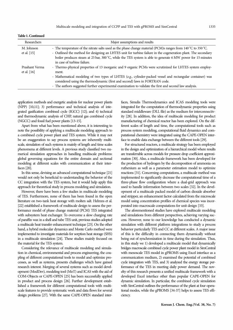
Table 1. ContinuedResearchers Major assumptions and results
M. Johnsonet al. [15]
- The temperature of the nitrate salts used as the phase change material (PCM)s ranges from 140 oC to 350 oC.- Outlined the method for designing an LHTES unit for turbine failure in the cogeneration plant. The secondary
boiler produces steam at 25 bar, 300 oC, while the TES system is able to generate 6 MW power for 15 minutesin case of turbine failure.
Prashant Vermaet al. [16]
- Thermo-physical properties of 13 inorganic and 9 organic PCMs were scrutinized for LHTES system employ-ment.
- Mathematical modeling of two types of LHTES (e.g., cylinder-packed vessel and rectangular container) wasconsidered using the thermodynamic (first and second) laws in FORTRAN code.
- The authors suggested further experimental examination to validate the first and second law analysis.

1336 J. H. Chang et al.
July, 2021
PROBLEM FORMULATION
As electricity is produced, it is concurrently consumed. This is acharacteristic of electricity that presents issues of stability and qualitywhen there is a disparity in demand and supply of power. There-fore, it is very important to maintain balance at varying demand.As seen in Fig. 1, power demand varies from time to time and sodoes its price due to the cost of production. During high demandfor power that is peak period, supplementing base load power plantsbecomes necessary, which comes at a higher cost from the powersuppliers than the average demand. Instead of augmenting withanother power generation system, the approach of storing electric-ity during the night time and reinserting it during the peak peri-ods offers a huge potential to reduce the total generation cost. FromFig. 1, energy usage is far below the baseline supply between the
Fig. 1. Global power demand in a day for three countries showing their various loads: PJM is the US electricity market [38].
Fig. 2. Schematic diagram of combined cycle with TES system and detailed unit processes: (a) Combined cycle with TES, (b) two-tank TESsystem.
hours of 1 and 9 for all the load curves and higher from hours of 9to 23. Hence, storing the excess energy during low demand hoursat base load operations can be used to augment the higher demandat peak load. For example, the base load operation provides about22% excess energy supply with reference to the actual demand atthe 6th hour on the PJM load curve and about 25% less at the 11th
hour during peak load. With the concept of this study, the excessenergy of the base load operation at the 6th hour can be stored andused at the 11th hour to increase the 70% baseline supply to about80%. This study thus proposes a combined cycle (CC) power plantwith thermal energy storage (TES) for this implementation.1. Performance Analysis
Typically combined cycle power plants consist of a gas turbineand a steam turbine which operate under the thermodynamic cyclesof Brayton and Rankine, respectively. After completing the first

Multiscale modeling and integration of CCPP and TES with gPROMS and SimCentral 1337
Korean J. Chem. Eng.(Vol. 38, No. 7)
cycle (Brayton), the high temperature working fluid that would haveescaped through the exhaust is captured by a heat recovery steamgenerator (HRSG) to generate steam. The steam is then released tothe steam turbine (second cycle) for additional power generation,and the low-temperature liquid ends up in the condenser where itis recycled to start the whole combined cycle.
The TES system is a two-tank storage unit with molten salt asthe thermal storage material (TSM) designed to store excess energyduring low demand of power for later use. It consists of a hot andcold tank to hold molten salt at high and low temperature, respec-tively. To this purpose, they are well insulated to minimize the lossof heat to the environment.2. Multiscale Modeling of Unified Framework
There are various computational tools for modeling and repli-cating chemical engineering processes. Of these are process simu-lators capable of simulating mathematical models of different orderof magnitude in the spatial and temporal scales. The complexity ofthese mathematical models requires sophisticated computationalstrategies to carry out the simulations. Hence, multiscale modelingbecomes relevant not only to replicating the physical processes butoffering insights into the real behavior of the process units.
In the multiscale computing environment, the concept of multi-scale modeling has a few unresolved questions, although it is largelyused in most fields of science. The questions range from terminol-ogy to general approach or technique in modeling a multiscale sys-tem and computations. There are different schools of thought amongresearchers in different research communities, basically because ofhow multiscale is perceived. Interestingly, the terms used in thesefields could mean the same thing, while others may be quite dif-ferent based on the field.
However, there are a few researches [39-42] with a methodolog-ical approach to the multiscale concept. In pursuit of commongrounds on multiscale modeling [43,44], proposed a possible ap-proach. The authors formulated a multiscale modeling and simu-lation framework which defines multiscale as a group of single-scale models interconnected through a modeling language or scalebridging methods. These bridging methods are the heart of multi-scale modeling, especially when different computational tools are
involved in its simulation. Popular among the computational com-munity in chemical engineering over the years is CAPE-OPEN.
While CAPE-OPEN standard interface in combination with otherprocesses [26,27,45] has achieved great results, its challenges can-not be overlooked. This study sought an alternative in couplingmeso-macro scales of different computational tools for dynamicsimulation. We leveraged the visual basic option in Excel, a commonand easy-to-use software as the communication channel betweenthe different scales of gPROMS and SimCentral for dynamic sim-ulation, which is not found in any research field. Not only was thedata exchange feasible, but there was no spike in computationaldemand for the multiscale unified framework simulation [43,44].gPROMS and SimCentral computational tools used in this studyare capable of modeling and simulating processes in steady anddynamic states. gPROMS comes with a wide scope of numericalsolvers for detailed mathematical modeling of process systemsranging from zero to two dimensions where numerical analysis ofpartial differential-algebraic equations can be handled. SimCentral,on the other hand, provides the flexibility to carry out process simula-tions roughly from a unit process to an entire process like Aspenplus, Pro II and others. It is widely used in the chemical engineer-ing community for dynamic simulation.3. TES Modeling Approach
TES is a technology widely employed to store excess thermalenergy and used at later times. The technology ranges from differ-ent concepts on how the energy is stored and the kind of materialsused. Among the TSMs, molten salt is used due to its high energycapacity storage from sensible heat. This study thus used it to bal-ance the hourly supply and demand for energy in the CC opera-tions. It was the mesoscale model for the CC integration simulationwhich provided internal insights into the dynamic behavior of heatloss during operation. As the TES interacts with the CC duringsimulation, the hot tank section charges for three hours during excessproduction at base load operation, stores high-temperature TSMfor six hours, release the energy to the CC for eight hours duringpeak load demand and then the low-temperature TSM return tocold tank section, which takes seven hours. During storage peri-ods in the hot and cold tanks, the gPROMS simulation provides
Fig. 3. Molten salt two-tank thermal energy storage system – heat flows influenced by temperature gradient. (a) Hot tank, (b) schematic dia-gram of heat transfers, (c) cold tank.

1338 J. H. Chang et al.
July, 2021
the rate of heat loss through the various sides of the tank as well asduring charging and discharging to the CC with the SimCentral.The hot tank part of the TES can be modeled as the mirror imageof the cold tank for the integrated system simulation.
The gPROMS ProcessBuilder chosen for the mesoscale model-ing of the two-tank TES system is an advanced process environ-ment that enables one to build models, validate and execute steady-state and dynamic simulations. By sectioning the whole storagetank into submodels, the basic models of heat transfer such as con-duction, convection and radiation were used to evaluate the high-temperature molten salt tank exposed to the surroundings.
The modeling of the tanks shown in Fig. 3 followed the meth-odology proposed by Zaversky et al. [46]. Fig. 3(a) and (c) are thehot and cold tanks, respectively, which shows the heat transferinside the tank and with the surroundings. Since the temperatureinside the two tanks is higher than the surroundings, heat loss isexpected through the mechanism, as shown in Fig. 3(b). The mol-ten salt, molten salt composition (60% NaNO3 and 40% KNO3),which is the most used sensible heat TSM in solar power plants,was chosen for this study considering its wide range of tempera-ture making it suitable for the combined cycle power plant operat-ing temperature. Full properties can be found in Table 3. The moltensalt exchanges heat via convection with the inner walls of the tank,bottom, the atmospheric gas and the surrounding.
With the sub-models, the study considered transient behaviorof the molten salt (1), tank’s atmospheric gas (2), tank walls (31)and insulation (6), the roof (3t) and insulation (4), different mate-
rials of the bottom (3b, 8, 9) and the tank surroundings (5,7). Themolten salt as well as the atmospheric gas region can be evaluatedwith the global mass and energy balances taking into considerationits interaction with the sub-models at their interfaces. One dimen-sional conduction heat transfer of multiple material layers wasmodeled for the tank roof, walls and the bottom. The wall wasmodeled as cylindrical while the roof and the bottoms as planarconduction heat transfers. On the interfaces where the sub-modelsinteract, convection models between the molten salts, tank walls,roof, bottom, atmospheric gas and the tank surrounding wereconsidered. Also, the radiation models were evaluated between theatmospheric gas, unwetted walls, roof, molten salt and the surround-ings. These make the complete mesoscale model of the TES tank,which is computed with the gPROMS advanced tool.
The mathematical description of the TES storage unit is pre-sented in Table 2 based on the assumptions mentioned above. Themass and energy balance (Eq. (5) and Eq. (6)) include time deriva-tives, which are differential equations. On the other hand, the heatsource terms, Eq. (7) and heat transfer equations Eq. (8)-Eq. (18)are algebraic equations. Since Eq. (9), Eq. (13) and Eq. (14) are non-linear terms, the resulting equations are a set of nonlinear differen-tial-algebraic equations (DAEs). By gPROMS solving approach,this can be represented by the below equations [47].
(1)
(2)
where x and y are n and m dimensional vectors of variables,
f x', x, y, t 0
g x, y, t 0
Table 2. Rigorous conservation and other closure mathematical modeling for TES systemDescription Mass/Energy transfer type Formula
Molten salt model Mass balance
Energy balance
Conduction=d:
Convection=v: Radiation=:
(5)
(6)
(7)(8)(9)
(10)
(11)(12)
(13)
(14)Lateral side172
Through the verticalwalls to the outside
(15)(16)
Topside15
Inside the tankThrough the tank’s top surface
(17)
The bottom side19
Inside the tankThrough the bottominsulation into the soil
(18)
dmdt-------- m· in m· out
cpVdTdt------- m· in hin m· out hout Se
Se q12v
q12
q13, lv
q13, bv
qijv
hiAi Tj Ti
qij
Ai Ti4
Tj4
qijd
kiAi
li--------- Ti Tj
qijv
hivAj Ti Tj
qij
Aj Ti4
Tj4
Rijd
rj
ri---
ln
ij
n
/ 2kili , Rij
1
2hivrjli
-----------------
ij , Rij
12hi
rrjli
-----------------
hij
Ti + Tj Ti2
+ Tj2
q17 q13, lv
q36, ld
q67d
q67v
q67
qsun
q27 q23, lv
q36, ld
q67d
q67v
q67
qsun
q15 q12v
q12
q23, rfv
q34, rfd
q45d
q45
q45v
q32, rf
qsun
q19 q13, bv
q38, bd
q89, bd

Multiscale modeling and integration of CCPP and TES with gPROMS and SimCentral 1339
Korean J. Chem. Eng.(Vol. 38, No. 7)
respectively, t is the independent variable and x' is the derivative ofx with respect to t. f and g are n and m dimensional systems ofequations.
In gPROMS, the backward differentiation formulae (BDF) wereemployed with a predictor and corrector step to solve the DAEsdescribed in Table 2. The k-step BDF method on the nth integra-tion step can be represented as [47]:
(3)
where hn is an integration step length, k, k are BDF coefficientand k, n is the accumulation of history terms in the BDF method.When this is substituted into the DAEs Eq. (1), the equation sys-tem becomes
(4)
This is a set of nonlinear equations, which can be solved usingNewton’s family method. To obtain accurate solutions, absoluteand relative tolerance were set to 105 in the gPROMS software forsimulation.
Since the hot and cold tanks work in reverse to each other atevery mode, as explained in section 2.4, the mathematical modelsgoverning their behavior are similar as provided in Table 2 exceptfor the rate of flow. Refer to [6,46] for a detailed explanation.4. Operation Scenario of Combined Cycle with TES
The operation modes of the integrated system are shown in Fig.4(a) charging mode, (b) normal/Storing mode, (c) discharging mode.Each line in Fig. 4(b) can be adjusted to normal, charging, dis-charging, and storage modes. And Mode (a)/(b)/(c) are manipu-lated by flow control of heat source.
(a) Thermal charging mode: Low-temperature TSM from thecold tank gains heat by transfer from part of the steam flowing intoIP ST through the heat exchanger and is stored in the hot tank.The resulting low-temperature steam is transported to the LP ST.
(b) Normal/storing mode: In these operation modes, there is noheat exchange between the CC and TES system since the full steamis utilized by the steam turbines. However, in normal mode, TSM
is held in the cold tank, whereas in the storing mode, the hightemperature TSM charged by the steam is stored in the hot tank.
(c) Discharging mode: High-temperature TSM from the hot tankaugments the energy capacity of the steam from the IP ST throughheat exchanger before it is transported to the LP ST. This increasesthe power generation of the steam turbines and the resulting low-temperature TSM is stored in the cold tank.
SOLUTION STRATEGY
1. Simulation BasisThe physical properties of the TSM used in this study are shown
x'n 1
hnk---------- kxn jxnjk
j0
k1
1
hnk---------- kxn k, n
f 1hnk---------- kxn k, n , xn, yn, tn
Fig. 4. Schematic diagram of CC with two-tank TES illustrating the different operation modes: (a) Charging mode, (b) storing or nomalmode, (c) discharging mode.
Table 3. Properties of molten salt used as cold and hot thermal stor-age material [49,50]
Type Active typeComponents 60% NaNO3-40% KNO3
Freezing temperature (K) 493Stabilizing temperature (K) 873Density (kg/m3) 1,899Viscosity (cP) 3.26Specific heat (J/kg-K) 1.495Heat of fusion ((kJ/kg) n/a
Table 4. Modeling and simulation basis for combined cycle withTES system [48,51]
System Modeling basis ValueTES Thermal saving and adiabatic efficiency 99%GT Adiabatic GT efficiency 89%
Pressure ratio 19.37Turbine inlet temperature 1,690.3 KTurbine outlet temperature 1,117.5K
ST Adiabatic HP ST efficiency 92%Adiabatic IP ST efficiency 91%Adiabatic LP ST efficiency 93%

1340 J. H. Chang et al.
July, 2021
in Tables 3 and 4, which are the modeling basis of CC with theTES process. The modeling basis is referenced from CC’s NETLreport [40] to ensure reliability and validity. In addition, the ther-modynamic model used in this study assumed an incompressiblefluid for TSM with the SRK state equation, which is widely usedfor hydrocarbons.2. Strategy for Multiscale Modeling of the Unified Framework
The SimCentral software is capable of steady and dynamic sim-ulation. However, since the process simulator is a black box model,which is usually applicable to integrated processes, developing adetailed model for heat loss analysis of the TES system is a limita-tion. With the aid of gPROMS software, a detailed mathematicalmodel of the TES was developed and simulated simultaneouslywith the SimCentral software where data are exchanged.
While the SimCentral model of the combined cycle with theTES system integration performed dynamic simulation under fouroperating conditions, the gPROMS analyzed the thermal efficiencyof the two-tank TES. In addition, the Excel interface for the dataexchange was constructed to enable the time synchronization andco-simulation of the two simulators for the multiscale model. Thedynamic simulation was carried out at a 1-second interval in thetwo dynamic simulators.
The execution strategy of multiscale modeling and the dynamicsimulation implemented in this research as shown in Fig. 5 is asfollows.
• In charging mode, the steam flowing to the ST in the SimCen-tral model splits into two where one goes to the TES system.This steam stream (1) exchanges heat with the cold moltensalt (1a) which gets charged (1b) and is stored in the hot tank.In the meantime, the Excel interface is set online enabling thetransfer of TSM properties from SimCentral to gPROMS simul-taneously for heat loss analysis. The resulting steam to the STgoes to the IP ST at a reduced temperature due to heat loss.
• The storing mode generates power in the same capacity asthe normal mode in SimCentral. At these modes, the Excelconnection is set offline. In the meantime, SimCentral simu-
lates the macroscale model of the CC while gPROMS ana-lyzes the rate of heat loss of the TS in the tank. At storingmode, the charged molten salt is held in the hot tank and atnormal mode, the low-temperature molten salt is kept in thecold tank.
• In discharging mode, the power generation capacity of theplant increases as the steam flowing into the ST gains energyfrom the molten salt (3a) through the heat exchanger and theresulting molten salt (3b) is stored in the cold tank. While theheat exchange takes place, the Excel interface comes online toenable the communication between SimCentral and gPROMSfor the dynamic simulation. In this mode, the resulting steamflowing to ST goes to LP ST in the SimCentral model.
This co-simulation of an integrated system provides insight intothe behavior of the plant at different spatial and temporal scales.While the SimCentral model offers an overall dynamics of the sys-tem, the gPROMS helps to zoom into the behavior of the TES at adetailed level in terms of how the heat is lost and which part con-tributes the most of the losses. This can be applied to simulationsof complex processes where one is interested in the detail dynam-ics of a certain unit. However, this can be of a huge computationalburden as well as time lag when several individual units are to bemodeled together.
RESULT AND DISCUSSION
1. Process Flow Diagram of CC with TES Based on the UnifiedMultiscale Framework
Fig. 6 shows the process flow diagram of CC with TES in SimCen-tral. The integration process enabled SimCentral software to per-form dynamic simulation of CC and TES for four different opera-tional modes (see Fig. 4). The process includes the main equip-ment (GT, ST, TES) shown in Fig. 2. The TES system was mod-eled to accept values from gPROMS via the black box system inSimCentral.
Fig. 7 shows a close view process flow diagram of the two-tank
Fig. 5. Unified framework showing how the excel interface communicate with the macroscale model in SimCentral and mesoscale model ingPROMS at the various operations modes.

Multiscale modeling and integration of CCPP and TES with gPROMS and SimCentral 1341
Korean J. Chem. Eng.(Vol. 38, No. 7)
Fig. 6. Integrated combined cycle with a two-tank TES system process flow diagram. A strategy to deal with varying daily power demand.
Fig. 7. gPROMS simulator for two storage TES tank process flow diagram within detailed mathematical modeling.

1342 J. H. Chang et al.
July, 2021
TES system. Its performance was analyzed through detailed math-ematical modeling of mass and energy conservation laws and heattransfer using the gPROMS software. The framework was able tosend and receive data such as steam and TSM flow rate, tempera-ture between the integrated system. While these properties changeat the various operating modes, the integrated system is config-ured for time synchronization to enable smooth communicationin the dynamic simulation.
Fig. 8 shows the Excel interface developed to serve as a scalebridge for the multiscale modeling and simulation of CC withTES. In the Excel interface, SimCentral and gPROMS exchangedata in the same time zone by clicking the button of each modealong with the user selecting the time corresponding to each oper-ating process. As data is interchanged during the simulation, theamount of change in power generation, the heat loss and efficiencyof the TES tank are calculated in real-time, and the results areshown in the Excel interface as a chart.2. Performance Analysis
Fig. 9 shows the variation of power generation by IP ST and LPST for three hours charging and six hours discharging when thenormal and saving time is nine hours and six hours accordingly.As a base case, we employed an operation time of three hours forcharging, six hours for storing, eight hours for discharging andseven hours for normal mode as summarized in Table 7. Duringcharging mode, 39.3 MW of thermal energy was stored in the TEStank. During discharge, 7.3 MW of thermal energy was released to
LP ST by the TES tank. In conclusion, the average TES efficiencywas 99.66%.
The mass balance of the two-tank TES with a CC is presentedfor four operational modes in Tables 5 and 6 based on Fig. 2.Table 5 shows the heat and material balance of the two-tank TESin storing/normal mode. Since TES is disconnected from the CC(see Fig. 4(b)), both modes share the same heat and material bal-ance. These modes correspond to the normal operation of a CCwithout TES. However, there is a difference in view of TES. Whilethe storing mode saves thermal energy in TES through the charging
Fig. 8. Excel graphic user interface and dynamic control panel as a scale bridge for data and time synchronization between SimCentral andgPROMS simulator.
Fig. 9. Various power generation of IP and LP ST for four modesbased on daily power.

Multiscale modeling and integration of CCPP and TES with gPROMS and SimCentral 1343
Korean J. Chem. Eng.(Vol. 38, No. 7)
mode, the normal mode releases thermal energy through discharg-ing mode.
TES for the charging and discharging modes are shown inTable 6 based on Fig. 2(b). The thermal power stored during chargingis 38 MW for hot tank in the CC with TES. In discharging mode,the steam from IP ST obtained thermal energy from TES, whichresulted in increasing the outlet steam temperature to LP ST. Thethermal power released for the inlet steam to LP ST can be calcu-lated in consideration of the thermal efficiency of the TES tankTable 4.
The total power generation of a reference CC without TES was466.7 MW [48]. In this study, we assumed GT and HP ST as notconnected to the TES system. To evaluate the performance of theTES, the efficiency of IP and LP ST, defined as the ratio of totalpower generation with TES to the total power generation withoutTES for 24 hours, was calculated as follows:
(15)
where t is the TES efficiency of IP and LP ST, j=charging, stor-
ing, discharging and normal mode.Fig. 10 represents the heat loss results of the molten salt as its
level rises in the cold and hot tanks during the charging and dis-charging modes. With the increasing surface of the wetted area inthe two tanks, the heat loss through the side walls consequentlyincreases. Contrarily, the non-wetted area of the tanks reduces, whichtranslates into the heat transfer contribution by radiation. How-ever, since the conduction heat transfer through the bottom of the
t 1
tday PIP PLP ------------------------------- tj PIP, j PLP, j
j 100
Table 5. Heat and material balance of combined cycle with TES system for storing or normal operational modeStream No. 1 2 3 4 5 6
Description FromGT
FromIP RH
ToIP ST
FromIP ST
ToLP ST
ToStack
Temperature (K) 876.0 0,838.9 0,838.9 525.3 525.2 418.2Pressure (KPa) 104.8 2,302.8 2,302.8 241.3 231.3 097.8Flow rate (kg/s) 592.8 0,126.3 0,126.3 116.9 116.9 592.8Mole CompO2 0.12 0 0 0 0 0.12N2 0.73 0 0 0 0 0.73CO2 0.04 0 0 0 0 0.04H2O 0.11 1 1 1 1 0.11
Table 6. Heat and material balance of combined cycle with TES system for charging and discharging operation modeTES
Operation modeStream No. A1 A2 A3 A4 A5 A6 A7 A8 5A
Description FromIP RH
ToLP ST
FromCold tank
ToHot tank
FromIP ST
ToLP ST
FromHot tank
ToCold tank
ToLP ST
Charging
Temperature (K) 0,838.5 518.7 550.0 830.0 n/a n/a n/a n/a 521.2Pressure (KPa) 2,302.7 241.3 107.0 107.0 n/a n/a n/a n/a 231.3Flow rate (kg/s) 0,060.6 060.6 94. 94. n/a n/a n/a n/a 116.9Mole CompH2O 1 1 0 0 1 1 0 0 1TSM 0 0 1 1 0 0 1 1 0
Discharging
Temperature (K) n/a n/a n/a n/a 524.2 580.2 800.0 550.0 580.2Pressure (KPa) n/a n/a n/a n/a 231.3 229.6 101.0 101.0 229.6Flow rate (kg/s) n/a n/a n/a n/a 116.9 116.9 35. 35. 116.9Mole CompH2O 1 1 0 0 1 1 0 0 1TSM 0 0 1 1 0 0 1 1 0
Table 7. Total various power generation and efficiency of combinedcycle with thermal energy storage system for four modes
Operation mode Charging Storing/normal DischargingOperation time 3 hours 6 hours/7 hours 8 hoursGT 272.3 MWHP 47.0 MWIP+LP 108.1 MW 147.4 MW 154.7 MWTotal 427.4 MW 466.7 MW 474.0 MWEfficiency 98.31%

1344 J. H. Chang et al.
July, 2021
tanks is not influenced by the levels of the molten salt, it remainsthe same at approximate values of 2.6 kW and 4.6 kW for the coldand hot tanks, correspondingly. The trend shown by the curves inthe figure above is of close agreement with the results of Schulte-Fischedick et al. [52] while the difference in values can be attributedto geometry used. This was expected because the hot tank is at ahigher temperature than the cold tank. The contrasting effects ofheat loss contributions through the top and the side walls of thetanks nearly gave constant overall heat loss. The three hour chargingof the hot tank at a flowrate of 94 kg/s slightly increased in heat lossfrom 23.4 kW to 28.8 kW while that of the cold tank increasedfrom 13.3 kW to 19.3 kW for 8 h filling time at a flowrate of 35kg/s. Hence, heat loss of approximately 48 kW is incurred duringthe charging/discharging mode of CC with TES which is 0.01% ofthe total power produced by the plant.
Fig. 11 shows the molten salt cool down curves for both hotand cold tanks at full load. From the operation strategy of the CCwith TES, the storing and normal mode for this study is 6 h, which
Fig. 10. Heat losses through the different sides of the tanks as the molten salt level increases during filling. (a) 3 h charging time of hot tank,(b) 8 h filling time of cold tank.
Fig. 11. Molten salt temperature drop of the two-tank thermal energystorage during the 6 h storing/normal mode. (a) Hot tank,(b) Cold tank.
Table 8. Parametric study and efficiency analysis of different opera-tion modes depend on discharging operating time withindifferent flow rate from hot tank to cold tank
Operating time (h) Case 1 Case 2 Case 3Charging 3 3 3Storing 6 6 6Discharging 6 8 10Normal 9 7 5Efficiency 98.1% 98.3% 98.5%
was chosen based on Fig. 1. A short while into these modes, thesimulation showed constant temperature difference for the period,which is clearly seen in Fig. 11. The heat loss contribution throughthe bottom remained constant, while that through the non-wet-ted and wetted walls showed slight changes.
This is because the level of the molten salt was constant andhence no change in areas for wetted side walls and non-wetted walls.Consequently, hourly temperature drop rates of 0.04 K and 0.06 Kwith a corresponding approximated heat loss of 19.3 kW and28.7 kW were obtained in these operation modes for the cold andhot tanks. With the heat loss rate in the two tanks, an average effi-ciency of 99.95% can be expected for the duration in the storingand normal modes.
For the entire operation modes, the study obtained efficienciesof 99.69% for the cold tank at a temperature drop rate of 0.1 Kand 99.63% for the hot tank with 0.18 K cool down rates. Moreenergy was lost during discharge followed by the storing mode.The charging mode contributed the least to heat loss.
However, the heat loss rate during discharge was higher for thecold than the hot tank. This was as a result of the differences in themolten salt flow rates. A similar trend was observed in the chargingmode for the two tanks that are higher flow rates yielded moreheat loss.3. Parametric Study and Thermodynamic Analysis
Three case studies on discharging time of TES were conducted

Multiscale modeling and integration of CCPP and TES with gPROMS and SimCentral 1345
Korean J. Chem. Eng.(Vol. 38, No. 7)
in reference to the daily power demand shown in Fig. 1. To effec-tively deal with the irregular peak load demand and understandthe performance of the TES system, dynamic simulation at vary-ing discharge time was carried out and the results are summarizedin Table 8.
The power generation was 156.4 MW, 154.7 MW, and 153.9MW for the three cases. Corresponding efficiencies using Eq. (15)were computed obtaining 98.10%, 98.30% and 98.50%. These resultsas Fig. 12 and Table 8 display imply that with a small loss of effi-ciency, the operation time for discharging can be flexibly adjustedaccording to power demand. Finally, the power generated in thethree cases as illustrated in Fig. 9 give an insight into the behaviorof the TES system during discharging mode.
Fig. 13 shows a T-S diagram of the Rankine cycle with three-stage ST consisting of HP, IP and LP.
The main characteristics of the T-S diagram are as follows [43]:• Process (A)-(B): Water is heated at the economizer in HRSG.
The details of this step are captured in Fig. 2(a).• Process (B)-(C): The line (B)-(B') is for phase change from
liquid water to vapor. (B') is the saturation point. This stepoccurred at the LP, IP, and HP steam boiler in Fig. 2(a). The
line from (B) to (C) describes the superheating process ofwater vapor.
• Process (C)-(E)-(A): There are two routes for this process:(C)-(D)-(E)-(A) for charging and storing/normal mode and(C)-(D)-(D’)-(E)-(A) for discharging mode. As discussed, theformer corresponds to a T-S diagram for a conventional Ran-kine cycle. Line (C)-(D) denotes the process from IP RH toLP ST. The IP steam generated the power at IP ST and theexhaust steam was sent to LP ST, which corresponds to streams3, 4 and 5 in Table 5. Line (D)-(E) represents the step fromLP ST to condenser and power generation at LP ST duringcharging or storing/normal mode as demonstrated in Fig.7(a) and (b). This is also the case even for a conventional ST.
However, careful attention should be made to the process (D)-(D')-(E) since this explains the additional power generation duringthe discharging model with TES. Point (D') means the LP steamwas reheated in the discharging mode and the temperature roseaccordingly. This situation was quantified in Table 6 through streamA5 and A6 in this paper. The area with red stripes is the driving forceto increase the power generation by supplying thermal energy fromTES during discharging mode. The principle used in this studycan be employed when HP ST relates to TES in a CC.
• Process (E)-(A): This process explicated the steam flow fromLP ST to HRSG, and the vapour was condensed into liquid water.As a result, a T-S diagram allowed a qualitative thermodynamicinterpretation for TES with a CC. From the observation of Fig. 13,TES is applicable not only with a CC but also with other powergeneration plants, such as CSP and NPP, when operation and designconditions are satisfied.
CONCLUSION
The study explored the feasibility of integrating a combined cyclepower plant with a TES system. This is relevant to meeting the vary-ing daily demand for electricity by utilizing an existing power gen-eration plant. To this purpose, a multiscale model was developedwhereby TES was integrated to augment the energy production ofCC during the higher demand by storing energy at low demandof power, as shown in Fig. 3. The transient behavior of the inte-grated system was simulated with SimCentral to ascertain the per-formance and usefulness of TES. While SimCentral does well toprovide process insight into the entire plant, it was necessary toassess the effectiveness of the two-tank TES system in terms ofenergy loss. SimCentral could not provide those details because itsmodels are black-box type. In this light mesoscale two-tank TESwas modeled with gPROMS which was coupled with SimCentralusing a developed excel interface in this research. That ensuredcommunication between the macroscale model of CC and themesoscale model of the two-tank TES for the dynamic simulationand time synchronization.
The power generated by the CC without TES was 466.7 MW,which was reduced to 427.4 MW when the TES was set online incharging. This in effect increased the power production to 474.0MW when the energy stored in the TES system was released tothe steam turbines. It implies that the 3-hour charging of the TSMcaused the CC to lose 39.3 MW of power; however, 7.3 MW was
Fig. 12. Power generation of IP and LP ST with TES based on threedifferent discharging times (Case 1: 6 hour discharging, case2: 8 hour discharging, case 3: 10 hour discharging).
Fig. 13. T-S diagram of Rankine cycle: line (A)-(B)-(C)-(D)-(E) is CCwithout TES at the various operation modes while line (A)-(B)-(C)-(D)-(D')-(E) is CC with TES at only dischargingmode.

1346 J. H. Chang et al.
July, 2021
added to its original production capacity after 8-hour discharge ofthe TSM energy to the steam stream. Also, we conducted a para-metric study on different discharging times of the TSM to get aninsight into the varying daily demand for electric power. In theanalysis, discharging times of 6 and 10 hours generated additionalpower of 9.0MW and 6.5MW, respectively. Comparing the CC inte-gration with TES to CC only, the maximum efficiency obtainedwas 98.5% and the minimum was 98.1%.
Through this study, we have successfully integrated the macro-scale combined cycle power plant and the mesoscale TES system.The dynamic simulation results of the presented detailed mathe-matical model were validated. The methodology of this researchfinding could present a research direction of processes requiringcoupling of various model scales between different computationaltools, such as detailed nuclear reactor design and integration pro-cesses in chemical engineering.
ACKNOWLEDGEMENTS
This work was supported by the Industrial Strategic TechnologyDevelopment Program-Engineering Core Technology DevelopmentProject (Project No. 201703220003, Development of basic designand FEED automation task support system based on Cloud system)funded By the Ministry of Trade, Industry & Energy (MOTIE, Korea).
NOMENCLATURE
A : area [m2]Cp : heat capacity [kJ/K] : emissivityh : heat transfer coefficient [Wm2K1]hin : inlet specific enthalpy [kJ/kg]hout : outlet specific enthalpy [kJ/kg]k : thermal conductivity [Wm1K1]m : mass [kg]min : inlet mass flowrate [kg/s]mout : outlet mass flowrate [kg/s]q : energy [kJ]R : heat transfer resistancer : radius [m]T : temperature [K]t : time [s]V : volume [m3] : density [kg/m3] : Stefan Boltzmann constant [kgs3K4]x : n dimensional vectors of variablesy : m dimensional vectors of variablesx' : derivative of x with respect to tf : n dimensional systems of equationg : m dimensional systems of equationhn : integration step lengthk, k : BDF coefficientk, n : accumulation of past history terms in the BDF method
AbbreviationsCC : combined cycle
TES : thermal energy storageCHP : combined heat and powerCSP : concentrating solar powerPCM : phase change materialNPP : nuclear power plantsIGCC : integrated gasification combined cycleNGCC : natural gas combined cycleNPP : nuclear power plantsSHS : sorption heat storageModDev: model developmentMoT : modeling toolHRSG : heat recovery steam generatorTSM : thermal storage materialGT : gas turbineST : steam turbineLP ST : low pressure steam turbineIP ST : intermediate pressure steam turbineHP ST : high pressure steam turbineHP ST : heat exchanger
Superscriptd : conduction : radiationv : convection
Subscriptb : bottomi, j : nodesl : lateral siderf : roof
REFERENCES
1. M. Khanna and M. D. Rao, Annu. Rev. Resour. Econ., 1, 568 (2009).2. M. Johnson, J. Vogel, M. Hempel, A. Dengel, M. Seitz and B.
Hachmann, Energy Procedia., 73, 281 (2015).3. Interactive Gas Turbine Portfolio Brochure, Siemens, https://assets.
new.siemens.com/siemens/assets/api/uuid:10f4860b140b2456f05d32629d8d758dc00bcc30/gas-turbines-siemens-interactive.pdf.
4. A. Rahman, A. D. Smith and N. Fumo, Appl. Therm. Eng., 100, 668(2016).
5. C. A. Cruickshank, Evaluation of a stratified milti-tank thermal stor-age for solar heating applications, PhD Thesis, Queen’s University(2009).
6. I. Rodríguez, C. D. Pérez-Segarra, O. Lehmkuhl and A. Oliva, Appl.Energy, 109, 402 (2013).
7. I. L. Garcia, J. L. Alvarez and D. Blanco, Sol. Energy, 85, 2443 (2011).8. C. Parrado, A. Marzo, E. Fuentealba and A. G., Fernandez, Renew.
Sustain. Energy Rev., 57, 505 (2016).9. L. Heller and P. Gauche, Sol. Energy, 93, 345 (2013).
10. C. Daniel, S. Natalie and F. Charles, Trans. Amer. Nucl. Soc., 116(2),837 (2017).
11. J. Edwards, H. Bindra and P. Sabharwall, Ann. Nucl. Energy, 96, 104(2016).
12. O. Maurstad, LFEE, 2005-002 WP (2005), https://sequestration.mit.edu/pdf/LFEE_2005-002_WP.pdf.
Multiscale modeling and integration of CCPP and TES with gPROMS and SimCentral 1347
Korean J. Chem. Eng.(Vol. 38, No. 7)
13. B. J. Alqahtani and D. Patiño-Echeverri, Appl. Energy, 169, 927(2016).
14. O. Garbrecht, M. Bieber and R. Kneer, Energy, 118, 876 (2017).15. M. Johnson, J. Vogel, M. Hempel, A. Dengel, M. Seitz and B.
Hachmann, Energy Procedia, 73, 281 (2015).16. P. Verma, Varun and S. K. Singal, Renew. Sustain. Energy Rev.,
12(4), 999 (2008).17. V. Vasilios, US Patent, 61,954,619 (2014).18. K. Drost, Z. Antoniak and D. Brown, Energy Conv. Eng. Con., 4,
251 (1990).19. M. K. Drost, Z. I. Antoniak, D. Brown and S. Somansundaram,
US. Dep. Energy, PNL-7403 (1990).20. W. Q. Tao and Y. L. He, IHTC 14. 8, 671 (2010), https://doi.org/
10.1115/IHTC14-23408.21. V. V. Krzhizhanovskaya, D. Groen, B. Bozak and A. G. Hoekstra,
Procedia. Comput. Sci., 51, 1082 (2015).22. A. Helmns and V. P. Carey, J. Therm. Sci. Eng. Appl., 10(5), 051004
(2018).23. M. Parsazadeh and X. Duan, Appl. Energy, 216, 142 (2018).24. M. Fasano, D. Borri, A. Cardellini, M. Alberghini, M. Morciano, E.
Chiavazzo and P. Asinari, Energy Procedia, 126, 509 (2017).25. J. C. Lee, O. S. Kofi, S. Y. Kim, S. G. Hong and M. Oh, J. Eng. Sci.
Technol., 10, 48 (2015).26. R. Morales-Rodriguez and R. Gani, Comput. Aided Chem. Eng.,
24, 207 (2007).27. R. Morales-Rodríguez and R. Gani, Comput. Aided Chem. Eng.,
26, 495 (2009).28. R. Morales-Rodríguez, R. Gani, S. Déchelotte, A. Vacher and O.
Baudouin, Chem. Eng. Res. Des., 86, 823 (2008).29. Z. Jaworski and B. Zakrzewska, Comput. Chem. Eng. 35(3), 434
(2011).30. P. Heidebrecht, M. Pfafferodt and K. Sundmacher, Chem. Eng. Sci.,
66(19), 4389 (2011).31. D. G. Vlachos, A. B. Mhadeshwar and N. S. Kaisare, Comput. Aided
Chem. Eng., 30(10-12), 1712 (2006).32. G. Pozzetti and B. Peters, Int. J. Multiph. Flow., 99, 186 (2018).33. H. M. Park, Int. J. Heat Mass Transf., 75, 545 (2014).34. D. H. Oh, R. Y. Jeon, J. H. Kim, C. H. Lee, M. Oh and K. J. Kim,
Cryst. Growth Des., 19(2), 658 (2019).35. N. D. Vo, M. Y. Jung, D. H. Oh, J. S. Park, I. Moon and M. Oh,
Combust. Flame, 189, 12 (2018).36. G. H. Lee, N. D. Vo, R. Y. Jeon, S. W. Han, S. U. Hong and M. Oh,
Korean J. Chem. Eng., 35(9), 1791 (2018).37. H. H. Lee, J. C. Lee, Y. J. Joo, M. Oh and C. H. Lee, Appl. Energy,
131, 425 (2014).38. Electrical energy storage, Technical Report, International Electro-
chemical Commission, http://www.iec.ch/whitepaper/pdf/iecWP-energystorage- LR-en.pdf (2011).
39. E. Weinan, B. Engquist, X. Li, W. Ren and E. Vanden-Eijnden,Commun. Comput. Phys., 2(3), 367 (2007).
40. G. D. Ingram, I. T. Cameron and K. M. Hangos, Chem. Eng. Sci.,59(11), 2171 (2004).
41. J. O. Dada and P. Mendes, Integr. Biol., 3(2), 86 (2011).42. A. Yang and W. Marquardt, Comput. Chem. Eng., 33(4), 822 (2009).43. A. Hoekstra, B. Chopard and P. Coveney, Philos. Trans. R. Soc. A
Math. Phys. Eng. Sci., 372(2021), 20130377 (2014).44. B. Chopard, J. Borgdorff and A. G. Hoekstra, Philos. Trans. R. Soc.
A Math. Phys. Eng. Sci., 372(2021), 20130378 (2014).45. S. E. Zitney, CAPE-OPEN integration for advanced process engi-
neering co-simulation, Final Report. DOE/NETL-IR-2007.46. F. Zaversky, J. García-Barberena, M. Sánchez and D. Astrain, Sol.
Energy, 93, 294 (2013).47. R. B. Jarvis and C. C. Pantelides, Robust dynamic simulation of
chemical engineering processes, PhD Thesis, Imperial College Lon-don University (1993).
48. W. Shelton and J. Lyons, Shell gasifier IGCC base cases, Report.NETL PED-IGCC-98-002 (2000).
49. T. E. Boukelia, M. S. Mecibah, B. N. Kumar and K. S. Reddy, Energy,88, 292 (2015).
50. R. I. Dunn, P. J. Hearps and M. N. Wright, Proc. IEEE, 100(2), 504(2012).
51. W. S. Lee, J. C. Lee, H. T. Oh, S. W. Baek, M. Oh and C. H. Lee,Energy, 134, 731 (2017).
52. J. Schulte-Fischedick, R. Tamme and U. Herrmann, Ameri. Soc. ofMech. Eng., 2, 515 (2008).