gas turbine combined cycle power system -...
TRANSCRIPT

40TH IIEE ANNUAL NATIONAL
CONVENTION AND 3E XPO 2015
SMX Convention Center, Mall of Asia Complex, Pasay City
November 25 - 28, 2015
IIEE@40: A Journey of Service for Excellence

Gas Turbine Combined Cycle
Power System
Technical Presentation
by
Engr. Enrique I. Flores, PEE
IIEE State of Qatar Chapter
What is a Gas Turbine
Combined Cycle?
A combined-cycle power plant uses both gas turbines and a steam turbine together to produce up to 50 percent more electricity from the same fuel than a traditional simple-cycle plant. The waste heat from the gas turbine exhaust routed directly to the heat recovery steam generator to produce steam and routed to the nearby steam turbine which generates extra power.

Combined Cycle Power Plant

GTCC Power System
1.) Fuel Tanks or Natural Gas Facility
2.) Black Start System
3.) Gas Turbine Units
4.) Heat Recovery Steam Generators
5.) Steam Turbine Unit
6.) Main and Auxiliary Transformers
7.) Local and Central Control Room
8.) Feed Water System
9.) Main Condenser
10.) Main Cooling Water System
11.) High Voltage Switchyard
12.) Other Balance of Plant (BOP)
Gas Turbine Combined Cycle
Efficiency
GAS TURBINE = 30 – 33%
COMBINED CYCLE = 20 – 25%
TOTAL NET EFFICIENCY = 50 – 60%

World Record
Highest Efficiency
The 600 MW Combined Cycle Power Plant Irsching 4 by Siemens achieved a world record highest efficiency of 60.75 (net) in May 2011 in Erlargen Germany

Bataan Combined Cycle
Power Plant Philippines
The 600 MW Combined Cycle Power Plant in Limay Bataan Philippines was the first of its kind in the Philippines commissioned in 1992 as a fast track project during the nation wide black-outs in our country due to lack of power plants to support the booming economy.
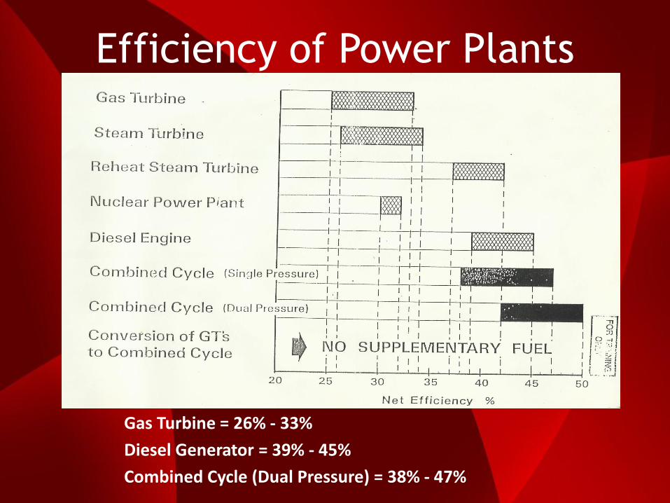
Efficiency of Power Plants
Gas Turbine = 26% - 33%
Diesel Generator = 39% - 45%
Combined Cycle (Dual Pressure) = 38% - 47%
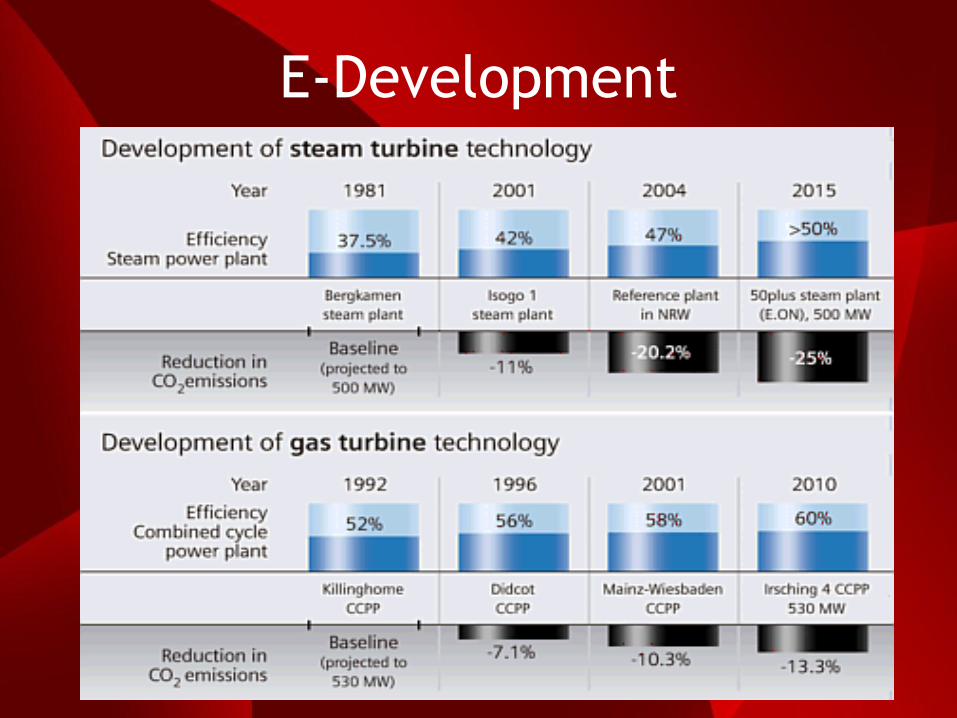
E-Development

FUEL SUPPLY SYSTEM
Standard Fuel for GT
1.) Jet A/Kerosene
2.) Natural Gas
3.) Distillate (including No.2
Fuel oil and Diesel oil)
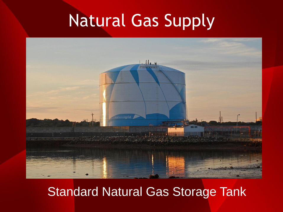
Natural Gas Supply
Standard Natural Gas Storage Tank
Natural Gas Supply
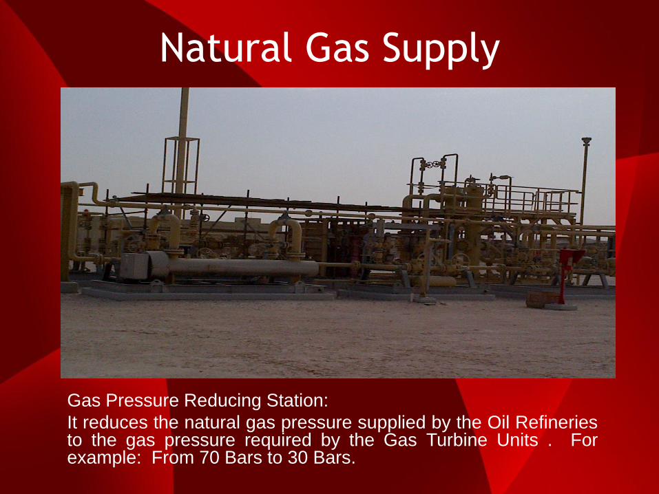
Gas Pressure Reducing Station:
It reduces the natural gas pressure supplied by the Oil Refineries to the gas pressure required by the Gas Turbine Units . For example: From 70 Bars to 30 Bars.

Natural Gas Supply
Japan is the highest importer of LNG.

Natural Gas Supply
Global gas imports is increasing fast.
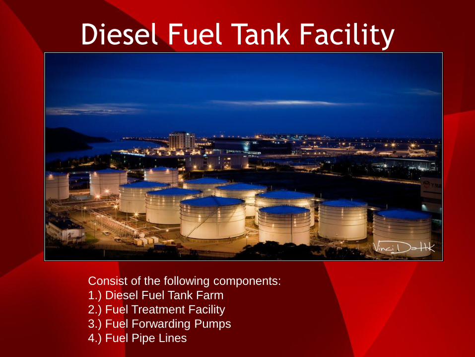
Diesel Fuel Tank Facility
Consist of the following components:
1.) Diesel Fuel Tank Farm
2.) Fuel Treatment Facility
3.) Fuel Forwarding Pumps
4.) Fuel Pipe Lines
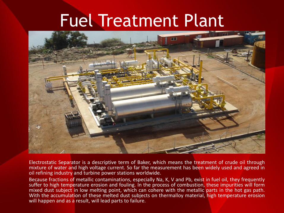
Fuel Treatment Plant
Electrostatic Separator is a descriptive term of Baker, which means the treatment of crude oil through mixture of water and high voltage current. So far the measurement has been widely used and agreed in oil refining industry and turbine power stations worldwide. Because fractions of metallic contaminations, especially Na, K, V and Pb, exist in fuel oil, they frequently suffer to high temperature erosion and fouling. In the process of combustion, these impurities will form mixed dust subject in low melting point, which can cohere with the metallic parts in the hot gas path. With the accumulation of these melted dust subjects on thermalloy material, high temperature erosion will happen and as a result, will lead parts to failure.

Diesel Fuel Tank
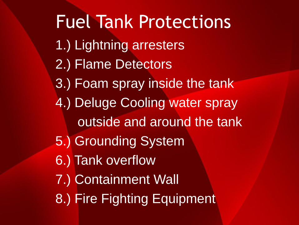
Fuel Tank Protections 1.) Lightning arresters
2.) Flame Detectors
3.) Foam spray inside the tank
4.) Deluge Cooling water spray
outside and around the tank
5.) Grounding System
6.) Tank overflow
7.) Containment Wall
8.) Fire Fighting Equipment

Deluge Fire Protection Skid
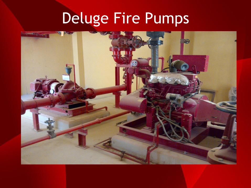
Deluge Fire Pumps
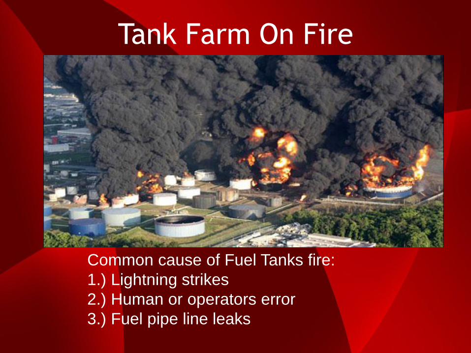
Tank Farm On Fire
Common cause of Fuel Tanks fire:
1.) Lightning strikes
2.) Human or operators error
3.) Fuel pipe line leaks

BLACK START SYSTEM
What is a Black Start System? It is the process of starting or restoring an electric power station to operation without relying on the external transmission network. This normally happens during total loss of power in the grid on a bad weather. In order to have a black start capability, most power plants have a dedicated diesel generator of 2MW to 5MW capacity called the Black Start Diesel Generator (BSDG), which can be used to restart back the first gas turbine generator and its auxiliaries back in service which will in turn provide enough supply of power to start the other remaining gas turbines to restore back the whole Power Plant during black out condition.
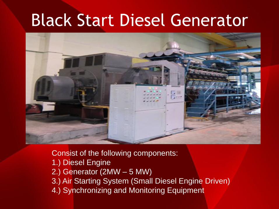
Black Start Diesel Generator
Consist of the following components:
1.) Diesel Engine
2.) Generator (2MW – 5 MW)
3.) Air Starting System (Small Diesel Engine Driven)
4.) Synchronizing and Monitoring Equipment

GAS TURBINE

What is a Gas Turbine?
A gas turbine, also called a combustion turbine, is a type of internal combustion engine. It has an upstream rotating compressor coupled to a downstream turbine, and a combustion chamber in between. The gas turbine is the heart of the power plant. A gas turbine is a combustion engine that can convert natural gas or other liquid fuels to mechanical energy which then drives a generator that produces electrical energy or power output.
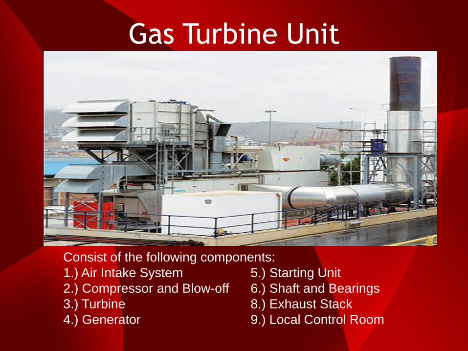
Gas Turbine Unit
Consist of the following components:
1.) Air Intake System 5.) Starting Unit
2.) Compressor and Blow-off 6.) Shaft and Bearings
3.) Turbine 8.) Exhaust Stack
4.) Generator 9.) Local Control Room

Gas Turbine Main Parts

Gas Turbine Unit
Combustion Chamber and Turbine
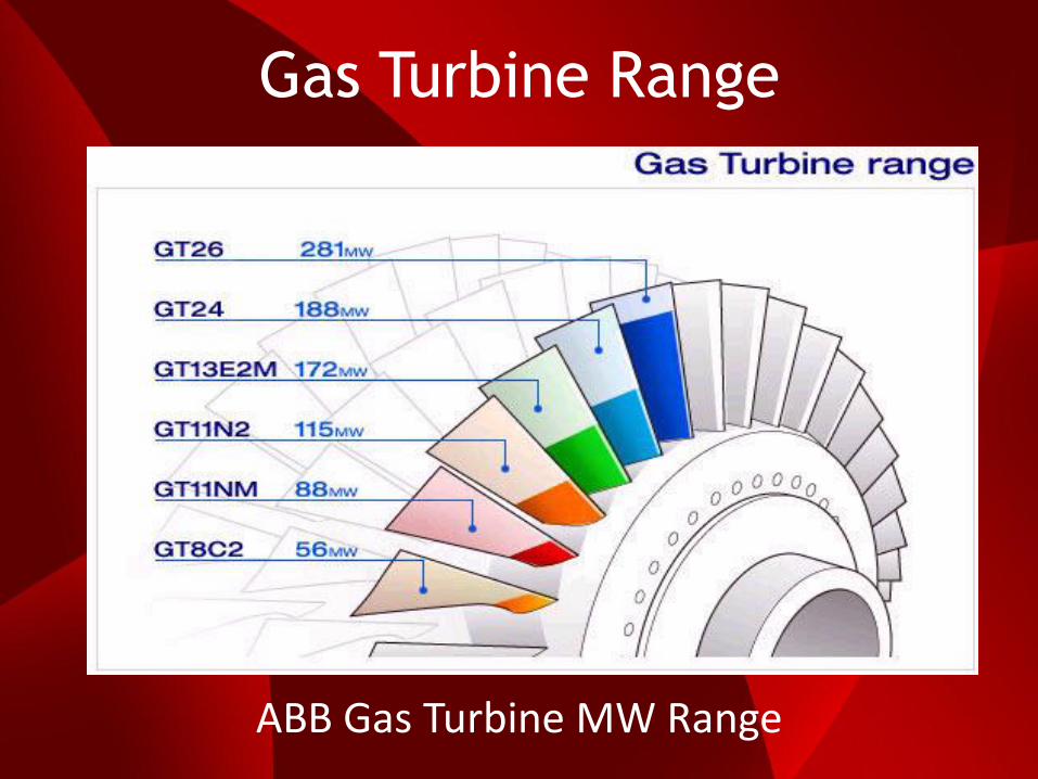
Gas Turbine Range
ABB Gas Turbine MW Range
33
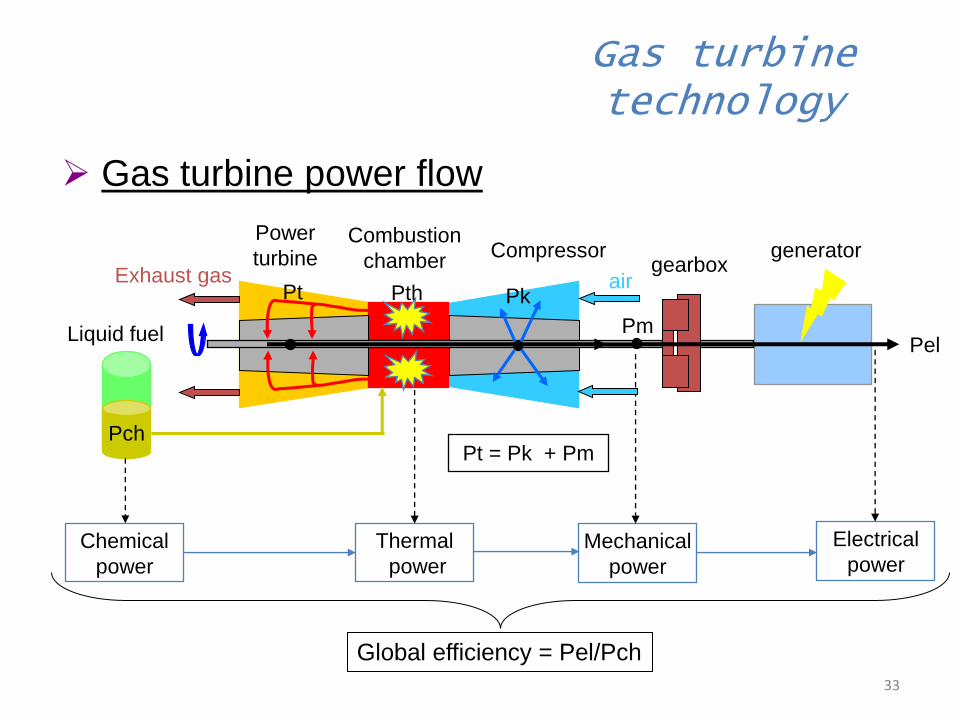
Pk
Pm Pel
Electrical
power Mechanical
power
Thermal
power
Chemical
power
Liquid fuel
Combustion
chamber Compressor
Power
turbine generator
air Pth
Pch Pt = Pk + Pm
Gas turbine technology
Pt
gearbox Exhaust gas
Global efficiency = Pel/Pch
Gas turbine power flow

Industrial Gas Turbine
Consist of the following main components:
1.) Inlet Air
2.) Compressor
3.) Combustion Chamber
4.) Turbine
5.) Exhaust

Gas Turbine compared to
4-stroke Engine
Admission Compression Combustion Exhaust
Consist of the following steps:
1.) Admission – Admits mixture of air and fuel in to the cylinder.
2.) Compression – Compressed air using stages of blades.
3.) Combustion – Mixed compressed air and fuel then ignited to produce mechanical work.
4.) Exhaust – Hot gas is being released to the exhaust stack or to the steam boiler.
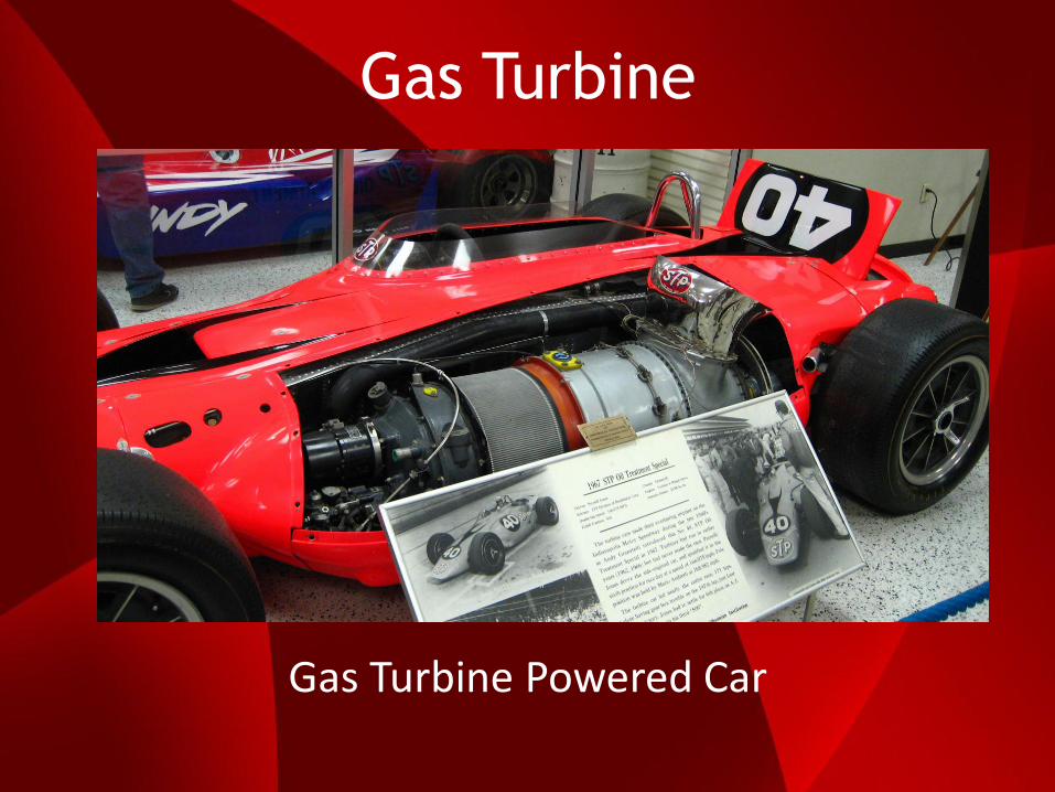
Gas Turbine
Gas Turbine Powered Car

Progress in blade metals

Gas Turbine Blade Damaged
Gas turbine rotor blades damaged by blade rubbing due to high vibrations. High vibrations can cause the rotor blades to rub against the turbine casing.

Gas Turbine Blade Metal
Nickel base super alloys are used in the most demanding portions of the turbine engine, where a wide balance of high strength, high toughness, oxidation and corrosion resistance, temperature capability, and process ability are all needed.
The blades used in the high pressure turbine rotor are subjected to a stringent set of requirements including a balance of creep resistance, temperature capability, environmental resistance, and damage tolerance. In today's engines, blade performance and durability is achieved through advanced super alloy single crystals combined with sophisticated internal cooling schemes and thermal barrier coatings. Research is directed towards further advances in new alloys, where low density alloys with improved strength at temperatures exceeding 1100°C have been discovered.
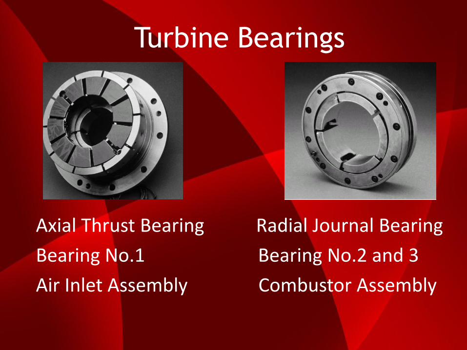
Turbine Bearings
Axial Thrust Bearing Radial Journal Bearing
Bearing No.1 Bearing No.2 and 3
Air Inlet Assembly Combustor Assembly
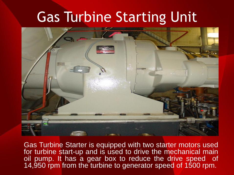
Gas Turbine Starting Unit
Gas Turbine Starter is equipped with two starter motors used for turbine start-up and is used to drive the mechanical main oil pump. It has a gear box to reduce the drive speed of 14,950 rpm from the turbine to generator speed of 1500 rpm.
Gas Turbine Starting Unit
The Gas Turbine Unit has the main function the following:
1.) To put the turbine in rotation to reach ignition speed
(25 % of nominal speed).
2.) When combustion occurs, it supports the acceleration
of the turbine.
3.) When turbine reached 66 % of nominal speed the
starter motor is de-energised. The turbine will be at
self sustaining speed to reach 100% or full speed.

Gas Turbine Starting Unit
Gas Turbine Static Frequency Converter (SFC) uses the synchronous generator of the gas turbine to operate it as a motor to run up to ignition speed and self sustaining speed.

Gas Turbine Generator
Consist of the following components:
1.) Rotor Winding 5.) Output Terminals
2.) Stationary Winding 6.) Bearings
3.) Exciter 7.) Shaft
4.) Diodes

GT Local Control Room
Control, Monitoring and Protections

Central Control Room
Control, Monitoring and Protections

Central Control Room
Typical Central Control Room Operator

Gas Turbine Protections 1.) Pedestal bearing vibrations >Max.
2.) Thrust bearing vibrations >Max.
3.) Turbine casing vibration >Max.
4.) Electronic over speed >110%
5.) Mechanical over speed >112%
6.) Turbine Inlet Temperature (TIT)
7.) Temperature After Turbine (TAT)
8.) Lube pressure and level <Min.
9.) Reverse power relay
10.) Over/under voltage
11.) Over/under frequency
12.) Differential relays

Gas Turbine Operation

HEAT RECOVERY
STEAM GENERATOR
(BOILER)
What is an HRSG?
A heat recovery steam generator or HRSG is an energy recovery heat exchanger that recovers heat from a hot gas stream normally from a Gas Turbine exhaust. It produces LP pressure steam for heating up other auxiliaries and HP superheated steam that can be used in a process to drive a steam turbine in a combined cycle power plant.

Heat Recovery Steam Generator
Consist of the following components:
1.) Diverter Damper 5.) HP Economizer
2.) Super Heater 6.) LP Drum
3.) HP Drum 7.) LP Evaporator
4.) HP Evaporator 8.) Exhaust Stack
HRSG Protections
1.) Diverter Damper Hydraulic Press. < Min.
2.) Flue Gas Temperature > Max.
3.) HP/LP Drum Level >Max.
4.) HP/LP Drum Level <Min.
5.) Stack-out Damper Close
6.) Seal Air Pressure <Min.
7.) HP Feed Water Flow <Min.
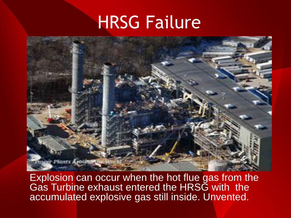
HRSG Failure
Explosion can occur when the hot flue gas from the Gas Turbine exhaust entered the HRSG with the accumulated explosive gas still inside. Unvented.

HRSG Purging
Explosions and fires in a combined cycle (CC) plant may be rare, but when one occurs, it normally results in an extended outage. NFPA 85 for many years has required a fresh air purge of the Combustion Turbine (CT), HRSG, and other CT exhaust systems (for example, by bypass stack) prior to CT startup and operation. The purge rate is a mass flow requirement to provide the required air velocity to ensure dilution and removal of combustible gases prior to light-off of the CT. This purge is specified to be at least five volume changes and no less than 5 minutes in duration. Typical purge times range from 5 to 18 minutes, depending upon the fuel selected, HRSG and duct design, and guidance from the original equipment manufacturer (OEM). The purge cannot be less than 8% of the full power mass flow of the CT.
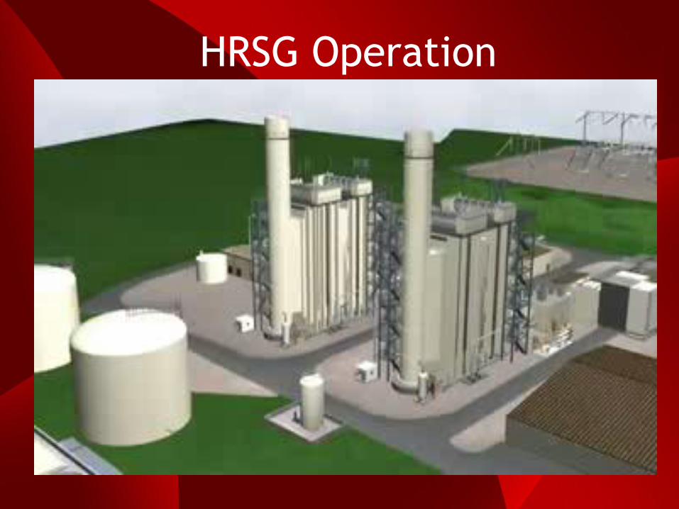
HRSG Operation
STEAM TURBINE

What is an Steam Turbine?
A steam turbine is an industrial device that extracts the thermal energy from the pressurized steam and uses it to do mechanical work on a rotating output shaft. The steam turbine shaft is directly coupled to a generator to convert the mechanical energy into useful power output.
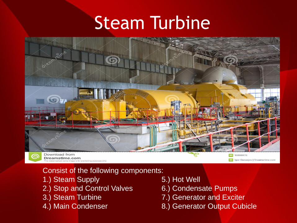
Steam Turbine
Consist of the following components:
1.) Steam Supply 5.) Hot Well
2.) Stop and Control Valves 6.) Condensate Pumps
3.) Steam Turbine 7.) Generator and Exciter
4.) Main Condenser 8.) Generator Output Cubicle
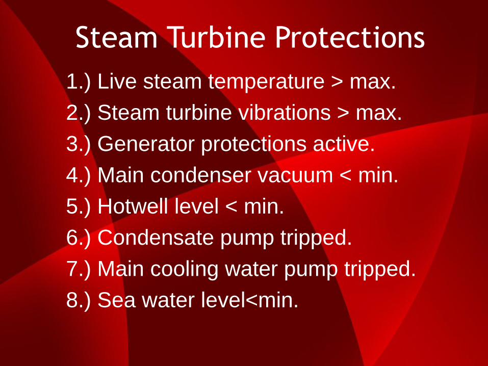
Steam Turbine Protections
1.) Live steam temperature > max.
2.) Steam turbine vibrations > max.
3.) Generator protections active.
4.) Main condenser vacuum < min.
5.) Hotwell level < min.
6.) Condensate pump tripped.
7.) Main cooling water pump tripped.
8.) Sea water level<min.

Steam Turbine Damaged
Admission of wet steam in the Steam Turbine can have water carry-over in the steam supply which can damage the steam turbine blades.

Superheated Steam Flow

STEAM WATER CYCLE
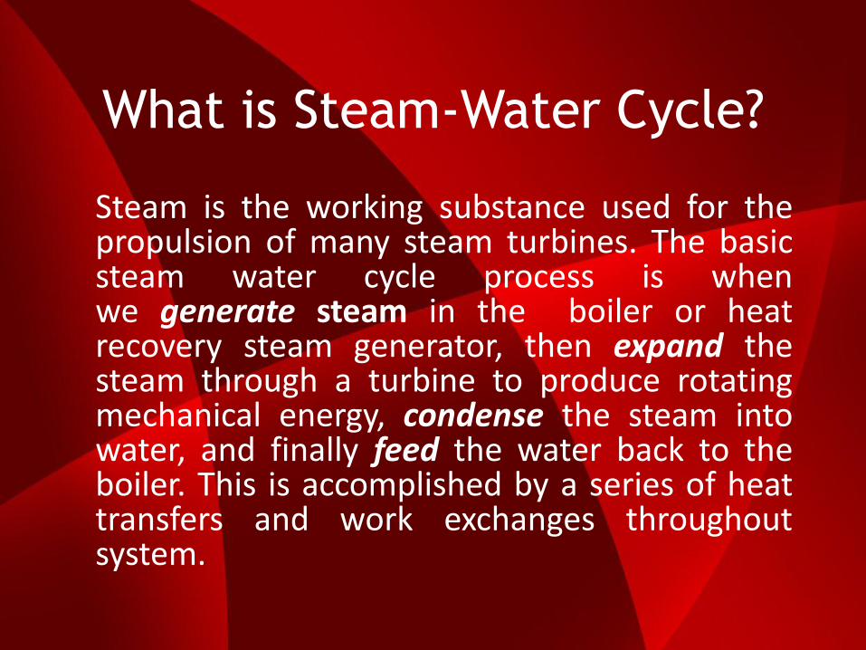
What is Steam-Water Cycle?
Steam is the working substance used for the propulsion of many steam turbines. The basic steam water cycle process is when we generate steam in the boiler or heat recovery steam generator, then expand the steam through a turbine to produce rotating mechanical energy, condense the steam into water, and finally feed the water back to the boiler. This is accomplished by a series of heat transfers and work exchanges throughout system.

Steam Water Cycle

Saturated and Superheated
In a boiler, energy from the fuel is transferred to liquid water in order to create steam. Once the water is heated to boiling point, it is vaporized and turned into saturated steam. When saturated steam is heated above boiling point, dry steam is created and all traces of moisture are erased. This is called super heated steam. Superheated steam has a lower density, so lowering the temperature does not revert it back to its original liquid state. Dropping the temperature of saturated steam, however, will revert it back to its old form of water droplets. Superheated steam has more energy and can work harder than saturated steam, but the heat content is much less useful. This is because superheated steam has the same heat transfer coefficient of air, making it an insulator and poor conductor of heat. Saturated steam is preferred for heating applications, while superheated steam is used mostly in power generation and turbines. If steam is needed for both power generation and heating, the steam can be superheated then desuperheated to its saturated condition.
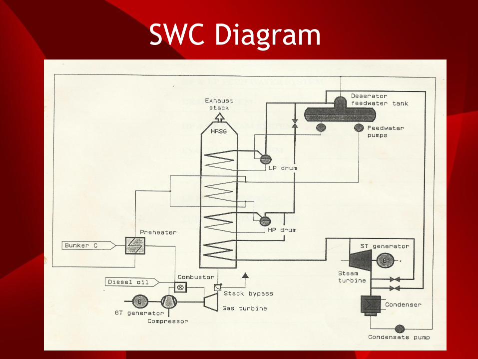
SWC Diagram
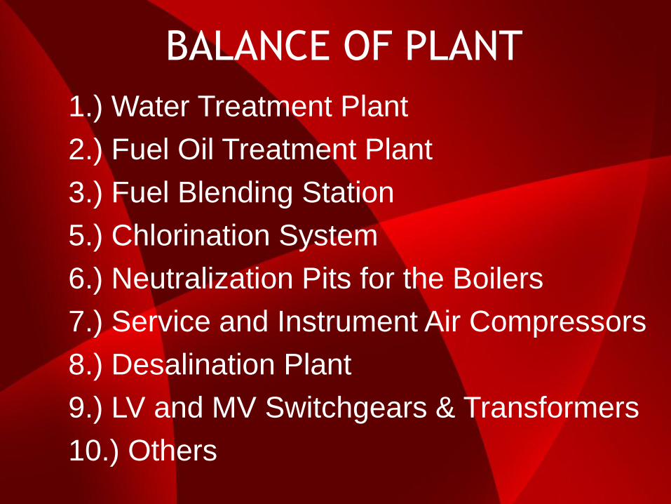
BALANCE OF PLANT
1.) Water Treatment Plant
2.) Fuel Oil Treatment Plant
3.) Fuel Blending Station
5.) Chlorination System
6.) Neutralization Pits for the Boilers
7.) Service and Instrument Air Compressors
8.) Desalination Plant
9.) LV and MV Switchgears & Transformers
10.) Others

Thank You
and
Welcome to IIEE