multifunctional composite sandwich...
TRANSCRIPT

THE 19TH INTERNATIONAL CONFERENCE ON COMPOSITE MATERIALS
1 Introduction Honeycomb sandwich structures are found in a wide variety of applications due to excellent flexural strength-to-weight ratios. Despite this structural advantage, honeycomb sandwich composites typically contain a large encapsulated volume that cannot be accessed after manufacturing. In civilian and defense transportation applications, mass is of significant concern and would benefit from a reduction of parasitic weight associated with fluid storage. Sandwich composites with skins containing embedded microvascular pathways would provide an access route to core compartments for the transport and storage of fluids, which might then be used for functions beyond its primary structural purpose.
2 Background
Nature provides biological inspiration for approaches to meet a wide range of functional needs within structures. Natural composites such as wood [1] or bone [2] serve important structural functions, yet also contain vascular features to enable common biological functions. Microvascular-based functions shared by numerous plants and animals include fluid and nutrient transport, heat dissipation, and waste removal [3,4]. Furthermore these networks are frequently attached to storage volumes contained within the overall structure for purposes of long-term liquid storage and retrieval [5,6]. Recent efforts to mimic these enabling architectures have been successful in embedding vascular pathways within synthetic materials and have demonstrated fluid and heat transfer [7], as well as self-healing abilities [8,9]. However, mimicry of integrated storage volumes has not been
demonstrated for these thermal and healing applications. These capabilities were initially demonstrated within neat polymer matrices and only recently have been realized within fiber-reinforced polymer composites via sacrificial fiber techniques. Despite the advance associated with this state-of-the-art method, the approach would benefit from increased reliability and a route suitable for scalable fiber processing within an industrial production context. 2.1 Current Methods of Microchannels Production
2.1.1 Planar manufacturing methods
Current methods of producing microvascular networks include both planar and 3-D manufacturing techniques. The most commonly utilized technique is soft lithography. This planar technique utilizes a “master” silicon wafer substrate that is patterned with a photoresist layer. The pattern is reproduced within an elastomeric compound, typically polydimethylsiloxane (PDMS) [10]. After curing, the molded elastomer is removed and the patterned face bonded to a secondary panel or additional molded pieces [10,11]. The encapsulated gaps produced by the patterned surface topography create continuous microchannels through which microfluidic flow is possible. The soft lithography method has proven to provide high fidelity and versatility of the patterns at relatively low cost. Although soft lithography is a planar method, laminations of multiple layers can be constructed to form 2.5-D or quasi 3-D structures. Additional planar methods for microvascular network fabrication include subtractive techniques, such as etching and machining. Common etching
MULTIFUNCTIONAL COMPOSITE SANDWICH STRUCTURES UTILIZING EMBEDDED MICROVASCULAR
NETWORKS
J. Tye1, C. Hansen1* 1 Mechanical Engineering, University of Massachusetts, Lowell, USA
* Corresponding author ([email protected])
Keywords: Multifunctional, Sandwich Composites, Honeycomb, Microvascular, Fluid Storage

processes are chemical- or laser-etching methods. Chemical etching involves patterning a photoresist on a substrate that is subsequently removed through a chemical reaction [12]. Laser etching is a subtractive method that ablates selected areas of a surface with a focused laser beam, which controls the channel dimensions by the laser pulse duration and intensity [13,14]. Etched structures are adhered to plates or other patterned samples similar to the soft lithography process. Machining is similar to etching, in that material is removed via micro-scale tooling and Computer Numerically Controlled (CNC) milling. Although low cost, ease of use, and broad material selection have advanced the widespread use of machining, it is not well suited for use on fiber reinforced polymer composites. Fibrous composites can be easily damaged or weakened during machining and the tooling experiences a high wear rate. Similar to the other planar manufacturing methods, 2.5 dimensional networks are possible via lamination processes.
2.1.2 Additive manufacturing
The second general category of microchannel production techniques is additive non-planar methods. Additive manufacturing processes, such as stereolithography, fabricates parts directly from digital models. The models are sliced into planar cross sections of finite thickness. Specific to stereolithography, the computer controls a collimated light beam to polymerize the surface of a photosensitive resin in corresponding planar patterns [15]. This method can yield features on the micron scale but must self-supporting [16] and the materials are limited. Other techniques, such as fused deposition modeling (FDM), can also be used to pattern microchannels.
2.1.3 Sacrificial methods
Recently, the most widely utilized 3-D structure fabrication methods utilize sacrificial or fugitive materials. These methods are increasingly popular due to the expanding range of available materials and processes. The sacrificial approaches broadly fall into categories of controlled or random network distribution. One widely used example of controlled deposition is known as direct ink writing. In this process, viscoelastic fugitive inks are extruded on a
3-axis computer-controlled stage to pattern a 2-D or 3-D structure that is self-supporting. This structure is then infiltrated by a polymer matrix, such as a multi-part reactive or photosensitive resin. Subsequent to matrix polymerization, the viscoelastic ink structure is removed via either a phase change or chemical dissolution process [17,18]. The resultant matrix possesses an embedded microchannel structure in place of the previously solid ink structure. The method is finely controlled and produces channel features from 10 µm to greater than 1 mm in diameter. The wax structure, however, is fragile and susceptible to damage, and is not easily integrated into fiber-reinforced composite materials. A fugitive method with randomly patterned features consists of melt spinning fine fibers of fugitive materials. In a typical example, sugars are melt spun to form a cotton candy like web of fibers varying in size from 1 to 100 µm. The fiber network is infiltrated by polymer resin, which cures and is removed through dissolution within a water and ethanol bath [19]. This rapid method produces a densely packed and highly interconnected network of fibers with randomly varying fiber positions and diameters. Matrix materials are limited to low viscosity formulations, as highly viscous resin systems do not easily infiltrate the network. Additional microchannel fabrication methods include fugitive electrospinning [20] and rapid electrostatic discharge [21], which likewise are not easily incorporated into a fiber-reinforced composite. Recently, the methods detailed above have been evolved by Moore et al. [22], who pioneered a process to manufacture GFRP (glass fiber reinforced polymer) composites with embedded microchannels via a sacrificial fiber processing route. The sacrificial fiber is a commercial PLA (poly lactide) fiber that is chemically treated to incorporate a catalyst to reduce the temperature of fiber depolymerization. Previous studies demonstrated thermal decomposition of neat PLA at temperatures near 280°C [23]. The addition of metallic catalysts reduce the thermal degradation temperature by up to 90°C [24] with blending of calcium oxide or tin-based reagents. Moore et al. determined that the inclusion of tin (II) oxalate within the PLA matrix reduces the degradation temperature to 200°C. The

catalyst was incorporated into the polymer fiber via solvent-induced swelling of the fiber matrix. The fiber is submerged within a solution of water and trifluoroethanol containing suspended tin (II) oxalate catalyst particles. The catalyst diffuses into the fiber core and becomes trapped within the matrix during subsequent solvent evaporation. This process is schematically shown in Figure. 3.
Figure 1. Chemical treatment of PLA fiber to incorporate tin (II) oxalate within the fiber matrix.
After treatment, the sacrificial fibers are woven into glass fiber textiles and cured in a layup infiltrated with epoxy. Once cured, the specimens are heated to 200°C for extended periods of time (24 to 48 hours) to evacuate the sacrificial fibers.
2.2 Microfluidics Fluidic flow through microvascular composites is governed by the flow equations applied to the field of microfluidics. Microfluidic devices have channels with a characteristic length scale that is sub-millimeter in size [25]. These devices have enjoyed widespread use due to primary benefits of achieving laminar flow conditions and use of small volumes of fluid analytes. The Reynolds number, which is a dimensionless ratio of inertial to viscous forces, is directly related to the channel width and thus becomes substantially reduced for fluidic devices with microscale features. At these low Reynolds numbers, the inertial forces are less dominant and steady laminar flow is achieved. The fluid flow flow is described using the Navier-Stokes equation, provided in Equation 1. 𝜌𝜌 = −∇𝑃𝑃 + 𝜌𝜌𝜌𝜌 + 𝜇𝜇∇ 𝑈𝑈 (1) The equation relates relates fluid density ρ, fluid velocity U, applied pressure P, gravitational acceleration g, and the fluid dynamic viscosity µ.
An important concern when using micro-scale channels is the pressure drop required to overcome viscous dissipation forces during fluid transport through the channel. The Hagen-Poiseuille relationship for a circular cross-section tube, provided in Equation 2, relates volumetric flow rate and pressure drop.
𝑄𝑄 = ∆ (2) where Q denotes volumetric flow rate, R is the radius of the circular cross section, ΔP is pressure drop, µ is fluid viscosity, and L is length of the transport path through the channel. While the pressure drop is directly proportional to the length L, it is inversely proportional to the radius to the fourth power. This dramatic increase in the pressure drop as diameter of channel shrinks leads to practical limitations to the channel diameter, particularly for materials systems subject to pressure limitations. 2.3 Sandwich Composites Sandwich composites are utilized in engineering structures for their outstanding flexural properties coupled with low density. A sandwich composite is formed by bonding a face sheet, or skin, to a core. This sandwich is analogous to an I-beam, in which the flexural stiffness is increased by apportioning larger quantities of mass at distances further from the neutral axis to increase the area moment of inertia. The area moment of inertia is inversely related to bending stress, as seen in Equation 3. 𝜎𝜎 = (3) Here, σ is the extensional bending stress, M is the loading moment, y is the distance from the neutral axis to the point of interest, and I is the moment of inertia. The maximum stress occurs at the surface of the skin and varies linearly to the neutral axis, where the stress is equal to zero. The skin must be able to resist the maximum tensile and compressive stresses, while the core materials are substantially less stressed and are typically chosen to add minimal system mass.

3 Experimental 3.1 Sacrificial Fibers
3.1.1 Chemical Incorporation of Catalyst
The first attempt to create sacrificial fiber utilizes the method described within Dong et al. Commercially available fiber was donated from Nextrusion GmbH (Bobingen, Germany). The suspension to swell the fiber contained deionized water, Disperbyk 187 (Byk), trifluoroethanol (TFE) (Sigma-Aldrich), and powdered tin (II) oxalate (Sigma Aldrich). The fiber was coiled around a custom-designed spindle and submerged into the solution for a 24 hour period. After immersion, the spindle and fiber were placed into a drying oven at 45°C overnight to evaporate the solvent. Samples of the treated fiber were then thermally degraded by heating to 200°C while under 101.5 kPa vacuum. Samples ranging from 1 to 5 grams were placed in aluminum weighing dishes and placed into a heated vacuum oven to determine the mass loss under isothermal conditions.
3.1.2 Extrusion of Catalysed Fibers
Due to the sub-optimal results associated with the chemically treated fibers, as discussed in section 4, an extrusion-based sacrificial fiber methodology was developed. PLA resin pellets (2003D, NatureWorks, LLC, Blair, NE) were dried for 2 hours at 90°C as recommended by the manufacturer. The resin pellets were then coated with 1 wt% mineral oil to function as a binder for the 3 wt% tin (II) oxalate and 0.05 wt% added to the pellets. Rhodamine 6G was used as a dye in order to incorporate a florescent ability into the fiber for optical visibility. The pellets were thoroughly coated with the powder by mechanical agitation prior to being fed into the hopper of a single screw extruder. The PLA was extruded through a custom die and pulled through a cooling bath to generate fibers with diameters ranging from 125 to 300 µm. These fibers were then tested identically to the chemically treated fibers to determine mass loss. 3.2 Sandwich Structure Containing Embedded Microvascular Networks
3.2.1 Materials
Sandwich composite specimens are fabricated from a phenolic resin-infused aramid honeycomb core with a 4.7 mm thickness and a cell diameter of 4.76 mm (NH-12B, ACP Composites). The skin is a 4-harness satin weave E-glass fiberglass fabric (120 E-Glass, Fibre Glast) and the resin is a high temperature epoxy with a 200°C continuous operation temperature quoted by the manufacturer (EHT-01, ACP Composites). A polyester scrim layer (Pellon 807 Wonder Web) is added between the skin and the core to prevent excessive resin infiltration into the honeycomb cells and to affix the dry fabric to the core prior to the addition of the resin.
3.2.2 Incorporating Woven PLA Network
Various weaving patterns for the sacrificial fiber networks can be used to dictate the patterning and position of the ultimate microvascular network. Figure 2 schematically presents a ‘through weave’, which undulates between the top and bottom skins, and a ‘one-sided weave’, which remains within a single skin. The different weave patterns strongly influence the fluid flow patterns within the structure (see Results section).
Figure 2. Sacrificial fiber weave patterns include (a) a through weave and (b) a top weave.
3.2.3 Manufacturing
After the sacrificial fibers are patterned within the sandwich skins, the skins are co-cured to the honeycomb core in a single manufacturing step. The PLA fibers remain within the sandwich during the epoxy matrix cure cycle. After curing, the ends of the sacrificial fibers are exposed by polishing or cutting the specimens. Once exposed to the sandwich panel exterior environment, the panel is post-cured at 200°C to evacuate the fibers.
4 Results
4.1 PLA Fiber Manufacturing
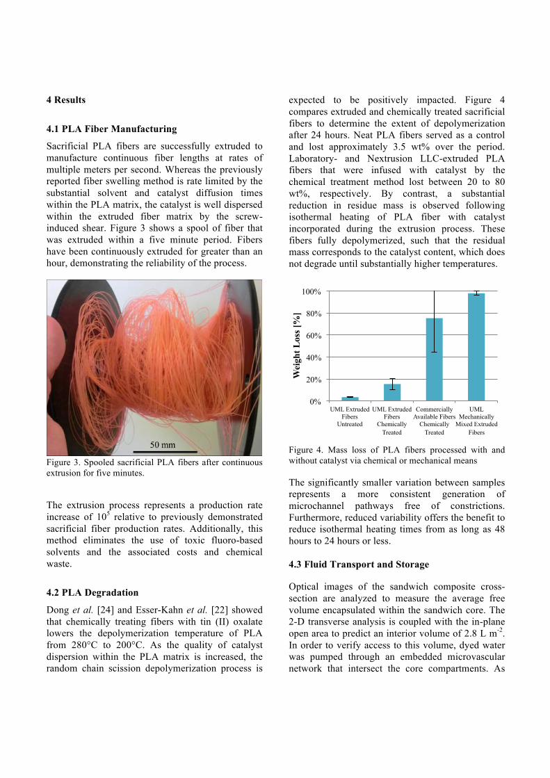
Sacrificial PLA fibers are successfully extruded to manufacture continuous fiber lengths at rates of multiple meters per second. Whereas the previously reported fiber swelling method is rate limited by the substantial solvent and catalyst diffusion times within the PLA matrix, the catalyst is well dispersed within the extruded fiber matrix by the screw-induced shear. Figure 3 shows a spool of fiber that was extruded within a five minute period. Fibers have been continuously extruded for greater than an hour, demonstrating the reliability of the process.
Figure 3. Spooled sacrificial PLA fibers after continuous extrusion for five minutes.
The extrusion process represents a production rate increase of 105 relative to previously demonstrated sacrificial fiber production rates. Additionally, this method eliminates the use of toxic fluoro-based solvents and the associated costs and chemical waste.
4.2 PLA Degradation
Dong et al. [24] and Esser-Kahn et al. [22] showed that chemically treating fibers with tin (II) oxalate lowers the depolymerization temperature of PLA from 280°C to 200°C. As the quality of catalyst dispersion within the PLA matrix is increased, the random chain scission depolymerization process is
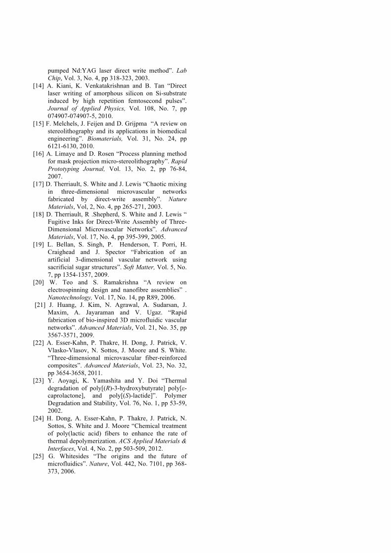
expected to be positively impacted. Figure 4 compares extruded and chemically treated sacrificial fibers to determine the extent of depolymerization after 24 hours. Neat PLA fibers served as a control and lost approximately 3.5 wt% over the period. Laboratory- and Nextrusion LLC-extruded PLA fibers that were infused with catalyst by the chemical treatment method lost between 20 to 80 wt%, respectively. By contrast, a substantial reduction in residue mass is observed following isothermal heating of PLA fiber with catalyst incorporated during the extrusion process. These fibers fully depolymerized, such that the residual mass corresponds to the catalyst content, which does not degrade until substantially higher temperatures.
Figure 4. Mass loss of PLA fibers processed with and without catalyst via chemical or mechanical means The significantly smaller variation between samples represents a more consistent generation of microchannel pathways free of constrictions. Furthermore, reduced variability offers the benefit to reduce isothermal heating times from as long as 48 hours to 24 hours or less. 4.3 Fluid Transport and Storage Optical images of the sandwich composite cross-section are analyzed to measure the average free volume encapsulated within the sandwich core. The 2-D transverse analysis is coupled with the in-plane open area to predict an interior volume of 2.8 L m-2. In order to verify access to this volume, dyed water was pumped through an embedded microvascular network that intersect the core compartments. As
0%
20%
40%
60%
80%
100%
UML Extruded Fibers
Untreated
UML Extruded Fibers
Chemically Treated
Commercially Available Fibers
Chemically Treated
UML Mechanically
Mixed Extruded Fibers
Wei
ght L
oss [
%]

shown in Figure 5, the water successively flows through a row of neighboring cells via a 125 µm diameter channel woven into the top skin of the sandwich. The water infiltration rate is 0.4 mL min-1.
Figure 5. Honeycomb cells are filled, from left to right, with dyed water. Similarly, fluid was removed from the cells via the same microvascular network by pumping air through the channels. Shown in Figure 6, a 0.4 mL min1 air flow rate displaces the water to enable recovery of the dyed water at the right edge of the sample. The reader should note that Figure 6 demonstrates a bottom weave specimen below the honeycomb cells.
Figure 6. Honeycomb cells filled with water are emptied from left to right via air displacement.
Entrapped air is readily visible within Figures 5, indicating that a fraction of the encapsulated volume is not efficiently used for fluid storage. Similarly, Figure 6 retains some dyed fluid after the fluid recovery process. The efficiency of the fluid infiltration and exfiltration processes is extremely sensitive to two main factors: the weave pattern and panel orientation. These two elements independently lead to drastic differences in fluid volume infiltration and recovery fractions. The filling efficiency varies from near 25% to over 90% as the panel orientation varies from 180° to 0° with respect to level for the top weave pattern (i.e., the microchannels in the top skin). The emptying efficiency varies from below 50% for a top weave pattern to over 90% with a bottom weave pattern. A systematic study of the panel orientation effects at various angles about the x-axis and y-axis will be presented in future publications. The fluid transfer rates are also dependent on burst pressure of the cell walls. In the event that the burst pressure is reached, an audible pop is heard. 4.2 Mechanical Testing
Four-point flexural tests were performed on sandwich specimens to determine the impact of embedded microchannels and stored fluids on the panel stiffness. The experimental setup (Figure 7) has a 10 cm support span and a 5 cm loading span.
Figure 7. Experimental four-point bending test setup modified from ASTM D7249.

A typical load-displacement curve resulting from the four-point bending test of a top weave sandwich structures is presented in Figure 8.
Figure 8. Load-displacement curve representative of sandwich composite in four-point flexure.
Mechanical testing indicates that there are no significant differences in flexural modulus or ultimate flexural strength between samples with and without the microchannels. However, storage of water within the core caused material softening and requires further investigation.
5 Conclusions and Future Directions
Microvascular networks are successfully embedded within fiber reinforced polymer composite sandwich structures through the use of sacrificial fiber techniques. Preliminary investigations of extrusion of a PLA fiber with catalyst indicate that the sacrificial depolymerization is improved in terms of cost, rate of manufacture, and rate and thoroughness of depolymerization relative to a chemical treatment technique. Fluid flow through the embedded microchannel networks and into the encapsulated volume of the honeycomb core of the sandwich demonstrates an efficient route for structural storage within composites. The embedded microchannels do not show a statistically significant effect on the sandwich structure mechanical properties.
A primary remaining concern requiring research centers on the manufacture of sacrificial fibers from alternate polymeric systems that possess lower decomposition temperatures. Such systems will enable the sacrificial fiber technique to be used with a broader range of matrix materials. These results will be featured in an upcoming publication.
References [1] K. Chawla “Composite Materials Science and
Engineering”. Springer, 2012. [2] M. Oyen, V. Ferguson “Bone as a Composite
Material. Anonymous Biomechanics of Hard Tissues”. Wiley-VCH Verlag GmbH & Co. KGaA, 2010.
[3] K. McCulloh, J. Sperry and F. Adler. “Water transport in plants obeys Murray's law”. Nature, Vol. 421, No. 6926, pp 939-942, 2003.
[4] H. Stone and S. Kim “Microfluidics: Basic issues, applications, and challenges”. AIChE Journal, Vol. 47, No. 6, pp 1250-1254, 2001.
[5] K. Nagy “Seasonal patterns of water and energy balance in desert vertebrates”. Journal of Arid Environments, Vol. 14, pp 201-210, 1998.
[6] B.Gartner “Plant Stems: Physiology and Morphology”. Academic Press, Inc., 1995.
[7] B. Kozola, L. Shipton, V. Natrajan, K. Christensen and S. White “Characterization of Active Cooling and Flow Distribution in Microvascular Polymers”. Journal of Intelligent Material Systems and Structures, Vol. 21, No. 12, pp 1147-1156, 2010.
[8] K. Toohey, C. Hansen, J. Lewis, S. White and N. Sottos “Delivery of Two-Part Self-Healing Chemistry via Microvascular Networks”. Advanced Functional Materials, Vol. 19, No. 9, pp 1399-1405, 2009.
[9] R. Trask, H. Williams and I. Bond. “Self-healing polymer composites: mimicking nature to enhance performance”. Bioinspiration & Biomimetics, Vol. 2, No. 1, pp 1, 2007.
[10] Y. Xia and G. Whitesides “Soft Lithography”. Annual Review of Material Science, Vol. 28, pp 153-184, 1998.
[11] H. Wu, B. Huang and R. Zare “Construction of microfluidic chips using polydimethylsiloxane for adhesive bonding”. Lab on a Chip, Vol. 5, No. 12, pp 1393-1398.
[12] G. Kovacs, K. Petersen and M. Albin “Silicon Micromachining: Sensors to Systems”. Anal Chem, Vol. 68, No. 13, pp407A-412A, 1998.
[13] D. Lim, Y. Kamotani, B. Cho, J. Mazumder and S. Takayama “Fabrication of microfluidic mixers and artificial vasculatures using a high-brightness diode-
0
2
4
6
8
10
12
0 0.001 0.002 0.003 0.004
Loa
d (N
)
Displacement (m)
pumped Nd:YAG laser direct write method”. Lab Chip, Vol. 3, No. 4, pp 318-323, 2003.
[14] A. Kiani, K. Venkatakrishnan and B. Tan “Direct laser writing of amorphous silicon on Si-substrate induced by high repetition femtosecond pulses”. Journal of Applied Physics, Vol. 108, No. 7, pp 074907-074907-5, 2010.
[15] F. Melchels, J. Feijen and D. Grijpma “A review on stereolithography and its applications in biomedical engineering”. Biomaterials, Vol. 31, No. 24, pp 6121-6130, 2010.
[16] A. Limaye and D. Rosen “Process planning method for mask projection micro-stereolithography”. Rapid Prototyping Journal, Vol. 13, No. 2, pp 76-84, 2007.
[17] D. Therriault, S. White and J. Lewis “Chaotic mixing in three-dimensional microvascular networks fabricated by direct-write assembly”. Nature Materials, Vol, 2, No. 4, pp 265-271, 2003.
[18] D. Therriault, R .Shepherd, S. White and J. Lewis “ Fugitive Inks for Direct-Write Assembly of Three-Dimensional Microvascular Networks”. Advanced Materials, Vol. 17, No. 4, pp 395-399, 2005.
[19] L. Bellan, S. Singh, P. Henderson, T. Porri, H. Craighead and J. Spector “Fabrication of an artificial 3-dimensional vascular network using sacrificial sugar structures”. Soft Matter, Vol. 5, No. 7, pp 1354-1357, 2009.
[20] W. Teo and S. Ramakrishna “A review on electrospinning design and nanofibre assemblies” . Nanotechnology, Vol. 17, No. 14, pp R89, 2006.
[21] J. Huang, J. Kim, N. Agrawal, A. Sudarsan, J. Maxim, A. Jayaraman and V. Ugaz. “Rapid fabrication of bio-inspired 3D microfluidic vascular networks”. Advanced Materials, Vol. 21, No. 35, pp 3567-3571, 2009.
[22] A. Esser-Kahn, P. Thakre, H. Dong, J. Patrick, V. Vlasko-Vlasov, N. Sottos, J. Moore and S. White. “Three-dimensional microvascular fiber-reinforced composites”. Advanced Materials, Vol. 23, No. 32, pp 3654-3658, 2011.
[23] Y. Aoyagi, K. Yamashita and Y. Doi “Thermal degradation of poly[(R)-3-hydroxybutyrate] poly[ε-caprolactone], and poly[(S)-lactide]”. Polymer Degradation and Stability, Vol. 76, No. 1, pp 53-59, 2002.
[24] H. Dong, A. Esser-Kahn, P. Thakre, J. Patrick, N. Sottos, S. White and J. Moore “Chemical treatment of poly(lactic acid) fibers to enhance the rate of thermal depolymerization. ACS Applied Materials & Interfaces, Vol. 4, No. 2, pp 503-509, 2012.
[25] G. Whitesides “The origins and the future of microfluidics”. Nature, Vol. 442, No. 7101, pp 368-373, 2006.