mechanical behaviour of 3d woven...
TRANSCRIPT

THE 19TH INTERNATIONAL CONFERENCE ON COMPOSITE MATERIALS
1 Introduction
Compared to conventional pre-preg tape laminates, 3D woven composites provide higher through-thickness properties, reduced manufacturing costs, and the potential for automated out-of-autoclave manufacture. However, the in-plane mechanical properties of 3D woven composites may not be as desirable due to the tow crimps introduced by the weaving process [1,2]. The failure mechanisms of different types of 3D woven composites under tensile, compression and flexure were studied in [3,4]. However, only limited data on the performance of 3D woven composites under different loading conditions were available. Only few data were published on the flexure strength [5]. The mechanism of compressive failure still needs further investigation [5]. It is clear that more experimental data are needed for further understanding of the mechanical behaviour 3D woven composites. In this paper, six different types of 3D woven carbon fibre reinforced composites were manufactured and tested under tension, compression and flexure. The elastic and strength properties of the all six types of 3D woven composites are presented. The effects of weave architecture on the mechanical behaviour are investigated and discussed in this paper.
2 Materials
The carbon fibre preforms were manufactured using a traditional narrow fabric weaving loom (Muller-NC2-S) by M.Wright & Sons Ltd. Four types of non-crimp orthogonal woven preforms and two types of angle-interlock woven preforms were fabricated. The idealised fibre architectures of the
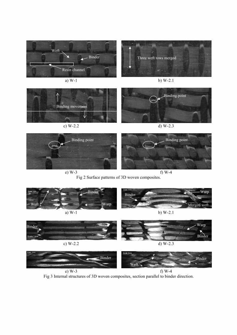
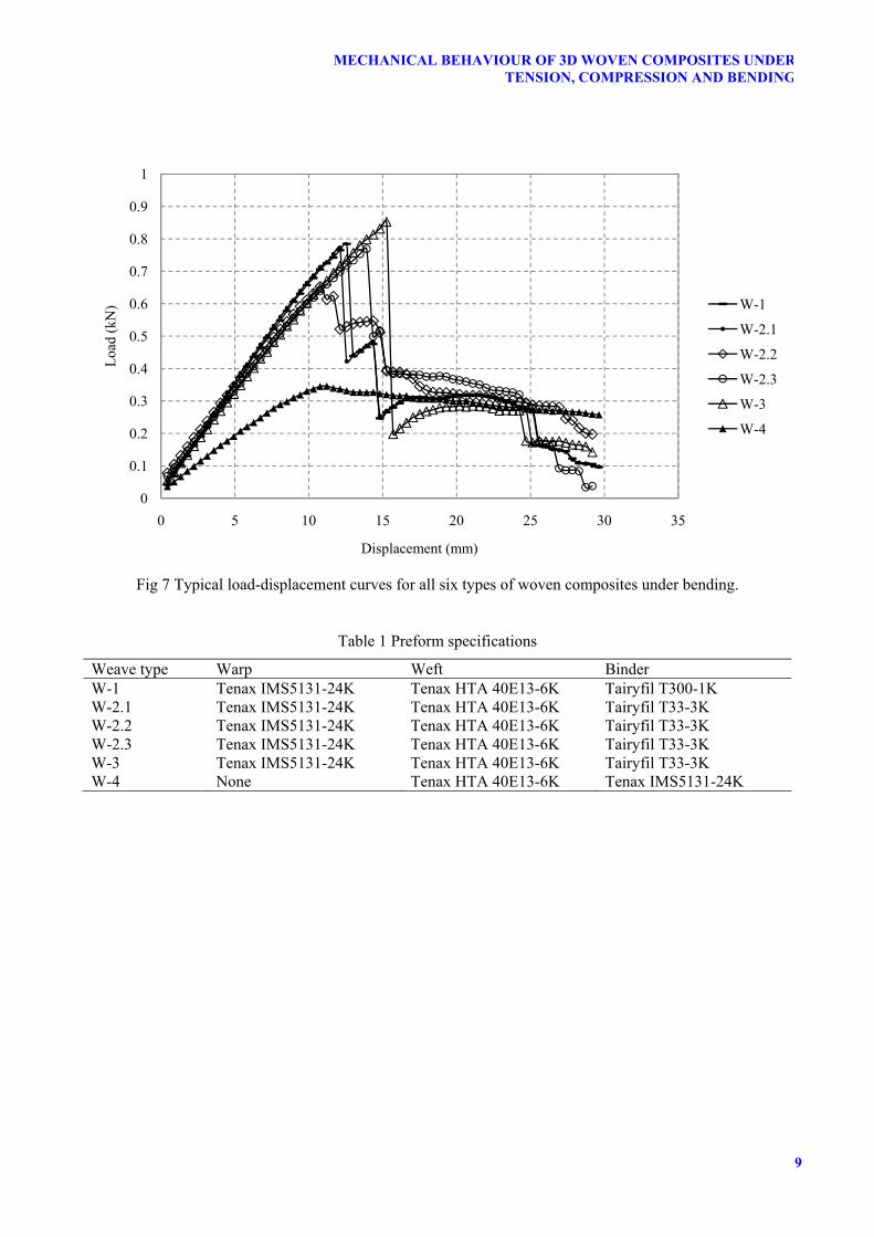
six weaves are illustrated in Fig 1. Table 1 shows the details of fibres used in each weave design. Since the preform was manufactured using a traditional narrow fabric weaving loom, the width of the fabric was limited to 80mm. The fabric was cut into 350mm long strips to fit into the close mould. The preform strips were placed in a closed mould tool for resin transfer moulding (RTM). The nominal thickness of the fabric was 3mm. Prime 20LV and slow hardener were mixed, degased and injected to the vacuumed mould using Hypaject MK-III. The initial injection pressure was 1 bar. Once the resin flowed to the outlet, the outlet was closed off and the injection pressure was then increased to 1.5 bar and kept for 5 minutes. This is to further push the resin into the mould and fill in any possible voids or dry spots on the fabric. The temperature of the mould tool was kept at 30°C to reduce the viscosity of the resin and aid resin impregnation. Once the injection was completed, the mould was heated up to 50°C for curing. The actual fibre architecture of the composites is largely affected by the weaving process. Although the designed tow spacing parameters were the same for all six types of weaves, the actual tow spacing varies from weave to weave due to the tension on the yarns and the interlacing yarn movements during the weaving process. The weft tow position is largely affected by the binding movement. For instance, the three weft tows bound together in W-2.1 merged into one large tow as shown in Fig 2. Also the weft tow path did not stay straight in W-2.2 and W-2.3. Instead, the weft tow deviated from designed straight path at each binding point and moved towards the next binding point on the tow due to the opposite binding
MECHANICAL BEHAVIOUR OF 3D WOVEN COMPOSITES UNDER TENSION, COMPRESSION AND BENDING
S. Dai1*, P.R. Cunningham1, S. Marshall2, C. Silva2
1 Aeronautical and Automotive Engineering Department, Loughborough University, Loughborough, UK
2 M.Wright and Sons Ltd, Quorn Mills, Quorn, Loughborough, UK * Corresponding author ([email protected])
Keywords: textile composites; 3D weave; mechanical properties; carbon fibre composites

movements at adjacent binding points. For W-1, W-3, and W-4, two adjacent binding points on a weft tow have the same binding movement which keeps the weft tows straight. Fig 3 shows the microscopic photos of the internal fibre architectures of the composites. For W-1, W-2.2, W-2.3 and W-3, the warp tows demonstrate relatively high straightness. W-1 shows a great uniformity in the internal architecture. The waviness of the warp tows in W-2.1 is considerably higher than that of the other orthogonal weaves due to the less uniformity of the weft tow structure. The weft tows in W-2.1 are clustered together by the binding process, which leaves a large space between the clustered tows. The free space between clustered weft tows causes the warp tow to deviate from straight path. The fibres within the warp tows deflect and move within the free space which increased the raw warp tow cross-section area within the space and hence increased waviness. The fibre volume fraction of the composites was obtained through matrix burn-off tests. The nominal total fibre volume fraction of all types of woven composites except W-3 is 50% with 28% warp tows, 20% weft tows and 2% binder tows. The angle-interlock weave W-3 has a total fibre volume fraction of 46%, with 26% warp tows, 18% weft tows and 2% binder tows. All samples were tested with the main testing axis parallel to the warp direction. All tests were conducted under displacement control. The modulus and strength of all six types of woven composites under all three loading conditions are summarised in Fig 4.
3 Tensile
Tension tests were conducted according to ASTM D3039. Fig 5 shows the typical stress-strain behaviour of all six types of weaves. All weave types exhibited linear stress-strain behaviour in the initial part of loading. W-4 shows a extent of nonlinearity at the later stage of loading. Unfortunately, the strain gauge failed before the final failure of the specimen and no strain data were recorded near failure. The typical sequence of failure
is: matrix cracking between weft tows, pull out of warp tows, and warp/binder tow rupture. It can be seen from Fig 4. that in both tensile modulus and tensile strength, W-4 is dramatically lower than other weaves since no straight warp tows exist in W-4. The straightness of the warp tows has a strong effect on the tensile modulus. As shown in Fig 3, W-1, W-2.2 and W-3 all have relatively straight warp tows, while the warp tows of both W-2.1 and W-2.3 have certain degree of waviness. Therefore the tensile modulus is higher for W-1, W-2.2, and W-3 than for W-2.1 and W-2.3. The tensile strength, on the other hand, can be affected by the irregularity of the geometry. As mentioned in the previous section, the orthogonal weave W-1 and angle-interlock weave W-3 have the highest structural regularity, which results in higher tensile strength. Due to the vertical insertion of binder tows, all orthogonal weaves have clear resin channels between weft tows as shown in Fig 2. This resin rich region is considered to be the weak zone of the structure. It was observed during testing that the resin around the binder tow at binding point started to crack first. This phenomena was clearly observed in W-2.1 where the resin channels are wider than in other weaves. The matrix cracking is followed by warp tow and matrix debonding. The cracks at the binding points propagated and coalesced in the resin channel. The warp tows are the main load bearing components under tension. The final failure is the warp tow fracture. In all orthogonal samples, the warp tows failed near a resin channel. In some samples of W-1, delamination occurred from the warp tow fracture site. No cracks were observed within the weft tows. Most of the weft tows were broken off from the specimen during loading and did not have fracture across the entire cross-section. In W-1, cracks in the resin channel occurred in pairs on both sides of the sample. In W-3, since the adjacent binding points on a weft tow are further apart than that in the orthogonal weaves, the stress distribution on a weft tow is less uniform. The stress concentration still occurred near the binding points. The straightening of the binders were observed during testing, which resulted in weft tow breakage across the whole cross-section from

3
MECHANICAL BEHAVIOUR OF 3D WOVEN COMPOSITES UNDERTENSION, COMPRESSION AND BENDING
the binding point. Although the resin rich channel is not macroscopically visible in W-3, it was noticed that the crack started from the binding point and propagated between two adjacent weft tows. Cracks along the weft direction were also observed within some weft tows which causes weft tow split. The warp tow fractured at final failure. The angle interlock weave W-4 does not contain straight warp tows. It was observed that the cracks on the surface initiated at every binding point and propagated along the binder. No delamination occurred since there are no distinctive layers in this types of weave. However, some cracks propagated through the thickness along the binders. Since there are no straight warp tows in this weave type, the final failure is the fracture of binder tows. The straightening effect of the binder tows is the account for the non-linear behaviour at the later stage of loading.
4 Compression
Compression tests were carried out following the modified ASTM D695. Modulus and strength were obtained from separate tests of a strain gauged un-tabbed sample and an end-tabbed sample correspondingly. An anti-buckling guide was used on both tests. Acceptable failure occurred within the gauge length of the tabbed specimens. Fig 6 shows the typical load-displacement curves for compression tests on end-tabbed specimens. The compression failure occurred at the resin channel between weft tows. The main failure modes are matrix cracking, warp tow kinking, and delamination for some of the samples. Similar to the tensile properties, W-4 has the lowest compressive modulus and compressive strength due to the absence of straight warp tows. The weaves with more crimped warp tow exhibit lower compressive modulus, such as W-2.1. The angle interlock weave W-3 shows a great potential in both compressive modulus and strength. In W-3, the binder passes through each layer of weft tows, which then prevents the structure from buckling and delays final failure. On the other hand, the binder in the orthogonal weaves only binds the weft tows at the surface of the weave, which may not prevent buckling as effective as in the angle interlock weave.
In W-2.1, W-2.2, and W-2.3, delamination cracks occurred between the first warp layer and the second weft layer. W-2.1 was found to have the longest delamination cracks among all orthogonal weaves. Only limited delamination was observed in W-1. The angle-interlock weave W-3 has longer delamination cracks than all other weaves. Compared to the orthogonal weaves, delamination cracks can propagate longer distance without encountering a binder tow in the through-thickness direction. The relatively longer unit cell is also the account for the longer delamination cracks. In W-4, no delamination was observed since every weft tow and every binder tow are interlaced together. However, cracks were observed to propagate along the binder tow through the thickness and separate the binder tows from the weft tows.
5 Flexure
Three point bending tests were conducted following ASTM D790 using a 40:1 span-to-thickness ratio. The flexure failure combines features of both compression and tension failure. Fig 7 shows typical load and displacement curves for all six types of weaves. It can be seen in Fig 7 that there is no sudden load drop in W-4. The absence of straight warp tows in W-4 causes low flexure strength and modulus. However, no catastrophic failure occurred to W-4 and it can even carry more load than all other weaves at large displacement where other weaves already failed catastrophically. Both W-2.1 and W-3 have higher flexural modulus and strength than other weaves. It is inferred that the lower angle of binder path will increase the stiffness of the structure. Although W-2.1 is orthogonally woven, its binder path has a much lower angler than the other orthogonal weaves, as can be seen from Fig 3. In all the orthogonal weaves, matrix cracking and binder rupture occurred at the binding points in the resin channel on the compression side of the sample. Matrix cracking and warp tow debonding also occurred in the resin channel on the tensile side of the sample. The first layer of warp tows near
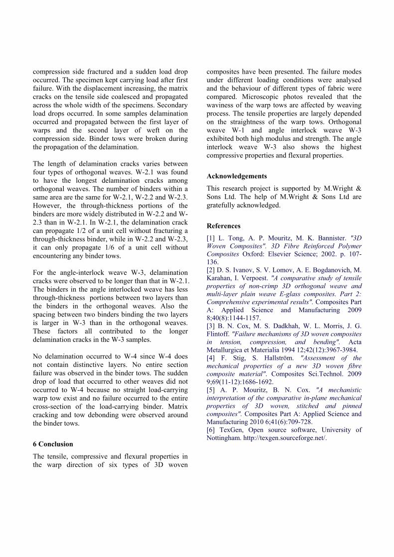
compression side fractured and a sudden load drop occurred. The specimen kept carrying load after first failure. With the displacement increasing, the matrix cracks on the tensile side coalesced and propagated across the whole width of the specimens. Secondary load drops occurred. In some samples delamination occurred and propagated between the first layer of warps and the second layer of weft on the compression side. Binder tows were broken during the propagation of the delamination. The length of delamination cracks varies between four types of orthogonal weaves. W-2.1 was found to have the longest delamination cracks among orthogonal weaves. The number of binders within a same area are the same for W-2.1, W-2.2 and W-2.3. However, the through-thickness portions of the binders are more widely distributed in W-2.2 and W-2.3 than in W-2.1. In W-2.1, the delamination crack can propagate 1/2 of a unit cell without fracturing a through-thickness binder, while in W-2.2 and W-2.3, it can only propagate 1/6 of a unit cell without encountering any binder tows. For the angle-interlock weave W-3, delamination cracks were observed to be longer than that in W-2.1. The binders in the angle interlocked weave has less through-thickness portions between two layers than the binders in the orthogonal weaves. Also the spacing between two binders binding the two layers is larger in W-3 than in the orthogonal weaves. These factors all contributed to the longer delamination cracks in the W-3 samples. No delamination occurred to W-4 since W-4 does not contain distinctive layers. No entire section failure was observed in the binder tows. The sudden drop of load that occurred to other weaves did not occurred to W-4 because no straight load-carrying warp tow exist and no failure occurred to the entire cross-section of the load-carrying binder. Matrix cracking and tow debonding were observed around the binder tows.
6 Conclusion
The tensile, compressive and flexural properties in the warp direction of six types of 3D woven
composites have been presented. The failure modes under different loading conditions were analysed and the behaviour of different types of fabric were compared. Microscopic photos revealed that the waviness of the warp tows are affected by weaving process. The tensile properties are largely depended on the straightness of the warp tows. Orthogonal weave W-1 and angle interlock weave W-3 exhibited both high modulus and strength. The angle interlock weave W-3 also shows the highest compressive properties and flexural properties.
Acknowledgements
This research project is supported by M.Wright & Sons Ltd. The help of M.Wright & Sons Ltd are gratefully acknowledged.
References
[1] L. Tong, A. P. Mouritz, M. K. Bannister. "3D Woven Composites". 3D Fibre Reinforced Polymer Composites Oxford: Elsevier Science; 2002. p. 107-136. [2] D. S. Ivanov, S. V. Lomov, A. E. Bogdanovich, M. Karahan, I. Verpoest. "A comparative study of tensile properties of non-crimp 3D orthogonal weave and multi-layer plain weave E-glass composites. Part 2: Comprehensive experimental results". Composites Part A: Applied Science and Manufacturing 2009 8;40(8):1144-1157. [3] B. N. Cox, M. S. Dadkhah, W. L. Morris, J. G. Flintoff. "Failure mechanisms of 3D woven composites in tension, compression, and bending". Acta Metallurgica et Materialia 1994 12;42(12):3967-3984. [4] F. Stig, S. Hallström. "Assessment of the mechanical properties of a new 3D woven fibre composite material". Composites Sci.Technol. 2009 9;69(11-12):1686-1692. [5] A. P. Mouritz, B. N. Cox. "A mechanistic interpretation of the comparative in-plane mechanical properties of 3D woven, stitched and pinned composites". Composites Part A: Applied Science and Manufacturing 2010 6;41(6):709-728. [6] TexGen, Open source software, University of Nottingham. http://texgen.sourceforge.net/.

5
MECHANICAL BEHAVIOUR OF 3D WOVEN COMPOSITES UNDERTENSION, COMPRESSION AND BENDING
a) W-1 b) W-2.1
c) W-2.2 d) W-2.3
e) W-3 f) W-4
Fig 1 Idealised preform architectures (generated by TexGen [6])
Binder
Weft
Warp
Binder Weft
Weft
Binder
c
c
Fig 3 Intern
Bind
Weft
R
a) W-1
c) W-2.2
e) W-3 Fig 2
a) W-1
c) W-2.2
e) W-3 al structures
ding movemen
Resin channel
Binding p
Surface patt
of 3D wove
nt
Binder
Binder
Wa
Bind
point
terns of 3D w
en composite
arp
der
Bi
woven compo
s, section pa
Three w
Weft
nder
b) W-2.
d) W-2.
f) W-4osites.
b) W-2.
d) W-2.
f) W-4arallel to bind
weft tows merg
Bind
Bin
.1
.3
4
.1
.3
4 der direction
ged
ding point
ding point
Me
.
Binder
Warp
erged weft
Binder
Warp
WW

7
MECHANICAL BEHAVIOUR OF 3D WOVEN COMPOSITES UNDERTENSION, COMPRESSION AND BENDING
a) Tensile behaviour
b) Compressive behaviour
c) Flexural behaviour
Fig 4 Mechanical properties of six types of woven composites.
0
10
20
30
40
50
60
70
80
90
100
Ten
sile
mod
ulus
(G
Pa)
Weave type
W-1
W-2.1
W-2.2
W-2.3
W-3
W-4
0
200
400
600
800
1000
1200
1400
1600
Ten
sile
str
engt
h (M
Pa)
Weave type
W-1
W-2.1
W-2.2
W-2.3
W-3
W-4
0
20
40
60
80
100
120
Com
pres
sive
mod
ulus
(GP
a)
Weave type
W-1
W-2.1
W-2.2
W-2.3
W-3
W-4
0
100
200
300
400
500
600
700C
ompr
essi
ve s
tren
gth
(MP
a)
Weave type
W-1
W-2.1
W-2.2
W-2.3
W-3
W-4
0
10
20
30
40
50
60
70
Fle
xura
l mod
ulus
(G
Pa)
Weave type
W-1
W-2.1
W-2.2
W-2.3
W-3
W-4
0
200
400
600
800
1000
1200
Fle
xura
l str
engt
h (M
Pa)
Weave type
W-1
W-2.1
W-2.2
W-2.3
W-3
W-4
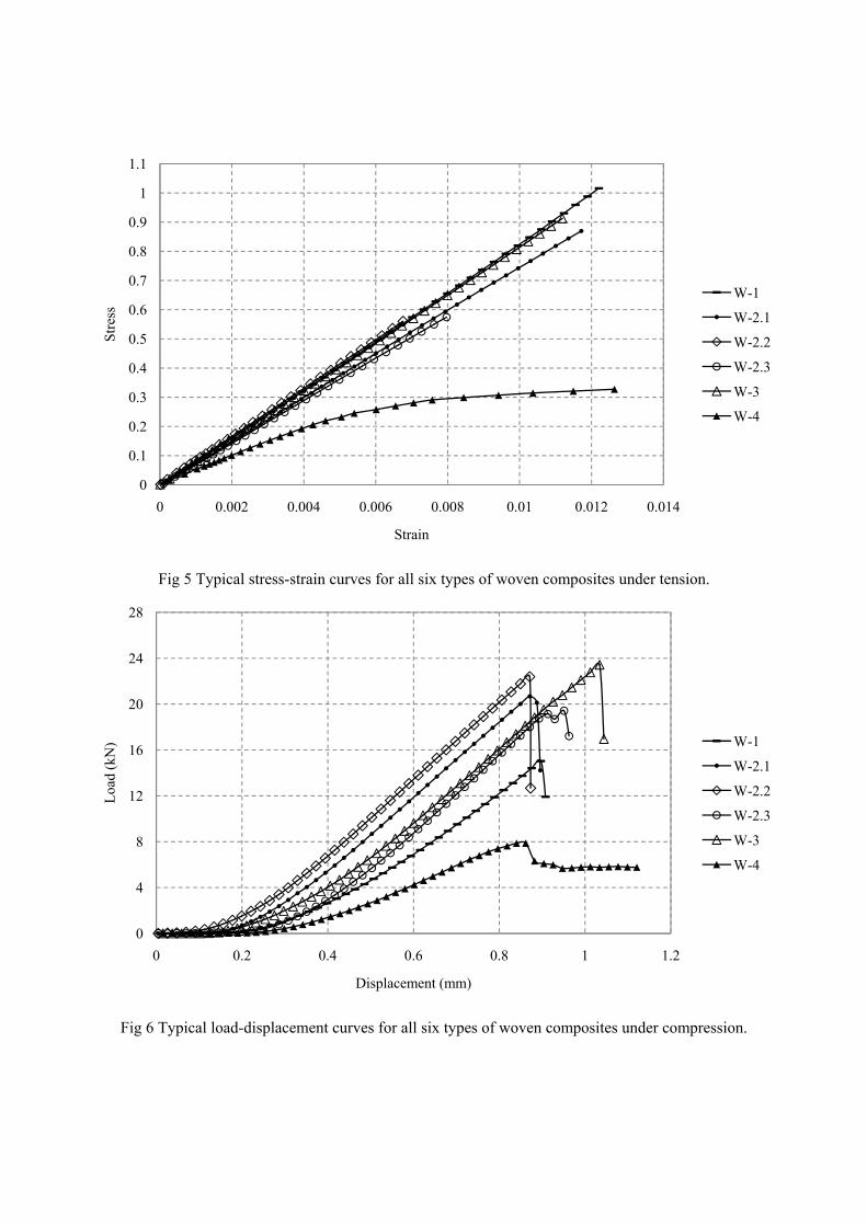
Fig 5 Typical stress-strain curves for all six types of woven composites under tension.
Fig 6 Typical load-displacement curves for all six types of woven composites under compression.
0
0.1
0.2
0.3
0.4
0.5
0.6
0.7
0.8
0.9
1
1.1
0 0.002 0.004 0.006 0.008 0.01 0.012 0.014
Str
ess
Strain
W-1
W-2.1
W-2.2
W-2.3
W-3
W-4
0
4
8
12
16
20
24
28
0 0.2 0.4 0.6 0.8 1 1.2
Loa
d (k
N)
Displacement (mm)
W-1
W-2.1
W-2.2
W-2.3
W-3
W-4
9
MECHANICAL BEHAVIOUR OF 3D WOVEN COMPOSITES UNDERTENSION, COMPRESSION AND BENDING
Fig 7 Typical load-displacement curves for all six types of woven composites under bending.
Table 1 Preform specifications
Weave type Warp Weft Binder W-1 Tenax IMS5131-24K Tenax HTA 40E13-6K Tairyfil T300-1K W-2.1 Tenax IMS5131-24K Tenax HTA 40E13-6K Tairyfil T33-3K W-2.2 Tenax IMS5131-24K Tenax HTA 40E13-6K Tairyfil T33-3K W-2.3 Tenax IMS5131-24K Tenax HTA 40E13-6K Tairyfil T33-3K W-3 Tenax IMS5131-24K Tenax HTA 40E13-6K Tairyfil T33-3K W-4 None Tenax HTA 40E13-6K Tenax IMS5131-24K
0
0.1
0.2
0.3
0.4
0.5
0.6
0.7
0.8
0.9
1
0 5 10 15 20 25 30 35
Loa
d (k
N)
Displacement (mm)
W-1
W-2.1
W-2.2
W-2.3
W-3
W-4