multicriteria design of sailplane airfoils -...
TRANSCRIPT

ISTP-16, 2005, PRAGUE 16TH INTERNATIONAL SYMPOSIUM ON TRANSPORT PHENOMENA
MULTICRITERIA DESIGN OF SAILPLANE AIRFOILS
L. Popelka 1, M. Mat ejka, 2, J. Nozicka 3, V. Uruba 4
Keywords: airfoils, optimization, CFD, wind-tunnel testing, flight evaluation
SummaryThe article presents results of multicrite-ria aerodynamic design of airfoils suited forsailplanes. Airfoils for root and tip wing sec-tion as well as for empennage has been de-signed. Wind tunnel testing has proved thefeasibility of such approach. The use of turbu-lators has been proposed on two older airfoils.
1. IntroductionCross-country flight of a sailplane togetherwith take-off and landing regimes create con-flicting demands on performance. To enhanceairfoil aerodynamic properties, an optimiza-tion task based on target criteria and Xfoilsolver has been created. Since the constraintof trailing edge shape for easy manufacture hasbeen applied, the resulting airfoils are not gen-eral solutions of the task, but an overall im-provement has been gained over the best pub-lished airfoils in selected category.
2. Airfoil tailoringWing airfoils have been designed for a concep-tual study of a club class sailplane, Fig. 1. New
airfoils are labeled as PW212-163 (root) andPW312-163 (tip). 33 target criteria in threeflight regimes have been used, as establishedin previous workPopelka et al (2004). The air-foils for the empennage - PW401-137 K25 forhorizontal stabilizer and PW402-136 for verti-cal stabilizer have been tailored as well. Mod-ifications arose from successful design DU86-137/25, Boermanns & Bennis (1992). Con-tours and calculated aerodynamic coefficientsof PW series airfoils, Figs. 2 to 7.
3. Wind-tunnel testingMajor part of experimental investigation hasbeen carried out in the general purpose closed-circuit 750x550mm wind tunnel CTU. Smokewire visualisation for the same flow conditionsshowed (Fig. 8) that separation bubbles onupper side of PW212-163 airfoil has been re-duced in comparison with reference Wortmannairfoil. Lower side turbulator has become ef-fective at 0.5 x/c, Fig. 9. Separation bub-ble has been eliminated and turbulent bound-ary layer can overcome relatively steep pres-sure rise. PIV measurement has been carried
1Ing. Lukas Popelka: Institute of Thermomechanics AS CR; Dolejskova 5, CZ 182 00 Prague 8; tel.+420 266 053 394, e-mail: [email protected]
2Ing. Milan Matejka: Department of Fluid Dynamics and Thermodynamics, FME, CTU in Prague; Technicka 4,CZ 166 07, Prague 6; tel. +420 224 352 661, e-mail: [email protected]
3Prof. Ing. Jirı Nozicka, CSc.: Department of Fluid Dynamics and Thermodynamics, FME, CTU in Prague;Technicka 4, CZ 166 07, Prague 6; tel. +420 224 352 580, e-mail: [email protected]
4Ing. Vaclav Uruba, CSc.: Institute of Thermomechanics AS CR; Dolejskova 5, CZ 182 00 Prague 8; tel.+420 286 588 547, e-mail: [email protected]
1

out on Wortmann FX66-17AII-182 airfoil inorder to study the separation and stall and forfeasibility studies on flow contol, Fig. 10.
4. In-flight testingInitial in-flight performance measurement hasbeen completed on club class sailplane toprove the possibilities of low-cost GPS sys-tems. Created methodology will be applied forevaluation of profile drag reduction on VSB-62sailplane, as mentioned in following chapter.
5. Modifications of older airfoilsTurbulators can affect significantly the proper-ties of older airfoils. Xfoil solution create aquick and verified tool for such analysis. On-going survey on sailplanes used in Czech Re-public has shown, that a room for improvementcould be found on VSB-62 wing and VSO-10empennage. Forced transition on both sidesof Eppler STF863-615 airfoil used on entireVSB-62 wing yields reduction of detrimentallaminar separation bubbles, Fig. 11 sq. Similarpromising results are predicted on NACA 64-009, NACA 64-0012 which create the empen-nage of VSO-10 sailplane, Fig. 14 sq. Trendsof polar shape are in general agreement withfindings of wind-tunnel testing performed byAlthaus (1991)on Wortmann FX 71-L-150 air-foil. Calculations show a slight increase ofdrag under the conditions without flap deflec-tion. This fact is an inspiration for further ex-perimental work and visualisation could prove,if laminar boundary layer can overcome un-sealed gap and continue on the flap itself.
6. ConclusionsConceptual design of specific sailplane cat-egory with new airfoils is a logical conse-quence of complex project, aiming at synthe-sis of numerical modelling, wind-tunnel andin-flight testing. Created methodology, whichwas herein used for club class can be employed
for arbitrary sailplane. Parallel programme fortraining class has been established in extent ofairfoil selection according to optimization crit-era and conceptual study of entire sailplane.Another more general aim is to study the pos-sibilities of active control of boundary layertransition to replace fixed turbulator strips usednowadays, as initiated bySartorius (2002).
7. AcknowledgmentAuthors would like to express their thanks toall technicians and consultants of the project,namely Mr. Zdenek Kolek and BorivojPenc (CTU in Prague), RNDr. Pavel Jonas,DrSc. (IT AS CR), Jan Rensa, DiS., Ven-dula Rensova, Bc. Karel Benes, Ing. HynekMorkovsky and Ing. Michal Sedlak (AeroclubPolicka).Grant support of GA AS CR No. A2076403 isgratefully acknowledged.
6. Literature
Althaus, D.: Performance Improvement onTailplanes by Turbulators. In.Techni-cal Soaring, Vol. 15 (1991), No. 4, p.125-128.
Boermans, L. M. M., Bennis, F.: Design andWindtunnel Tests of an Airfoil for theHorizontal Tailplane of a Standard ClassSailplane. In. Technical Soaring, Vol.16 (1992), No. 2, p. 35-40
Popelka L, Muller, M., Matejka, M.: Airfoilsin the Range of Low Reynolds Num-bers. In. Colloquium Fluid Dynamics.Prague: Institute of ThermomechanicsAS CR, 2004, p. 141-144
Sartorius, D., Wurz, W., Wagner, S.: Exper-imentelle Untersuchung zur Kontrollelaminarer Abloseblasen. IAG, Uni-versitat Stuttgart, 2002,www.iag.uni-stuttgart.de
2

Figure 1: Conceptual design of club class sailplane, B project versions: B/Acro, B/Club, B/18m
-0.2
-0.1
0
0.1
0.2
0 0.2 0.4 0.6 0.8 1
PW212-163
Figure 2: Geometry of PW212-163 airfoil
0
0.5
1
1.5
0 0.005 0.01 0.015 0.02 0.025
c L
cD
Polary profilu PW212-163, turb. xb=0.6, Xfoil 6.94, n=9
Re = 7e5Re = 1e6Re = 2e6Re = 3e6
0
0.5
1
1.5
-10 -5 0 5 10 15 20
c L
α
Vztlakove cary profilu PW212-163, turb. xb=0.6, Xfoil 6.94, n=9
Re = 7e5Re = 1e6Re = 2e6Re = 3e6
Figure 3: Polars and lift curves of PW212-163
3

-0.2
-0.1
0
0.1
0.2
0 0.2 0.4 0.6 0.8 1
PW312-163
Figure 4: Geometry of PW312-163 airfoil
0
0.5
1
1.5
0 0.005 0.01 0.015 0.02 0.025
c L
cD
Polary profilu PW312-163, turb. xb=0.6, Xfoil 6.94, n=9
Re = 5e5Re = 7e5Re = 1e6Re = 2e6
0
0.5
1
1.5
-10 -5 0 5 10 15 20
c L
α
Vztlakove cary profilu PW312-163, turb. xb=0.6, Xfoil 6.94, n=9
Re = 5e5Re = 7e5Re = 1e6Re = 2e6
Figure 5: Polars and lift curves of PW312-163
-0.2
-0.1
0
0.1
0.2
0 0.2 0.4 0.6 0.8 1
PW401-137
Figure 6: Geometry of PW401-137 airfoil
-1
-0.5
0
0.5
1
0 0.002 0.004 0.006 0.008 0.01 0.012 0.014 0.016
c L
cD
Polars of PW401-137 K25 airfoil, Re=7e5, turb. xt=xb=0.66, Xfoil 6.94, n=9
γ = 0o
γ = 5o
γ = -5o
γ = 10o
γ = -10o
-1
-0.5
0
0.5
1
-15 -10 -5 0 5 10 15 20
c L
α
Lift curves of PW401-137 K25 airfoil, Re=7e5, turb. xt=xb=0.66, Xfoil 6.94, n=9
γ = 0o
γ = 5o
γ = -5o
γ = 10o
γ = -10o
Figure 7: Polars and lift curves of PW401-137 K25,Re = 7 · 105
4

Figure 8: Smoke wire visualization on upper surfaces of FX66-17AII-182 and PW212-163airfoils, Re = 1.3 · 105, Tu = 0.7%. Laminar separation, transition and turbulent reattachment
5

Figure 9: Visualization on lower surface of PW212-163 airfoil,Re = 2.1 · 105, Tu = 1.3%.Turbulator located at 0.60 x/c and 0.50 x/c respectively, elimination of separation bubble
Figure 10: PIV investigated area near trailing edge of Wortmann FX66-17AII-182 airfoil,Re =3 · 105
6

-0.2
-0.1
0
0.1
0.2
0 0.2 0.4 0.6 0.8 1
Eppler STF 863-615
Figure 11: Geometry of Eppler STF 863-615 airfoil
Figure 12: VSB-62 3-view drawing and photoc©Jan Rensa jr.
7
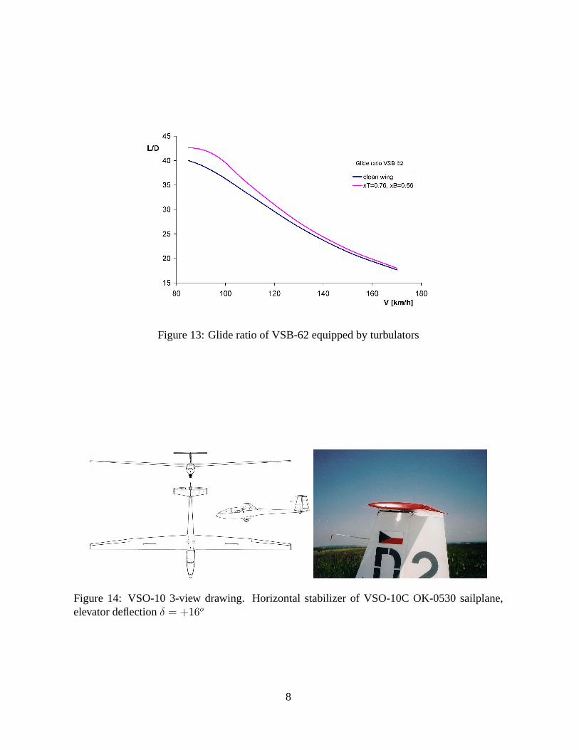
Figure 13: Glide ratio of VSB-62 equipped by turbulators
Figure 14: VSO-10 3-view drawing. Horizontal stabilizer of VSO-10C OK-0530 sailplane,elevator deflectionδ = +16o
8

-0.8
-0.6
-0.4
-0.2
0
0.2
0.4
0.6
0.8
0 0.002 0.004 0.006 0.008 0.01 0.012 0.014
c L
cD
Polars of NACA 64-009 K30 airfoil, Re=1e6, Xfoil 6.94, n=9
γ = 0o
γ = 0o, xt=xb=0.67γ = 5o
γ = 5o, xt=xb=0.67γ = 10o
γ = 10o, xt=xb=0.67
-0.6
-0.4
-0.2
0
0.2
0.4
0.6
0.8
1
0 0.005 0.01 0.015 0.02 0.025 0.03
c L
cD
Polars of NACA 64-009 K30 airfoil, Re=1e6, Xfoil 6.94, n=9
γ = 0o
γ = 0o, xt=xb=0.67γ = 15o
γ = 15o, xt=xb=0.67
Figure 15: Polars of NACA 64-009 airfoil,Re = 106
-1
-0.5
0
0.5
1
0 0.002 0.004 0.006 0.008 0.01 0.012 0.014
c L
cD
Polars of NACA 64-012 K50 airfoil, Re=1e6, Xfoil 6.94, n=9
γ = 0o
γ = 0o, xt=xb=0.48γ = 5o
γ = 5o, xt=xb=0.48γ = 10o
γ = 10o, xt=xb=0.48
0
0.5
1
1.5
0 0.01 0.02 0.03 0.04 0.05
c L
cD
Polars of NACA 64-012 K50 airfoil, Re=1e6, Xfoil 6.94, n=9
γ = 15o
γ = 15o, xt=xb=0.48γ = 20o
γ = 20o, xt=xb=0.48
Figure 16: Polars of NACA 64-012 airfoil,Re = 106
9