multicast vpn troubleshooting guide - mik · ii multicast vpn troubleshooting guide ol-10380-01...
TRANSCRIPT

Multicast VPN Troubleshooting GuideOL-10380-01
Corporate HeadquartersCisco Systems, Inc.170 West Tasman DriveSan Jose, CA 95134-1706 USAhttp://www.cisco.comTel: 408 526-4000
800 553-NETS (6387)Fax: 408 526-4100
Text Part Number: OL-10380-01

THE SPECIFICATIONS AND INFORMATION REGARDING THE PRODUCTS IN THIS MANUAL ARE SUBJECT TO CHANGE WITHOUT NOTICE. ALL STATEMENTS, INFORMATION, AND RECOMMENDATIONS IN THIS MANUAL ARE BELIEVED TO BE ACCURATE BUT ARE PRESENTED WITHOUT WARRANTY OF ANY KIND, EXPRESS OR IMPLIED. USERS MUST TAKE FULL RESPONSIBILITY FOR THEIR APPLICATION OF ANY PRODUCTS.
THE SOFTWARE LICENSE AND LIMITED WARRANTY FOR THE ACCOMPANYING PRODUCT ARE SET FORTH IN THE INFORMATION PACKET THAT SHIPPED WITH THE PRODUCT AND ARE INCORPORATED HEREIN BY THIS REFERENCE. IF YOU ARE UNABLE TO LOCATE THE SOFTWARE LICENSE OR LIMITED WARRANTY, CONTACT YOUR CISCO REPRESENTATIVE FOR A COPY.
The Cisco implementation of TCP header compression is an adaptation of a program developed by the University of California, Berkeley (UCB) as part of UCB’s public domain version of the UNIX operating system. All rights reserved. Copyright © 1981, Regents of the University of California.
NOTWITHSTANDING ANY OTHER WARRANTY HEREIN, ALL DOCUMENT FILES AND SOFTWARE OF THESE SUPPLIERS ARE PROVIDED “AS IS” WITH ALL FAULTS. CISCO AND THE ABOVE-NAMED SUPPLIERS DISCLAIM ALL WARRANTIES, EXPRESSED OR IMPLIED, INCLUDING, WITHOUT LIMITATION, THOSE OF MERCHANTABILITY, FITNESS FOR A PARTICULAR PURPOSE AND NONINFRINGEMENT OR ARISING FROM A COURSE OF DEALING, USAGE, OR TRADE PRACTICE.
IN NO EVENT SHALL CISCO OR ITS SUPPLIERS BE LIABLE FOR ANY INDIRECT, SPECIAL, CONSEQUENTIAL, OR INCIDENTAL DAMAGES, INCLUDING, WITHOUT LIMITATION, LOST PROFITS OR LOSS OR DAMAGE TO DATA ARISING OUT OF THE USE OR INABILITY TO USE THIS MANUAL, EVEN IF CISCO OR ITS SUPPLIERS HAVE BEEN ADVISED OF THE POSSIBILITY OF SUCH DAMAGES.
Multicast VPN Troubleshooting Guide © 2006 Cisco Systems, Inc. All rights reserved.
g y g y yNetworking Academy logo, Cisco Unity, Fast Step, Follow Me Browsing, FormShare, FrameShare, IGX, Internet Quotient, IP/VC, iQ Breakthrough, iQ Expertise, iQ FastTrack, the iQ Logo, iQ Net Readiness Scorecard, MGX, the Networkers logo, ScriptBuilder, ScriptShare, SMARTnet, TransPath, Voice LAN, Wavelength Router, and WebViewer are trademarks of Cisco Systems, Inc.; Changing the Way We Work, Live, Play, and Learn, and Discover All That’s Possible are service marks of Cisco Systems, Inc.; and Aironet, ASIST, BPX, Catalyst, CCDA, CCDP, CCIE, CCNA, CCNP, Cisco, the Cisco Certified Internetwork Expert logo, Cisco IOS, the Cisco IOS logo, Cisco Press, Cisco Systems, Cisco Systems Capital, the Cisco Systems logo, Empowering the Internet Generation, Enterprise/Solver, EtherChannel, EtherSwitch, FastHub, FastSwitch, GigaStack, IOS, IP/TV, LightStream, MICA, Network Registrar, Packet, PIX, Post-Routing, Pre-Routing, RateMUX, Registrar, SlideCast, StrataView Plus, Stratm, SwitchProbe, TeleRouter, and VCO are registered trademarks of Cisco Systems, Inc. and/or its affiliates in the U.S. and certain other countries.
All other trademarks mentioned in this document or Web site are the property of their respective owners. The use of the word partner does not imply a partnership relationship between Cisco and any other company. (0110R)

OL-10380-01
C O N T E N T S
Preface i-i
Document Purpose i-i
Target Audience i-i
Document Scope i-ii
C H A P T E R 1 mVPN Troubleshooting: Getting Started 1-1
Methodology of this Document 1-1
Test Setup 1-1
Assumptions and Prerequisites 1-2
Notations 1-3
Gathering Information 1-3
Tests for Enhanced mVPN Troubleshooting 1-4
Test A: Verifying the mVPN Setup for a Dummy Customer 1-4
Test B: Verifying the IP Multicast Core for the Default MDT Address Range 1-5
Common Configuration Errors 1-6
Releases and Platform Support 1-6
Default MDT Configuration 1-6
BGP Configuration 1-7
Customer Setup 1-7
Enabling Multicast in the Core and Between the PEs and CEs 1-7
Common Troubleshooting Scenarios 1-9
Data Multicast Flow Not Seen On One PE 1-9
Data Multicast Flow Not Seen on Several PEs 1-10
Control Plane Issues on the PE-CE Link(s) or Between PEs 1-11
C H A P T E R 2 Troubleshooting mVPNs 2-1
Reference Diagram for Troubleshooting an mVPN Setup 2-1
Section 1: Verifying the IP Multicast Core Settings for the Default MDT 2-3
Using the mtrace Command 2-9
Section 2: Verifying the PE-PE PIM Neighbor Relationship over the MTI 2-9
Gathering Information 2-10
Methodology 2-10
How to Use this Section 2-11
Checking the First Two PEs 2-11
iMulticast VPN Troubleshooting Guide

Contents
High Level Diagram of Steps to Follow when Troubleshooting the PEs Edge Settings of an mVPN for a subset of a Number (n) of PEs 2-12
Checking the PIM Neighborship Information on a Specific PE 2-15
Sample Output to Compare your Setup while Leveraging Figures 4 and 5 2-19
Checking the MTI Interface Status and BGP Settings on a Specific PE 2-23
Checking the Mroute State Information pertaining to the Default MDTGPA on a Specific PE 2-33
Section 3: Verifying the Customer-Facing Settings of the PEs 2-40
Assumptions 2-40
Main Topology for troubleshooting Customer-Facing Settings on the PEs 2-41
High-Level Diagram for Troubleshooting the Customer-Facing Settings on the PEs 2-43
Verifying Customer-Facing Settings on the PEC-RP 2-43
Verifying Customer-Facing Settings on the PEC-SRC 2-50
Verifying Customer-Facing Settings on the PEC-RCVR 2-56
Verifying Consistency of the Customer RP Settings 2-62
Verifying the Multicast Routes on the PEs in the VRF Context 2-62
Troubleshooting the PIM Adjacency with the CEs 2-68
Topology 2 2-70
Topology 3 2-73
Topology 4 2-77
Section 4: Verifying mVPN Data Flow 2-79
Assumptions 2-79
Topology for Data Flow Troubleshooting steps in the Default MDT 2-80
Customer Output 2-80
Verifying Mroute States on PEC-SRC and PEC-RCVR 2-81
Verify that the Multicast Stream is Received on PEC-SRC from C-SRC 2-84
Traffic Failure: No Multicast Traffic Received on PEC-SRC 2-86
Verify that the Multicast stream is switched to other local sites on PEC-SRC 2-88
Verifying that the Traffic is being Received on PEC-RCVR over the Global Default MDT Group Entry 2-90
Verifying that the (C-SRC, C-GPA) Traffic is Decapsulated on PEC-RCVR and sent to the mVRF 2-92
Sample Failure Scenario 2-93
C H A P T E R 3 Using Device Instrumentation for mVPN Troubleshooting 3-1
Using DI When Adding an mVPN Customer Site 3-1
Using SNMP for Monitoring an Existing mVPN 3-2
Overview of the Benefits of the mVPN MIB 3-3
Using DI to Optimize Troubleshooting Steps 3-4
Multicast NetFlow 3-4
iiMulticast VPN Troubleshooting Guide
OL-10380-01
Contents
Multicast Netflow: RPF Monitoring 3-5
Multicast Netflow: Performance and Memory Considerations 3-5
Using mrinfo for Troubleshooting Multicast Issues 3-5
Using the Mtrace Tool in Troubleshooting Multicast Issues 3-7
Traffic Failure Scenarios 3-8
A P P E N D I X A Sample Configurations for Testbed A-1
A P P E N D I X B Related Documents B-I
A P P E N D I X C Terms and Acronyms C-1
iiiMulticast VPN Troubleshooting Guide
OL-10380-01

Contents
ivMulticast VPN Troubleshooting Guide
OL-10380-01

Preface
This guide provides troubleshooting guidelines for mVPN issues that are specific to service provider mVPN setups. This guide can also be used for checking a new mVPN customer setup or adding a new site to an existing mVPN setup. It is assumed that the user has good understanding of MPLS VPNs, multicast VPNs, and their configuration.
To make the troubleshooting easier, this guide is organized as a set of interdependent flowcharts, tables and output examples that guide the user, step-by-step. This guide is not meant to be used for troubleshooting traditional IP multicast issues; for that, refer to the IP Multicast Troubleshooting Guide listed in Appendix B “Related Documents.”
Note Although this guide is comprehensive, it may not cover every possible mVPN troubleshooting scenario.
Document Purpose This guide provides mVPN troubleshooting guidelines for the edge PE (MTI, core and customer-facing settings), and basic troubleshooting guidelines for core multicast. It also provides some common configuration errors that should be considered.
Target AudienceThis guide is intended for the following users:
• Customers implementing mVPN
• Engineers who work in SP network operation centers (NOCs)
It is assumed that the user has prior understanding of the following:
– RFC 4364 (formerly RFC 2547)
– IP multicast
– Cisco’s implementation of mVPN
For details, refer to IP Multicast Troubleshooting Guide in Appendix B “Related Documents.”
iMulticast VPN Troubleshooting Guide
OL-10380-01

Preface Document Scope
Document ScopeThis document focuses on MVPN implementations leveraging the BGP MDT SAFI (SAFI 66), which was implemented in 12.0(29)S, 12.2(7)S and later IOS releases.
Table 1 lists the mVPN options that are covered in this guide:
The guide does not cover the following:
• Data MDT
• Inter AS mVPN
• Extranet mVPN
• Multihoming scenarios
• Platform dependent considerations and output
• SSM
It is important to note that although this document does not present troubleshooting information about SSM and Data MDTs, this should not be interpreted as a recommendation to not use such MVPN design improvements.
On the very opposite, Cisco strongly recommends the use of Data MDTs for optimization of an MVPN and SSM is the best PIM mode choice for Data MDTs when possible.
Table 2 lists the main troubleshooting areas for an mVPN setup.
Table 1 mVPN Options
Core PIM ModeCore RP Election Options VRF PIM Mode VRF RP Election Options
Default MDT Bidir
Pim-SM with SPT equals to 0
Static
AutoRP
Customer Multicast Groups
PIM-SM with SPT equals to 0
On customer side:
static and AutoRP
Table 2 Multicast VPN Troubleshooting Areas
Section Description
Common Configuration Errors, page 1-6
This section lists and describes some common mVPN configuration errors that the user of this guide should consider before getting into the main troubleshooting sections.
Section 1: Verifying the IP Multicast Core Settings for the Default MDT, page 2-3
This section provides troubleshooting guidelines for the core mVPN address range. The following are considered:
• PIM modes and source path tree (SPT) threshold related issues
• RP settings on P or PE routers.
iiMulticast VPN Troubleshooting Guide
OL-10380-01

Preface Document Scope
Section 2: Verifying the PE-PE PIM Neighbor Relationship over the MTI, page 2-9
This section provides troubleshooting guidelines for the following:
• For a given PE, how to ensure that the MTI tunnel interface is UP and associated to the VRF
• How to ensure that the BGP and VRF settings for the default mdt are properly configured
• How to ensure that the PE is able to establish PIM peerings with remote PEs over the MTI
• How to ensure that the (*,GPA) and potential (S,GPA) are in the MRIB, and that the IIL, OIL and flags are appropriate
Section 3: Verifying the Customer-Facing Settings of the PEs, page 2-40
This section provides troubleshooting guidelines for determining whether the issue is on the SP network or the enterprise network. The following are included:
• Checking VRF specific PIM and RP settings on the PEs
• Analyzing customer specific mroute states on the PEs
Section 4: Verifying mVPN Data Flow, page 2-79
This section describes how to troubleshoot the mVPN data flow. This section only covers data flow on default MDT; not data MDT.
Chapter 3, “Using Device Instrumentation for mVPN Troubleshooting.”
This section describes device instrumentation (DI) that are specific to mVPN setups
Table 2 Multicast VPN Troubleshooting Areas (continued)
Section Description
iiiMulticast VPN Troubleshooting Guide
OL-10380-01

Preface Document Scope
ivMulticast VPN Troubleshooting Guide
OL-10380-01
OL-10380-01
C H A P T E R 1
mVPN Troubleshooting: Getting StartedThis chapter describes the following:
• The methodology used throughout the document.
• The first steps to take before troubleshooting an MVPN setup.
• Information that should be taken into account before starting to troubleshoot mVPN setups.
• Common configuration errors that should be considered when troubleshooting mVPN networks.
• Common troubleshooting scenarios.
Methodology of this DocumentThis section describes the methodology used in this document.
Test SetupFigure 1-1 shows the test setup that was used for the troubleshooting techniques described in this guide. Note the following in this setup:
• C-RP, P-RP, and RR are outside of the forwarding path.
• OSPF is used as IGP in the core.
• Default MDT: VRF RED 239.0.0.10.
• VRF RED customer groups belong to address range: 225.1.1.1-> 225.1.1.10.
• Cisco IOS Release12.0(31)S1 is running on all routers.
• Traffic on the Customer source was simulated using a Test Tool (SRC1) and Received Traffic was also measured using a Test Tool (RCVR 12, 2, 3).
1-1Multicast VPN Troubleshooting Guide

Chapter 1 mVPN Troubleshooting: Getting Started Methodology of this Document
Figure 1-1 Test Setup
Assumptions and PrerequisitesBefore going into the main troubleshooting sections that start with Chapter 2, “Troubleshooting mVPNs,” consider the following assumptions:
• Unicast VPN traffic forwarding is working as intended.
• The IP multicast core is properly configured.
PE1
192.
168.
2.0/
24
Rcvr2
CE2
e0/0
s0/0
s0/0
s1/0
s0/0
s0/0
s2/0s1/0
s3/0
e0/0
C-RPe1/0
s0/0
s0/0
s0/0
e2/0
s0/0
s3/0
s0/0
s1/0
e0/0
s4/0
s0/0
s1/0
s1/0
s1/0
P12
P13
192.168.202.0/24
172.16.1.0/24
P-RP172.16.212.0/24
Rcvr3 192.168.3.0/24
172.16.13.0/24
PE2 172.16.2.0/24
RR
s0/0s2/0
s1/0
e0/0
s1/0
s0/0
s0/0
P11
192.
168.
22.0
/24
Rcvr12
CE12
CE1
192.
168.
12.0
/24
192.
168.
1.0/
24
Src1
172.
16.1
2.0/
24
172.
16.1
13.0
/24
172.
16.2
13.0
/24172.16.23.0/24
192.
168.
11.0
/24
192.168.112.0/24
172.16.3.0/24
172.16.111.0/24
PE3
CE3
192.
168.
33.0
/24
Lo0:192.168.100.2 Lo0:192.168.100.202
Lo0:172.16.100.2
Lo0:192.16.100.12
Lo0:172.16.100.1
Lo0:172.16.100.11
Lo0:192.168.100.1
Lo0:192.168.100.3
Lo0:172.16.100.200
Lo0:172.16.100.3
Lo0:172.16.100.13
Lo0:172.16.100.100
Lo0:172.16.100.2
1418
41
1-2Multicast VPN Troubleshooting Guide
OL-10380-01
Chapter 1 mVPN Troubleshooting: Getting Started Methodology of this Document
• All PE-CE interfaces are enabled for both unicast and multicast (PIM); otherwise, RPF does not work as intended.
• All PE platforms support the mVPN features and are running the appropriate Cisco IOS release.
For more information, refer to the Cisco Feature navigator:
http://tools.cisco.com/ITDIT/CFN/jsp/index.jsp
• The IOS release supports the new BGP MDT SAFI.
When dealing with mVPN issues encountered for multiple customers, focus on resolving the issues for one customer at a time.
NotationsFor acronyms and notation information, refer to Appendix C, “Terms and Acronyms.” Note that some of the acronyms are used for the purpose of this document only.
Gathering InformationBefore starting troubleshooting, gather as much information as possible about the mVPN issues and the customer’s multicast network characteristics. The following are examples of customers’ information to gather:
• C-RP IP address(es)
• C-Sources IP address(es)
• C-receivers IP address(es)
• C-sources traffic rates
• C-GPA
This information can be used to identify the PEC-RCVR, PEC-SRC, PEC-RP, and default MDT GPA.
For the definition of these and other related terms used in this guide, refer to Appendix C, “Terms and Acronyms.”
The following are examples of customer issues:
• Customers have problems connecting to a specific site (PE).
• No customer has multicast connectivity.
• Customer’s multicast traffic is flowing, but not at the expected rates (partial traffic rates).
• The PEs cannot see each other as PIM neighbors over the MTI.
• One group (S,G) or (*,G) of a customer has issues.
1-3Multicast VPN Troubleshooting Guide
OL-10380-01

Chapter 1 mVPN Troubleshooting: Getting Started Methodology of this Document
Tests for Enhanced mVPN TroubleshootingBecause troubleshooting SP networks for unicast and multicast VPN involves many elements, the tests in Table 1 can be used to help the troubleshooting steps, if they are incorporated in the troubleshooting process. They provide sanity checks of the core routers and the core-facing PEs.
It is understood that some environments might not allow you to create new configuration states on a live network, so the verification of the core via a dummy vrf might not be feasible.
Note Ensure that the parameters for these tests are correctly configured so as to avoid false positive results.
Note Ensure that the dummy default mdt group address is not used for any customer.
Table 1 High level description of the Sanity Tests
Test A: Verifying the mVPN Setup for a Dummy Customer
The following test configuration creates a “dummy” or “test” mVPN customer. In this test, an mVRF is set up on all PEs for this test customer. Then, a ping is performed to check that all PEs in the test mVPN reply, which proves that the core and the generic BGP settings are correct for the mVPN MDT test address.
The test will be useful to quickly isolate MTI and PIM peering issues.
Note The RP used for the test Group address should be the same as the one used for the mVPNs you are troubleshooting.
Note The loopback used for the test VRF should not be a pre-existing loopback. Each PE belonging to the test mVPN will have such a loopback. PE loopback IP addresses can belong to any range but they cannot overlap.
Tests Description
Test A: Verifying the mVPN Setup for a Dummy Customer
Verifies the core and edge settings for a test customer using all PE sites. Success of this test validates that the multicast core settings for the default mdt address range and the BGP settings on all PEs are correctly configured. If this test fails, refer to the troubleshooting guidelines provided in Section 2: Verifying the PE-PE PIM Neighbor Relationship over the MTI, page 2-9.
Test B: Verifying the IP Multicast Core for the Default MDT Address Range
Verifies the core settings for all PEs sites. Success of this test validates that the multicast core settings for the default mdt address range on all core P, PEs, and RP routers are correctly configured.
If this test fails, refer to the troubleshooting guidelines provided in Section 1: Verifying the IP Multicast Core Settings for the Default MDT, page 2-3.
1-4Multicast VPN Troubleshooting Guide
OL-10380-01

Chapter 1 mVPN Troubleshooting: Getting Started Methodology of this Document
Step 1 The following configuration is recommended on all the PEs, in addition to the standard mVPN configuration, for test A:
ip vrf test255 rd X:Y route-target export W:Z route-target import W:Z
mdt default 239.0.0.255ip multicast-routing vrf test255
interface Loopback255 ip vrf forwarding test255 ip address 172.16.255.1 255.255.255.255 no ip directed-broadcast ip pim sparse-dense-mode ip igmp join-group 225.1.1.255
router bgp 1address-family ipv4 vrf test255redistribute connectedend
Note The rd X:Y, route-target W:Z, and the MDT default 239.0.0.255 address from MDT GPA range cannot be assigned to any existing customer. It should be the same on all PEs. One method to ensure availability it to check the Route-Reflector (or multiple Route-Reflectors if partitioning is used).
Step 2 After the above configuration is performed and you enter a ping from one of the PEs, a reply is generated and displayed from all remote PEs:
PEC-SRC#ping vrf test255 225.1.1.255
Type escape sequence to abort.Sending 1, 100-byte ICMP Echos to 225.1.1.255, timeout is 2 seconds:
Reply to request 0 from 172.16.255.1, 24 msReply to request 0 from 172.16.100.2, 72 msReply to request 0 from 172.16.100.3, 72 ms
Test B: Verifying the IP Multicast Core for the Default MDT Address Range
This test configuration verifies that the SP core is functional for the mVPN address range.
Step 1 For this test, each PE should be configured with an extra loopback (not the one used as router ID for IGP, LDP, or BGP). The following should be configured on the loopback:
ip igmp join-group 239.0.0.254ip pim sparse mode
Note The address from the default MDT GPA range cannot be assigned to any customer MDT.
This example assumes that the default MDT range is 239.x.x.x/8 and 239.0.0.254 is not in use. If this address is used, use a non-assigned address from the MDT default range.
1-5Multicast VPN Troubleshooting Guide
OL-10380-01

Chapter 1 mVPN Troubleshooting: Getting Started Common Configuration Errors
Step 2 After the above configuration is performed and you enter the ping command from one of the PEs, a reply is generated and displayed from all remote PEs. Ensure that you enter the ping source address precisely to avoid multiple echo replies:
PEC-SRC#ping ipTarget IP address: 239.0.0.254Repeat count [1]: Datagram size [100]: Timeout in seconds [2]: Extended commands [n]: yInterface [All]: loopback 0Time to live [255]: Source address: Type of service [0]: Set DF bit in IP header? [no]: Validate reply data? [no]: Data pattern [0xABCD]: Loose, Strict, Record, Timestamp, Verbose[none]: Sweep range of sizes [n]: Type escape sequence to abort.Sending 1, 100-byte ICMP Echos to 239.0.0.254, timeout is 2 seconds:
Reply to request 0 from 172.16.100.1, 20 ms Reply to request 0 from 172.16.2.2, 84 ms Reply to request 0 from 172.16.3.3, 44 ms
• There will be a ping reply from core-facing interfaces of all remote PEs configured for the igmp join-group 239.0.0.254 command in the global interface.
• There will be a ping reply from the IP address of the local loopback interface configured for the igmp join-group 239.0.0.254 command.
Common Configuration ErrorsRefer to Appendix A and the Design Guides in the References Section for full configurations and design guidance.
Consider the following common errors when troubleshooting an mVPN configuration:
Releases and Platform Support
• Use Feature Navigator to ensure that there is support for mVPN in the platforms and in the Cisco IOS release being used. For more information refer to the following URL (note that a Cisco user ID and password is required).
http://tools.cisco.com/ITDIT/CFN/jsp/index.jsp
• Ensure that the chosen release supports the latest BGP MDT SAFI implementation.
Default MDT Configuration
• Ensure that the range of default MDT is configured with the same PIM mode and RP election option on all the PEs.
• Ensure that the same MDT default group address is defined on all PEs that belong to a given mVPN.
1-6Multicast VPN Troubleshooting Guide
OL-10380-01

Chapter 1 mVPN Troubleshooting: Getting Started Common Configuration Errors
BGP Configuration
Loopback and BGP Next Hop Configuration
• Ensure that the BGP update source interface from which the MTI takes its properties (normally a loopback) is configured for PIM.
• Ensure that the MTI is unnumbered to the appropriate BGP update-source interface. Normally this is the default, unless the bgp next-hop command is used in the VRF context and overrides the default.
• Ensure that the local PE router uses the same update-source/ next hop reference interface to peer with all the remote PEs that belong to the mVPN.
BGP MDT SAFI Configuration
• Configure the Address family MDT SAFI neighbors exactly as the VPNv4 address family (Neighbor addresses and update source values).
Customer Setup
• Ensure that C-SRC is generating multicast stream with the appropriate TTL value.
Enabling Multicast in the Core and Between the PEs and CEs
Checking the Pim Settings
• Ensure that PIM is enabled on the core facing interfaces; use the show ip pim interface command to verify.
• Ensure that the ip multicast-routing global command is enabled.
• Ensure that the ip multicast-routing vrf command is enabled.
• Ensure that the all PE-CE interfaces on the PEs are enabled for the appropriate PIM mode. Use the show ip pim vrf vrf-name neighbors command to verify.
• Verify that the PIM SPT threshold value is consistent.
Multicast Boundaries and ACLs
• Ensure that ACLs, multicast-boundary, multicast ttl-threshold, IP PIM neighbor filter statements, and multicast rate-limit configured on the PE-CE interface or on the core links are not blocking any traffic.
Checking the RP Settings
• Ensure that P-RP is known and reachable by all P and PE routers.
• Ensure that Group-to-RP mapping is consistent on all Ps and PEs. If the PE router is, for instance, configured with an RP address that is different from the one configured on another P or PE router, the following error may be generated:%PIM-6-INVALID_RP_JOIN: Received (*, GPA) Join from <PIM-NBR> for invalid RP <RP-ADDR> [NOTE PIM-NBR is printed out all 0s before the update of CSCei28317].
• For PIM SM, ensure that all routers in the network are configured with the same ip pim spt-threshold [0|infinity] command (function of the Multicast address range).
• If using PIM Bidir with static RP, verify that the ip pim bidir- enable command is enabled on all core and edge routers.
1-7Multicast VPN Troubleshooting Guide
OL-10380-01

Chapter 1 mVPN Troubleshooting: Getting Started Common Configuration Errors
• Verify the following RP settings:
– Verify that for PIM SM and Bidir with static RP the ip pim rp-address address [group-list acl] [override] [bidir] command is enabled on the core and edge routers.
– The group-list allows a group range to be specified.
– The default is ALL multicast groups or 224.0.0.0/4.
– The override keyword permits the statically defined RP address to take precedence over Auto-RP learned Group-to-RP mapping information. The default behavior without this keyword is that Auto-RP learned information has precedence over static information.
• Check the following potential RP-filters:
– Check for any filters using the ip pim accept-rp command and verify that it is configured to allow the RP-address, including on the RP itself.
– Check for ip pim accept-register filters command on the RP.
– Check for ip pim rp-announce-filter rp-list group-list command on the mapping agent for Auto-RP.
– Check for group-lists or ACL post-pended to commands, such as ip pim send-rp-announce and ip pim rp-address.
PIM SM with AutoRP
The AutoRP groups (224.0.1.39 and 224.0.1.40) need to be densely switched, which is achieved by one of the following:
• Enabling PIM sparse-dense mode on all PIM interfaces.
• Enabling PIM sparse-mode on all PIM interfaces and enabling the ip pim autorp listener command.
Note If a static RP is defined as an RP of last resort, which is most of the time for the router itself, ensure that AutoRP groups are denied by the ACL in the static RP command line.
If both of the above two conditions are met and if the show ip pim rp mapping command still does not display any RP mappings learned through AutoRP, then:
– Check the show ip mroute 224.0.1.39 command on the mapping agent and verify that you see the (S,224.0.1.39), where S equals the RP address.
– Ensure that if there is a filter list on the mapping agent, it allows the valid RP address/group range.
– For more information, refer to the following URL: http://www.cisco.com/en/US/tech/tk828/technologies_configuration_example09186a00801cb923.shtml
– On the PE/P routers, ensure that there are RP discovery messages from the mapping agent. Enter the show ip mroute 224.0.1.40 command on a router and see if there is the following: (S,224.0.1.40), where S equals the mapping agent.
1-8Multicast VPN Troubleshooting Guide
OL-10380-01

Chapter 1 mVPN Troubleshooting: Getting Started Common Configuration Errors
Common Troubleshooting ScenariosThe following tables provide possible specific mVPN-related scenarios.
• Data Multicast Flow not seen on one PE
• Data Multicast Flow not seen on several PEs
• Control plane issues
Note This section is not meant to replace the more detailed troubleshooting sections, but rather to provide some level of guidance and some precise steps to take in case of common troubleshooting circumstances.
The section assumes that unicast VPN connectivity to and from the customer sites hosted on the corresponding PE is working well.
Data Multicast Flow Not Seen On One PE
Table 1-2 Scenarios for Data Flow Issues on one PE
Scenario Recommended Steps
No customer connected to one given PE can receive or send multicast data traffic
1. Apply the guidelines described in Common Configuration Errors, page 1-6 for each specific C-Src and C-GPA of this customer.
2. Perform Test A: Verifying the mVPN Setup for a Dummy Customer andTest B: Verifying the IP Multicast Core for the Default MDT Address Range
a. If Test A: Verifying the mVPN Setup for a Dummy Customer fails, first check Test B: Verifying the IP Multicast Core for the Default MDT Address Range.
b. If Test B is successful and Test A fails, check the PE edge settings (refer to Section 2: Verifying the PE-PE PIM Neighbor Relationship over the MTI, page 2-9 for troubleshooting guidelines).
c. If both Test A and B fail, check the core settings (refer to Section 1: Verifying the IP Multicast Core Settings for the Default MDT, page 2-3 for troubleshooting guidelines).
3. If you have not implemented Test A and Test B, focus on one customer and apply the guidelines in Section 2: Verifying the PE-PE PIM Neighbor Relationship over the MTI, page 2-9 for that customer’s default mdt-GPA.
4. Refer to Section 4: Verifying mVPN Data Flow, page 2-79 for any data flow related issues.
One customer has a data issue on a given PE site, while other customers do not
1. Refer to Common Configuration Errors, page 1-6 to ensure there is no common error in the configuration.
2. Focus on the corresponding PE(s).
3. Ensure unicast VPN connectivity to and from the customer sites hosted on this PE.
4. Apply the guidelines provided in Section 2: Verifying the PE-PE PIM Neighbor Relationship over the MTI, page 2-9) on this PE for the customer’s default mdt-GPA.
5. Check the data Plane using Section 4: Verifying mVPN Data Flow, page 2-79
1-9Multicast VPN Troubleshooting Guide
OL-10380-01
Chapter 1 mVPN Troubleshooting: Getting Started Common Configuration Errors
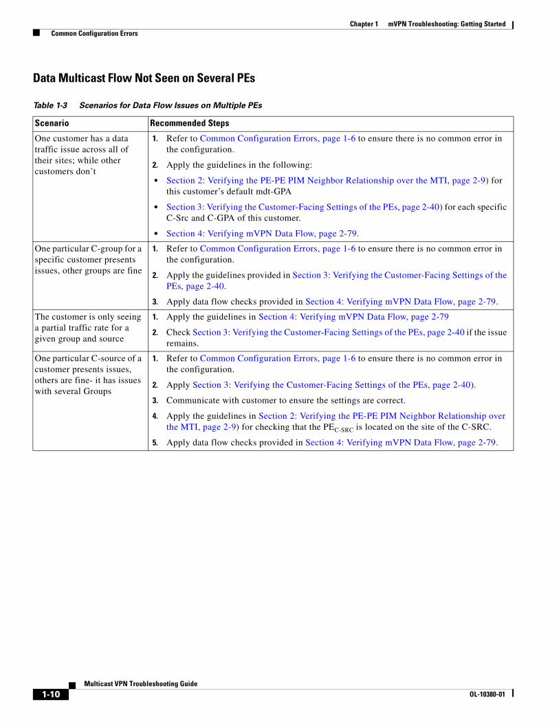
Data Multicast Flow Not Seen on Several PEs
Table 1-3 Scenarios for Data Flow Issues on Multiple PEs
Scenario Recommended Steps
One customer has a data traffic issue across all of their sites; while other customers don’t
1. Refer to Common Configuration Errors, page 1-6 to ensure there is no common error in the configuration.
2. Apply the guidelines in the following:
• Section 2: Verifying the PE-PE PIM Neighbor Relationship over the MTI, page 2-9) for this customer’s default mdt-GPA
• Section 3: Verifying the Customer-Facing Settings of the PEs, page 2-40) for each specific C-Src and C-GPA of this customer.
• Section 4: Verifying mVPN Data Flow, page 2-79.
One particular C-group for a specific customer presents issues, other groups are fine
1. Refer to Common Configuration Errors, page 1-6 to ensure there is no common error in the configuration.
2. Apply the guidelines provided in Section 3: Verifying the Customer-Facing Settings of the PEs, page 2-40.
3. Apply data flow checks provided in Section 4: Verifying mVPN Data Flow, page 2-79.
The customer is only seeing a partial traffic rate for a given group and source
1. Apply the guidelines in Section 4: Verifying mVPN Data Flow, page 2-79
2. Check Section 3: Verifying the Customer-Facing Settings of the PEs, page 2-40 if the issue remains.
One particular C-source of a customer presents issues, others are fine- it has issues with several Groups
1. Refer to Common Configuration Errors, page 1-6 to ensure there is no common error in the configuration.
2. Apply Section 3: Verifying the Customer-Facing Settings of the PEs, page 2-40).
3. Communicate with customer to ensure the settings are correct.
4. Apply the guidelines in Section 2: Verifying the PE-PE PIM Neighbor Relationship over the MTI, page 2-9) for checking that the PEC-SRC is located on the site of the C-SRC.
5. Apply data flow checks provided in Section 4: Verifying mVPN Data Flow, page 2-79.
1-10Multicast VPN Troubleshooting Guide
OL-10380-01

Chapter 1 mVPN Troubleshooting: Getting Started Common Configuration Errors
Control Plane Issues on the PE-CE Link(s) or Between PEs
Table 1-4 Scenarios for Control Plane Issues on one or more PE(s)
Scenario Recommended Steps
The PIM neighborship CE-PE session is down or needs to be checked on a specific Site
1. Refer to Common Configuration Errors, page 1-6 to ensure there is no common error in the configuration.
2. Focus on that specific PE.
3. Apply the guidelines provided in Section 3: Verifying the Customer-Facing Settings of the PEs, page 2-40).
4. Communicate with the customer to check the customer-side network setup.
5. Apply the guidelines provided in Section 4: Verifying mVPN Data Flow, page 2-79.
The PEs do not see each other as PIM neighbors over the MTI
1. Refer to Common Configuration Errors, page 1-6 to ensure there is no common error in the configuration.
2. Perform Test A: Verifying the mVPN Setup for a Dummy Customer andTest B: Verifying the IP Multicast Core for the Default MDT Address Range
a. If Test A: Verifying the mVPN Setup for a Dummy Customer fails, first check Test B: Verifying the IP Multicast Core for the Default MDT Address Range.
b. If Test B is successful and Test A fails, check the PE edge setting (refer to Section 2: Verifying the PE-PE PIM Neighbor Relationship over the MTI, page 2-9 for troubleshooting guidelines).
c. If both Test A and B fail, check the core settings (refer to Section 1: Verifying the IP Multicast Core Settings for the Default MDT, page 2-3 for troubleshooting guidelines).
3. If you have not implemented Test A and Test B, apply the guidelines provided in Section 1: Verifying the IP Multicast Core Settings for the Default MDT, page 2-3).
4. Apply the guidelines provided in Section 2: Verifying the PE-PE PIM Neighbor Relationship over the MTI, page 2-9) to the PEs.
1-11Multicast VPN Troubleshooting Guide
OL-10380-01

Chapter 1 mVPN Troubleshooting: Getting Started Common Configuration Errors
1-12Multicast VPN Troubleshooting Guide
OL-10380-01

OL-10380-01
C H A P T E R 2
Troubleshooting mVPNsThis chapter describes how to troubleshoot the mVPN network. The following sections are included:
• Reference Diagram for Troubleshooting an mVPN Setup, page 2-1
• Section 1: Verifying the IP Multicast Core Settings for the Default MDT, page 2-3
• Section 2: Verifying the PE-PE PIM Neighbor Relationship over the MTI, page 2-9
• Section 3: Verifying the Customer-Facing Settings of the PEs, page 2-40
• Section 4: Verifying mVPN Data Flow, page 2-80
Reference Diagram for Troubleshooting an mVPN SetupFigure 2-1 shows the main reference diagram for troubleshooting an mVPN setup. This diagram is the point of reference for all troubleshooting described in this guide.
2-1Multicast VPN Troubleshooting Guide

Chapter 2 Troubleshooting mVPNs Reference Diagram for Troubleshooting an mVPN Setup
Figure 2-1 High-level Diagram for Troubleshooting an mVPN Setup
C h e c k C u s to m e r-fa c in g m u lt ic a s ts e tu p (S e c tio n 3 )
C h e c k S e c tio n 4
C h e c k fo r b a s ic c o n fig u ra tio n m is ta k e s u s in g th e “C o m m o n C o n fig u ra tio nE rro rs ” S e c tio n
N o c u s to m e r m u lt ic a s t tra ff ic flo w in gy e t o r n o c u s to m e r s p e c if ic in foa v a ila b le ?
S e le c t a n M V P N G P A to w o rk w ith .
F o c u s o n o n e m V P N c u s to m e r.F o r th is c u s to m e r id e n tify a C -G P A a n d a C -S o u rc e w ith to w o rk .
C h e c k e d g e s e tu p(P E ro u te rs )
fo r th is m V P N(S e c tio n 2 )
T h is w a s fo r a s p e c ific c u s to m e r’s C -G P A a n d C -S o u rc e . R e u s e th is flo w c h a rt to c h e c k a n ya d d it io n a l c o m b in a tio n .
S e tu p is h e a lth y .(c o re m u ltic a s t a n d m V R Fe d g e c o n fig u ra tio n s )
A p p ly S e c tio n 1 ;c h e c k th e c o re fo rth e G P A
H o o k s to s e c tio n 1
O K
A p p ly T e s t AV e rify m V P N tra ff ic fo r te s t c u s to m e ris w o rk in g .
If T e s t A is n o t c o n fig u re d , g o toA .1 .0
T e s t A F a ils
C h e c k P E e d g es e tt in g s fo r th isc u s to m e r C -G P A (A p p lyS e c tio n 2 )
H o o k s to S e c tio n 2
H o o k s to S e c tio n 1
C h e c k P E c o res e tt in g s fo r th eG P A u s e d fo rth is c u s to m e r’sm V P N (A p p lyS e c tio n 1 )
A p p ly T e s t B if c o n fig u re dto v e r ify th e C o re fo r th e
m V P N ra n g e
T e s t BF a ilsA .1 .0
T e s t B s u c c e s s fu l
T e s t A s u c c e e d s
2-2Multicast VPN Troubleshooting Guide
OL-10380-01

Chapter 2 Troubleshooting mVPNs Section 1: Verifying the IP Multicast Core Settings for the Default MDT
Section 1: Verifying the IP Multicast Core Settings for the Default MDT
This section provides a basic outline to help troubleshoot IP multicast in the SP core, with an emphasis on the MDT default address.
Failure of proper operation of multicast in the SP’s core network can impact all mVPN customers’ traffic. This section does not provide details on traditional IP multicast troubleshooting. For any traditional IP multicast troubleshooting, refer to the IP Multicast Troubleshooting Guide at the following URL:
http://www.cisco.com/en/US/tech/tk828/technologies_tech_note09186a0080094b55.shtml
The following are possible configuration errors that can be detected:
• Misconfigured PIM configurations on any PE, P, or P-RP routers
• Inconsistent SPT threshold setting
• Inconsistent RP information across the SP core
• RPF check failure for the RP or one of the sources
The following information should be available:
• GPA
• PIM mode (SM or Bidir) for the GPA
• Core RP option (static or Auto RP) and RP IP address
• SPT threshold setting
Ensure that at least two PEs are configured for this mVPN.
Note For this section, we recommend that you implement the test described in Test B: Verifying the IP Multicast Core for the Default MDT Address Range, page 1-5.
Most of the potential issues identified when troubleshooting the IP multicast core for a default mdt group address are IP multicast issues. For this reason, this section focuses only on the IP address range corresponding to the default mdt group address and not on all IP multicast groups that might use the IP multicast core.
Figure 2-2 highlights the areas that are specific to an mVPN scenario where the multicast group address is an default mdt multicast address. Following the diagram are samples of output that can be used for guidance. These output examples correspond to the show commands from the diagram.
Figure 2-2 shows a state machine that provides high level guidance. Select an initial core router (PE, RP, or P router) to start with, similar to troubleshooting traditional IP multicast. You can then move, hop-by-hop, as necessary on any additional core router, to verify the IP multicast core for the GPA address configured.
2-3Multicast VPN Troubleshooting Guide
OL-10380-01

Chapter 2 Troubleshooting mVPNs Section 1: Verifying the IP Multicast Core Settings for the Default MDT
Figure 2-2 Troubleshooting the Multicast SP Core for a given GPA Address
C h e c k f o r s h o w i p m r o u t e < G P A >
D o y o u s e e t h e( * , G P A ) e n t r y ?
U s e d e b u g i p p i m < G P A > t o v e r i f y i f ( * , G ) j o i n i s r e c e i v e d I f G P A i s a t e s t M D T a d d r e s s , s e e N o t e 3 .
D o y o u s e e t h e ( S , G P A ) e n t r y w h e r e S = P E T u n n e l I P a d d r e s s ?
C h e c k f o r s h o w i p m r o u t e < G P A > S e e N o t e 4 . C h e c k P I M m o d e i s c o r r e c t o n a l lr o u t e r s .
s h o w i p m r o u t e < G P A > :
O n P r o u t e r sT h e I n c o m i n g I n t e r f a c e [ R f l a g o n t h e ( S , G P A ) ] = R P F i n t e r f a c e t o t h e P - R PT h e i n c o m i n g I n t e r f a c e [ N O R f l a g o n t h e ( S , G P A ) ] = R P F I n t e r f a c e t o S o u r c e ‘ S ’ .T h e o u t g o i n g i n t e r f a c e s = o n w h i c h t h e ( S , G ) j o i n s a r e r e c e i v e d + O I L o f ( * , G ) m i n u s t h e I I L
O n t h e P - R PT h e i n c o m i n g I n t e r f a c e = R P F I n t e r f a c e t o S o u r c e ‘ S ’ .T h e o u t g o i n g i n t e r f a c e s = O I L o f ( * , G ) – I I L
O n P E R o u t e r ( w h e r e S = l o c a l i p a d d r e s s )T h e i n c o m i n g I n t e r f a c e = T u n n e l S o u r c e i n t e r f a c eT h e o u t g o i n g i n t e r f a c e s = o n w h i c h t h e ( S , G ) j o i n s a r e r e c e i v e d
O n P E R o u t e r ( w h e r e S = r e m o t e P E i p a d d r e s s )T h e i n c o m i n g I n t e r f a c e = R P F I n t e r f a c e t o S o u r c e ‘ S ’T h e o u t g o i n g i n t e r f a c e s = m V R F n a m e
N O
Y E S
N O
Y E S
V e r i f y t h e R P F p a t h f r o m P E R P a n d R P P E a n d i s o l a t e b a s i c P I M / M u l t i c a s t m is - c o n f i g u r a t i o n s i n t h ep a t h .“ m t r a c e < R P - A d d r e s s > < P E - a d d r e s s > < G P A > ”“ m t r a c e < R P - A d d r e s s > < P E - a d d r e s s > ”“ m t r a c e < P E - A d d r e s s > < R P - a d d r e s s > < G P A > ”“ m t r a c e < P E - A d d r e s s > < R P - a d d r e s s > ”
O n a P E r o u t e r , u s e s h i p p i m m d t a n d s h i n t t u n n e l xt o c h e c k s t a t u s o f M T I a n d B G P s e t t i n g s . R e a d N o t e 1
K e e p c h e c k i n g o t h e r c o r e r o u t e r s a s n e c e s s a r y .F o c u s o n t h i s c u r r e n t M D T g r o u p a d d r e s s o n l y .
o k
F o r a g i v e n r o u t e r o f t h e c o r e ( P , P E , R P )
C h e c k t h e ( * , G P A ) e n t r y i n t h e o u t p u t : s e e n o t e 2 a n d u s e t h e b e l o w n e x t s t e p s o n a p e r r o u t e r “ r o l e ”b a s i s
O n P r o u t e r c h e c k :F l a g s : S f o r P I M - S M a n d B f o r b i d i rT h e I n c o m i n g I n t e r f a c e = R P F i n t e r f a c e t o t h e P - R PR P F n b r = P I M n e i g h b o rT h e o u t g o i n g i n t e r f a c e i s w h e r e t h e ( * , G ) j o i n s a r e r e c e i v e d – I I L
O n P E r o u t e r c h e c k :F l a g s : S C F Z ( a n d J i f s p t - t h r e s h o l d i s N O T s e t t o i n f i n i t y ) , B C Z i n c a s e o f B i d i rT h e I n c o m i n g I n t e r f a c e = R P F i n t e r f a c e t o t h e P - R P R P F n b r = P I M n e i g h b o rT h e o u t g o i n g i n t e r f a c e = m V R F n a m e .
O n t h e P - R P c h e c k :T h e I n c o m i n g I n t e r f a c e = N U L L a n d t h e R P F n b r = 0 . 0 . 0 . 0T h e o u t g o i n g i n t e r f a c e s a r e t h e i n t e r f a c e s f o r t h e m u l t i c a s t o u t g o i n g p a t h t o w a r d s t h e r e c e i v e r P E s
D o n e w i t h c h e c k i n g c o r e r o u t e r s
[ o t p i o n a l ] : P e r f o r m M t r a c e a s n e e d e d m a i n l y o n t h e P E s o r R P
G o b a c k t o t h ef i g u r e t h a t
r e f e r r e d y o u t ot h i s f i g u r e
B
A .
2-4Multicast VPN Troubleshooting Guide
OL-10380-01

Chapter 2 Troubleshooting mVPNs Section 1: Verifying the IP Multicast Core Settings for the Default MDT
Notes for Figure 2-2
Note 1
• Ensure that the MTI and BGP configurations are correct.
• If the configurations are incorrect, correct them, and then re-check using the show ip mroute GPA command.
• If the router is not a PE or RP, note that the P router might not be part of the multicast core tree for this MDT address.
• Check regular PIM settings for the P or RP router if the (*,GPA) entry is not there and it should be. Refer to the traditional multicast troubleshooting documents for more information.
Note Refer to the IP Multicast Troubleshooting Guide to solve general IP multicast issues: http://www.cisco.com/en/US/tech/tk828/technologies_tech_note09186a0080094b55.shtml
• When the issue is corrected, re-check by following this flowchart from the top.
Note 2
• Verify the following for all the core P, PE, and RP routers:
– The RP address is P-RP.
– The flag is S for PIM-SM and B for the Bidir case.
• Refer to Sample Output for Figure 2-2, page 2-5 as a reference (as needed).
• As most of the potential issues here are IP multicast-related, correct them using traditional IP multicast troubleshooting guides, then re-check using the show ip mroute GPA output.
Note 3
It seems that we are not receiving any (*,G) join. If the MDT group address is a test MDT address (for example: address used for Test B setup), ensure that it is not a false positive result.
Note 4
This might be normal if the core is configured for PIM Bidir. In all other cases we should at least have the local PEs (S,GPA) if the MTI/BGP is configured correctly.
Sample Output for Figure 2-2
The following sample output is obtained from the show ip mroute command on the PE and P routers (nonRP) in the Bidir mode. Note the B flag. Also note the MDT Z flag.
PE1#show ip mroute 239.0.0.10IP Multicast Routing TableFlags: D - Dense, S - Sparse, B - Bidir Group, s - SSM Group, C - Connected, L - Local, P - Pruned, R - RP-bit set, F - Register flag, T - SPT-bit set, J - Join SPT, M - MSDP created entry, X - Proxy Join Timer Running, A - Candidate for MSDP Advertisement, U - URD, I - Received Source Specific Host Report, Z - Multicast Tunnel, z - MDT-data group sender, Y - Joined MDT-data group, y - Sending to MDT-data group V - RD & Vector, v - VectorOutgoing interface flags: H - Hardware switched, A - Assert winner Timers: Uptime/Expires Interface state: Interface, Next-Hop or VCD, State/Mode
2-5Multicast VPN Troubleshooting Guide
OL-10380-01
Chapter 2 Troubleshooting mVPNs Section 1: Verifying the IP Multicast Core Settings for the Default MDT
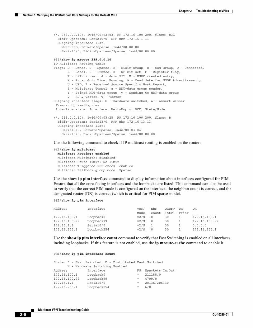
(*, 239.0.0.10), 1w4d/00:02:53, RP 172.16.100.200, flags: BCZ Bidir-Upstream: Serial0/0, RPF nbr 172.16.1.11 Outgoing interface list: MVRF RED, Forward/Sparse, 1w4d/00:00:00 Serial0/0, Bidir-Upstream/Sparse, 1w4d/00:00:00
P11#show ip mroute 239.0.0.10IP Multicast Routing TableFlags: D - Dense, S - Sparse, B - Bidir Group, s - SSM Group, C - Connected, L - Local, P - Pruned, R - RP-bit set, F - Register flag, T - SPT-bit set, J - Join SPT, M - MSDP created entry, X - Proxy Join Timer Running, A - Candidate for MSDP Advertisement, U - URD, I - Received Source Specific Host Report, Z - Multicast Tunnel, z - MDT-data group sender, Y - Joined MDT-data group, y - Sending to MDT-data group V - RD & Vector, v - VectorOutgoing interface flags: H - Hardware switched, A - Assert winner Timers: Uptime/Expires Interface state: Interface, Next-Hop or VCD, State/Mode
(*, 239.0.0.10), 1w4d/00:03:25, RP 172.16.100.200, flags: B Bidir-Upstream: Serial3/0, RPF nbr 172.16.13.13 Outgoing interface list: Serial0/0, Forward/Sparse, 1w4d/00:03:04 Serial3/0, Bidir-Upstream/Sparse, 1w4d/00:00:00
Use the following command to check if IP multicast routing is enabled on the router:
PE1#show ip multicast Multicast Routing: enabled Multicast Multipath: disabled Multicast Route limit: No limit Multicast Triggered RPF check: enabled Multicast Fallback group mode: Sparse
Use the show ip pim interface command to display information about interfaces configured for PIM. Ensure that all the core-facing interfaces and the loopbacks are listed. This command can also be used to verify that the correct PIM mode is configured on the interface, the neighbor count is correct, and the designated router (DR) is correct (which is critical for PIM sparse mode).
PE1#show ip pim interface
Address Interface Ver/ Nbr Query DR DR Mode Count Intvl Prior172.16.100.1 Loopback0 v2/S 0 30 1 172.16.100.1172.16.100.99 Loopback99 v2/S 0 30 1 172.16.100.99172.16.1.1 Serial0/0 v2/S 1 30 1 0.0.0.0172.16.255.1 Loopback254 v2/S 0 30 1 172.16.255.1
Use the show ip pim interface count command to verify that Fast Switching is enabled on all interfaces, including loopbacks. If this feature is not enabled, use the ip mroute-cache command to enable it.
PE1#show ip pim interface count
State: * - Fast Switched, D - Distributed Fast Switched H - Hardware Switching EnabledAddress Interface FS Mpackets In/Out172.16.100.1 Loopback0 * 211188/0172.16.100.99 Loopback99 * 4709/0172.16.1.1 Serial0/0 * 20136/206330172.16.255.1 Loopback254 * 6/0
2-6Multicast VPN Troubleshooting Guide
OL-10380-01

Chapter 2 Troubleshooting mVPNs Section 1: Verifying the IP Multicast Core Settings for the Default MDT
Use the show ip pim neighbor command to verify that you see PIM neighbors on the core-facing interface. Check for the B flag under Mode if you are running Bidir in the core. The following output is for PIM-SM and Bidir, respectively.
PE1#show ip pim neighbor PIM Neighbor TableNeighbor Interface Uptime/Expires Ver DRAddress Priority/Mode172.16.1.11 Serial0/0 19:28:56/00:01:38 v2 1 / P
PE1#show ip pim neighborPIM Neighbor TableNeighbor Interface Uptime/Expires Ver DRAddress Priority/Mode172.16.1.11 Serial0/0 00:08:00/00:01:38 v2 1 / B P
Use the show ip pim rp mapping command to check the RP assignment for the MDT-default multicast group range, and to verify that the source of RP learning (static or AutoRP) and the mapping are correct and consistent with rest of the network.
PE1#show ip pim rp mapping PIM Group-to-RP Mappings
Acl: 1, Static-Override RP: 172.16.100.200 (?)RPF checks
Use the show ip rpf ip_address command to display how IP multicast routing does Reverse Path Forwarding (RPF). When you troubleshoot, use it to verify that the RPF information is correct. If it is not, check the unicast routing table for the source address. Also use the ping and trace commands on the source address to verify that unicast routing works.
PE1#show ip rpf 172.16.100.200RPF information for ? (172.16.100.200) RPF interface: Serial0/0 RPF neighbor: ? (172.16.1.11) RPF route/mask: 172.16.100.200/32 RPF type: unicast (ospf 1) RPF recursion count: 0 Doing distance-preferred lookups across tables
The following example shows output of RP mapping check:
RTR#show ip pim rp mapping PIM Group-to-RP Mappings
Acl: 1, Static RP: 172.16.100.200 (?)
Show ip mroute for PIM SM with SPT Threshold 0
The following example shows output of the show ip mroute command for the default mdt address.
On the P-RP:
P-RP#show ip mroute 239.0.0.10 | begin 239(*, 239.0.0.10), 18:48:26/00:03:21, RP 172.16.100.200, flags: S Incoming interface: Null, RPF nbr 0.0.0.0 Outgoing interface list: Serial0/0, Forward/Sparse, 18:48:25/00:02:47 Serial1/0, Forward/Sparse, 18:48:26/00:03:21
2-7Multicast VPN Troubleshooting Guide
OL-10380-01

Chapter 2 Troubleshooting mVPNs Section 1: Verifying the IP Multicast Core Settings for the Default MDT
(172.16.100.1, 239.0.0.10), 18:48:25/00:03:27, flags: T Incoming interface: Serial1/0, RPF nbr 172.16.213.13 Outgoing interface list: Serial0/0, Forward/Sparse, 18:48:25/00:02:47
(172.16.100.2, 239.0.0.10), 18:48:25/00:00:54, flags: PT Incoming interface: Serial0/0, RPF nbr 172.16.212.12 Outgoing interface list: Null
Note in the above output, the OIL (outgoing interface list) is Null because the (PE2, 239.0.0.10) Tree was pruned (P flag) on the P-RP, as the source path tree was constructed directly between the source PE2 and the other PEs as leaves.
(172.16.100.3, 239.0.0.10), 18:48:26/00:03:27, flags: T Incoming interface: Serial1/0, RPF nbr 172.16.213.13 Outgoing interface list: Serial0/0, Forward/Sparse, 18:48:25/00:02:47
On a P router:
P12#show ip mroute 239.0.0.10 | begin 239(*, 239.0.0.10), 18:48:00/00:02:43, RP 172.16.100.200, flags: S Incoming interface: Serial2/0, RPF nbr 172.16.212.200 Outgoing interface list: Serial0/0, Forward/Sparse, 18:48:00/00:02:43
(172.16.100.2, 239.0.0.10), 18:48:00/00:03:24, flags: T Incoming interface: Serial0/0, RPF nbr 172.16.2.2 Outgoing interface list: Serial1/0, Forward/Sparse, 18:47:30/00:02:58 Serial3/0, Forward/Sparse, 18:48:00/00:02:44
On a PE router:
PE1#show ip mroute 239.0.0.10 | begin 239(*, 239.0.0.10), 17:20:07/stopped, RP 172.16.100.200, flags: SJCFZ Incoming interface: Serial0/0, RPF nbr 172.16.1.11 Outgoing interface list: MVRF RED, Forward/Sparse, 17:20:07/00:00:00
(172.16.100.1, 239.0.0.10), 17:20:07/00:03:26, flags: FT Incoming interface: Loopback0, RPF nbr 0.0.0.0 Outgoing interface list: Serial0/0, Forward/Sparse, 17:19:15/00:03:20
Note The above is the local (S,G) source entry on PE1 (here S= PE1), which explains why there is no Z flag.
(172.16.100.2, 239.0.0.10), 17:20:02/00:02:56, flags: JTZ Incoming interface: Serial0/0, RPF nbr 172.16.1.11 Outgoing interface list: MVRF RED, Forward/Sparse, 17:20:02/00:00:00
(172.16.100.3, 239.0.0.10), 17:19:56/00:02:48, flags: JTZ Incoming interface: Serial0/0, RPF nbr 172.16.1.11 Outgoing interface list: MVRF RED, Forward/Sparse, 17:19:56/00:00:00
2-8Multicast VPN Troubleshooting Guide
OL-10380-01

Chapter 2 Troubleshooting mVPNs Section 2: Verifying the PE-PE PIM Neighbor Relationship over the MTI
Note For a remote PE, there should not be (S,GPA) entry when SPT threshold is set to infinity; but there should be an mstate (S,GPA) entry for the local PE.
Show ip mroute for PIM Bidir
The following example shows output of the show ip mroute command for the default mdt group address:
PE1#show ip mroute 239.0.0.10 | begin 239
(*, 239.0.0.10), 00:30:00/00:02:51, RP 172.16.100.200, flags: BCZ Bidir-Upstream: Serial0/0, RPF nbr 172.16.1.11 Outgoing interface list: MVRF RED, Forward/Sparse, 00:30:00/00:00:00 Serial0/0, Bidir-Upstream/Sparse, 00:30:00/00:00:00
P-RP#show ip mroute | begin 239
(*, 239.0.0.10), 02:34:18/00:02:42, RP 172.16.100.200, flags: B Bidir-Upstream: Null, RPF nbr 0.0.0.0 Outgoing interface list: Serial1/0, Forward/Sparse, 02:34:16/00:02:30 Serial0/0, Forward/Sparse, 02:34:18/00:02:42
Using the mtrace Command
The mtrace command shows the multicast path from the source to the receiver. This command traces the path between points in the networks, which shows TTL thresholds and delay at each node. When troubleshooting, use the mtrace command to find where multicast traffic flow stops, to verify the path of multicast traffic, and to identify sub-optimal paths. In the mtrace command, when testing the default mdt, use the MTI or the RP address as source address, not the PE-P core interfaces addresses.
Refer to Using the Mtrace Tool in Troubleshooting Multicast Issues, page 3-7 for details about the mtrace command.
Section 2: Verifying the PE-PE PIM Neighbor Relationship over the MTI
This section is divided into several subsections to guide you through the various levels of checks needed on a PE to ensure a healthy interaction with the other PEs that belong to the mVPN, as described below:
• Ensure that the PE settings needed for the MTI interface are valid with respect to PIM parameters, BGP peerings, and IP address.
• Check the mstates for the default mdt in the multicast routing table.
Note that conceptually the PEs are PIM neighbors over the MTI interface because they are one hop away from each other when considering the tunnel interface. Thus, they behave as if they were all directly connected from a PIM point of view and the MTI is the interface towards a virtual shared media.
The high-level flowchart in Figure 2-3 describes how to navigate through the different subsections and should be used as the main reference when troubleshooting the MTI configuration and the PE to PE communication over the MTI.
2-9Multicast VPN Troubleshooting Guide
OL-10380-01

Chapter 2 Troubleshooting mVPNs Section 2: Verifying the PE-PE PIM Neighbor Relationship over the MTI
Consider the following assumptions for the troubleshooting in this section:
• Focus on the mVPN edge, but not the VPN customer multicast traffic.
• Focus on a specific default MDT group.
• Know the number, characteristics, and location of the mVPN PEs and their BGP next hop and BGP update-source information.
• The MPLS VPN unicast connectivity should be operating without any problems.
For each PE, ensure the following:
• The MTI tunnel interface is UP/UP and its configured parameters are the same as for the other PEs.
• The BGP and VRF settings for the default mdt are properly configured.
• The core PIM mode and settings are consistent for all PEs.
• The PE is able to establish PIM peerings with remote PEs over the MTI.
• The (*,GPA) and potential (S,GPA) are in the MRIB and their parameters are configured as intended.
Note that troubleshooting the mVPN data flow (including the core) is described under Section 4: Verifying mVPN Data Flow, page 2-80.
Gathering InformationBefore troubleshooting the default mdt settings of the edge PEs, use the following questions to gather as much information as possible about the traffic and issues of the enterprise customers. This will help to select a subset of PEs to start the troubleshooting (unless you already have selected the PEs you want to troubleshoot based on other criteria).
• Is this customer the only enterprise customer that has issues with its multicast traffic?
• Is there a specific POP (PE location) that has multicast issues?
• Which customer groups (C-groups) have multicast issues?
• Are there issues for specific customer multicast groups?
• Which customer sources (C-sources) present issues, and for which groups?
• Where are the sources, receivers, and RPs are located?
MethodologyWhen dealing with a large number of PEs, it is difficult to verify that all of the PEs see each other as PIM neighbors. It is also difficult to verify that the (S,GPA) state for each PE on the Mroute table of the remote PEs is correct.
Therefore, the methodology followed in this guide is to approach the problem incrementally:
• First, focus on checking only two PEs.
• Then, add one PE at a time to these and check the edge settings for this new subset, focusing on the latest added PE.
The concept of adding a single PE (site) is also useful for troubleshooting setups in which an mVPN service is incrementally added for a new site of a customer VPN.
2-10Multicast VPN Troubleshooting Guide
OL-10380-01
Chapter 2 Troubleshooting mVPNs Section 2: Verifying the PE-PE PIM Neighbor Relationship over the MTI
Note that the above described logic implies that, when adding a given PE to the subset, it is understood that all previously checked PEs are at this point fully operational for the mVPN. The diagrams in this section are based on this assumption.
The total number of PEs considered at a given time is noted n.
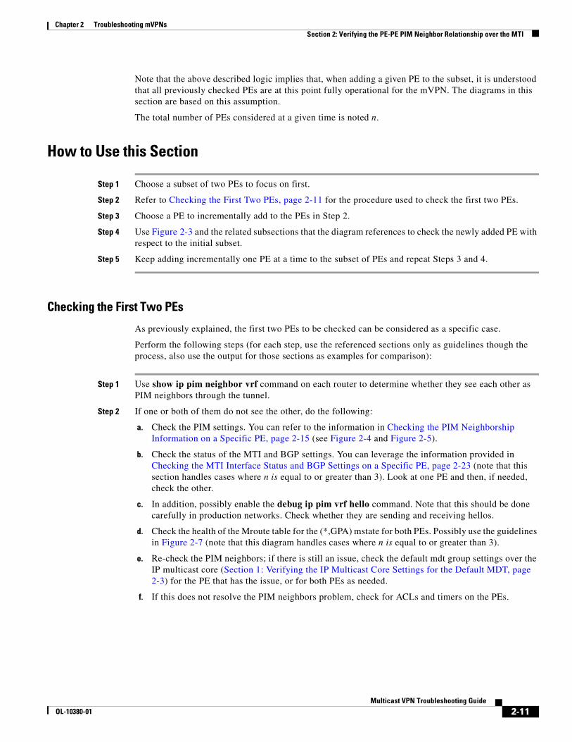
How to Use this Section
Step 1 Choose a subset of two PEs to focus on first.
Step 2 Refer to Checking the First Two PEs, page 2-11 for the procedure used to check the first two PEs.
Step 3 Choose a PE to incrementally add to the PEs in Step 2.
Step 4 Use Figure 2-3 and the related subsections that the diagram references to check the newly added PE with respect to the initial subset.
Step 5 Keep adding incrementally one PE at a time to the subset of PEs and repeat Steps 3 and 4.
Checking the First Two PEs
As previously explained, the first two PEs to be checked can be considered as a specific case.
Perform the following steps (for each step, use the referenced sections only as guidelines though the process, also use the output for those sections as examples for comparison):
Step 1 Use show ip pim neighbor vrf command on each router to determine whether they see each other as PIM neighbors through the tunnel.
Step 2 If one or both of them do not see the other, do the following:
a. Check the PIM settings. You can refer to the information in Checking the PIM Neighborship Information on a Specific PE, page 2-15 (see Figure 2-4 and Figure 2-5).
b. Check the status of the MTI and BGP settings. You can leverage the information provided in Checking the MTI Interface Status and BGP Settings on a Specific PE, page 2-23 (note that this section handles cases where n is equal to or greater than 3). Look at one PE and then, if needed, check the other.
c. In addition, possibly enable the debug ip pim vrf hello command. Note that this should be done carefully in production networks. Check whether they are sending and receiving hellos.
d. Check the health of the Mroute table for the (*,GPA) mstate for both PEs. Possibly use the guidelines in Figure 2-7 (note that this diagram handles cases where n is equal to or greater than 3).
e. Re-check the PIM neighbors; if there is still an issue, check the default mdt group settings over the IP multicast core (Section 1: Verifying the IP Multicast Core Settings for the Default MDT, page 2-3) for the PE that has the issue, or for both PEs as needed.
f. If this does not resolve the PIM neighbors problem, check for ACLs and timers on the PEs.
2-11Multicast VPN Troubleshooting Guide
OL-10380-01

Chapter 2 Troubleshooting mVPNs Section 2: Verifying the PE-PE PIM Neighbor Relationship over the MTI
g. After the PEs are both seeing each other as PIM neighbors over the MDT Tunnel, check the health of the Mroute states for the default MDT group (*,GPA) if not done previously. If applicable, also check the (S,GPA). Possibly use Checking the Mroute State Information pertaining to the Default MDTGPA on a Specific PE, page 2-33 (note that this section handles cases where n is equal to or greater than 3).
If issues remain after you have thoroughly checked all of the above, contact the Cisco TAC. It is a good practice to be ready with the output of the above to optimize the assistance from TAC.
High Level Diagram of Steps to Follow when Troubleshooting the PEs Edge Settings of an mVPN for a subset of a Number (n) of PEs
The high level diagram in Figure 2-3 and the diagrams in Figure 2-4 through Figure 2-8 focus on incrementally adding one PE to the previously checked PEs. This means that it is assumed that the first two PEs have already been checked using the guidelines in Checking the First Two PEs, page 2-11.
On this last PE added, the following checks are performed:
• Local checks pertaining to PIM neighborship settings and Mroute states.
• Check the remote PEs belonging to the subset to ensure PIM neighborship reciprocity with the last added PE.
• Check the (S,GPA) for the new PE on the remote PEs of the subset (if applicable, depending on the default mdt PIM mode).
2-12Multicast VPN Troubleshooting Guide
OL-10380-01

Chapter 2 Troubleshooting mVPNs Section 2: Verifying the PE-PE PIM Neighbor Relationship over the MTI
Figure 2-3 High-Level Diagram for Troubleshooting the PEs Edge Settings of an mVPN
I n t h i s s c e n a r i o , a s u b s e t o f N P E s w h e r e N > = 3 i s c o n s i d e r e d . T h ef o c u s i s o n t h e l a s t a d d e d P E .
( R e f e r t o N o t e 1 f o r d e s c r i p t i o n o f k e y a s s u m p t i o n s & p r e r e q u i s i t e s )
F o r t h i s P E a p p l yF i g u r e 2 - 4
A p p l y F i g u r e 2 - 7 t o c h e c k s a n i t y o f P E ’ s g lo b a l m s t a t e s f o r M D T G P A
I f a l r e a d y a p p l i e d , s k i p a n d g o t o n e x t s t e p
H o o k s i nF i g u r e 2 - 4 t o c h e c kP E ’ s M T I / B G P i n f o
M T I a n d B G P s e t t in g s a r e h e a l t h y
E d g e s e t u p f o r t h i s s p e c i f i c m V P N = c h e c k e d O KS e e N o t e 3
F o l l o w i n s t r u c t i o n s f r o m F ig u r e 2 - 1 ; g o t o n e x t r e l e v a n t s e c t i o n o r r e t u r n t o t h e s e c t i o n t h a t d i r e c t e d y o u h e r e
F o r t h i s P E a p p ly F i g u r e 2 - 5
a l l o t h e r P E s o f t h e s u b s e t s h o u l d s e e i t s P E a s a P I Mn e i g h b o r w i t h a l l a p p r o p r i a t e a t t r i b u t e s .S e e N o t e 4
S u c c e s s f u l c h e c k o fP I M N e i g h b o r s e t t i n g s
S e e N o t e 2 ; S e l e c t n e x t P E t o p e r f o r m s a m e c h e c k s a s a b o v e
a l l P E s = c h e c k e d
I s s u e s h i p m r o u t e G P A o n e a c h o f a l l p r e v i o u s l y c h e c k e d P E s .V e r i f y t h a t t h e r e i s a h e a l t h y ( S , G P A ) e n t r y f o r t h i s P E .
s e e N o t e 6S k i p t h i s c h e c k i f t h e M D T m o d e i s B i d i r
Y e s
Y e s
N o
F o r t h i s P E a p p l y“ V e r i f y i n g t h e I Pm u l t i c a s t C o r es e t t i n g s f o r t h eM D T ” ( S e c t i o n 1 )
I f t h e M D T P I M m o d e = B id i r , m o v e t o n e x t s t e p ,o t h e r w i s e a p p l y F i g u r e 2 - 8 t o P E
H o o k s t o c h e c k P E ’ s c o r e s e t t i n g s
P E ’ s M D T c o r e s e t t i n g sa r e h e a l t h y
F o r t h i s P Ea p p l y F i g u r e 2 - 7
H o o k s t o c h e c ks a n i t y o f ( * , G P A ) m s t a t e :
M r o u t e s e t t i n g s c o r r e c ta s o f “ M r o u t e C h e c k s p a r t I ”
R e f e r t o N o t e5 . C o n t a c t T A C
N o
F o r t h i s P Ea p p l y F i g u r e 2 - 6
2-13Multicast VPN Troubleshooting Guide
OL-10380-01

Chapter 2 Troubleshooting mVPNs Section 2: Verifying the PE-PE PIM Neighbor Relationship over the MTI
Notes for Figure 2-3
Note 1
N = number of PEs in the subset, also known as “PEs for which we are checking the edge settings (PIM neighbors, Mstates).” N includes the PE being checked.
Note 2
Check the chosen PE as done for the previously checked PEs. Remember that checking for the PIM neighbors’ settings and Mroute table information is a recurring process, adding one PE at a time to the initial subset, until all PEs have been checked.
Note 3
By “Edge setup for this specific mVPN = checked OK,” we mean that:
• Each PE of the subset sees all the other PEs as PIM neighbors over the MDT tunnel.
• Each PE of the subset sees all expected Mroutes in its table for the mVPN.
Note 4
• By “all other PEs of the subset,” we mean all of the (N-1) PEs that were successfully checked previously.
• Remember that we are applying this diagram in a loop mode, successively for each PE.
• Use the show ip pim vrf neighbors command on each remote PE and look for the IP address of the local PE. Verify that each PE is effectively recognized as a PIM neighbor by the current PE. Also check the different PIM neighborship parameters (use guidelines from Figure 2-4 and Figure 2-5 as needed).
Note 5
The described behavior is not normal because the previously checked set of (N-1) PEs was verified as functioning well, and as all settings for the last checked PE are OK.
Note 6
• Verify that the (S,G) entry exists in the other PEs’ global Mroute table, where S is this PE’s BGP update source address and G is the MDT address (also know as GPA).
• Ensure that the Mroute entry in the tables includes all appropriate parameters (use guidelines from Figure 2-7 as needed).
2-14Multicast VPN Troubleshooting Guide
OL-10380-01

Chapter 2 Troubleshooting mVPNs Section 2: Verifying the PE-PE PIM Neighbor Relationship over the MTI
Checking the PIM Neighborship Information on a Specific PE
This section checks the PIM neighborship between one local PE and a subset of the remote PEs of the MVPN.
The present section is the first section of the PE settings checks to be performed on an incrementally added PE. Thus the section diagrams also may link to some other checks such as checks on the MTI and BGP settings (when needed to ensure its health in relation to the PE edge settings for the default mdt).
Ideally, if all local PE parameters had been well configured, the local PE should see all the remote mVPN PEs of the subset as PIM neighbors through the MDT tunnel.
Note Remember that we do incremental checks, thus when checking PIM neighborship on the local PE, only the subset of remote PEs that have previously been checked using this section (Figure 2-4 and Figure 2-5) should be considered, and not all the PEs of the MVPN (this comment is meant to explain references to expected neighbors).
Note Remember that you are looking at the PIM neighbor peerings from the view of the specific PE being examined. This PE is the new PE incrementally added to the subset. When needed, the flowchart might briefly ask the troubleshooter to log on to other remote PEs to enter some show commands, which does not mean that the troubleshooter should check every parameter on these remote PEs (we assume that the remote PEs of the subset have already been checked).
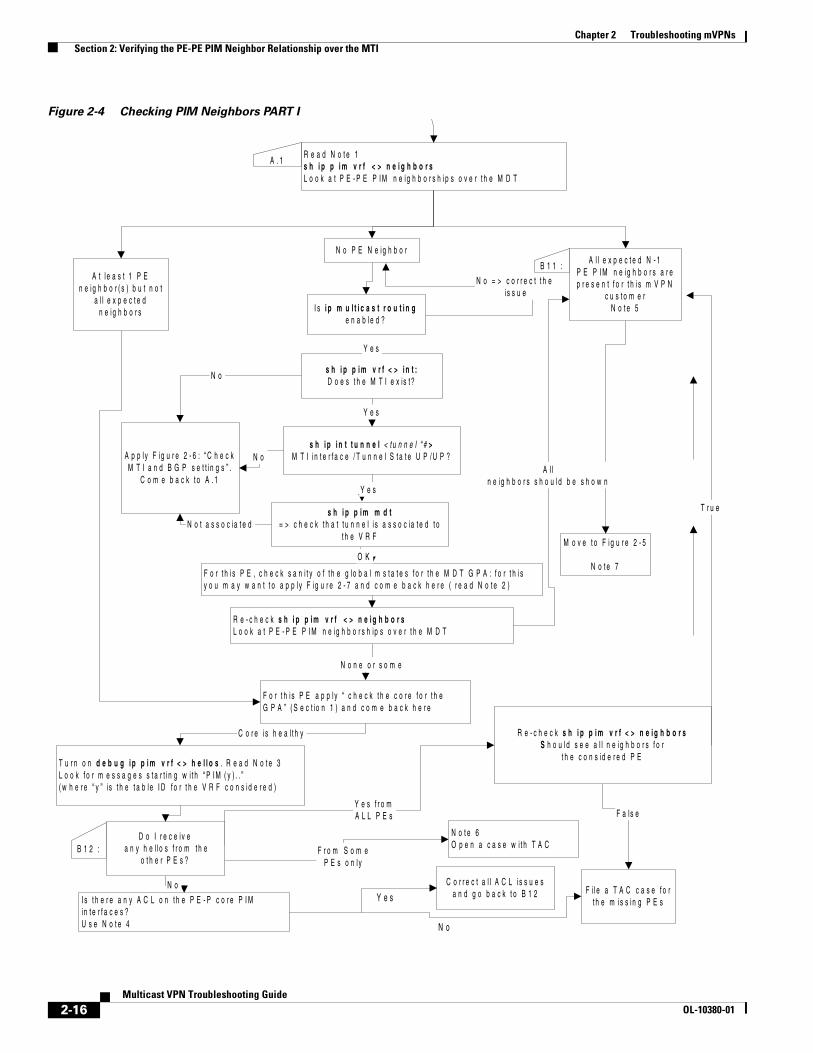
Figure 2-4 and Figure 2-5 show how to troubleshoot PIM neighborship on a given PE newly added to a subset of PEs (that have previously been checked). Note that Figure 2-4 indicates when to use Figure 2-5.
2-15Multicast VPN Troubleshooting Guide
OL-10380-01
Chapter 2 Troubleshooting mVPNs Section 2: Verifying the PE-PE PIM Neighbor Relationship over the MTI
Figure 2-4 Checking PIM Neighbors PART I
T r u e
R e a d N o t e 1s h i p p i m v r f < > n e i g h b o r sL o o k a t P E - P E P I M n e i g h b o r s h i p s o v e r t h e M D T
s h i p i n t t u n n e l < t u n n e l “ # >M T I i n t e r f a c e / T u n n e l S t a t e U P / U P ?A p p l y F i g u r e 2 - 6 : “ C h e c k
M T I a n d B G P s e t t i n g s ” .C o m e b a c k t o A . 1
s h i p p i m v r f < > i n t :D o e s t h e M T I e x is t ?
T u r n o n d e b u g i p p i m v r f < > h e l l o s . R e a d N o t e 3L o o k f o r m e s s a g e s s t a r t i n g w i t h “ P I M ( y ) . . ”( w h e r e “ y ” i s t h e t a b l e I D f o r t h e V R F c o n s i d e r e d )
N o
Y e s
I s t h e r e a n y A C L o n t h e P E - P c o r e P I Mi n t e r f a c e s ?U s e N o t e 4
N o
Y e s f r o mA L L P E s
Y e s
N o
F i l e a T A C c a s e f o rt h e m is s i n g P E s
F a ls e
C o r r e c t a l l A C L i s s u e sa n d g o b a c k t o B 1 2
Y e s
N o = > c o r r e c t t h e i s s u e
M o v e t o F i g u r e 2 - 5
N o t e 7
N o n e o r s o m e
B 1 1 :
F o r t h i s P E , c h e c k s a n i t y o f t h e g l o b a l m s t a t e s f o r t h e M D T G P A : f o r t h i sy o u m a y w a n t t o a p p l y F ig u r e 2 - 7 a n d c o m e b a c k h e r e ( r e a d N o t e 2 )
R e - c h e c k s h i p p i m v r f < > n e i g h b o r sL o o k a t P E - P E P I M n e i g h b o r s h ip s o v e r t h e M D T
A l ln e i g h b o r s s h o u l d b e s h o w n
F o r t h i s P E a p p l y “ c h e c k t h e c o r e f o r t h eG P A ” ( S e c t i o n 1 ) a n d c o m e b a c k h e r e
C o r e i s h e a l t h y
B 1 2 : F r o m S o m eP E s o n l y
N o t e 6O p e n a c a s e w i t h T A C
O K
N o t a s s o c i a t e d
A . 1
s h i p p i m m d t= > c h e c k t h a t t u n n e l i s a s s o c ia t e d t o
t h e V R F
R e - c h e c k s h i p p i m v r f < > n e i g h b o r sS h o u l d s e e a l l n e i g h b o r s f o r
t h e c o n s id e r e d P E
D o I r e c e i v e a n y h e l l o s f r o m t h e
o t h e r P E s ?
A l l e x p e c t e d N - 1P E P I M n e i g h b o r s a r ep r e s e n t f o r t h i s m V P N
c u s t o m e rN o t e 5
A t l e a s t 1 P En e i g h b o r ( s ) b u t n o t
a l l e x p e c t e dn e i g h b o r s
N o P E N e i g h b o r
I s i p m u l t i c a s t r o u t i n ge n a b l e d ?
Y e s
N o
2-16Multicast VPN Troubleshooting Guide
OL-10380-01

Chapter 2 Troubleshooting mVPNs Section 2: Verifying the PE-PE PIM Neighbor Relationship over the MTI
Notes for Figure 2-4
Note 1
• For this section, remember that we consider only the subset of N-1 remote PEs that have previously been checked and we are adding one PE (one being checked currently) to the subset. (we might refer to expected neighbors or considered PEs for the subset of PEs previously checked).
• Remember N>= 3.
Note 2
In Section 1, there are some checks made on the Core Multicast setup for the MDT group address as well.
Note 3
Don’t forget to apply the term mon command if you are on a VTY line. Also, use the show logging command, being careful to not bring the router down by using a full debug ip pim debug command applied on the console.
Note 4
• Use the show access-list command and look at the hits on the ACLs, remembering that traffic is encapsulated in GRE.
• Consider ACLs affecting GRE traffic and the MDT GPA address.
Note 5
We are considering N-1 neighbors (because we apply the show command on the last PE added to form a subset of N PEs total).
Note 6
Because we previously successfully checked the subset of remote PEs, the local MTI, and local core settings for the MDT, this is not normal.
Note 7
Refer to Figure 2-5 for the second set of checks to be performed on the PIM neighbors for the MTI settings.
2-17Multicast VPN Troubleshooting Guide
OL-10380-01

Chapter 2 Troubleshooting mVPNs Section 2: Verifying the PE-PE PIM Neighbor Relationship over the MTI
Figure 2-5 Checking PIM Neighbors PART II
C h e c k t h e B G P c o n f i g u r a t i o n o n t h i s P E :1 . C h e c k t h a t f o r e a c h P E n e i g h b o r , P I M I P a d d r e s s a n d B G P n e i g h b o r a d d r e s s a r e t h e s a m e
s h i p p im v r f < > n e i g h b o r ss h i p p im m d t b g p
S e e N o t e 2
2 . C h e c k t h a t t h e P I M n e ig h b o r I P a d d r e s s o f t h e l o c a l P E , v i e w e d b y e a c h r e m o t e P E , is t h e s a m e a st h e l o c a l ly c o n f i g u r e d u p d a t e - s o u r c e u s e d f o r B G P p e e r i n g w i t h e a c h r e m o t e P E
S e e N o t e 2
M a k e a p p r o p r i a t e c o r r e c t io n s o n t h e l o c a l P E[ f o r e a c h n e i g h b o r B G P s t a t e m e n t u n d e r V P N v 4 a d d r e s s f a m i l y ]S e e N o t e 3 ; c o n t a c t T A C i f y o u s t i l l s e e i s s u e s
O K
N o
N o t e 5P r o c e e d t o t h e n e x t s e c t io na c c o r d in g t o t h e h i g h e r - le v e ld i a g r a m
Y e s
O K
Y e s
C h e c k t h a t P E i s s e n d i n g H e l l o s o u t o n t h eM D TI f n o t , g a t h e r o u t p u t a n d o p e n a T A C c a s e .S e e N o t e 4
S T A R T
A s s u m p t i o n :A l l c o n s id e r e d ( N - 1 ) P E P I M n e i g h b o r s a r e p r e s e n t f o r t h i s m V P N c u s t o m e rS e e N o t e 1
R e c h e c k
D o a s a n i t y c h e c k o n t h e l o c a lP E s B i d i r s e t t in g s .
S e e N o t e 7 . C o r r e c t a s n e e d e d
R e a d N o t e 6 . O p e n a T A C c a s e
I s s u e s h i p p i m v r f < >n e i g h b o r s :
D o y o u s e e t h e B p r o p r i e t ie sf la g f o r a l l P E P I M n e i g h b o r s ?
N o t t r u e f o r a l l P E s
I s t h eM D T m o d e
B i d i r ?
2-18Multicast VPN Troubleshooting Guide
OL-10380-01

Chapter 2 Troubleshooting mVPNs Section 2: Verifying the PE-PE PIM Neighbor Relationship over the MTI
Notes for Figure 2-5
Note 1
• Figure 2-4 was previously checked for this PE.
• Note that the terminology is the same as defined in Figure 2-5 for checking the PIM neighbors - part I.
Note 2
• Enter the show ip pim vrf neighbors command and watch for the IP address of the neighbors. Enter the show ip pim mdt bgp command and watch for the next hop information in that output on the remote PEs.
The two IP addresses representing the local PE in this output should be the same (repeat this on each of the remote PEs).
• Update the source IP address, or the BGP next hop if a next hop was configured for this mVRF.
Note 3
• Keep in mind that BGP peering address changes might restart the BGP peerings.
• Ensure that, on each remote PE, for the PIM neighbor the information is synchronized with the latest BGP update source and BGP next hop address.
Note 4
• You can check this using the debug ip pim vrf hellos command.
• This should be the case because the MTI interface and tunnel state is UP/UP and we already checked timers.
Note 5
The PE is healthy with respect to the PIM neighbor settings over the MTI. A higher level diagram would be Figure 2-3. It could be, however, that other sections of this document leverage Figure 2-5. In that case, as you have just successfully completed the checks in this flowchart, return to the figure that referred you to this one.
Note 6
Remember that we have previously checked all (N-1) PEs of the subset.
Note 7
• Check for the RP and the GPA BIDIR settings (check for Bidir globally enabled, RP is bidir enabled) using the following commands:
show ip pim rp mapping [in-use]
show ip mroute
• When finished, skip to the next step.
Sample Output to Compare your Setup while Leveraging Figures 4 and 5
Use the following output as a reference when using the flowchart diagram. Compare your output to the sample output taken on an appropriate mVPN Bidir and PIM SM setup.
The following shows the output of show ip pim neighbors vrf RED command on a correct setup with Bidir as PIM mode in the core for the default MDT, and for PIM SM with SPT 0:
2-19Multicast VPN Troubleshooting Guide
OL-10380-01

Chapter 2 Troubleshooting mVPNs Section 2: Verifying the PE-PE PIM Neighbor Relationship over the MTI
PE1# show ip pim vrf RED neighbor PIM Neighbor TableNeighbor Interface Uptime/Expires Ver DRAddress Priority/Mode192.168.11.2 Serial1/0 00:08:11/00:01:27 v2 1 / P192.168.112.2 Serial2/0 00:08:11/00:01:27 v2 1 / P172.16.100.3 Tunnel0 00:07:09/00:01:30 v2 1 / DR B P172.16.100.2 Tunnel0 00:07:09/00:01:30 v2 1 / B P
PE1#show ip pim vrf RED neighborPIM Neighbor TableNeighbor Interface Uptime/Expires Ver DRAddress Priority/Mode192.168.11.2 Serial1/0 2w2d/00:01:40 v2 1 / P192.168.112.2 Serial2/0 2w2d/00:01:41 v2 1 / P172.16.100.2 Tunnel0 2w2d/00:01:21 v2 1 / P172.16.100.3 Tunnel0 2w2d/00:01:43 v2 1 / DR P
The following output of the show ip mroute GPA summary command is taken for Bidir and PIM SM with SPT 0 respectively. Note that in the Bidir case, there is a (*,GPA) state but no (S,GPA) states.
PE1#show ip mroute 239.0.0.10 summary IP Multicast Routing TableFlags: D - Dense, S - Sparse, B - Bidir Group, s - SSM Group, C - Connected, L - Local, P - Pruned, R - RP-bit set, F - Register flag, T - SPT-bit set, J - Join SPT, M - MSDP created entry, X - Proxy Join Timer Running, A - Candidate for MSDP Advertisement, U - URD, I - Received Source Specific Host Report, Z - Multicast Tunnel, z - MDT-data group sender, Y - Joined MDT-data group, y - Sending to MDT-data group V - RD & Vector, v - VectorOutgoing interface flags: H - Hardware switched, A - Assert winner Timers: Uptime/Expires Interface state: Interface, Next-Hop or VCD, State/Mode
(*, 239.0.0.10), 00:31:03/00:02:59, RP 172.16.100.200, OIF count: 2, flags: BCZ
Note that in the PIM SM case, the (S,GPA) corresponding to S =Local PE does not present a Z flag; this flag is used on the MRIB to indicate a need to decapsulate an incoming packet.
PE1#show ip mroute 239.0.0.10 summary IP Multicast Routing TableFlags: D - Dense, S - Sparse, B - Bidir Group, s - SSM Group, C - Connected, L - Local, P - Pruned, R - RP-bit set, F - Register flag, T - SPT-bit set, J - Join SPT, M - MSDP created entry, X - Proxy Join Timer Running, A - Candidate for MSDP Advertisement, U - URD, I - Received Source Specific Host Report, Z - Multicast Tunnel, z - MDT-data group sender, Y - Joined MDT-data group, y - Sending to MDT-data group V - RD & Vector, v - VectorOutgoing interface flags: H - Hardware switched, A - Assert winner Timers: Uptime/Expires Interface state: Interface, Next-Hop or VCD, State/Mode
(*, 239.0.0.10), 2w2d/stopped, RP 172.16.100.200, OIF count: 1, flags: SJCFZ (172.16.100.1, 239.0.0.10), 2w2d/00:03:29, OIF count: 1, flags: FT (172.16.100.2, 239.0.0.10), 2w2d/00:02:47, OIF count: 1, flags: JTZ (172.16.100.3, 239.0.0.10), 2w2d/00:02:55, OIF count: 1, flags: JTZ
2-20Multicast VPN Troubleshooting Guide
OL-10380-01

Chapter 2 Troubleshooting mVPNs Section 2: Verifying the PE-PE PIM Neighbor Relationship over the MTI
Following is a sample of the syslog messages that should be seen in the buffer (on the console) sent to a syslog server at startup of a PE if the configuration for the mVPN has been properly added, or when the appropriate commands are added on a PE:
PE1#*Oct 4 01:31:58.151: %LINEPROTO-5-UPDOWN: Line protocol on Interface Tunnel0, changed state to up*Oct 4 01:31:58.151: %LINEPROTO-5-UPDOWN: Line protocol on Interface Tunnel0, changed state to up*Oct 4 01:31:58.299: %PIM-5-NBRCHG: neighbor 172.16.100.2 UP on interface Tunnel0 (vrf RED) *Oct 4 01:31:58.299: %PIM-5-DRCHG: DR change from neighbor 0.0.0.0 to 172.16.100.2 on interface Tunnel0 (vrf RED)*Oct 4 01:31:58.355: %PIM-5-NBRCHG: neighbor 172.16.100.3 UP on interface Tunnel0 (vrf RED) *Oct 4 01:31:58.355: %PIM-5-DRCHG: DR change from neighbor 172.16.100.2 to 172.16.100.3 on interface Tunnel0 (vrf RED)
Following is a sample output with debugs on for IP PIM hellos in the VRF RED context. Use caution when turning on debugs so as not to bring the device down. Note that the value x in the output in such lines as PIM(x) identifies the global table (0) or the VRF table ID (here table ID equals 1 for VRF RED).
PE1#show debugIP multicast: PIM HELLO debugging is on in vrf REDPE1#*Oct 4 02:07:51.779: PIM(0): Send periodic v2 Hello on Serial0/0*Oct 4 02:07:52.587: PIM(0): Received v2 hello on Serial0/0 from 172.16.1.11*Oct 4 02:07:55.035: PIM(1): Send periodic v2 Hello on Tunnel0*Oct 4 02:07:55.095: PIM(0): Send periodic v2 Hello on Loopback0*Oct 4 02:07:55.127: PIM(0): Received v2 hello on Loopback0 from 172.16.100.1*Oct 4 02:07:55.375: PIM(1): Received v2 hello on Tunnel0 from 172.16.100.3*Oct 4 02:07:55.559: PIM(1): Received v2 hello on Serial1/0 from 192.168.11.2*Oct 4 02:07:57.259: PIM(1): Send periodic v2 Hello on Serial2/0*Oct 4 02:07:57.691: PIM(1): Received v2 hello on Serial2/0 from 192.168.112.2*Oct 4 02:07:59.683: PIM(1): Received v2 hello on Tunnel0 from 172.16.100.2*Oct 4 02:08:02.051: PIM(1): Send periodic v2 Hello on Serial1/0
Use the show ip pim [vrf RED] interface count command successively to observe the increasing number of packets in or out for a given interface; that is, for the MTI/tunnel interface when using the VRF option. Note that in the absence of customer multicast traffic, the hellos sent over the MTI travel on the default mdt and as such, increment the counters for the tunnel/MTI interface.
Note also that such output allows you to check whether the Fast Switching capability is turned on for a specific interface.
PE1#show ip pim interface count
State: * - Fast Switched, D - Distributed Fast Switched H - Hardware Switching EnabledAddress Interface FS Mpackets In/Out172.16.100.1 Loopback0 * 141/0172.16.1.1 Serial0/0 * 234/134
Note It is normal for the number of Outgoing packets to be null on the Loopback0 interface.
PE1#sh ip pim interface count
State: * - Fast Switched, D - Distributed Fast Switched
2-21Multicast VPN Troubleshooting Guide
OL-10380-01
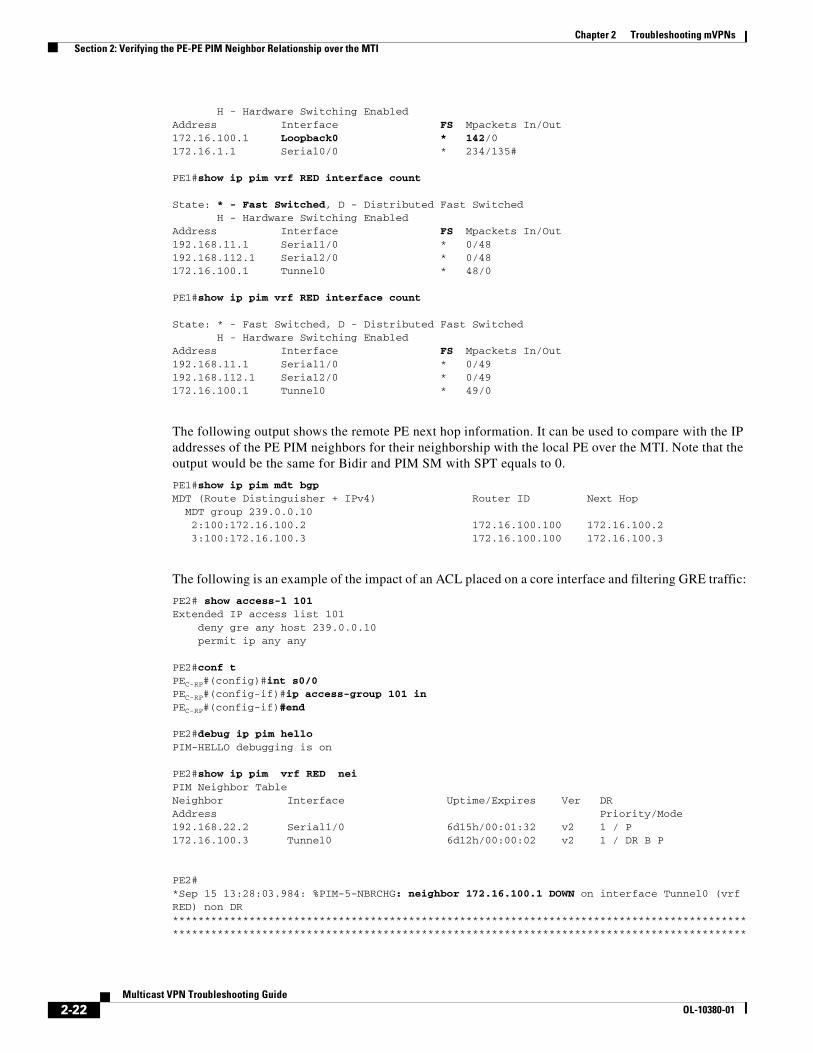
Chapter 2 Troubleshooting mVPNs Section 2: Verifying the PE-PE PIM Neighbor Relationship over the MTI
H - Hardware Switching EnabledAddress Interface FS Mpackets In/Out172.16.100.1 Loopback0 * 142/0172.16.1.1 Serial0/0 * 234/135#
PE1#show ip pim vrf RED interface count
State: * - Fast Switched, D - Distributed Fast Switched H - Hardware Switching EnabledAddress Interface FS Mpackets In/Out192.168.11.1 Serial1/0 * 0/48192.168.112.1 Serial2/0 * 0/48172.16.100.1 Tunnel0 * 48/0
PE1#show ip pim vrf RED interface count
State: * - Fast Switched, D - Distributed Fast Switched H - Hardware Switching EnabledAddress Interface FS Mpackets In/Out192.168.11.1 Serial1/0 * 0/49192.168.112.1 Serial2/0 * 0/49172.16.100.1 Tunnel0 * 49/0
The following output shows the remote PE next hop information. It can be used to compare with the IP addresses of the PE PIM neighbors for their neighborship with the local PE over the MTI. Note that the output would be the same for Bidir and PIM SM with SPT equals to 0.
PE1#show ip pim mdt bgp MDT (Route Distinguisher + IPv4) Router ID Next Hop MDT group 239.0.0.10 2:100:172.16.100.2 172.16.100.100 172.16.100.2 3:100:172.16.100.3 172.16.100.100 172.16.100.3
The following is an example of the impact of an ACL placed on a core interface and filtering GRE traffic:
PE2# show access-l 101Extended IP access list 101 deny gre any host 239.0.0.10 permit ip any any
PE2#conf tPEC-RP#(config)#int s0/0 PEC-RP#(config-if)#ip access-group 101 in PEC-RP#(config-if)#end
PE2#debug ip pim hello PIM-HELLO debugging is on
PE2#show ip pim vrf RED neiPIM Neighbor TableNeighbor Interface Uptime/Expires Ver DRAddress Priority/Mode192.168.22.2 Serial1/0 6d15h/00:01:32 v2 1 / P172.16.100.3 Tunnel0 6d12h/00:00:02 v2 1 / DR B P
PE2#*Sep 15 13:28:03.984: %PIM-5-NBRCHG: neighbor 172.16.100.1 DOWN on interface Tunnel0 (vrf RED) non DR************************************************************************************************************************************************************************************
2-22Multicast VPN Troubleshooting Guide
OL-10380-01
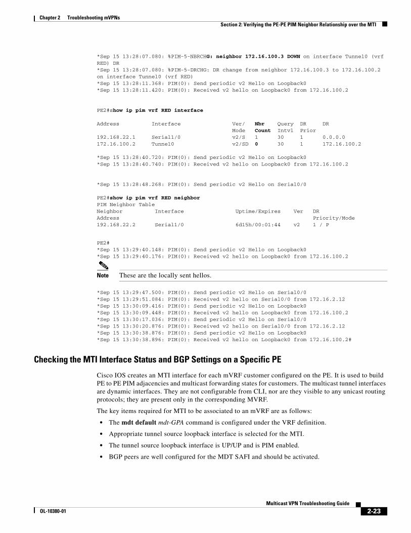
Chapter 2 Troubleshooting mVPNs Section 2: Verifying the PE-PE PIM Neighbor Relationship over the MTI
*Sep 15 13:28:07.080: %PIM-5-NBRCHG: neighbor 172.16.100.3 DOWN on interface Tunnel0 (vrf RED) DR*Sep 15 13:28:07.080: %PIM-5-DRCHG: DR change from neighbor 172.16.100.3 to 172.16.100.2 on interface Tunnel0 (vrf RED)*Sep 15 13:28:11.368: PIM(0): Send periodic v2 Hello on Loopback0*Sep 15 13:28:11.420: PIM(0): Received v2 hello on Loopback0 from 172.16.100.2
PE2#show ip pim vrf RED interface
Address Interface Ver/ Nbr Query DR DR Mode Count Intvl Prior192.168.22.1 Serial1/0 v2/S 1 30 1 0.0.0.0172.16.100.2 Tunnel0 v2/SD 0 30 1 172.16.100.2
*Sep 15 13:28:40.720: PIM(0): Send periodic v2 Hello on Loopback0*Sep 15 13:28:40.740: PIM(0): Received v2 hello on Loopback0 from 172.16.100.2
*Sep 15 13:28:48.268: PIM(0): Send periodic v2 Hello on Serial0/0
PE2#show ip pim vrf RED neighborPIM Neighbor TableNeighbor Interface Uptime/Expires Ver DRAddress Priority/Mode192.168.22.2 Serial1/0 6d15h/00:01:44 v2 1 / P
PE2#*Sep 15 13:29:40.148: PIM(0): Send periodic v2 Hello on Loopback0*Sep 15 13:29:40.176: PIM(0): Received v2 hello on Loopback0 from 172.16.100.2
Note These are the locally sent hellos.
*Sep 15 13:29:47.500: PIM(0): Send periodic v2 Hello on Serial0/0*Sep 15 13:29:51.084: PIM(0): Received v2 hello on Serial0/0 from 172.16.2.12*Sep 15 13:30:09.416: PIM(0): Send periodic v2 Hello on Loopback0*Sep 15 13:30:09.448: PIM(0): Received v2 hello on Loopback0 from 172.16.100.2*Sep 15 13:30:17.036: PIM(0): Send periodic v2 Hello on Serial0/0*Sep 15 13:30:20.876: PIM(0): Received v2 hello on Serial0/0 from 172.16.2.12*Sep 15 13:30:38.876: PIM(0): Send periodic v2 Hello on Loopback0*Sep 15 13:30:38.896: PIM(0): Received v2 hello on Loopback0 from 172.16.100.2#
Checking the MTI Interface Status and BGP Settings on a Specific PE
Cisco IOS creates an MTI interface for each mVRF customer configured on the PE. It is used to build PE to PE PIM adjacencies and multicast forwarding states for customers. The multicast tunnel interfaces are dynamic interfaces. They are not configurable from CLI, nor are they visible to any unicast routing protocols; they are present only in the corresponding MVRF.
The key items required for MTI to be associated to an mVRF are as follows:
• The mdt default mdt-GPA command is configured under the VRF definition.
• Appropriate tunnel source loopback interface is selected for the MTI.
• The tunnel source loopback interface is UP/UP and is PIM enabled.
• BGP peers are well configured for the MDT SAFI and should be activated.
2-23Multicast VPN Troubleshooting Guide
OL-10380-01

Chapter 2 Troubleshooting mVPNs Section 2: Verifying the PE-PE PIM Neighbor Relationship over the MTI
The MTI interface has the following characteristics:
If the bgp-next hop interface command is configured in the VRF definition, then use that interface as the tunnel source interface for that VRF.
If the neighbor ip-address update-source interface command exists for a peer, the interface specified is used as the tunnel source. Here is the order of peers from which the update-source is determined:
1. The ibgp neighbor ip address activate (numerically lowest IP address) command configured in the address-family IPv4 MDT (even if the peer is not up).
2. The ibgp neighbor ip address activate (numerically lowest IP address) configured in the address-family IPv4 vpnv4 (even if the peer is not up).
3. The eBGP neighbor ip address (numerically lowest ip-address) command configured in the address-family IPv4 MDT (even if the peer is not up).
The flowchart in Figure 2-6 helps isolate MTI-related issues.
Tunnel source loopback interface Assigned by BGP for each mVRF. Check “How does MTI picks the tunnel source interface?” for details
MTI tunnel destination IP default mdt group address configured by the operator
MTI IP address unnumbered to BGP-selected Tunnel source interface
MTI encapsulation GRE
2-24Multicast VPN Troubleshooting Guide
OL-10380-01
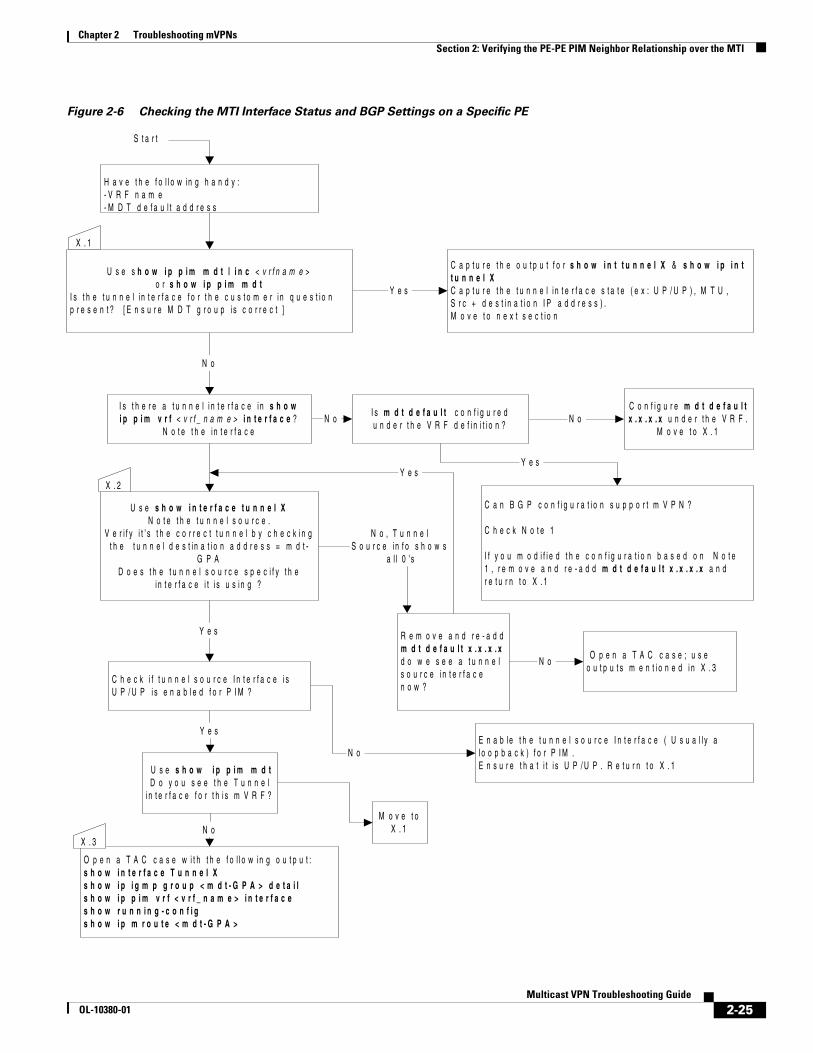
Chapter 2 Troubleshooting mVPNs Section 2: Verifying the PE-PE PIM Neighbor Relationship over the MTI
Figure 2-6 Checking the MTI Interface Status and BGP Settings on a Specific PE
S t a r t
Y e s
N o
N o N o
C a p t u r e t h e o u t p u t f o r s h o w i n t t u n n e l X & s h o w i p i n tt u n n e l XC a p t u r e t h e t u n n e l i n t e r f a c e s t a t e ( e x : U P / U P ) , M T U ,S r c + d e s t i n a t i o n I P a d d r e s s ) .M o v e t o n e x t s e c t i o n
U s e s h o w i p p i m m d t | i n c < v r f n a m e >o r s h o w i p p i m m d t
I s t h e t u n n e l i n t e r f a c e f o r t h e c u s t o m e r i n q u e s t i o np r e s e n t ? [ E n s u r e M D T g r o u p i s c o r r e c t ]
I s t h e r e a t u n n e l i n t e r f a c e i n s h o wi p p i m v r f < v r f _ n a m e > i n t e r f a c e ?
N o t e t h e i n t e r f a c e
I s m d t d e f a u l t c o n f i g u r e du n d e r t h e V R F d e f i n i t i o n ?
X . 1
C o n f i g u r e m d t d e f a u l tx . x . x . x u n d e r t h e V R F .
M o v e t o X . 1
U s e s h o w i n t e r f a c e t u n n e l XN o t e t h e t u n n e l s o u r c e .
V e r i f y i t ’ s t h e c o r r e c t t u n n e l b y c h e c k i n gt h e t u n n e l d e s t i n a t i o n a d d r e s s = m d t -
G P AD o e s t h e t u n n e l s o u r c e s p e c i f y t h e
i n t e r f a c e i t i s u s i n g ?
R e m o v e a n d r e - a d dm d t d e f a u l t x . x . x . xd o w e s e e a t u n n e ls o u r c e i n t e r f a c en o w ?
N o , T u n n e lS o u r c e i n f o s h o w s
a l l 0 ' s
C a n B G P c o n f i g u r a t i o n s u p p o r t m V P N ?
C h e c k N o t e 1
I f y o u m o d i f i e d t h e c o n f i g u r a t i o n b a s e d o n N o t e1 , r e m o v e a n d r e - a d d m d t d e f a u l t x . x . x . x a n dr e t u r n t o X . 1
Y e s
X . 2
C h e c k i f t u n n e l s o u r c e I n t e r f a c e i sU P / U P i s e n a b l e d f o r P I M ?
E n a b l e t h e t u n n e l s o u r c e I n t e r f a c e ( U s u a l l y al o o p b a c k ) f o r P I M .E n s u r e t h a t i t i s U P / U P . R e t u r n t o X . 1
Y e s
N o
Y e s
O p e n a T A C c a s e w i t h t h e f o l l o w i n g o u t p u t :s h o w i n t e r f a c e T u n n e l Xs h o w i p i g m p g r o u p < m d t - G P A > d e t a i ls h o w i p p i m v r f < v r f _ n a m e > i n t e r f a c es h o w r u n n i n g - c o n f i gs h o w i p m r o u t e < m d t - G P A >
U s e s h o w i p p i m m d tD o y o u s e e t h e T u n n e l
i n t e r f a c e f o r t h i s m V R F ?
N oX . 3
O p e n a T A C c a s e ; u s eo u t p u t s m e n t i o n e d i n X . 3
Y e s
N o
M o v e t oX . 1
H a v e t h e f o l l o w i n g h a n d y :- V R F n a m e- M D T d e f a u l t a d d r e s s
2-25Multicast VPN Troubleshooting Guide
OL-10380-01

Chapter 2 Troubleshooting mVPNs Section 2: Verifying the PE-PE PIM Neighbor Relationship over the MTI
Notes for Figure 2-6
Note 1
• We need to have neighbor ip_addr activate and neighbor ip_addr send community both under the vpnv4 AFI and neighbor ip_addr activate under MDT SAFI.
• Remember that if the PE is running an IOS later than 12.0(29)S that supports MDT SAFI, then it is essential to have the same neighbor and update source parameters in the vpnv4 configurations and in the MDT SAFI for the mVPN tunnel to come up.
• Ensure that you configure the MDT SAFI in BGP (even though we are using Intra AS mVPN). Refer to
http://www.cisco.com/en/US/products/sw/iosswrel/ps1829/products_feature_guide09186a00802a5bd9.html
Sample Output for Figure 6
The show ip pim mdt command is used to verify that the MTI is mapped to the correct mVRF.
The show ip igmp group mdt-GPA detail can be used to check if the local PE is the leaf and root for the default mdt GPA.
The show interface tunnel X can be used to check the status, tunnel source loopback, and tunnel destination for the MTI.
Note One of the most common issues encountered when troubleshooting mVPN problems is that the loopback interface that gives its properties to the MTI is not enabled for PIM.
Following is the output from a router for which the MTI and BGP are correctly configured:
PE1#show ip pim mdt MDT Group Interface Source VRF* 239.0.0.10 Tunnel16 Loopback0 RED
In the above output, we can see that the Tunnel interface exists, has an IP address (unnumbered from Loopback0), and was associated to the vrf RED.
PE1#show int tunnel 16Tunnel16 is up, line protocol is up Hardware is Tunnel Interface is unnumbered. Using address of Loopback0 (172.16.100.1) MTU 1514 bytes, BW 9 Kbit, DLY 500000 usec, rely 255/255, load 1/255 Encapsulation TUNNEL, loopback not set Keepalive not set Tunnel source 172.16.100.1 (Loopback0), destination 239.0.0.10 Tunnel protocol/transport GRE/IP Multicast, sequencing disabled Tunnel TTL 255 Key disabled Checksumming of packets disabled, fast tunneling enabled Last input 00:00:06, output 00:00:01, output hang never Last clearing of "show interface" counters never Input queue: 0/75/0/0 (size/max/drops/flushes); Total output drops: 0 Queueing strategy: fifo Output queue: 0/0 (size/max) 5 minute input rate 8000 bits/sec, 1 packets/sec 5 minute output rate 0 bits/sec, 0 packets/sec 4918 packets input, 4420606 bytes, 0 no buffer
2-26Multicast VPN Troubleshooting Guide
OL-10380-01
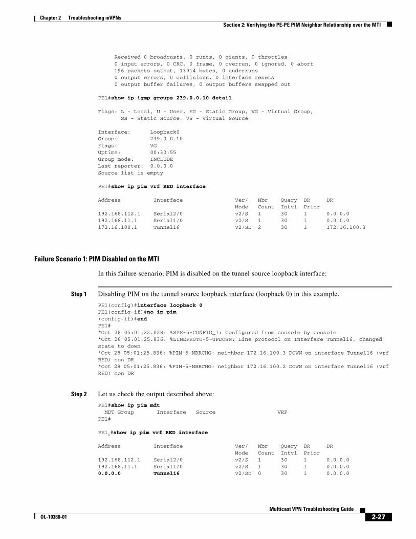
Chapter 2 Troubleshooting mVPNs Section 2: Verifying the PE-PE PIM Neighbor Relationship over the MTI
Received 0 broadcasts, 0 runts, 0 giants, 0 throttles 0 input errors, 0 CRC, 0 frame, 0 overrun, 0 ignored, 0 abort 196 packets output, 13914 bytes, 0 underruns 0 output errors, 0 collisions, 0 interface resets 0 output buffer failures, 0 output buffers swapped out
PE1#show ip igmp groups 239.0.0.10 detail
Flags: L - Local, U - User, SG - Static Group, VG - Virtual Group, SS - Static Source, VS - Virtual Source
Interface: Loopback0Group: 239.0.0.10Flags: VG Uptime: 00:30:55Group mode: INCLUDELast reporter: 0.0.0.0Source list is empty
PE1#show ip pim vrf RED interface
Address Interface Ver/ Nbr Query DR DR Mode Count Intvl Prior192.168.112.1 Serial2/0 v2/S 1 30 1 0.0.0.0192.168.11.1 Serial1/0 v2/S 1 30 1 0.0.0.0172.16.100.1 Tunnel16 v2/SD 2 30 1 172.16.100.3
Failure Scenario 1: PIM Disabled on the MTI
In this failure scenario, PIM is disabled on the tunnel source loopback interface:
Step 1 Disabling PIM on the tunnel source loopback interface (loopback 0) in this example.
PE1(config)#interface loopback 0PE1(config-if)#no ip pim(config-if)#endPE1#*Oct 28 05:01:22.028: %SYS-5-CONFIG_I: Configured from console by console*Oct 28 05:01:25.836: %LINEPROTO-5-UPDOWN: Line protocol on Interface Tunnel16, changed state to down*Oct 28 05:01:25.836: %PIM-5-NBRCHG: neighbor 172.16.100.3 DOWN on interface Tunnel16 (vrf RED) non DR*Oct 28 05:01:25.836: %PIM-5-NBRCHG: neighbor 172.16.100.2 DOWN on interface Tunnel16 (vrf RED) non DR
Step 2 Let us check the output described above:
PE1#show ip pim mdt MDT Group Interface Source VRFPE1#
PE1c#show ip pim vrf RED interface
Address Interface Ver/ Nbr Query DR DR Mode Count Intvl Prior192.168.112.1 Serial2/0 v2/S 1 30 1 0.0.0.0192.168.11.1 Serial1/0 v2/S 1 30 1 0.0.0.00.0.0.0 Tunnel16 v2/SD 0 30 1 0.0.0.0
2-27Multicast VPN Troubleshooting Guide
OL-10380-01
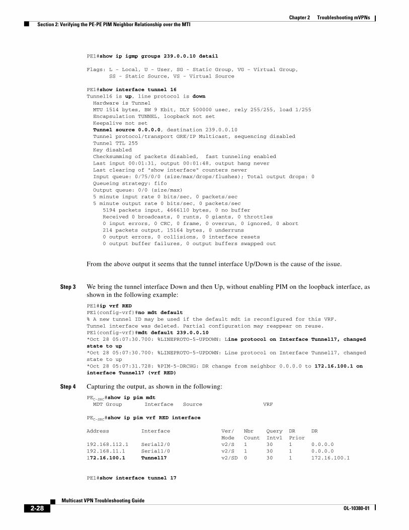
Chapter 2 Troubleshooting mVPNs Section 2: Verifying the PE-PE PIM Neighbor Relationship over the MTI
PE1#show ip igmp groups 239.0.0.10 detail
Flags: L - Local, U - User, SG - Static Group, VG - Virtual Group, SS - Static Source, VS - Virtual Source
PE1#show interface tunnel 16Tunnel16 is up, line protocol is down Hardware is Tunnel MTU 1514 bytes, BW 9 Kbit, DLY 500000 usec, rely 255/255, load 1/255 Encapsulation TUNNEL, loopback not set Keepalive not set Tunnel source 0.0.0.0, destination 239.0.0.10 Tunnel protocol/transport GRE/IP Multicast, sequencing disabled Tunnel TTL 255 Key disabled Checksumming of packets disabled, fast tunneling enabled Last input 00:01:31, output 00:01:48, output hang never Last clearing of "show interface" counters never Input queue: 0/75/0/0 (size/max/drops/flushes); Total output drops: 0 Queueing strategy: fifo Output queue: 0/0 (size/max) 5 minute input rate 0 bits/sec, 0 packets/sec 5 minute output rate 0 bits/sec, 0 packets/sec 5194 packets input, 4666110 bytes, 0 no buffer Received 0 broadcasts, 0 runts, 0 giants, 0 throttles 0 input errors, 0 CRC, 0 frame, 0 overrun, 0 ignored, 0 abort 214 packets output, 15164 bytes, 0 underruns 0 output errors, 0 collisions, 0 interface resets 0 output buffer failures, 0 output buffers swapped out
From the above output it seems that the tunnel interface Up/Down is the cause of the issue.
Step 3 We bring the tunnel interface Down and then Up, without enabling PIM on the loopback interface, as shown in the following example:
PE1#ip vrf RED PE1(config-vrf)#no mdt default % A new tunnel ID may be used if the default mdt is reconfigured for this VRF.Tunnel interface was deleted. Partial configuration may reappear on reuse.PE1(config-vrf)#mdt default 239.0.0.10*Oct 28 05:07:30.700: %LINEPROTO-5-UPDOWN: Line protocol on Interface Tunnel17, changed state to up*Oct 28 05:07:30.700: %LINEPROTO-5-UPDOWN: Line protocol on Interface Tunnel17, changed state to up*Oct 28 05:07:31.728: %PIM-5-DRCHG: DR change from neighbor 0.0.0.0 to 172.16.100.1 on interface Tunnel17 (vrf RED)
Step 4 Capturing the output, as shown in the following:
PEC-SRC#show ip pim mdt MDT Group Interface Source VRF
PEC-SRC#show ip pim vrf RED interface
Address Interface Ver/ Nbr Query DR DR Mode Count Intvl Prior192.168.112.1 Serial2/0 v2/S 1 30 1 0.0.0.0192.168.11.1 Serial1/0 v2/S 1 30 1 0.0.0.0172.16.100.1 Tunnel17 v2/SD 0 30 1 172.16.100.1
PE1#show interface tunnel 17
2-28Multicast VPN Troubleshooting Guide
OL-10380-01
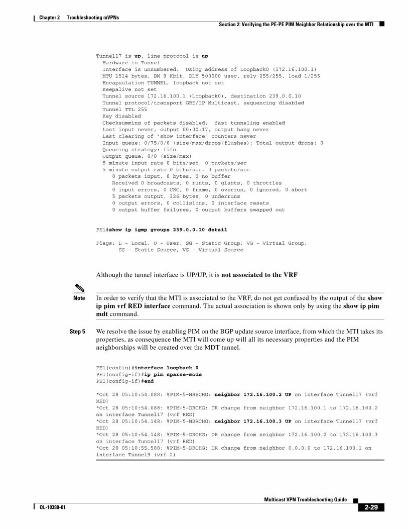
Chapter 2 Troubleshooting mVPNs Section 2: Verifying the PE-PE PIM Neighbor Relationship over the MTI
Tunnel17 is up, line protocol is up Hardware is Tunnel Interface is unnumbered. Using address of Loopback0 (172.16.100.1) MTU 1514 bytes, BW 9 Kbit, DLY 500000 usec, rely 255/255, load 1/255 Encapsulation TUNNEL, loopback not set Keepalive not set Tunnel source 172.16.100.1 (Loopback0), destination 239.0.0.10 Tunnel protocol/transport GRE/IP Multicast, sequencing disabled Tunnel TTL 255 Key disabled Checksumming of packets disabled, fast tunneling enabled Last input never, output 00:00:17, output hang never Last clearing of "show interface" counters never Input queue: 0/75/0/0 (size/max/drops/flushes); Total output drops: 0 Queueing strategy: fifo Output queue: 0/0 (size/max) 5 minute input rate 0 bits/sec, 0 packets/sec 5 minute output rate 0 bits/sec, 0 packets/sec 0 packets input, 0 bytes, 0 no buffer Received 0 broadcasts, 0 runts, 0 giants, 0 throttles 0 input errors, 0 CRC, 0 frame, 0 overrun, 0 ignored, 0 abort 5 packets output, 326 bytes, 0 underruns 0 output errors, 0 collisions, 0 interface resets 0 output buffer failures, 0 output buffers swapped out
PE1#show ip igmp groups 239.0.0.10 detail
Flags: L - Local, U - User, SG - Static Group, VG - Virtual Group, SS - Static Source, VS - Virtual Source
Although the tunnel interface is UP/UP, it is not associated to the VRF
Note In order to verify that the MTI is associated to the VRF, do not get confused by the output of the show ip pim vrf RED interface command. The actual association is shown only by using the show ip pim mdt command.
Step 5 We resolve the issue by enabling PIM on the BGP update source interface, from which the MTI takes its properties, as consequence the MTI will come up will all its necessary properties and the PIM neighborships will be created over the MDT tunnel.
PE1(config)#interface loopback 0PE1(config-if)#ip pim sparse-mode PE1(config-if)#end
*Oct 28 05:10:54.088: %PIM-5-NBRCHG: neighbor 172.16.100.2 UP on interface Tunnel17 (vrf RED) *Oct 28 05:10:54.088: %PIM-5-DRCHG: DR change from neighbor 172.16.100.1 to 172.16.100.2 on interface Tunnel17 (vrf RED)*Oct 28 05:10:54.148: %PIM-5-NBRCHG: neighbor 172.16.100.3 UP on interface Tunnel17 (vrf RED) *Oct 28 05:10:54.148: %PIM-5-DRCHG: DR change from neighbor 172.16.100.2 to 172.16.100.3 on interface Tunnel17 (vrf RED)*Oct 28 05:10:55.588: %PIM-5-DRCHG: DR change from neighbor 0.0.0.0 to 172.16.100.1 on interface Tunnel9 (vrf 2)
2-29Multicast VPN Troubleshooting Guide
OL-10380-01

Chapter 2 Troubleshooting mVPNs Section 2: Verifying the PE-PE PIM Neighbor Relationship over the MTI
Failure Scenario 2: BGP Update Source Interface Shutdown
In this scenario, the tunnel source (loopback 0) interface is shut down:
Step 1 Disable the PIM on the tunnel source interface (loopback 0) in the following example:
PE1(config)#interface loopback 0PE1(config-if)#no ip pimPE1(config-if)#endPE1#*Oct 28 05:01:22.028: %SYS-5-CONFIG_I: Configured from console by console*Oct 28 05:01:25.836: %LINEPROTO-5-UPDOWN: Line protocol on Interface Tunnel16, changed state to down*Oct 28 05:01:25.836: %PIM-5-NBRCHG: neighbor 172.16.100.3 DOWN on interface Tunnel16 (vrf RED) non DR*Oct 28 05:01:25.836: %PIM-5-NBRCHG: neighbor 172.16.100.2 DOWN on interface Tunnel16 (vrf RED) non DR
PE1(config)#int loopback 0PE1(config-if)#shut*Oct 28 05:13:08.788: %LINK-5-CHANGED: Interface Loopback0, changed state to administratively down*Oct 28 05:13:09.808: %LINEPROTO-5-UPDOWN: Line protocol on Interface Loopback0, changed state to down*Oct 28 05:13:12.828: %LINEPROTO-5-UPDOWN: Line protocol on Interface Tunnel17, changed state to down*Oct 28 05:13:12.828: %PIM-5-NBRCHG: neighbor 172.16.100.3 DOWN on interface Tunnel17 (vrf RED) DR*Oct 28 05:13:12.828: %PIM-5-NBRCHG: neighbor 172.16.100.2 DOWN on interface Tunnel17 (vrf RED) non DR
Step 2 Capture output, as shown in the following example:
PE1#show ip pim mdt MDT Group Interface Source VRF#
PE1#show ip pim vrf RED interface
Address Interface Ver/ Nbr Query DR DR Mode Count Intvl Prior192.168.112.1 Serial2/0 v2/S 1 30 1 0.0.0.0192.168.11.1 Serial1/0 v2/S 1 30 1 0.0.0.0172.16.100.1 Tunnel17 v2/SD 0 30 1 0.0.0.0
PE1#show interface tunnel 17Tunnel17 is up, line protocol is down Hardware is Tunnel Interface is unnumbered. Using address of Loopback0 (172.16.100.1) MTU 1514 bytes, BW 9 Kbit, DLY 500000 usec, rely 255/255, load 1/255 Encapsulation TUNNEL, loopback not set Keepalive not set Tunnel source 172.16.100.1 (Loopback0), destination 239.0.0.10 Tunnel protocol/transport GRE/IP Multicast, sequencing disabled Tunnel TTL 255 Key disabled Checksumming of packets disabled, fast tunneling enabled Last input 00:01:36, output 00:01:49, output hang never Last clearing of "show interface" counters never Input queue: 0/75/0/0 (size/max/drops/flushes); Total output drops: 0 Queueing strategy: fifo Output queue: 0/0 (size/max)
2-30Multicast VPN Troubleshooting Guide
OL-10380-01

Chapter 2 Troubleshooting mVPNs Section 2: Verifying the PE-PE PIM Neighbor Relationship over the MTI
5 minute input rate 0 bits/sec, 0 packets/sec 5 minute output rate 0 bits/sec, 0 packets/sec 161 packets input, 143012 bytes, 0 no buffer Received 0 broadcasts, 0 runts, 0 giants, 0 throttles 0 input errors, 0 CRC, 0 frame, 0 overrun, 0 ignored, 0 abort 20 packets output, 1360 bytes, 0 underruns 0 output errors, 0 collisions, 0 interface resets 0 output buffer failures, 0 output buffers swapped out
PE1#show ip igmp groups 239.0.0.10 detail
Flags: L - Local, U - User, SG - Static Group, VG - Virtual Group, SS - Static Source, VS - Virtual Source
Step 3 Bring the tunnel interface form UP/DOWN to UP/UP by issuing removing and re-adding mdt-default:
PE1(config)#ip vrf REDPE1(config-vrf)#no mdt default % A new tunnel ID may be used if the default mdt is reconfigured for this VRF.Tunnel interface was deleted. Partial configuration may reappear on reuse.PE1(config-vrf)#mdt default 239.0.0.10*Oct 28 05:16:16.748: %LINEPROTO-5-UPDOWN: Line protocol on Interface Tunnel18, changed state to up*Oct 28 05:16:16.748: %LINEPROTO-5-UPDOWN: Line protocol on Interface Tunnel18, changed state to down
PE1#show ip pim mdt MDT Group Interface Source VRF* 239.0.0.10 Tunnel18 Loopback0 RED
PE1#show running-config interface loopback 0 Building configuration...
Current configuration : 174 bytes!interface Loopback0 ip address 172.16.100.1 255.255.255.255 no ip directed-broadcast ip pim sparse-mode ip igmp join-group 239.0.0.100 load-interval 30 shutdownend
PE1#show ip igmp groups 239.0.0.10 detail
Flags: L - Local, U - User, SG - Static Group, VG - Virtual Group, SS - Static Source, VS - Virtual Source
PE1#show ip pim vrf RED interface
Address Interface Ver/ Nbr Query DR DR Mode Count Intvl Prior192.168.112.1 Serial2/0 v2/S 1 30 1 0.0.0.0192.168.11.1 Serial1/0 v2/S 1 30 1 0.0.0.0172.16.100.1 Tunnel18 v2/SD 0 30 1 0.0.0.0#
Step 4 Resolving the issue by bring up the loopback interface
PEC-SRC#conf tEnter configuration commands, one per line. End with CNTL/Z.PEC-SRC(config)#int loopback 0
2-31Multicast VPN Troubleshooting Guide
OL-10380-01

Chapter 2 Troubleshooting mVPNs Section 2: Verifying the PE-PE PIM Neighbor Relationship over the MTI
PEC-SRC(config-if)#no shutPEC-SRC(config-if)#end
*Oct 28 05:18:26.420: %SYS-5-CONFIG_I: Configured from console by console*Oct 28 05:18:26.660: %PIM-5-DRCHG: DR change from neighbor 0.0.0.0 to 172.16.100.1 on interface Tunnel18 (vrf RED)*Oct 28 05:18:27.680: %PIM-5-DRCHG: DR change from neighbor 0.0.0.0 to 172.16.100.1 on interface Loopback0 (vrf default)*Oct 28 05:18:27.832: %LINK-3-UPDOWN: Interface Loopback0, changed state to up*Oct 28 05:18:28.072: %LINEPROTO-5-UPDOWN: Line protocol on Interface Tunnel18, changed state to up*Oct 28 05:18:28.852: %LINEPROTO-5-UPDOWN: Line protocol on Interface Loopback0, changed state to up
*Oct 28 05:18:47.480: %PIM-5-NBRCHG: neighbor 172.16.100.2 UP on interface Tunnel18 (vrf RED) *Oct 28 05:18:47.480: %PIM-5-DRCHG: DR change from neighbor 172.16.100.1 to 172.16.100.2 on interface Tunnel18 (vrf RED)*Oct 28 05:18:49.272: %PIM-5-NBRCHG: neighbor 172.16.100.3 UP on interface Tunnel18 (vrf RED) *Oct 28 05:18:49.272: %PIM-5-DRCHG: DR change from neighbor 172.16.100.2 to 172.16.100.3 on interface Tunnel18 (vrf RED)
PE1#show ip pim mdt MDT Group Interface Source VRF* 239.0.0.10 Tunnel18 Loopback0 RED
PE1#show ip pim vrf RED interface
Address Interface Ver/ Nbr Query DR DR Mode Count Intvl Prior192.168.112.1 Serial2/0 v2/S 1 30 1 0.0.0.0192.168.11.1 Serial1/0 v2/S 1 30 1 0.0.0.0172.16.100.1 Tunnel18 v2/SD 2 30 1 172.16.100.3
PE1#show ip igmp groups 239.0.0.10 detail
Flags: L - Local, U - User, SG - Static Group, VG - Virtual Group, SS - Static Source, VS - Virtual Source
Interface: Loopback0Group: 239.0.0.10Flags: VG Uptime: 00:03:29Group mode: INCLUDELast reporter: 0.0.0.0Source list is empty
PE1#show int tunnel 18Tunnel18 is up, line protocol is up Hardware is Tunnel Interface is unnumbered. Using address of Loopback0 (172.16.100.1) MTU 1514 bytes, BW 9 Kbit, DLY 500000 usec, rely 255/255, load 1/255 Encapsulation TUNNEL, loopback not set Keepalive not set Tunnel source 172.16.100.1 (Loopback0), destination 239.0.0.10 Tunnel protocol/transport GRE/IP Multicast, sequencing disabled Tunnel TTL 255 Key disabled Checksumming of packets disabled, fast tunneling enabled Last input 00:00:09, output 00:00:03, output hang never Last clearing of "show interface" counters never Input queue: 0/75/0/0 (size/max/drops/flushes); Total output drops: 0
2-32Multicast VPN Troubleshooting Guide
OL-10380-01

Chapter 2 Troubleshooting mVPNs Section 2: Verifying the PE-PE PIM Neighbor Relationship over the MTI
Queueing strategy: fifo Output queue: 0/0 (size/max) 5 minute input rate 8000 bits/sec, 0 packets/sec 5 minute output rate 0 bits/sec, 0 packets/sec 230 packets input, 207952 bytes, 0 no buffer Received 0 broadcasts, 0 runts, 0 giants, 0 throttles 0 input errors, 0 CRC, 0 frame, 0 overrun, 0 ignored, 0 abort 23 packets output, 1842 bytes, 0 underruns 0 output errors, 0 collisions, 0 interface resets 0 output buffer failures, 0 output buffers swapped out
Checking the Mroute State Information pertaining to the Default MDTGPA on a Specific PE
This section focuses on a specific PE, as defined by the high level diagram in Figure 2-3. Using the state diagram in Figure 2-7, you can check the health of the default MDT in the multicast core network. This diagram helps to check the mroutes (also known as multicast states) in the global table for the mVPN GPA address, defined by the vrf mdt default GPA command.
Specifically, this section guides you through checks on the (*, GPA): existence, Z flag, OIL, IIL, and so forth. Depending on the PIM mode for the default mdt, (S,GPA) states is also checked in Figure 2-8.
The following assumptions are made:
• Default MDT mode is PIM SM with SPT equals to 0 or Bidir.
• PIM neighbors have been checked on all PEs for this mVPN.
• Focus is on the mVPN of a specific enterprise customer, and thus on a specific default MDT.
2-33Multicast VPN Troubleshooting Guide
OL-10380-01

Chapter 2 Troubleshooting mVPNs Section 2: Verifying the PE-PE PIM Neighbor Relationship over the MTI
Figure 2-7 Checking the MROUTE Table for the Default mdt Address Part I
Y e s t o b o t h
Y e s
N o
N o ( P I M - S M i s u s e d )
U s e s h i p m r o u t e < G P A > :- - D o y o u s e e t h e ( S , G P A ) f o r t h e L o c a l P E ?- - S e e N o t e 6
Y e s
A p p l y F i g u r e 2 - 6 t o c h e c k M T I /B G P s e t t i n g s o n t h i s P E o n l y .G o b a c k t o A . 1
N o t e 1
C h e c k t h a t t h e ( * , G P A ) e n t r y h a sa Z f l a g a n d a C F l a g
U s e s h o w i p i g m p g r o u p < G P A > d e t a i l : - - C h e c k t h e M D T c o r e p a r a m e t e r s - - S e e N o t e 3
I f i s s u e r e m a i n s , a p p l y F i g u r e 2 - 6 t o t h i s P Eo n l y ( i f n o t d o n e y e t ) .G o b a c k t o A . 1O p e n a T A C c a s e i f t h e i s s u e i s s t i l l p r e s e n t .
N o
N o
C o r r e c t t h e s e t u p .
I f n e e d e d , c h e c k c o r e - r e l a t e d c o n f i g u r a t i o no n t h i s P E f o r t h e M D T ( U s e S e c t i o n 1 )
G o b a c k t o F 1 0 .
Y e s
O K
U s e s h i p m r o u t e< G P A > : t h e ( * , G P A )e n t r y s h o u l d p r e s e n ta B f l a g
N o
Y e s
A p p l y F i g u r e 2 - 6 t o t h i s P E
I f M T I i n t e r f a c e U P / U Pa n d s t i l l M V R F i s n o t i nt h e O I L , o p e n a T A Cc a s e
N oY e s
Y e s
N o : o u t p u t i n c o r r e c t
N o
F 1 0
U s e s h i p m r o u t e < G P A >
1 ) B i d i r i s e n a b l e d = > O I L s h o u l d a l s o s h o w t h ec o r e i n t e r f a c e t o w a r d s t h e R P a n d p o t e n t i a l l yi n t e r f a c e s t o w a r d s o t h e r d i r e c t l y c o n n e c t e d P E s2 ) C h e c k a l s o t h a t t h e B i d i r U p s t r e a m L i n ec o n t a i n s t h e c o r e i n t e r f a c e l e a d i n g t o t h e R P
O p e n a T A C c a s eI s s u e w i t h t h e o u t p u t
G o t o n e x t s e c t i o n a c c o r d i n g t o t h e h i g h - l e v e l d i a g r a m t h a tr e f e r r e d y o u t o t h i s f i g u r e o r r e t u r n t o t h e s e c t i o n t h a t r e f e r r e dy o u t o c h e c k t h i s s e c t i o n .R e a d N o t e 5 .
N o
R e v i e w S e c t i o n 1 f o r t h i s M D T o n t h e P E .I f t h e i s s u e r e m a i n s , c o n t a c t T A C
C h e c k t h e O I L : S e e N o t e 7C h e c k t h e I I L : S e e N o t e 8
O I L , I I L : O K
C h e c k S e c t i o n 1 “ c h e c k t h e c o r e ” f o r t h e M D T o n t h i s P EN o
A . 1
U s e s h i p m r o u t e - - D o e s t h e ( * , G P A ) e n t r y h a v e a v a l i d R P ? - - I s t h e R P F i n f o f o r t h e R P c o r r e c t ? S e e N o t e 2
C h e c kt h e O I L f o r ( * , G P A ) : i t s h o u l d c o n t a i n M V R F< v r f N a m e >
B i d i r u s e d f o r t h eM D T ?
C h e c k I I L f o r t h e ( * , G P A ) : t h e c o r e i n t e r f a c e t o w a r d st h e R P s h o u l d b e i n t h e I I L
R e c h e c k O I L= > s o l v e d i s s u e ?
U s e s h i p p i m m d t : D o e s t h e M T I e x i s t s f o r t h e G P A ? I s t h e M T I a s s o c i a t e d t o t h e p r o p e r m V R F ?
R e v i e w S e c t i o n 1“ c o r e ” f o r t h e M D TG P A a n d B i d i r m o d e .
I f t h i s w a s d o n e o p e n aT A C c a s e . S e e N o t e 4
2-34Multicast VPN Troubleshooting Guide
OL-10380-01

Chapter 2 Troubleshooting mVPNs Section 2: Verifying the PE-PE PIM Neighbor Relationship over the MTI
Notes for Figure 2-7
Note 1
• Assumptions are the same as those given for Figure 2-4, with respect to the previously checked set of PEs.
• N>=3.
Note 2
• The valid RP address is the proper RP IP address for the range of addresses to which the MDT belongs.
• Note that in the case of Bidir the RP might be a dummy RP.
Note 3
This is an appropriate PIM type for the range to which the MDT belongs.
Note 4
Take into account that RP validity was checked earlier in this section.
Note 5
Your next step is most likely to proceed to Figure 2-8.
Note 6
Remember that it should not have a Z flag. Refer to the sample output.
Note 7
Do you see the core RPF interface towards the RP and the interfaces towards any directly connected PEs?
Note 8
Do you see the BGP update source interface (or BGP Next Hop if any is defined in the VRF) (for instance Loop 0 in our setup)?
2-35Multicast VPN Troubleshooting Guide
OL-10380-01

Chapter 2 Troubleshooting mVPNs Section 2: Verifying the PE-PE PIM Neighbor Relationship over the MTI
Figure 2-8 Checking the MROUTE Table for the Default mdt Address Part II
U s e s h i p m r o u t e < G P A > :D o y o u s e e a l l ( S , G P A ) f o r t h e P E s t h a t b e lo n g t o t h ec u s t o m e r m V P N ]
R e a d N o t e 4I f n o t d o n e y e t a p p l y S e c t io n 1f o r t h e M D T G P A f o r t h e( S , G P A ) a n d r e c h e c k C 1 0
I f t h e i s s u e r e m a in s , o p e n aT A C c a s e
C h e c k t h a t a l lc o n s id e r e d
( S , G P A ) e n t r ie sh a v e a Z f l a g
Y e s
N o : s o m e o r n o n e
C h e c k in c o m in g a n d o u t g o in g c o u n t e r s o nin t e r f a c e a n d c h e c k t h e o u t p u t f o r s h i pm r o u t e c o u n t f o r t h e G P A . S e e N o t e 8 .
1 . U s e s h i p m r o u t e < G P A > t oc h e c k O I L a n d I I L f o r ( S , G P A )e n t r i e s , w h e r e S = o n e o f t h e r e m o t eP e s . S e e N o t e 5 .
2 . U s e s h i p r p f < P E - s o u r c ea d d r e s s > t o c h e c k o n t h e I I L e n t r y( c o r e P E - P i n t e r f a c e ) . S e e N o t e 6 .
3 . C h e c k t h a t t h e R P F n e i g h b o r f o rt h e e a c h s o u r c e r e m o t e P E i s p r o p e ra n d v a l i d .
O KC a l l T A C
G o t o t h e n e x t s e c t i o n a c c o r d in g t o F ig u r e 2 - 3
N o t O K
I f # 1 c h e c k i s n o t O K := > O I L i s in a c c u r a t e a n d y o u a r es u r e t h a t M T I o n t h e l o c a l P E i s U P /U P a n d a s s o c ia t e d w i t h t h e m V R F( s h i p p im m d t ) , c h e c k S e c t i o n 1 .
I f # 2 o r # 3 n o t O K := > c h e c k R P F i n f o ( u n i c a s t t a b le ) .M a k e c o r r e c t io n s i f n e e d e d ( s e eN o t e 7 )
I f R P F i n f o i s a c c u r a t e , c h e c kS e c t i o n 1 f o r t h e d e f a u l t M D T
I f i s s u e s r e m a in , o p e n a T A C c a s e
C h e c k t h a t S P T w a sp r o p e r l y s e t t o
d e f a u l t v a l u e o f 0 .
R e f e r t o N o t e 2 .I f n o t d o n e y e t , a p p ly s e c t i o n
1 f o r t h e ( S , G P A ) .
T h e n r e c h e c k C 1 0 .
I f t h e i s s u e r e m a in s c a l l T A Ca b o u t t h e m is s i n g P E s
P la t f o r m s a n d r e f e r t o n o t e 3
E N T R Y P O I N T : c o m in g f r o m F ig u r e 2 - 7A s s u m p t i o n s a n d p r e l im in a r y c o m m e n t s : s e e N o t e 1
C 1 0
N o n eo f t h e ( S , G P A ) e n t r i e sf o r t h e r e m o t e P E s iss h o w in g i nt h e o u t p u t
S o m eo f t h e ( S , G P A )e n t r i e s f o r t h e r e m o t eP E s a r e i nt h e o u t p u t
A l l r e l e v a n t P E sh a v e ac o r r e s p o n d in g( S , G P A ) e n t r y
2-36Multicast VPN Troubleshooting Guide
OL-10380-01
Chapter 2 Troubleshooting mVPNs Section 2: Verifying the PE-PE PIM Neighbor Relationship over the MTI
Notes for Figure 2-8
Note 1
• This section applies only if Bidir is not the PIM mode for the MDT default. Its goal is to check the (S,GPA) mstates for the remote PEs.
• Remember that the (S,GPA) for the local PE was checked in Figure 2-7.
Note 2
Remember that we are assuming that all remote PEs in the subset have already been checked and are healthy.
Note 3
If you need to call TAC about some PEs for which you see issues, you might want to keep checking the rest of the section and consider only the subset of PEs for which you see an entry (the PEs that are OK).
Note 4
Remember that we are assuming that all PEs in the subset have already been checked and are healthy.
Note 5
• The MVRF should be in the OIL. There might also be some other interface entries.
• In the OIL in case the PE has some leaves on the (S,G) tree besides the MTI.
Note 6
The core RPF interface towards the Source PE (S) should be in the IIL.
Note 7
Corrections for RPF: Ensure that unicast and multicast paths are congruent.
Note 8
• Verify that both incoming and outgoing counters are increasing (there should be at least the PIM control traffic flowing between PEs over the MDT, for example, PE to PE PIM hellos for the (*,GPA)).
• Use the following command:
– Look at interface counters for the Tunnel interface and use the show ip mroute count command for the GPA.
– Verify that the FWDING counter is increasing when repeating this command.
Sample Output and Show Commands to use for Checking the Mroutes for the MDT Tree
The show ip pim rp mapping command allows you to check that the RP has been defined for the MDT default group address; it also ensures that the PIM mode defined for this RP is the one to be used for the default MDT. The following output is for Bidir and PIM SM SPT 0 modes, respectively.
Note you can also use the show ip pim rp-hash group command to check which RP is associated to a specific multicast group on a router, when the RP election mode is BSR or auto-rp.
PE1#show ip pim rp mapping PIM Group-to-RP Mappings
2-37Multicast VPN Troubleshooting Guide
OL-10380-01
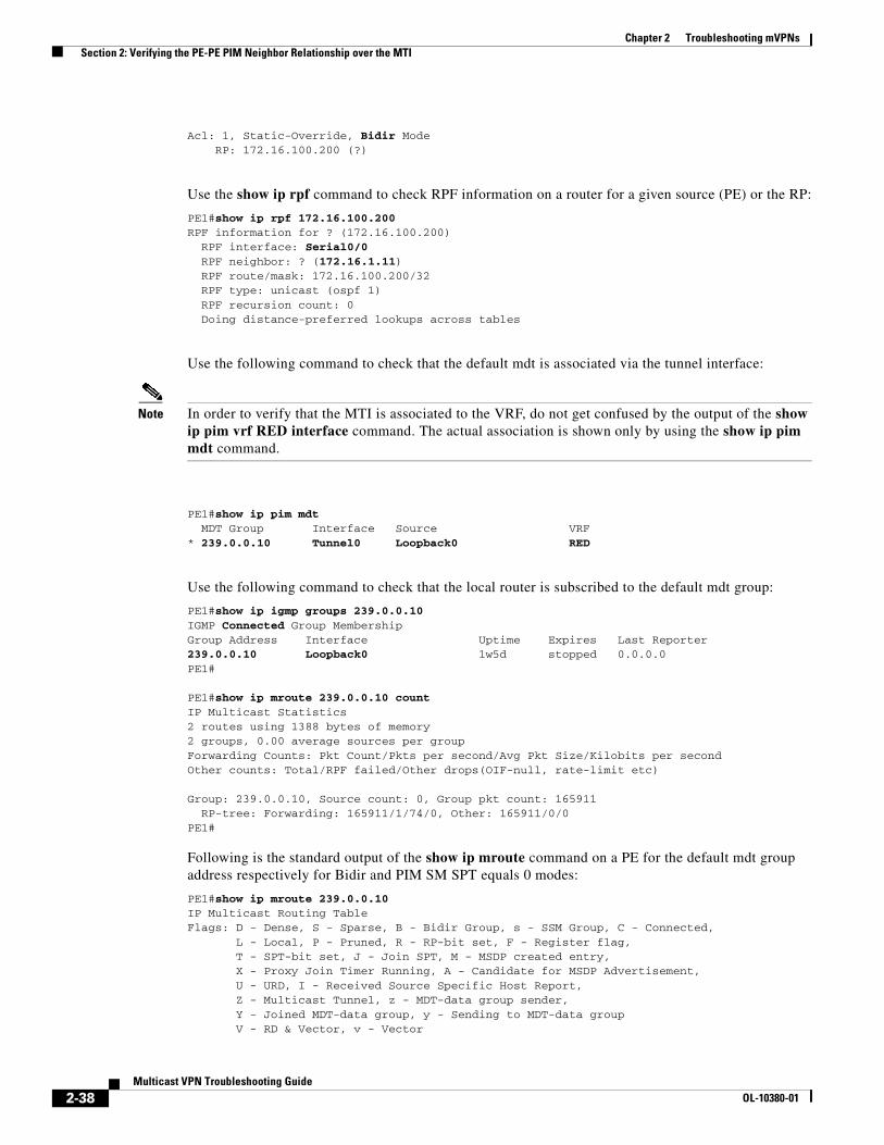
Chapter 2 Troubleshooting mVPNs Section 2: Verifying the PE-PE PIM Neighbor Relationship over the MTI
Acl: 1, Static-Override, Bidir Mode RP: 172.16.100.200 (?)
Use the show ip rpf command to check RPF information on a router for a given source (PE) or the RP:
PE1#show ip rpf 172.16.100.200 RPF information for ? (172.16.100.200) RPF interface: Serial0/0 RPF neighbor: ? (172.16.1.11) RPF route/mask: 172.16.100.200/32 RPF type: unicast (ospf 1) RPF recursion count: 0 Doing distance-preferred lookups across tables
Use the following command to check that the default mdt is associated via the tunnel interface:
Note In order to verify that the MTI is associated to the VRF, do not get confused by the output of the show ip pim vrf RED interface command. The actual association is shown only by using the show ip pim mdt command.
PE1#show ip pim mdt MDT Group Interface Source VRF* 239.0.0.10 Tunnel0 Loopback0 RED
Use the following command to check that the local router is subscribed to the default mdt group:
PE1#show ip igmp groups 239.0.0.10IGMP Connected Group MembershipGroup Address Interface Uptime Expires Last Reporter239.0.0.10 Loopback0 1w5d stopped 0.0.0.0PE1#
PE1#show ip mroute 239.0.0.10 countIP Multicast Statistics2 routes using 1388 bytes of memory2 groups, 0.00 average sources per groupForwarding Counts: Pkt Count/Pkts per second/Avg Pkt Size/Kilobits per secondOther counts: Total/RPF failed/Other drops(OIF-null, rate-limit etc)
Group: 239.0.0.10, Source count: 0, Group pkt count: 165911 RP-tree: Forwarding: 165911/1/74/0, Other: 165911/0/0PE1#
Following is the standard output of the show ip mroute command on a PE for the default mdt group address respectively for Bidir and PIM SM SPT equals 0 modes:
PE1#show ip mroute 239.0.0.10IP Multicast Routing TableFlags: D - Dense, S - Sparse, B - Bidir Group, s - SSM Group, C - Connected, L - Local, P - Pruned, R - RP-bit set, F - Register flag, T - SPT-bit set, J - Join SPT, M - MSDP created entry, X - Proxy Join Timer Running, A - Candidate for MSDP Advertisement, U - URD, I - Received Source Specific Host Report, Z - Multicast Tunnel, z - MDT-data group sender, Y - Joined MDT-data group, y - Sending to MDT-data group V - RD & Vector, v - Vector
2-38Multicast VPN Troubleshooting Guide
OL-10380-01
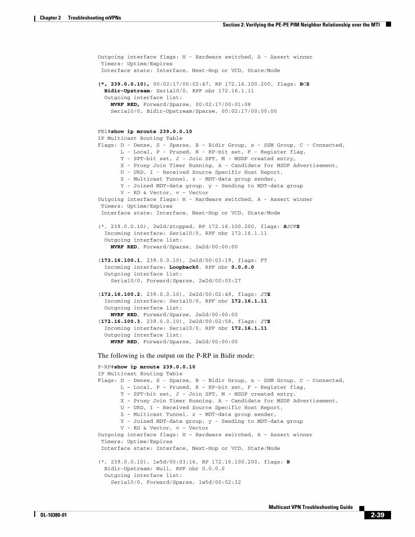
Chapter 2 Troubleshooting mVPNs Section 2: Verifying the PE-PE PIM Neighbor Relationship over the MTI
Outgoing interface flags: H - Hardware switched, A - Assert winner Timers: Uptime/Expires Interface state: Interface, Next-Hop or VCD, State/Mode
(*, 239.0.0.10), 00:02:17/00:02:47, RP 172.16.100.200, flags: BCZ Bidir-Upstream: Serial0/0, RPF nbr 172.16.1.11 Outgoing interface list: MVRF RED, Forward/Sparse, 00:02:17/00:01:08 Serial0/0, Bidir-Upstream/Sparse, 00:02:17/00:00:00
PE1#show ip mroute 239.0.0.10IP Multicast Routing TableFlags: D - Dense, S - Sparse, B - Bidir Group, s - SSM Group, C - Connected, L - Local, P - Pruned, R - RP-bit set, F - Register flag, T - SPT-bit set, J - Join SPT, M - MSDP created entry, X - Proxy Join Timer Running, A - Candidate for MSDP Advertisement, U - URD, I - Received Source Specific Host Report, Z - Multicast Tunnel, z - MDT-data group sender, Y - Joined MDT-data group, y - Sending to MDT-data group V - RD & Vector, v - VectorOutgoing interface flags: H - Hardware switched, A - Assert winner Timers: Uptime/Expires Interface state: Interface, Next-Hop or VCD, State/Mode
(*, 239.0.0.10), 2w2d/stopped, RP 172.16.100.200, flags: SJCFZ Incoming interface: Serial0/0, RPF nbr 172.16.1.11 Outgoing interface list: MVRF RED, Forward/Sparse, 2w2d/00:00:00
(172.16.100.1, 239.0.0.10), 2w2d/00:03:19, flags: FT Incoming interface: Loopback0, RPF nbr 0.0.0.0 Outgoing interface list: Serial0/0, Forward/Sparse, 2w2d/00:03:27
(172.16.100.2, 239.0.0.10), 2w2d/00:02:49, flags: JTZ Incoming interface: Serial0/0, RPF nbr 172.16.1.11 Outgoing interface list: MVRF RED, Forward/Sparse, 2w2d/00:00:00(172.16.100.3, 239.0.0.10), 2w2d/00:02:58, flags: JTZ Incoming interface: Serial0/0, RPF nbr 172.16.1.11 Outgoing interface list: MVRF RED, Forward/Sparse, 2w2d/00:00:00
The following is the output on the P-RP in Bidir mode:
P-RP#show ip mroute 239.0.0.10IP Multicast Routing TableFlags: D - Dense, S - Sparse, B - Bidir Group, s - SSM Group, C - Connected, L - Local, P - Pruned, R - RP-bit set, F - Register flag, T - SPT-bit set, J - Join SPT, M - MSDP created entry, X - Proxy Join Timer Running, A - Candidate for MSDP Advertisement, U - URD, I - Received Source Specific Host Report, Z - Multicast Tunnel, z - MDT-data group sender, Y - Joined MDT-data group, y - Sending to MDT-data group V - RD & Vector, v - VectorOutgoing interface flags: H - Hardware switched, A - Assert winner Timers: Uptime/Expires Interface state: Interface, Next-Hop or VCD, State/Mode
(*, 239.0.0.10), 1w5d/00:03:16, RP 172.16.100.200, flags: B Bidir-Upstream: Null, RPF nbr 0.0.0.0 Outgoing interface list: Serial0/0, Forward/Sparse, 1w5d/00:02:32
2-39Multicast VPN Troubleshooting Guide
OL-10380-01
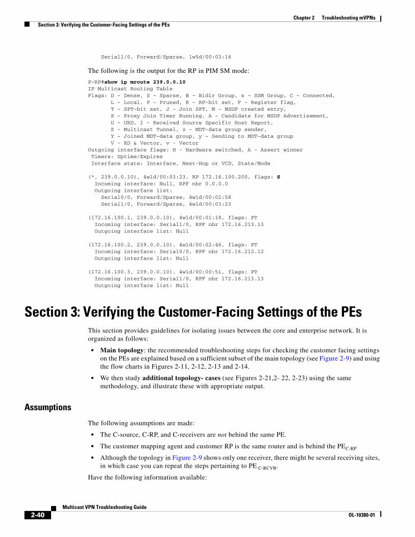
Chapter 2 Troubleshooting mVPNs Section 3: Verifying the Customer-Facing Settings of the PEs
Serial1/0, Forward/Sparse, 1w5d/00:03:16
The following is the output for the RP in PIM SM mode:
P-RP#show ip mroute 239.0.0.10IP Multicast Routing TableFlags: D - Dense, S - Sparse, B - Bidir Group, s - SSM Group, C - Connected, L - Local, P - Pruned, R - RP-bit set, F - Register flag, T - SPT-bit set, J - Join SPT, M - MSDP created entry, X - Proxy Join Timer Running, A - Candidate for MSDP Advertisement, U - URD, I - Received Source Specific Host Report, Z - Multicast Tunnel, z - MDT-data group sender, Y - Joined MDT-data group, y - Sending to MDT-data group V - RD & Vector, v - VectorOutgoing interface flags: H - Hardware switched, A - Assert winner Timers: Uptime/Expires Interface state: Interface, Next-Hop or VCD, State/Mode
(*, 239.0.0.10), 4w1d/00:03:23, RP 172.16.100.200, flags: S Incoming interface: Null, RPF nbr 0.0.0.0 Outgoing interface list: Serial0/0, Forward/Sparse, 4w1d/00:02:58 Serial1/0, Forward/Sparse, 4w1d/00:03:23
(172.16.100.1, 239.0.0.10), 4w1d/00:01:18, flags: PT Incoming interface: Serial1/0, RPF nbr 172.16.213.13 Outgoing interface list: Null
(172.16.100.2, 239.0.0.10), 4w1d/00:02:46, flags: PT Incoming interface: Serial0/0, RPF nbr 172.16.212.12 Outgoing interface list: Null
(172.16.100.3, 239.0.0.10), 4w1d/00:00:51, flags: PT Incoming interface: Serial1/0, RPF nbr 172.16.213.13 Outgoing interface list: Null
Section 3: Verifying the Customer-Facing Settings of the PEs This section provides guidelines for isolating issues between the core and enterprise network. It is organized as follows:
• Main topology: the recommended troubleshooting steps for checking the customer facing settings on the PEs are explained based on a sufficient subset of the main topology (see Figure 2-9) and using the flow charts in Figures 2-11, 2-12, 2-13 and 2-14.
• We then study additional topology- cases (see Figures 2-21,2- 22, 2-23) using the same methodology, and illustrate these with appropriate output.
Assumptions
The following assumptions are made:
• The C-source, C-RP, and C-receivers are not behind the same PE.
• The customer mapping agent and customer RP is the same router and is behind the PEC-RP
• Although the topology in Figure 2-9 shows only one receiver, there might be several receiving sites, in which case you can repeat the steps pertaining to PE C-RCVR.
Have the following information available:
2-40Multicast VPN Troubleshooting Guide
OL-10380-01

Chapter 2 Troubleshooting mVPNs Section 3: Verifying the Customer-Facing Settings of the PEs
• Customer VRF name.
• Customer source IP address(es) and C-SRC.
• Group address(es) and C-GPA.
• Sites (PE and circuit) that connect to the receiver or receivers’ IP addresses.
• Customer RP mode (AutoRP, static RP, bidir) and RP address.
• Customer PIM mode, and if running PIM SM, the threshold configuration specified for switching from shared tree to source tree.
Note This section covers only PIM SM (with static RP or AutoRP).
Main Topology for troubleshooting Customer-Facing Settings on the PEsNormally, mVPN customers open a trouble ticket with the following problem definition:
• No multicast traffic is received at one or all sites.
• Intermittent traffic issues are occurring, which can include slowness and less throughput for the receiving applications.
For these scenarios, the troubleshooting steps take into account the control and the customer data plane. First, verify the control plane, which includes checking the performance of the multicast route states on the PEC-SRC, PEC-RCVR, and PEC-RP . When the Mroute states are verified, check the data flow traffic rates and identify traffic drops.
Figure 2-9 shows the topology used for troubleshooting the issues described in this section.
Note that this figure considers a subset of the global topology (Figure 1-1) used throughout this troubleshooting guide. The multicast core network of the service provider is represented virtually by the MTI LAN interface.
2-41Multicast VPN Troubleshooting Guide
OL-10380-01
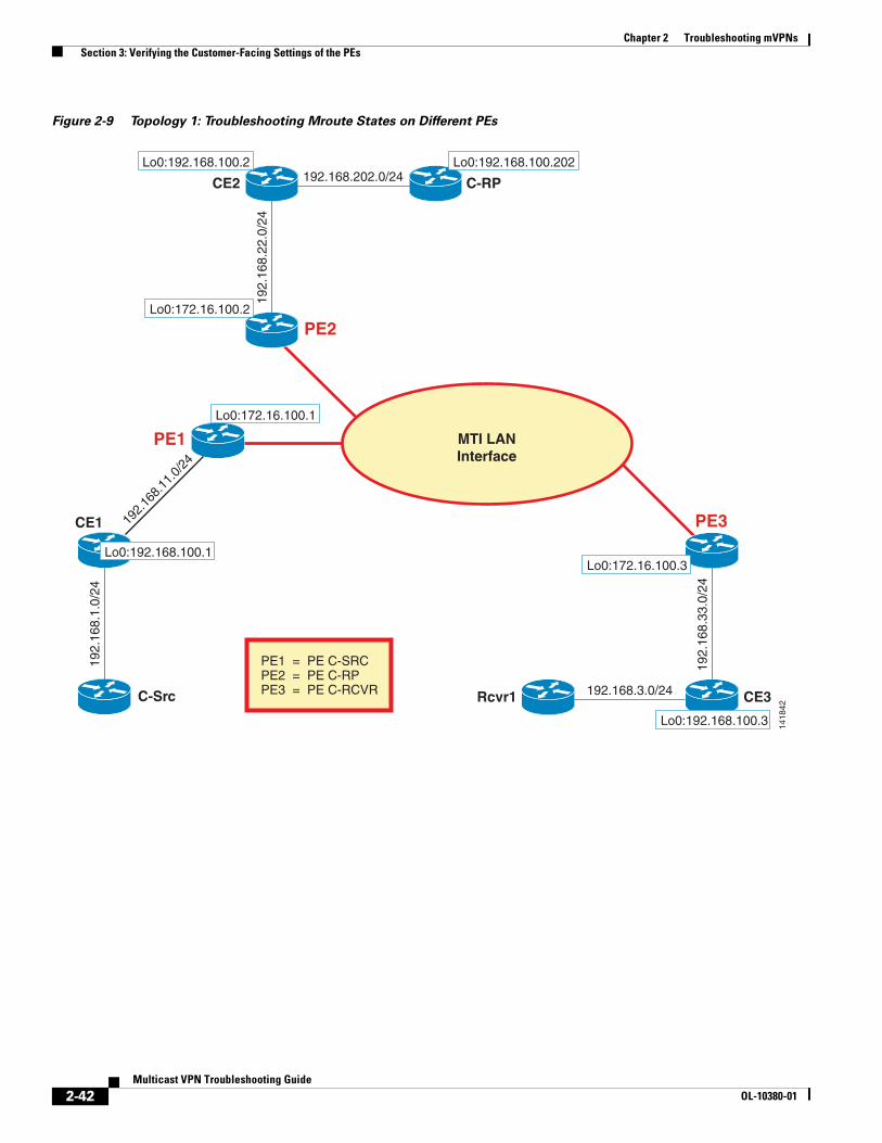
Chapter 2 Troubleshooting mVPNs Section 3: Verifying the Customer-Facing Settings of the PEs
Figure 2-9 Topology 1: Troubleshooting Mroute States on Different PEs
PE1
CE2 C-RP192.168.202.0/24
Rcvr1 192.168.3.0/24
PE2
192.
168.
22.0
/24
CE1
192.
168.
1.0/
24
C-Src
192.
168.
11.0
/24
PE3
CE319
2.16
8.33
.0/2
4
Lo0:192.168.100.2 Lo0:192.168.100.202
Lo0:172.16.100.2
Lo0:172.16.100.1
Lo0:192.168.100.1
Lo0:192.168.100.3
Lo0:172.16.100.3
1418
42
MTI LANInterface
PE1 = PE C-SRCPE2 = PE C-RPPE3 = PE C-RCVR
2-42Multicast VPN Troubleshooting Guide
OL-10380-01

Chapter 2 Troubleshooting mVPNs Section 3: Verifying the Customer-Facing Settings of the PEs
High-Level Diagram for Troubleshooting the Customer-Facing Settings on the PEs
Figure 2-10 provides the high-level diagram for checking the control plane. It is the main figure and should serve as reference point for the other topologies as well.
We start by checking for basic information on the PEC-RP, PEC-SRC, and PEC-RCVR. After verification, we move to check the Mroute states for C-GPA and finally verify the data plane for failures.
Assumptions
• Ensure that you have the VRF name, C-GPA, C-SRC, C-RP & PIM mode information ready.
• We repeat the check for each Source and receiver PE for this C-GPA.
Figure 2-10 High-Level Diagram for Troubleshooting the Control Plane
Verify the following on the PEs:
• Multicast routing is enabled for the mVRF.
• PEs and CEs are PIM neighbors in the VRF context.
• MTI tunnel interface is up and is associated to the mVRF.
• Fast Switching is enabled on the PE-CE interfaces.
• RPF checks towards C-SRC and C-RP are valid.
• Presence of filters (for example, multicast boundary).
• C-RP information is available, and if AutoRP mode is used, verify that AutoRP information is received on PEC-RP.
2-43Multicast VPN Troubleshooting Guide
OL-10380-01

Chapter 2 Troubleshooting mVPNs Section 3: Verifying the Customer-Facing Settings of the PEs
Verifying Customer-Facing Settings on the PEC-RP
The flowchart in Figure 2-11 walks through the basic checks on the PEC-RP .
2-44Multicast VPN Troubleshooting Guide
OL-10380-01

Chapter 2 Troubleshooting mVPNs Section 3: Verifying the Customer-Facing Settings of the PEs
Figure 2-11 Basic Check on PEC-RP
N o t e 1 U s e s h o w i p p i m m d t | i n c < v r f n a m e > o r s h o w i p p i mm d t : I s t h e r e a n M T I f o r t h e c u s t o m e r ’ s V R F ?E n s u r e M D T g r o u p i s c o r r e c t .
N o
U s e s h o w i p p i m v r f < v r f _ n a m e >n e i g h b o r
D o y o u s e e P E C - R C V R a n d P E C - S R C a s P I Mn e i g h b o r s o v e r M T I ?
N o
D o y o u s e e a l l e x p e c t e d P E - C E P I Mn e i g h b o r s ?
N o A p p l y S e c t i o n 3 : “ T r o u b l e s h o o t i n g t h e P I M A d j a c e n c y w i t h t h eC E ( s ) ” ( F i g u r e 2 - 1 9 ) t h e n r e t u r n t o A 1 . 1
A p p l y “ T r o u b l e s h o o t i n g t h e P I M n e i g h b o r s h i p o n a s p e c i f i cP E ” ( F i g u r e 2 - 4 a n d 2 - 5 ) , t h e n r e t u r n t o A 1 . 1
A p p l y “ C h e c k i n g t h e M T I I n t e r f a c e S t a t u s a n d B G P S e t t i n g so n a S p e c i f i c P E ” ( F i g u r e 2 - 6 ) , t h e n r e t u r n t o A 1 . 0
A 1 . 0
A 1 . 1
Y e s
Y e s
Y e s
U s e s h o w i p m u l t i c a s t v r f < v r f _ n a m e >I s M u l t i c a s t R o u t in g e n a b l e d ?
U s e s h o w i p p i m v r f < v r f _ n a m e > i n t e r f a c e c o u n tD o y o u s e e t h e F a s t S w i t c h i n g F l a g u n d e r e a c h i n t e r f a c e ?
C o n f i g u r e i p m u l t i c a s t - r o u t i n g v r f < v r f _ n a m e > , t h e nr e t u r n t o A 1 . 2
A 1 . 2N o
N o C o n f i g u r e i p m r o u t e - c a c h e u n d e r a l l n a t i v e P E - C E i n t e r f a c e s , t h e n r e t u r nt o A 1 . 3
M o v e t o F i g u r e 2 - 1 2
S t a t i c R P
U s e s h o w i p m u l t i c a s t v r f < v r f _ n a m e >I s M u l t i c a s t F a l l b a c k g r o u p m o d e s e t t o S p a r s e ” ?
Y e s
N o
S e e N o t e 2 .
S e r v i c e P r o v i d e r s n o r m a l l y p r e f e r t o h a v e c u s t o m e r ’ s V R F f a l l b a c k g r o u pm o d e s e t t o S p a r s e . E n s u r e t h a t t h i s i s t h e c a s e
R e t u r n t o A 1 . 3
I s t h e r e i p m u l t i c a s t b o u n d a r y c o m m a n d c o n f i g u r e d o n a n yo f t h e n a t i v e P E - C E i n t e r f a c e s ?
N o
I s t h e A C L b l o c k i n g t h e C - G P A r a n g e ?
Y e s
R e c o n f ig u r e t h e A C L t o a l l o w t h e C - G P A r a n g e . R e t u r n t oA 1 . 6
Y e s
U s e s h o w i p r p f v r f < v r f _ n a m e > < C - R P >D o y o u s e e a n e r r o r m e s s a g e s a y i n g ? R P F i n f o r m a t i o n f o r ?( < C - R P > ) f a i l e d , n o r o u t e e x i s t s ?
U s e s h o w i p r o u t e v r f < v r f _ n a m e >< C - R P > . I s t h e d i r e c t l y c o n n e c t e dC E t h e n e x t h o p f o r t h e r o u t e ?
R e a d N o t e 4 :i t i s a u n i c a s t r o u t i n gi s s u e . F i x t h e i s s u e t h e nr e t u r n t o A 1 . 4
N oY e sA 1 . 4
Y e s
F i x t h e I P N H : s e eN o t e 5 . R e t u r n t oA 1 . 4
I s t h e N H t h e s a m e i p a d d r e s s t h a t y o u p e e r w i t h i ns h o w i p p i m v r f < v r f _ n a m e > n e i g h b o r ? N o
C o n t a c t C i s c o T A C
Y e s
N o
V e r i f y t h a t t h e R P F n e i g h b o r i s a d i r e c t l y c o n n e c t e d C E & t h eR P F i n t e r f a c e i s t h e n a t i v e P E - C E I n t e r f a c e
U s e s h o w i p r p f v r f < v r f _ n a m e > < C - S r c >D o y o u s e e a n e r r o r m e s s a g e s a y i n g ” R P F i n f o r m a t i o nf o r < C - S r c > f a i l e d , n o r o u t e e x i s t s ” ?
U s e s h o w i p r o u t e v r f < v r f _ n a m e > < C - S R C > .N o t e t h e N H . I s P E C - S r c t h e N H f o r t h e R o u t e ?Y e s
Y e s
R e a d N o t e 7F i x t h e i s s u e o nP E C - S r cR e t u r n t o A 1 . 5
I s t h e N H t h e s a m e I P a d d r e s s t h a t y o u p e e r w i t hi n s h o w i p p i m v r f < v r f _ n a m e > n e i g h b o r ?
C o n t a c t C i s c o T A C
Y e s
R e a d N o t e 6 .F i x t h e u n i c a s tr o u t i n g i s s u eR e t u r n t o A 1 . 5
N o
N oV e r i f y t h e f o l l o w i n g : - - R P F n e i g h b o r i s P E C - S R C - - R P F i n t e r f a c e i s t h e M T I
N o
A u t o R P
M a k e a p p r o p r i a t e R Pv a l i d i t y v e r i f i c a t i o n ss e e N o t e 3
A 1 . 3
W h a t i s t h e R PE l e c t i o n m e c h a n i s m f o r
t h i s c u s t o m e r ?
A 1 . 5
A 1 . 6
2-45Multicast VPN Troubleshooting Guide
OL-10380-01

Chapter 2 Troubleshooting mVPNs Section 3: Verifying the Customer-Facing Settings of the PEs
Notes for Figure 2-11
Note 1
NH = next hop.
Note 2
For more information, refer to the following URL:
http://www.cisco.com/univercd/cc/td/doc/product/software/ios123/123newft/123t/123t_4/gtautorp.htm.
Note 3
PIM SM with Static RP: verify that ip pim rp-address vrf vrf_name C-RP-address [group-list ACL] [override] exists on the PE and that the ACL reference is correct.
Note 4
If you do not see the prefix, or if the NH is a node other then the directly connected CE, then it is a unicast routing issue.
Note 5
• The IP NH for the prefix to reach the C-RP needs to be a PIM neighbor as well.
• If there are any fancy route maps on the CE or the PE (C-RP), verify that these do not interfere with the control plane and modify accordingly.
Note 6
If you do not see the prefix, or the NH is a node other then the PEC-SRC, then it is a unicast routing issue.
Note 7
• If the NH is one of the IP addresses on PEC-SRC that is not the same ip address as the PIM neighbor over MTI Interface, then mVPN will break.
• All PEs must advertise prefixes with BGP next hop, which is the tunnel source loopback ip address.
Sample Output for Checks of the PE Settings on the Customer RP Site
Step 1 Performing basic checks on PEC-RP on the sanity of the MTI:
PE2#show ip multicast vrf REDMulticast Routing: enabledMulticast Multipath: disabledMulticast Route limit: No limitMulticast Triggered RPF check: enabledMulticast Fallback group mode: Sparse
PE2#show ip pim mdt | include MDT|REDMDT Group Interface Source VRF* 239.0.0.10 Tunnel0 Loopback0 RED
PE2#show ip pim vrf RED neighborPIM Neighbor TableNeighbor Interface Uptime/Expires Ver DRAddress Priority/Mode192.168.22.2 Serial1/0 2d04h/00:01:37 v2 1 / P172.16.100.1 Tunnel0 00:04:46/00:01:24 v2 1 / P172.16.100.3 Tunnel0 2d04h/00:01:25 v2 1 / DR P
2-46Multicast VPN Troubleshooting Guide
OL-10380-01

Chapter 2 Troubleshooting mVPNs Section 3: Verifying the Customer-Facing Settings of the PEs
PE2#show ip pim interface S1/0 detailSerial1/0 is up, line protocol is upInternet address is 192.168.22.1/24Multicast switching: fastMulticast packets in/out: 5614/161535Multicast boundary: not setMulticast TTL threshold: 0PIM: enabledPIM version: 2, mode: sparsePIM DR: 0.0.0.0PIM neighbor count: 1PIM Hello/Query interval: 30 secondsPIM NBMA mode: disabledPIM ATM multipoint signalling: disabledPIM domain border: disabledPIM neighbors rpf proxy capable: TRUEMulticast Tagswitching: disabled
Step 2 Ensure that the RP address is known in the VRF at the PE level:
PE2#show ip rpf vrf RED 192.168.100.202 C-RPRPF information for ? (192.168.100.202)RPF interface: Serial1/0RPF neighbor: ? (192.168.22.2)RPF route/mask: 192.168.100.202/32RPF type: unicast (bgp 1)RPF recursion count: 1Doing distance-preferred lookups across tables
PE2#show ip rpf vrf RED 192.168.11.1 C-SrcRPF information for ? (192.168.11.1)RPF interface: Tunnel0RPF neighbor: ? (172.16.100.1)RPF route/mask: 192.168.11.0/24RPF type: unicast (bgp 1)RPF recursion count: 0Doing distance-preferred lookups across tablesBGP originator: 172.16.100.1
Step 3 After the above is verified, the next step is to check the RP mapping on PEC-RP .
Use the show ip pim rp mapping command for this purpose. Note the following configuration checks:
• Static RP mapping
If the customer is running static RP, verify that all the PEs in the mVRF are configured with the correct static RP:
ip pim rp-address rp-address [group_acl] [override]
It is recommended to use the override keyword to override the dynamically learned RP mappings. Also verify that the value specified by group_acl is correctly configured in the ACL and correctly referenced in the above command.
• AutoRP mapping using Cisco AutoRP
For AutoRP, verify the following:
– PEC-RP learns the RP mapping from the CE side through AutoRP (show ip pim rp-hash in the vrf context)
– AutoRP advertises the RP mapping to the rest of the PEs connected on the MTI
2-47Multicast VPN Troubleshooting Guide
OL-10380-01

Chapter 2 Troubleshooting mVPNs Section 3: Verifying the Customer-Facing Settings of the PEs
The flowchart in Figure 2-12 walks through the essential configuration of AutoRP on PEC-RP.
Figure 2-12 AutoRP Troubleshooting on PEC-RP
Y e s
Y es
Is A u toR P lis te ne r co n figu redfo r th is V R F ?P roced u re : S e e N o te 1
N oC on fig u re ip p im v rf< v rf_ na m e > au to rplis ten e r
E ith e r con fig u re a ll P E -C E in te rfaces in P IMsp a rse -de nse m o de o r e na b le A u toR P lis ten e r
A lso con fig u re an R P o f la s t re so rt. S e e N o te 3
Is th e re an y m u ltica s t b ou nd a ry s ta tem e n tcon fig u re d o n the P E -C E in te rfa ceto w a rd s C -R P ?
Y e s
Is th e A C L b lock ing the A u toR P g rou ps?
N oU se d e b ug ip p im v rf < v rf_n am e> a u to rp a ndw a it fo r 90 se cs .A re the re a ny A u toR P m e ssag e s? (see N o te 6 )
P rob ab ly cu s to m e r s ideissu e .O b ta in ou tpu ts an dco n ta c t T A C p e r N o te 7
Y e s
R e co n fig u re th e A C L to a llow theA u to R P g ro up s . R e tu rn to A 1 .7
U se s ho w ip p im v rf < vrf_ na m e >in te rfac eA re a ll P E -C E in te rfaces en ab le d fo r P IMspa rse m o de o n ly?
N o
N oY es
U se s ho w ip p im v rf < vrf_ na m e> rpm ap p in gD o yo u see a n R P a dd ress cove rin g thecus tom e r G P A ran ge ?
Is th is theco rrec t R P ?
Y es
A 1 .7 V e rify th a t the M D T T un ne l in te rface is in th eO IL o f (S ,G ) en try fo r 2 24 .0 .1 .4 0 an d2 24 .0 .1 .3 9.S e e N o te 4
N o
A re a ll P E -C E in te rfaces co n figu red fo rP IM sp a rse -de nse m o de ?
N o R e tu rn to A 1 .7
Y e s
Y es
N o
N o
C on tac t C isco T A C
Y e s
S tartN o te 2
N o
R e p o rt to the cus tom er a nd a d ju s tse tting s as ne ed ed , see N o te 5R e tu rn to A 1 .7
M ove to the F ig u re 2 -1 3w ith in th e S e ction “B as ic ch eck o n P E C -S rc ”
2-48Multicast VPN Troubleshooting Guide
OL-10380-01
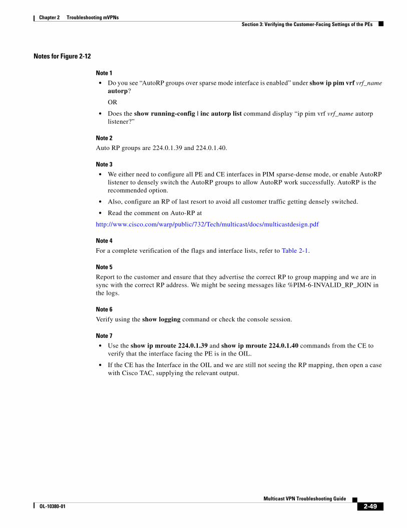
Chapter 2 Troubleshooting mVPNs Section 3: Verifying the Customer-Facing Settings of the PEs
Notes for Figure 2-12
Note 1
• Do you see “AutoRP groups over sparse mode interface is enabled” under show ip pim vrf vrf_name autorp?
OR
• Does the show running-config | inc autorp list command display “ip pim vrf vrf_name autorp listener?”
Note 2
Auto RP groups are 224.0.1.39 and 224.0.1.40.
Note 3
• We either need to configure all PE and CE interfaces in PIM sparse-dense mode, or enable AutoRP listener to densely switch the AutoRP groups to allow AutoRP work successfully. AutoRP is the recommended option.
• Also, configure an RP of last resort to avoid all customer traffic getting densely switched.
• Read the comment on Auto-RP at
http://www.cisco.com/warp/public/732/Tech/multicast/docs/multicastdesign.pdf
Note 4
For a complete verification of the flags and interface lists, refer to Table 2-1.
Note 5
Report to the customer and ensure that they advertise the correct RP to group mapping and we are in sync with the correct RP address. We might be seeing messages like %PIM-6-INVALID_RP_JOIN in the logs.
Note 6
Verify using the show logging command or check the console session.
Note 7
• Use the show ip mroute 224.0.1.39 and show ip mroute 224.0.1.40 commands from the CE to verify that the interface facing the PE is in the OIL.
• If the CE has the Interface in the OIL and we are still not seeing the RP mapping, then open a case with Cisco TAC, supplying the relevant output.
2-49Multicast VPN Troubleshooting Guide
OL-10380-01

Chapter 2 Troubleshooting mVPNs Section 3: Verifying the Customer-Facing Settings of the PEs
Sample Output for Checks on the PE Located Close to the Customer RP, with AutoRP in the Customer Network
The following example shows output from PEC-RP for mroutes of AutoRP groups:
(*, 224.0.1.39), 00:14:20/stopped, RP 0.0.0.0, flags: D Incoming interface: Null, RPF nbr 0.0.0.0 Outgoing interface list: Serial1/0, Forward/Sparse, 00:14:20/00:00:00 Tunnel0, Forward/Sparse-Dense, 00:14:20/00:00:00
(192.168.100.202, 224.0.1.39), 00:02:21/00:01:09, flags: PT Incoming interface: Serial1/0, RPF nbr 192.168.22.2 Outgoing interface list: Tunnel0, Prune/Sparse-Dense, 00:02:15/00:01:08
PE2#show ip mroute vrf RED 224.0.1.40 | begin 224(*, 224.0.1.40), 00:15:59/stopped, RP 0.0.0.0, flags: DCL Incoming interface: Null, RPF nbr 0.0.0.0 Outgoing interface list: Serial1/0, Forward/Sparse, 00:15:59/00:00:00 Tunnel0, Forward/Sparse-Dense, 00:15:59/00:00:00
Table 2-1 VRF Mroute states on PEC-RP for AutoRP Groups
For (*,224.0.1.39)
RP 0.0.0.0, Flags = D
Incoming interface Null, RPF neighbor 0.0.0.0
Outgoing interfaces Default mdt tunnel interface plus all native PE-CE interfaces
For (S,224.0.1.39)
Flags PT (flag P is there because the assumption is that the customer mapping agent /RP candidate is the same router and on the local site)
Incoming interface PE-CE interface closest to the RP and RPF neighbor CE router
Outgoing interfaces Default mdt tunnel interface plus any additional native PE-CE interfaces, excluding the IIL
For (*,224.0.1.40)
RP 0.0.0.0, flags: DCL
Incoming interface Null, RPF neighbor 0.0.0.0
Outgoing interfaces Default mdt tunnel interface plus all native PE-CE interfaces
For (S,224.0.1.40)
Flags: LT
Incoming interface PE-CE interface closest to the RP and RPF neighbor CE router
Outgoing interfaces Default mdt tunnel interface plus any additional native PE-CE interfaces, excluding the IIL
2-50Multicast VPN Troubleshooting Guide
OL-10380-01

Chapter 2 Troubleshooting mVPNs Section 3: Verifying the Customer-Facing Settings of the PEs
(192.168.100.202, 224.0.1.40), 00:15:06/00:02:48, flags: LT Incoming interface: Serial1/0, RPF nbr 192.168.22.2 Outgoing interface list: Tunnel0, Forward/Sparse-Dense, 00:15:06/00:00:00
Verifying Customer-Facing Settings on the PEC-SRC
The flowchart in Figure 2-13 walks through the basic checks on the PEC-SRC.
2-51Multicast VPN Troubleshooting Guide
OL-10380-01
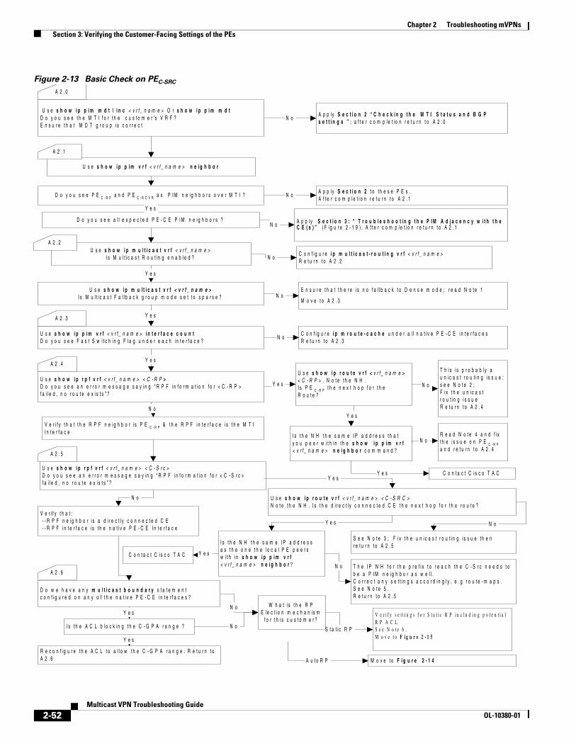
Chapter 2 Troubleshooting mVPNs Section 3: Verifying the Customer-Facing Settings of the PEs
Figure 2-13 Basic Check on PEC-SRC
U s e s h o w i p p i m m d t | i n c < v r f _ n a m e > O r s h o w i p p i m m d tD o y o u s e e t h e M T I f o r t h e c u s t o m e r ’ s V R F ?E n s u r e t h a t M D T g r o u p i s c o r r e c t
N o
U s e s h o w i p p i m v r f < v r f _ n a m e > n e i g h b o r
D o y o u s e e P E C - R P a n d P E C - R C V R a s P I M n e i g h b o r s o v e r M T I ? N o
D o y o u s e e a l l e x p e c t e d P E - C E P I M n e i g h b o r s ?N o A p p l y S e c t i o n 3 : “ T r o u b l e s h o o t i n g t h e P I M A d j a c e n c y w i t h t h e
C E ( s ) ” ( F i g u r e 2 - 1 9 ) . A f t e r c o m p l e t i o n r e t u r n t o A 2 . 1
A p p l y S e c t i o n 2 t o t h e s e P E s .A f t e r c o m p l e t i o n r e t u r n t o A 2 . 1
A p p l y S e c t i o n 2 “ C h e c k i n g t h e M T I S t a t u s a n d B G Ps e t t i n g s ” ; a f t e r c o m p l e t i o n r e t u r n t o A 2 . 0
A 2 . 0
A 2 . 1
Y e s
Y e s
Y e s
U s e s h o w i p m u l t i c a s t v r f < v r f _ n a m e >I s M u l t i c a s t R o u t i n g e n a b l e d ?
U s e s h o w i p p i m v r f < v r f _ n a m e > i n t e r f a c e c o u n tD o y o u s e e F a s t S w i t c h i n g F l a g u n d e r e a c h i n t e r f a c e ?
C o n f i g u r e i p m u l t i c a s t - r o u t i n g v r f < v r f _ n a m e >R e t u r n t o A 2 . 2
A 2 . 2
N o
A 2 . 3
N oC o n f i g u r e i p m r o u t e - c a c h e u n d e r a l l n a t i v e P E - C E i n t e r f a c e sR e t u r n t o A 2 . 3
U s e s h o w i p m u l t i c a s t v r f < v r f _ n a m e >I s M u l t i c a s t F a l l b a c k g r o u p m o d e s e t t o s p a r s e ?
Y e s
N oE n s u r e t h a t t h e r e i s n o f a l l b a c k t o D e n s e m o d e ; r e a d N o t e 1
M o v e t o A 2 . 3
U s e s h o w i p r p f v r f < v r f _ n a m e > < C - R P >D o y o u s e e a n e r r o r m e s s a g e s a y i n g “ R P F i n f o r m a t i o n f o r < C - R P >f a i l e d , n o r o u t e e x i s t s ” ?
U s e s h o w i p r o u t e v r f < v r f _ n a m e >< C - R P > . N o t e t h e N H .I s P E C - R P t h e n e x t h o p f o r t h eR o u t e ?
T h i s i s p r o b a b l y au n i c a s t r o u t i n g i s s u e :s e e N o t e 2 ;F i x t h e u n i c a s tr o u t i n g i s s u eR e t u r n t o A 2 . 4
N oY e s
A 2 . 4
Y e s
R e a d N o t e 4 a n d f i xt h e i s s u e o n P E C - R Pa n d r e t u r n t o A 2 . 4
I s t h e N H t h e s a m e I P a d d r e s s t h a ty o u p e e r w i t h i n t h e s h o w i p p i m v r f< v r f _ n a m e > n e i g h b o r c o m m a n d ?
N o
C o n t a c t C i s c o T A CY e s
N o
V e r i f y t h a t t h e R P F n e i g h b o r i s P E C - R P & t h e R P F i n t e r f a c e i s t h e M T II n t e r f a c e
U s e s h o w i p r p f v r f < v r f _ n a m e > < C - S r c >D o y o u s e e a n e r r o r m e s s a g e s a y i n g “ R P F i n f o r m a t i o n f o r < C - S r c >f a i l e d , n o r o u t e e x i s t s ” ?
A 2 . 5
U s e s h o w i p r o u t e v r f < v r f _ n a m e > < C - S R C >N o t e t h e N H . I s t h e d i r e c t l y c o n n e c t e d C E t h e n e x t h o p f o r t h e r o u t e ?
Y e s
Y e s
T h e I P N H f o r t h e p r e f i x t o r e a c h t h e C - S r c n e e d s t ob e a P I M n e i g h b o r a s w e l l .C o r r e c t a n y s e t t i n g s a c c o r d i n g l y , e . g r o u t e - m a p s .S e e N o t e 5 .R e t u r n t o A 2 . 5
I s t h e N H t h e s a m e I P a d d r e s sa s t h e o n e t h e l o c a l P E p e e r sw i t h i n s h o w i p p i m v r f< v r f _ n a m e > n e i g h b o r ?
C o n t a c t C i s c o T A C Y e s
S e e N o t e 3 ; F i x t h e u n i c a s t r o u t i n g i s s u e t h e nr e t u r n t o A 2 . 5
N o
N o
V e r i f y t h a t : - - R P F n e i g h b o r i s a d i r e c t l y c o n n e c t e d C E - - R P F i n t e r f a c e i s t h e n a t i v e P E - C E I n t e r f a c e
N o
M o v e t o F i g u r e 2 - 1 4
S t a t i c R P
D o w e h a v e a n y m u l t i c a s t b o u n d a r y s t a t e m e n tc o n f i g u r e d o n a n y o f t h e n a t i v e P E - C E i n t e r f a c e s ?
N o
I s t h e A C L b l o c k i n g t h e C - G P A r a n g e ?
Y e s
Y e s
A 2 . 6
A u t o R P
N o
R e c o n f i g u r e t h e A C L t o a l l o w t h e C - G P A r a n g e . R e t u r n t oA 2 . 6
V e r i f y s e t t i n g s f o r S t a t i c R P i n c l u d i n g p o t e n t i a lR P A C LS e e N o t e 6 .M o v e t o F i g u r e 2 - 1 5
W h a t i s t h e R PE l e c t i o n m e c h a n i s m
f o r t h i s c u s t o m e r ?
2-52Multicast VPN Troubleshooting Guide
OL-10380-01
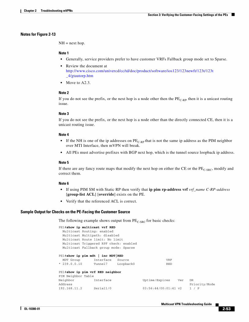
Chapter 2 Troubleshooting mVPNs Section 3: Verifying the Customer-Facing Settings of the PEs
Notes for Figure 2-13
NH = next hop.
Note 1
• Generally, service providers prefer to have customer VRFs Fallback group mode set to Sparse.
• Review the document at http://www.cisco.com/univercd/cc/td/doc/product/software/ios123/123newft/123t/123t _4/gtautorp.htm
• Move to A2.3.
Note 2
If you do not see the prefix, or the next hop is a node other then the PEC-RP, then it is a unicast routing issue.
Note 3
If you do not see the prefix, or the next hop is a node other than the directly connected CE, then it is a unicast routing issue.
Note 4
• If the NH is one of the ip addresses on PEC-RP that is not the same ip address as the PIM neighbor over MTI Interface, then mVPN will break.
• All PEs must advertise prefixes with BGP next hop, which is the tunnel source loopback ip address.
Note 5
If there are any fancy route maps that modify the next hop on either the CE or the PEC-SRC, modify and correct them.
Note 6
• If using PIM SM with Static RP then verify that ip pim rp-address vrf vrf_name C-RP-address [group-list ACL] [override] exists on the PE.
• Verify that the referenced ACL is correct.
Sample Output for Checks on the PE-Facing the Customer Source
The following example shows output from PEC-SRC for basic checks:
PE1#show ip multicast vrf RED Multicast Routing: enabled Multicast Multipath: disabled Multicast Route limit: No limit Multicast Triggered RPF check: enabled Multicast Fallback group mode: Sparse
PE1#show ip pim mdt | inc MDT|RED MDT Group Interface Source VRF* 239.0.0.10 Tunnel7 Loopback0 RED
PE1#show ip pim vrf RED neighborPIM Neighbor TableNeighbor Interface Uptime/Expires Ver DRAddress Priority/Mode192.168.11.2 Serial1/0 03:56:44/00:01:41 v2 1 / P
2-53Multicast VPN Troubleshooting Guide
OL-10380-01

Chapter 2 Troubleshooting mVPNs Section 3: Verifying the Customer-Facing Settings of the PEs
172.16.100.2 Tunnel7 03:59:21/00:01:35 v2 1 / P172.16.100.3 Tunnel7 03:59:21/00:01:25 v2 1 / DR P
PE1#show ip pim vrf RED interface S1/0 detail Serial1/0 is up, line protocol is up Internet address is 192.168.11.1/24 Multicast switching: fast Multicast packets in/out: 1967476/1928 Multicast boundary: not set Multicast TTL threshold: 0 PIM: enabled PIM version: 2, mode: sparse PIM DR: 0.0.0.0 PIM neighbor count: 1 PIM Hello/Query interval: 30 seconds PIM NBMA mode: disabled PIM ATM multipoint signalling: disabled PIM domain border: disabled PIM neighbors rpf proxy capable: TRUE Multicast Tagswitching: disabled
PE1#show ip rpf vrf RED 192.168.100.202 C-RPRPF information for ? (192.168.100.202) RPF interface: Tunnel7 RPF neighbor: ? (172.16.100.2) RPF route/mask: 192.168.100.202/32 RPF type: unicast (bgp 1) RPF recursion count: 0 Doing distance-preferred lookups across tables BGP originator: 172.16.100.2
PE1#show ip rpf vrf RED 192.168.1.1 C-SrcRPF information for ? (192.168.1.1) RPF interface: Serial1/0 RPF neighbor: ? (192.168.11.2) RPF route/mask: 192.168.1.0/24 RPF type: unicast (bgp 1) RPF recursion count: 1 Doing distance-preferred lookups across tables
After the above is verified, check the RP mapping on the PEC-SRC. Also, verify that the ACL referenced is not misconfigured.
• Static RP Mapping
If the customer is running static RP, verify that all the PEs in the mVRF are configured with the correct static RP:
ip pim rp-address rp-address [group_acl] [override]
It is recommended to use the override keyword to override the dynamically learned RP mappings. Also, verify that the value specified by group_acl is correctly configured in the ACL and correctly referenced in the above command.
• AutoRP Mapping Using Cisco AutoRP
For AutoRP, verify the following:
– PEC-SRC learns the RP mapping from the PEC-RP over the MTI
– PEC-SRC advertises the RP mapping to the directly connected CEs
The flowchart in Figure 2-14 walks through the essential configurations for AutoRP on the PEC-SRC.
2-54Multicast VPN Troubleshooting Guide
OL-10380-01

Chapter 2 Troubleshooting mVPNs Section 3: Verifying the Customer-Facing Settings of the PEs
Figure 2-14 AutoRP Troubleshooting on PEC-SRC
Y e sY e s
I s A u t o R P l i s t e n e r c o n f i g u r e d f o r t h i s V R F ?S e e N o t e 1 f o r t h e c h e c k in g p r o c e d u r e N o
C o n f i g u r e i p p i m v r f< v r f _ n a m e > a u t o r pl i s t e n e r
E i t h e r c o n f i g u r e a l l P E - C E in t e r f a c e s i n P I M s p a r s e -d e n s e m o d eo r e n a b le A u t o R P l i s t e n e r .R e a d n o t e 2
I s t h e r e a n y m u l t i c a s t b o u n d a r ys t a t e m e n t c o n f i g u r e d o n t h e P E - C Ein t e r f a c e ( s ) ?
Y e s
I s t h e A C L b lo c k in g t h e A u t o R P g r o u p s ?
N o
U s e d e b u g i p p i m v r f < v r f _ n a m e > a u t o r pW a i t f o r 6 0 - 9 0 s e c s .A r e y o u g e t t i n g a n y A u t o R P m e s s a g e s ?S e e N o t e 5
U s e s h o w i p p i m n e i g h b o r v r f< v r f _ n a m e >D o y o u s e e P E C - R P a P I M n e ig h b o r o v e r t h eM T I i n t e r f a c e ?
Y e s
R e c o n f i g u r e t h e A C L t o a l l o w t h eA u t o R P g r o u p s . R e t u r n t o A 2 . 7
U s e s h o w i p p i m v r f < v r f _ n a m e >in t e r f a c eA r e a l l P E - C E in t e r f a c e s e n a b le d f o rP I M S p a r s e M o d e o n l y ?
N o
N o Y e sU s e s h o w i p p i m v r f< v r f _ n a m e > r p m a p p in gI s t h e r e a R P c o v e r i n g t h eC u s t o m e r m u l t i c a s t a d d r e s sr a n g e ?
I s t h i s t h ec o r r e c t R P ?
Y e s
A 2 . 7
R e p o r t t o t h e c u s t o m e rR e a d N o t e 4R e t u r n t o A 2 . 7
V e r i f y t h a t t h e M D TT u n n e l i n t e r f a c e i s i n t h eI I L o f ( S , G ) e n t r y f o r2 2 4 . 0 . 1 . 4 0 a n d2 2 4 . 0 . 1 . 3 9 .S e e T a b le 2
N o
A r e a l l t h e P E - C E in t e r f a c e sc o n f i g u r e d f o r P I M s p a r s e - d e n s em o d e ?
N o R e t u r n t oA 2 . 7
Y e s
Y e s
N o
N o
C o n t a c t C i s c o T A C
Y e s
N o
G o b a c k t o “ S e c t i o n 5B a s i c c h e c k o n P E C -
S r c “ ( F i g u r e 2 - 1 3 )
E n s u r e t h a t w e s e eP E C - R P a s a P I Mn e ig h b o r .R e t u r n t o A 2 . 7
N o
Y e s
V e r i f y t h a t t h e P E C - R P h a s t h e M T I I n t e r f a c e i n t h e O I L i n s h o w i p m r o u t e v r f< v r f _ n a m e > 2 2 4 . 0 . 1 . 4 0 . O p e n T A C c a s e i f t h e p r o b le m s t i l l e x i s t s
U s e s h o w i p r f v r f< v r f _ n a m e > < R P - a d d r e s s > - - V e r i f y t h a t R P F in t e r f a c e i s a T u n n e l I n t e r f a c e - - R P F n e ig h b o r i s P E C - R P
Y e s
M o v e t o t h e F ig u r e2 - 1 5 i n s e c t i o n“ B a s i c c h e c k o nP E C - R C V R ”
S t a r t
2-55Multicast VPN Troubleshooting Guide
OL-10380-01
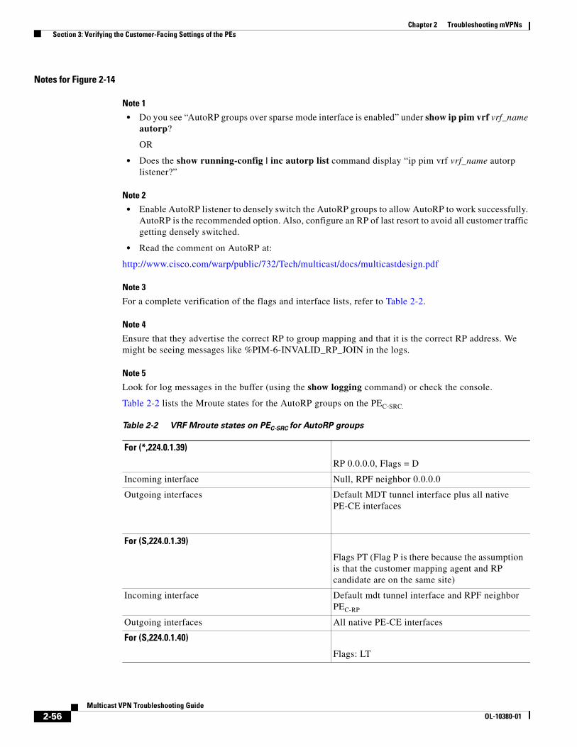
Chapter 2 Troubleshooting mVPNs Section 3: Verifying the Customer-Facing Settings of the PEs
Notes for Figure 2-14
Note 1
• Do you see “AutoRP groups over sparse mode interface is enabled” under show ip pim vrf vrf_name autorp?
OR
• Does the show running-config | inc autorp list command display “ip pim vrf vrf_name autorp listener?”
Note 2
• Enable AutoRP listener to densely switch the AutoRP groups to allow AutoRP to work successfully. AutoRP is the recommended option. Also, configure an RP of last resort to avoid all customer traffic getting densely switched.
• Read the comment on AutoRP at:
http://www.cisco.com/warp/public/732/Tech/multicast/docs/multicastdesign.pdf
Note 3
For a complete verification of the flags and interface lists, refer to Table 2-2.
Note 4
Ensure that they advertise the correct RP to group mapping and that it is the correct RP address. We might be seeing messages like %PIM-6-INVALID_RP_JOIN in the logs.
Note 5
Look for log messages in the buffer (using the show logging command) or check the console.
Table 2-2 lists the Mroute states for the AutoRP groups on the PEC-SRC.
Table 2-2 VRF Mroute states on PEC-SRC for AutoRP groups
For (*,224.0.1.39)
RP 0.0.0.0, Flags = D
Incoming interface Null, RPF neighbor 0.0.0.0
Outgoing interfaces Default MDT tunnel interface plus all native PE-CE interfaces
For (S,224.0.1.39)
Flags PT (Flag P is there because the assumption is that the customer mapping agent and RP candidate are on the same site)
Incoming interface Default mdt tunnel interface and RPF neighbor PEC-RP
Outgoing interfaces All native PE-CE interfaces
For (S,224.0.1.40)
Flags: LT
2-56Multicast VPN Troubleshooting Guide
OL-10380-01
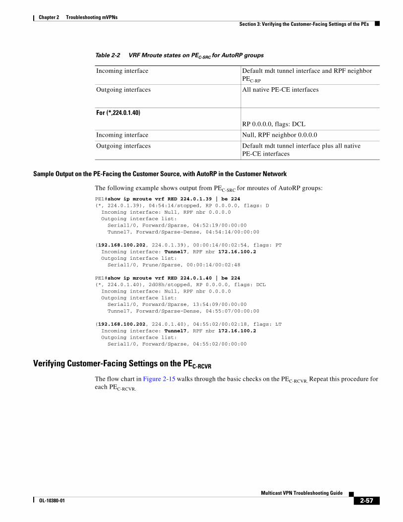
Chapter 2 Troubleshooting mVPNs Section 3: Verifying the Customer-Facing Settings of the PEs
Sample Output on the PE-Facing the Customer Source, with AutoRP in the Customer Network
The following example shows output from PEC-SRC for mroutes of AutoRP groups:
PE1#show ip mroute vrf RED 224.0.1.39 | be 224(*, 224.0.1.39), 04:54:14/stopped, RP 0.0.0.0, flags: D Incoming interface: Null, RPF nbr 0.0.0.0 Outgoing interface list: Serial1/0, Forward/Sparse, 04:52:19/00:00:00 Tunnel7, Forward/Sparse-Dense, 04:54:14/00:00:00
(192.168.100.202, 224.0.1.39), 00:00:14/00:02:54, flags: PT Incoming interface: Tunnel7, RPF nbr 172.16.100.2 Outgoing interface list: Serial1/0, Prune/Sparse, 00:00:14/00:02:48
PE1#show ip mroute vrf RED 224.0.1.40 | be 224(*, 224.0.1.40), 2d08h/stopped, RP 0.0.0.0, flags: DCL Incoming interface: Null, RPF nbr 0.0.0.0 Outgoing interface list: Serial1/0, Forward/Sparse, 13:54:09/00:00:00 Tunnel7, Forward/Sparse-Dense, 04:55:07/00:00:00
(192.168.100.202, 224.0.1.40), 04:55:02/00:02:18, flags: LT Incoming interface: Tunnel7, RPF nbr 172.16.100.2 Outgoing interface list: Serial1/0, Forward/Sparse, 04:55:02/00:00:00
Verifying Customer-Facing Settings on the PEC-RCVR
The flow chart in Figure 2-15 walks through the basic checks on the PEC-RCVR. Repeat this procedure for each PEC-RCVR.
Incoming interface Default mdt tunnel interface and RPF neighbor PEC-RP
Outgoing interfaces All native PE-CE interfaces
For (*,224.0.1.40)
RP 0.0.0.0, flags: DCL
Incoming interface Null, RPF neighbor 0.0.0.0
Outgoing interfaces Default mdt tunnel interface plus all native PE-CE interfaces
Table 2-2 VRF Mroute states on PEC-SRC for AutoRP groups
2-57Multicast VPN Troubleshooting Guide
OL-10380-01

Chapter 2 Troubleshooting mVPNs Section 3: Verifying the Customer-Facing Settings of the PEs
Figure 2-15 Troubleshooting Guidelines for PEC-RCVR.
U s e s h o w i p p i m m d t | i n c < v r f n a m e > O r s h o wi p p i m m d tD o y o u s e e t h e M T I f o r t h e c u s t o m e r ’ s V R F ?E n s u r e t h e M D T g r o u p i s c o r r e c t .
N o
U s e s h o w i p p i m v r f < v r f _ n a m e > n e i g h b o r
D o y o u s e e P E C - R P a n d P E C - S R C a s P I Mn e i g h b o r s o v e r M D T t u n n e l i n t e r f a c e ? N o
D o y o u s e e a l l e x p e c t e d P E - C E P I M n e i g h b o r s ?N o
A p p l y S e c t i o n 3 : ” T r o u b l e s h o o t i n g P I M n e i g h b o r s o v e rP E - C E I n t e r f a c e ”A f t e r c o m p l e t i o n r e t u r n t o A 3 . 1
A p p l y S e c t i o n 2 : “ C h e c k i n g t h e P I M n e i g h b o r s h i pi n f o r m a t i o n o n a s p e c i f i c P E ”A f t e r c o m p l e t i o n r e t u r n t o A 3 . 1
A p p l y S e c t i o n 2 : “ T r o u b l e s h o o t i n g t h e M T I I n t e r f a c es t a t u s a n d B G P s e t t i n g s o n a s p e c i f i c P E ”A f t e r c o m p l e t i o n , r e t u r n t o A 3 . 0
A 3 . 0
A 3 . 1
Y e s
Y e s
Y e s
U s e s h o w i p m u l t i c a s t v r f < v r f _ n a m e >I s M u l t i c a s t R o u t i n g e n a b l e d ?
U s e s h o w i p p i m v r f < v r f _ n a m e > i n t e r f a c e c o u n tD o y o u s e e t h e F a s t S w i t c h i n g F l a g u n d e r e a c h i n t e r f a c e ?
C o n f i g u r e i p m u l t i c a s t - r o u t i n g v r f < v r f _ n a m e >R e t u r n t o A 3 . 2
A 3 . 2N o
A 3 . 3
N o C o n f i g u r e i p m r o u t e - c a c h e u n d e r a l l n a t i v e P E - C E i n t e r f a c e s .R e t u r n t o A 3 . 3
U s e s h o w i p m u l t i c a s t v r f < v r f _ n a m e >I s M u l t i c a s t F a l l b a c k g r o u p m o d e s e t t o S p a r s e ?
Y e s
N o S e e N o t e 1C o n f i g u r e n o i p p i m v r f < v r f _ n a m e > d m - f a l l b a c kM o v e t o A 3 . 3
U s e s h o w i p r p f v r f < v r f _ n a m e > < C - R P >D o y o u s e e a n e r r o r m e s s a g e s a y i n g “ R P Fi n f o r m a t i o n f o r < C - R P > f a i l e d , n o r o u t ee x i s t s ” ?
U s e s h o w i p r o u t e v r f < v r f _ n a m e > < C - R P >N o t e t h e N H . I s P E C - R P t h e N H f o r t h e R o u t e ?
S e e N o t e 2 .F i x t h e u n i c a s t r o u t i n gi s s u eR e t u r n t o A 3 . 4
N oY e s
A 3 . 4
Y e s
A l l P E s m u s t a d v e r t i s ep r e f i x e s w i t h B G P N Hw h i c h i s t h e i r T u n n e lS o u r c e I P a d d r e s s .S e e N o t e 4F i x t h e i s s u e o n P E C - R PR e t u r n t o A 3 . 4
I s t h e N H t h e s a m e I P a d d r e s s t h a ty o u p e e r w i t h i n s h o w i p p i m v r f< v r f _ n a m e > n e i g h b o r ?
N o
C o n t a c t C i s c o T A C Y e sN o
V e r i f y t h a t : - - R P F n e i g h b o r i s P E C - R P - - R P F i n t e r f a c e i s t h e M T I
U s e s h o w i p r p f v r f < v r f _ n a m e > < C - S r c > : D o y o u s e e a n e r r o r m e s s a g es a y i n g “ R P F i n f o r m a t i o n f o r < C - S r c > f a i l e d , n o r o u t e e x i s t s ” ?
A 3 . 5 U s e s h o w i pr o u t e v r f< v r f _ n a m e > < C -S R C > I s P E C - S r c t h e N Hf o r t h e R o u t e ?
Y e s
Y e s
A l l P E s m u s t a d v e r t i s e p r e f i x e s w i t hB G P N H w h i c h i s t h e i r T u n n e l S o u r c eI P a d d r e s s . S e e N o t e 5F i x t h e i s s u e o n P E C - S r cR e t u r n t o A 3 . 5
I s t h e N H t h e s a m e I P a d d r e s s a s t h e o n e t h e l o c a lP E p e e r s w i t h i n s h o w i p p i m v r f < v r f _ n a m e >n e i g h b o r ?
C o n t a c t C i s c o T A C
Y e s
. i t i s p r o b a b l y a u n i c a s tr o u t i n g i s s u e ; S e e N o t e 3 .F i x t h e i s s u eR e t u r n t o A 3 . 5
N o
N o
V e r i f y t h a t : - - R P F n e i g h b o r i s P E C - S R C - - R P F i n t e r f a c e i s t h e M T I
N o
M o v e t o ” P E C - R C V R A u t o R P C h e c k ” ( F i g u r e 2 - 1 6 )
S t a t i c R P
I s t h e r e a n y m u l t i c a s t b o u n d a r y s t a t e m e n t c o n f i g u r e do n a n y o f t h e n a t i v e P E - C E i n t e r f a c e s ?
I s t h e A C L b l o c k i n g t h e C - G P A r a n g e ?
Y e s
Y e s
A 3 . 6
A u t o R PR e c o n f i g u r e t h e A C L t o a l l o w t h e C - G P A r a n g e . R e t u r n t o A 3 . 6
I f u s i n g P I M S M w i t h S t a t i c R P t h e nv e r i f y t h a ti p p i m r p - a d d r e s s v r f < v r f _ n a m e >< C - R P - a d d r e s s > [ g r o u p - l i s t A C L ][ o v e r r i d e ] e x i s t s o n t h e P E , w i t h ap r o p e r A C L
N o
N oW h a t i s t h e R P
E l e c t i o n m e c h a n i s mf o r t h i s c u s t o m e r ?
2-58Multicast VPN Troubleshooting Guide
OL-10380-01

Chapter 2 Troubleshooting mVPNs Section 3: Verifying the Customer-Facing Settings of the PEs
Notes for Figure 2-15
NH = Next hop.
Note 1
Generally, service providers prefer to have customer VRFs Fallback group mode to Sparse
• Read the document at
http://www.cisco.com/univercd/cc/td/doc/product/software/ios123/123newft/123t/123t_4/gtautorp.htm
• Move to A3.3.
Note 2
If you do not see the prefix or the next hop is a node other then the PEC-RP then it is a unicast routing issue
Note 3
If you do not see the prefix, or the next hop is a node other than the PEC-SRC, then it is a unicast routing issue.
Note 4
If the NH (from the show ip route vrf vrf_name C-SRC command) is one of the IP addresses on PEC-RP that is not the same IP address as the PIM neighbor over the MTI Interface, then mVPN will break.
Note 5
If the NH (from the show ip route vrf vrf_name C-SRC command) is one of the IP addresses on PEC-SRC that is not the same ip address as the PIM neighbor over MTI Interface, then mVPN will break.
Sample Output for the PEs Facing one or more Customer Receivers
The following example shows output from PEC-RCVR for basic checks:
PE3#show ip multicast vrf RED Multicast Routing: enabled Multicast Multipath: disabled Multicast Route limit: No limit Multicast Triggered RPF check: enabled Multicast Fallback group mode: Sparse
PE3#show ip pim mdt | inc MDT|RED MDT Group Interface Source VRF* 239.0.0.10 Tunnel0 Loopback0 RED
PE3#show ip pim vrf RED neighbor PIM Neighbor TableNeighbor Interface Uptime/Expires Ver DRAddress Priority/Mode192.168.33.2 Serial1/0 2d09h/00:01:34 v2 1 / P172.16.100.1 Tunnel0 04:56:48/00:01:16 v2 1 / P172.16.100.2 Tunnel0 2d09h/00:01:19 v2 1 / P
PE3#show ip pim vrf RED interface Serial 1/0 detail Serial1/0 is up, line protocol is up Internet address is 192.168.33.1/24 Multicast switching: fast Multicast packets in/out: 0/344922 Multicast boundary: not set
2-59Multicast VPN Troubleshooting Guide
OL-10380-01

Chapter 2 Troubleshooting mVPNs Section 3: Verifying the Customer-Facing Settings of the PEs
Multicast TTL threshold: 0 PIM: enabled PIM version: 2, mode: sparse PIM DR: 0.0.0.0 PIM neighbor count: 1 PIM Hello/Query interval: 30 seconds PIM NBMA mode: disabled PIM ATM multipoint signalling: disabled PIM domain border: disabled PIM neighbors rpf proxy capable: TRUE Multicast Tagswitching: disabled
PE3#show ip rpf vrf RED 192.168.100.202 C-RPRPF information for ? (192.168.100.202) RPF interface: Tunnel0 RPF neighbor: ? (172.16.100.2) RPF route/mask: 192.168.100.202/32 RPF type: unicast (bgp 1) RPF recursion count: 0 Doing distance-preferred lookups across tables BGP originator: 172.16.100.2
PE3#show ip rpf vrf RED 192.168.1.1 C-SrcRPF information for ? (192.168.1.1) RPF interface: Tunnel0 RPF neighbor: ? (172.16.100.1) RPF route/mask: 192.168.1.0/24 RPF type: unicast (bgp 1) RPF recursion count: 0 Doing distance-preferred lookups across tables BGP originator: 172.16.100.1
After the above is verified, check the RP mapping on PEC-RCVR.
• Static RP Mapping
If the customer is running static RP, verify that all the PEs in the mVRF are configured with the correct static RP:
ip pim rp-address rp-address [group_acl] [override]
It is recommended to use the override keyword to override the dynamically learned RP mappings. Also verify that the value specified by group_acl is correctly configured in the ACL and correctly referenced in the above command.
• AutoRP Mapping using Cisco AutoRP
For AutoRP, verify the following:
– PEC-RCVR learns the RP mapping from the PEC-RP over the MTI
– Advertises the RP mapping to the directly connected CEs
The flowchart in Figure 2-16 walks through the essential AutoRP configurations on the PEC-RCVR.
2-60Multicast VPN Troubleshooting Guide
OL-10380-01

Chapter 2 Troubleshooting mVPNs Section 3: Verifying the Customer-Facing Settings of the PEs
Figure 2-16 AutoRP Troubleshooting Guidelines on PE-C-RVCR
Y e sY e s
Is A u to R P lis te n e r c o n fig u re d fo r th is V R F ?C h e c k u s in g N o te 1 N o
C o n fig u re ip p im v r f< v r f_ n a m e > a u to r p l is te n e r
E ith e r c o n f ig u re a ll P E -C E in te r fa c e s in P IM s p a rs e -d e n s e m o d eO R e n a b le A u to R P lis te n e r to a llo w A u to R P to w o rks u c c e s s fu lly .A ls o c o n f ig u re a la s t re s o r t R P : s e e n o te 2
D o w e h a v e a n y m u lt ic a s t b o u n d a r y s ta te m e n tc o n f ig u re d o n th e P E -C E in te r fa c e (s )?
Y e s
Is th e A C L b lo c k in g th e A u to R P g ro u p s ?
N oU s e d e b u g ip p im v r f < v r f_ n a m e > a u to r p a n d w a it fo r6 0 -9 0 s e c s . A re y o u g e tt in g a n y A u to R P m e s s a g e su n d e r s h o w lo g o r c o n s o le s e s s io n ?
U s e s h o w ip p im n e ig h b o r v r f< v r f_ n a m e >D o y o u s e e P E C -R P a P IM n e ig h b o r o v e r th e M T Iin te r fa c e ?
Y e s
R e c o n fig u re th e A C L to a llo w th e A u to R Pg ro u p s . R e tu rn to A 3 .7
U s e s h o w ip p im v r f < v r f_ n a m e > in te r fa c eA re a ll P E -C E in te r fa c e s e n a b le d fo r P IMs p a rs e m o d e o n ly ?
N o
N oY e sU s e s h o w ip p im v r f < v r f_ n a m e > r p m a p p in g
D o y o u s e e a n R P a d d re s s c o v e r in g th eC u s to m e r G P A ra n g e ?
Is th is th ec o r re c t R P ?Y e s
A 3 .7
V e r ify th a t th e M T I is in th e I IL o f (S ,G ) e n t r y fo r2 2 4 .0 .1 .4 0 a n d 2 2 4 .0 .1 .3 9.R e a d T a b le 3
N o
A re a ll P E -C E in te r fa c e s c o n f ig u re d fo rP IM s p a rs e -d e n s e m o d e ?
N o
R e tu rn toA 3 .7
Y e s
Y e s
N o
N o
C o n ta c tC is c o T A CY e s
S ta r t
N o
G o b a c k to “ S e c t io n 5 B a s ic c h e c k o nP E C -R C V R “ (F ig u r e 2 -1 5 ) .E n s u re th a t w e s e e P E C -R P a s a P IMn e ig h b o r .R e tu rn to A 3 .7
N o
Y e s
V e r ify th a t th e P E C -R P h a s th e M T I In te r fa c e in th e O IL in s h o w ip m r o u tev r f < v r f_ n a m e > 2 2 4 .0 .1 .4 0 ” .O p e n a T A C c a s e if th e p ro b le m s t i l l e x is ts
R e p o r t to th e c u s to m e r a n d e n s u re th e y a d v e r t is e th ec o r re c t R P - to -g ro u p m a p p in g a n d w e a re in s y n c w ith th ec o r re c t R P a d d re s s .R e a d N o te 3R e tu rn to A 3 .7
M o v e to th e F ig u r e 2 -1 7
2-61Multicast VPN Troubleshooting Guide
OL-10380-01

Chapter 2 Troubleshooting mVPNs Section 3: Verifying the Customer-Facing Settings of the PEs
Notes for Figure 2-16
Note 1
• Do you see “AutoRP groups over sparse mode interface is enabled” under show ip pim vrf vrf_name autorp?
OR
• Does show running-config | inc autorp list display “ip pim vrf vrf_name autorp listener?”
Note 2
• Last resort RP will avoid all customer traffic getting densely switched.
• Read the comment on Auto-RP at
http://www.cisco.com/warp/public/732/Tech/multicast/docs/multicastdesign.pdf
Note 3
We might be seeing messages like %PIM-6-INVALID_RP_JOIN in the logs.
Sample Output on the PEC-RCVR for Mroutes of AutoRP Groups
PE3#show ip mroute vrf RED 224.0.1.39 | be 224(*, 224.0.1.39), 2d09h/stopped, RP 0.0.0.0, flags: D
Table 2-3 VRF Mroute states on PEC-RCVR for AutoRP groups
For (*,224.0.1.39)
RP 0.0.0.0, Flags = D
Incoming interface Null, RPF neighbor 0.0.0.0
Outgoing interfaces Default mdt tunnel interface plus all native PE-CE interfaces
For (S,224.0.1.39)
Flags PT (flag P is there because the assumption is that the customer mapping agent and RP candidate are on the same site)
Incoming interface Default mdt tunnel interface and RPF neighbor PEC-RP
Outgoing interfaces All native PE-CE interfaces
For (*,224.0.1.40)
RP 0.0.0.0, flags: DCL
Incoming interface Null, RPF neighbor 0.0.0.0
Outgoing interfaces Default mdt tunnel interface plus all native PE-CE interfaces
For (S,224.0.1.40)
Flags: LT
Incoming interface Default mdt tunnel interface and RPF neighbor PEC-RP
Outgoing interfaces All native PE-CE interfaces
2-62Multicast VPN Troubleshooting Guide
OL-10380-01

Chapter 2 Troubleshooting mVPNs Section 3: Verifying the Customer-Facing Settings of the PEs
Incoming interface: Null, RPF nbr 0.0.0.0 Outgoing interface list: Serial1/0, Forward/Sparse, 2d09h/00:00:00 Tunnel0, Forward/Sparse-Dense, 2d09h/00:00:00
(192.168.100.202, 224.0.1.39), 00:03:24/00:00:10, flags: PT Incoming interface: Tunnel0, RPF nbr 172.16.100.2 Outgoing interface list: Serial1/0, Prune/Sparse, 00:03:24/00:00:09
PE3#show ip mroute vrf RED 224.0.1.40 | be 224(*, 224.0.1.40), 2d09h/stopped, RP 0.0.0.0, flags: DCL Incoming interface: Null, RPF nbr 0.0.0.0 Outgoing interface list: Serial1/0, Forward/Sparse, 2d09h/00:00:00 Tunnel0, Forward/Sparse-Dense, 2d09h/00:00:00
(192.168.100.202, 224.0.1.40), 2d09h/00:02:50, flags: LT Incoming interface: Tunnel0, RPF nbr 172.16.100.2 Outgoing interface list: Serial1/0, Forward/Sparse, 2d09h/00:00:00
Verifying Consistency of the Customer RP Settings
After the individual PEs have been checked, verify that the RP mapping is consistent across all PEs involved.
Verifying the Multicast Routes on the PEs in the VRF Context
This section describes how to check the customer-specific Mroute states on the PEs.
Here is a high level description of the steps:
• Start by checking the (*,C-GPA) entry on PEC-RP.
• If the (*,C-GPA) entry does not exists on PEC-RP, check the PEC-RCVR to verify that it has received the PIM joins from the CE and has forwarded them to the PEC-RP.
• After the (*,C-GPA) entry is verified with Table 2-4, check the (C-SRC, C-GPA) entry on PEC-RP, PEC-SRC and all the PEC-RCVR.
The flowchart in Figure 2-17 provides the step-by-step procedure for troubleshooting this aspect of the control plane.
2-63Multicast VPN Troubleshooting Guide
OL-10380-01

Chapter 2 Troubleshooting mVPNs Section 3: Verifying the Customer-Facing Settings of the PEs
Figure 2-17 Troubleshooting Guidelines for the Control Plane
O n P E C - R P e n t e r s h o w i p m r o u t ev r f < v r f _ n a m e > < C - G P A >D o y o u s e e t h e ( * , G P A ) e n t r y ?
A 4 . 1
I s t h e M T I T u n n e l I n t e r f a c e i n t h eO I L o f t h e ( * , G P A ) ?
N o
Y e s
V e r i f y t h e f o l l o w i n g :- - I n c o m i n g I n t e r f a c e ( P E - C E i n t e r f a c e )- - R P F n b r ( C E ) ; s e e T a b l e 4 f o r d e t a i l s
Y e s
O n P E C - R P e n t e r s h o w i p m r o u t e v r f< v r f _ n a m e > < C - G P A >D o y o u s e e t h e ( C - S r c , G P A ) e n t r y ?
A 4 . 2
G o t o F i g u r e 2 - 1 8
N o
O b t a i n a n o u t p u t w i t hs h o w i p m r o u t e < G P A >
o n C - R P
I s t h e r e a( * , G P A )e n t r y ?
Y e sI s t h e O I L
e m p t y f o r t h e( * , G P A ) ?
T h i s i s p r o b a b l y a c u s t o m e r - s i d e i s s u e ( s e eN o t e 1 ) . V e r i f y h o p - b y - h o p i n t h e c u s t o m e rn e t w o r k t h a t t h e y a r e g e t t i n g P I M ( * , G ) j o i n s
N o
Y e s
I s t h e r e a ( C - S r c ,G P A ) e n t r y o nC - R P ?
N oY e s
V e r i f y , o n t h e ( C - S r c , G P A ) e n t r y o n t h e P E C - R P :I I L = M T I I n t e r f a c e w i t h P E C - S R C a s t h e R P F n b rO I L = N u l lS e e T a b l e 4 f o r d e t a i l . G o t o A 4 . 3
O n P E C - R P , i s t h e r e a “ R ” f l a g o n ( C -S r c , G P A ) e n t r y ?
Y e s
O n P E C - S R C u s e s h o w i p m r o u t e v r f< v r f _ n a m e > < C - G P A >D o y o u s e e t h e ( C - S r c , G P A ) e n t r y ?
Y e s
V e r i f y h o p - b y - h o pi n t h e c u s t o m e rn e t w o r k t h a t P I M( C - S r c , G P A ) j o i n sa r e s e n t t o P E C - R P
V e r i f y t h a t s o u r c e i se m i t t i n g t r a f f i c w i t hp r o p e r T T L . I s t h e f i r s th o p r o u t e r s t u c k i nr e g i s t e r i n g ?
F i x a n y i s s u e a n dR e t u r n t o A 4 . 2
N o
V e r i f y t h a t t h e M T I i s i n t h e O I L .U s e T a b l e 5 f o r d e t a i l .
Y e s
V e r i f y , o n t h e ( C - S r c , G P A ) e n t r y o n t h e P E C - R P :I I L = P E - C E I n t e r f a c e t o w a r d s C - R PO I L = N u l lS e e T a b l e 4 f o r d e t a i l s . G o t o A 4 . 3
N oA 4 . 3
N o
I t c o u l d b e n o r m a l , s e e N o t e 2V e r i f y t h i s w i t h t h e c u s t o m e rY e s
O n P E C - R C V R e n t e r s h o w i pm r o u t e v r f < v r f _ n a m e > < C -G P A >D o y o u s e e t h e ( C - S r c , G P A )e n t r y ?
A 4 . 4
V e r i f y t h e ( C - S r c , G P A ) e n t r y o n P E C - R C V RI I L = M T I I n t e r f a c e w i t h P E C - S R C a s t h e R P F n b rO I L = P E - C E I n t e r f a c e w h e r e t h e ( * , G P A ) j o i n s a r e c o m i n g f r o mS e e T a b l e 6 f o r d e t a i l s .
O n P E C - R P e n t e r d e b u g i pp i m v r f < v r f _ n a m e > < C - G P A >I s t h e P E C - R P r e c e i v i n g a n y“ P I M j o i n s ” o r i g i n a t e d f r o m t h eC - R , P t o j o i n t h e s o u r c e p a t ht r e e ?
Y e s
O p e n a T A C c a s e
N o
E n t e r d e b u g i p p i m v r f < v r f _ n a m e > < C - G P A > , o nP E C - S r c & P E C - R P .
V e r i f y t h e f o l l o w i n g :- - P E C - R P i s s e n d i n g ( S , G ) j o i n s- - P E C - S r c i s r e c e i v i n g ( S , G ) P I M j o i n s f r o m P E C - R P o rP E C - R C V R .
N o
I f y o u s t i l l d o n o t s e e t h ee n t r y f o r ( C - S r c , G P A )o n P E C - S R C , C o n t a c tC i s c o T A C .
M o v e t o S e c t i o n 4
2-64Multicast VPN Troubleshooting Guide
OL-10380-01
Chapter 2 Troubleshooting mVPNs Section 3: Verifying the Customer-Facing Settings of the PEs
Notes for Figure 2-17
Note 1
This is probably a customer issue. The C-RP has not received the PIM (*,GPA) join from the PEC-RP.
Note 2
This would be normal if the last hop router (normally a C or CE router closest to the receiver IGMP host) was configured with a finite SPT threshold value, and the traffic received on the shared tree was below the threshold value.
Note In Figure 2-17, if (*,C-GPA) entry is not present on PEC-RP, the flowchart in Figure 2-18 can be used to further troubleshoot the control plane.
2-65Multicast VPN Troubleshooting Guide
OL-10380-01
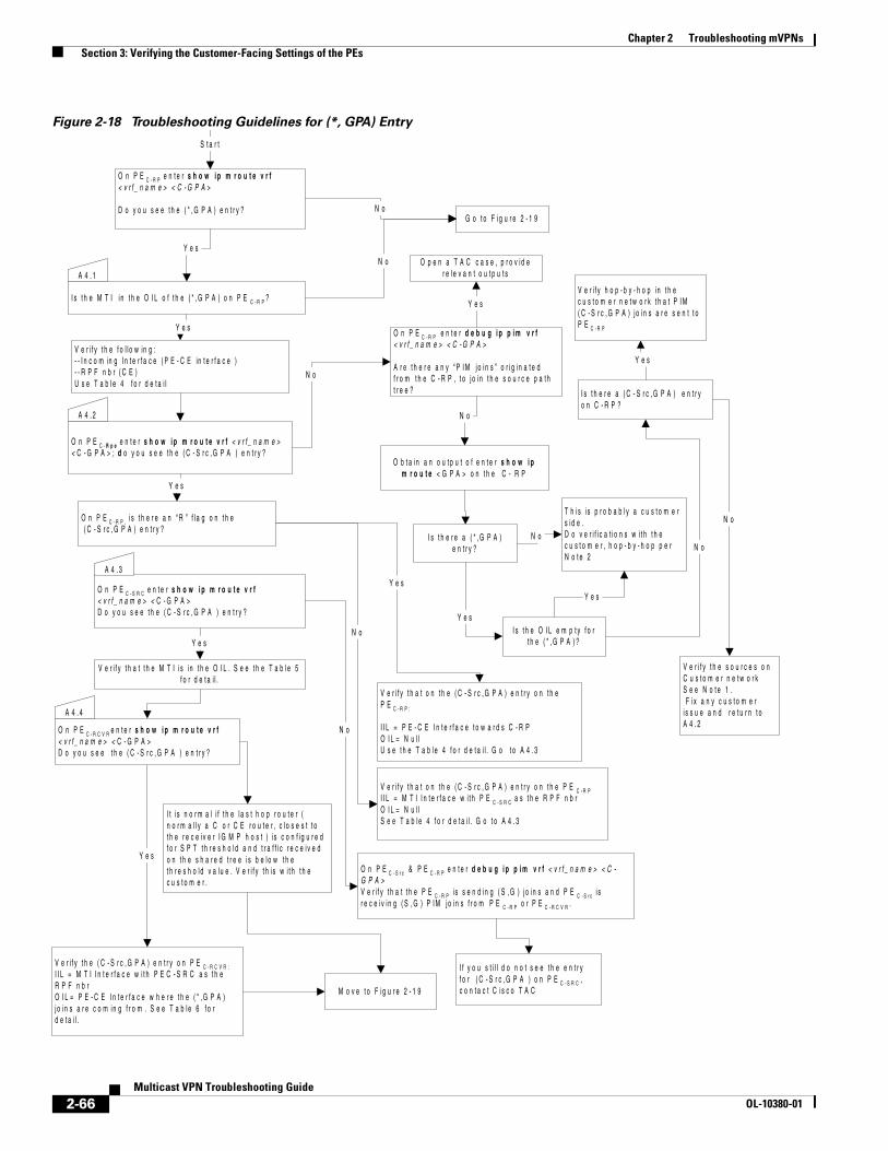
Chapter 2 Troubleshooting mVPNs Section 3: Verifying the Customer-Facing Settings of the PEs
Figure 2-18 Troubleshooting Guidelines for (*, GPA) Entry
S t a r t
O n P E C - R P e n t e r s h o w i p m r o u t e v r f< v r f _ n a m e > < C - G P A >
D o y o u s e e t h e ( * , G P A ) e n t r y ? N o
A 4 . 1
I s t h e M T I i n t h e O I L o f t h e ( * , G P A ) o n P E C - R P ?
N oY e s
V e r i f y t h e f o l l o w in g :- - I n c o m i n g I n t e r f a c e ( P E - C E in t e r f a c e )- - R P F n b r ( C E )U s e T a b l e 4 f o r d e t a i l
Y e s
O n P E C - R p e e n t e r s h o w i p m r o u t e v r f < v r f _ n a m e >< C - G P A > ; d o y o u s e e t h e ( C - S r c , G P A ) e n t r y ?
A 4 . 2
G o t o F i g u r e 2 - 1 9
N o
O b t a i n a n o u t p u t o f e n t e r s h o w i pm r o u t e < G P A > o n t h e C - R P
I s t h e r e a ( * , G P A )e n t r y ?
Y e sI s t h e O I L e m p t y f o r
t h e ( * , G P A ) ?
T h i s i s p r o b a b l y a c u s t o m e rs i d e .D o v e r i f i c a t i o n s w i t h t h ec u s t o m e r , h o p - b y - h o p p e rN o t e 2
N o
Y e s
I s t h e r e a ( C - S r c , G P A ) e n t r yo n C - R P ?
N o
Y e s
V e r i f y t h a t o n t h e ( C - S r c , G P A ) e n t r y o n t h e P E C - R PI I L = M T I I n t e r f a c e w i t h P E C - S R C a s t h e R P F n b rO I L = N u l lS e e T a b l e 4 f o r d e t a i l . G o t o A 4 . 3
O n P E C - R P , i s t h e r e a n “ R ” f l a g o n t h e ( C - S r c , G P A ) e n t r y ?
Y e sO n P E C - S R C e n t e r s h o w i p m r o u t e v r f< v r f _ n a m e > < C - G P A >D o y o u s e e t h e ( C - S r c , G P A ) e n t r y ?
Y e s
V e r i f y h o p - b y - h o p i n t h ec u s t o m e r n e t w o r k t h a t P I M( C - S r c , G P A ) j o i n s a r e s e n t t oP E C - R P
V e r i f y t h e s o u r c e s o nC u s t o m e r n e t w o r kS e e N o t e 1 . F i x a n y c u s t o m e ri s s u e a n d r e t u r n t oA 4 . 2
N o
V e r i f y t h a t t h e M T I i s i n t h e O I L . S e e t h e T a b l e 5f o r d e t a i l .
Y e s
V e r i f y t h a t o n t h e ( C - S r c , G P A ) e n t r y o n t h eP E C - R P :
I I L = P E - C E I n t e r f a c e t o w a r d s C - R PO I L = N u l lU s e t h e T a b l e 4 f o r d e t a i l . G o t o A 4 . 3
N o
A 4 . 3
I t i s n o r m a l i f t h e l a s t h o p r o u t e r (n o r m a l l y a C o r C E r o u t e r , c l o s e s t t ot h e r e c e i v e r I G M P h o s t ) i s c o n f i g u r e df o r S P T t h r e s h o l d a n d t r a f f i c r e c e i v e do n t h e s h a r e d t r e e i s b e l o w t h et h r e s h o l d v a l u e . V e r i f y t h i s w i t h t h ec u s t o m e r .
Y e s
O n P E C - R C V R e n t e r s h o w i p m r o u t e v r f< v r f _ n a m e > < C - G P A >D o y o u s e e t h e ( C - S r c , G P A ) e n t r y ?
A 4 . 4
V e r i f y t h e ( C - S r c , G P A ) e n t r y o n P E C - R C V R :I I L = M T I I n t e r f a c e w i t h P E C - S R C a s t h eR P F n b rO I L = P E - C E I n t e r f a c e w h e r e t h e ( * , G P A )j o i n s a r e c o m i n g f r o m . S e e T a b l e 6 f o rd e t a i l .
O n P E C - R P e n t e r d e b u g i p p i m v r f< v r f _ n a m e > < C - G P A >
A r e t h e r e a n y “ P I M j o i n s ” o r i g i n a t e df r o m t h e C - R P , t o j o i n t h e s o u r c e p a t ht r e e ?
Y e s
O p e n a T A C c a s e , p r o v i d er e l e v a n t o u t p u t s
N o
O n P E C - S r c & P E C - R P e n t e r d e b u g i p p i m v r f < v r f _ n a m e > < C -G P A >V e r i f y t h a t t h e P E C - R P i s s e n d i n g ( S , G ) j o i n s a n d P E C - S r c i sr e c e i v i n g ( S , G ) P I M j o i n s f r o m P E C - R P o r P E C - R C V R .
N o
I f y o u s t i l l d o n o t s e e t h e e n t r yf o r ( C - S r c , G P A ) o n P E C - S R C ,c o n t a c t C i s c o T A CM o v e t o F i g u r e 2 - 1 9
2-66Multicast VPN Troubleshooting Guide
OL-10380-01
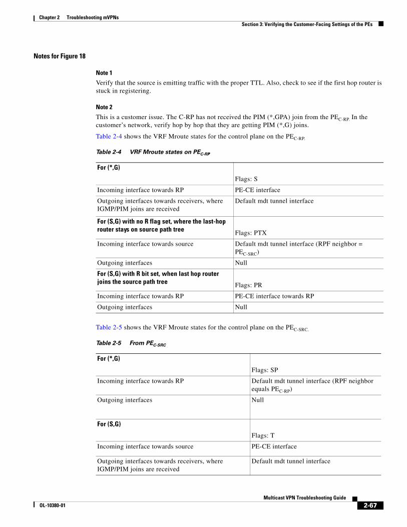
Chapter 2 Troubleshooting mVPNs Section 3: Verifying the Customer-Facing Settings of the PEs
Notes for Figure 18
Note 1
Verify that the source is emitting traffic with the proper TTL. Also, check to see if the first hop router is stuck in registering.
Note 2
This is a customer issue. The C-RP has not received the PIM (*,GPA) join from the PEC-RP. In the customer’s network, verify hop by hop that they are getting PIM (*,G) joins.
Table 2-4 shows the VRF Mroute states for the control plane on the PEC-RP.
Table 2-5 shows the VRF Mroute states for the control plane on the PEC-SRC.
Table 2-4 VRF Mroute states on PEC-RP,
For (*,G)
Flags: S
Incoming interface towards RP PE-CE interface
Outgoing interfaces towards receivers, where IGMP/PIM joins are received
Default mdt tunnel interface
For (S,G) with no R flag set, where the last-hop router stays on source path tree Flags: PTX
Incoming interface towards source Default mdt tunnel interface (RPF neighbor = PEC-SRC)
Outgoing interfaces Null
For (S,G) with R bit set, when last hop router joins the source path tree Flags: PR
Incoming interface towards RP PE-CE interface towards RP
Outgoing interfaces Null
Table 2-5 From PEC-SRC
For (*,G)
Flags: SP
Incoming interface towards RP Default mdt tunnel interface (RPF neighbor equals PEC-RP)
Outgoing interfaces Null
For (S,G)
Flags: T
Incoming interface towards source PE-CE interface
Outgoing interfaces towards receivers, where IGMP/PIM joins are received
Default mdt tunnel interface
2-67Multicast VPN Troubleshooting Guide
OL-10380-01

Chapter 2 Troubleshooting mVPNs Section 3: Verifying the Customer-Facing Settings of the PEs
Table 2-6 shows the VRF Mroute states for the control plane on the PEC-RCVR.
Sample Output for the Mroutes in the VRF Context
The following example shows output when the last hop router joins the shared path tree:
PE3#show ip mroute vrf RED 225.1.1.3 | begin 225 (*, 225.1.1.3), 2d09h/00:02:56, RP 192.168.100.202, flags: S Incoming interface: Serial1/0, RPF nbr 192.168.22.2 Outgoing interface list: Tunnel0, Forward/Sparse-Dense, 2d09h/00:02:56(192.168.1.1, 225.1.1.3), 06:01:53/00:02:26, flags: PR Incoming interface: Serial1/0, RPF nbr 192.168.22.2 Outgoing interface list: Null
PE3#show ip mroute vrf RED 225.1.1.3 | begin 225 (*, 225.1.1.3), 2d09h/00:02:52, RP 192.168.100.202, flags: S Incoming interface: Tunnel0, RPF nbr 172.16.100.2 Outgoing interface list: Serial1/0, Forward/Sparse, 2d09h/00:02:52(192.168.1.1, 225.1.1.3), 06:02:32/00:03:24, flags: T Incoming interface: Tunnel0, RPF nbr 172.16.100.1 Outgoing interface list: Serial1/0, Forward/Sparse, 06:02:32/00:02:52
PE1#show ip mro vrf RED 225.1.1.3 | begin 225(*, 225.1.1.3), 06:03:06/stopped, RP 192.168.100.202, flags: SP Incoming interface: Tunnel7, RPF nbr 172.16.100.2 Outgoing interface list: Null
(192.168.1.1, 225.1.1.3), 06:03:06/00:03:29, flags: T Incoming interface: Serial1/0, RPF nbr 192.168.11.2 Outgoing interface list: Tunnel7, Forward/Sparse-Dense, 06:03:06/00:02:56
Table 2-6 From PEC-RCVR
For (*,G)
Flags: S
Incoming interface towards RP Default mdt tunnel interface (RPF neighbor equals PEC-RP)
Outgoing interfaces towards receivers, where IGMP/PIM joins are received
PE-CE interfaces where the PIM/IGMP joins are received
Note The following entry exists only if the last hop router joins the source path tree.
For (S,G)
Flags: T
Incoming interface towards source Default mdt tunnel interface (RPF neighbor equals PEC-SRC)
Outgoing interfaces towards receivers, where IGMP/PIM joins are received
PE-CE interfaces where the PIM/IGMP joins are received
2-68Multicast VPN Troubleshooting Guide
OL-10380-01

Chapter 2 Troubleshooting mVPNs Section 3: Verifying the Customer-Facing Settings of the PEs
The following example shows the last hop router staying on the shared path tree:
PE2#show ip mroute vrf RED 225.1.1.3 | begin 225(*, 225.1.1.3), 00:05:01/00:03:11, RP 192.168.100.202, flags: S Incoming interface: Serial1/0, RPF nbr 192.168.22.2 Outgoing interface list: Tunnel0, Forward/Sparse-Dense, 00:04:04/00:03:11(192.168.1.1, 225.1.1.3), 00:04:04/00:02:55, flags: PTX Incoming interface: Tunnel0, RPF nbr 172.16.100.1 Outgoing interface list: Null
On PEC-SRC
PE1#show ip mro vrf RED 225.1.1.3 | begin 225(*, 225.1.1.3), 00:04:27/stopped, RP 192.168.100.202, flags: SP Incoming interface: Tunnel7, RPF nbr 172.16.100.2 Outgoing interface list: Null(192.168.1.1, 225.1.1.3), 00:03:42/00:03:29, flags: T Incoming interface: Serial1/0, RPF nbr 192.168.11.2 Outgoing interface list: Tunnel7, Forward/Sparse-Dense, 00:03:42/00:03:24
PE1#show ip mroute vrf RED 225.1.1.3 | begin 225(*, 225.1.1.3), 00:05:25/00:03:24, RP 192.168.100.202, flags: S Incoming interface: Tunnel0, RPF nbr 172.16.100.2 Outgoing interface list: Serial1/0, Forward/Sparse, 00:04:20/00:02:51
Troubleshooting the PIM Adjacency with the CEs
If there is an issue of PIM adjacency on the PE- CE link, the flowchart in Figure 2-19 should be used for troubleshooting or for checking the PIM adjacency.
Repeat the steps of Figure 2-19 as many times as needed, depending on the number of PE-CE links.
2-69Multicast VPN Troubleshooting Guide
OL-10380-01
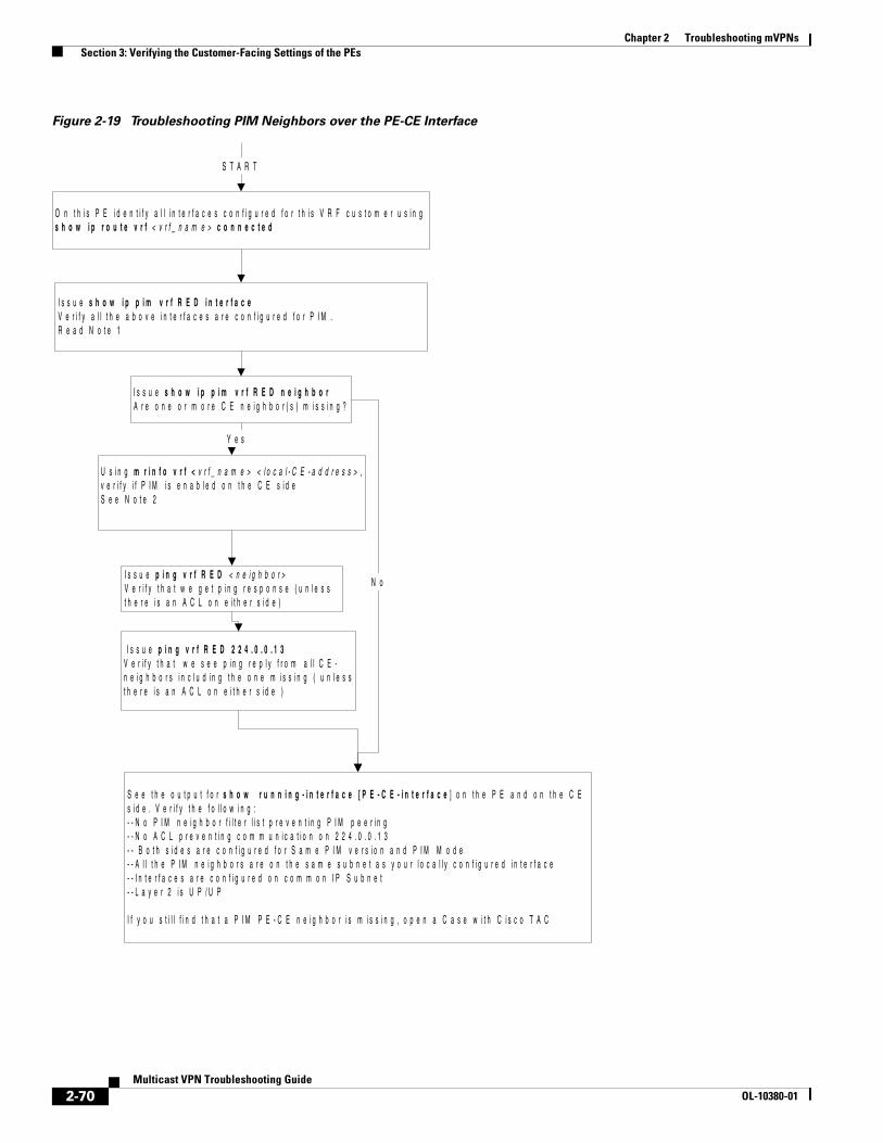
Chapter 2 Troubleshooting mVPNs Section 3: Verifying the Customer-Facing Settings of the PEs
Figure 2-19 Troubleshooting PIM Neighbors over the PE-CE Interface
O n t h i s P E i d e n t i f y a l l i n t e r f a c e s c o n f i g u r e d f o r t h i s V R F c u s t o m e r u s i n gs h o w i p r o u t e v r f < v r f _ n a m e > c o n n e c t e d
I s s u e s h o w i p p i m v r f R E D i n t e r f a c eV e r i f y a l l t h e a b o v e i n t e r f a c e s a r e c o n f i g u r e d f o r P I M .R e a d N o t e 1
I s s u e s h o w i p p i m v r f R E D n e i g h b o rA r e o n e o r m o r e C E n e i g h b o r ( s ) m i s s i n g ?
I s s u e p i n g v r f R E D 2 2 4 . 0 . 0 . 1 3V e r i f y t h a t w e s e e p i n g r e p l y f r o m a l l C E -n e i g h b o r s i n c l u d i n g t h e o n e m i s s i n g ( u n l e s st h e r e i s a n A C L o n e i t h e r s i d e )
I s s u e p i n g v r f R E D < n e i g h b o r >V e r i f y t h a t w e g e t p i n g r e s p o n s e ( u n l e s st h e r e i s a n A C L o n e i t h e r s i d e )
S e e t h e o u t p u t f o r s h o w r u n n i n g - i n t e r f a c e [ P E - C E - i n t e r f a c e ] o n t h e P E a n d o n t h e C Es i d e . V e r i f y t h e f o l l o w i n g :- - N o P I M n e i g h b o r f i l t e r l i s t p r e v e n t i n g P I M p e e r i n g- - N o A C L p r e v e n t i n g c o m m u n i c a t i o n o n 2 2 4 . 0 . 0 . 1 3- - B o t h s i d e s a r e c o n f i g u r e d f o r S a m e P I M v e r s i o n a n d P I M M o d e- - A l l t h e P I M n e i g h b o r s a r e o n t h e s a m e s u b n e t a s y o u r l o c a l l y c o n f i g u r e d i n t e r f a c e- - I n t e r f a c e s a r e c o n f i g u r e d o n c o m m o n I P S u b n e t- - L a y e r 2 i s U P / U P
I f y o u s t i l l f i n d t h a t a P I M P E - C E n e i g h b o r i s m i s s i n g , o p e n a C a s e w i t h C i s c o T A C
S T A R T
Y e s
N o
U s i n g m r i n f o v r f < v r f _ n a m e > < l o c a l - C E - a d d r e s s > ,v e r i f y i f P I M i s e n a b l e d o n t h e C E s i d eS e e N o t e 2
2-70Multicast VPN Troubleshooting Guide
OL-10380-01

Chapter 2 Troubleshooting mVPNs Section 3: Verifying the Customer-Facing Settings of the PEs
Notes for Figure 2-19
Note 1
We might see some additional interfaces, such as MTI and customer interfaces, that are in a shutdown state.
Note 2
It is possible that we do not get any response (if disabled by mrinfo filters or an ACL for igmp).
Sample Output for Troubleshooting the PIM Adjacency on the PE-CE Link
PE1#mrinfo vrf RED 192.168.112.2
192.168.112.2 [version 12.0] [flags: PMA]: 192.168.12.2 -> 0.0.0.0 [1/0/pim/querier/leaf] 192.168.0.2 -> 0.0.0.0 [1/0/pim/disabled/down/leaf] Interface down 192.168.212.2 -> 0.0.0.0 [1/0/pim/disabled/down/leaf] 192.168.112.2 -> 192.168.112.1 [1/0/pim] With PIM enabled
PE1#mrinfo vrf RED 192.168.112.2192.168.112.2 [version 12.0] [flags: PMA]: 192.168.12.2 -> 0.0.0.0 [1/0/pim/querier/leaf] 192.168.0.2 -> 0.0.0.0 [1/0/pim/disabled/down/leaf] 192.168.212.2 -> 0.0.0.0 [1/0/pim/disabled/down/leaf]
We are missing the line for 192.168.112.2 because PIM is not enabled on the CE.
Topology 2In this topology we have added a receiver on the PEC-SRC, on top of what is depicted in Figure 2-9. The pages that follow provide troubleshooting guidelines based on this difference.
2-71Multicast VPN Troubleshooting Guide
OL-10380-01
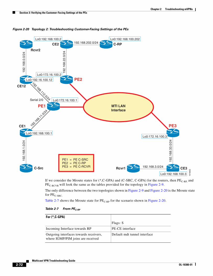
Chapter 2 Troubleshooting mVPNs Section 3: Verifying the Customer-Facing Settings of the PEs
Figure 2-20 Topology 2: Troubleshooting Customer-Facing Settings of the PEs
If we consider the Mroute states for (*,C-GPA) and (C-SRC, C-GPA) for the routers, then PEC-RP, and PEC-RCVR will look the same as the tables provided for the topology in Figure 2-9.
The only difference between the two topologies shown in Figure 2-9 and Figure 2-20 is the Mroute state for PEC-SRC.
Table 2-7 shows the Mroute state for PEC-RP for the scenario shown in Figure 2-20.
PE1
CE2 C-RP192.168.202.0/24
Rcvr1 192.168.3.0/24
PE2
192.
168.
22.0
/24
CE1
192.
168.
1.0/
24
C-Src
192.
168.
11.0
/24
PE3
CE319
2.16
8.33
.0/2
4
Lo0:192.168.100.2 Lo0:192.168.100.202
Lo0:172.16.100.2
Lo0:172.16.100.1
Lo0:192.168.100.1
PE1 = PE C-SRCPE2 = PE C-RPPE3 = PE C-RCVR
Lo0:192.168.100.3
Lo0:172.16.100.3
1418
43
MTI LANInterface
CE12
Serial 2/0
192.
168.
0.0/
24
192.168.112.0/24
Lo0:192.16.100.12
Rcvr2
Table 2-7 From PEC-RP
For (*,C-GPA)
Flags: S
Incoming Interface towards RP PE-CE interface
Outgoing interfaces towards receivers, where IGMP/PIM joins are received
Default mdt tunnel interface
2-72Multicast VPN Troubleshooting Guide
OL-10380-01

Chapter 2 Troubleshooting mVPNs Section 3: Verifying the Customer-Facing Settings of the PEs
Table 2-8 shows the Mroute state for PEC-SRC for the scenario shown in Figure 2-20.
The following tables show the Mroute state for PEC-RCVR for the scenario shown in Figure 2-20.
For (C-SRC, C-GPA)
Flags: PR
Incoming Interface towards RP PE-CE interface towards RP
Outgoing Interfaces Null
Table 2-7 From PEC-RP
Table 2-8 Mroute for PEC-SRC
For (*,G)
Flags: S
Incoming interface towards RP Default mdt tunnel interface (RPF neighbor equals PEC-RP)
Outgoing interfaces towards Receivers PE-CE interface
PE-CE Interface towards Rcvr 2
For (S,G)
Flags: T
Incoming interface towards source PE-CE interface
Outgoing interfaces towards receivers PE-CE interface
Default mdt tunnel interface plus PE-CE interfaces towards Rcvr 2
Table 2-9 Mroute for PEC-RCVR
For (*,G)
Flags: S
Incoming interface towards RP Default mdt tunnel interface (RPF neighbor = PEC-RP)
Outgoing interfaces towards receivers, where IGMP/PIM joins are received
PE-CE interfaces where the PIM/IGMP joins are received
Note The following entry exists only if the last hop router joins the source path tree.
For (S,G)
Flags: T
Incoming Interface towards source Default mdt tunnel interface (RPF neighbor =PEC-SRC)
Outgoing interfaces towards receivers, where IGMP/PIM Joins are received
PE-CE interfaces where the PIM/IGMP joins are received
2-73Multicast VPN Troubleshooting Guide
OL-10380-01
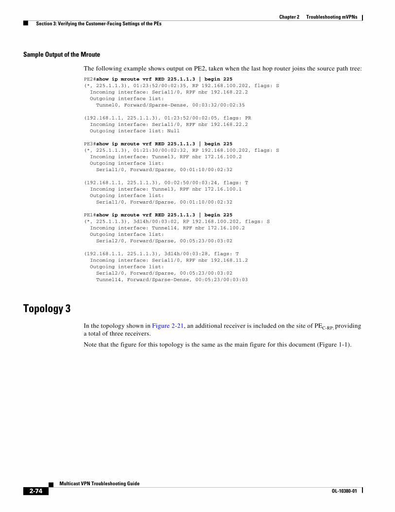
Chapter 2 Troubleshooting mVPNs Section 3: Verifying the Customer-Facing Settings of the PEs
Sample Output of the Mroute
The following example shows output on PE2, taken when the last hop router joins the source path tree:
PE2#show ip mroute vrf RED 225.1.1.3 | begin 225(*, 225.1.1.3), 01:23:52/00:02:35, RP 192.168.100.202, flags: S Incoming interface: Serial1/0, RPF nbr 192.168.22.2 Outgoing interface list: Tunnel0, Forward/Sparse-Dense, 00:03:32/00:02:35
(192.168.1.1, 225.1.1.3), 01:23:52/00:02:05, flags: PR Incoming interface: Serial1/0, RPF nbr 192.168.22.2 Outgoing interface list: Null
PE3#show ip mroute vrf RED 225.1.1.3 | begin 225(*, 225.1.1.3), 01:21:30/00:02:32, RP 192.168.100.202, flags: S Incoming interface: Tunnel3, RPF nbr 172.16.100.2 Outgoing interface list: Serial1/0, Forward/Sparse, 00:01:10/00:02:32
(192.168.1.1, 225.1.1.3), 00:02:50/00:03:24, flags: T Incoming interface: Tunnel3, RPF nbr 172.16.100.1 Outgoing interface list: Serial1/0, Forward/Sparse, 00:01:10/00:02:32
PE1#show ip mroute vrf RED 225.1.1.3 | begin 225(*, 225.1.1.3), 3d14h/00:03:02, RP 192.168.100.202, flags: S Incoming interface: Tunnel14, RPF nbr 172.16.100.2 Outgoing interface list: Serial2/0, Forward/Sparse, 00:05:23/00:03:02
(192.168.1.1, 225.1.1.3), 3d14h/00:03:28, flags: T Incoming interface: Serial1/0, RPF nbr 192.168.11.2 Outgoing interface list: Serial2/0, Forward/Sparse, 00:05:23/00:03:02 Tunnel14, Forward/Sparse-Dense, 00:05:23/00:03:03
Topology 3In the topology shown in Figure 2-21, an additional receiver is included on the site of PEC-RP; providing a total of three receivers.
Note that the figure for this topology is the same as the main figure for this document (Figure 1-1).
2-74Multicast VPN Troubleshooting Guide
OL-10380-01
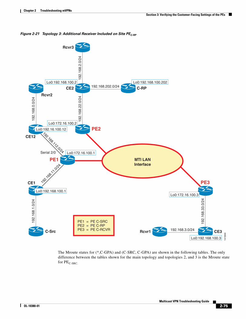
Chapter 2 Troubleshooting mVPNs Section 3: Verifying the Customer-Facing Settings of the PEs
Figure 2-21 Topology 3: Additional Receiver Included on Site PEC-RP
The Mroute states for (*,C-GPA) and (C-SRC, C-GPA) are shown in the following tables. The only difference between the tables shown for the main topology and topologies 2, and 3 is the Mroute state for PEC-SRC.
PE1
CE2 C-RP192.168.202.0/24
Rcvr1 192.168.3.0/24
PE2
192.
168.
22.0
/24
CE1
192.
168.
1.0/
24
C-Src
192.
168.
11.0
/24
PE3
CE3
192.
168.
33.0
/24
Lo0:192.168.100.2 Lo0:192.168.100.202
Lo0:172.16.100.2
Lo0:172.16.100.1
Lo0:192.168.100.1
PE1 = PE C-SRCPE2 = PE C-RPPE3 = PE C-RCVR
Lo0:192.168.100.3
Lo0:172.16.100.3
1418
44
MTI LANInterface
CE12
Serial 2/0
192.
168.
0.0/
24
192.168.112.0/24
Lo0:192.16.100.12
Rcvr2
192.
168.
2.0/
24
Rcvr3
2-75Multicast VPN Troubleshooting Guide
OL-10380-01
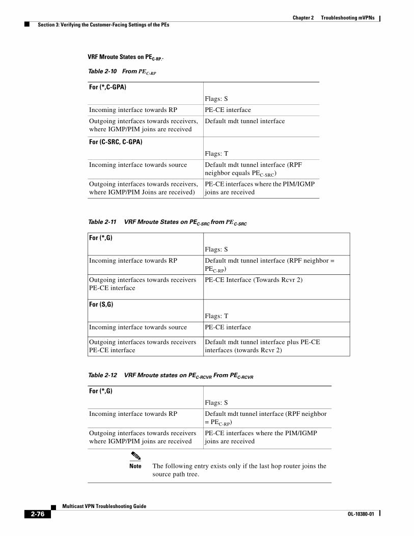
Chapter 2 Troubleshooting mVPNs Section 3: Verifying the Customer-Facing Settings of the PEs
VRF Mroute States on PEC-RP..
Table 2-10 From PEC-RP
For (*,C-GPA)
Flags: S
Incoming interface towards RP PE-CE interface
Outgoing interfaces towards receivers, where IGMP/PIM joins are received
Default mdt tunnel interface
For (C-SRC, C-GPA)
Flags: T
Incoming interface towards source Default mdt tunnel interface (RPF neighbor equals PEC-SRC)
Outgoing interfaces towards receivers, where IGMP/PIM Joins are received)
PE-CE interfaces where the PIM/IGMP joins are received
Table 2-11 VRF Mroute States on PEC-SRC from PEC-SRC
For (*,G)
Flags: S
Incoming interface towards RP Default mdt tunnel interface (RPF neighbor = PEC-RP)
Outgoing interfaces towards receivers PE-CE interface
PE-CE Interface (Towards Rcvr 2)
For (S,G)
Flags: T
Incoming interface towards source PE-CE interface
Outgoing interfaces towards receivers PE-CE interface
Default mdt tunnel interface plus PE-CE interfaces (towards Rcvr 2)
Table 2-12 VRF Mroute states on PEC-RCVR From PEC-RCVR
For (*,G)
Flags: S
Incoming interface towards RP Default mdt tunnel interface (RPF neighbor = PEC-RP)
Outgoing interfaces towards receivers where IGMP/PIM joins are received
PE-CE interfaces where the PIM/IGMP joins are received
Note The following entry exists only if the last hop router joins the source path tree.
2-76Multicast VPN Troubleshooting Guide
OL-10380-01

Chapter 2 Troubleshooting mVPNs Section 3: Verifying the Customer-Facing Settings of the PEs
Sample Output of Multicast Routes for Topology 3
The following example shows output when the last hop router joins the source path tree:
PE2#show ip mroute vrf RED 225.1.1.3 | begin 225(*, 225.1.1.3), 01:40:58/00:02:53, RP 192.168.100.202, flags: S Incoming interface: Serial1/0, RPF nbr 192.168.22.2 Outgoing interface list: Tunnel0, Forward/Sparse-Dense, 00:00:45/00:02:53
(192.168.1.1, 225.1.1.3), 01:40:58/00:03:29, flags: T Incoming interface: Tunnel0, RPF nbr 172.16.100.1 Outgoing interface list: Serial1/0, Forward/Sparse, 00:00:45/00:02:53
PE3#show ip mroute vrf RED 225.1.1.3 | begin 225(*, 225.1.1.3), 01:41:12/00:02:42, RP 192.168.100.202, flags: S Incoming interface: Tunnel3, RPF nbr 172.16.100.2 Outgoing interface list: Serial1/0, Forward/Sparse, 00:00:59/00:02:42
(192.168.1.1, 225.1.1.3), 00:22:31/00:03:23, flags: T Incoming interface: Tunnel3, RPF nbr 172.16.100.1 Outgoing interface list: Serial1/0, Forward/Sparse, 00:00:59/00:02:42
PE1#show ip mroute vrf RED 225.1.1.3 | begin 225(*, 225.1.1.3), 3d14h/00:03:08, RP 192.168.100.202, flags: S Incoming interface: Tunnel14, RPF nbr 172.16.100.2 Outgoing interface list: Serial2/0, Forward/Sparse, 00:00:26/00:03:08
(192.168.1.1, 225.1.1.3), 3d14h/00:03:24, flags: T Incoming interface: Serial1/0, RPF nbr 192.168.11.2 Outgoing interface list: Serial2/0, Forward/Sparse, 00:00:26/00:03:08 Tunnel14, Forward/Sparse-Dense, 00:00:26/00:03:10
For (S,G)
Flags: T
Incoming interface towards source Default mdt tunnel interface (RPF neighbor =PEC-SRC)
Outgoing interfaces towards receivers, where IGMP/PIM joins are received
PE-CE interfaces where the PIM/IGMP joins are received
Table 2-12 VRF Mroute states on PEC-RCVR From PEC-RCVR
2-77Multicast VPN Troubleshooting Guide
OL-10380-01

Chapter 2 Troubleshooting mVPNs Section 3: Verifying the Customer-Facing Settings of the PEs
Topology 4The topology in Figure 2-22 shows that the PEC-SRC and the PEC-RP are on the same site.
Figure 2-22 PEC-SRC and the PEC-RP On the Same Site
CE2 C-RP192.168.202.0/24
Rcvr1 192.168.3.0/24
PE2
192.
168.
22.0
/24
PE3
CE3
192.
168.
33.0
/24
Lo0:192.168.100.2 Lo0:192.168.100.202
Lo0:172.16.100.2
PE2 = PE C-RPPE3 = PE C-RCVR
Lo0:192.168.100.3
Lo0:172.16.100.3
1418
45
MTI LANInterface
192.
168.
2.0/
24
Rcvr3
2-78Multicast VPN Troubleshooting Guide
OL-10380-01
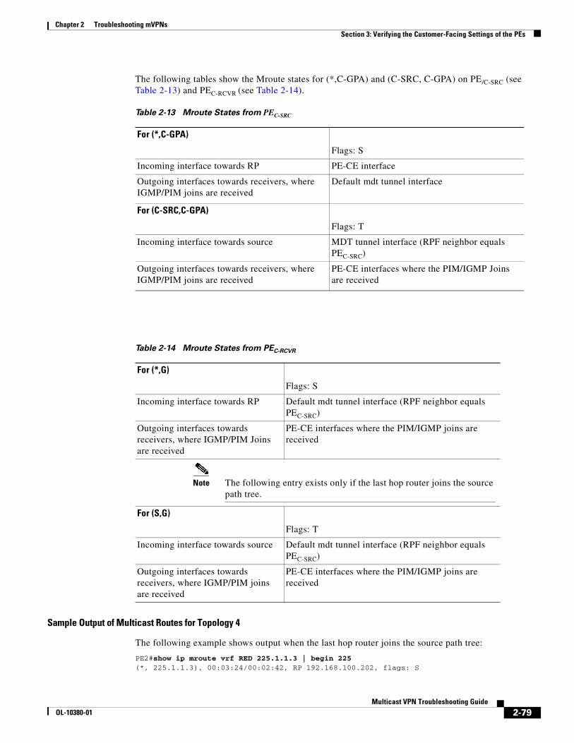
Chapter 2 Troubleshooting mVPNs Section 3: Verifying the Customer-Facing Settings of the PEs
The following tables show the Mroute states for (*,C-GPA) and (C-SRC, C-GPA) on PE/C-SRC (see Table 2-13) and PEC-RCVR (see Table 2-14).
Sample Output of Multicast Routes for Topology 4
The following example shows output when the last hop router joins the source path tree:
PE2#show ip mroute vrf RED 225.1.1.3 | begin 225(*, 225.1.1.3), 00:03:24/00:02:42, RP 192.168.100.202, flags: S
Table 2-13 Mroute States from PEC-SRC
For (*,C-GPA)
Flags: S
Incoming interface towards RP PE-CE interface
Outgoing interfaces towards receivers, where IGMP/PIM joins are received
Default mdt tunnel interface
For (C-SRC,C-GPA)
Flags: T
Incoming interface towards source MDT tunnel interface (RPF neighbor equals PEC-SRC)
Outgoing interfaces towards receivers, where IGMP/PIM joins are received
PE-CE interfaces where the PIM/IGMP Joins are received
Table 2-14 Mroute States from PEC-RCVR
For (*,G)
Flags: S
Incoming interface towards RP Default mdt tunnel interface (RPF neighbor equals PEC-SRC)
Outgoing interfaces towards receivers, where IGMP/PIM Joins are received
PE-CE interfaces where the PIM/IGMP joins are received
Note The following entry exists only if the last hop router joins the source path tree.
For (S,G)
Flags: T
Incoming interface towards source Default mdt tunnel interface (RPF neighbor equals PEC-SRC)
Outgoing interfaces towards receivers, where IGMP/PIM joins are received
PE-CE interfaces where the PIM/IGMP joins are received
2-79Multicast VPN Troubleshooting Guide
OL-10380-01
Chapter 2 Troubleshooting mVPNs Section 4: Verifying mVPN Data Flow
Incoming interface: Serial1/0, RPF nbr 192.168.22.2 Outgoing interface list: Tunnel0, Forward/Sparse-Dense, 00:03:01/00:02:42
(192.168.2.1, 225.1.1.3), 00:03:01/00:03:26, flags: T Incoming interface: Serial1/0, RPF nbr 192.168.22.2 Outgoing interface list: Tunnel0, Forward/Sparse-Dense, 00:03:01/00:02:42
PE3#show ip mroute vrf RED 225.1.1.3 | begin 225(*, 225.1.1.3), 02:07:48/00:02:34, RP 192.168.100.202, flags: S Incoming interface: Tunnel3, RPF nbr 172.16.100.2 Outgoing interface list: Serial1/0, Forward/Sparse, 00:27:34/00:02:34
(192.168.2.1, 225.1.1.3), 00:12:40/00:03:21, flags: T Incoming interface: Tunnel3, RPF nbr 172.16.100.2 Outgoing interface list: Serial1/0, Forward/Sparse, 00:12:40/00:02:34
Section 4: Verifying mVPN Data FlowThis section provides the steps that can be used to troubleshoot the mVPN data flow. The topology shown in Figure 2-23 is used to cover the different show commands that can be used to monitor the data flow. Note that this section covers only the data flow on the default MDT and not on the data MDT.
Assumptions
The following assumptions are made:
• Mroute state entries for (*,C-GPA) and (C-SRC, C-GPA) are present with valid incoming interface list (IIL) and outgoing interface list (OIL) in the mVRF table on PEC-SRC and PEC-RCVR.
• The last hop routers (CE3 and CE12 for the topology in Figure 2-23),where the receivers are connected, are configured to join the shortest path tree (for example, SPT equals 0 on last hop routers).
• There is no backdoor connectivity between the VPN sites.
• The topology in Figure 2-23 shows one PEC-RCVR. If there is more than one, the same concept can be used to analyze and troubleshoot the additional data flow.
• There are no multicast-boundary, ACLs, multicast-threshold settings in the SP core and edge that are dropping the packet.
• This section focuses on one flow (C-SRC, C-GPA); the same steps can be used for checking additional flows.
2-80Multicast VPN Troubleshooting Guide
OL-10380-01
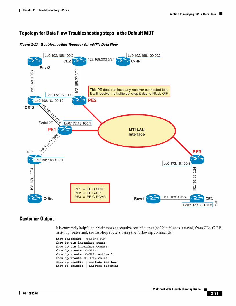
Chapter 2 Troubleshooting mVPNs Section 4: Verifying mVPN Data Flow
Topology for Data Flow Troubleshooting steps in the Default MDT
Figure 2-23 Troubleshooting Topology for mVPN Data Flow
Customer Output
It is extremely helpful to obtain two consecutive sets of output (at 30 to 60 secs interval) from CEs, C-RP, first-hop router and, the last-hop routers using the following commands:
show interface <Facing_PE>show ip pim interface stats show ip pim interface countsshow ip mroute <C-GPA> show ip mroute <C-GPA> active 1 show ip mroute <C-GPA> count show ip traffic | include bad hopshow ip traffic | include fragment
PE1
CE2 C-RP192.168.202.0/24
Rcvr1 192.168.3.0/24
PE2
192.
168.
22.0
/24
CE1
192.
168.
1.0/
24
C-Src
192.
168.
11.0
/24
PE3
CE319
2.16
8.33
.0/2
4
Lo0:192.168.100.2 Lo0:192.168.100.202
Lo0:172.16.100.2
Lo0:172.16.100.1
Lo0:192.168.100.1
PE1 = PE C-SRCPE2 = PE C-RPPE3 = PE C-RCVR
This PE does not have any receiver connected to it.It will receive the traffic but drop it due to NULL OIF
Lo0:192.168.100.3
Lo0:172.16.100.3
1418
46
MTI LANInterface
CE12
Serial 2/0
192.
168.
0.0/
24
192.168.112.0/24
Lo0:192.16.100.12
Rcvr2
2-81Multicast VPN Troubleshooting Guide
OL-10380-01

Chapter 2 Troubleshooting mVPNs Section 4: Verifying mVPN Data Flow
Verifying Mroute States on PEC-SRC and PEC-RCVR
The control plane states on PEC-SRC and PEC-RCVR will provide output that is similar to that shown in the following examples.
PEC-SRC receives the traffic from one customer site and replicates it to other local sites where there are interested receivers. If there are interested sites on other PEs, then PEC-SRC replicates the stream over the MTI interface for this mVRF. The following example shows output from the PEs:
PE1#show ip mroute vrf RED 225.1.1.10 | begin 225(*, 225.1.1.10), 07:16:49/00:03:07, RP 192.168.100.202, flags: S Incoming interface: Tunnel7, RPF nbr 172.16.100.2 Outgoing interface list: Serial2/0, Forward/Sparse, 07:04:28/00:03:07
(192.168.1.1, 225.1.1.10), 02:28:47/00:03:24, flags: T Incoming interface: Serial1/0, RPF nbr 192.168.11.2 Outgoing interface list: Serial2/0, Forward/Sparse, 02:28:47/00:03:07 Tunnel7, Forward/Sparse-Dense, 02:28:47/00:03:27
PE3# show ip mroute vrf RED 225.1.1.10 | begin 225(*, 225.1.1.10), 02:39:18/00:03:06, RP 192.168.100.202, flags: S Incoming interface: Tunnel0, RPF nbr 172.16.100.2 Outgoing interface list: Serial1/0, Forward/Sparse, 02:39:18/00:03:06
(192.168.1.1, 225.1.1.10), 02:28:24/00:03:22, flags: T Incoming interface: Tunnel0, RPF nbr 172.16.100.1 Outgoing interface list: Serial1/0, Forward/Sparse, 02:28:24/00:03:06
The flowchart in Figure 2-24 shows how to monitor the mVPN data flow.
2-82Multicast VPN Troubleshooting Guide
OL-10380-01

Chapter 2 Troubleshooting mVPNs Section 4: Verifying mVPN Data Flow
Figure 2-24 Troubleshooting mVPN Data Flow
O n P E C - S R C , v e r i f y m u l t i c a s t s t r e a m f r o m C - S r c i s r e p l i c a t e d t o o t h e r l o c a l m V P N s i t e s h a v i n g r e c e i v e r s o n t h e s a m e P E . C h e c k i n t e r f a c e S t a t i s t i c s : s e e N o t e 3s h o w i p p i m v r f < v r f _ n a m e > i n t e r f a c e s t a t s : “ O c t e t s o u t ” a n d “ M p a c k e t s o u t ” s h o w i p p i m v r f < v r f _ n a m e > i n t e r f a c e c o u n t : “ M p a c k e t s o u t ” s h o w i n t e r f a c e < P E - C E i n t e r f a c e > : o u t p u t t r a f f i c a n d o u t p u t d r o p s
D 1 . 0
D 1 . 1
D 1 . 2
O n P E C - R C V R , v e r i f y t r a f f i c r e c e i v e d o v e r m d t - G P A i s c o r r e c t l y d e c a p s u l a t e d a n d s e n t t o t h e m V R F . U s e t h e f o l l o w i n g :s h o w i p p i m v r f < v r f _ n a m e > i n t e r f a c e s t a t s h o w i p m r o u t e v r f < v r f _ n a m e > m r o u t e C - G P A c o u n ts h o w i p m r o u t e v r f < v r f _ n a m e > m r o u t e C - G P A a c t i v e
D 1 . 3
D 1 . 4
R e a d N o t e 1O n P E C - S R C , v e r i f y t h a t a m u l t i c a s t s t r e a m i s r e c e i v e d f r o m C - S r c :
I n t e r f a c e S t a t i s t i c s : I n c l u d e s a l l u n i c a s t a n d m u l t i c a s t t r a f f i c s e n t a n d r e c e i v e d f r o m t h e C E ( o n t h e s i t e h a v i n g C - S r c )s h o w i p p i m v r f < v r f _ n a m e > i n t e r f a c e s t a t s = > “ O c t e t s i n ” a n d “ M p a c k e t s i n ” s h o w i p p i m v r f < v r f _ n a m e > i n t e r f a c e c o u n t = > “ M p a c k e t s i n ” s h o w i n t e r f a c e < P E - C E i n t e r f a c e t o w a r d s C - S r c > = > i n p u t p a c k e t / b y t e s c o u n t . W a t c h f o r i n p u t q u e u e d r o p s & I n p u t Q u e u e w e d g e d
M r o u t e s t a t i s t i c s : I n c l u d e s m u l t i c a s t s t a t i c s f o r t h e r o u t e r m u l t i c a s t t r a f f i cS e e N o t e 2 ; U s e t h e f o l l o w i n g :s h o w i p m r o u t e v r f < v r f _ n a m e > < C - G P A > a c t i v e 1 s h o w i p m r o u t e v r f < v r f _ n a m e > < C - G P A > c o u n t
E x t r a c h e c k s :s h o w i p t r a f f i c | i n c b a d h o p : i d e n t i f y T T L i s s u e s s h o w i p t r a f f i c | i n c f r a g : h e l p i s o l a t e p a c k e t d r o p s
I s t h e m u l t i c a s t s t r e a m f r o m C - S R C s w i t c h e d f r o m P E C - R C V R t o l o c a l r e c e i v e r s ?R e a d N o t e 5 . U s e t h e f o l l o w i n g :s h o w i p p i m v r f < v r f _ n a m e > i n t e r f a c e s t a ts h o w i n t < P E - C E i n t e r f a c e >
O n P E C - R C V R , v e r i f y m u l t i c a s t s t r e a m f r o m P E C - S r c i s r e c e i v e d o v e r m d t - G P A :V e r i f y t h a t t r a f f i c i s r e c e i v e d a n d c o u n t s m a t c h w i t h w h a t i s b e i n g s e n t f r o m P E C - S r c . ( I n D 1 . 2 ) . U s e t h e f o l l o w i n g :s h o w i p m r o u t e < m d t - g p a > a c t i v e 1 , c h e c k f o r ( P E - S R C , m d t - G P A ) s h o w i p m r o u t e < m d t - G P A > c o u n t , c h e c k f o r ( P E - S R C , m d t - G P A ) s h o w i n t t u n n e l X ( w a t c h f o r i n c o m i n g p a c k e t s / b p s )
R e a d N o t e 4
2-83Multicast VPN Troubleshooting Guide
OL-10380-01

Chapter 2 Troubleshooting mVPNs Section 4: Verifying mVPN Data Flow
Notes for Figure 2-24
Note 1
• We assume that multicast stream in question is the traffic flowing from C-SRC to C-GPA.
• Note that most of the output needs to be captured twice, at 30 to 60 second intervals, so we can compare the evolution of the traffic flow.
Note 2
• Interface Statistics: Includes all unicast and multicast traffic sent and received from the CE (on the site having C-SRC):
show ip pim vrf vrf_name interface stats
Look for Octets in and Mpackets in count and verify it is increasing.
show ip pim vrf vrf_name interface count
Look for Mpackets in count and verify it is increasing.
show interface PE-CE interface towards C-SRC
Check for the input packet/bytes count and verify it is increasing, watch for input queue drops and Input Queue Wedged.
• Mroute statistics: Includes multicast statics for:
show ip mroute vrf vrf_name C-GPA active 1
Check for multicast stream from C-SRC, and note the kbps.
show ip mroute vrf vrf_name C-GPA count
Check for multicast stream from C-SRC, note the Forwarding Counts, and watch for RPF or other drops.
• Extra checks:
show ip traffic | inc bad hop to identify TTL issues (it is a per-box counter).
show ip traffic | inc frag to help isolate packet drops due to DF bit set on the C-SRC and low MTU on MTI. (It is a per-box counter). This is less likely to be an issue in production.
• Includes all unicast and multicast traffic sent and received from the CE (on the site having C-RCVR).
show ip pim vrf vrf_name interface stats
Look for the Octets out and Mpackets out count and verify it is increasing.
show ip pim vrf vrf_name interface count
Look for the Mpackets out count and verify it is increasing.
show interface PE-CE interface
Check for output traffic and output drops.
• If the PE-CE link is a frame relay interface, then watch for counter broadcasts sent or dropped x/y under the show interface PE-CE_interface command.
Note 3
• On PEC-RCVR, verify that the multicast stream from PEC-SRC is received over mdt-GPA.
• Use the following output to verify that the traffic is received and the counts match with what is being sent from PEC-SRC:
2-84Multicast VPN Troubleshooting Guide
OL-10380-01
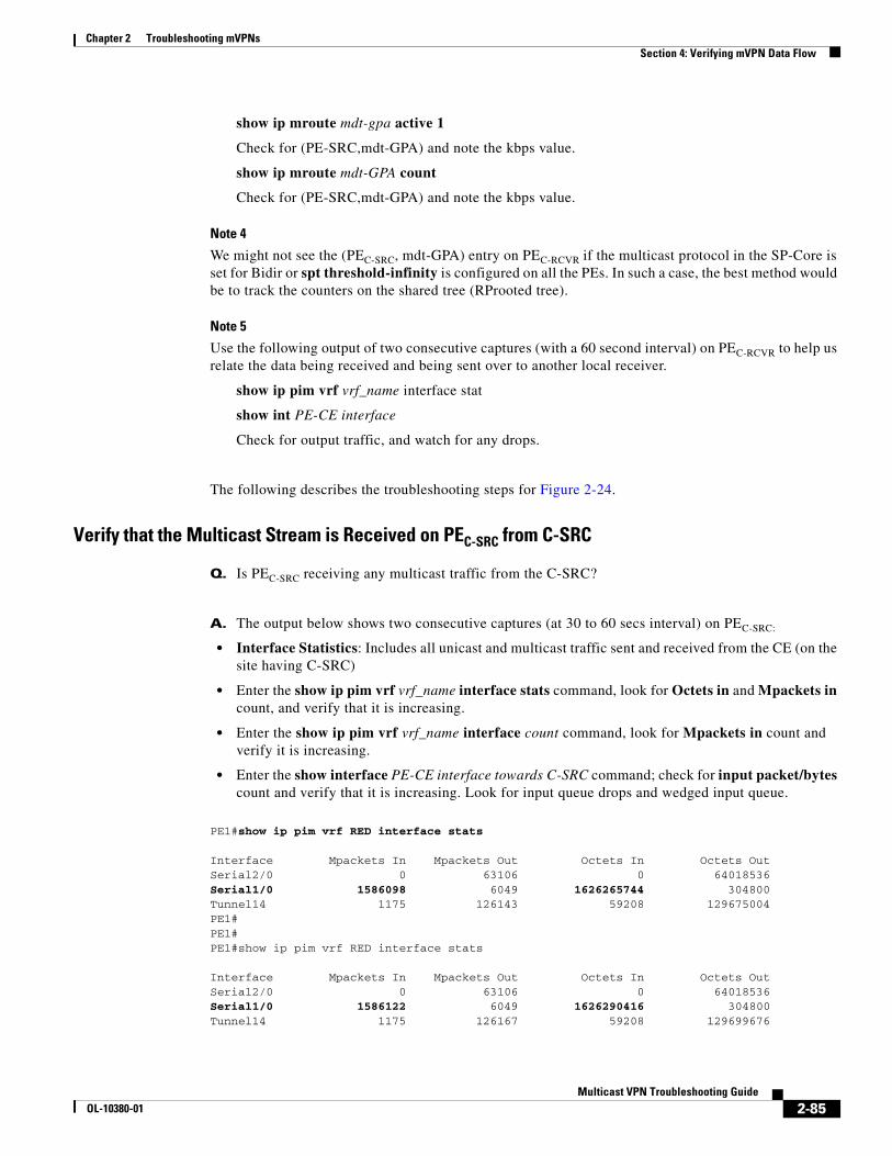
Chapter 2 Troubleshooting mVPNs Section 4: Verifying mVPN Data Flow
show ip mroute mdt-gpa active 1
Check for (PE-SRC,mdt-GPA) and note the kbps value.
show ip mroute mdt-GPA count
Check for (PE-SRC,mdt-GPA) and note the kbps value.
Note 4
We might not see the (PEC-SRC, mdt-GPA) entry on PEC-RCVR if the multicast protocol in the SP-Core is set for Bidir or spt threshold-infinity is configured on all the PEs. In such a case, the best method would be to track the counters on the shared tree (RProoted tree).
Note 5
Use the following output of two consecutive captures (with a 60 second interval) on PEC-RCVR to help us relate the data being received and being sent over to another local receiver.
show ip pim vrf vrf_name interface stat
show int PE-CE interface
Check for output traffic, and watch for any drops.
The following describes the troubleshooting steps for Figure 2-24.
Verify that the Multicast Stream is Received on PEC-SRC from C-SRC
Q. Is PEC-SRC receiving any multicast traffic from the C-SRC?
A. The output below shows two consecutive captures (at 30 to 60 secs interval) on PEC-SRC:
• Interface Statistics: Includes all unicast and multicast traffic sent and received from the CE (on the site having C-SRC)
• Enter the show ip pim vrf vrf_name interface stats command, look for Octets in and Mpackets in count, and verify that it is increasing.
• Enter the show ip pim vrf vrf_name interface count command, look for Mpackets in count and verify it is increasing.
• Enter the show interface PE-CE interface towards C-SRC command; check for input packet/bytes count and verify that it is increasing. Look for input queue drops and wedged input queue.
PE1#show ip pim vrf RED interface stats
Interface Mpackets In Mpackets Out Octets In Octets OutSerial2/0 0 63106 0 64018536Serial1/0 1586098 6049 1626265744 304800Tunnel14 1175 126143 59208 129675004PE1#PE1#PE1#show ip pim vrf RED interface stats
Interface Mpackets In Mpackets Out Octets In Octets OutSerial2/0 0 63106 0 64018536Serial1/0 1586122 6049 1626290416 304800Tunnel14 1175 126167 59208 129699676
2-85Multicast VPN Troubleshooting Guide
OL-10380-01

Chapter 2 Troubleshooting mVPNs Section 4: Verifying mVPN Data Flow
PE1#show ip pim vrf RED interface count
State: * - Fast Switched, D - Distributed Fast Switched H - Hardware Switching EnabledAddress Interface FS Mpackets In/Out192.168.112.1 Serial2/0 * 0/63106192.168.11.1 Serial1/0 * 1586135/6049172.16.100.1 Tunnel14 * 1175/126180
PE1#show ip pim vrf RED interface count
State: * - Fast Switched, D - Distributed Fast Switched H - Hardware Switching EnabledAddress Interface FS Mpackets In/Out192.168.112.1 Serial2/0 * 0/63106192.168.11.1 Serial1/0 * 1586149/6049172.16.100.1 Tunnel14 * 1175/126194
Note These counters represent aggregated multicast traffic coming from the customer. The multicast traffic can belong to any GPA and can originate from any C-SRC address.
Q. Is PEC-SRC receiving (C-SRC, C-GPA) multicast traffic from the C-SRC?
A. The following sample output shows how to verify if the PEC-SRC is receiving traffic.
• Mroute statistics: Includes multicast statics for the (C-SRC, C-GPA)
• Enter the show ip mroute vrf vrf_name C-GPA active 1 command to check for multicast stream from C-SRC (note the kpbps)
• Enter the show ip mroute vrf vrf_name C-GPA count command to check for multicast stream from C-SRC. Note the forwarding counts and look for RPF or other drops.
The output can help in verifying that the Forwarding Counts are increasing for the (C-SRC, C-GPA) entry.
PE1#show ip mroute vrf RED 225.1.1.10 active 1Active IP Multicast Sources - sending >= 1 kbps
Group: 225.1.1.10, (?) Source: 192.168.1.1 (?) Rate: 1 pps/8 kbps(1sec), 8 kbps(last 30 secs), 7 kbps(life avg)PE1#show ip mroute vrf RED 225.1.1.10 count IP Multicast Statistics18 routes using 10408 bytes of memory12 groups, 0.50 average sources per groupForwarding Counts: Pkt Count/Pkts per second/Avg Pkt Size/Kilobits per secondOther counts: Total/RPF failed/Other drops(OIF-null, rate-limit etc)
Group: 225.1.1.10, Source count: 1, Group pkt count: 1893 RP-tree: Forwarding: 2/0/1028/0, Other: 3/1/0 Source: 192.168.1.1/32, Forwarding: 1891/1/1028/8, Other: 1892/0/1
PE1#show ip mroute vrf RED 225.1.1.10 active 1Active IP Multicast Sources - sending >= 1 kbps
Group: 225.1.1.10, (?) Source: 192.168.1.1 (?) Rate: 1 pps/9 kbps(1sec), 9 kbps(last 10 secs), 8 kbps(life avg)
PE1#show ip mroute vrf RED 225.1.1.10 count IP Multicast Statistics
2-86Multicast VPN Troubleshooting Guide
OL-10380-01
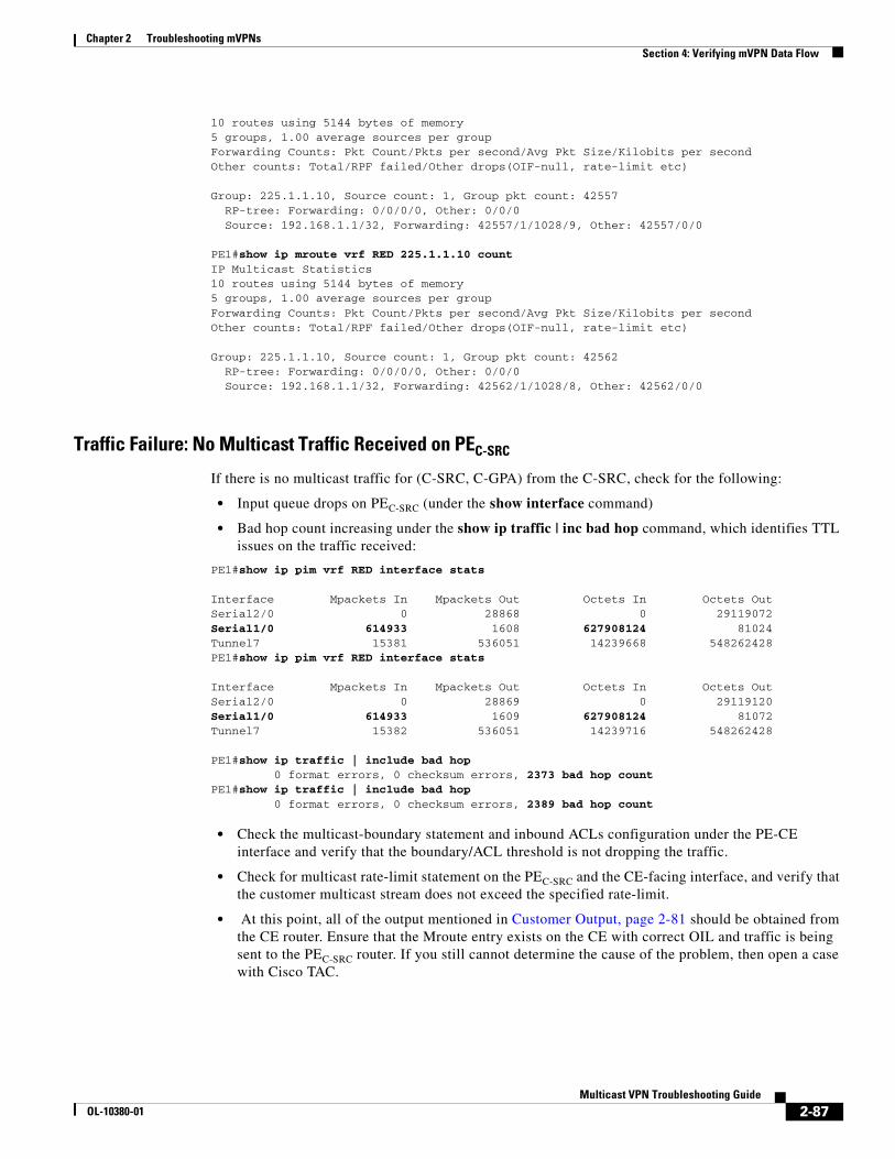
Chapter 2 Troubleshooting mVPNs Section 4: Verifying mVPN Data Flow
10 routes using 5144 bytes of memory5 groups, 1.00 average sources per groupForwarding Counts: Pkt Count/Pkts per second/Avg Pkt Size/Kilobits per secondOther counts: Total/RPF failed/Other drops(OIF-null, rate-limit etc)
Group: 225.1.1.10, Source count: 1, Group pkt count: 42557 RP-tree: Forwarding: 0/0/0/0, Other: 0/0/0 Source: 192.168.1.1/32, Forwarding: 42557/1/1028/9, Other: 42557/0/0
PE1#show ip mroute vrf RED 225.1.1.10 count IP Multicast Statistics10 routes using 5144 bytes of memory5 groups, 1.00 average sources per groupForwarding Counts: Pkt Count/Pkts per second/Avg Pkt Size/Kilobits per secondOther counts: Total/RPF failed/Other drops(OIF-null, rate-limit etc)
Group: 225.1.1.10, Source count: 1, Group pkt count: 42562 RP-tree: Forwarding: 0/0/0/0, Other: 0/0/0 Source: 192.168.1.1/32, Forwarding: 42562/1/1028/8, Other: 42562/0/0
Traffic Failure: No Multicast Traffic Received on PEC-SRC
If there is no multicast traffic for (C-SRC, C-GPA) from the C-SRC, check for the following:
• Input queue drops on PEC-SRC (under the show interface command)
• Bad hop count increasing under the show ip traffic | inc bad hop command, which identifies TTL issues on the traffic received:
PE1#show ip pim vrf RED interface stats
Interface Mpackets In Mpackets Out Octets In Octets OutSerial2/0 0 28868 0 29119072Serial1/0 614933 1608 627908124 81024Tunnel7 15381 536051 14239668 548262428PE1#show ip pim vrf RED interface stats
Interface Mpackets In Mpackets Out Octets In Octets OutSerial2/0 0 28869 0 29119120Serial1/0 614933 1609 627908124 81072Tunnel7 15382 536051 14239716 548262428
PE1#show ip traffic | include bad hop 0 format errors, 0 checksum errors, 2373 bad hop countPE1#show ip traffic | include bad hop 0 format errors, 0 checksum errors, 2389 bad hop count
• Check the multicast-boundary statement and inbound ACLs configuration under the PE-CE interface and verify that the boundary/ACL threshold is not dropping the traffic.
• Check for multicast rate-limit statement on the PEC-SRC and the CE-facing interface, and verify that the customer multicast stream does not exceed the specified rate-limit.
• At this point, all of the output mentioned in Customer Output, page 2-81 should be obtained from the CE router. Ensure that the Mroute entry exists on the CE with correct OIL and traffic is being sent to the PEC-SRC router. If you still cannot determine the cause of the problem, then open a case with Cisco TAC.
2-87Multicast VPN Troubleshooting Guide
OL-10380-01

Chapter 2 Troubleshooting mVPNs Section 4: Verifying mVPN Data Flow
Note If the PE-CE link is a Frame-Relay interface, check for broadcasts sent/dropped 9/0 under the show interface Facing PE C-SRC command on the CE router.
• RPF Drops
If there is multicast traffic for (C-SRC, C-GPA) from the CE, but instead of incrementing the forward count, the traffic is dropped because of RPF failure or other drops, then consider the following.
– If there are RPF drops, verify the RPF interface and RPF neighbor by entering the following commands: show ip rpf vrf vrf_name C-SRC.
– Check for available paths in the routing table to reach C-SRC by entering the show ip route vrf vrf_name C-SRC command.
The show ip mroute vrf c-GPA count command can show an RPF failed counter, and indicate a potential RPF issue, as shown in the following example:
PE1#show ip mroute vrf RED 225.1.1.10 count IP Multicast Statistics17 routes using 8392 bytes of memory12 groups, 0.41 average sources per groupForwarding Counts: Pkt Count/Pkts per second/Avg Pkt Size/Kilobits per secondOther counts: Total/RPF failed/Other drops(OIF-null, rate-limit etc)
Group: 225.1.1.10, Source count: 1, Group pkt count: 0 RP-tree: Forwarding: 0/0/0/0, Other: 344/344/0 Source: 192.168.1.1/32, Forwarding: 0/-1/0/0, Other: 174/0/174
Do you see multiple paths? If the answer is Yes, the detailed troubleshooting is out of the scope of the document, but the following information might help.
Normally, there should be a directly connected CE as the RPF neighbor, but if there are multiple paths in the route table, without the ip multicast vrf RED multipath command enabled, Cisco IOS selects the PIM neighbor with the highest IP address as the RPF neighbor. If the ip multicast vrf RED multipath command is enabled, the selection of the RPF neighbor is random and any PIM neighbor can be chosen as the RPF neighbor, based on the multipath hash algorithm towards the C-SRC. Refer to the following URL for more information:
http://www.cisco.com/en/US/products/ps6350/products_configuration_guide_chapter09186a00804454e1.html
For example, if the customer has enabled the maximum-path eibgp command in the VRF context and the following conditions are met, then multicast stream will fail because of RPF drops:
– A Cisco IOS release that does not have the update based on CSCef11357is being used.
– Another PE is chosen as the RPF neighbor with tunnel interface as the RPF interface.
For this case or any other cases where RPF neighbor may be incorrectly chosen, use the static mroutes in the mVRF context to get around the situation. The command is as follows:
ip mroute vrf vrf-name ip-address mask NH | Interface |...]
For a permanent solution, consider the following factors:
– The available paths in the route table to ip-address mask.
– The IP multicast multipath feature that might be enabled on your router.
– The Cisco IOS Release that you are running and if need be contact Cisco TAC to get a permanent solution.
2-88Multicast VPN Troubleshooting Guide
OL-10380-01
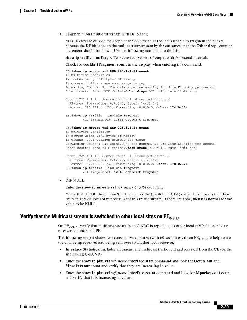
Chapter 2 Troubleshooting mVPNs Section 4: Verifying mVPN Data Flow
• Fragmentation (multicast stream with DF bit set)
MTU issues are outside the scope of the document. If the PE is unable to fragment the packet because the DF bit is set on the multicast stream sent by the customer, then the Other drops counter increment should be shown. Use the following command to do this:
show ip traffic | inc frag <-Two consecutive sets of output with 30 second intervals
Check for couldn't fragment count in the display when entering this command.
PE1#show ip mroute vrf RED 225.1.1.10 count IP Multicast Statistics17 routes using 8392 bytes of memory12 groups, 0.41 average sources per groupForwarding Counts: Pkt Count/Pkts per second/Avg Pkt Size/Kilobits per secondOther counts: Total/RPF failed/Other drops(OIF-null, rate-limit etc)
Group: 225.1.1.10, Source count: 1, Group pkt count: 0 RP-tree: Forwarding: 0/0/0/0, Other: 344/344/0 Source: 192.168.1.1/32, Forwarding: 0/0/0/0, Other: 174/0/174
PE1#show ip traffic | include fragment 414 fragmented, 12936 couldn't fragment
PE1#show ip mroute vrf RED 225.1.1.10 count IP Multicast Statistics17 routes using 8392 bytes of memory12 groups, 0.41 average sources per groupForwarding Counts: Pkt Count/Pkts per second/Avg Pkt Size/Kilobits per secondOther counts: Total/RPF failed/Other drops(OIF-null, rate-limit etc)
Group: 225.1.1.10, Source count: 1, Group pkt count: 0 RP-tree: Forwarding: 0/0/0/0, Other: 344/344/0 Source: 192.168.1.1/32, Forwarding: 0/0/0/0, Other: 178/0/178PE1#show ip traffic | include fragment 414 fragmented, 12948 couldn't fragment
• OIF NULL
Enter the show ip mroute vrf vrf_name C-GPA command
Verify that the OIL has a non-NULL value for the (C-SRC, C-GPA) entry. This ensures that there are receivers on local or remote PEs for this traffic stream. If there are none, then it is normal for the value to be NULL.
Verify that the Multicast stream is switched to other local sites on PEC-SRC
On PEC-SRC, verify that multicast stream from C-SRC is replicated to other local mVPN sites having receivers on the same PE.
The following output shows two consecutive captures (with 60 secs interval) on PEC-SRC to help relate the data being received and being sent over to another local receiver.
• Interface Statistics: Includes all unicast and multicast traffic sent and received from the CE (on the site having C-RCVR)
• Enter the show ip pim vrf vrf_name interface stats command and look for Octets out and Mpackets out count and verify that they are increasing in value.
• Enter the show ip pim vrf vrf_name interface count command and look for Mpackets out count and verify that it is increasing in value.
2-89Multicast VPN Troubleshooting Guide
OL-10380-01
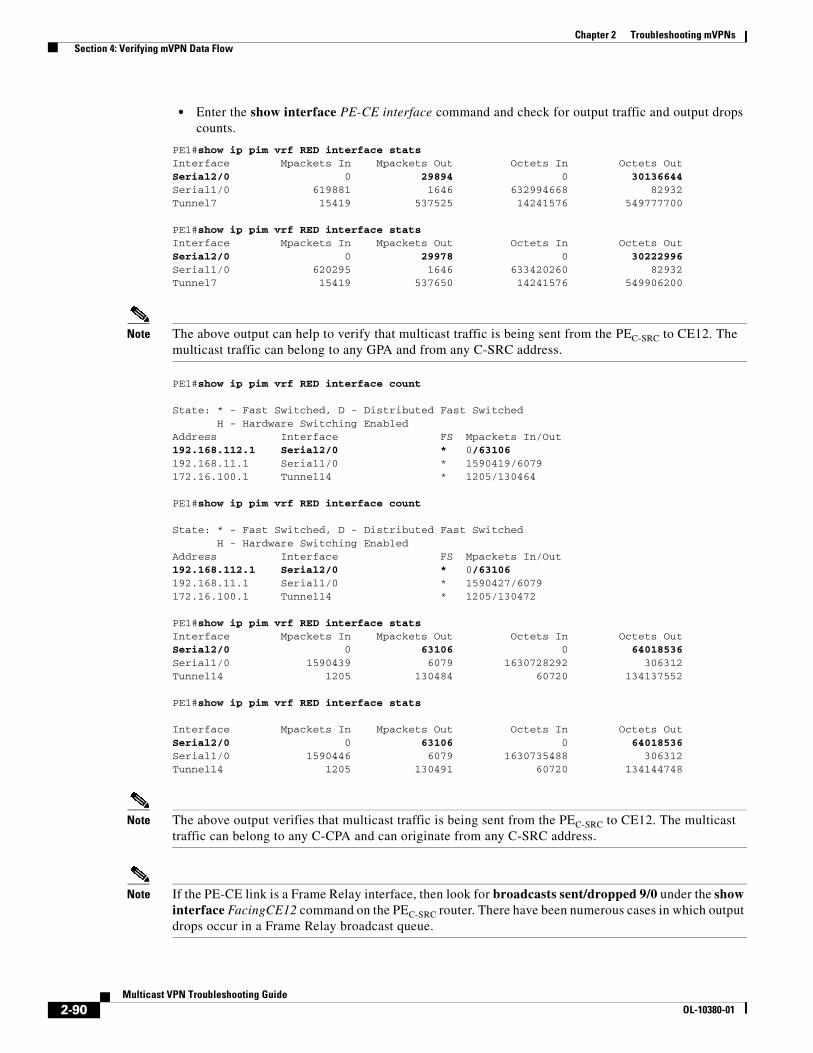
Chapter 2 Troubleshooting mVPNs Section 4: Verifying mVPN Data Flow
• Enter the show interface PE-CE interface command and check for output traffic and output drops counts.
PE1#show ip pim vrf RED interface stats Interface Mpackets In Mpackets Out Octets In Octets OutSerial2/0 0 29894 0 30136644Serial1/0 619881 1646 632994668 82932Tunnel7 15419 537525 14241576 549777700
PE1#show ip pim vrf RED interface stats Interface Mpackets In Mpackets Out Octets In Octets OutSerial2/0 0 29978 0 30222996Serial1/0 620295 1646 633420260 82932Tunnel7 15419 537650 14241576 549906200
Note The above output can help to verify that multicast traffic is being sent from the PEC-SRC to CE12. The multicast traffic can belong to any GPA and from any C-SRC address.
PE1#show ip pim vrf RED interface count
State: * - Fast Switched, D - Distributed Fast Switched H - Hardware Switching EnabledAddress Interface FS Mpackets In/Out192.168.112.1 Serial2/0 * 0/63106192.168.11.1 Serial1/0 * 1590419/6079172.16.100.1 Tunnel14 * 1205/130464
PE1#show ip pim vrf RED interface count
State: * - Fast Switched, D - Distributed Fast Switched H - Hardware Switching EnabledAddress Interface FS Mpackets In/Out192.168.112.1 Serial2/0 * 0/63106192.168.11.1 Serial1/0 * 1590427/6079172.16.100.1 Tunnel14 * 1205/130472
PE1#show ip pim vrf RED interface stats Interface Mpackets In Mpackets Out Octets In Octets OutSerial2/0 0 63106 0 64018536Serial1/0 1590439 6079 1630728292 306312Tunnel14 1205 130484 60720 134137552
PE1#show ip pim vrf RED interface stats
Interface Mpackets In Mpackets Out Octets In Octets OutSerial2/0 0 63106 0 64018536Serial1/0 1590446 6079 1630735488 306312Tunnel14 1205 130491 60720 134144748
Note The above output verifies that multicast traffic is being sent from the PEC-SRC to CE12. The multicast traffic can belong to any C-CPA and can originate from any C-SRC address.
Note If the PE-CE link is a Frame Relay interface, then look for broadcasts sent/dropped 9/0 under the show interface FacingCE12 command on the PEC-SRC router. There have been numerous cases in which output drops occur in a Frame Relay broadcast queue.
2-90Multicast VPN Troubleshooting Guide
OL-10380-01

Chapter 2 Troubleshooting mVPNs Section 4: Verifying mVPN Data Flow
Verifying that the Traffic is being Received on PEC-RCVR over the Global Default MDT Group Entry
Enter the show ip mroute mdt-GPA command on PEC-RCVR.Verify that Z flag is set on the (PEC-SRC, mdt-GPA) entry if available or (*,C-GPA) entry. Use the following output to verify that traffic is received and the counts correspond to what is being sent from PEC-SRC:
show ip mroute mdt-GPA active 1
Two consecutive captures 60 seconds apart
show ip mroute mdt-GPA count
show interface tunnel X
The following example shows the output of the show ip mroute command:
PE3#show ip mroute 239.0.0.10 active 1Active IP Multicast Sources - sending >= 1 kbpsGroup: 239.0.0.10, (?) Source: 172.16.100.1 (?) Rate: 3 pps/26 kbps(1sec), 26 kbps(last 0 secs), 5 kbps(life avg)
PE3#show ip mroute 239.0.0.10 countIP Multicast Statistics11 routes using 5776 bytes of memory5 groups, 1.20 average sources per groupForwarding Counts: Pkt Count/Pkts per second/Avg Pkt Size/Kilobits per secondOther counts: Total/RPF failed/Other drops(OIF-null, rate-limit etc)
Group: 239.0.0.10, Source count: 3, Group pkt count: 3991374 RP-tree: Forwarding: 0/0/0/0, Other: 0/0/0 Source: 172.16.100.1/32, Forwarding: 3861857/3/1042/26, Other: 3861857/0/0 Source: 172.16.100.2/32, Forwarding: 87006/1/242/0, Other: 87006/0/0 Source: 172.16.100.3/32, Forwarding: 42511/0/76/0, Other: 42515/0/4
PE3#show ip mroute 239.0.0.10 countIP Multicast Statistics11 routes using 5776 bytes of memory5 groups, 1.20 average sources per groupForwarding Counts: Pkt Count/Pkts per second/Avg Pkt Size/Kilobits per secondOther counts: Total/RPF failed/Other drops(OIF-null, rate-limit etc)
Group: 239.0.0.10, Source count: 3, Group pkt count: 3991415 RP-tree: Forwarding: 0/0/0/0, Other: 0/0/0 Source: 172.16.100.1/32, Forwarding: 3861896/3/1042/26, Other: 3861896/0/0 Source: 172.16.100.2/32, Forwarding: 87006/0/242/0, Other: 87006/0/0 Source: 172.16.100.3/32, Forwarding: 42513/0/76/0, Other: 42517/0/4
PE3#show int tunnel 0 | include drop|packet Checksumming of packets disabled, fast tunneling enabled Input queue: 0/75/0/0 (size/max/drops/flushes); Total output drops: 0 5 minute input rate 25000 bits/sec, 3 packets/sec 5 minute output rate 0 bits/sec, 0 packets/sec 4198720 packets input, 19321738 bytes, 0 no buffer 42526 packets output, 3262530 bytes, 0 underruns
PE3#show int tunnel 0 | include drop|packet Checksumming of packets disabled, fast tunneling enabled Input queue: 0/75/0/0 (size/max/drops/flushes); Total output drops: 0 5 minute input rate 25000 bits/sec, 3 packets/sec 5 minute output rate 0 bits/sec, 0 packets/sec 4198789 packets input, 19388954 bytes, 0 no buffer 42526 packets output, 3262530 bytes, 0 underruns
2-91Multicast VPN Troubleshooting Guide
OL-10380-01

Chapter 2 Troubleshooting mVPNs Section 4: Verifying mVPN Data Flow
Note The (PE C-SRC, mdt-GPA) entry might not be seen on PEC-RCVR if multicast in the SP-Core is set for bidir or spt threshold-infinity is configured on all the PEs. In such a case, the best option is to track the counters on the RP-tree.
Failure Scenario: Traffic Not Being Received on PEC-RCVR over the Global default MDT Entry
If we do not receive the multicast traffic stream over the default mdt-GPA, trace the physical path between PEC-SRC and PEC-RCVR identify all the hops (P or PE routers) and find out if any of the intermediate hops is dropping the stream.
Use the mtrace command for troubleshooting:
PE3# mtrace <PEC-Src> < PEC-Rcvr> [mdt-GPA]
PE3# mtrace <PEC-Src>
For more information about the mtrace command, refer to Using the Mtrace Tool in Troubleshooting Multicast Issues, page 3-7.
Note Use default mdt source IP addresses for PEC-SRC and PEC-RCVR.
The following example shows output of the mtrace command:
PE3#mtrace 172.16.100.1 172.16.100.3 239.0.0.10Type escape sequence to abort.Mtrace from 172.16.100.1 to 172.16.100.3 via group 239.0.0.10From source (?) to destination (?)Querying full reverse path... 0 172.16.100.3-1 172.16.100.3 PIM [172.16.100.1/32]-2 172.16.3.13 PIM [172.16.100.1/32]-3 172.16.13.11 PIM [172.16.100.1/32]-4 172.16.1.1 PIM [172.16.100.1/32]-5 172.16.100.1
Jump on each hop from PEC-SRC to PEC-RCVR for verifying that the forwarding counts are increasing in show ip mroute mdt-GPA command (two consecutive sets of output 60 seconds apart).
The following example shows output from a P router (172.16.13.11):
P11#show ip mroute 239.0.0.10 count IP Multicast Statistics15 routes using 7704 bytes of memory7 groups, 1.14 average sources per groupForwarding Counts: Pkt Count/Pkts per second/Avg Pkt Size/Kilobits per secondOther counts: Total/RPF failed/Other drops(OIF-null, rate-limit etc)
Group: 239.0.0.10, Source count: 3, Group pkt count: 3962805 RP-tree: Forwarding: 3/0/74/0, Other: 3/0/0 Source: 172.16.100.1/32, Forwarding: 3869629/3/1042/25, Other: 3869629/0/0 Source: 172.16.100.2/32, Forwarding: 65000/1/301/0, Other: 65656/656/0 Source: 172.16.100.3/32, Forwarding: 28173/1/76/0, Other: 28173/0/0
P11#show ip mroute 239.0.0.10 count IP Multicast Statistics15 routes using 7704 bytes of memory7 groups, 1.14 average sources per groupForwarding Counts: Pkt Count/Pkts per second/Avg Pkt Size/Kilobits per secondOther counts: Total/RPF failed/Other drops(OIF-null, rate-limit etc)
2-92Multicast VPN Troubleshooting Guide
OL-10380-01
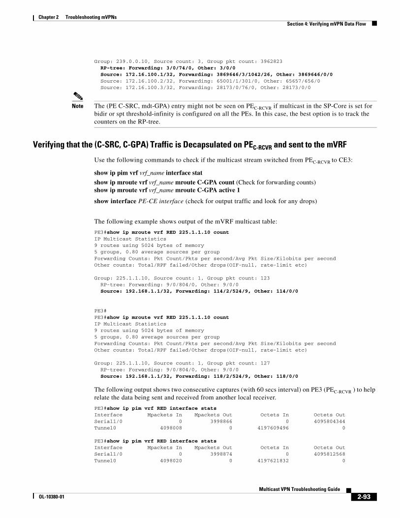
Chapter 2 Troubleshooting mVPNs Section 4: Verifying mVPN Data Flow
Group: 239.0.0.10, Source count: 3, Group pkt count: 3962823 RP-tree: Forwarding: 3/0/74/0, Other: 3/0/0 Source: 172.16.100.1/32, Forwarding: 3869646/3/1042/26, Other: 3869646/0/0 Source: 172.16.100.2/32, Forwarding: 65001/1/301/0, Other: 65657/656/0 Source: 172.16.100.3/32, Forwarding: 28173/0/76/0, Other: 28173/0/0
Note The (PE C-SRC, mdt-GPA) entry might not be seen on PEC-RCVR if multicast in the SP-Core is set for bidir or spt threshold-infinity is configured on all the PEs. In this case, the best option is to track the counters on the RP-tree.
Verifying that the (C-SRC, C-GPA) Traffic is Decapsulated on PEC-RCVR and sent to the mVRF
Use the following commands to check if the multicast stream switched from PEC-RCVR to CE3:
show ip pim vrf vrf_name interface stat
show ip mroute vrf vrf_name mroute C-GPA count (Check for forwarding counts) show ip mroute vrf vrf_name mroute C-GPA active 1
show interface PE-CE interface (check for output traffic and look for any drops)
The following example shows output of the mVRF multicast table:
PE3#show ip mroute vrf RED 225.1.1.10 count IP Multicast Statistics9 routes using 5024 bytes of memory5 groups, 0.80 average sources per groupForwarding Counts: Pkt Count/Pkts per second/Avg Pkt Size/Kilobits per secondOther counts: Total/RPF failed/Other drops(OIF-null, rate-limit etc)
Group: 225.1.1.10, Source count: 1, Group pkt count: 123 RP-tree: Forwarding: 9/0/804/0, Other: 9/0/0 Source: 192.168.1.1/32, Forwarding: 114/2/524/9, Other: 114/0/0
PE3#PE3#show ip mroute vrf RED 225.1.1.10 count IP Multicast Statistics9 routes using 5024 bytes of memory5 groups, 0.80 average sources per groupForwarding Counts: Pkt Count/Pkts per second/Avg Pkt Size/Kilobits per secondOther counts: Total/RPF failed/Other drops(OIF-null, rate-limit etc)
Group: 225.1.1.10, Source count: 1, Group pkt count: 127 RP-tree: Forwarding: 9/0/804/0, Other: 9/0/0 Source: 192.168.1.1/32, Forwarding: 118/2/524/9, Other: 118/0/0
The following output shows two consecutive captures (with 60 secs interval) on PE3 (PEC-RCVR ) to help relate the data being sent and received from another local receiver.
PE3#show ip pim vrf RED interface stats Interface Mpackets In Mpackets Out Octets In Octets OutSerial1/0 0 3998866 0 4095804344Tunnel0 4098008 0 4197609496 0
PE3#show ip pim vrf RED interface stats Interface Mpackets In Mpackets Out Octets In Octets OutSerial1/0 0 3998874 0 4095812568Tunnel0 4098020 0 4197621832 0
2-93Multicast VPN Troubleshooting Guide
OL-10380-01

Chapter 2 Troubleshooting mVPNs Section 4: Verifying mVPN Data Flow
Note The above output verifies that multicast traffic is being sent from PE3 (PEC-RCVR) to CE3. The multicast traffic can belong to any C- GPA and can originate from any C-SRC address.
Note If the PE-CE link is a Frame-Relay interface, check for broadcasts sent/dropped 9/0 under the show interface interface facing CE12 command on the PEC-SRC router. There have been numerous cases in which the output drops occur in the Frame Relay broadcast queue.
Sample Failure Scenario
If the traffic counters are not incrementing, the router might be dropping the packets due to TTL issues.
Step 1 Use the show ip pim vrf vrf_name interface stats command to view the traffic counters and check for packet drops. The (C-SRC, C-GPA) entry might be missing in show ip mroute vrf vrf_name CGPA count.
PE3#show ip mroute vrf RED 225.1.1.3 count IP Multicast Statistics8 routes using 4580 bytes of memory4 groups, 1.00 average sources per groupForwarding Counts: Pkt Count/Pkts per second/Avg Pkt Size/Kilobits per secondOther counts: Total/RPF failed/Other drops(OIF-null, rate-limit etc)
Group: 225.1.1.3, Source count: 1, Group pkt count: 3934 RP-tree: Forwarding: 1/0/1028/0, Other: 8/0/7 Source: 192.168.2.1/32, Forwarding: 3933/0/1028/0, Other: 3996/0/63
PE3#show ip mroute vrf RED 225.1.1.3 count IP Multicast Statistics8 routes using 4580 bytes of memory4 groups, 1.00 average sources per groupForwarding Counts: Pkt Count/Pkts per second/Avg Pkt Size/Kilobits per secondOther counts: Total/RPF failed/Other drops(OIF-null, rate-limit etc)
Group: 225.1.1.3, Source count: 1, Group pkt count: 3934 RP-tree: Forwarding: 1/0/1028/0, Other: 8/0/7 Source: 192.168.2.1/32, Forwarding: 3933/0/1028/0, Other: 4024/0/91
PE3#show ip pim vrf RED interface count
State: * - Fast Switched, D - Distributed Fast Switched H - Hardware Switching EnabledAddress Interface FS Mpackets In/Out192.168.33.1 Serial1/0 * 0/4774568172.16.100.3 Tunnel3 * 949805/0
PE3#show ip pim vrf RED interface count
State: * - Fast Switched, D - Distributed Fast Switched H - Hardware Switching EnabledAddress Interface FS Mpackets In/Out192.168.33.1 Serial1/0 * 0/4774568172.16.100.3 Tunnel3 * 949863/0
2-94Multicast VPN Troubleshooting Guide
OL-10380-01

Chapter 2 Troubleshooting mVPNs Section 4: Verifying mVPN Data Flow
PE3#show ip pim vrf RED interface stat
Interface Mpackets In Mpackets Out Octets In Octets OutSerial1/0 0 4774569 0 586481216Tunnel3 949884 0 968708852 0
PE3#show ip pim vrf RED interface stat
Interface Mpackets In Mpackets Out Octets In Octets OutSerial1/0 0 4774569 0 586481216Tunnel3 949900 0 968725300 0PE3#
Step 2 Check for TTL issues by issuing the show ip traffic | inc bad hop command:
PE3#show ip traffic | include bad hop 0 format errors, 0 checksum errors, 23456 bad hop count
PE3#show ip traffic | include bad hop 0 format errors, 0 checksum errors, 23456 bad hop count
Step 3 Note that you could soon lose the (C-SRC, C-GPA) entry from PE3:
PE3#show ip mroute vrf RED 225.1.1.3 count IP Multicast Statistics6 routes using 3676 bytes of memory4 groups, 0.50 average sources per groupForwarding Counts: Pkt Count/Pkts per second/Avg Pkt Size/Kilobits per secondOther counts: Total/RPF failed/Other drops(OIF-null, rate-limit etc)
Group: 225.1.1.3, Source count: 0, Group pkt count: 1 RP-tree: Forwarding: 1/0/1028/0, Other: 136/0/135
PE3#show ip pim vrf RED interface ser1/0 detail Serial1/0 is up, line protocol is up Internet address is 192.168.33.1/24 Multicast switching: fast Multicast packets in/out: 0/4774577 Multicast boundary: not set Multicast TTL threshold: 2 PIM: enabled PIM version: 2, mode: sparse PIM DR: 0.0.0.0 PIM neighbor count: 1 PIM Hello/Query interval: 30 seconds PIM NBMA mode: disabled PIM ATM multipoint signalling: disabled PIM domain border: disabled PIM neighbors rpf proxy capable: TRUE Multicast Tagswitching: disabled
2-95Multicast VPN Troubleshooting Guide
OL-10380-01

Chapter 2 Troubleshooting mVPNs Section 4: Verifying mVPN Data Flow
2-96Multicast VPN Troubleshooting Guide
OL-10380-01
OL-10380-01
C H A P T E R 3
Using Device Instrumentation for mVPN TroubleshootingDevice Instrumentation (DI) is the set of Cisco IOS embedded tools that allow for an intelligent, remote, and, in some cases, proactive management of network devices. This section presents the various DI features you can use when troubleshooting mVPNs.
Note that the focus in this section is on mVPN-specific features and not on the whole set of DI tools available for IP multicast.
The following features are covered:
• Syslogs
• mVPN Management Information Base (MIB)
• VPN-MIB
• Other PIM, IGMP, IGP, interface, and BGP related MIBs
• Multicast NetFlow (egress and ingress) cache and data export
• mtrace tool
• mrinfo tool
• Ping tool
The range of possible mVPN issues are often caused either by misconfigurations, changes of design, or in some cases by platform, or Cisco IOS-specific behaviors.
Deploying and leveraging DI allows you to passively monitor and proactively retrieve information when necessary about the mVPN setup and potential configuration changes. The following sections describe the benefits available by using the DI.
Using DI When Adding an mVPN Customer SiteWhen you fully configure an mVPN for the first time or add a customer site, you can watch for Syslog messages, along with the show command output. This enables you to monitor events and look for mVPN-related messages (for example, MTI interface UP, PE-PE neighbors UP over the MTI, PE-CE neighbor UP over the mVRF interface, and DR election over the MTI).
*Aug 31 19:30:17.331: %BGP-5-ADJCHANGE: neighbor 172.16.100.100 Up *Aug 31 19:32:06.523: %PIM-5-DRCHG: DR change from neighbor 0.0.0.0 to 172.16.100.3 on interface Tunnel0 (vrf RED)
3-1Multicast VPN Troubleshooting Guide
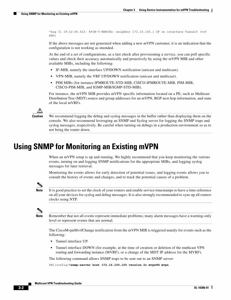
Chapter 3 Using Device Instrumentation for mVPN Troubleshooting Using SNMP for Monitoring an Existing mVPN
*Aug 31 19:32:06.523: %PIM-5-NBRCHG: neighbor 172.16.100.1 UP on interface Tunnel0 (vrf RED)
If the above messages are not generated when adding a new mVPN customer, it is an indication that the configuration is not working as intended.
At the end of a set of configurations, as a last check after provisioning a service, you can poll specific values and check their accuracy automatically and proactively by using the mVPN MIB and other available MIBs, including the following:
• IF-MIB, namely the interface UP/DOWN notification (unicast and multicast).
• VPN-MIB, namely the VRF UP/DOWN notification (unicast and multicast).
• PIM MIBs (for instance IPMROUTE-STD-MIB, CISCO-IPMROUTE-MIB, PIM-MIB, CISCO-PIM-MIB, and IGMP-MIB/IGMP-STD-MIB).
For instance, the mVPN MIB provides mVPN specific information located on a PE, such as Multicast Distribution Tree (MDT) source and group addresses for an mVPN, BGP next hop information, and state of the local mVRFs.
Caution We recommend logging the debug and syslog messages in the buffer rather than displaying them on the console. We also recommend leveraging an SNMP and Syslog server for logging the SNMP traps and syslog messages, respectively. Be careful when turning on debugs in a production environment so as to not bring the router down.
Using SNMP for Monitoring an Existing mVPNWhen an mVPN setup is up and running, We highly recommend that you keep monitoring the various events, turning on and logging SNMP notifications for the appropriate MIBs, and logging syslog messages for later retrieval.
Monitoring the events allows for early detection of potential issues, and logging events allows you to consult the history of events and changes, and to track the potential causes of a problem.
Note It is good practice to set the clock of your routers and enable service timestamps to have a time reference on all your devices for syslog and debug messages. It is also strongly recommended to sync up all routers clocks using NTP.
Note Remember that not all events represent immediate problems; many alarm messages have a warning-only level or represent events that are normal.
The CiscoMvpnMvrfChange notification from the mVPN MIB is triggered mainly for events such as the following:
• Tunnel interface UP.
• Tunnel interface DOWN (for example, at the time of creation or deletion of the multicast VPN routing and forwarding instance (MVRF), or a change of the MDT IP address for the MVRF).
The following command allows SNMP traps to be sent out to an SNMP server:
PE1(config)#snmp-server host 172.16.100.100 version 2c mvpnTG mvpn
3-2Multicast VPN Troubleshooting Guide
OL-10380-01
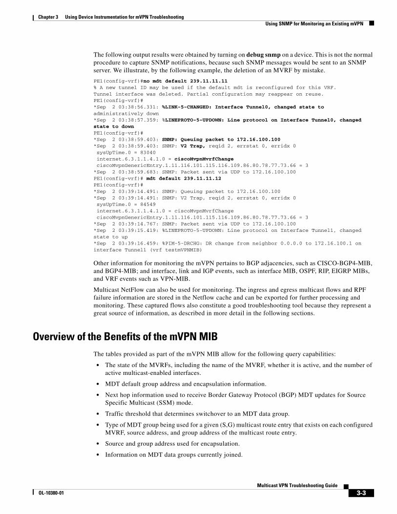
Chapter 3 Using Device Instrumentation for mVPN Troubleshooting Using SNMP for Monitoring an Existing mVPN
The following output results were obtained by turning on debug snmp on a device. This is not the normal procedure to capture SNMP notifications, because such SNMP messages would be sent to an SNMP server. We illustrate, by the following example, the deletion of an MVRF by mistake.
PE1(config-vrf)#no mdt default 239.11.11.11 % A new tunnel ID may be used if the default mdt is reconfigured for this VRF.Tunnel interface was deleted. Partial configuration may reappear on reuse.PE1(config-vrf)#*Sep 2 03:38:56.331: %LINK-5-CHANGED: Interface Tunnel0, changed state to administratively down*Sep 2 03:38:57.359: %LINEPROTO-5-UPDOWN: Line protocol on Interface Tunnel0, changed state to downPE1(config-vrf)#*Sep 2 03:38:59.403: SNMP: Queuing packet to 172.16.100.100*Sep 2 03:38:59.403: SNMP: V2 Trap, reqid 2, errstat 0, erridx 0 sysUpTime.0 = 83040 internet.6.3.1.1.4.1.0 = ciscoMvpnMvrfChange ciscoMvpnGenericEntry.1.11.116.101.115.116.109.86.80.78.77.73.66 = 3*Sep 2 03:38:59.683: SNMP: Packet sent via UDP to 172.16.100.100PE1(config-vrf)# mdt default 239.11.11.12 PE1(config-vrf)#*Sep 2 03:39:14.491: SNMP: Queuing packet to 172.16.100.100*Sep 2 03:39:14.491: SNMP: V2 Trap, reqid 2, errstat 0, erridx 0 sysUpTime.0 = 84549 internet.6.3.1.1.4.1.0 = ciscoMvpnMvrfChange ciscoMvpnGenericEntry.1.11.116.101.115.116.109.86.80.78.77.73.66 = 3*Sep 2 03:39:14.767: SNMP: Packet sent via UDP to 172.16.100.100*Sep 2 03:39:15.419: %LINEPROTO-5-UPDOWN: Line protocol on Interface Tunnel1, changed state to up*Sep 2 03:39:16.459: %PIM-5-DRCHG: DR change from neighbor 0.0.0.0 to 172.16.100.1 on interface Tunnel1 (vrf testmVPNMIB)
Other information for monitoring the mVPN pertains to BGP adjacencies, such as CISCO-BGP4-MIB, and BGP4-MIB; and interface, link and IGP events, such as interface MIB, OSPF, RIP, EIGRP MIBs, and VRF events such as VPN-MIB.
Multicast NetFlow can also be used for monitoring. The ingress and egress multicast flows and RPF failure information are stored in the Netflow cache and can be exported for further processing and monitoring. These captured flows also constitute a good troubleshooting tool because they represent a great source of information, as described in more detail in the following sections.
Overview of the Benefits of the mVPN MIB The tables provided as part of the mVPN MIB allow for the following query capabilities:
• The state of the MVRFs, including the name of the MVRF, whether it is active, and the number of active multicast-enabled interfaces.
• MDT default group address and encapsulation information.
• Next hop information used to receive Border Gateway Protocol (BGP) MDT updates for Source Specific Multicast (SSM) mode.
• Traffic threshold that determines switchover to an MDT data group.
• Type of MDT group being used for a given (S,G) multicast route entry that exists on each configured MVRF, source address, and group address of the multicast route entry.
• Source and group address used for encapsulation.
• Information on MDT data groups currently joined.
3-3Multicast VPN Troubleshooting Guide
OL-10380-01

Chapter 3 Using Device Instrumentation for mVPN Troubleshooting Using DI to Optimize Troubleshooting Steps
• Information on mVPN-specific MDT tunnels present in the device.
• Trap notification enabled on the router.
Using DI to Optimize Troubleshooting StepsMulticast Netflow, mtrace, mrinfo, and ping can be very helpful in understanding what is happening in the network, because they allow the users to visualize the packet path and determine on which router the problem exists.
Naturally, as mentioned throughout this document, show commands are also key to troubleshooting an mVPN setup, especially the packet counters and mrouter counters, which allow us to visualize the data flows and their evolution.
Multicast NetFlowYou can leverage multicast NetFlow for monitoring the various multicast flows within the core or at the mVRF level. Retrieving the information while troubleshooting may help solve problems more quickly, because the stored information contain the history of events, and the cached information is constantly updated.
In general, NetFlow is used for providing usage and billing information for security reasons (monitoring). Multicast NetFlow allows for visualizing the various flows and capturing Reverse Path Forwarding (RPF) failure statistics, which allows you to check on the traffic and visualize where the flow(s) stopped.
Information can be exported if version 9 of NetFlow is used. With version 5, the information can be visualized locally in the cache of the router.
• For an ingress flow, the cache logs the flows as source IP address, group address, and average of replicated packets, which is the average duplication factor (in packets and in bytes, noted IPM X Packets, and Y bytes)
• The outgoing flow is accounted for as a separate flow.
routerA#sh ip cache verbose flowIP packet size distribution (192805 total packets): 1-32 64 96 128 160 192 224 256 288 320 352 384 416 448 480 .000 .572 .149 .039 .022 .011 .007 .012 .027 .003 .003 .004 .003 .000 .003
512 544 576 1024 1536 2048 2560 3072 3584 4096 4608 .002 .001 .000 .026 .106 .000 .000 .000 .000 .000 .000
IP Flow Switching Cache, 4456704 bytes 9 active, 65527 inactive, 20 added 3652 ager polls, 0 flow alloc failures Active flows timeout in 30 minutes Inactive flows timeout in 15 secondsIP Sub Flow Cache, 270472 bytes 1 active, 16383 inactive, 0 added, 0 added to flow 0 alloc failures, 0 force free 1 chunk, 0 chunks added last clearing of statistics 00:06:11
Protocol Total Flows Packets Bytes Packets Active(Sec) Idle(Sec)-------- Flows /Sec /Flow /Pkt /Sec /Flow /FlowTCP-other 12 0.0 1 48 0.0 0.0 15.5
3-4Multicast VPN Troubleshooting Guide
OL-10380-01

Chapter 3 Using Device Instrumentation for mVPN Troubleshooting Using DI to Optimize Troubleshooting Steps
UDP-other 9 0.0 1 127 0.0 0.0 15.4Total: 21 0.0 1 74 0.0 0.0 15.5
SrcIf SrcIPaddress DstIf DstIPaddress Pr TOS Flgs PktsPort Msk AS Port Msk AS NextHop B/Pk ActiveIPM: OPkts OBytes
Se4/0:0 1.192.3.100 Fa1/0 1.1.160.100 06 68 18 78K0017 /0 0 84E5 /0 0 0.0.0.0 53 920.3Se4/0:0 1.199.240.2 Null 224.0.0.10 58 C0 10 2010000 /0 0 0000 /0 0 0.0.0.0 100 928.3IPM: 0 0
The IPM header lines in the preceding example confirm that Multicast NetFlow is supported. Also note that in this case the router does not need to duplicate the multicast traffic, which is why the IPM counters show a value of 0. The above last entry shows one multicast flow seen from 1.199.240.2 received on Se4 destined for 224.0.0.10 that was terminated in the router.
Multicast Netflow: RPF Monitoring
You can obtain statistics about RPF failures by leveraging Multicast NetFlow, which provides statistics to account for all packets that fail the RPF check and that are dropped. This helps to identify patterns and to narrow down the list of possible problems.
The following commands turn on multicast egress and ingress NetFlow. Note that ingress NetFlow does not appear on the running configuration after being enabled.
• Multicast NetFlow
(Global config)#ip multicast netflow rpf-failure
• Configuration per interface:
#ip route-cache flow#ip multicast netflow egresssh ip cache verbose flow
Note NetFlow accounts for only fast switching or multicast distributed fast switching (MDFS)-switched packets, but not for process-switched flows.
Multicast Netflow: Performance and Memory Considerations
Be aware that egress NetFlow slightly affects the performance of a router device. There is some memory impact because information is stored in the cache of the router. Note that Multicast NetFlow adds two more fields to the traditional flow entry. For more information, refer to the following URL: http://www.cisco.com/en/US/products/ps6350/products_configuration_guide _chapter09186a0080438df4.html
Using mrinfo for Troubleshooting Multicast IssuesThe mrinfo command shows multicast neighbor router information, router capabilities and code version, multicast interface information, TTL thresholds, metrics, protocol, and status. It is useful when you need to verify multicast neighbors, and confirm that bi-directional neighbor adjacency exists.
3-5Multicast VPN Troubleshooting Guide
OL-10380-01

Chapter 3 Using Device Instrumentation for mVPN Troubleshooting Using DI to Optimize Troubleshooting Steps
The syntax for the mrinfo command is as follows:
mrinfo [hostname-or-address] [source-address-or-interface]
The mrinfo command requests the configuration information from the multicast router, which can be either an IP address or a system name. The mrinfo command sends out the ASK_NEIGHBORS IGMP message to the specified multicast router. When the router receives the request, it responds with the version number and a list of their neighboring multicast router addresses. Depending on the mrinfo version number, the response to the mrinfo request may contain additional information such as metrics, thresholds, and flags from the multicast router sending back its configuration information. If the multicast router is not specified, the request is sent to the local router. If source-address-or-interface is specified, this becomes the source address used on mrinfo requests. When it is omitted, the source address is based on the outbound interface for the destination.
The configuration information for each interface is displayed in the following format:
multicast-router [IOS version mainline] [FLAG]
interface_addr -> neighbor_addr (neighbor_name) [metrics/thresh/flags]
If there are multiple neighbor routers on one interface, they are all reported in the output.
The possible FLAG values are as follows:
• P—Prune-capable
• M—mtrace-capable
• S—SNMP-capable
• A—Auto-RP-capable
The possible interface flag values are as follows:
• Leaf—There is no PIM neighbor on the interface.
• Querier—The local router is the querier of the subnet.
• PIM—If the neighbor is a PIM neighbor.
• Tunnel—Neighbors are reached via tunnel.
The following example shows output for the mrinfo command (refer to Figure 1-1 on page 1-2 for the topology):
PE1 querying CE1:
PEC-SRC#mrinfo vrf RED 192.168.11.2 serial 1/0192.168.11.2 [version 12.0] [flags: PMA]:192.168.1.2 -> 0.0.0.0 [1/0/pim/querier/leaf]192.168.0.1 -> 0.0.0.0 [1/0/pim/querier/leaf]192.168.11.2 -> 192.168.11.1 [1/0/pim]
PE1 querying CE2:
PEC-SRC#mrinfo vrf RED 192.168.22.2 serial 1/0192.168.22.2 [version 12.0] [flags: PMA]:192.168.2.2 -> 0.0.0.0 [1/0/pim/querier/leaf]192.168.202.2 -> 192.168.202.202 [1/0/pim]192.168.22.2 -> 192.168.22.1 [1/0/pim]
PE1 querying PE2:
PEC-SRC#mrinfo vrf RED 192.168.22.1 serial 1/0192.168.22.1 [version 12.0] [flags: PMA]:192.168.22.1 -> 192.168.22.2 [1/0/pim]192.168.212.1 -> 0.0.0.0 [1/0/pim/down/leaf]
3-6Multicast VPN Troubleshooting Guide
OL-10380-01

Chapter 3 Using Device Instrumentation for mVPN Troubleshooting Using DI to Optimize Troubleshooting Steps
172.16.100.2 -> 172.16.100.1 [1/0/tunnel/pim]172.16.100.2 -> 172.16.100.3 [1/0/tunnel/pim]
CE1 querying PE1:
CE1#mrinfo 192.168.11.1192.168.11.1 [version 12.0] [flags: PMA]:192.168.11.1 -> 192.168.11.2 [1/0/pim]192.168.112.1 -> 192.168.112.2 [1/0/pim]172.16.100.1 -> 172.16.100.3 [1/0/tunnel/pim]172.16.100.1 -> 172.16.100.2 [1/0/tunnel/pim]
CE1 querying CE2 and CE3:
CE1#mrinfo 192.168.100.3192.168.100.3 [version 12.0] [flags: PMA]:192.168.3.2 -> 0.0.0.0 [1/0/pim/querier/leaf]192.168.33.2 -> 192.168.33.1 [1/0/pim]CE1#mrinfo 192.168.100.2192.168.100.2 [version 12.0] [flags: PMA]:192.168.2.2 -> 0.0.0.0 [1/0/pim/querier/leaf]192.168.202.2 -> 192.168.202.202 [1/0/pim]192.168.22.2 -> 192.168.22.1 [1/0/pim]
CE1 querying PE2:
CE1#mrinfo 192.168.22.1192.168.22.1 [version 12.0] [flags: PMA]:192.168.22.1 -> 192.168.22.2 [1/0/pim]192.168.212.1 -> 0.0.0.0 [1/0/pim/down/leaf]172.16.100.2 -> 172.16.100.1 [1/0/tunnel/pim]172.16.100.2 -> 172.16.100.3 [1/0/tunnel/pim]
Service providers can use the ip multicast mrinfo-filter command to prevent the enterprise customers from querying the service provider and finding all PEs in the mVPN.
http://www.cisco.com/en/US/products/sw/iosswrel/ps1839/products_command_reference _chapter09186a008010ea27.html#wp1093149
Using the Mtrace Tool in Troubleshooting Multicast IssuesThe mtrace command shows the multicast path from the source to the receiver. This command traces the path between points in the networks, which shows TTL thresholds and delay at each node. When troubleshooting, use the mtrace command to find where multicast traffic flow stops, to verify the path of multicast traffic, and to identify sub-optimal paths.
The syntax for the mtrace command is as follows: mtrace src IP addr dest IP addr grp addr.
• Multicast packets to the group and traces RPF path from destination back to the source.
• The mtrace command can be used at a completely different router. The source will send the trace results to the issuing router.
• If the group-address is not specified, then the group 244.2.0.1 is used (MBone Audio). In this case, it is called a weak mtrace.
The following examples show how the mtrace command can be used to troubleshoot issues with an mVPN network (refer to Figure 1-1 on page 1-2 for the topology used).
P-RP#mtrace 172.16.100.1 239.0.0.10Type escape sequence to abort.Mtrace from 172.16.100.1 to 172.16.213.200 via group 239.0.0.10
3-7Multicast VPN Troubleshooting Guide
OL-10380-01

Chapter 3 Using Device Instrumentation for mVPN Troubleshooting Using DI to Optimize Troubleshooting Steps
From source (?) to destination (?)Querying full reverse path...0 172.16.213.200-1 172.16.213.200 PIM Reached RP/Core [172.16.100.1/32]-2 172.16.213.13 PIM [172.16.100.1/32]-3 172.16.13.11 PIM [172.16.100.1/32]-4 172.16.1.1 PIM [172.16.100.1/32]
P-RP#mtrace 172.16.100.1Type escape sequence to abort.Mtrace from 172.16.100.1 to 172.16.213.200 via RPFFrom source (?) to destination (?)Querying full reverse path...0 172.16.213.200-1 172.16.213.200 PIM [172.16.100.1/32]-2 172.16.213.13 PIM [172.16.100.1/32]-3 172.16.13.11 PIM [172.16.100.1/32]-4 172.16.1.1 PIM [172.16.100.1/32]-5 172.16.100.1
Traffic Failure Scenarios
The following subsections show traffic failure scenarios on various interfaces.
PIM Disabled on PE1-P11 (on P11 interface)P-RP#mtrace 172.16.100.1Type escape sequence to abort.Mtrace from 172.16.100.1 to 172.16.213.200 via RPFFrom source (?) to destination (?)Querying full reverse path...0 172.16.213.200-1 172.16.213.200 PIM [172.16.100.1/32]-2 172.16.213.13 PIM [172.16.100.1/32]-3 172.16.13.11 None No route
P-RP#mtrace 172.16.100.1 239.0.0.10Type escape sequence to abort.Mtrace from 172.16.100.1 to 172.16.213.200 via group 239.0.0.10From source (?) to destination (?)Querying full reverse path...0 172.16.213.200-1 172.16.213.200 PIM Reached RP/Core [172.16.100.1/32]-2 172.16.213.13 PIM [172.16.100.1/32]-3 172.16.13.11 PIM No route
PIM Static Configuration Missing on P11P-RP#mtrace 172.16.100.1 239.0.0.10Type escape sequence to abort.Mtrace from 172.16.100.1 to 172.16.213.200 via group 239.0.0.10From source (?) to destination (?)Querying full reverse path...0 172.16.213.200-1 172.16.213.200 PIM Reached RP/Core [172.16.100.1/32]-2 172.16.213.13 PIM [172.16.100.1/32]-3 172.16.13.11 PIM [172.16.100.1/32]-4 172.16.1.1 PIM [172.16.100.1/32]
P-RP#mtrace 172.16.100.1Type escape sequence to abort.Mtrace from 172.16.100.1 to 172.16.213.200 via RPF
3-8Multicast VPN Troubleshooting Guide
OL-10380-01

Chapter 3 Using Device Instrumentation for mVPN Troubleshooting Using DI to Optimize Troubleshooting Steps
From source (?) to destination (?)Querying full reverse path...0 172.16.213.200-1 172.16.213.200 PIM [172.16.100.1/32]-2 172.16.213.13 PIM [172.16.100.1/32]-3 172.16.13.11 PIM [172.16.100.1/32]-4 172.16.1.1 PIM [172.16.100.1/32]-5 172.16.100.1
IP Multicast Routing Disabled on P11P-RP#mtrace 172.16.100.1 239.0.0.10Type escape sequence to abort.Mtrace from 172.16.100.1 to 172.16.213.200 via group 239.0.0.10From source (?) to destination (?)Querying full reverse path...0 172.16.213.200-1 172.16.213.200 PIM Reached RP/Core [172.16.100.1/32]-2 172.16.213.13 PIM [172.16.100.1/32]-3 172.16.13.11 None Multicast disabled [172.16.100.1/32]
P-RP#mtrace 172.16.100.1Type escape sequence to abort.Mtrace from 172.16.100.1 to 172.16.213.200 via RPFFrom source (?) to destination (?)Querying full reverse path...0 172.16.213.200-1 172.16.213.200 PIM [172.16.100.1/32]-2 172.16.213.13 PIM [172.16.100.1/32]-3 172.16.13.11 PIM Multicast disabled [172.16.100.1/32]-4 172.16.1.1 PIM [172.16.100.1/32]
PIM Disabled on PE1-P11 (on PE1 Interface)
P-RP#mtrace 172.16.100.1 239.0.0.10Type escape sequence to abort.Mtrace from 172.16.100.1 to 172.16.213.200 via group 239.0.0.10From source (?) to destination (?)Querying full reverse path...0 172.16.213.200-1 172.16.213.200 PIM Reached RP/Core [172.16.100.1/32]-2 172.16.213.13 PIM [172.16.100.1/32]-3 172.16.13.11 PIM [172.16.100.1/32]-4 172.16.1.1 None Multicast disabled [172.16.100.1/32]
P-RP#mtrace 172.16.100.1Type escape sequence to abortMtrace from 172.16.100.1 to 172.16.213.200 via RPFFrom source (?) to destination (?)Querying full reverse path...0 172.16.213.200-1 172.16.213.200 PIM [172.16.100.1/32]-2 172.16.213.13 PIM [172.16.100.1/32]-3 172.16.13.11 PIM [172.16.100.1/32]-4 172.16.1.1 PIM Multicast disabled [172.16.100.1/32]
PEC-SRC#mtrace 172.16.100.200Type escape sequence to abort.Mtrace from 172.16.100.200 to 172.16.1.1 via RPFFrom source (?) to destination (?)Querying full reverse path...0 172.16.1.1-1 172.16.1.1 PIM [172.16.100.200/32]-2 172.16.1.11 PIM [172.16.100.200/32]
3-9Multicast VPN Troubleshooting Guide
OL-10380-01
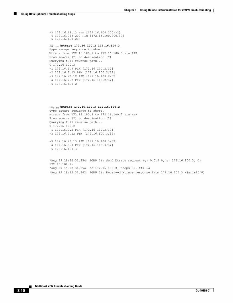
Chapter 3 Using Device Instrumentation for mVPN Troubleshooting Using DI to Optimize Troubleshooting Steps
-3 172.16.13.13 PIM [172.16.100.200/32]-4 172.16.213.200 PIM [172.16.100.200/32]-5 172.16.100.200
PEC-SRC#mtrace 172.16.100.2 172.16.100.3Type escape sequence to abort.Mtrace from 172.16.100.2 to 172.16.100.3 via RPFFrom source (?) to destination (?)Querying full reverse path...0 172.16.100.3-1 172.16.3.3 PIM [172.16.100.2/32]-2 172.16.3.13 PIM [172.16.100.2/32]-3 172.16.23.12 PIM [172.16.100.2/32]-4 172.16.2.2 PIM [172.16.100.2/32]-5 172.16.100.2
PEC-SRC#mtrace 172.16.100.3 172.16.100.2Type escape sequence to abort.Mtrace from 172.16.100.3 to 172.16.100.2 via RPFFrom source (?) to destination (?)Querying full reverse path...0 172.16.100.2-1 172.16.2.2 PIM [172.16.100.3/32]-2 172.16.2.12 PIM [172.16.100.3/32]
-3 172.16.23.13 PIM [172.16.100.3/32]-4 172.16.3.3 PIM [172.16.100.3/32]-5 172.16.100.3
*Aug 29 19:22:31.254: IGMP(0): Send Mtrace request (g: 0.0.0.0, s: 172.16.100.3, d:172.16.100.2)*Aug 29 19:22:31.254: to 172.16.100.2, nhops 32, ttl 64
*Aug 29 19:22:31.362: IGMP(0): Received Mtrace response from 172.16.100.3 (Serial0/0)
3-10Multicast VPN Troubleshooting Guide
OL-10380-01

OL-10380-01
A P P E N D I X A
Sample Configurations for TestbedBelow are sample configurations for the PE, P-RP, C-RP, and RR.
The first set of output is taken for the MDT Bidir setup with P-RP set statically and AutoRP used on the customer network with PIM SM mode.
The second set of output is taken for the MDT PIM SM setup with the same RP and Customer parameters as for BIDIR otherwise.
Note that the RR, C-RP and CEs configurations are the same in the Bidir and PIM-SM test setups.
BIDIR
PE1#sh runBuilding configuration...
Current configuration : 2112 bytes!version 12.0service timestamps debug datetime msecservice timestamps log datetime msecno service password-encryption!hostname PE1!boot-start-markerboot-end-marker!!clock timezone PST -8ip subnet-zeroip cefno ip domain-lookupip vrf RED rd 1:100 route-target export 1:100 route-target import 1:100 mdt default 239.0.0.10! ip multicast-routing ip multicast-routing vrf RED mpls label protocol ldptag-switching tdp router-id Loopback0 force!!!interface Loopback0
A-1Multicast VPN Troubleshooting Guide

Appendix A Sample Configurations for Testbed
ip address 172.16.100.1 255.255.255.255 no ip directed-broadcast ip pim sparse-mode!interface Serial0/0 ip address 172.16.1.1 255.255.255.0 no ip directed-broadcast ip pim sparse-mode no fair-queue!interface Serial1/0 ip vrf forwarding RED ip address 192.168.11.1 255.255.255.0 no ip directed-broadcast ip pim sparse-mode!interface Serial2/0 ip vrf forwarding RED ip address 192.168.112.1 255.255.255.0 no ip directed-broadcast ip pim sparse-mode!router ospf 1 router-id 172.16.100.1 log-adjacency-changes mpls ldp autoconfig network 172.16.0.0 0.0.255.255 area 0!router bgp 1 bgp router-id 172.16.100.1 no bgp default ipv4-unicast bgp log-neighbor-changes neighbor 172.16.100.100 remote-as 1 neighbor 172.16.100.100 update-source Loopback0 ! address-family ipv4 mdtneighbor 172.16.100.100 activate neighbor 172.16.100.100 send-community both exit-address-family ! address-family vpnv4 neighbor 172.16.100.100 activate neighbor 172.16.100.100 send-community both exit-address-family ! address-family ipv4 vrf RED neighbor 192.168.11.2 remote-as 65000 neighbor 192.168.11.2 activate neighbor 192.168.11.2 as-override neighbor 192.168.112.2 remote-as 65000 neighbor 192.168.112.2 activate neighbor 192.168.112.2 as-override no auto-summary no synchronization exit-address-family!ip classless!ip pim bidir-enableip pim rp-address 172.16.100.200 1 override bidirip pim vrf RED autorp listener!access-list 1 permit 239.0.0.0 0.0.0.255!
A-2Multicast VPN Troubleshooting Guide
OL-10380-01

Appendix A Sample Configurations for Testbed
!control-plane!!line con 0 exec-timeout 0 0line aux 0line vty 0 4 privilege level 15 no login!no cns aaa enableend
P-RP#sh runBuilding configuration...
Current configuration : 1199 bytes!version 12.0service timestamps debug datetime msecservice timestamps log datetime msecno service password-encryption!hostname P-RP!boot-start-markerboot-end-marker!!clock timezone PST -8ip subnet-zeroip cefno ip domain-lookupip multicast-routing mpls label protocol ldptag-switching tdp router-id Loopback0 force!!! interface Loopback0 ip address 172.16.100.200 255.255.255.255 no ip directed-broadcast ip pim sparse-mode!interface Serial0/0 ip address 172.16.212.200 255.255.255.0 no ip directed-broadcast ip pim sparse-mode no fair-queue!interface Serial1/0 ip address 172.16.213.200 255.255.255.0 no ip directed-broadcast ip pim sparse-mode!router ospf 1 router-id 172.16.100.200
A-3Multicast VPN Troubleshooting Guide
OL-10380-01

Appendix A Sample Configurations for Testbed
log-adjacency-changes mpls ldp autoconfig network 172.16.0.0 0.0.255.255 area 0!ip classless!ip pim bidir-enableip pim rp-address 172.16.100.200 1 override bidir!access-list 1 permit 239.0.0.0 0.0.0.255!!control-plane!!line con 0 exec-timeout 0 0line aux 0line vty 0 4 privilege level 15 no login!no cns aaa enableend
P-RP#
RR#sh runBuilding configuration...
Current configuration : 1744 bytes!version 12.0service timestamps debug datetime msecservice timestamps log datetime msecno service password-encryption!hostname RR!boot-start-markerboot-end-marker!!clock timezone PST -8ip subnet-zeroip cefno ip domain-lookup!!!interface Loopback0 ip address 172.16.100.100 255.255.255.255 no ip directed-broadcast!interface Serial0/0 ip address 172.16.111.100 255.255.255.0 no ip directed-broadcast no fair-queue!interface Serial1/0
A-4Multicast VPN Troubleshooting Guide
OL-10380-01
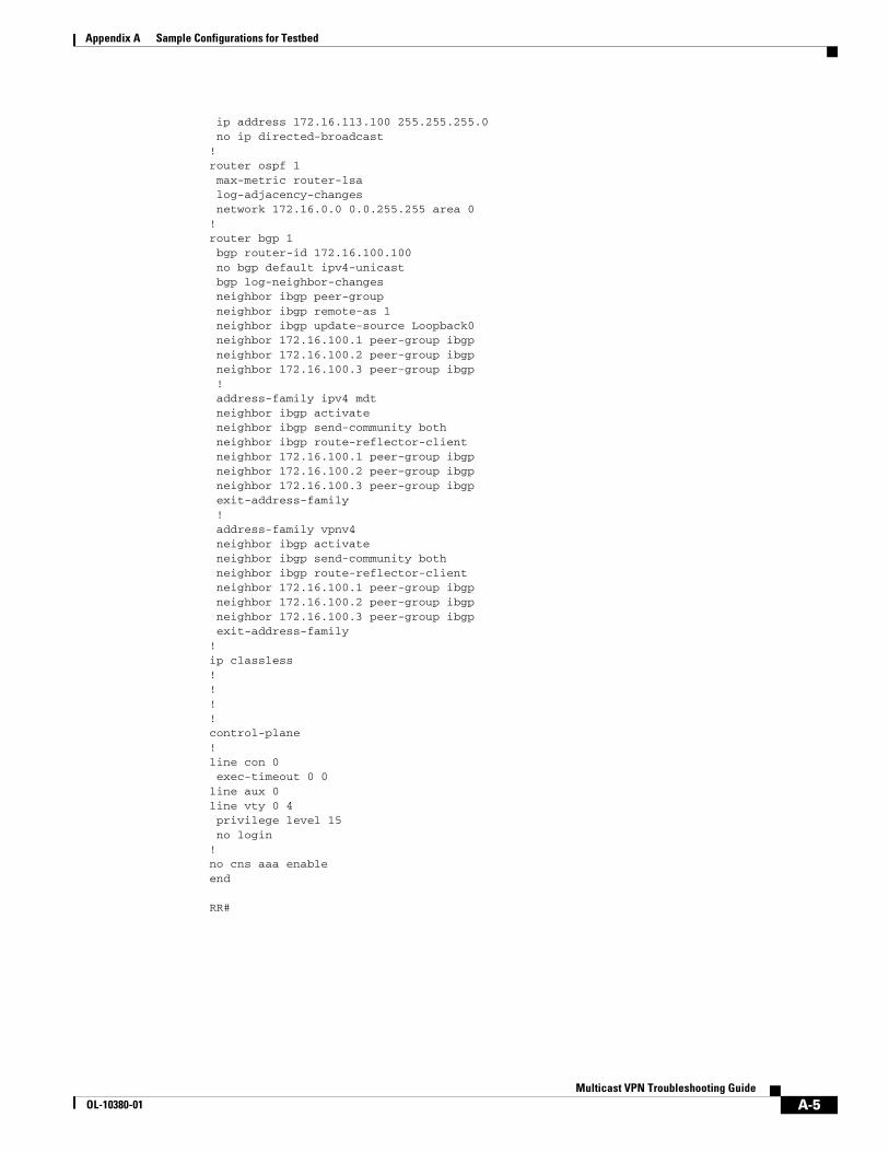
Appendix A Sample Configurations for Testbed
ip address 172.16.113.100 255.255.255.0 no ip directed-broadcast!router ospf 1 max-metric router-lsa log-adjacency-changes network 172.16.0.0 0.0.255.255 area 0!router bgp 1 bgp router-id 172.16.100.100 no bgp default ipv4-unicast bgp log-neighbor-changes neighbor ibgp peer-group neighbor ibgp remote-as 1 neighbor ibgp update-source Loopback0 neighbor 172.16.100.1 peer-group ibgp neighbor 172.16.100.2 peer-group ibgp neighbor 172.16.100.3 peer-group ibgp ! address-family ipv4 mdt neighbor ibgp activate neighbor ibgp send-community both neighbor ibgp route-reflector-client neighbor 172.16.100.1 peer-group ibgp neighbor 172.16.100.2 peer-group ibgp neighbor 172.16.100.3 peer-group ibgp exit-address-family ! address-family vpnv4 neighbor ibgp activate neighbor ibgp send-community both neighbor ibgp route-reflector-client neighbor 172.16.100.1 peer-group ibgp neighbor 172.16.100.2 peer-group ibgp neighbor 172.16.100.3 peer-group ibgp exit-address-family!ip classless! !!!control-plane!line con 0 exec-timeout 0 0line aux 0line vty 0 4 privilege level 15 no login!no cns aaa enableend
RR#
A-5Multicast VPN Troubleshooting Guide
OL-10380-01

Appendix A Sample Configurations for Testbed
CE1#sh runBuilding configuration...
Current configuration : 1011 bytes!version 12.0service timestamps debug datetime msecservice timestamps log datetime msecno service password-encryption!hostname CE1!boot-start-markerboot-end-marker!!clock timezone PST -8ip subnet-zeroip cefno ip domain-lookupip multicast-routing !!!interface Loopback0 ip address 192.168.100.1 255.255.255.255 no ip directed-broadcast!interface Ethernet0/0 ip address 192.168.1.2 255.255.255.0 no ip directed-broadcast ip pim sparse-mode!interface Serial1/0 ip address 192.168.11.2 255.255.255.0 no ip directed-broadcast ip pim sparse-mode no fair-queue!router bgp 65000 no synchronization bgp log-neighbor-changes redistribute connected neighbor 192.168.11.1 remote-as 1 no auto-summary!ip classless!ip pim autorp listener!!!control-plane!line con 0 exec-timeout 0 0line aux 0line vty 0 4 login!no cns aaa enableend
CE1#
A-6Multicast VPN Troubleshooting Guide
OL-10380-01
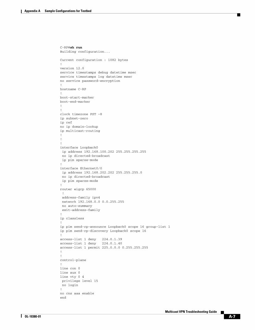
Appendix A Sample Configurations for Testbed
C-RP#sh runBuilding configuration...
Current configuration : 1082 bytes!version 12.0service timestamps debug datetime msecservice timestamps log datetime msecno service password-encryption!hostname C-RP!boot-start-markerboot-end-marker!!clock timezone PST -8ip subnet-zeroip cefno ip domain-lookupip multicast-routing !!!interface Loopback0 ip address 192.168.100.202 255.255.255.255 no ip directed-broadcast ip pim sparse-mode!interface Ethernet0/0 ip address 192.168.202.202 255.255.255.0 no ip directed-broadcast ip pim sparse-mode!router eigrp 65000 ! address-family ipv4 network 192.168.0.0 0.0.255.255 no auto-summary exit-address-family!ip classless!ip pim send-rp-announce Loopback0 scope 16 group-list 1ip pim send-rp-discovery Loopback0 scope 16!access-list 1 deny 224.0.1.39access-list 1 deny 224.0.1.40access-list 1 permit 225.0.0.0 0.255.255.255!!control-plane!line con 0line aux 0line vty 0 4 privilege level 15 no login!no cns aaa enableend
A-7Multicast VPN Troubleshooting Guide
OL-10380-01
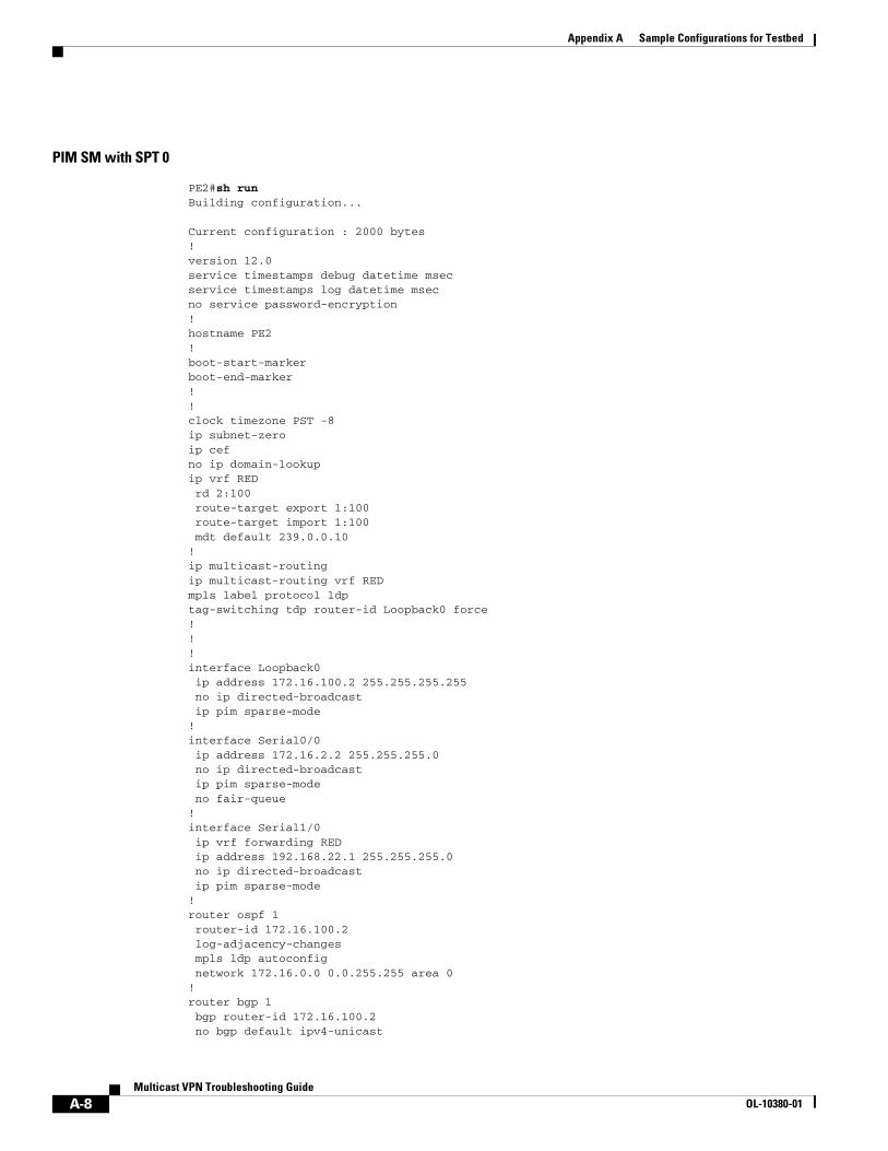
Appendix A Sample Configurations for Testbed
PIM SM with SPT 0
PE2#sh runBuilding configuration...
Current configuration : 2000 bytes!version 12.0service timestamps debug datetime msecservice timestamps log datetime msecno service password-encryption!hostname PE2!boot-start-markerboot-end-marker!!clock timezone PST -8ip subnet-zeroip cefno ip domain-lookupip vrf RED rd 2:100 route-target export 1:100 route-target import 1:100 mdt default 239.0.0.10! ip multicast-routing ip multicast-routing vrf RED mpls label protocol ldptag-switching tdp router-id Loopback0 force!!!interface Loopback0 ip address 172.16.100.2 255.255.255.255 no ip directed-broadcast ip pim sparse-mode!interface Serial0/0 ip address 172.16.2.2 255.255.255.0 no ip directed-broadcast ip pim sparse-mode no fair-queue!interface Serial1/0 ip vrf forwarding RED ip address 192.168.22.1 255.255.255.0 no ip directed-broadcast ip pim sparse-mode!router ospf 1 router-id 172.16.100.2 log-adjacency-changes mpls ldp autoconfig network 172.16.0.0 0.0.255.255 area 0!router bgp 1 bgp router-id 172.16.100.2 no bgp default ipv4-unicast
A-8Multicast VPN Troubleshooting Guide
OL-10380-01

Appendix A Sample Configurations for Testbed
bgp log-neighbor-changes neighbor 172.16.100.100 remote-as 1 neighbor 172.16.100.100 update-source Loopback0 ! address-family ipv4 neighbor 172.16.100.100 activate no auto-summary no synchronization exit-address-family ! address-family ipv4 mdt neighbor 172.16.100.100 activate neighbor 172.16.100.100 send-community both exit-address-family ! address-family vpnv4 neighbor 172.16.100.100 activate neighbor 172.16.100.100 send-community both exit-address-family ! address-family ipv4 vrf RED neighbor 192.168.22.2 remote-as 65000 neighbor 192.168.22.2 activate neighbor 192.168.22.2 as-override no auto-summary no synchronization exit-address-family!ip classless!ip pim rp-address 172.16.100.200 1ip pim ssm defaultip pim vrf RED autorp listenerip pim vrf RED spt-threshold 0! access-list 1 permit 239.0.0.0 0.0.0.255!!control-plane!!line con 0 exec-timeout 0 0line aux 0line vty 0 4 login!no cns aaa enableend
PE2#
P-RP#sh runBuilding configuration...
Current configuration : 1046 bytes
A-9Multicast VPN Troubleshooting Guide
OL-10380-01

Appendix A Sample Configurations for Testbed
!version 12.0service timestamps debug datetime msecservice timestamps log datetime msecno service password-encryption!hostname P-RP!boot-start-markerboot-end-marker!!clock timezone PST -8ip subnet-zeroip cefno ip domain-lookupip multicast-routing mpls label protocol ldptag-switching tdp router-id Loopback0 force!!! interface Loopback0 ip address 172.16.100.200 255.255.255.255 no ip directed-broadcast ip pim sparse-mode!interface Serial0/0 ip address 172.16.212.200 255.255.255.0 no ip directed-broadcast ip pim sparse-mode no fair-queue!interface Serial1/0 ip address 172.16.213.200 255.255.255.0 no ip directed-broadcast ip pim sparse-mode!router ospf 1 router-id 172.16.100.200 log-adjacency-changes mpls ldp autoconfig network 172.16.0.0 0.0.255.255 area 0!ip classless!ip pim rp-address 172.16.100.200 1ip pim ssm default!access-list 1 permit 239.0.0.0 0.0.0.255!!control-plane!!line con 0 exec-timeout 0 0line aux 0line vty 0 4 login!no cns aaa enableend
A-10Multicast VPN Troubleshooting Guide
OL-10380-01

Appendix A Sample Configurations for Testbed
A-11Multicast VPN Troubleshooting Guide
OL-10380-01

Appendix A Sample Configurations for Testbed
A-12Multicast VPN Troubleshooting Guide
OL-10380-01

OL-10380-01
A P P E N D I X B
Related Documents• Basic Multicast Troubleshooting Tools
http://www.cisco.com/warp/public/105/57.html
• IP Multicast Troubleshooting Guide
http://www.cisco.com/en/US/tech/tk828/technologies_tech_note09186a0080094b55.shtml
• IP Multicast MRM tool
http://www.cisco.com/univercd/cc/td/doc/product/software/ios122/122cgcr/fipr_c/ipcpt3/1cftools.htm
• Configuring and troubleshooting Bidir
http://www.cisco.com/en/US/products/sw/iosswrel/ps1835/products_configuration_guide_chapter09186a00800ca796.html
• mVPN MIB http://www.cisco.com/en/US/partner/products/sw/iosswrel/ps1829/products_feature_guide09186a008028e3ee.html#wp1046445
• mVPN Design Guide
http://www.cisco.com/en/US/partner/tech/tk828/tech_digest09186a00801a64a3.html
B-IMulticast VPN Troubleshooting Guide

Appendix B Related Documents
B-IIMulticast VPN Troubleshooting Guide
OL-10380-01

OL-10380-01
A P P E N D I X C
Terms and AcronymsThe following table lists and defines the key terms used in the guide.
Acronyms Definition
BGP SAFI BGP Sub-sequent Address Family
BIDIR Bidirectional PIM
BSR Bootstrap Router
C-GPA Designates a customer multicast group address, in the context of a specific VPN that is being troubleshooted.
C-RP Customer Rendez-vous Point
C-SRC Customer Source
DI Device Instrumentation
GPA Designates the default MDT multicast group address for the mVPN that is being troubleshooted
MDT Multicast Distribution Tree (MDT) group address
MTI Multicast Tunnel Interface
NH Next hop
SSM Source Specific Multicast
MRIB Multicast Routing Information Base
PEC-RCVR PE connected to the site where there is a receiver for the customer multicast traffic of a considered customer multicast source
PEC-SRC PE connected to the site where there is a Customer multicast source for the considered customer Multicast group
PEC-RP PE connected to the site where there is the Customer RP for the considered customer Multicast group
P-RP Provider Rendez-vous Point
SP Service provider
VRF VPN routing/forwarding (VRF) instance
VPN Virtual Private Network
C-1Multicast VPN Troubleshooting Guide

Appendix C Terms and Acronyms
C-2Multicast VPN Troubleshooting Guide
OL-10380-01