16: ip extensions – vpn, mobile ip, ip multicast
DESCRIPTION
16: IP Extensions – VPN, Mobile IP, IP Multicast. Last Modified: 10/23/2014 6:19:03 PM Adapted from Gordon Chaffee’s slides http://bmrc.berkeley.edu/people/chaffee/advnet98/. Virtual Private Networks (VPN). Virtual Private Networks. Definition - PowerPoint PPT PresentationTRANSCRIPT
4: Network Layer 4a-1
16: IP Extensions – VPN, Mobile IP, IP Multicast
Last Modified: 04/20/23 06:34 PM
Adapted from Gordon Chaffee’s slideshttp://bmrc.berkeley.edu/people/chaffee/advnet98/
4: Network Layer 4a-2
Virtual Private Networks (VPN)
4: Network Layer 4a-3
Virtual Private Networks
Definition A VPN is a private network constructed
within the public Internet Goals
Connect private networks using shared public infrastructure
Examples Connect two sites of a business Allow people working at home to have full
access to company network
4: Network Layer 4a-4
How accomplished?
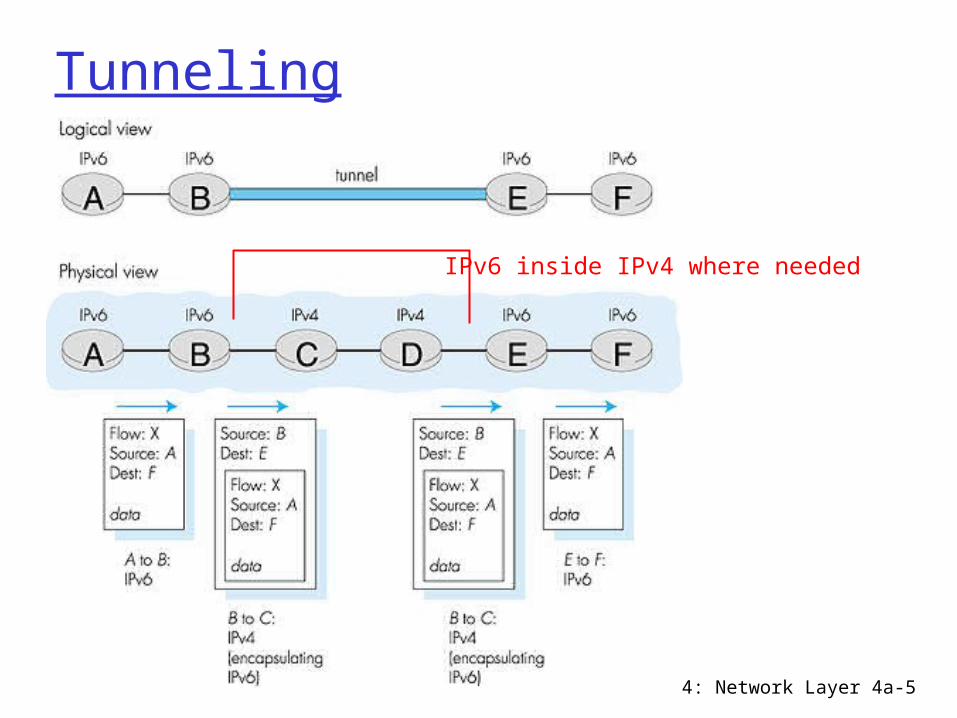
IP encapsulation and tunneling Router at one end of tunnel places
private IP packets into the data field of new IP packets (could be encrypted first for security) which are unicast to the other end of the tunnel
4: Network Layer 4a-5
Tunneling
IPv6 inside IPv4 where needed
4: Network Layer 4a-6
Motivations
Economic Using shared infrastructure lowers cost of networking Less of a need for leased line connections
Communications privacy Communications can be encrypted if required Ensure that third parties cannot use virtual network
Virtualized equipment locations Hosts on same network do not need to be co-located Make one logical network out of separate physical
networks
Support for private network features Multicast, protocols like IPX or Appletalk, etc
4: Network Layer 4a-7
Examples
Logical Network Creation Virtual Dial-Up
4: Network Layer 4a-8
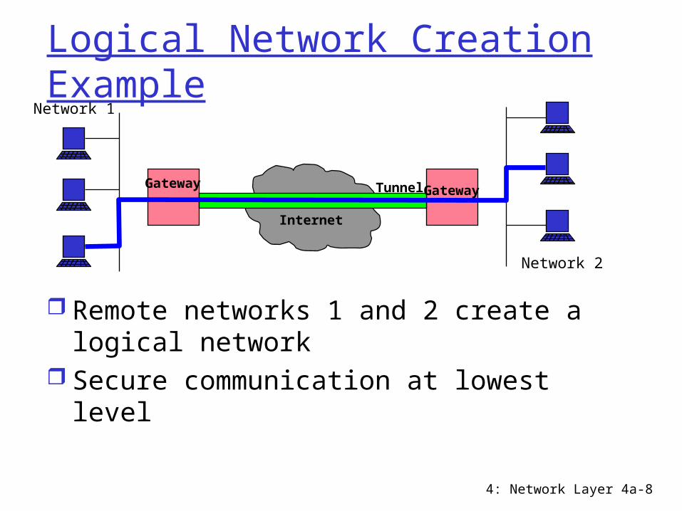
Logical Network Creation Example
Remote networks 1 and 2 create a logical network
Secure communication at lowest level
Internet
TunnelGatewayGateway
Network 1
Network 2
4: Network Layer 4a-9
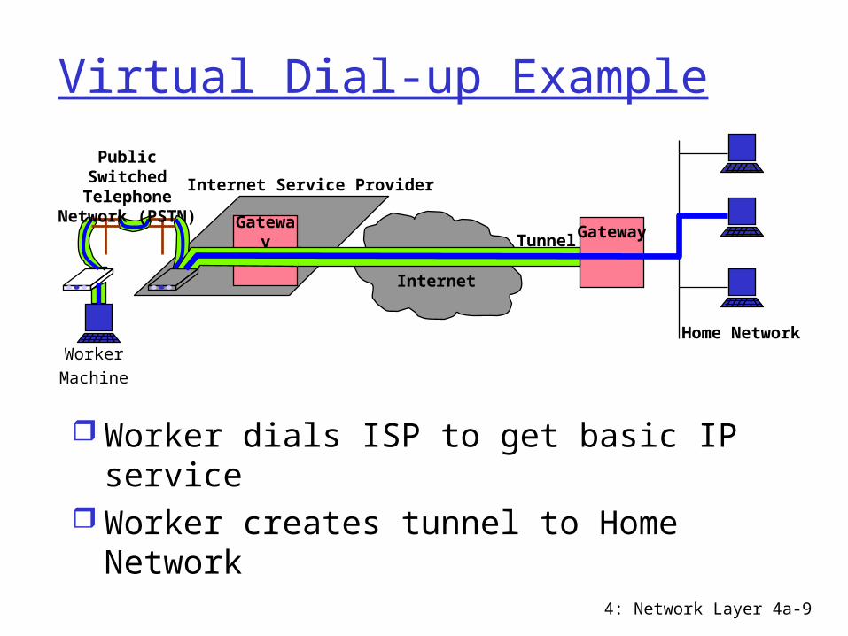
Virtual Dial-up Example
Worker dials ISP to get basic IP service Worker creates tunnel to Home Network
Internet
TunnelGateway Gateway
Internet Service ProviderPublic Switched
Telephone Network (PSTN)
Worker
Machine
Home Network
4: Network Layer 4a-10
MobileIP
4: Network Layer 4a-11
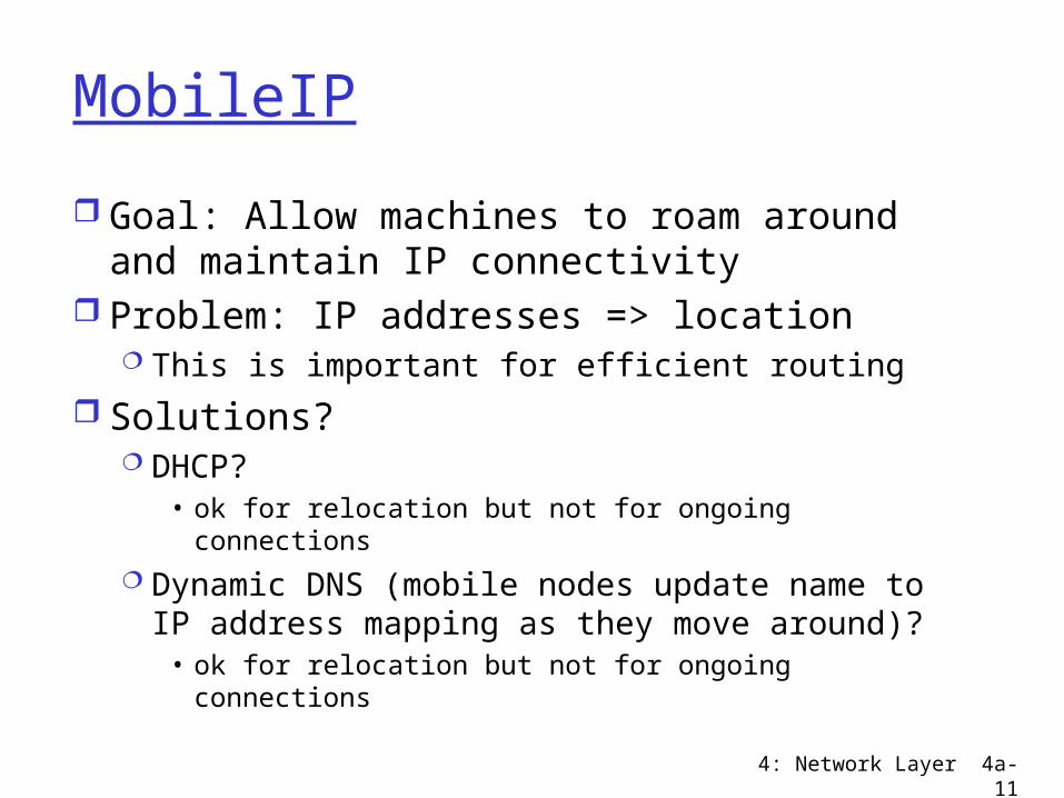
MobileIP
Goal: Allow machines to roam around and maintain IP connectivity
Problem: IP addresses => location This is important for efficient routing
Solutions? DHCP?
• ok for relocation but not for ongoing connections Dynamic DNS (mobile nodes update name
to IP address mapping as they move around)?
• ok for relocation but not for ongoing connections
4: Network Layer 4a-12
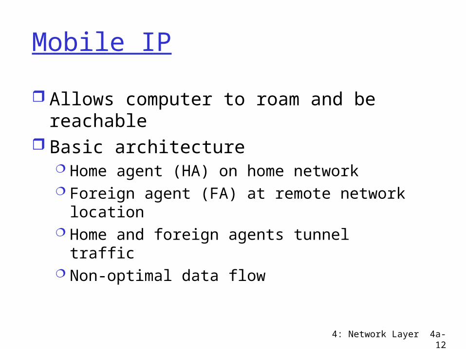
Mobile IP
Allows computer to roam and be reachable
Basic architecture Home agent (HA) on home network Foreign agent (FA) at remote network
location Home and foreign agents tunnel traffic Non-optimal data flow
4: Network Layer 4a-13
MobileIP
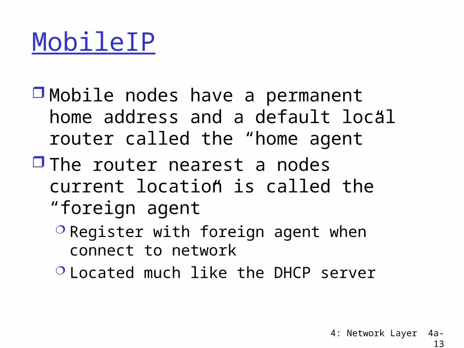
Mobile nodes have a permanent home address and a default local router called the “home agent”
The router nearest a nodes current location is called the “foreign agent” Register with foreign agent when connect to
network Located much like the DHCP server
4: Network Layer 4a-14
Forwarding Packets
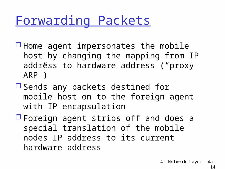
Home agent impersonates the mobile host by changing the mapping from IP address to hardware address (“proxy ARP”)
Sends any packets destined for mobile host on to the foreign agent with IP encapsulation
Foreign agent strips off and does a special translation of the mobile nodes IP address to its current hardware address
4: Network Layer 4a-15
Mobile IP Example
HomeAgent
ForeignAgent
Internet
Foreign Subnet
Home Subnet
Mobile Node
169.229.2.98
169.229.2.97
18.86.0.253
128.95.4.112
Fixed Node
Register
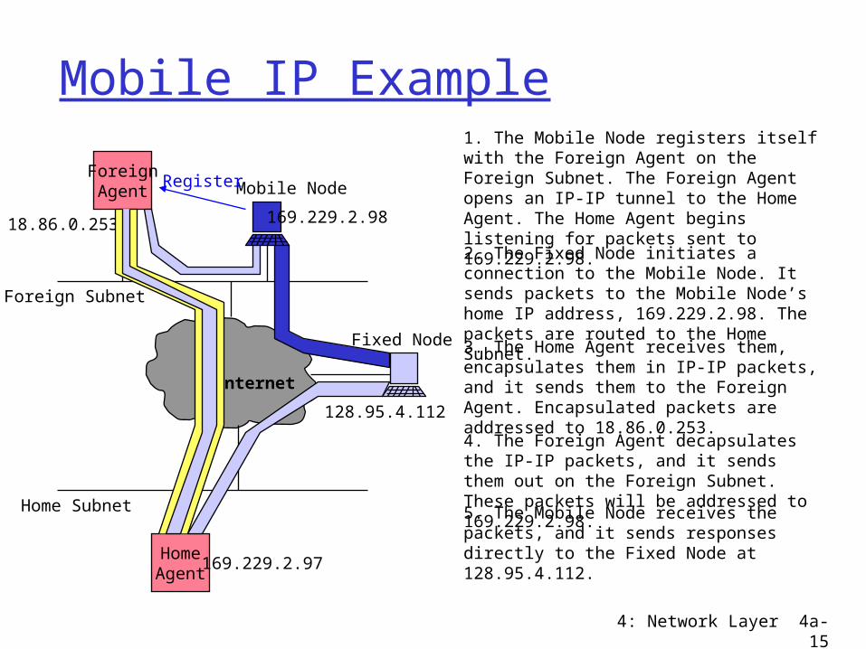
1. The Mobile Node registers itself with the Foreign Agent on the Foreign Subnet. The Foreign Agent opens an IP-IP tunnel to the Home Agent. The Home Agent begins listening for packets sent to 169.229.2.98.
2. The Fixed Node initiates a connection to the Mobile Node. It sends packets to the Mobile Node’s home IP address, 169.229.2.98. The packets are routed to the Home Subnet.
4. The Foreign Agent decapsulates the IP-IP packets, and it sends them out on the Foreign Subnet. These packets will be addressed to 169.229.2.98.5. The Mobile Node receives the packets, and it sends responses directly to the Fixed Node at 128.95.4.112.
3. The Home Agent receives them, encapsulates them in IP-IP packets, and it sends them to the Foreign Agent. Encapsulated packets are addressed to 18.86.0.253.
4: Network Layer 4a-16
Avoiding the Foreign Agent
Mobile host can also obtain a new IP address on the remote network and inform the home agent
The home agent can then resend the packet to the new IP address
4: Network Layer 4a-17
Optimizations
What if two remote hosts are temporarily close together
If they want to send traffic to each other, why should it have to go all the way to their home agents and back again
Optimizations exist to allow the sending node to learn and cache the current location of a recipient to avoid this problem
4: Network Layer 4a-18
IP Multicast
4: Network Layer 4a-19
What is multicast?
1 to N communication Bandwidth-conserving technology that
reduces traffic by simultaneously delivering a single stream of information to multiple recipients
Examples of Multicast Network hardware efficiently supports
multicast transport• Example: Ethernet allows one packet to be
received by many hosts Many different protocols and service models
• Examples: IETF IP Multicast, ATM Multipoint
4: Network Layer 4a-20
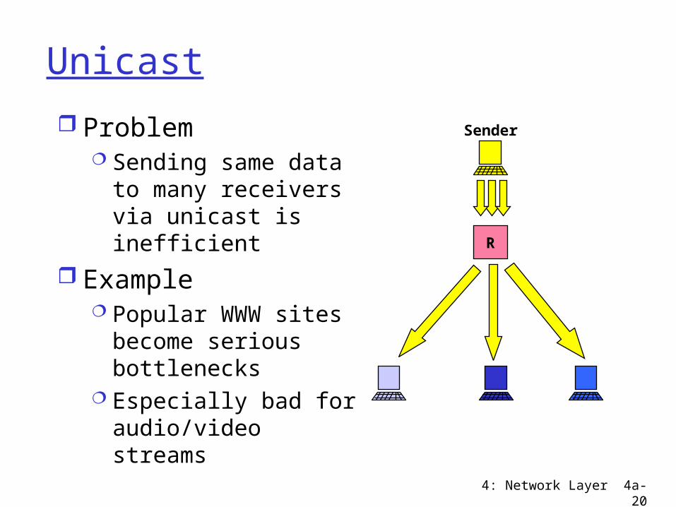
Unicast
R
Sender Problem Sending same data
to many receivers via unicast is inefficient
Example Popular WWW sites
become serious bottlenecks
Especially bad for audio/video streams
4: Network Layer 4a-21
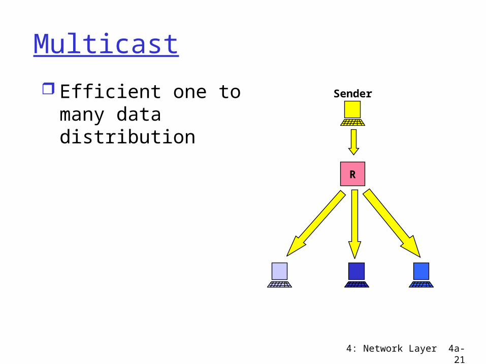
Multicast
R
Sender Efficient one to many data distribution
4: Network Layer 4a-22
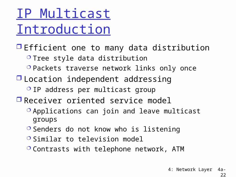
IP Multicast Introduction
Efficient one to many data distribution Tree style data distribution Packets traverse network links only once
Location independent addressing IP address per multicast group
Receiver oriented service model Applications can join and leave multicast
groups Senders do not know who is listening Similar to television model Contrasts with telephone network, ATM
4: Network Layer 4a-23
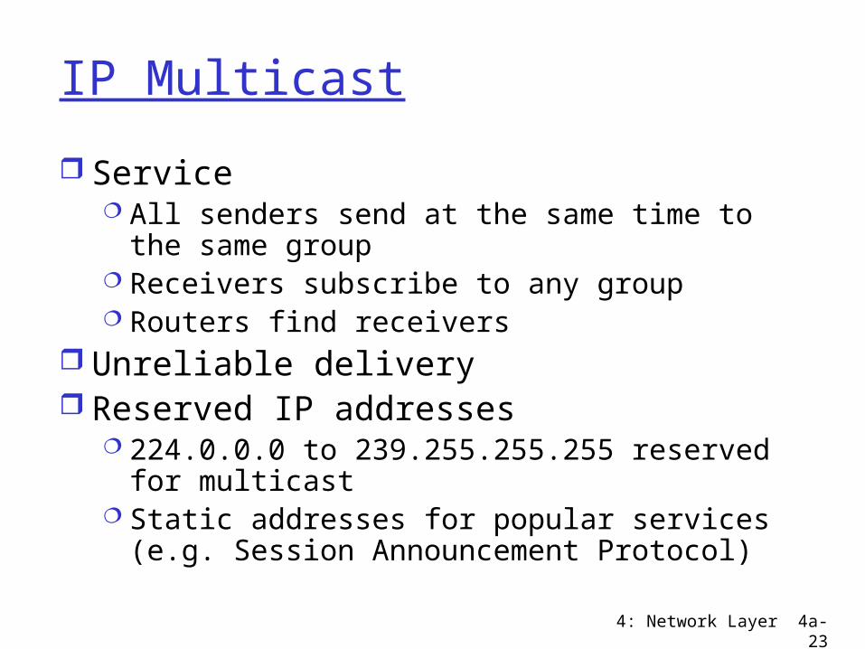
IP Multicast
Service All senders send at the same time to the
same group Receivers subscribe to any group Routers find receivers
Unreliable delivery Reserved IP addresses
224.0.0.0 to 239.255.255.255 reserved for multicast
Static addresses for popular services (e.g. Session Announcement Protocol)
4: Network Layer 4a-24
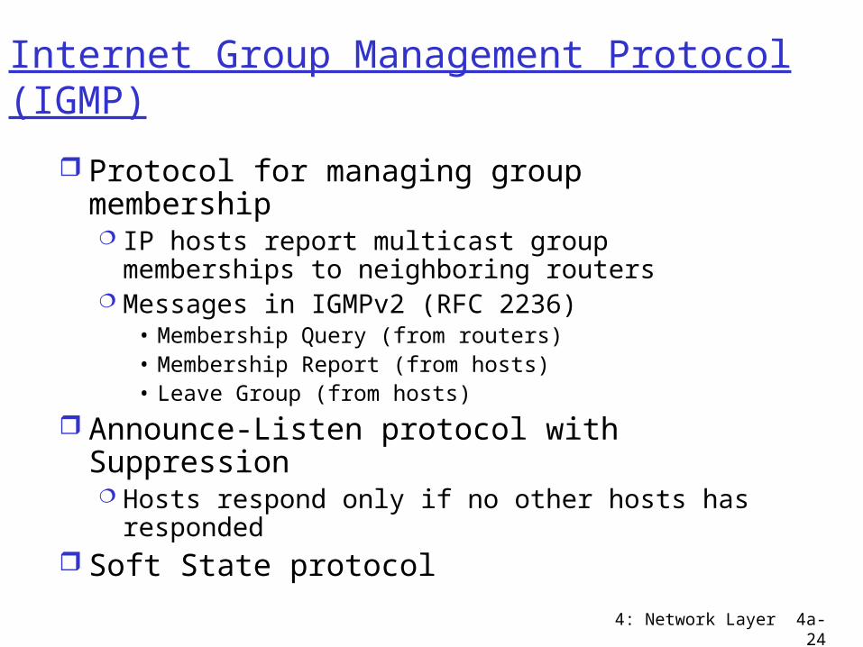
Internet Group Management Protocol (IGMP)
Protocol for managing group membership IP hosts report multicast group memberships
to neighboring routers Messages in IGMPv2 (RFC 2236)
• Membership Query (from routers)• Membership Report (from hosts)• Leave Group (from hosts)
Announce-Listen protocol with Suppression Hosts respond only if no other hosts has
responded Soft State protocol
4: Network Layer 4a-25
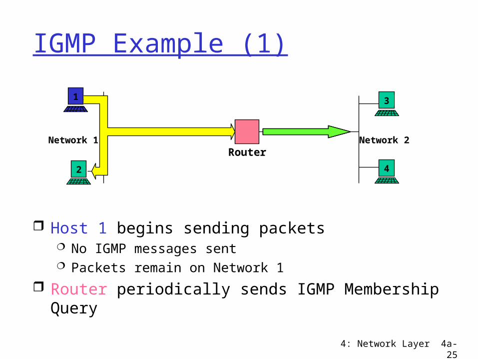
IGMP Example (1)
Network 1
Host 1 begins sending packets No IGMP messages sent Packets remain on Network 1
Router periodically sends IGMP Membership Query
Network 2Router
1
2 4
3
4: Network Layer 4a-26
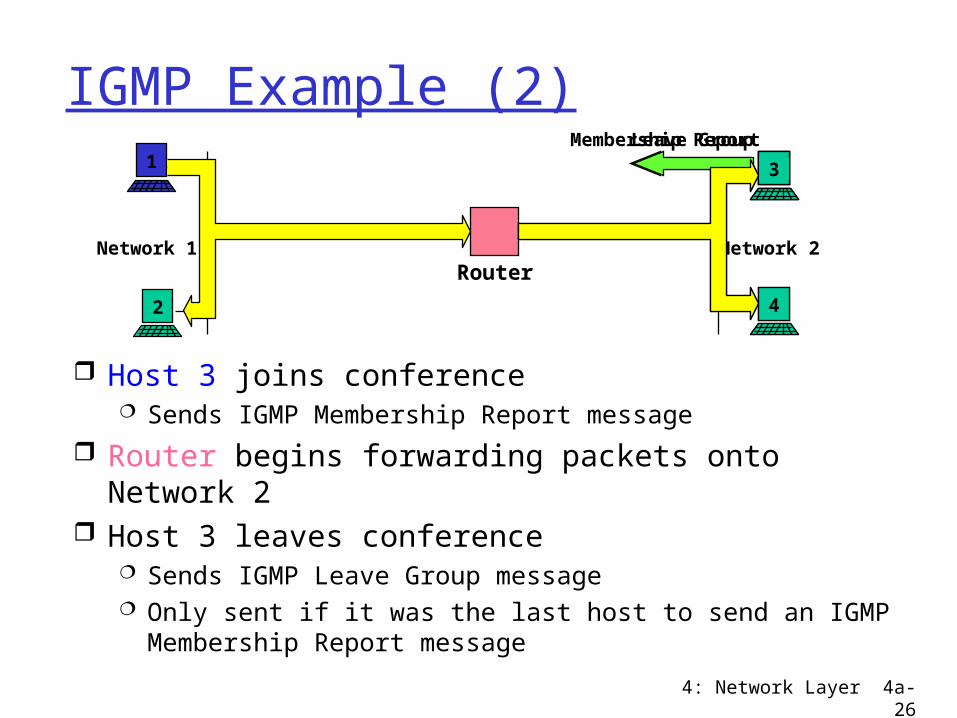
IGMP Example (2)
Network 1
Host 3 joins conference Sends IGMP Membership Report message
Router begins forwarding packets onto Network 2 Host 3 leaves conference
Sends IGMP Leave Group message Only sent if it was the last host to send an IGMP
Membership Report message
Network 2Router
1
2 4
33
Membership Report
33
Leave Group
4: Network Layer 4a-27
Source Specific Filtering: IGMPv3
Adds Source Filtering to group selection Receive packets only from specific source
addresses Receive packets from all but specific
source addresses Benefits
Helps prevent denial of service attacks Better use of bandwidth
Status: Internet Draft?
4: Network Layer 4a-28
Multicast Routing Discussion
What is the problem? Need to find all receivers in a multicast
group Need to create spanning tree of receivers
Design goals Minimize unwanted traffic Minimize router state Scalability Reliability
4: Network Layer 4a-29
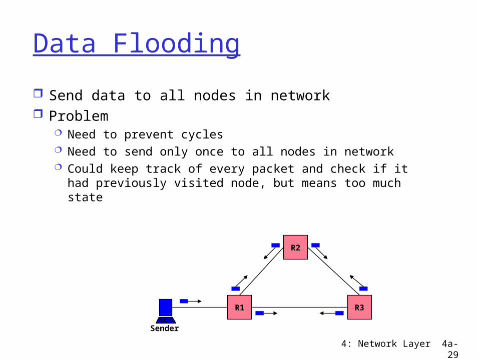
Data Flooding
Send data to all nodes in network Problem
Need to prevent cycles Need to send only once to all nodes in network Could keep track of every packet and check if it had
previously visited node, but means too much state
Sender
R3R1
R2
4: Network Layer 4a-30
Reverse Path Forwarding (RPF) Simple technique for building trees Send out all interfaces except the one
with the shortest path to the sender In unicast routing, routers send to the
destination via the shortest path In multicast routing, routers send away
from the shortest path to the sender
4: Network Layer 4a-31
Reverse Path Forwarding Example
R5 R6
R3R2
R1
R4 R7
Sender
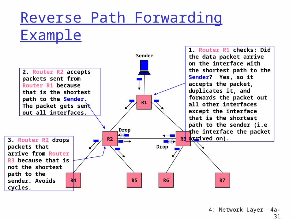
2. Router R2 accepts packets sent from Router R1 because that is the shortest path to the Sender. The packet gets sent out all interfaces.
1. Router R1 checks: Did the data packet arrive on the interface with the shortest path to the Sender? Yes, so it accepts the packet, duplicates it, and forwards the packet out all other interfaces except the interface that is the shortest path to the sender (i.e the interface the packet arrived on).
Drop
Drop3. Router R2 drops packets that arrive from Router R3 because that is not the shortest path to the sender. Avoids cycles.
4: Network Layer 4a-32
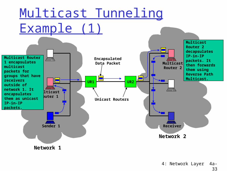
Multicast Tunneling
Problem Not all routers are multicast capable Want to connect domains with non-
multicast routers between them Solution
Encapsulate multicast packets in unicast packet
Tunnel multicast traffic across non-multicast routers
We will see more examples of tunneling later
4: Network Layer 4a-33
Multicast Tunneling Example (1)
UR1 UR2
MulticastRouter 1
MulticastRouter 2
Sender 1
EncapsulatedData Packet
Unicast Routers
Multicast Router 1 encapsulates multicast packets for groups that have receivers outside of network 1. It encapsulates them as unicast IP-in-IP packets.
Network 1
Receiver
Network 2
Multicast Router 2 decapsulates IP-in-IP packets. It then forwards them using Reverse Path Multicast.
4: Network Layer 4a-34
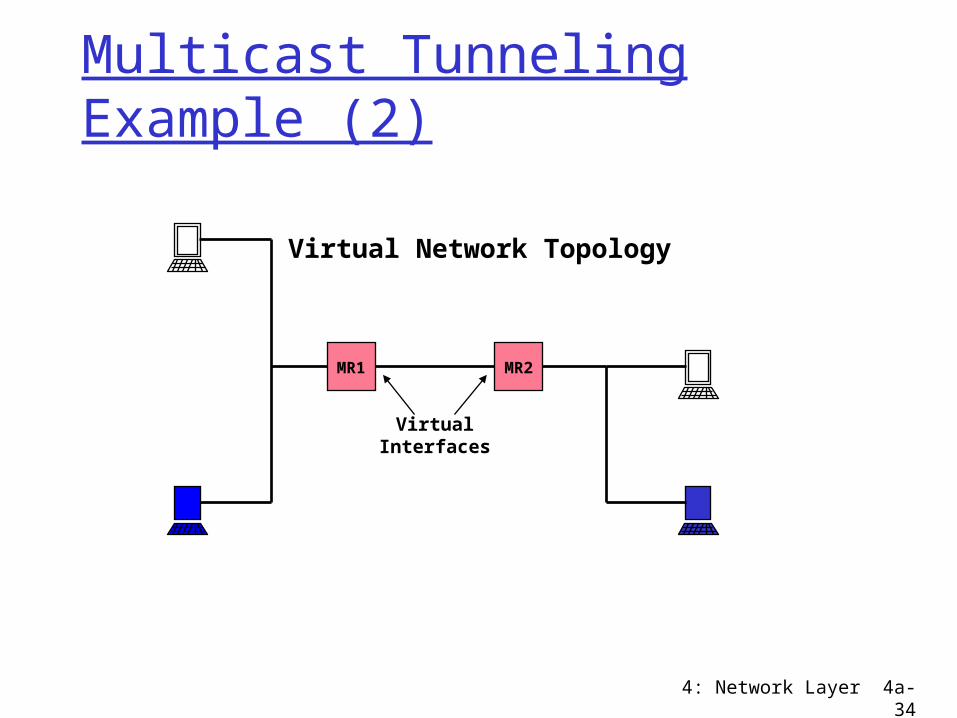
Multicast Tunneling Example (2)
MR1 MR2
VirtualInterfaces
Virtual Network Topology
4: Network Layer 4a-35
Roadmap
Finished with the network layer and IP specifics
Next on to the link layer If two hosts are on the same network
how do they send data directly to one another
4: Network Layer 4a-36
Outtakes

4: Network Layer 4a-37
Protocol Independent Multicast (PIM) Uses unicast routing table for topology Dense mode (PIM-DM)
For groups with many receivers in local/global region
Like DVMRP, a flood and prune algorithm Sparse mode (PIM-SM)
For groups with few widely distributed receivers
Builds shared tree per group, but may construct source rooted tree for efficiency
Explicit join
4: Network Layer 4a-38
MBone
MBONE Multicast capable virtual network, subset of Internet Native multicast regions connection with tunnels
In 1992, the MBone was created to further the development of IP multicast Experimental, global multicast network Served as a testbed for multicast applications
development• vat -- audio tool• vic -- video tool• wb -- shared whiteboard
4: Network Layer 4a-39
Data Distribution Choices
Source rooted trees State in routers for each sender Forms shortest path tree from each sender
to receivers Minimal delays from sources to destinations
Shared trees All senders use the same distribution tree State in routers only for wanted groups No per sender state (until IGMPv3) Greater latency for data distribution
4: Network Layer 4a-40
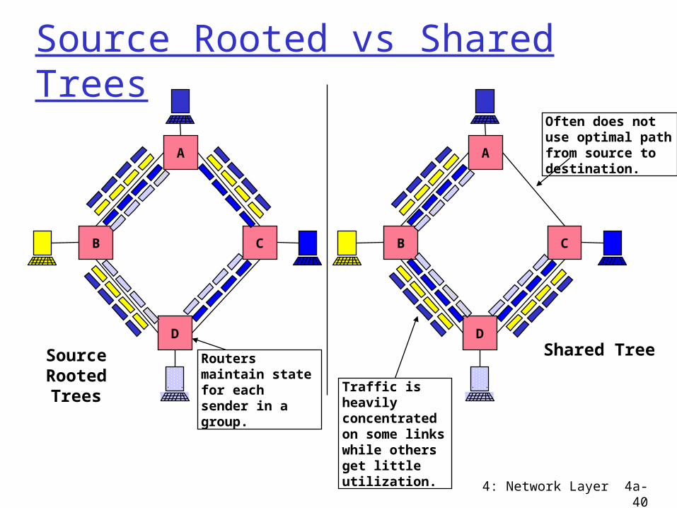
Source Rooted vs Shared Trees
B
A
C
D
B
A
C
D
Source Rooted Trees
Shared Tree
Traffic is heavily concentrated on some links while others get little utilization.
Routers maintain state for each sender in a group.
Often does not use optimal path from source to destination.
4: Network Layer 4a-41
Distance Vector Multicast Routing (DVMRP)
Steve Deering, 1988 Source rooted spanning trees
Shortest path tree Minimal hops (latency) from source to receivers
Extends basic distance vector routing Flood and prune algorithm
Initial data sent to all nodes in network(!) using Reverse Path Forwarding
Prunes remove unwanted branches State in routers for all unwanted groups Periodic flooding since prune state times out (soft
state)
4: Network Layer 4a-42
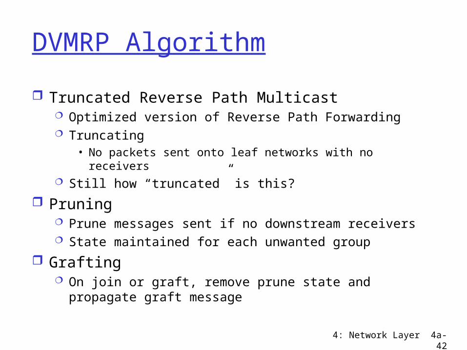
DVMRP Algorithm
Truncated Reverse Path Multicast Optimized version of Reverse Path Forwarding Truncating
• No packets sent onto leaf networks with no receivers Still how “truncated” is this?
Pruning Prune messages sent if no downstream receivers State maintained for each unwanted group
Grafting On join or graft, remove prune state and propagate
graft message

4: Network Layer 4a-43
Protocol Independent Multicast (PIM) Uses unicast routing table for topology Dense mode (PIM-DM)
For groups with many receivers in local/global region
Like DVMRP, a flood and prune algorithm Sparse mode (PIM-SM)
For groups with few widely distributed receivers
Builds shared tree per group, but may construct source rooted tree for efficiency
Explicit join
4: Network Layer 4a-44
IP Multicast in the Real World
4: Network Layer 4a-45
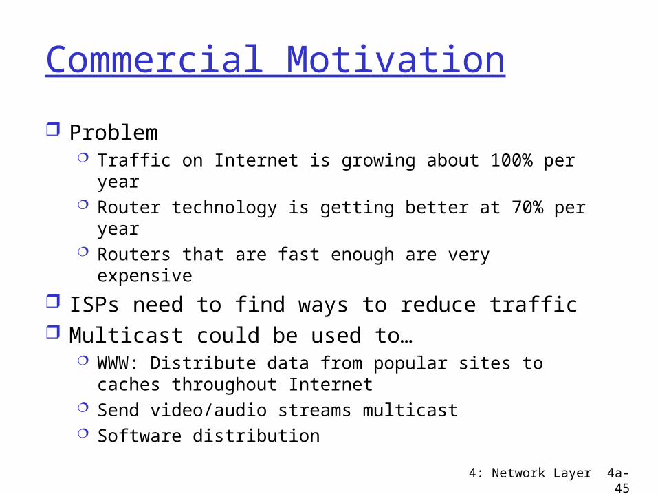
Commercial Motivation
Problem Traffic on Internet is growing about 100% per year Router technology is getting better at 70% per year Routers that are fast enough are very expensive
ISPs need to find ways to reduce traffic Multicast could be used to…
WWW: Distribute data from popular sites to caches throughout Internet
Send video/audio streams multicast Software distribution
4: Network Layer 4a-46
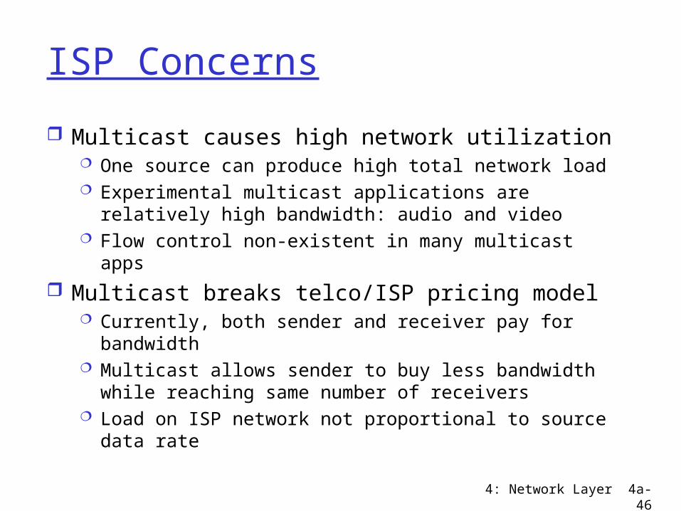
ISP Concerns
Multicast causes high network utilization One source can produce high total network load Experimental multicast applications are relatively
high bandwidth: audio and video Flow control non-existent in many multicast apps
Multicast breaks telco/ISP pricing model Currently, both sender and receiver pay for
bandwidth Multicast allows sender to buy less bandwidth while
reaching same number of receivers Load on ISP network not proportional to source data
rate
4: Network Layer 4a-47
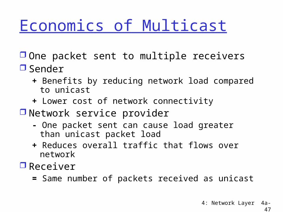
Economics of Multicast
One packet sent to multiple receivers Sender
+ Benefits by reducing network load compared to unicast
+ Lower cost of network connectivity Network service provider
- One packet sent can cause load greater than unicast packet load
+ Reduces overall traffic that flows over network
Receiver= Same number of packets received as unicast
4: Network Layer 4a-48
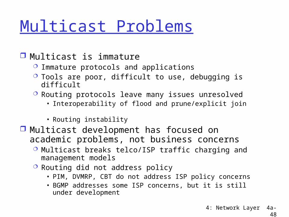
Multicast Problems
Multicast is immature Immature protocols and applications Tools are poor, difficult to use, debugging is difficult Routing protocols leave many issues unresolved
• Interoperability of flood and prune/explicit join• Routing instability
Multicast development has focused on academic problems, not business concerns Multicast breaks telco/ISP traffic charging and
management models Routing did not address policy
• PIM, DVMRP, CBT do not address ISP policy concerns• BGMP addresses some ISP concerns, but it is still under
development
4: Network Layer 4a-49
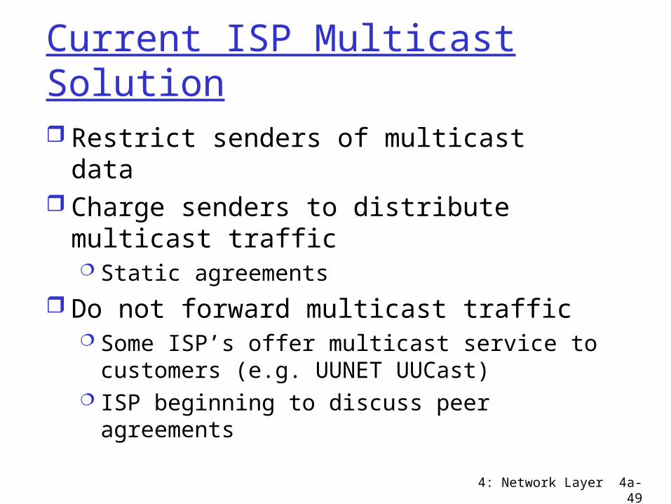
Current ISP Multicast Solution
Restrict senders of multicast data Charge senders to distribute multicast
traffic Static agreements
Do not forward multicast traffic Some ISP’s offer multicast service to
customers (e.g. UUNET UUCast) ISP beginning to discuss peer agreements

4: Network Layer 4a-50
Distance Vector Multicast Routing (DVMRP)
Steve Deering, 1988 Source rooted spanning trees
Shortest path tree Minimal hops (latency) from source to receivers
Extends basic distance vector routing Flood and prune algorithm
Initial data sent to all nodes in network(!) using Reverse Path Forwarding
Prunes remove unwanted branches State in routers for all unwanted groups Periodic flooding since prune state times out (soft
state)

4: Network Layer 4a-51
DVMRP Algorithm
Truncated Reverse Path Multicast Optimized version of Reverse Path Forwarding Truncating
• No packets sent onto leaf networks with no receivers Still how “truncated” is this?
Pruning Prune messages sent if no downstream receivers State maintained for each unwanted group
Grafting On join or graft, remove prune state and propagate
graft message
4: Network Layer 4a-52
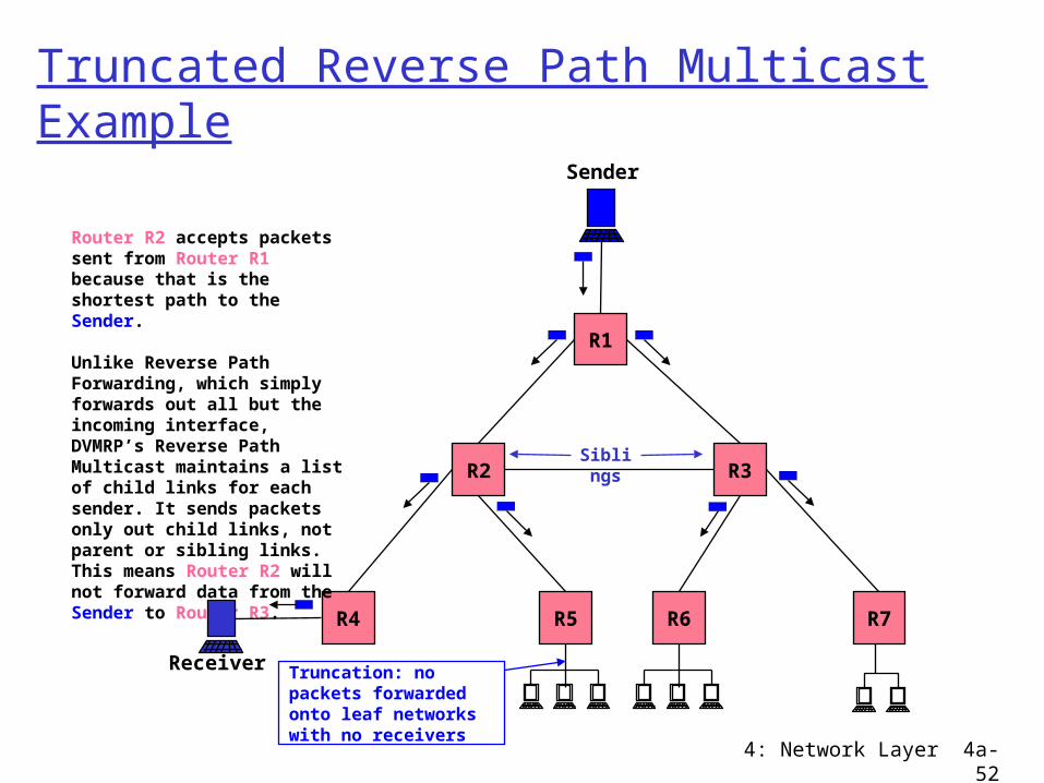
Truncated Reverse Path Multicast Example
R5 R6
R3R2
R1
R4 R7
Sender
Router R2 accepts packets sent from Router R1 because that is the shortest path to the Sender.
Unlike Reverse Path Forwarding, which simply forwards out all but the incoming interface, DVMRP’s Reverse Path Multicast maintains a list of child links for each sender. It sends packets only out child links, not parent or sibling links. This means Router R2 will not forward data from the Sender to Router R3.
Siblings
Receiver Truncation: no packets forwarded onto leaf networks with no receivers
4: Network Layer 4a-53
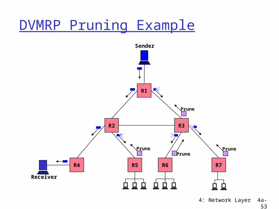
DVMRP Pruning Example
R5 R6
R3R2
R1
R4 R7
Sender
Receiver
Prune PrunePrune
Prune
4: Network Layer 4a-54
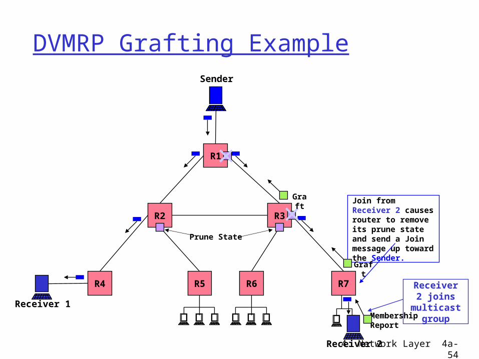
DVMRP Grafting Example
R5 R6
R3R2
R1
R4 R7
Sender
Receiver 1MembershipReport
Receiver 2
Receiver 2 joins
multicast group
Join from Receiver 2 causes router to remove its prune state and send a Join message up toward the Sender.
Graft
Prune State
Graft
4: Network Layer 4a-55
DVMRP Problems
State maintained for unwanted groups Bandwidth intensive
Periodic data flooding per group• No explicit joins, and prune state times out
Not suitable for heterogeneous networks Poorly handles large number of senders
Scaling = O(Senders, Groups) Problems of distance vector routing
slow convergence cycles due to lack of global knowledge
4: Network Layer 4a-56
Core Based Trees (CBT)
Attributes Single shared tree per group => sparse
trees Large number of senders Routing tables scale well, size = O(Groups) Bi-directional tree
4: Network Layer 4a-57
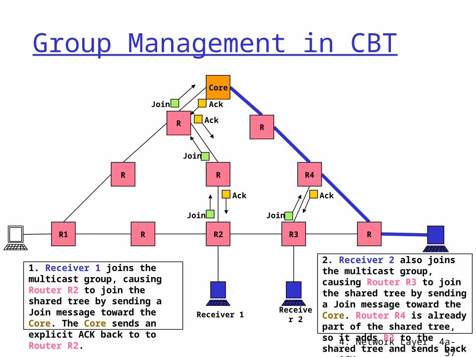
Group Management in CBT
R1 R R2 R3
RR
R
Receiver 1
Join
Join
Join
1. Receiver 1 joins the multicast group, causing Router R2 to join the shared tree by sending a Join message toward the Core. The Core sends an explicit ACK back to to Router R2.
R
R4
R
Core
Receiver 2
Ack
Ack
Ack
Join
Ack
2. Receiver 2 also joins the multicast group, causing Router R3 to join the shared tree by sending a Join message toward the Core. Router R4 is already part of the shared tree, so it adds R3 to the shared tree and sends back an ACK.
4: Network Layer 4a-58
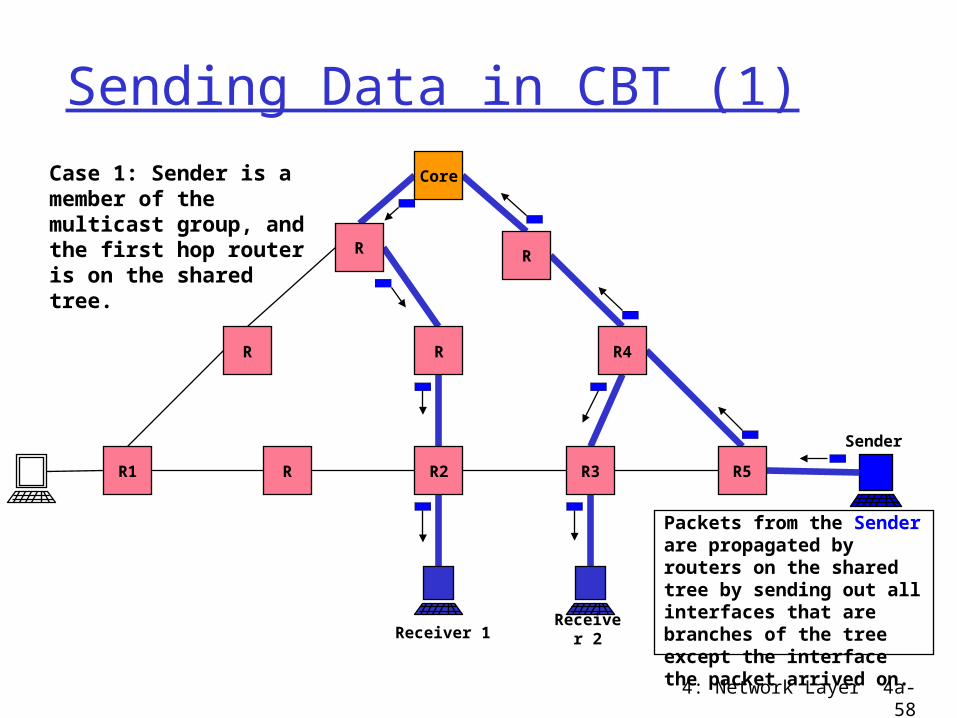
Sending Data in CBT (1)
R1 R R2 R3
RR
R
Receiver 1
Packets from the Sender are propagated by routers on the shared tree by sending out all interfaces that are branches of the tree except the interface the packet arrived on.
R5
R4
R
Core
Receiver 2
Sender
Case 1: Sender is a member of the multicast group, and the first hop router is on the shared tree.
4: Network Layer 4a-59
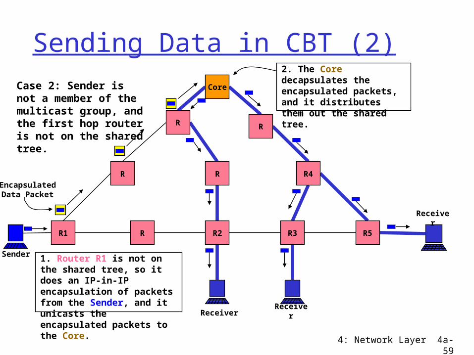
Sending Data in CBT (2)
R1 R R2 R3
RR
R
Receiver
1. Router R1 is not on the shared tree, so it does an IP-in-IP encapsulation of packets from the Sender, and it unicasts the encapsulated packets to the Core.
R5
R4
R
Core
Receiver
Receiver
Case 2: Sender is not a member of the multicast group, and the first hop router is not on the shared tree.
Sender
EncapsulatedData Packet
2. The Core decapsulates the encapsulated packets, and it distributes them out the shared tree.
4: Network Layer 4a-60
Protocol Independent Multicast (PIM) Uses unicast routing table for topology Dense mode (PIM-DM)
For groups with many receivers in local/global region
Like DVMRP, a flood and prune algorithm Sparse mode (PIM-SM)
For groups with few widely distributed receivers
Builds shared tree per group, but may construct source rooted tree for efficiency
Explicit join
4: Network Layer 4a-61
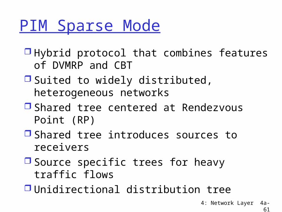
PIM Sparse Mode
Hybrid protocol that combines features of DVMRP and CBT
Suited to widely distributed, heterogeneous networks
Shared tree centered at Rendezvous Point (RP)
Shared tree introduces sources to receivers
Source specific trees for heavy traffic flows Unidirectional distribution tree
4: Network Layer 4a-62
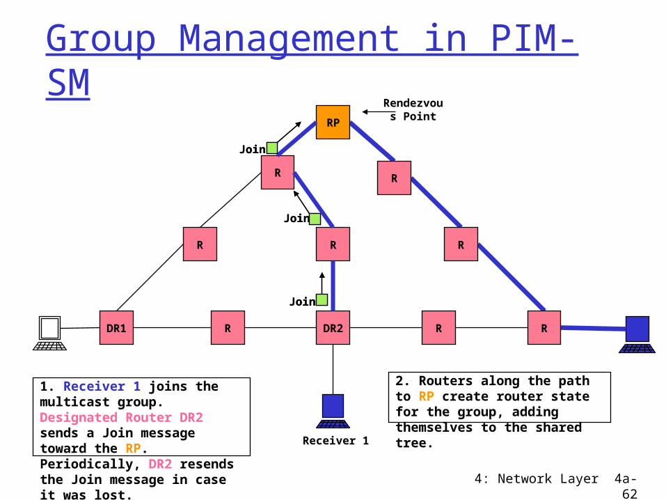
Group Management in PIM-SM
DR1 R DR2 R
RR
R
Receiver 1
Rendezvous Point
1. Receiver 1 joins the multicast group. Designated Router DR2 sends a Join message toward the RP. Periodically, DR2 resends the Join message in case it was lost.
Join
Join
Join
2. Routers along the path to RP create router state for the group, adding themselves to the shared tree.
R
R
R
RP
Join
Join
Join
4: Network Layer 4a-63
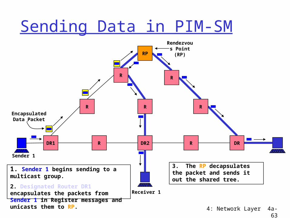
Sending Data in PIM-SM
DR1 R DR2 R
R
Receiver 1
Rendezvous Point (RP)
1. Sender 1 begins sending to a multicast group.
2. Designated Router DR1 encapsulates the packets from Sender 1 in Register messages and unicasts them to RP.
3. The RP decapsulates the packet and sends it out the shared tree.
EncapsulatedData Packet
R
R
RP
Sender 1
DR
R
R
4: Network Layer 4a-64
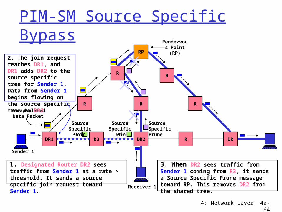
PIM-SM Source Specific Bypass
DR1 R3 DR2 R
R
Receiver 1
Rendezvous Point (RP)
1. Designated Router DR2 sees traffic from Sender 1 at a rate > threshold. It sends a source specific join request toward Sender 1.
EncapsulatedData Packet
R
R
RP
Sender 1
DR
R
R
Source Specific Join
Source Specific Join
2. The join request reaches DR1, and DR1 adds DR2 to the source specific tree for Sender 1. Data from Sender 1 begins flowing on the source specific tree to DR2.
3. When DR2 sees traffic from Sender 1 coming from R3, it sends a Source Specific Prune message toward RP. This removes DR2 from the shared tree.
SourceSpecific Prune
4: Network Layer 4a-65
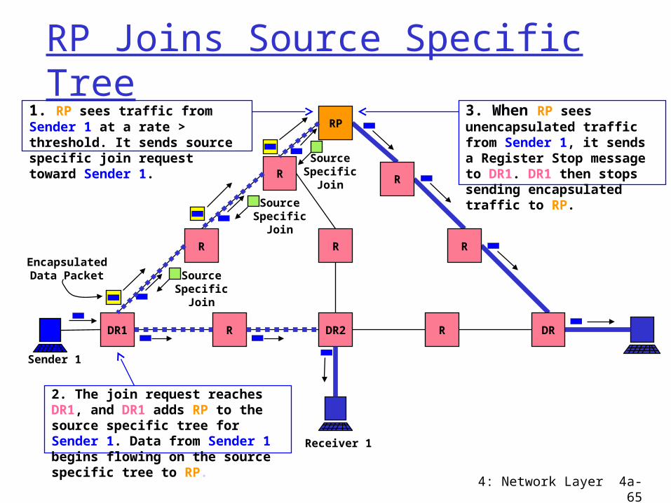
RP Joins Source Specific Tree
DR1 R DR2 R
R
Receiver 1
1. RP sees traffic from Sender 1 at a rate > threshold. It sends source specific join request toward Sender 1.
EncapsulatedData Packet
R
R
RP
Sender 1
DR
R
R
Source Specific Join
3. When RP sees unencapsulated traffic from Sender 1, it sends a Register Stop message to DR1. DR1 then stops sending encapsulated traffic to RP.
Source Specific Join
Source Specific Join
2. The join request reaches DR1, and DR1 adds RP to the source specific tree for Sender 1. Data from Sender 1 begins flowing on the source specific tree to RP.
4: Network Layer 4a-66
Problems with PIM
Global broadcasts of all Rendezvous Points
Sensitive to location of RP No administrative control over multicast
traffic; policy controls lacking Conceived as inter-domain, but now
considered intra-domain
4: Network Layer 4a-67
Classification of Tree Building Choices Flood network topology to all routers
Link state protocol Multicast Extensions to OSPF (MOSPF)
Flood and prune Distance Vector Multicast Routing Protocol
(DVMRP) Protocol Independent Multicast Dense Mode
(PIM-DM) Explicit join
Core Based Trees (CBT) Protocol Independent Multicast Sparse Mode
(PIM-SM)
4: Network Layer 4a-68
Border Gateway Multicast Protocol (BGMP)
Administrative control of multicast traffic
Hierarchical multicast address allocation Uses BGP for routing tables No global broadcasts of anything Bi-directional shared multicast routing
tree