multi-users workstations michael ling chee slang …
TRANSCRIPT
PERPUSTAKAAN UMP
1111111111111111111111111111111111111111111111 0000103096
MULTI-USERS WORKSTATIONS
MICHAEL LING CHEE SlANG
REPORT SUBMITTED IN FULFILMENT OF THE DEGREE OF COMPUTER SCIENCE (COMPUTER SYSTEM AND NETWORKING)
FACULTY OF COMPUTER SYSTEMS & SOFTWARE ENGINEERING, UNIVERSITY MALAYSIA PAHANG
2015
ABSTRACT
The Multi-Users Workstations is special designed for the industry with purpose to
minimum the use of the computer on a work place. It also used to improve the computer
functionality from a single user to multi-users on one computer on the same time. In
order to design a Multi-users workstations for Sati Wealth Consultancy Sdn. Bhd, Rapid
Application Development (RAD) has been chosen. RAD has several characteristics that
are suitable for the development of Multi-users Workstations. This system is more on
configuration to make it work properly. This system was tested with functionality
testing, and user acceptance test. The results show the functionality of the system is
passed which users satisfy with the system.
ABSTRAK
Multi-user workstations adalah khas direka untuk industry dengan tujuan untuk
meminirnunkan kegunaan sesebuah computer pada tempat kerja. Sistem mi bertujuan
untuk meningkatkan fungsi-fungsi sesebuah computer daripada kegunaan bagi seorang
kepada berbilang pengguna dalam masa yang sama. Dalam usaha untuk membangunkan
Multi-users workstations untuk Sati Wealth Consultancy Sdn. Bhd, Rapid Application
Development (RAD) telah dipilih. RAD mempunyai beberapa ciri-ciri yang sesuai bagi
pembangunan Multi-users workstations. Sistem mi terlebih kepada konfigurasi untuk
berfungsi dengan lancar. Sistem ml telah diuji dengan ujian unit, ujian fungsi , dan
ujian penerimaan pengguna. Keputusan menunjukkan fungsi sistem itu diluluskan yang
pengguna berpuas hati dengan system.
7
Multi-users Workstations
Michael Ling Chee Siang DR.MOHAMED ARIFF BIN AMEEDEEN Computer Science in Networking University Malaysia Pahang
University Malaysia Pahang Pahang, Malaysia Pahang, Malaysia
[email protected] [email protected]
Abstract— The multi-user workstation is design to make human more easier to interact with the computer. This system is to make a computer can be uses by multi user on the same time. In order to develop a multi-touch workstation Rapid Application Development (BAD) has been chosen. BAD has several characteristics that are suitable for development of this multi-user workstation. That are many type of methodology can be uses in order to develop the project, such as RAD, waterfall and etc. Those methodology are the platform of implemented the project using the certain way. The methodology that has been applied could be reliable and applicable with the system and project that are developed.
I. INTRODUCTION
In this age, technology is constantly become more high technology and moden. The computer is no an exception too. The development of new technologies have realized and focused on the interaction between computer and human.
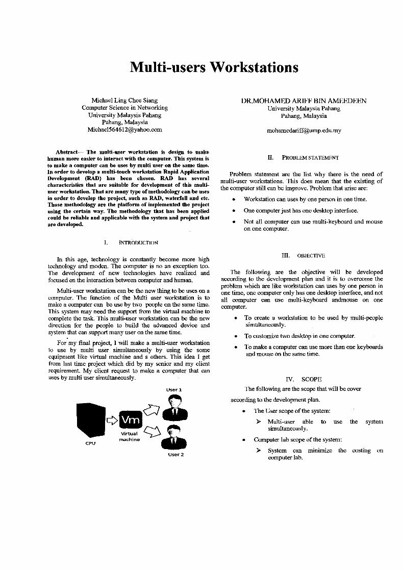
Multi-user workstation can be the new thing to be uses on a computer. The function of the Multi user workstation is to make a computer can be use by two people on the same time. This system may need the support from the virtual machine to complete the task. This multi-user workstation can be the new direction for the people to build the advanced device and system that can support many user on the same time.
For my final project, I will make a multi-user workstation to use by multi user simultaneously by using the some equipment like virtual machine and s others. This idea I get from last time project which did by my senior and my client requirement. My client request to make a computer that can uses by multi user simultaneously.
User 1
Virtual machine
CPU
User 2
II. PROBLEM STATEMENT
Problem statement are the list why there is the need of multi-user workstations. This does mean that the existing of the computer still can be improve. Problem that arise are:
• Workstation can uses by one person in one time.
• One computer just has one desktop interface.
• Not all computer can use multi-keyboard and mouse on one computer.
III. OBJECTIVE
The following are the objective will be developed according to the development plan and it is to overcome the problem which are like workstation can uses by one person in one time, one computer only has one desktop interface, and not all computer can use multi-keyboard andmouse on one computer.
• To create a workstation to be used by multi-people simultaneously.
• To customize two desktop in one computer.
• To make a computer can use more than one keyboards and mouse on the same time.
IV. SCOPE The following are the scope that will be cover
according to the development plan.
• The User scope of the system:
> Multi-user able to use the system simultaneously.
• Computer lab scope of the system:
> System can minimize the costing on computer lab.
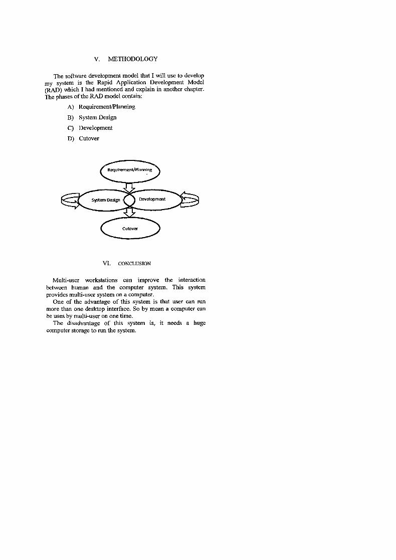
V. METHODOLOGY
The software development model that I will use to develop my system is the Rapid Application Development Model (RAD) which I had mentioned and explain in another chapter. The phases of the RAD model contain:
A) Requirement/Planning
B) System Design
C) Development
D) Cutover
Requirement/Planning
System Design Development
VI. CONCLUSION
Multi-user workstations can improve the interaction between human and the computer system. This system provides multi-user system on a computer.
One of the advantage of this system is that user can run more than one desktop interface. So by mean a computer can be uses by multi-user on one time.
The disadvantage of this system is, it needs a huge computer storage to run the system.
TABLE OF CONTENTS
TITLE PAGE
SUPERVISOR'S DECLARATION .2
STUDENT'S DECLARATION ...................................................................................... 3
ACKNOWLEDGEMENT .............................................................................................. 5
ABSTRACT ..................................................................................................................... 6
ABSTRAK .......................................................................................................................7
TABLEOF CONTENTS ............................................................................................... 8
CHAPTER! .................................................................................................................. 11
INTRODUCTION ........................................................................................................ 11
1.1 Introduction ...................................................................................................... 11
1.2 Problem Statement...........................................................................................12
1 .3 Objectives.........................................................................................................12
1.4 Scope................................................................................................................13
1.5 Thesis Organization .........................................................................................13
CHAPTER2 ................................................................................................................... 14
LITERATUREREVIEW ............................................................................................ 14
2.1 Review on Existing System .............................................................................14
2. 1.1 Window Virtual PC ..................................................................................14
2.1.2 VirtuaiBox ................................................................................................14
2.1.3 QEMU.......................................................................................................15
2.1.4 Summary of existing system.....................................................................15
2.2 Software Development Methodology..............................................................16
8
22.1 Waterfall Model Overview . 16
2.2.2 Rapid Application Development (RAD) Model .......................................18
2.2.3 Prototyping Model .............................................................................. ......21
25 2.3 Tools Used .......................................................................................................
2.3.1 Microsoft Word 2Ol3 ............................................................................ ... . 25
2.3.2 Microsoft PowerPoint 2013...................................................................... 25
2.3.3 Microsoft Project 2013 ............................................................................. 25
25 2.4 Conclusion ................................................................. .......................................
26 CHAPTER . ...................................................... ............................................................
26 METHODOLOGY .............................................. .........................................................
26 3.1 Methodology .................................................................. ..................................
27 3.2 Requirement planning .................................................. ....................................
27 3.3 Modem existing system ...................................................................................
28 3.4 Analyzing and finalize requirement ............................................................. ....
28 3.5 User Design .................................................. ....................................................
28 3.6 Hardware Requirement ................................. ...................................................
29 3.7 Software Requirement .................................................... ..................................
30 CHAPTER . ...................................................... .......................................................
30 DESIGN ........................................................ ......................................................
30 4.1 Logical Design ....................................... ..........................................................
31 4.2 Logical Flowchart ................................................... .........................................
32 CHAPTER . .................................................... ........................................................
32 IMPLEMENTATION ............................................... ...................................................
32 5.1 System Interface ................................................. ..............................................
CHAPTER6 ...............................................................................................................35
RESULT& DISCUSSION .................................................... .......................................
35 6 .1 Introduction ...................................................... ...............................................
9

6.2.. Result analysis .35
6.3 Advantage and Disadvantages .........................................................................36
CHAPTER 7.................................................................................................................. 37
CONCLUSION ............................................................................................................. 37
7.1 Conclusion........................................................................................................37
10
CHAPTER 1
INTRODUCTION
This chapter briefly discuss on the overview of the project into three parts. The first part
discusses on the problem statement discovered in real situation and findings. Next, the
project objective is determined by project's goal and aim; follow by the project scope
where the boundary limit is enclosed.
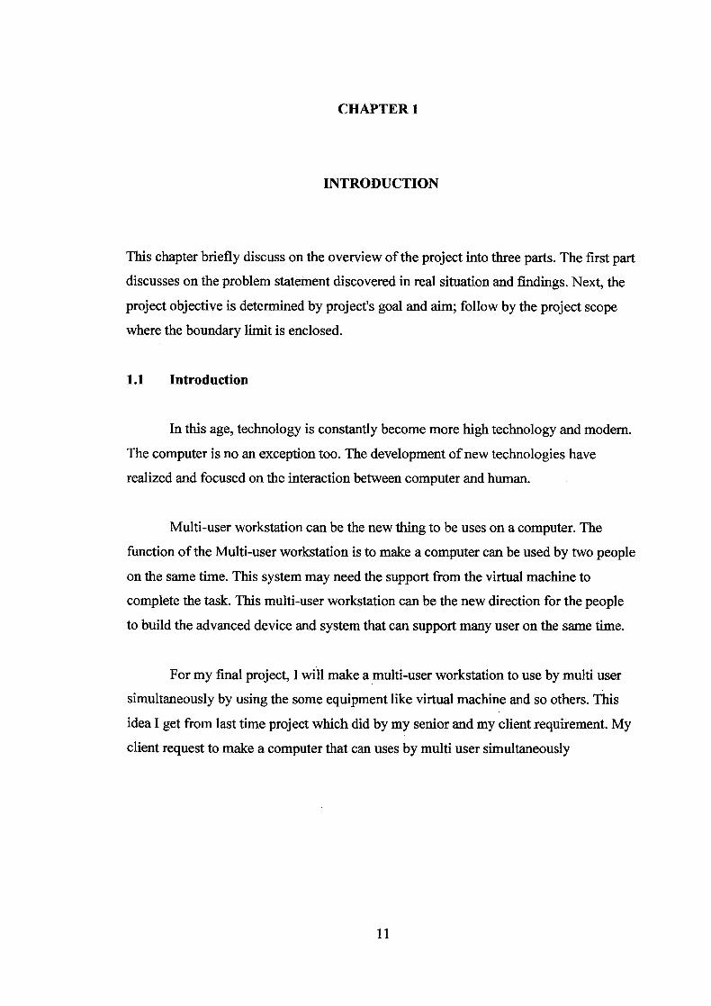
1.1 Introduction
In this age, technology is constantly become more high technology and modem.
The computer is no an exception too. The development of new technologies have
realized and focused on the interaction between computer and human.
Multi-user workstation can be the new thing to be uses on a computer. The
function of the Multi-user workstation is to make a computer can be used by two people
on the same time. This system may need the support from the virtual machine to
complete the task. This multi-user workstation can be the new direction for the people
to build the advanced device and system that can support many user on the same time.
For my final project, I will make a multi-user workstation to use by multi user
simultaneously by using the some equipment like virtual machine and so others. This
idea I get from last time project which did by my senior and my client requirement. My
client request to make a computer that can uses by multi user simultaneously
11
1.2 Problem Statement
In this age, the computer become more powerful and modern, the hardware and
the software using is more far greater from the past time. Even though, computer
become more modern or using the high specification but so far computer just can uses
by one person in one time and not all software can operate the workstation uses by
multi-users simultaneously, normally all work is depend on the hardware to make it
operate multi-user workstation.
Besides that, computer now only has one desktop and use it directly. The
computer still don't have the ability to operate two desktop to work on one screen for
multi-user uses simultaneously. Even, now already got software that can operate multi
operating system on a computer but the computer still not able to work simultaneously.
Furthermore, not all computer can use multi-keyboard and multi-mouse on one
computer. Almost all the computer just able to run one mouse and keyboard on the
same time. Without the virtual machine, the computer may have face the problem on
connecting with the multi-mouse and keyboard.
1.3 Objectives
The following are the objective will be developed according to the development
plan and it is to overcome the problem which are like workstation can uses by one
person in one time, one computer only has one desktop interface, and not all computer
can use multi-keyboard and mouse on one computer.
• To create a workstation to be used by multi-people simultaneously.
• To customize two desktop in one computer.
• To make a computer can use more than one keyboards and mouse on the same
time.
12

1.4 •.. Scope
The following are the scope that will be cover according to the development plan;
• User
Multi-users able to use the system simultaneously.
• Computer lab
This system can minimize the costing on computer lab.
1.5 Thesis Organization
This thesis is disjointed into two chapters where each chapter denotes different details in
this project. Below displays a brief summary of the content for each respective chapters.
L Chapter 1
Introduction of the project background follow with the project problem
statement, project objectives and project scopes.
ii. Chapter 2
Research and literature review relevant to the project.
iii. Chapter 3
Project analysis, design and methodology are presented.
iv. Chapter 4
Design of the diagram presented.
V. Chapter 5
Discuss on the system implementation phase.
vi. Chapter 6
The testing result of the system and discussion on the result are presented.
vii. Chapter 7
Conclusion of the thesis presented.
13

CHAPTER 2
LITERATURE REVIEW
In this part, the existing and current system, operation environment, regards to this
project is reviewed as research finding output. This chapter will also review on the
software development methodology of the project concisely.
2.1 Review on Existing System
2.1.1 Window Virtual PC
Windows XP Mode works in two ways both as a virtual operating system and as
a way to open programs within Windows 7. It runs in a separate window on the
Windows 7 desktop, much like a program, except it's a fully-functional, fully-licensed
version of Windows XP. In Windows XP Mode, you can access your physical
computer's CDIDVD drive, install programs, save files, and perform other tasks as if
you were using a computer running Windows XP
2.1.2 VirtualBox
Virtual Box was designed to he modular and flexible. The Virtual Box service
process which always runs in the background. This process is started automatically by
the first Virtual Box client process (the GUI, VBoxManage, VBoxHeadless, the web
service or others) and exits a short time after the last client exits. The service is
responsible for bookkeeping, maintaining the state of all VMs, and for providing
communication between Virtual Box components. VirtualBox consists of many more or
less separate components.
14
2.1.3 QEMU
QEMU is an open source emulator capable of running another operating system
in a window. QEMU is faster than most emulators because it uses dynamic
recompilation, meaning it translates entire pages and keeps the translated pages around
(sort of like a Java JIT compiler, or Transmeta's code morphing layer). The translation
overhead is similar to the pause fetching code from disk, or the latency of copying
DRAM into L2 cache. it occurs exactly at the places systems are already slow, and thus
the places any modem software that cares about performance is optimized to do as little
as possible.
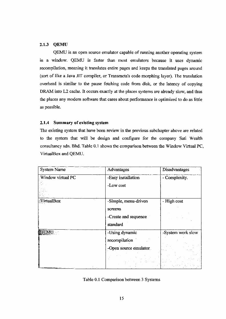
2.1.4 Summary of existing system
The existing system that have been review in the previous subchapter above are related
to the system that will be design and configure for the company Sati Wealth
consultancy sdn. Bhd. Table 0.1 shows the comparison between the Window Virtual PC,
VirtualBox and QEMU.
System Name Advantages Disadvantages
Window virtual PC -Easy installation - Complexity.
-Low cost
VirtualBox -Simple, menu-driven -. High cost
screens
-Create and sequence
standard
EMU
-Using dynamic -System work slow
recompilation
-Open source emulator .
Table 0.1 Comparison between 3 Systems
15
2.2 Software Development Methodology
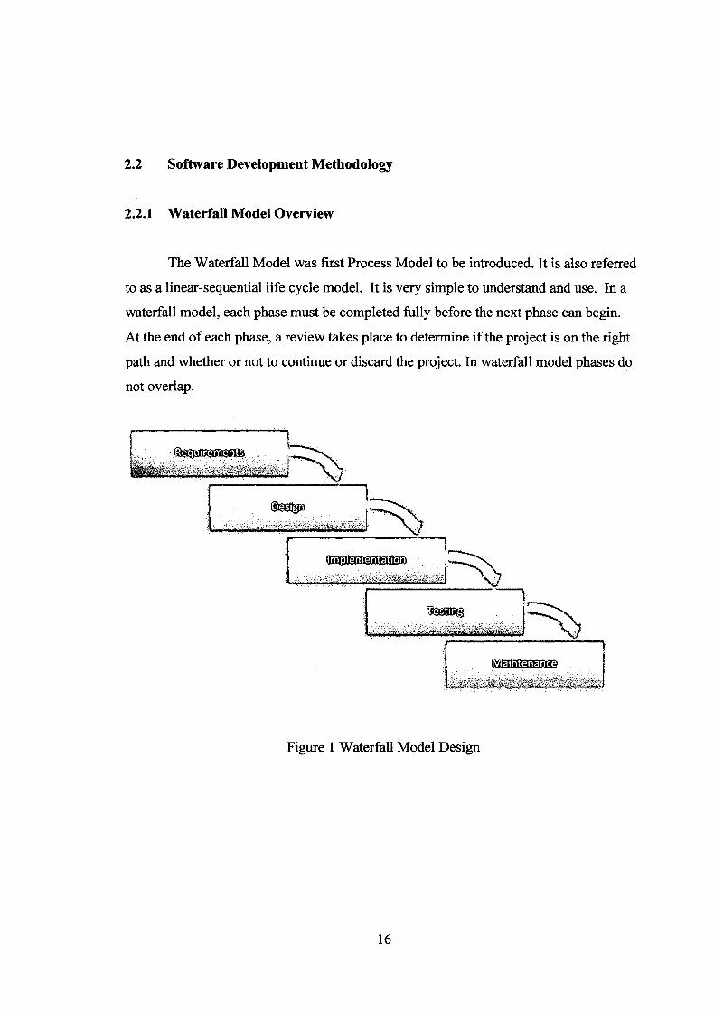
2.2.1 Waterfall Model Overview
The Waterfall Model was first Process Model to be introduced. It is also referred
to as a linear-sequential life cycle model. It is very simple to understand and use. In a
waterfall model, each phase must be completed fully before the next phase can begin.
At the end of each phase, a review takes place to determine if the project is on the right
path and whether or not to continue or discard the project. In waterfall model phases do
not overlap.
:IpnntpOfl
Figure 1 Waterfall Model Design
16
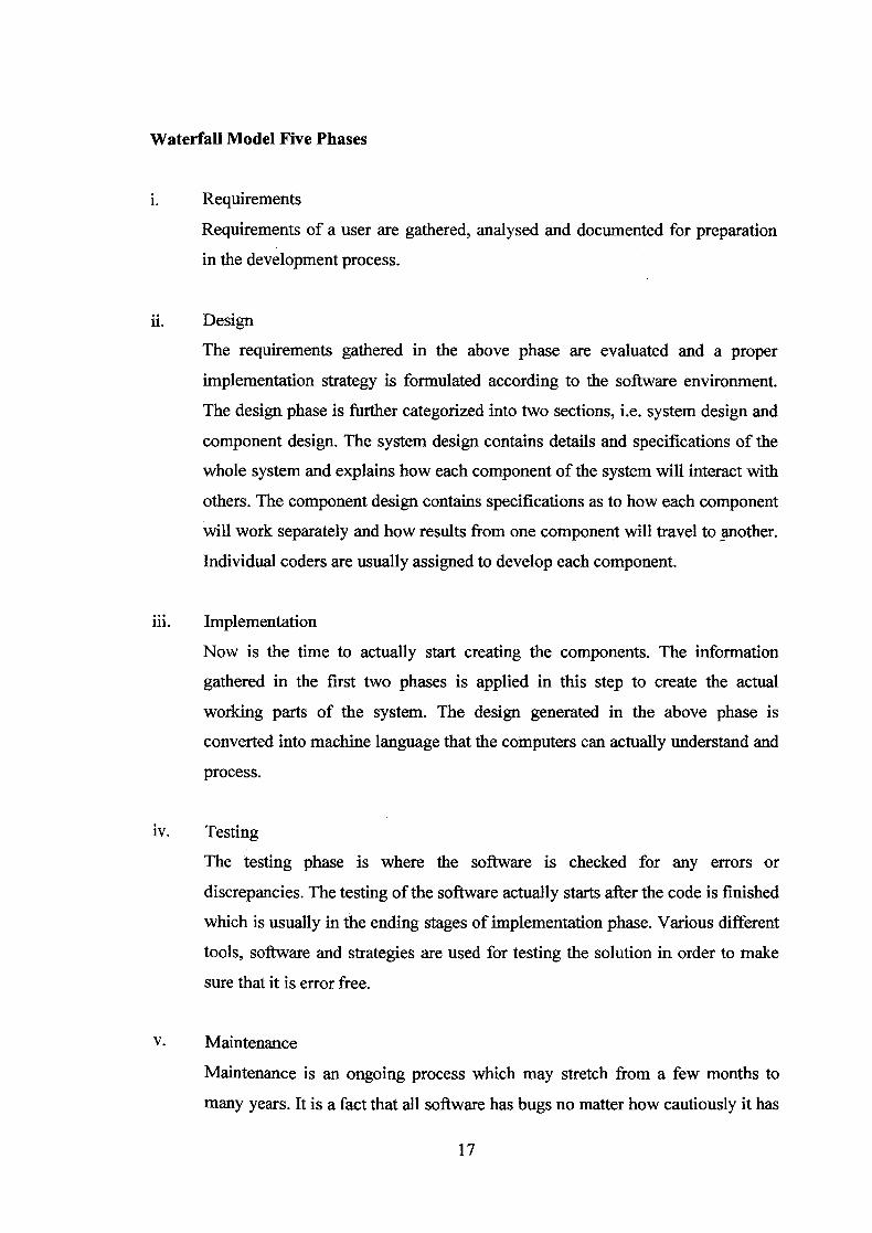
Waterfall Model Five Phases
i. Requirements
Requirements of a user are gathered, analysed and documented for preparation
in the development process.
ii. Design
The requirements gathered in the above phase are evaluated and a proper
implementation strategy is formulated according to the software environment.
The design phase is further categorized into two sections, i.e. system design and
component design. The system design contains details and specifications of the
whole system and explains how each component of the system will interact with
others. The component design contains specifications as to how each component
will work separately and how results from one component will travel to another.
Individual coders are usually assigned to develop each component.
iii. Implementation
Now is the time to actually start creating the components. The information
gathered in the first two phases is applied in this step to create the actual
working parts of the system. The design generated in the above phase is
converted into machine language that the computers can actually understand and
process.
iv. Testing
The testing phase is where the software is checked for any errors or
discrepancies. The testing of the software actually starts after the code is finished
which is usually in the ending stages of implementation phase. Various different
tools, software and strategies are used for testing the solution in order to make
sure that it is error free.
V. Maintenance
Maintenance is an ongoing process which may stretch from a few months to
many years. It is a fact that all software has bugs no matter how cautiously it has
17

been developed and tested. Furthermore, with the passage of time, requirements
will also change and modifications or additions will be required to keep it
effective. All this work comes under the umbrella term - maintenance.
Waterfall Model Pros and Cons
Table 1 Waterfall Model Pros and Cons
ITM Simple and easy to understand and use No working software is produced until late
during the life cycle.
Easy to manage due to the rigidity of the High amounts of risk and uncertainty.
model. Each phase has specific
deliverables and a review process.
Poor model for long and ongoing projects Phases are processed and completed one at
atime.
Works well for smaller projects where Not suitable for the projects where
requirements are very well understood. requirements are at a moderate to high risk
of changing. So risk and uncertainty is
high with this process model.
Clearly defined stages. It is difficult to measure progress within
stages.
Well understood milestones. Cannot accommodate changing
requirements.
2.2.2 Rapid Application Development (RAD) Model
RAD Model Overview
RAD model is Rapid Application Development model. It is a type of
incremental model. In RAD model the components or functions are developed in
Parallel as if they were mini projects. The developments are time boxed, delivered and
then assembled into a working prototype. This can quickly give the customer
18
something to see and use and to provide feedback regarding the delivery and their
requirements.
Professor Clifford Kettemborough of Whitehead College, University of
Redlands, defines Rapid Application Development as "an approach to building
computer systems which combines Computer-Assisted Software Engineering (CASE)
tools and techniques, user-driven prototyping, and stringent project delivery time limits
into a potent, tested, reliable formula for top-notch quality and productivity. RAD
drastically raises the quality of finished systems while reducing the time it takes to build
them."
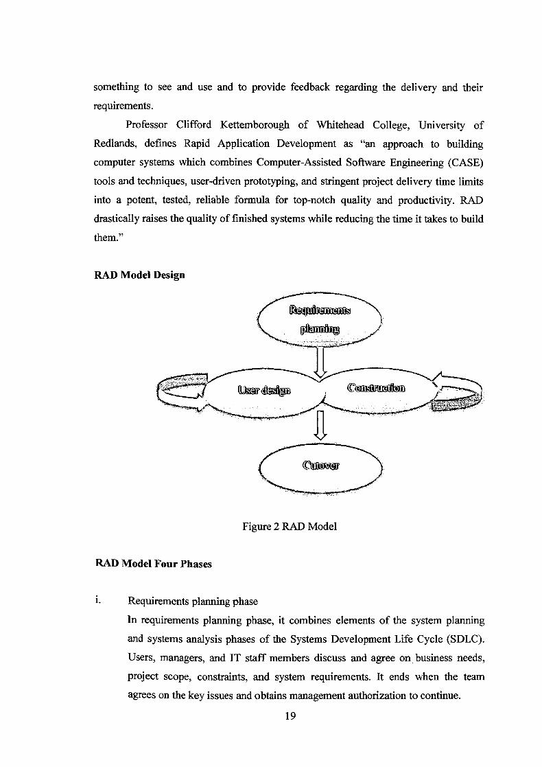
RAD Model Design
Figure 2 RAD Model
RAD Model Four Phases
Requirements planning phase
In requirements planning phase, it combines elements of the system planning
and systems analysis phases of the Systems Development Life Cycle (SDLC).
Users, managers, and IT staff members discuss and agree on business needs,
project scope, constraints, and system requirements. It ends when the team
agrees on the key issues and obtains management authorization to continue.
19
ii. User design phase
During this phase, users interact with systems analysts and develop models and
prototypes that represent all system processes, inputs, and outputs. The RAD
groups or subgroups typically use a combination of Joint Application
Development (JAD) techniques and CASE tools to translate user needs into
working models. User Design is a continuous interactive process that allows
users to understand, modify, and eventually approve a working model of the
system that meets their needs.
iii. Construction phase
This phase focuses on program and application development task similar to the
SDLC. In RAD, however, users continue to participate and can still suggest
changes or improvements as actual screens or reports are developed. Its tasks are
programming and application development, coding, unit-integration and system
testing.
iv. Cutover phase
Cutover phase resembles the final tasks in the SDLC implementation phase,
including data conversion, testing, changeover to the new system, and user
training. Compared with traditional methods, the entire process is compressed.
As a result, the new system is built, delivered, and placed in operation much
sooner.
20
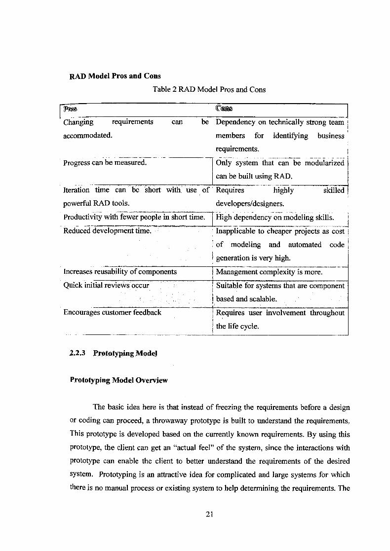
RAD Model Pros and Cons
Table 2 RAD Model Pros and Cons
Changing requirements
accommodated.
Progress can be measured.
Iteration time can be short
can be Dependency on technically strong team
members for identifying business
requirements.
1 Only system that can be modularized
can be built using RAD.
ith. use of Requires highly skilled
powerful RAD tools, developers/designers.
Productivity with fewer people in short time. High dependency on modeling skills.
Reduced development time.
Increases reusability of components
Quick initial reviews occur
Encourages customer feedback
Inapplicable to cheaper projects as cost
of modeling and automated code
generation is very high.
Management complexity is more.
Suitable for systems that are component
1 based and scalable.
Requires user involvement throughout
the life cycle.
2.2.3Prototyping Model
Prototyping Model Overview
The basic idea here is that instead of freezing the requirements before a design
or coding can proceed, a throwaway prototype is built to understand the requirements..
This prototype is developed based on the currently known requirements. By using this
Prototype, the client can get an "actual feel" of the system, since the interactions with
Prototype can enable the client to better understand the requirements of the desired
system. Prototyping is an attractive idea for complicated and large systems for which
there is no manual process or existing system to help determining the requirements. The
21

prototype is usually not complete systems and many of the details are not built in the
prototype. The goal is to provide a system with overall functionality.
Prototyping Model Design
___jJWdjD
ENEMY
End
-Figure 3 Prototyping Model
22
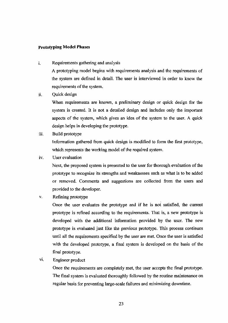
Prototyping Model Phases
L Requirements gathering and analysis
A prototyping model begins with requirements analysis and the requirements of
the system are defined in detail. The user is interviewed in order to know the
requirements of the system.
ii. Quick design
When requirements are known, a preliminary design or quick design for the
system is created. It is not a detailed design and includes only the important
aspects of the system, which gives an idea of the system to the user. A quick
design helps in developing the prototype.
iii. Build prototype
Information gathered from quick design is modified to form the first prototype,
which represents the working model of the required system.
iv. User evaluation
Next, the proposed system is presented to the user for thorough evaluation of the
prototype to recognize its strengths and weaknesses such as what is to be added
or removed. Comments and suggestions are collected from the users and
provided to the developer.
V. Refining prototype
Once the user evaluates the prototype and if he is not satisfied, the current
prototype is refined according to the requirements. That is, a new prototype is
developed with the additional information provided by the user. The new
prototype is evaluated just like the previous prototype. This process continues
until all the requirements specified by the user are met. Once the user is satisfied
with the developed prototype, a final system is developed on the basis of the
final prototype.
vi. Engineer product
Once the requirements are completely met, the user accepts the final prototype.
The final system is evaluated thoroughly followed by the routine maintenance on
regular basis for preventing large-scale failures and minimizing downtime.
23

Prototypiflg Model Pros and Cons
Table 3 Prototyping Model Pros and Cons
Increased user involvement in the product Risk of insufficient requirement analysis
even before implementation
Since a working model of the system is
displayed, the users get a better
understanding of the system being
developed.
Reduces time and cost as the defects can
be detected much earlier.
Quicker user feedback is available leading
to better solutions.
owing to too much dependency on
prototype
Users may get confused in the prototypes
and actual systems.
Practically, this methodology may
increase the complexity of the system as
scope of the system may expand beyond
original plans.
Developers may try to reuse the existingi
prototypes to build the actual system, even
when it's not technically feasible
Missing functionality can be identified The effort invested in building prototypes
easily may be too much if not monitored
properly
Confusing or difficult functions can be
identified
24

2.3 Tools Used
2.3.1 Microsoft Word 2013
Microsoft Word 2013 is a word processing software used to manage document contents
including text, images, and videos material. This software is included inside Microsoft
Office Professional 2013 suite installed in my workplace computer.
2.3.2 Microsoft PowerPoint 2013
Microsoft PowerPoint 2013 is a slide presentation software used to manage slide deck
contents and allow user to customize the slide design. This software is included inside
Microsoft Office Professional 2013 suite installed in my workplace computer.
2.3.3 Microsoft Project 2013
Microsoft Project 2013 is a project management tool used to produce timeline-based
diagrams for instance, Gantt chart, etc. This software is included inside Microsoft
Office Professional 2013 suite installed in my workplace computer.
2.4 Conclusion
This chapter is discuss the existing system and development methodology. There
are pros and cons in each part and included explanation on development methodology.
Based on the explanation, it could help us to make the better solution and decision for
develop the system.
25
CHAPTER 3
METHODOLOGY
This chapter discuss the overall approach and framework of research which covers the
method, technique, or approach to be used. The first part discusses on the selected
methodology during the development of research and explained about the method,
techniques, tools, instruments, etc. which were used in this research. The second part
defines both the hardware and software that are used in this project. Also, justification
on the importance of selected hardware and software. The last part includes a Gantt
chart to illustrate the phases' projection till project completion with estimated duration
for each phases.
3.1 Methodology
The software development model that I will use to develop my system is the Rapid
Application Development Model (RAD) which I had mentioned and explain in another
chapter. The phases of the RAD model contain:
A) Requirement Planning
B) User Design
C) Construction
D) Transition / Cutover
26