multi-scale modeling of grouted sand behavior
TRANSCRIPT

International Journal of Solids and Structures 45 (2008) 4362–4374
Contents lists available at ScienceDirect
International Journal of Solids and Structures
journal homepage: www.elsevier .com/locate / i jsols t r
Multi-scale modeling of grouted sand behavior
Pierre-Yves Hicher a, Ching S. Chang b,*, Christophe Dano a
a Research Institute in Civil and Mechanical Engineering, UMR CNRS, Ecole Centrale Nantes, Université de Nantes, Nantes, Franceb Department of Civil Engineering, University of Massachusetts, Amherst, MA 01003, USA
a r t i c l e i n f o a b s t r a c t
Article history:Received 14 August 2007Received in revised form 26 February 2008Available online 8 April 2008
Keywords:Grouted sandMicrostructural modelStress–strain relationshipCementation damage
0020-7683/$ - see front matter � 2008 Elsevier Ltddoi:10.1016/j.ijsolstr.2008.03.024
* Corresponding author.E-mail address: [email protected]
The mechanical properties of sand: stiffness, cohesion and, to a less extent, friction anglecan be increased through the process of grouting. A constitutive model adapted for cohe-sive-frictional materials from a homogenization technique which allowed us to integrateconstitutive relations at the grain level has been developed to obtain constitutive equationsfor the equivalent continuous granular medium. A representative volume was obtained bymobilizing particle contacts in all orientations. Thus, the stress–strain relationship could bederived as an average of the behavior of these local contact planes. The local behavior wasassumed to obey a stress-dependent elastic law and Mohr–Coulomb’s plastic law. Theinfluence of the cement grout was modeled by means of adhesive forces between grainsin contact, which were added to the contact forces created by an external load. The inten-sity of these adhesive forces is a function of nature and amount of grout present inside thematerial and can be reduced due to a damage mechanism at the grain contact during load-ing. In this paper, we present several examples of simulation which show that the modelcan reproduce with sufficient accuracy the mechanical improvement induced by groutingas well as the damage of the grain cementation during loading.
� 2008 Elsevier Ltd. All rights reserved.
1. Introduction
Microstructural models for inelastic stress–strain behavior of granular material can be derived from properties of inter-particle contacts. If we take the mean behavior of all contacts in each orientation, the overall stress strain behavior can beobtained as an average of the contact behavior for all orientations. The basic idea is to view the packing as represented by aset of micro-systems. The inelastic behavior of each micro-system is characterized and the overall stress–strain relationshipof the packing is obtained from an average of the behaviors of all the micro-systems. Micro-systems can be regarded as inter-particle planes (or mobilized planes) in the packing. Models based on inter-particle contact planes can be found in Jenkinsand Strack (1993), Matsuoka and Takeda (1980), Chang et al. (1989), etc. An alternative way is to view the micro-systems asparticle groups of different configurations. Models developed along this line can be found in Chang et al. (1992a,b), and morerecently in Suiker and Chang (2004).
The microstructural plasticity model requires a mathematical or numerical description of the micro-systems, which is notreadily available in the case of particle groups. But, in order to treat micro-systems as contact or mobilized planes, the ap-proach of estimating the overall behavior by oriented planes can be linked to G.I. Taylor’s (1948) concept, developed long agoin the slip theory of plasticity for polycrystalline materials by Batdorf and Budianski (1949). These ideas were applied byPande and Sharma (1982) to rocks and soils in what they called the overlay model, and to concrete by Bazant et al.(1995) in the so-called microplane model.
. All rights reserved.
(C.S. Chang).

P.-Y. Hicher et al. / International Journal of Solids and Structures 45 (2008) 4362–4374 4363
Along these lines, we have developed a new stress–strain model which considers inter-particle forces and displacements(Chang and Hicher, 2005). A micro–macro link has been incorporated into the model between strain and inter-particle dis-placements for granular materials (Liao et al., 1997). By comparing predicted and measured triaxial loading results for sandsof different void ratios and under different confining stresses, in both drained and undrained conditions, we demonstratedthe ability of this model to reproduce the main features of fully saturated or dry sand behavior (Chang and Hicher, 2005).
The construction of underground structures on soft ground often requires the soil to be improved in order to ensure thesafety and the stability of surrounding buildings. Grout permeation is an efficient technique for reducing permeability andfor increasing stiffness and strength of coarse-to-medium grained soils with low initial mechanical properties. Since tradi-tional organic grouts, such as silicate gels, have proved to be hazardous for groundwater, they have been prohibited over theyears. New grouts, therefore, such as very fine cement suspensions and mineral grouts, have been developed for about thepast 20 years (Zebovitz et al., 1989; Benhamou, 1994). These new grouts present similar groutability performance as do pre-vious chemical solutions. Their considerable advantage is that they prove to be stable with time. We can therefore take intoaccount their improved mechanical properties in design. Experimental studies have shown that cementation in sands,including grouted sands, influences their mechanical properties by adding cohesion and tensile strength, increasing stiffness,without changing significantly the friction angle (Airey, 1993; Clough and Sitar, 1981; Dano, 2001; Dano et al., 2004).
In order to be able to model the mechanical behavior of cohesive-frictional material, we have extended the capability ofthe microstructural plasticity model by including internal forces at the grain contacts in order to reproduce the effect of grainadhesion. In this paper, the adhesive forces simulate the effects of a cement grout incorporated inside the pores of the gran-ular material.
2. Microstructural model
In this model, we envision a granular material as a collection of contact particles. The deformation of a representativevolume of the material is generated by the mobilization of contact particles in all orientations. Thus, the stress–strain rela-tionship can be derived as an average of the mobilization behavior of local contact planes in all orientations. For contactplanes in the ath orientation, the local forces f a
j and the local movements dai can be denoted as follows: f a
j ¼ ff an ; f
as ; f
at g
and dai ¼ fd
an; d
as ; d
at g, where the subscripts n, s and t represent the components in the three directions of the local coordinate
system as shown in Fig. 1. The direction normal to the plane is denoted as n; the other two orthogonal directions, s and t, aretangential to the plane.
2.1. Inter-particle behavior
2.1.1. Internal adhesive forcesIn order to take into account the effect of cement grout in the pores of the granular material, adhesive forces were added
at each contact point to the local forces determined from the external stresses r applied on the granular assembly. Theamplitude of those forces depends on the nature of the grout and on the concentration of the grout in cement particles.Extensive experimental work performed by Dano (2001) demonstrated the influence of these two parameters on the re-sponse of the grouted sand. Fig. 2 presents the evolution of the unconfined compressive strength Rc of Fontainebleau sandat different density indexes grouted by a cement grout called Intra-J at different cement-to-water mass ratios C=W (see grainsize distribution curve of the cement used in Intra-J grout in Fig. 3). One can see that the compressive strength of the groutedsand follows the same trend as the pure grout.
The amplitude of the adhesive force fad has been correlated to the nature of the cement grout by taking a fraction of theunconfined strength of specimens of pure cement grout prepared at a given concentration C=W . SEM analysis of groutedsand specimens shows that the grout is not equally distributed inside the sand pores (Fig. 4). The adhesive force fad can there-
Fig. 1. Local coordinate at inter-particle contact.

0
2
4
6
8
10
0.1 0.2 0.3 0.4 0.5
Unc
onfin
ed c
ompr
essi
ve s
treng
thR
c (M
Pa)
Cement-to-water ratio, C/W
Symbols = Experimental dataLines = Fitting curves
Pure Grout IJ
Fontainebleau Sand+ Cementitious grout IJ
Id = 78 %
Id = 95 %
Fig. 2. Evolution of the unconfined compressive strength Rc with C/W.
0
20
40
60
80
100
0.001 0.01 0.1 1
Pass
ing
the
siev
e (%
)
Particle size (mm)
FineCement
Spinor A12
FontainebleauSandNE34
SILT & CLAY SANDMediumFine
Fig. 3. Grain size distribution curves of sand and grout.
Fig. 4. SEM photos of grouted Fontainebleau sand sample.
4364 P.-Y. Hicher et al. / International Journal of Solids and Structures 45 (2008) 4362–4374
fore represent only a statistical mean value of each adhesive force measured at each contact point. This mean value increaseswhen the amount of cement increases inside the pores, due to either a higher cement concentration of the grout or the fil-tration of the cement particles during injection (see Section 5). Based on the results presented in Fig. 4, the compressivestrength of the grout, Rc;PG, is related to the cement-to-water ratio, C=W , as follows:
Rc;PG ¼ A0 �CW
� �B
ð1Þ

P.-Y. Hicher et al. / International Journal of Solids and Structures 45 (2008) 4362–4374 4365
The values of the two parameters A0 and B are determined by matching the experimental data. In the case of the microfinecement grout Intra-J, A0 was found equal to 45.3 MPa and B close to 2.2.
2.1.2. Elastic partThe contact stiffness of an orientation includes normal stiffness, ka
n, and shear stiffness, kar , of the contact plane. The elastic
stiffness tensor is defined by
f aj ¼ kae
ik daek ð2Þ
which can be related to the contact normal and shear stiffness
kaeik ¼ ka
nnai na
k þ kar sa
i sak þ ta
i tak
� �ð3Þ
The value of the stiffness for two elastic spheres can be estimated from Hertz–Mindlin’s formulation (Mindlin, 1969). Forsand grains, a revised form can be adopted, given by
kn ¼ kn0fn
Ggl2
!n
; kt ¼ kt0fn
Ggl2
!n
ð4Þ
where Gg is the elastic modulus for the grains, fn is the contact force in normal direction. l is the branch length between thetwo particles. kno; kro and n are material constants.
The presence of adhesive forces on each contact plane affect the elastic properties given by Eq. (4). Effects of adhesiveforces on the contact normal stiffness have been studied by Chang and Misra (1990). They showed that the normal stiffnessof two bonded spheres could be expressed as a function of the normal force at contact and the adhesive force. Since, in ourcase, sand grains cannot be assimilated to spheres and coating is not regularly distributed within the grain assembly, wedecided to adopt a simplified form of the stiffness considering adhesive force
kn ¼ kn0f �n
Ggl2
!n
ð5Þ
with f �n ¼ fn þ nfad ð6Þ
where n represents the relative influence of the adhesive force, function of the surface area of two neighbouring particlescoated by the grout. n increases with the degree of cementation. At low degrees of cementation, the bond area is relativelysmall as the cement coats the particles to form weak bonds between two neighbouring particles. With the addition of ce-ment, the bond area increases and the bonds become stronger, contributing to a higher stiffness of the grouted sand.
Shear modulus of Fontainebleau sand grouted by Intra-J cement was measured by Dano (2001). For unconfined groutedsamples, the elastic shear modulus Gmax was found to be a function of the cement-to-water ratio of the grout (Fig. 5)
GmaxðMPaÞ ¼ 26:8CW
� �1:24
ð7Þ
For computing the stiffness of an unconfined grouted sand (i.e., null external loading), we set fn ¼ 0 in Eqs. (5) and (6). Theinitial stiffness is only due to the existence of adhesive forces from grouting, thus we obtain an elastic modulus proportionalto ðfadÞn. Let us assume that the adhesive force fad is proportional to the unconfined strength of the pure grout Rc;PG. Therefore,the elastic stiffness of a grouted sand is proportional to ðC=WÞBn. A value of B close to 2.2 was found for Intra-J grout (Eq. (1)).
0
2
4
6
8
10
0.15 0.2 0.25 0.3 0.35 0.4 0.45
Gm
ax(G
Pa)
C / W
Gmax
= 26.8 x (C/W)1,24
Fig. 5. Elastic shear modulus of unconfined grouted Fontainebleau sand.

4366 P.-Y. Hicher et al. / International Journal of Solids and Structures 45 (2008) 4362–4374
Since n was found equal to 0.5 for Fontainebleau sand, as for most of the sands, the unconfined elastic modulus of Fontaine-bleau grouted sand could be computed as proportional to C=W at the power 1.1. This value can be compared to the measuredvalue equal to 1.24. Considering the amount of dispersion in the measurement of Rc;PG, especially at high C=W values, theproposed approach seems to give satisfactory results for determining elastic properties of cemented sands.
2.1.3. Plastic partThe elastic behavior does not have a coupling effect (i.e., there is no shear induced by normal movements). However, plas-
tic sliding does not necessarily occur along the tangential direction of the contact plane. The sliding direction may be upwardor downward, and the shear dilation/contraction takes place simultaneously. The dilatancy effect can be described by
ddpn
dDp ¼Tfn� tan /0 ð8Þ
where /0 is a material constant which, in most cases, can be considered equal to the internal friction angle /l. This equationcan be derived by assuming that the dissipation work for a contact plane due to both normal and shear plastic movementsðfnd
pn þ T dDpÞ is equal to the energy loss due to friction ðfn tan /0D
pÞ at the contact. Note that the generalized shear force T andthe rate of plastic sliding dDp can be defined as
T ¼ffiffiffiffiffiffiffiffiffiffiffiffiffiffiffif 2s þ f 2
t
qand dDp ¼
ffiffiffiffiffiffiffiffiffiffiffiffiffiffiffiffiffiffiffiffiffiffiffiffiffiffiffiffiffiffiffiffiðddp
s Þ2 þ ðddp
t Þ2
qð9Þ
The yield function is assumed to be of Mohr–Coulomb type,
Fðfj; jÞ ¼ T � fnjðDpÞ ¼ 0 ð10Þ
where jðDPÞ is an isotropic hardening parameter. The material behaves elastically when Fðfj; jÞ < 0. Whereas Fðfj; jÞ > 0 isinadmissible, Eq. (10) must be satisfied throughout the plastic response of the work hardening material. The work hardeningfunction is defined by a hyperbolic curve in j� Dp plane, which involves two material constants: /p and kp0
j ¼kp0 tan /pD
p
j fn j tan /p þ kp0Dp ð11Þ
Eq. (10) means that when the shear contact force ratio T=fn increases, the plastic sliding Dp occurs. Thus, for an isotropicallyconsolidated specimen, plastic sliding occurs immediately after the shear force is generated. Eq. (11) is a hyperbolic functionasymptotic to the value of tan /p. It is noted that the hyperbolic function has been adopted to describe the shear behaviour ofstress and strain at macro level (see, e.g., Duncan and Chang, 1970). It is assumed that the hyperbolic curve can also describethe shear behaviour at inter-particle contact level.
2.1.4. Interlocking influenceAn important factor in granular modelling is the critical state concept. Under critical state, the granular material will re-
main at constant volume while it is subjected to a continuous distortion. The void ratio corresponding to this state is ec.The critical void ratio ec is a function of mean stress. The relationship has traditionally been written as follows:
ec ¼ C� k logðp0Þ or ec ¼ eref � k logp0
pref
� �ð12Þ
C and k are two material constants, p0 is the mean stress of the packing, and ðeref ; pref Þ is a reference point on the critical stateline.
The internal friction angle /l is a constant for the material. However, the peak friction angle, /p, on a contact plane de-pends on the degree of interlocking by neighbouring particles, which can be related to the state of packing void ratio e by
tan /p ¼ec
e
� �m
tan /l ð13Þ
where m is a material constant (Biarez and Hicher, 1994).For dense packing, the peak frictional angle /p is greater than /l. When the packing structure dilates, the degree of inter-
locking and the peak frictional angle are reduced, which results in a strain-softening phenomenon.
2.1.5. Damage law for the bondsThe evolution of the shear modulus during a triaxial loading on a grouted specimen was measured using bender elements
technique (Dano and Hicher, 2003). After an initial phase of constant stiffness, the results showed a continuous decrease ofthe shear modulus, which was analysed as a damage of the bonded contacts (Fig. 6). Therefore, a damage law was introducedin the expression of the adhesive force amplitude, expressed as follows:
fad ¼ f 0ade�gbðq�dbÞ for q > db ð14Þ
f 0ad being the initial adhesive force, and gb the factor of damage.
q is an equivalent local displacement expressed as

0
1000
2000
3000
4000
5000
0 500 1000 1500 2000 2500 3000
Gm
ax (M
Pa)
Stress deviator q (kPa)
C / W = 0.17
Symbols : experimentsDotted line : numerical simulation
Fig. 6. Evolution of elastic shear modulus during triaxial loading.
P.-Y. Hicher et al. / International Journal of Solids and Structures 45 (2008) 4362–4374 4367
q ¼ffiffiffiffiffiffiffiffiffiffiffiffiffiffiffiffiffiffiffiffiffiffiffiffiffiðbdt
nÞ2 þ D2
qð15Þ
where dtn correspond to the normal displacement in elongation. The value of dt
n is otherwise considered equal to zero. Thishypothesis concerning the influence of the normal displacement in the damage law is linked to the fact that the tensilestrength of the grout is only a small fraction of its compressive strength, which indicates that the rate of damage is muchmore important in traction than in compression, as in all cementitious materials (Dano et al., 2004).
The parameter b represents the relative influence of the normal displacement versus the tangential displacement in thedamage law. Usually, high values of b (>10) are selected, due to a much greater influence of the tensile displacement com-pared to the tangential displacement on the grout damage.
db corresponds to the limit value of q, under which no damage takes place (initial phase of constant stiffness).Therefore, each contact produces a cohesive-frictional behavior. During loading, progressive damage of the cementitious
bond leads to a decrease of adhesive forces, while the frictional shear resistance is progressively mobilized. Fig. 6 shows themodel’s response after the parameters introduced in the damage law, obtained by curve fitting, were determined (Table 2).
2.1.6. Elasto-plastic relationshipWith the elements discussed above, a final incremental stress–strain relations of the material can be derived that includes
both elastic and plastic behavior, given by
_f aj ¼ kap
ik_da
k ð16Þ
Detailed expression of the elasto-plastic stiffness tensor is given in Chang and Hicher (2005).
2.2. Stress–strain relationship
The stress–strain relationship for an assembly can be determined from integrating the behavior of inter-particle contactsin all orientations. In the integration process, a micro–macro relationship is required. Using the static hypotheses, we obtainthe relation between the global strain and inter-particle displacement (we do not consider the finite strain condition)
_uj;i ¼ A�1ik
XN
a¼1
_daj lak ð17Þ
where the branch vector lak is defined as the vector joining the centres of two particles, and the fabric tensor is defined as
Aik ¼XN
a¼1
lai lak ð18Þ
The mean force and moment on the contact plane of each orientation are
_f aj ¼ _rijA
�1ik lakV ð19Þ
In Eq. (19), the stress increment can be obtained by the contact forces and branch vectors for all contacts (Christoffersonet al., 1981; Rothenburg and Salvadurai, 1981), as follows:
_rij ¼1V
XN
a¼1
_f aj lai ð20Þ
4368 P.-Y. Hicher et al. / International Journal of Solids and Structures 45 (2008) 4362–4374
The problem is defined as follows:Initially, we know the global variables (rij and eij) for the assembly and the local variables (f a
j and daj ) for each contact ori-
entation. For any given loading increment, which can be stress control, strain control or mixed mode, 6 out of the 12 vari-ables (Drij and Deij) are unknown. The objective is therefore to determine all global variables (rij and eij) and local variables (f a
j
and daj ) at the end of each load increment. For a system with N inter-particle orientations, the number of unknown is 3N for f a
j
and 3N for daj . The total number of unknown is 3N + 3N + 6.
The following equations must be satisfied:
(1) The local constitutive equation, i.e., Eq. (16): since there are three equations for each contact plane orientation, thetotal number of equations is 3N: N being the total number of inter-particle orientations.
(2) Static hypothesis between global stress and local forces, i.e., Eq. (19): the number of equations is 3N.(3) Strain definition between global strain and local displacement, i.e., Eq. (17). The number of equations is 6 (strain is
symmetric).
The total number of unknowns is the same as the total number of equations. Therefore, a solution can be determined.Using Eqs. (16), (17) and (19), the following relationship between stress increment and strain increment can be obtained
_ui;j ¼ Cijmp _rmp; where Cijmp ¼ A�1ik A�1
mnVXN
a¼1
ðkepjp Þ�1laklan ð21Þ
When the contact number N is sufficiently large in an isotropic packing, the summation of flexibility tensor in Eq. (21) andthe summation of fabric tensor in Eq. (18) can be written in integral form, given by
Cijmp ¼ A�1ik A�1
mnNV2p
Z p=2
0
Z 2p
0kep
jp ðc; bÞ�1lkðc; bÞlnðc; bÞ sin cdcdb; and ð22Þ
Aik ¼N2p
Z p=2
0
Z 2p
0liðc; bÞlkðc; bÞ sin cdcdb ð23Þ
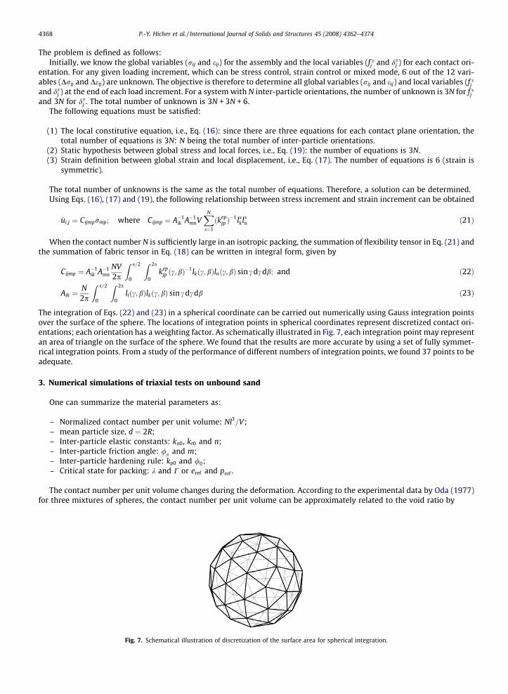
The integration of Eqs. (22) and (23) in a spherical coordinate can be carried out numerically using Gauss integration pointsover the surface of the sphere. The locations of integration points in spherical coordinates represent discretized contact ori-entations; each orientation has a weighting factor. As schematically illustrated in Fig. 7, each integration point may representan area of triangle on the surface of the sphere. We found that the results are more accurate by using a set of fully symmet-rical integration points. From a study of the performance of different numbers of integration points, we found 37 points to beadequate.
3. Numerical simulations of triaxial tests on unbound sand
One can summarize the material parameters as:
– Normalized contact number per unit volume: Nl3=V;
– mean particle size, d ¼ 2R;– Inter-particle elastic constants: kn0, kt0 and n;– Inter-particle friction angle: /l and m;– Inter-particle hardening rule: kp0 and /0;– Critical state for packing: k and C or eref and pref .
The contact number per unit volume changes during the deformation. According to the experimental data by Oda (1977)for three mixtures of spheres, the contact number per unit volume can be approximately related to the void ratio by
Fig. 7. Schematical illustration of discretization of the surface area for spherical integration.

0
0.2
0.4
0.6
0.8
1
1.2
1.4
0 2 4 6 8 10 12
Fontainebleau Sand
O.1 MPa exp0.2 MPa exp0.4 MPa exp0.1 MPa num0.2 MPa num0.4 MPa numq
(MPa
)
eps1 (%)
-7
-6
-5
-4
-3
-2
-1
0
1
0 2 4 6 8 10 12
Fontainebleau Sand0.1 Mpa exp0.2 MPa exp0.4 MPa exp0.1 MPa num0.2 MPa num0.4 MPa num
espv
(%)
eps1 (%)
Fig. 8. Numerical simulations of triaxial tests on Fontainebleau sand.
Table 1Material parameters for Fontainebleau sand
eref pref (kPa) k /l (�) /0 (�) m
0.95 10 0.03 33 29 0.5
P.-Y. Hicher et al. / International Journal of Solids and Structures 45 (2008) 4362–4374 4369
NV¼ 3
2pr3ð1þ eÞe ð24Þ
This equation is used to account for the evolution of contact number per unit volume.Elastic parameters can be determined by using a standard procedure (Hicher and Chang, 2006). Plastic and frictional
parameters were determined from experimental results on ungrouted sand. Other than critical state parameters, all the plas-tic parameters are related to inter-particle behavior. Standard values for kp0 are the following: kp0 ¼ kn0. Therefore, for dry orsaturated samples, only six parameters have to be determined from experimental results, which can all be determined fromthe stress–strain curves obtained from drained or undrained compression triaxial tests.
Drained triaxial tests have been performed by Dano (2001) on dense Fontainebleau sand (density index ID = 0.85). Fon-tainebleau sand is a uniform fine siliceous sand with sub-angular particles of mean size d50 = 0.22 mm (see grain size distri-bution curve in Fig. 3). Fig. 8 presents the results of three triaxial tests at three different confining stresses. Numericalsimulations were performed using the set of material parameters summarized in Table 1. The predictions show good com-parison with experimental results up to 4% of strain. After 4% strain, the experimental data show a moderate softeningbehavior, which may be due to strain localization. The present constitutive model is for a material point, which is not capableto capture non-homogeneous strain within a specimen.
4. Numerical simulations of triaxial tests on grouted sands
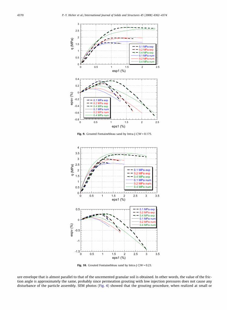
We present in Figs. 9 and 10 two examples of Fontainebleau sand (Id = 0.95) samples reinforced by cement grout Intra-J attwo different concentrations C=W ¼ 0:17 and 0.23. The influence of the cement content in the sand pores can be seen by theincrease of the material strength with the increase of C=W at every confining stress.
The macroscopic cohesion c due to cemented intergranular bonds and the friction angle u due to inter-particle frictionalcontacts are determined by plotting the maximum strength envelope in the Mohr–Coulomb diagram (Fig. 11). For unce-mented granular soils, one obtains a straight-line failure envelope with zero cohesion. For grouted sands, a straight-line fail-
0
0.5
1
1.5
2
2.5
3
0 0.5 1 1.5 2 2.5
0.1 MPa exp0.2 MPa exp0.4 MPa exp0.1 MPa num0.2 MPa num0.4 MPa num
q (M
Pa)
esp1 (%)
-0.8
-0.6
-0.4
-0.2
0
0.2
0.4
0 0.5 1 1.5 2 2.5
0.1 MPa exp0.2 MPa exp0.4 MPa exp0.1 MPa num0.2 MPa num0.4 MPa num
epsv
(%)
eps1 (%)
Fig. 9. Grouted Fontainebleau sand by Intra-J C/W = 0.175.
0
0.5
1
1.5
2
2.5
3
3.5
4
0 0.5 1 1.5 2 2.5 3 3.5
0.1 MPa exp0.2 MPa exp0.4 MPa exp0.1 MPa num0.2 MPa num0.4 MPa num
q (M
Pa)
eps1 (%)
0 0.5 1 1.5 2 2.5 3 3.5eps1 (%)
-1.5
-1
-0.5
0
0.5 0.1 MPa exp0.2 MPa exp0.4 MPa exp0.1 MPa num0.2 MPa num0.4 MPa num
espv
(%)
Fig. 10. Grouted Fontainebleau sand by Intra-J C/W = 0.23.
4370 P.-Y. Hicher et al. / International Journal of Solids and Structures 45 (2008) 4362–4374
ure envelope that is almost parallel to that of the uncemented granular soil is obtained. In other words, the value of the fric-tion angle is approximately the same, probably since permeation grouting with low injection pressures does not cause anydisturbance of the particle assembly. SEM photos (Fig. 4) showed that the grouting procedure, when realized at small or

0
0.5
1
1.5
0 1 2 3σ (MPa)
SFSF+M3
SF+M2
SF+M1
FS : Pure Fontainebleau sandM1 : cement grout C/W = 0.07M2 : cement grout C/W = 0.11M3 : cement grout C/W = 0.15
τ (M
Pa)
Fig. 11. Mohr–Coulomb maximum strength envelopes for pure and grouted Fontainebleau sand.
Table 2Material parameters for Intra-J grout C=W ¼ 0:175
f 0ad n gb db b
0.01 20 0.003 0.0001 40
Table 3Material parameters for Intra-J grout C=W ¼ 0:23
f 0ad n gb db b
0.015 25 0.003 0.0001 40
P.-Y. Hicher et al. / International Journal of Solids and Structures 45 (2008) 4362–4374 4371
moderate values of the injection pressure, does not modify the initial position of the grains. The grout is located inside thepores, but does not penetrate the contact area between two grains. This can explain the minor influence of grouting on thefrictional properties of grouted sands. Similar results have been found by Dupas and Pecker (1979) on mortars, and by Cloughand Sitar (1981) on natural weakly cemented sands. The slight increase of the friction angle can be associated to the decreaseof the void ratio with grout impregnation. The macroscopic cohesion c, corresponding to the intersection of the maximumstrength envelope with the axis of the ordinates in the Mohr plane, increases with the cement-to-water ratio C=W of thegrout.
Numerical simulations were performed with the set of elasto-plastic parameters determined in Table 1 for non-cementedFontainebleau sand. The additional five parameters for the grout behavior are
f 0ad: initial adhesive force;n: mobilised bonded surface;gb: damage factor;db: limit strain value of induced damage;b: relative influence of elongated displacement versus sliding on grout damage.
They were determined from the stiffness decay curves (see example in Fig. 6). They are presented in Tables 2 and 3. Acomparison with experimental results in Figs. 9 and 10 shows that the model is capable of reproducing with sufficient accu-racy the mechanical behavior of grouted Fontainebleau sand. The difference in initial stiffness between experimental andnumerical results is mainly due to the compliance of the loading frame which induced higher measured axial displacement.Its influence can also be seen on the beginning of the e1–ev curves.
5. Influence of cement content
Maalej (2007) studied the microstructure of the material using scanning electron microscopy and mercury porosimetry.He was able to quantify very precisely the amount of cement grout inside the sand pores after injection. For a given cementgrout at a given concentration C=W , this amount can vary during the grouting process, due to the filtration of cement par-ticles inside the sand pores. As a consequence, the concentration of the cement particles is higher near the point of injectionand decreases when the distance towards the injection point increases.
Figs. 12 and 13 present experimental results and numerical simulations, respectively, for grouted Fontainebleau sandspecimens with different cement contents under a confining pressure equal to 0.8 MPa. The volumetric cement concentra-tion varied from 0.22 in specimen 1 to 0.075 in specimen 5. The adhesive forces could be correlated to the cement contentusing a single linear relation

0
2
4
6
8
10
0 1 2 3 4 5
C23.1C23.2C23.3C23.4C23.5
q (M
Pa)
eps1 (%)
-2.5
-2
-1.5
-1
-0.5
0
0.5
0 1 2 3 4 5
C23.1C23.2C23.3C23.4C23.5
epsv
(%)
esp1 (%)
Fig. 12. Grouted Fontainebleau sand. Experimental results for different grout concentrations.
0
2
4
6
8
10
0 1 2 3 4 5
C23.1C23.2C23.3C23.4C23.5
q (M
Pa)
eps1 (%)
-2.5
-2
-1.5
-1
-0.5
0
0.5
0 1 2 3 4 5
C23.1C23.2C23.3C23.4C23.5
epsv
(%)
eps1 (%)
Fig. 13. Grouted Fontainebleau sand. Numerical results for different grout concentrations.
4372 P.-Y. Hicher et al. / International Journal of Solids and Structures 45 (2008) 4362–4374
f 0ad ¼ 0:151 ðf in NÞ ð25Þ
f being the volumetric cement concentration (if e0 is the initial sand void ratio and ef the void ratio after grouting,f ¼ e0 � ef ).

Fig. 14. Grout concentration at a given time after the beginning of the injection process.
P.-Y. Hicher et al. / International Journal of Solids and Structures 45 (2008) 4362–4374 4373
This linear relation is in agreement with the results presented by Maalej (2007), which has showed that a linear relationcould be found between the macroscopic cohesion c and the cement content f. It is therefore possible to predict the mechan-ical properties of an in situ grouted sand by taking into account the filtration process around the point of injection.
Chupin et al. (2003, in press) developed a model of transport with filtration in saturated porous media. The model is basedon the advection–dispersion equation of miscible fluids and considers a phenomenological approach for the purpose of fil-tration. The permeability reduction of the porous medium, as a result of the filtration phenomenon, depends on the concen-tration of the filtrated component. The kinetic equation of filtration is assumed to be a function of the transportedcomponent. The resulting coupled system of equations was discretized by finite elements. Fig. 14 shows an example of anumerical simulation of grout propagation with filtration condition inside a sand volume. The cement grout was injectedat a given point of the medium and the grout propagation was measured as a function of time. The figure shows that thegrout concentration is higher near the point of injection due to the filtration of cement grains inside the sandy medium.
6. Conclusion
We have adapted a microstructural model developed for non-cohesive granular materials to the mechanical behavior ofgrouted sand. The model is based on the description of the inter particulate contact law which requires a simple relationbetween the vectors of forces and the relative displacements on a contact plane. Deformation of a representative volumeis obtained by mobilizing particle contacts in all orientations. Thus, the stress–strain relationship can be derived as an aver-age of the behavior of these local contact planes.
The introduction of grouting influence was made by introducing an adhesive force at each grain contact, function of thenature and concentration of the cement grout. Experimental results demonstrated that the intensity of these adhesive forcesdecreased during mechanical loading. Therefore, a damage mechanism was introduced at each grain contact. The intensity ofthe damage was taken as a function of the relative displacement of two contacting grains.
4374 P.-Y. Hicher et al. / International Journal of Solids and Structures 45 (2008) 4362–4374
Numerical simulations of triaxial tests demonstrated the ability of this new version of the model to reproduce themechanical properties of grouted Fontainebleau sand with various cement grout concentrations. An original aspect of thismulti-scale modeling is the model’s capacity to take into account the influence of cement concentration in a simple manner.If coupled to a numerical model of grout propagation with filtration, the model can provide the spatial evolution of themechanical properties of a sand layer impregnated by a cement grout, employing ordinary in situ injection techniques.
References
Airey, D.W., 1993. Triaxial testing of naturally cemented carbonate soil. Journal of Geotechnical Engineering 119 (9), 1379–1398.Batdorf, S.B., Budianski, B., 1949. A mathematical theory of plasticity based on concept of slip. NACA Tech note TN 1871.Bazant, Z.P., Xiang, Y., Ozbolt, J., 1995. Nonlocal microplane model for damage due to cracking. In: Proceedings of Engineering Mechanics, vol. 2, pp. 694–
697.Benhamou, O., 1994. Comportement rhéologique des coulis de liants hydrauliques ultrafins destinés à l’injection. Ph.D. Thesis, Ecole de Géologie de
l’Ingénieur, Ecole Nationale Supérieure des Mines de Paris (in French).Biarez, J., Hicher, P.-Y., 1994. Elementary Mechanics of Soil Behaviour. Balkema. p. 208.Chang, C.S., Misra, A., Weeraratne, S.P., 1989. A slip mechanism based constitutive model for granular soils. Journal of Engineering Mechanics, ASCE 115 (4),
790–807.Chang, C., Misra, A., 1990. Micromechanical modeling of cemented sands under low amplitude oscillations. Geotechnique 40 (2), 251–263.Chang, C.S., Kabir, M., Chang, Y., 1992a. Micromechanics modelling for the stress strain behavior of granular soil-II: evaluation. Journal of Geotechnical
Engineering, ASCE 118 (12), 1975–1994.Chang, C.S., Misra, A., Acheampon, K., 1992b. Elastoplastic deformation of granulates with frictional contacts. Journal of Engineering Mechanics, ASCE 118
(8), 1692–1708.Chang, C.S., Hicher, P.-Y., 2005. An elastoplastic model for granular materials with microstructural consideration. International Journal of Solids and
Structures 42 (14), 4258–4277.Chupin, O., Saiyouri, N., Hicher, P.Y., 2003. Numerical modeling of cement grout in saturated porous media, In: Proccedings of the 16th ASCE Engineering
Mechanics Conference, Seattle.Chupin, O, Saiyouri, N., Hicher, P.Y., in press. The effects of filtration on the injection of cement-based grouts in sand columns, Transport in Porous Media.Clough, G.W., Sitar, B., 1981. Cemented sand under static loading. Journal of the Geotechnical Engineering 107 (GT6), 799–817.Christofferson, J., Mehrabadi, M.M., Nemat-Nassar, S., 1981. A micromechanical description on granular material behavior. ASME Journal of Applied
Mechanics 48, 339–344.Dano, C., 2001. comportement mécanique des sols injectés, thèse de Doctorat de l’Université de Nantes et de l’Ecole Centrale de Nantes.Dano, C., Hicher, P.Y., 2003. Behavior of uncemented soils and grouted soils before maximum shear strength. Soils and Foundations 43 (4), 13–20.Dano, C., Hicher, P.Y., Tailliez, S., 2004. Engineering properties of grouted sands. Journal of Geotechnical and Environmental Engineering, ASCE 130 (3), 328–
338.Duncan, J.M., Chang, C., 1970. Nonlinear analysis of stress and strain in soils. Journal of Soil Mechanics and Foundation Engineering, ASCE 96 (5), 1629–1653.Dupas, J.M., Pecker, A., 1979. Static and dynamic properties of sand-cement. Journal of the Geotechnical Engineering Division Proceedings of the American
Society of Engineers 105 (3), 419–436.Hicher, P.-Y., Chang, C.S., 2006. an anisotropic non linear elastic model for particulate materials. Journal of Geotechnical Engineering, ASCE 132 (8).Jenkins, J.T., Strack, O.D.L., 1993. Mean-field inelastic behavior of random arrays of identical spheres. Mechanics of Material 16, 25–33.Liao, C.L., Chang, T.P., Young, D., Chang, C.S., 1997. Stress–strain relationship for granular materials bases on hypothesis of best fit. International Journal of
Solids and Structures 34 (31–32), 4087–4100.Maalej, Y., 2007. Comportement mécanique d’un milieu granulaire injecté par un coulis de ciment: étude expérimentale et modélisation micromécanique”,
thèse de Doctorat de l’Ecole Nationale des Ponts et Chaussées.Matsuoka, H., Takeda, K., 1980. A stress–strain relationship for granular materials derived from microscopic shear mechanisms. Soils and Foundation 20 (3),
45–58.Mindlin, R.D., 1969. Microstructure in linear elasticity. Archive for Rational Mechanics and Analysis 16, 51–78.Oda, M., 1977. Co-ordination number and its relation to shear strength of granular material. Soils and Foundations 17 (2), 29–42.Pande, G.N., Sharma, K.G., 1982. Multi-laminate model of clays – a numerical evaluation of the influence of rotation of the principal stress axis. In: Saxena,
S.K., Desai, C.S. (Eds.), Proceedings of Symposium on Implementation of Computer Procedures and Stress–Strain Laws in Geotechnical Engineering.Acorn Press, Chicago, Durham, NC, pp. 575–590.
Rothenburg, L., Selvadurai, A.P.S., 1981. Micromechanical definition of the Cauchy stress tensor for particulate media. In: Selvadurai, A.P.S. (Ed.), Mechanicsof Structured Media. Elsevier, Amsterdam, The Netherlands, pp. 469–486.
Suiker, A.S.J., Chang, C.S., 2004. Modelling failure and deformation of an assembly of spheres with frictional contacts. Journal of Engineering Mechanics,ASCE 130 (3), 283–293.
Taylor, D.W., 1948. Fundamentals of Soil Mechanics. J. Wiley and Sons, NewYork, NY.Zebovitz, S., Krizek, R.J., Atmatzidis, D.K., 1989. Injection of fine sands with very fine cement grout. Journal of Geotechnical Engineering 115 (12), 1717–
1733.