mts centrifuge - biomedical manuals...the mts centrifuge model 5150-60 is a table top centrifuge...
TRANSCRIPT

MTS Centrifuge
Model 5150-60
Service Manual
PK101.doc OCD CTS part number: 50000104
Cat Number: 6902119


Table of Contents
Section 1. General Information 1
1.1 Centrifuge Application 21.2 Contents 21.3 Specifications 21.4 Safety Procedures 31.5 Parts List and Exploded View 41.6 Troubleshooting: 7
Front Panel: LED 7 Front Panel: Time Display 7 Front Panel: RPM Display 8 General 9
Section 2. Equipment Installation 11
2.1 Choice of Location 122.2 Unpacking and Installation 12
Section 3. Diagrams 13
3.1 Centrifuge Schematic 143.2 Main PCB Schematic 153.3 Display PCB Schematic 163.4 Main Wiring Diagram 173.5 Back Panel Wiring Diagram 18
Section 4. Removal Instructions 19
4.1 Drawer 19

Section 5. Removal Instructions - 20 Front Panel
5.1 Membrane Switch Removal 205.2 LED Assembly Removal 205.3 Display PC Board Removal 205.4 Display Bezel Removal 21
Section 6. Removal Instructions - 22
Spindle / Pulley Assemblies
6.1 Belt Removal 226.2 Motor Pulley Removal 236.3 Rotor Pulley Removal 236.4 Spindle Assembly Removal 24
Section 7. Removal Instructions - 25
Main Electronics
7.1 Ribbon Cable Removal 257.2 Main Board Assembly Removal 257.3 Motor Removal 267.4 Capacitor Removal 267.5 Transformer Removal 277.6 Latch Mechanism Removal 277.7 Terminal Block Connector Removal 287.8 Retractile Cable Removal 297.9 Cable Hanger Removal 31
Section 8. Removal Instructions - 32
Back Panel
8.1 Latch Strike Removal 328.2 Power Inlet / Power Switch Removal 338.3 Retractile Cable Removal
(Back Panel Side) 33
8.4 Retractile Cable Plate Removal 34

Section 9. Removal Instructions - 35 Cabinet
9.1 Tachometer Cap Removal 359.2 Rubber Feet Removal 359.3 Rubber Seal Removal 35
Section 10. Centrifuge Quality Control 36
10.1 Speed Quality Control 3610.2 Centrifuge Time Quality Control 36

This page intentionally blank.

1
1. General Information
Applications Contents Specifications Safety pointers Parts list Troubleshooting guide

2
1.1 Centrifuge Application The MTS Centrifuge Model 5150-60 is a table top centrifuge controlled by solid state electronics which has been designed for the required centrifugation of MTS Gel Cards. Notice: Only MTS Gel Cards manufactured by Micro Typing Systems may be used in this Centrifuge. This device centrifuges the MTS Gel Cards for 10 minutes at an RPM of 895 + 25. Recommendations for the verification of RPM and centrifugation time can be found in Chapter 10: Centrifuge Quality Control. 1.2 Contents of original shipment 1 MTS Centrifuge Model 5150-60 1 MTS 24 place Rotor Head 1 Power Cord 1 Operating Manual 1 MTS 515060 Belt / Fuse Spares Kit 1.3 Specifications Please find below the specifications of the MTS Centrifuge Model 5150-60 Measurements: Height = 5.75 in (14.37 cm) Width = 13.50 in (33.75 cm) Depth = 19.25 in (48.12 cm) Weight: 14 lb. (6.36 Kg) Nominal Voltage: 110-120 60 Hz Fuse: 3.0 A 250 VAC Speed: 895 rpm + 25rpm (80 - 90 RCF) Centrifugation time: 10 Minutes + 10 seconds LED Displays: Time Remaining and RPM MTS Gel Card Capacity: 24 Cards Operating Temperature: Temperature 5 - 40o C Color: PMS Gray 400U

3
1.4 Safety Procedures MTS can only ensure safety, reliability and efficiency of the MTS Centrifuge when the following safety measures are followed. * Read the Operating Manual before installing the Centrifuge. * Instrument repair and service should only be performed by authorized and qualified servic engineers
designated by the manufacturer. * After each repair, complete the Quality Control checks located in section 10 of this manual. * The electrical safety of the equipment can only be ensured when plugged into a grounded
receptacle that has been installed in the building which meets the national standards and when the equipment is used in an area designed for normal laboratory functioning. It should not be used in an oxygen rich area.
* Do not allow liquid to enter the instrument. * The centrifugation of materials other than MTS Gel Cards is strictly prohibited. * The MTS Centrifuge should not be combined with other devices. However, the MTS Incubator can be
placed on top of the centrifuge cabinet. * Only spare parts from Micro Typing Systems, Inc. may be used. * Never attempt to open the drawer while the rotor is spinning. Personal injury and machine damage is
possible if this centrifuge is operated with a head not specified by Micro Typing Systems, Inc.

4
1.5 Parts List
Ref. # Item Key # Description Qty U/M
1 492-155050 Cover, Cabinet Silk-screened 1 ea 2 765-435760 Hanger, Rubber Seal (3 Part) 1 set 3 771-782200 Seal, Rubber 19.5 in 4 750-731000 Rail, Drawer Glide 2 ea 5 771-125810 Cap, Tachometer Hole 1 ea 6 750-285790 Feet, rubber suction 4 ea 8 454-123745 S/A Retractile Cable 1 ea 9 765-798540 Strike, Latch 1 ea
11 731-485020 Inlet, Power 1 ea 12 731-333152 Fuse, 3 Amp, 5 x 20 mm 2 ea 14 750-285820 Rubber Protector 1.5 in 15 762-410000 Label, Ground 2 ea 17 750-731000 Drawer Glide Male 2 ea 18 731-805220 Switch, Membrane 1 ea 19 460-545740 S/A LED, red 1 ea 20 741-337609 Screw, 4-40 x 7/16 ph ph ss 24 ea 27 736-786801 Screw, Set 6-32 x ¼ alloy, cup point 3 ea 28 741-418833 Screw, 6-32 X 3/16, fh slotted undercut ss 8 ea 42 742-401059 Screw, 4 x 10mm 2 ea 52 460-445400 S/A LED, green 1 ea 53 767-062190 Bezel, Display Board 2 ea 54 781-192001 PC Board, Display 1 ea 55 731-789020 Solenoid, Latch 1 ea 56 725-320015 Capacitor, Motor for 60HZ 1 ea 57 731-830080 Transformer, 120 vac, 12 vac, 2 AMP 1 ea 63 728-080000 Connector, Terminal Block 2x 1 ea 64 765-435740 Hanger, Retractile Cable 1 ea
65-66 454-123755 S/A Ribbon Cable 1 ea 65 * Cable, Ribbon 66 * Connector, 34 Pin 67 489-571000 S/A, Main PC Board 1 ea 69 460-588050 S/A Motor 1 ea 70 765-791240 Spindle, For 24 Place 1 ea
71-75 475-798050 S/A Spindle for 24 Place 1 ea 71 * Housing, Spindle 1 ea 72 * Bearing, .375 ID x .875 OD 2 ea 73 * Bushing, spindle 1 ea 74 765-454790 Spacer, spindle housing 1 ea 75 736-789700 Snap Ring Internal .875 ID 1 ea 76 765-695583 Pulley, Motor 1.045" for 24 Place 110V 1 ea 77 765-695750 Pulley, Rotor 2" 1 ea

5
Ref. # Item Key # Description Qty U/M
78 765-930250 Wheel, Encoder 1 ea 79 489-660000 S/A PC Board, Opto 1 ea 80 712-073050 S/A Belt, Round 22 1/8" Circumference 1 ea 81 771-068000 Bezel, Tach Wire 1 ea 82 789-155242 Cover, Front Panel Electronics 1 ea 83 789-155240 Cover, Electronics 1 ea 84 762-927000 Label, warning 1 ea 85 789-155690 Cover, Pulley 1 ea 86 789-155096 Cover, Bottom Cable 1 ea
87-94 475-758050 S/A Rotor 5150 1 ea 87 * Rotor for 24 Place 1 ea 88 771-175240 Cups, for 24 Place 24 ea 89 736-927424 Washer, for 24 Place Rotor 24 ea 90 742-301244 Screw, 3 x 12 mm hex head 24 ea 92 767-466750 Hub, for 24 Place Rotor 1 ea 93 * Pin, Dowel for Rotor Hub 1 ea 94 * Tubing, tygon 1/8" ID X 3/16" OD X 1/32" wall
thickness 1 in
95 712-688000 Cable, Power 1 ea 96 762-780810 Label, Serial Tag 1 ea
N/A 769-130050 Manual, operations 1 ea N/A 609-139055 Packaging Kit-MTS Centrifuge Model 5150 1 ea
* Components marked with an * are available only in the preceding sub-assembly.

6
Refer to Section 1.5 Parts List for Item Key Number

7
1.6 Troubleshooting Front Panel LED Green Power LED does not come Check that the centrifuge is connected to a live power outlet. on when switch is turned on. Check main power. Check power cord. Check fuse contained in power inlet housing. Remove front panel cover and check that connector is connected properly. Replace the connector and/or LED. Time Display Time does not display while Remove front panel cover and check ribbon cable centrifuge is spinning. connection. Remove electronics cover and check ribbon cable connection. Replace ribbon cable. Replace display board. Replace main PC board. Timer starts at a time other than Replace main PC board 9:59.

8
RPM Display RPM does not display while Check opto sensor adjustment. centrifuge is spinning. Remove front panel cover and check ribbon cable connection. Check connections of opto assembly on tach PC board. Check connection of tach PC board to main PC board. Remove electronics cover and check ribbon cable connection. Replace opto assembly. Replace main PC board. RPM flashes erroneous numbers Check opto sensor adjustment. Check connections of opto assembly to tach PC board. Replace opto assembly. Replace main PC board.

9
General
When start button is pressed the Make sure drawer is fully closed and latched. timer begins countdown, but centrifuge does not spin. Check belt. Verify function of latch motor power switch. Replace latch if required. When start button is pressed the Check main power. timer does not begin and the centrifuge does not spin. Wait 1-2 seconds to ensure rotor is not moving, then press start again.
Open front panel cover and check membrane switch connections. Replace membrane switch. Check ribbon cable connections. Replace ribbon cable. Replace main board. When the stop button is pressed Open front panel and check membrane switch the centrifuge continues to run. connections. Replace membrane switch. Check ribbon cable connections. Replace ribbon cable. Replace main board. Motor runs, but red LED does Check connection of LED on display PC board. not light. Check LED assembly by switching with the green LED assembly. If it does not work in this place, replace connector and/or LED. Otherwise replace display PC board.

10
Machine is "noisy". Check rotor pulley to be sure the encoder wheel is not rubbing on the optical interrupter. Check both pulleys to make sure they have not come loose. Check belt for frayed pieces. Note: Some instruments will be noisier than others due to noisy bearings. Once all of the above have been checked and nothing has been found, it can be assumed that the instrument is going to run a little loud. Cell buttons are not flat Cups need to be adjusted. If the centrifuge rotor head has set screws installed for cup adjustment, these screws may have loosened or fallen out. If any of the 24 set screws have loosened or fallen out, all 24 set screws should be completely removed with a hex head screwdriver. The set screws can be replaced with 4-40 x 7/16" pan head philips ss screws and # 4 split lock washers. Install all twenty-four 4-40 x 7/16" screws from the top of the rotor with the # 4 split lock washer between the head of the screw and the rotor plate.The combination of this length screw and washer will produce a flat cell button.

11
2. Equipment Installation
Choice of location Unpacking

12
2.1 Choice of Location Choose a location convenient for routine use which is stable, level and close enough to the power supply so that no extension cord is necessary. It should also be away from direct sunlight and air drafts. (Attention: As with any other electrical device this centrifuge must not be placed near a water faucet. If the machine is placed in the proximity of a water faucet an electrical danger exists.) The MTS Centrifuge is designed for indoor use only. Operating temperatures should be between 5oC and 40oC (Normal ambient room temperature). The main supply voltage should not exceed + 10% of the nominal voltage. 2.2 Unpacking and Installation
Carefully unpack your MTS Centrifuge by following these steps: 1. Remove the rotor head box from the centrifuge box. Carefully open the rotor head box and remove the rotor
head. 2. Remove power cord and place next to rotor head on table. 3. Remove top foam insert from box. 4. Remove centrifuge from box and place on table next to rotor head and power cord. 5. Install the rotor head. Installation The MTS Centrifuge should be placed on a stable and level surface in the designated work area. For best results, the surface of the area should be clean and dry. Attach power cord to centrifuge and plug into power receptacle with the appropriate voltage and frequency. Power line voltage and frequency requirements are shown on the data plate at the rear of the centrifuge. WARNING: Grounding - The MTS Centrifuge is equipped with a three-prong plug for safety purposes. If the intended wall outlet is a grounded (three-wire) type, the instrument will be grounded automatically. If the intended wall outlet is not the grounded type, an approved and properly grounded adapter should be used. Make sure the grounding lead on the adapter is firmly attached to a grounded receptacle box before operating the instrument. Extension cords should also be three-wire type.

13
3. Diagrams
Centrifuge Schematic Main PCB Schematic Display PCB Schematic Main Wiring Diagram Back Panel Wiring Diagram

14
3.1 Centrifuge Schematic
M
120 VAC Input
IEC Connector
Chassis Ground
Power Switch
Door Latch Solenoid
Power Dsitribution Connector
Micro Typing Systems, Inc. Centrifuge Schematic
Starting Capacitor 2.3 uF 250V 50/60Hz
Tachometer PCB
Display PCBOpto-Sensor
Tachometer Wheel
Main PCB
Stop
Start
15
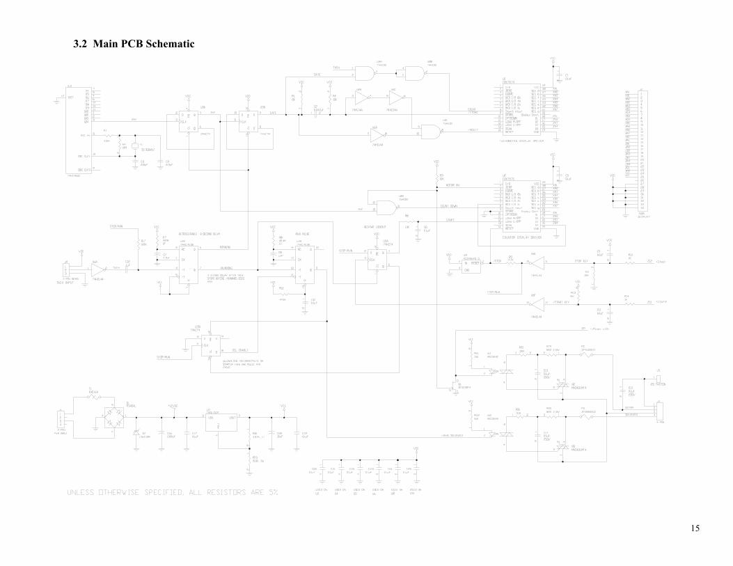
3.2 Main PCB Schematic

16
3.3 Display PCB Schematic
17
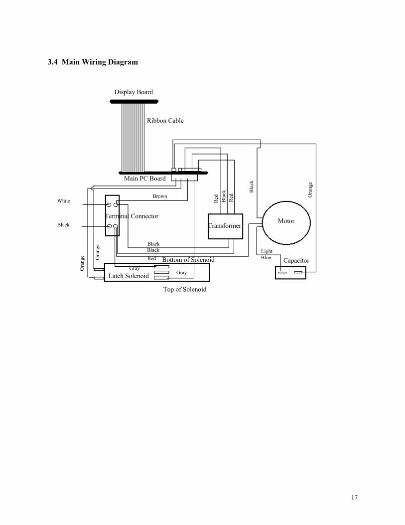
3.4 Main Wiring Diagram
Display Board
Motor Terminal Connector
Transformer
Main PC Board
Latch Solenoid
Capacitor
Gray Gray O
rang
e Ora
nge
White
Black
Red
Black Black Light
Blue
Ora
nge
Brown
Bla
ck
Bla
ck
Red
Red
Top of Solenoid
Ribbon Cable
Bottom of Solenoid

18
3.5 Back Panel Wiring Diagram
Green/Yellow
Black
White
Green
Ground Location
Ground Label Latch Access HoleInside View
Retractile Cable (To Chassis)Latch Strike

19
4. Removal Instructions - Drawer
4.1 Drawer The drawer (or chassis) is mounted to the cabinet with two slide rails. Each rail is secured to the chassis with three 6-32 X 1/4 PH Phillips screws with washers. These screws are put in using permanent (or red) Loctite. The other half of the rail is secured to the cabinet using four 6-32 X 1/8 FH Phillips screws with no washers. These screws are also held in with red Loctite. The chassis may be removed from the cabinet in the following way: Note- make sure that the latch is disengaged and the power cable is removed from the power inlet. Remove the centrifuge rotor. While pulling the drawer out, carefully lift the back of the drawer up to remove it. Carefully set the drawer next to the cabinet in a way as to put as little stress on the retractile cable as possible. The chassis consists of 3 serviceable areas: Ribbon Cable / Spindle-Pulley Main Electronics Area Assemblies
Front Panel Electronics

20
5. Removal Instructions - Front Panel
To access the front panel electronics, remove the front panel cover by removing the four 4-40 nuts from the studs.
5.1 Membrane Switch Removal
1. Disconnect the ribbon cable from the display PC Board. 2. Disconnect the two LED connectors from the display PC Board. 3. Remove the LED assemblies (see section 5.2) . 4. Gently peel the membrane switch from the chassis. 5.2 LED Assembly Removal 1. Loosen the retaining nut behind the LED. 2. Cut the connectors off at the end of the wire. 3. Push the LED assembly through the chassis and remove. 5.3 Display PC Board Removal 1. Disconnect all connectors from the display board. 2. Remove the four 4-40 X 1/4 PH Phillips screws. 3. Remove the PC board. Note- the screws for the PC board are put in with removable (or blue) Loctite.

21
5.4 Display Bezel Removal 1. Remove the display PC board (see section 5.3). 2. Grasp the bezel on both sides and gently remove. If necessary, carefully press on the membrane switch window to pop out the bezel.

22
6. Removal Instructions - Spindle / Pulley Assemblies
To access the spindle / pulley area remove the large cover from underneath the chassis.
6.1 Belt Removal 1. Stretch the belt until it comes off the motor pulley. 2. Remove it from around the rotor pulley, being careful not to bend or damage the encoder wheel.
To re-attach: 1. Wrap it around the rotor pulley and then stretch it until it wraps around the motor pulley.

23
6.2 Motor Pulley Removal
1. Remove the belt (see section 6.1) . 2. Loosen the set screw on the side of the pulley and remove it. To install a new motor pulley: 1. Use a caliper or ruler to measure the height of the rotor pulley. 2. Use this dimension to adjust the motor pulley height. 3. Tighten the set screw and attach the belt. (Note: set screw is installed with blue Loctite.) 6.3 Rotor Pulley Removal
1. Remove the belt (see section 6.1). 2. Using a screw driver loosen the screw of the opto board holder. 3. Gently turn the opto board so that it does not interfere with the rotor pulley. 4. Loosen the set screws on the pulley and remove. 5. Remove the encoder wheel on the pulley by removing the four 6-32 X 1/4 PH Phillips screws. To install a new rotor pulley: 1. Install the encoder wheel on the pulley. 2. Place the pulley assembly on the spindle and gently turn back the opto board holder so that the encoder wheel passes through the opening in the optical interrupter. 3. Tighten the opto board holder. 4. Adjust the pulley so that the encoder wheel passes through the midway point of the optical interrupter. (Note: Be sure the set screw is lined up with the flat part of the spindle shaft.) 5. Tighten the set screws. (Note: set screws are installed with blue Loctite) 6. Install the belt.

24
6.4 Spindle Assembly Removal
1. Remove the rotor pulley (see section 6.3). 2. Remove the four 6-32 X 1/2 screws. 3. Remove the spindle assembly. To replace spindle assembly: 1. Secure assembly to chassis with the four screws and washers using blue Loctite. 2. Replace rotor pulley assembly (see section 6.3).

25
7. Removal Instructions - Main Electronics To access the main electronics area remove electronics cover by removing the three 6-32 X 1/4 PH Phillips screws and washers.
7.1 Ribbon Cable Removal 1. Remove the ribbon cable cover from underneath the chassis by removing the eight 4-40 X 1/4 PH Phillips screws and washers. 2. Remove the front panel electronics cover (see section 1). 3. Carefully disconnect the ribbon cable from the PC boards (Note: Sometimes it is easier to loosen or remove the main PC board to allow better access to the connector.). 4. Remove the ribbon cable from the chassis. To install a new ribbon cable: 1. Feed each end into the chassis from the underside before connecting either end to the PC boards.. 2. Connect the ribbon cable to the main board and then to the display board. (Note: If you loosened or removed the main board from the chassis, now is the time to reinstall it.) 3. Put both the ribbon cable cover and the front panel electronics covers back on. 7.2 Main Board Assembly Removal
1. Remove the two 6-32 X 1/4 PH Phillips screws and washers. 2. Disconnect all wires and connectors. To install a new main board assembly: 1. Connect all wires and connectors. (see wire diagram 3.5) 2. Secure to chassis with screws and blue Loctite.

26
7.3 Motor Removal
1. Remove the motor pulley (see section 6.2). 2. Disconnect all wires and connectors. 3. Loosen and remove the four 10-32 nuts from the underside of the chassis. 4. Remove motor. To install a new motor: 1. Place eight flat washers over the four screw holes (two washers on each hole). 2. Carefully place the motor on top of the washers. (Note: The wire harness of the motor should face the main board.) 3. Dip the four screws in blue Loctite and place them through the holes in the motor. (Note: Make sure all of the washers are in place.) 4. Secure the screws with four nuts and washers from the underside of the chassis. 5. Tighten the nuts. 6. Connect all wires and connectors (see wire diagram 3.6). 7.4 Capacitor Removal 1. Remove the plastic shield as well as the two connectors. 2. Remove the 6-32 X 3/8 PH Phillips screw and washer. 3. Remove capacitor. To install new capacitor: 1. Secure the capacitor to the chassis using the screw and blue Loctite. 2. Connect the two wires and replace the plastic cover.

27
7.5 Transformer Removal
1. Remove the connector from the main board. 2. Remove the two black wires from the terminal block connector. 3. Loosen and remove the two 8-32 X 5/16 screws and washers. 4. Remove transformer. To install a new transformer: 1. Secure the transformer to the chassis with the two screws, washers and blue Loctite (Note: The black wires of the transformer should face the rear of the chassis). 2. Place the connector on the main board. 3. Connect the two black wires to the two terminals of the terminal block connector (Note: It is not important which black wire is connected to which connector.). 7.6 Latch Mechanism Removal
1. Remove all wires and connectors. 2. Remove the two M4 X 10 PH Phillips screws and washers. 3. Remove latch mechanism. To install a new latch mechanism: 1. Secure the latch to the chassis using the two screws, washers and blue Loctite. 2. Replace all wires and connectors (see wiring diagram 3.6). 3. Adjust the latch mounting so that the drawer closes and latches with no interference.

28
7.7 Terminal Block Connector Removal
1. Remove all wires. 2. Remove the 6-32 X 5/8 PH Phillips screw and washer. 3. Remove the connector. To install a new terminal block connector: 1. Secure the connector to the chassis by using the screw, washer and blue Loctite. 2. Replace all wires (see wiring diagram 3.6).

29
7.9 Retractile Cable Sub-Assembly Removal 1. Using a flat head screwdriver, loosen the screws on the terminal block that secure the white and black Retractile
Cable wires. Remove the wires from the terminal block. 2. Using a phillips screwdriver, unscrew the ground location screw that connects the green Retractile Cable wire
to the centrifuge drawer. Place the screw and washer aside for re-assembly. 3. Cut the single tie-wrap that attaches the white, black, green, and orange wires together. 4. Using a phillips head screwdriver, remove the two screws and washers that attach the cable hanger to the
centrifuge drawer. Place the screws and washers aside for re-assembly. 5. The back panel plate is now detached from the centrifuge drawer. Take a moment to examine the diagram of
the Retractile Cable's wires to the power inlet, (Figure 7.1 or 7.2). 6. Disconnect the white, black, and green wires from the power inlet (Figure 7.1 or 7.2). 7. Using a phillips head screwdriver, remove the ground location screw that attaches the green/yellow wire to the
back panel plate (Figure 7.1 or 7.2). 8. Using a phillips head screwdriver, remove the single screw and washers that attach the protector plate to the
back panel (Figure 7.1 or 7.2). Place the screw and washers aside for re-assembly. The Retractile Cable with cable hanger and protector plate should now be completely removed from the centrifuge.
Replacement Instructions - Installing the Retractile Cable: 1. There are two different ends to the retractile cable; one end is attached to the protector plate and the other end is
attached to the cable hanger. 2. Attach the end with the protector plate to the back panel using the phillips head screwdriver to attach the same
screw and washers that were previously removed. 3. Attach the push-on connectors
from the green, black, and white wires to the power inlet.
4. Attach the green/yellow wire to the back panel by inserting the screw (previously removed) through the washers first and then though the connector ring at the end of the wire. Secure the screw to the back panel.
Black Wire
White Wire
Figure 7.1: All Serial #’s XX-XX-0001 through XX-XX-2230 Figure 7.2: All Serial #’s from XX-XX-2230 and after
Green Wire
Green/Yellow WireGround Location
Black Wire
White Wire
Green Wire
Green/Yellow Wire Ground Location

30
5. Secure the green, white and black wires to the underside of the Power Inlet using the 11.5” tie-wrap. Be sure to also secure the green/yellow wire to the side of the power inlet. Wrap the tie-wrap around the Power Inlet and all wires, securing the wires between the tie-wrap and the Power Inlet. Tighten the tie-wrap so that the head of the tie-wrap is located at the bottom left corner of the Power Inlet. Once tight and secure cut the excess tie-wrap with diagonal wire cutters.
6. Attach the other end of the Retractile Cable to the centrifuge drawer using the same two screws and washers previously removed.
7. Insert the exposed end of the white wire into the terminal block opening closest to the Main PC Board, and secure using the flat head screwdriver to tighten the terminal block screw.
8. Insert the exposed end of the black wire into the remaining terminal block opening, closest to the latch solenoid, and secure using the flat head screwdriver to tighten the terminal block screw.
9. Attach the green wire to the centrifuge drawer ground location by inserting the screw (previously removed) through the washers first and then through the connector ring at the end of the wire. Secure the screw to the centrifuge drawer.
10. With the 4" tie-wrap, gather the black, white, and green wires and attach to the orange wire in a manner that puts no stress on any of the wire connections while at the same time keeps the wires down and away from the Retractile Cable.
11.5" tie wrap
Black, White, & Green Wires
Green/Yellow Wire
tie wrap head

31
7.9 Cable Hanger Removal
1. Remove the retractile cable (see section 7.9). 2. Remove the screws and washers. 3. Remove the hanger. To install a new cable hanger: 1. Secure the hanger to the chassis using the screws, washers and Blue Loctite. (Note: the top of the hanger should point to the rear of the instrument.) 2. Attach the retractile cable (see section 7.9).

32
8. Removal Instructions - Back Panel To remove the back panel from the cabinet, remove the seven 6-32 X 3/8 screws and washers from the cabinet. 8.1 Latch Strike Removal
1. Remove the two 6-32 screws and washers from the latch strike. 2. Remove the latch strike. To install a new latch strike: 1. Lie the latch strike spacer on the back panel. 2. Install the latch strike with the two screws, washers and red Loctite. Note - The latch strike’s open end should point towards the latch release hole in the back panel.)

33
8.2 Power Inlet / Power Switch Removal
1. Remove all wires and connectors. 2. Remove the two screws. 3. Remove the inlet. To install a new power inlet: 1. Insert the power inlet into the back panel. (Note: The power switch section of the inlet should face towards the shorter end of the panel.) 2. Secure the inlet to the back panel using the two screws and blue Loctite. 3. Attach all wires and connectors (see wiring diagram 3.7). 8.3 Retractile Cable Sub-Assembly Removal (Back Panel Side) 1. See Retractile Cable Sub-Assembly Removal section 7.9 To install a new retractile cable: 1. See Retractile Cable Sub-Assembly Removal section 7.9
34
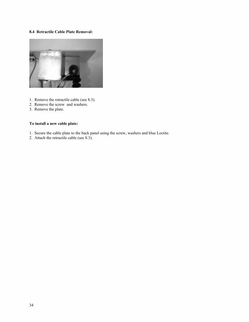
8.4 Retractile Cable Plate Removal:
1. Remove the retractile cable (see 8.3). 2. Remove the screw and washers. 3. Remove the plate. To install a new cable plate: 1. Secure the cable plate to the back panel using the screw, washers and blue Loctite. 2. Attach the retractile cable (see 8.3).
35
9. Removal Instructions - Cabinet
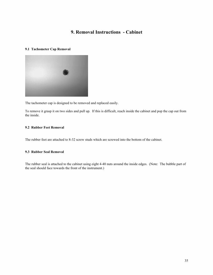
9.1 Tachometer Cap Removal
The tachometer cap is designed to be removed and replaced easily. To remove it grasp it on two sides and pull up. If this is difficult, reach inside the cabinet and pop the cap out from the inside. 9.2 Rubber Feet Removal The rubber feet are attached to 8-32 screw studs which are screwed into the bottom of the cabinet. 9.3 Rubber Seal Removal The rubber seal is attached to the cabinet using eight 4-40 nuts around the inside edges. (Note: The bubble part of the seal should face towards the front of the instrument.)

36
10. Centrifuge Quality Control
Centrifugation Speed and Time
This Quality Control should be done after each repair and/or each servicing.
10.1 Speed Quality Control To QC the centrifugation speed, follow these steps: 1. Fill the centrifuge rotor with 24 MTS Gel Cards. 2. Insert the rotor into the centrifuge. 3. Start the centrifugation. 4 . Check the speed with a tachometer. The speed of the centrifuge should be 895 rpm + 25 rpm. 5. Repeat procedures 1-4 with an empty rotor. 10.2 Centrifuge Time Quality Control To QC the centrifugation time, follow these steps: 1. Insert the rotor. 2. Close and latch the drawer. 3. Start the centrifuge and stop watch simultaneously. 4. When the centrifuge timer “times out”, turn off the stop watch. 5. Time should be 10 minutes + 10 seconds. PK No: 101-A Revision Date: 03/22/01