centrifugation chapter
DESCRIPTION
physicsTRANSCRIPT

1
Centrifugation
Introduction
A centrifuge is a device that separates particles from suspensions or even
macromolecules from solutions according to their size, shape and density by
subjecting these dispersed systems to artificially induced gravitational fields.
Centrifugation can only be used when the dispersed material is denser than the
medium in which they are dispersed. Table 6.1 lists the densities of different
biological substances that are usually separated by centrifugation.
Based on data shown in Table 6.1 one may wrongly assume that proteins and
nucleic acids would settle faster than cells and organelles. Biological
macromolecules in aqueous solution exist in an extensively hydrated form i.e. in
association with a large number of water molecules. Hence the effective densities
of these substances in solution are only slightly higher than that of water. Also,
these macromolecules are significantly smaller than cells. The substances listed in
Table 6.1 would settle at extremely low velocities under gravity and hence
separation would not be feasible. In a centrifugation process, these settling rates
are amplified using an artificially induced gravitational field.
Process Functions
There are several process functions using centrifuges in biotech separation. These
are listed below.
1. Separation (solid/liquid, solid/liquid/liquid and solid/solid/liquid
separation)
Centrifugation can be used for solid-liquid separation provided the solids are
heavier than the liquid. Centrifuge can also be used to separate a heavy phase,
and two lighter liquid phases, with one of the lighter phases being lighter than the
other. As discussed, solids can be lighter than liquid and separation is by flotation
of the dispersed solid phase.
2. Clarification- minimal solids in liquid product
Centrifuge can be used to clarify the discharged separated lighter liquid phase.
The objective is to minimize the discrete suspended solids in the light continuous
phase. Usually, only fine submicron biosolids are left uncaptured by
centrifugation and they escape with the discharged light phase.
2
3. Classification -sort by size and density
Centrifuge is used to classify solids of different sizes. One of the several possible
applications is to classify crystals of different size range, with the finer
submicron sizes leaving with the light phase and retaining only the larger sizes in
the separated heavy phase. Either of the separated solids can be the product. For
example, the larger crystals can be the product crystals while the finer crystals are
returned to the crystallizer to grow to larger crystals. Another similar application
is to classify smaller size cell debris in the light liquid phase from the heavier
products after homogenizing cells.
4. Degritting- remove oversized and foreign particles
Degritting is similar to classification where unwanted particles, larger or denser,
are rejected in the sediment, with product (smaller or less dense) overflowing in
the lighter liquid phase. Another situation is where smaller unwanted particles are
rejected in the light liquid phase, and valuable heavier solids are settled with the
heavier phase.
5. Thickening or concentration- remove liquid, concentrate solids
Centrifuge is frequently used to concentrate the solid phase by sedimentation and
compaction, removing the excess liquid phase in the overflow or centrate. This
reduces the volume of the product in downstream processing.
6. Separation and repulping - remove impurities by washing or diluting
With a concentrated suspension containing contaminants such as salts and ions, it
is diluted and washed so that the contaminants are dissolved in the wash liquid.
Subsequently, the suspension is sent for centrifugation to remove the spent wash
liquid with dissolved contaminants or finely suspended solids. Subsequently, the
product can be further concentrated by centrifugation.
The aforementioned processes can be combined to achieve several objectives
concurrently or in series.
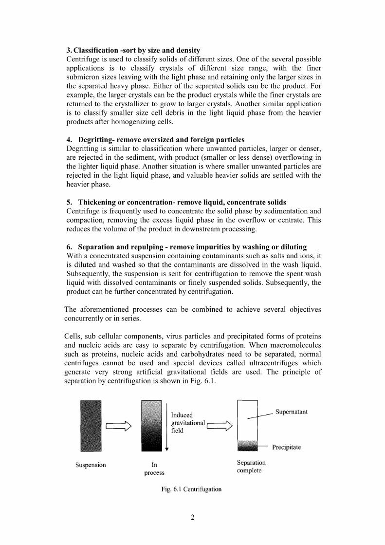
Cells, sub cellular components, virus particles and precipitated forms of proteins
and nucleic acids are easy to separate by centrifugation. When macromolecules
such as proteins, nucleic acids and carbohydrates need to be separated, normal
centrifuges cannot be used and special devices called ultracentrifuges which
generate very strong artificial gravitational fields are used. The principle of
separation by centrifugation is shown in Fig. 6.1.
3
Centrifuges are classified into two categories:
II. Laboratory centrifuges
II. Preparative centrifuges
I. Laboratory centrifuge
Laboratory centrifuges are used for small-scale separation and clarification (i.e.
removal of particles from liquids). Typical liquid volumes handled by such
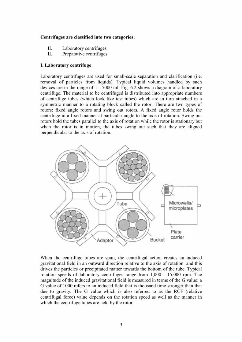
devices are in the range of 1 - 5000 ml. Fig. 6.2 shows a diagram of a laboratory
centrifuge. The material to be centrifuged is distributed into appropriate numbers
of centrifuge tubes (which look like test tubes) which are in turn attached in a
symmetric manner to a rotating block called the rotor. There are two types of
rotors: fixed angle rotors and swing out rotors. A fixed angle rotor holds the
centrifuge in a fixed manner at particular angle to the axis of rotation. Swing out
rotors hold the tubes parallel to the axis of rotation while the rotor is stationary but
when the rotor is in motion, the tubes swing out such that they are aligned
perpendicular to the axis of rotation.
When the centrifuge tubes are spun, the centrifugal action creates an induced
gravitational field in an outward direction relative to the axis of rotation and this
drives the particles or precipitated matter towards the bottom of the tube. Typical
rotation speeds of laboratory centrifuges range from 1,000 - 15,000 rpm. The
magnitude of the induced gravitational field is measured in terms of the G value: a
G value of 1000 refers to an induced field that is thousand time stronger than that
due to gravity. The G value which is also referred to as the RCF (relative
centrifugal force) value depends on the rotation speed as well as the manner in
which the centrifuge tubes are held by the rotor:

4
G = rω2/g
ω = 2πn
Substituting for ω
G = r (2πn)2/g
G = r (2*3.14*[n/60])2/9.81
G = 1.12*10-3 r n
2
G = 1.12*10-3 r (RPM)
2
Where:
r = distance from the axis of rotation (m)
ω = angular velocity (radians/s) g = acceleration due to gravity (m/s
2)
n = rotation speed, RPM
Quite clearly the G value in a centrifuge tube will depend on the location, the
highest value being at the bottom of the tube and the lowest value being at the top.
This implies that a particle will experience increasing G values while moving
towards the bottom of the centrifuge tube. In most cases the average G value that
a particle is likely to experience i.e. the numerical mean of the maximum and
minimum values is used for process calculations. Nomograms provided by
centrifuge manufacturers correlating the radial distance and rotation speed with
the G value are commonly used in the laboratory-scale calculations. Typical G
values employed in laboratory centrifuges range from 1,000 - 20,000.
A nomogram to estimate G

5
It is virtually impossible to make very exact calculations for a laboratory
centrifugation process. This is due to the fact that it usually takes a certain amount
of time after start-up for the rotation speed of the centrifuge to reach the operating
value. Similarly it takes a certain amount of time for the rotation speed to decrease
from the operating speed to zero at the end of the process. Moreover as mentioned
previously, the settling particles go through different G value zones while moving
toward the bottom of the centrifuge tube. An empirical correlation is commonly
used for estimating the complete centrifugation time:
t = k/S
Where:
k = factor of the centrifuge
S = Svedberg coefficient of the material being precipitated
t = complete sedimentation time (min)
One Svedberg unit (S) is equal to 10-13 second. A smaller k-factor results in a
faster centrifugation process. The k-factor can be calculated using the empirical
correlation shown below:
Where
rmax = radial distance from the axis to the bottom of the tube (cm)
rmin = radial distance from the axis to the top of the tube (cm)
rpmmax = maximum rotation speed (/min)
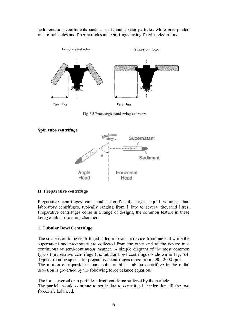
For the same rotation speed, a fixed angled rotor would have a lower k-factor on
account of the smaller difference between rmax and rmin (see Fig. 6.3). Hence the
time required for precipitating a given sample would be less with the fixed angled
rotor. This is intuitively evident from looking at Fig. 6.3 which shows that the
distance the particles have to travel for precipitation is less with the angled rotor.
However, fixed angled rotors are heavier and require much higher energy to
operate Swing out rotors are preferred for centrifuging substances with high
6
sedimentation coefficients such as cells and coarse particles while precipitated
macromolecules and finer particles are centrifuged using fixed angled rotors.
Spin tube centrifuge
II. Preparative centrifuge
Preparative centrifuges can handle significantly larger liquid volumes than
laboratory centrifuges, typically ranging from 1 litre to several thousand litres.
Preparative centrifuges come in a range of designs, the common feature in these
being a tubular rotating chamber.
1. Tubular Bowl Centrifuge
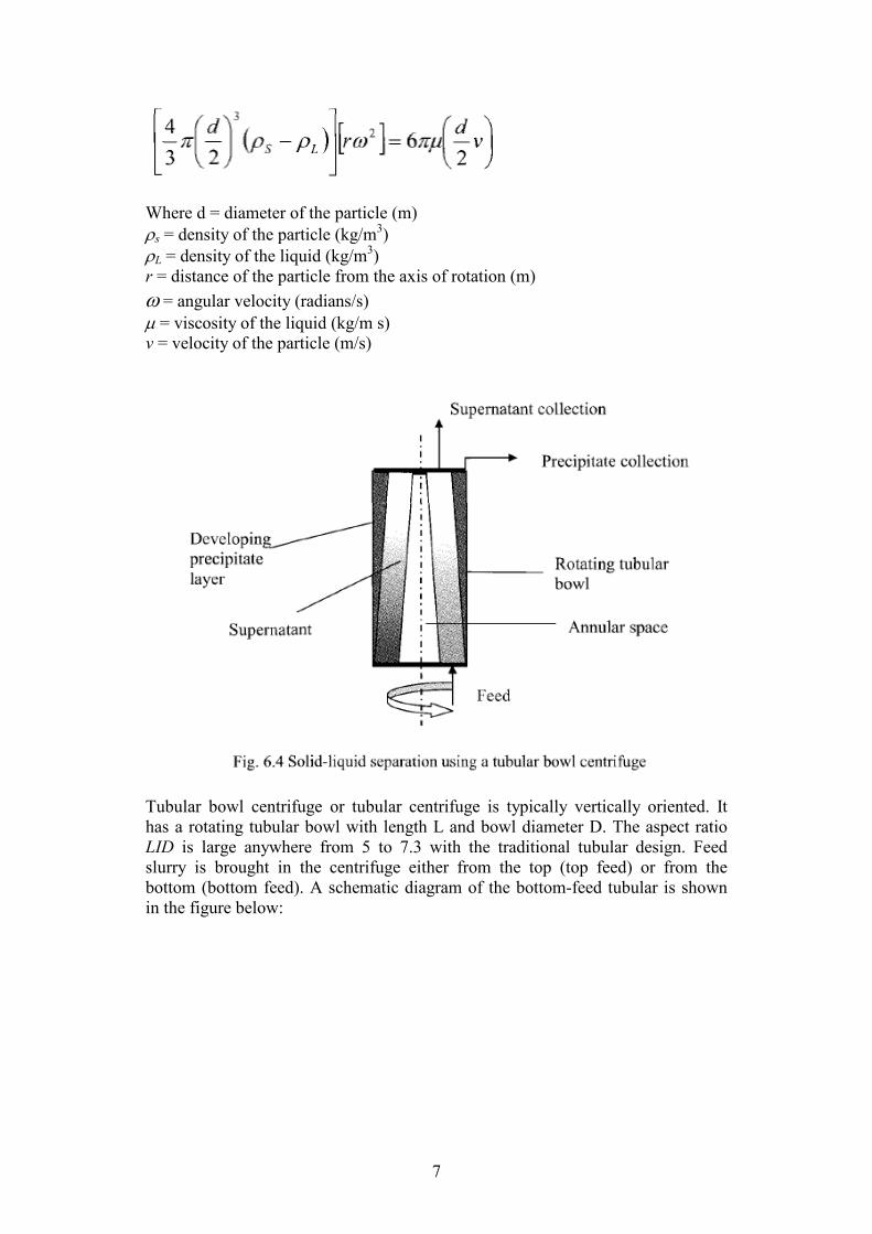
The suspension to be centrifuged is fed into such a device from one end while the
supernatant and precipitate are collected from the other end of the device in a
continuous or semi-continuous manner. A simple diagram of the most common
type of preparative centrifuge (the tubular bowl centrifuge) is shown in Fig. 6.4.
Typical rotating speeds for preparative centrifuges range from 500 - 2000 rpm.
The motion of a particle at any point within a tubular centrifuge in the radial
direction is governed by the following force balance equation:
The force exerted on a particle = frictional force suffered by the particle
The particle would continue to settle due to centrifugal acceleration till the two
forces are balanced.
7
Where d = diameter of the particle (m)
ρs = density of the particle (kg/m3)
ρL = density of the liquid (kg/m3)
r = distance of the particle from the axis of rotation (m)
ω = angular velocity (radians/s) µ = viscosity of the liquid (kg/m s)
v = velocity of the particle (m/s)
Tubular bowl centrifuge or tubular centrifuge is typically vertically oriented. It
has a rotating tubular bowl with length L and bowl diameter D. The aspect ratio
LID is large anywhere from 5 to 7.3 with the traditional tubular design. Feed
slurry is brought in the centrifuge either from the top (top feed) or from the
bottom (bottom feed). A schematic diagram of the bottom-feed tubular is shown
in the figure below:

8
The G value for the centrifuge is given by the relation:
G = 1.12*10-3 r (RPM)
2
Where, r is the radius in m
A thin annular pool is maintained between the bowl wall and the inner air core
when the centrifuge is operating at full speed. The tubular centrifuge is top
mounted (or top suspended) and top driven. Industrial-scale tubular centrifuges
have bowls 102 to 127 mm in diameter and 762 mm long. It is capable of
delivering 18,000-20,000 g. The smallest tubular, 44 mm diameter by 229 mm
long, is a laboratory model capable of developing up to 62,500 g. It is also used
for separating difficult biological solids, cells, and viruses.
The term on the left hand side of equation (6.4) is the buoyancy term while the
term on the right hand side is the Stokes drag term. In this equation we assume the
particle to be moving at constant velocity in the radial direction. Rearranging
equation (6.4):
The velocity in the radial direction can be replaced by (dr/dt). Hence:
Integrating equation (6.6), putting in appropriate limits we get:

9
Therefore:
Equation (6.7) describes the motion of a particle in the radial direction within a
centrifuge from radial location r1 to r2. In a preparative centrifuge, like the tubular
bowl centrifuge, the motion of a particle takes place in two directions: radial (due
to centrifugation) and axial (due to flow of feed). The flow of the feed within the
tubular centrifuge is annular in nature, i.e. there is an empty cylindrical shell near
the axis of rotation. This is due to the fact that the liquid within the centrifuge is
forced towards the wall of the tubular bowl due to centrifugal force. The flow of
feed within a tubular bowl centrifuge is shown in Fig 6.5: the diameter of the
tubular bowl is r, while the diameter of the annular space is ra. The flow of feed
within the centrifuge is in the axial direction (along z-axis).
The velocity of a particle along the z axis is given by:
10
Where Q = feed flow rate (m3/s)
Dividing equations (6.6) by equation (6.8) and integrating we get:
Therefore:
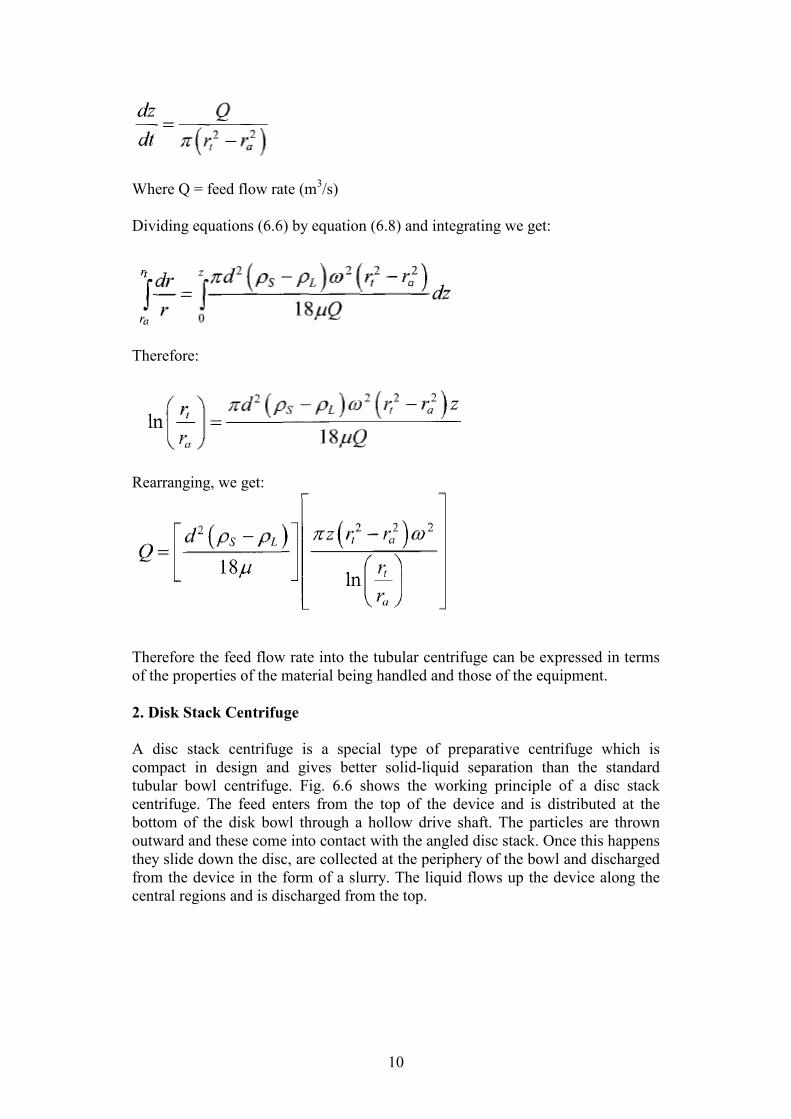
Rearranging, we get:
Therefore the feed flow rate into the tubular centrifuge can be expressed in terms
of the properties of the material being handled and those of the equipment.
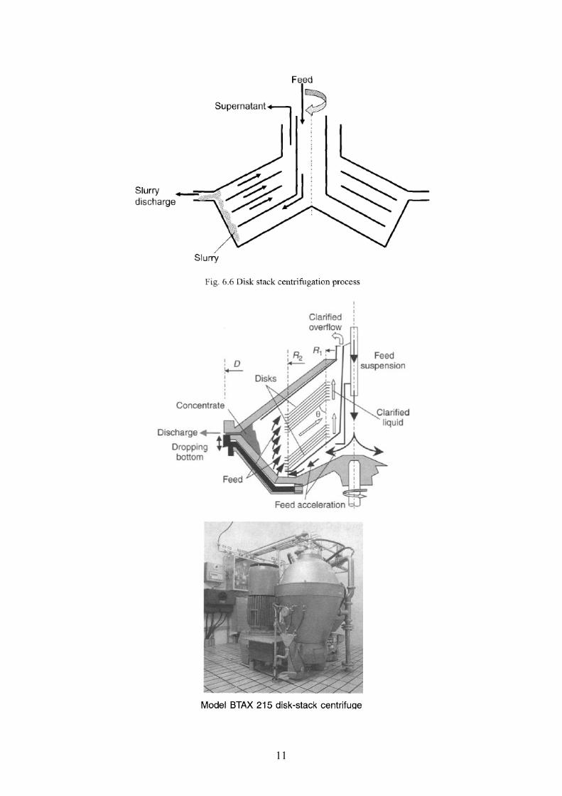
2. Disk Stack Centrifuge
A disc stack centrifuge is a special type of preparative centrifuge which is
compact in design and gives better solid-liquid separation than the standard
tubular bowl centrifuge. Fig. 6.6 shows the working principle of a disc stack
centrifuge. The feed enters from the top of the device and is distributed at the
bottom of the disk bowl through a hollow drive shaft. The particles are thrown
outward and these come into contact with the angled disc stack. Once this happens
they slide down the disc, are collected at the periphery of the bowl and discharged
from the device in the form of a slurry. The liquid flows up the device along the
central regions and is discharged from the top.
11
12
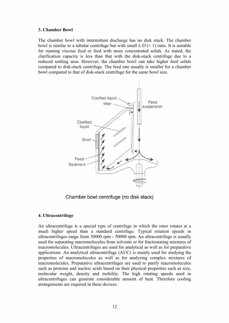
3. Chamber Bowl
The chamber bowl with intermittent discharge has no disk stack. The chamber
bowl is similar to a tubular centrifuge but with small L/D (< 1) ratio. It is suitable
for running viscous feed or feed with more concentrated solids. As stated, the
clarification capacity is less than that with the disk-stack centrifuge due to a
reduced settling area. However, the chamber bowl can take higher feed solids
compared to disk-stack centrifuge. The feed rate usually is smaller for a chamber
bowl compared to that of disk-stack centrifuge for the same bowl size.
4. Ultracentrifuge
An ultracentrifuge is a special type of centrifuge in which the rotor rotates at a
much higher speed than a standard centrifuge. Typical rotation speeds in
ultracentrifuges range from 30000 rpm - 50000 rpm. An ultracentrifuge is usually
used for separating macromolecules from solvents or for fractionating mixtures of
macromolecules. Ultracentrifuges are used for analytical as well as for preparative
applications. An analytical ultracentrifuge (AUC) is mainly used for studying the
properties of macromolecules as well as for analyzing complex mixtures of
macromolecules. Preparative ultracentrifuges are used to purify macromolecules
such as proteins and nucleic acids based on their physical properties such as size,
molecular weight, density and mobility. The high rotating speeds used in
ultracentrifuges can generate considerable amount of heat. Therefore cooling
arrangements are required in these devices.
13
An ultracentrifuge is also an angled spintube, and with a titanium rotor that
provides mechanical integrity, i.e. for high shear and yield strengths. It can go up
to 500,000-1,000,000 g for separating very small particles, particles and liquid
with a small density difference, and/or separation in a viscous liquid phase.
Theodore Svedberg invented the analytical ultracentrifuge in 1923, and won the
Nobel Prize in Chemistry in 1926 for his research on colloids and proteins using
the ultracentrifuge.
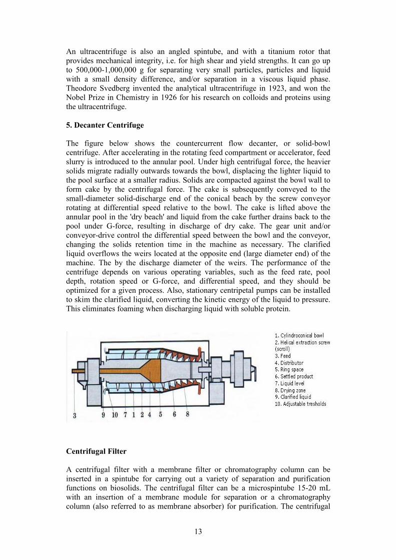
5. Decanter Centrifuge
The figure below shows the countercurrent flow decanter, or solid-bowl
centrifuge. After accelerating in the rotating feed compartment or accelerator, feed
slurry is introduced to the annular pool. Under high centrifugal force, the heavier
solids migrate radially outwards towards the bowl, displacing the lighter liquid to
the pool surface at a smaller radius. Solids are compacted against the bowl wall to
form cake by the centrifugal force. The cake is subsequently conveyed to the
small-diameter solid-discharge end of the conical beach by the screw conveyor
rotating at differential speed relative to the bowl. The cake is lifted above the
annular pool in the 'dry beach' and liquid from the cake further drains back to the
pool under G-force, resulting in discharge of dry cake. The gear unit and/or
conveyor-drive control the differential speed between the bowl and the conveyor,
changing the solids retention time in the machine as necessary. The clarified
liquid overflows the weirs located at the opposite end (large diameter end) of the
machine. The by the discharge diameter of the weirs. The performance of the
centrifuge depends on various operating variables, such as the feed rate, pool
depth, rotation speed or G-force, and differential speed, and they should be
optimized for a given process. Also, stationary centripetal pumps can be installed
to skim the clarified liquid, converting the kinetic energy of the liquid to pressure.
This eliminates foaming when discharging liquid with soluble protein.
Centrifugal Filter
A centrifugal filter with a membrane filter or chromatography column can be
inserted in a spintube for carrying out a variety of separation and purification
functions on biosolids. The centrifugal filter can be a microspintube 15-20 mL
with an insertion of a membrane module for separation or a chromatography
column (also referred to as membrane absorber) for purification. The centrifugal
14
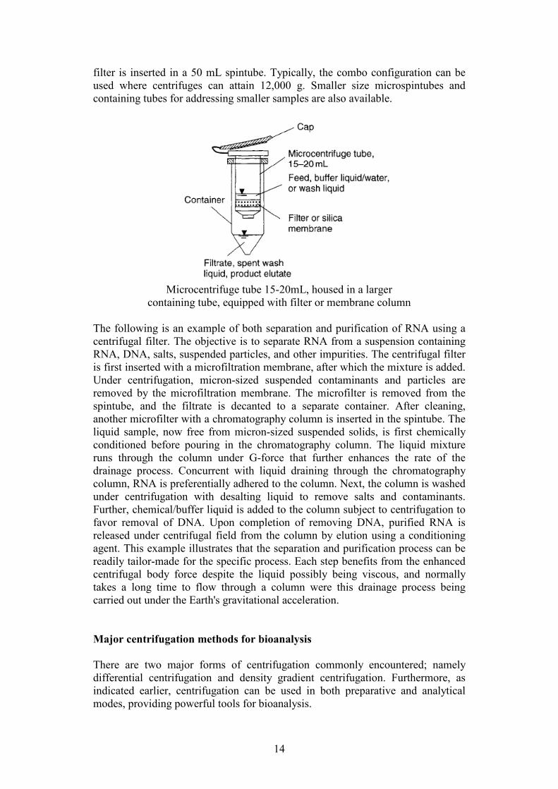
filter is inserted in a 50 mL spintube. Typically, the combo configuration can be
used where centrifuges can attain 12,000 g. Smaller size microspintubes and
containing tubes for addressing smaller samples are also available.
Microcentrifuge tube 15-20mL, housed in a larger
containing tube, equipped with filter or membrane column
The following is an example of both separation and purification of RNA using a
centrifugal filter. The objective is to separate RNA from a suspension containing
RNA, DNA, salts, suspended particles, and other impurities. The centrifugal filter
is first inserted with a microfiltration membrane, after which the mixture is added.
Under centrifugation, micron-sized suspended contaminants and particles are
removed by the microfiltration membrane. The microfilter is removed from the
spintube, and the filtrate is decanted to a separate container. After cleaning,
another microfilter with a chromatography column is inserted in the spintube. The
liquid sample, now free from micron-sized suspended solids, is first chemically
conditioned before pouring in the chromatography column. The liquid mixture
runs through the column under G-force that further enhances the rate of the
drainage process. Concurrent with liquid draining through the chromatography
column, RNA is preferentially adhered to the column. Next, the column is washed
under centrifugation with desalting liquid to remove salts and contaminants.
Further, chemical/buffer liquid is added to the column subject to centrifugation to
favor removal of DNA. Upon completion of removing DNA, purified RNA is
released under centrifugal field from the column by elution using a conditioning
agent. This example illustrates that the separation and purification process can be
readily tailor-made for the specific process. Each step benefits from the enhanced
centrifugal body force despite the liquid possibly being viscous, and normally
takes a long time to flow through a column were this drainage process being
carried out under the Earth's gravitational acceleration.
Major centrifugation methods for bioanalysis
There are two major forms of centrifugation commonly encountered; namely
differential centrifugation and density gradient centrifugation. Furthermore, as
indicated earlier, centrifugation can be used in both preparative and analytical
modes, providing powerful tools for bioanalysis.
15
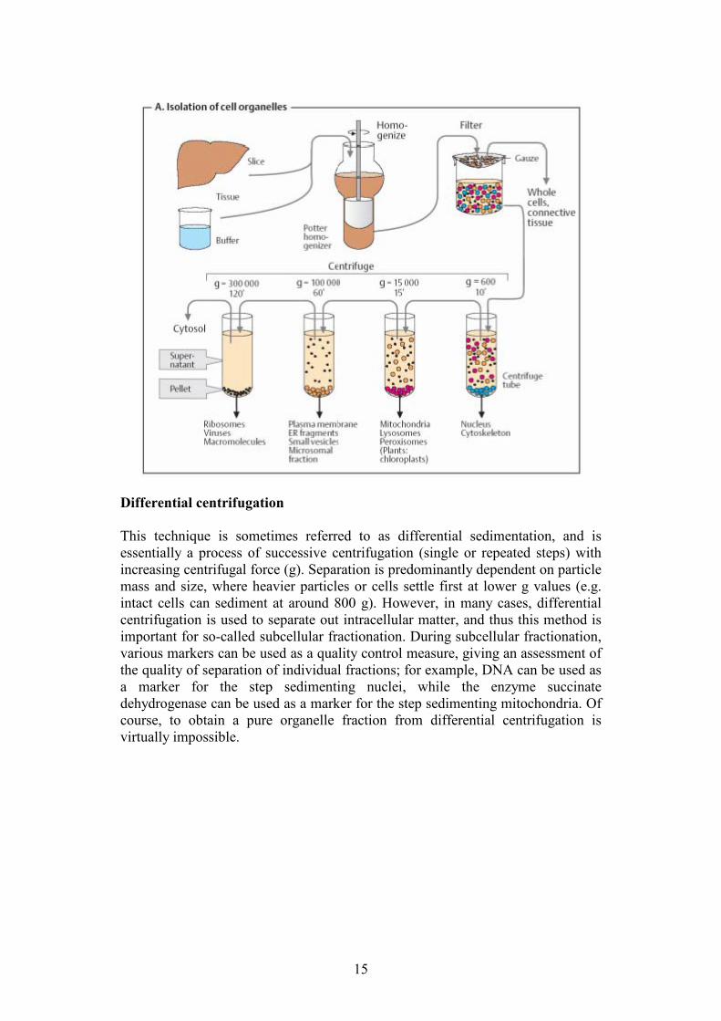
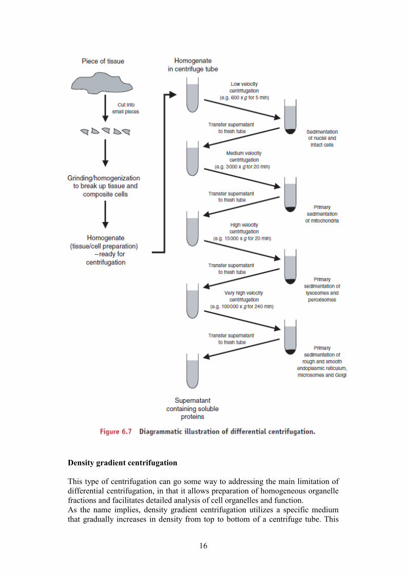
Differential centrifugation
This technique is sometimes referred to as differential sedimentation, and is
essentially a process of successive centrifugation (single or repeated steps) with
increasing centrifugal force (g). Separation is predominantly dependent on particle
mass and size, where heavier particles or cells settle first at lower g values (e.g.
intact cells can sediment at around 800 g). However, in many cases, differential
centrifugation is used to separate out intracellular matter, and thus this method is
important for so-called subcellular fractionation. During subcellular fractionation,
various markers can be used as a quality control measure, giving an assessment of
the quality of separation of individual fractions; for example, DNA can be used as
a marker for the step sedimenting nuclei, while the enzyme succinate
dehydrogenase can be used as a marker for the step sedimenting mitochondria. Of
course, to obtain a pure organelle fraction from differential centrifugation is
virtually impossible.
16
Density gradient centrifugation
This type of centrifugation can go some way to addressing the main limitation of
differential centrifugation, in that it allows preparation of homogeneous organelle
fractions and facilitates detailed analysis of cell organelles and function.
As the name implies, density gradient centrifugation utilizes a specific medium
that gradually increases in density from top to bottom of a centrifuge tube. This

17
means that under centrifugal force, particles will move through the medium and
density gradient and stop (are suspended) at a point in which the density of the
particle equals the density of the surrounding medium. The medium used depends
on the desired outcome, with four general categories: (i) alkali metal salts (e.g.
caesium chloride); (ii) neutral water-soluble molecules (e.g. sucrose); (iii)
hydrophilic macromolecules (e.g. dextran); and (iv) synthetic molecules (e.g.
methyl glucamine salt of tri-iodobenzoic acid). The density gradient can be
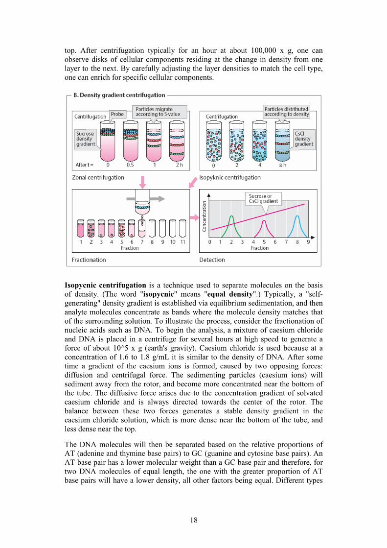
established in the tube either before (zonal) or during (isopycnic) centrifugation.
Both zonal and isopycnic centrifugation are illustrated in the figure below.
For zonal density gradient centrifugation there are a number of media that can be
used, however the most common of these is sucrose; whereas the most common
medium for isopycnic density gradient centrifugation is caesium chloride (CsCl).
Equilibrium sedimentation uses a gradient of a solution such as caesium
chloride or sucrose to separate particles based on their individual densities
(mass/volume). It is used as a purifying process for differential centrifugation. A
solution is prepared with the densest portion of the gradient at the bottom.
Particles to be separated are then added to the gradient and centrifuged. Each
particle proceeds (either up or down) until it reaches an environment of
comparable density. Such a density gradient may be continuous or prepared in a
stepped manner. For instance, when using sucrose to prepare density gradients,
one can carefully float a solution of 40% sucrose onto a layer of 45% sucrose and
add further less dense layers above. The homogenate, prepared in a dilute buffer
and centrifuged briefly to remove tissue and unbroken cells, is then layered on
18
top. After centrifugation typically for an hour at about 100,000 x g, one can
observe disks of cellular components residing at the change in density from one
layer to the next. By carefully adjusting the layer densities to match the cell type,
one can enrich for specific cellular components.
Isopycnic centrifugation is a technique used to separate molecules on the basis
of density. (The word "isopycnic" means "equal density".) Typically, a "self-
generating" density gradient is established via equilibrium sedimentation, and then
analyte molecules concentrate as bands where the molecule density matches that
of the surrounding solution. To illustrate the process, consider the fractionation of
nucleic acids such as DNA. To begin the analysis, a mixture of caesium chloride
and DNA is placed in a centrifuge for several hours at high speed to generate a
force of about 10^5 x g (earth's gravity). Caesium chloride is used because at a
concentration of 1.6 to 1.8 g/mL it is similar to the density of DNA. After some
time a gradient of the caesium ions is formed, caused by two opposing forces:
diffusion and centrifugal force. The sedimenting particles (caesium ions) will
sediment away from the rotor, and become more concentrated near the bottom of
the tube. The diffusive force arises due to the concentration gradient of solvated
caesium chloride and is always directed towards the center of the rotor. The
balance between these two forces generates a stable density gradient in the
caesium chloride solution, which is more dense near the bottom of the tube, and
less dense near the top.
The DNA molecules will then be separated based on the relative proportions of
AT (adenine and thymine base pairs) to GC (guanine and cytosine base pairs). An
AT base pair has a lower molecular weight than a GC base pair and therefore, for
two DNA molecules of equal length, the one with the greater proportion of AT
base pairs will have a lower density, all other factors being equal. Different types

19
of nucleic acids will also be separated into bands, e.g. RNA is denser than
supercoiled plasmid DNA, which is denser than linear chromosomal DNA.
Caesium chloride allows for greater precision in separating particles of similar
density. In fact, with a caesium chloride gradient, DNA particles that have
incorporated heavy isotopes (13C or
15N for example) can be separated from DNA
particles without heavy isotopes.
Protein Yield
For a soluble protein expressed from extracellular process, one important measure
of the separation performance of the centrifuge is the protein yield Y. Yield is
defined as the ratio of the amount (e.g. kg/min or gm/min) of protein recovered in
the liquid product to the amount (kg/min or g/min) of protein in the feed to the
centrifuge. A complete recovery of protein without loss is 100%. Usually the yield
should be very high before the separation process can be considered viable. A
90% or higher yield is not untypical. The specific yield depends on how difficult
the separation is.
For continuous-feed centrifuge, the volumetric rate (L/m) and protein
concentration of both feed and centrate need to be measured respectively for
calculation of yield. For batch-feed centrifuge, the volume and protein
concentration of both feed and supernatant (i.e. centrate) should be measured
respectively for the yield calculation. It is evident that liquid loss in the
concentrate or cake affects yield as the protein is dissolved in liquid, therefore the
amount of liquid in the concentrate should be minimized.