mt/jig - trend direct uk · mt/jig-1-dear customer thank you for purchasing this trend product, we...
TRANSCRIPT

MT/JIG
International Patent No.:PCT/GB02/00253
MANU-M&T v2.3 16/11/10 14:38 Page 27

MT/JIG
-1-
Dear Customer
Thank you for purchasing this Trend product, wehope you enjoy many years of creative andproductive use.
Please remember to return your guarantee cardwithin 28 days of purchase.
☎ If you require further safety advice,technical information or spare parts,please call our Technical Supportdepartment or visit www.trend-uk.com
TECHNICAL DATA
Material thickness min. 12mmmax. 47mm
Tenon thickness min. 4.8mmmax. 16mm
Using Vertical Guide:Tenon width max. 90mm+
Mortise length max. 90mm++
Angle tilt compound -10° to 45°Weight 6kg+ on end of 100mm wide material++ unlimited if vertical guide is removed andwood is repositioned.
The following symbols are used throughout thismanual:
Denotes risk of personal injury, loss oflife or damage to the tool in case of non-observance of the instructions in thismanual.
Refer to the instruction manual ofyour power tool.
This unit must not be put into service until it hasbeen established that the power tool to beconnected to this unit is in compliance with2006/42/EC (identified by the CE marking on the power tool).
INTENDED USEThis jig is intended to be used with aplunge router fitted with a suitable cutterand guide bush to cut mortise and tenonsin natural wood.
CONTENTSTECHNICAL DATA _____________________1SAFETY____________________________2-3ITEMS ENCLOSED ____________________4DESCRIPTION OF PARTS_______________5ACCESSORIES _______________________ 6ASSEMBLY & ADJUSTMENT ____________7– Assembly of the Top Plate ______________8– Cutter & Guide Bush Selection __________9– Fitting of Guide Bushes _______________10– Fitting the Optional Dust Extraction Kit ___11TIMBER PREPARATION & MARKING OUT– Marking out the tenon ________________12OPERATION– Set Timber Height ___________________13– Set Tenon Length____________________14– Set Centre Line _____________________15– Routing Procedure ___________________16– Side Angled Tenon___________________17– Front Angled Tenon __________________18– Setting Up for the Mortise _____________19– Cutting the Mortise___________________20– Square Mortise & Tenons______________21– Dowelling _______________________22-23MAINTENANCE ______________________23ENVIROMENTAL PROTECTION &GUARANTEE ________________________23SPARE PARTS– Spare Parts List _____________________24– Spare Parts Diagram _________________25
Max
1-7
/8"
(47m
m)
Up to 4" (100mm) unlimitedif wood is repositioned
Max 3-1/2” (90mm) tenon lengthusing vertical guide
5/8"(16mm)
3/16
" (4
.75m
m)
Min1/2"
(12mm)
Min/Max Mortise & Tenon Sizes
MANU-M&T v2.3 16/11/10 14:38 Page 1

MT/JIG
-2-
SAFETYWARNING:
Observe the safety regulations in theinstruction manual of the power tool to beused. Please read the followinginstructions carefully. Failure to do socould lead to serious injury. When usingelectric tools, basic safety precautions,including the following should always befollowed to reduce the risk of fire, electricshock and personal injury. Also observeany applicable additional safety rules.Read the following safety instructionsbefore attempting to operate this product.
PLEASE KEEP THESEINSTRUCTIONS IN A SAFE PLACE.
The attention of UK users is drawn to TheProvision and Use of Work EquipmentRegulations 1998, and any subsequentamendments.
Users should also read the HSE/HSCSafe Use of Woodworking MachineryApproved Code of Practice and GuidanceDocument and any amendments.
Users must be competent withwoodworking equipment before using ourproducts.
IMPORTANT NOTE:
Residual Risk. Although the safetyinstructions and operating manuals forour tools contain extensive instructions onsafe working with power tools, everypower tool involves a certain residual riskwhich cannot be completely excluded bysafety mechanisms. Power tools musttherefore always be operated withcaution!
General1. Disconnect power tool and attachment
from power supply when not in use,before servicing, when makingadjustments and when changingaccessories such as cutters. Ensureswitch is in “off” position. Alwaysensure cutter has stopped rotating.
2. Always mount the power tool,accessory or attachment in conformitywith the instructions. Only useattachment and accessories specifiedin the power tool manual. The tool orattachment should not be modified orused for any application other thanthat for which it was designed. Do notforce tool.
3. Keep children and visitors away. Donot let children or visitors touch thetool, accessory or attachment. Keepchildren and visitors away from workarea. Make the workshop child proofwith padlock and master switch.
4. Dress properly. Do not wear looseclothing or jewellry, they can becaught in moving parts. Rubber glovesand non-skid footwear is
recommended when workingoutdoors. Wear protective haircovering to contain long hair.
5. Consider working environment. Do notuse the product in the rain or in adamp environment. Keep work areawell lit. Do not use power tools neargasoline or flammable liquids. Keepworkshop at a comfortabletemperature so your hands are notcold. Connect machines that are usedin the open via a residual currentdevice (RCD) with an actuationcurrent of 30 mA maximum. Use onlyextension cables that are approved foroutdoor use.
6. The accessory or attachment must bekept level and stable at all times.
7. Keep work area clean. Clutteredworkshops and benches can causeinjuries. Ensure there is sufficientroom to work safely.
8. Secure idle tools. When not in use,tools should be stored in a dry andhigh or locked up place, out of reachof children.
9. For best control and safety use bothhands on the power tool andattachment. Keep both hands awayfrom cutting area. Always wait for thespindle and cutter to stop rotatingbefore making any adjustments.
10.Always keep guards in place and ingood working order.
11.Remove any nails, staples and othermetal parts from the workpiece.
12.Maintain tools and cutters with care.Keep cutters sharp and clean forbetter and safer performance. Do notuse damaged cutters. Followinstructions for lubricating andchanging accessories. Keep handlesdry, clean and free from oil andgrease.
13.Maintain accessories. Do not usedamaged accessories. Only useaccessories recommended by themanufacturer.
14.Check damaged parts. Beforeoperation inspect the attachment, thepower tool, the cable, extension cableand the plug carefully for signs ofdamage. Check for alignment ofmoving parts, binding, breakage,mounting and any other conditionsthat may effect its operation. Have anydamage repaired by an AuthorisedService Agent before using the tool oraccessory. Protect tools from impactand shock.
15.Do not use tool if switch does not turnit on or off. Have defective switchesreplaced by an Authorised ServiceAgent
16.Don't over reach. Keep proper footing
and balance at all times. Do not useawkward or uncomfortable handpositions.
17.Don’t abuse the cable. Never carrypower tool or accessory by cord orpull it to disconnect from the socket.Keep cord from heat, oil and sharpedges. Always trail the power cordaway from the work area.
18.Connect dust extraction equipment.If devices are provided for theconnection of dust extraction andcollection facilities, ensure these areconnected and properly used.
19.Check all fixing and fastening nuts,bolts and screws on power tool,attachment and cutting tools beforeuse to ensure they are tight andsecure. Periodically check whenmachining over long periods.
20.Stay alert. Watch what you are doing.Use common sense. Do not operatetools when you are tired, under theinfluence of drugs or alcohol.
21.Personal Protective Equipment (PPE)for eye, ear and respiratory protectionmust be worn. All PPE must meetcurrent UK and EU legislation.
22.Do not leave tools runningunattended. Do not leave tool until itcomes to a complete stop.
23.Always clamp workpiece beingmachined securely.
24.Only use cutting tools forwoodworking that meet EN847-1/2safety standards, and anysubsequent amendments.
25.Vibration levels. Hand held powertools produce different vibrationlevels. You should always refer to thespecifications and relevant Health &Safety Guide.
Routing Safety
1. Read and understand instructionssupplied with power tool, attachmentand cutter.
2. Keep hands, hair and clothing clear ofthe cutter.
3. Remove adjusting keys andspanners. Check to see that keys andadjusting spanners are removed fromthe router tool, cutter and attachmentbefore turning router on. Make surecutter can rotate freely.
4. Noise. Take appropriate measures forthe protection of hearing if the soundpressure of 85dB(A) is exceeded.Routing sound pressure may exceed85dB(A), so ear protection must beworn.
5. Eye protection. Always wear eyeprotection in the form of safetygoggles, spectacles or visors toprotect the eyes.
MANU-M&T v2.3 16/11/10 14:38 Page 2

MT/JIG
-3-
6. Respiratory protection. Wear a face ordust mask, or powered respirator.Dust masks/filters should be changedregularly.
7. Do not switch router on with the cuttertouching the workpiece. At the end ofthe cut, release the router plunge andallow spindle to stop rotating. Neveruse the spindle lock as a brake
8. The direction of routing must alwaysbe opposite to the cutter's direction ofrotation. Do not back-cut or climb-cut.
9. Check before cutting that there are noobstructions in the path of the router.Ensure there are no obstaclesbeneath workpiece when cutting fullthickness, and that a sacrificial worksurface is used.
Router Cutter Safety
1. Cutting tools are sharp. Care shouldbe taken when handling them. Do notdrop cutters or knock them againsthard objects. Handle very smalldiameter cutters with extra care.Always return cutter to its packagingafter use.
2. Always use cutters with a shankdiameter corresponding to the size ofthe collet installed in your tool.
3. The maximum speed (n.max) markedon the tool, or in instructions or onpackaging shall not be exceeded.Where stated the speed range shallbe adhered to. Recommended speedsare shown in the Trend RoutingCatalogue and/or website.
4. Always use router cutters in a router.Drill and boring bits must not be usedin a router. Router cutters must onlybe used for the material cuttingapplication for which they aredesigned. Do not use on metal ormasonry.
5. Never use cutters with a diameterexceeding the maximum diameterindicated in the technical data of thepowertool or attachment used.
6. Before each use check that the cuttingtool is sharp and free from damage.Do not use the cutting tool if it is dull,broken or cracked or if in any otherdamage is noticeable or suspected.
7. Cutters should be kept clean. Resinbuild up should be removed at regularintervals with Resin Cleaner®. Theuse of a PTFE dry lubricant willreduce resin build up. Do not usePTFE spray on plastic parts.
8. When using stacked tooling (multi-blade, block and groover etc.) on aspindle arbor, ensure that the cuttingedges are staggered to each other toreduce the cutting impact.
9. Cutter shanks should be inserted intothe collet all the way to the line
indicated on the shank. This ensuresthat at least 3⁄4 of the shank length isheld in the collet. Ensure clampingsurfaces are cleaned to remove dirt,grease, oil and water.
10.Observe the correct assembly andfitting instructions in the routerinstruction manual for fitting the collet,nut and cutter.
11.Tool and tool bodies shall be clampedin such a way that they will notbecome loose during operation. Careshall be taken when mounting cuttingtools to ensure that the clamping is bythe shank of the cutting tool and thatthe cutting edges are not in contactwith each other or with the clampingelements.
12. It is advisable to periodically checkthe collet and collet nut. A damaged,worn or distorted collet and nut cancause vibration and shank damage.Do not over-tighten the collet nut
13.Do not take deep cuts in one pass;take several shallow or light passes toreduce the side load applied to thecutter and router. Too deep a cut inone pass can stall the router.
15. In case of excessive vibrations whilstusing the router stop immediately andhave the eccentricity of the router,router cutter and clamping systemchecked by competent personnel
15.All fastening screws and nuts shouldbe tightened using the appropriatespanner or key and to the torquevalue provided by the manufacturer.
16. Extension of the spanner ortightening using hammer blows shallnot be permitted.
17.Clamping screws shall be tightenedaccording to instructions provided bythe manufacture. Where instructionsare not provided, clamping screwsshall be tightened in sequence fromthe centre outwards.
Using Routers In A Fixed Position
1. Attention should be made to theHSE’s Safe Use of Vertical SpindleMoulding Machines Information SheetNo.18 and any revisions.
2. After work, release the router plungeto protect the cutter.
3. Always use a push-stick or push-blockwhen making any cut less than300mm in length or when feeding thelast 300mm of the cut.
4. The opening around the cutter shouldbe reduced to a minimum usingsuitably sized insert rings in the tableand closing the back fence cheeks orfitting a false fence on the back fence.
5. Whenever possible use a work
holding device or jig to securecomponent being machined. Ensureany attachment is securely fitted to theworkbench, with table surface atapproximately hip height.
6. Use a No-Volt Release Switch. Ensureit is fixed securely, easily accessibleand used correctly.
7. In router table (inverted) mode, standto the front right of the table. Thecutter will rotate anti-clockwise whenviewed from top so the feed directionis from the right (against the rotation ofthe cutter). In overhead mode, standto the front left of the machine tableand the feed direction is from the left.
8. Do not reach underneath table or putyour hands or fingers at any time inthe cutting path while tool is connectedto a power supply.
9. Never thickness timber between theback of the cutter and the backfence.
Useful Advice When Routing
1. Judge your feed rate by the sound ofthe motor. Feed the router at aconstant feed rate. Too slow a feedrate will result in burning.
2. Trial cuts should be made on wastematerial before starting any project.
3. When using some attachments e.g. arouter table or dovetail jig, a fineheight adjuster is recommended.
4. When using a template guide bush,ensure there is sufficient clearancebetween cutter tip and inside edge ofbush and that it cannot come intocontact with collet and nut. Ensurecutter and guide bush are concentric.
Router Cutter Repair/Maintenance
1. Repair of tools is only allowed inaccordance with the manufacturersinstructions.
3. The design of composite (tipped) toolsshall not be changed in process ofrepair. Composite tools shall berepaired by a competent person i.e. aperson of training and experience, whohas knowledge of the designrequirements and understands thelevels of safety to be achieved.
4. Repair shall therefore include, e.g. theuse of spare parts which are inaccordance with the specification ofthe original parts provided by themanufacturer.
5. Tolerances which ensure correctclamping shall be maintained.
6. Care shall be taken that regrinding ofthe cutting edge will not causeweakening of the body and theconnection of the cutting edge to thebody.
Version 7.1 06/2006
MANU-M&T v2.3 16/11/10 14:38 Page 3
x1
x1
x1
x1
x1
x2 x1
x4
x2
x2x4
x1
x1
x5
L
5/8"1/2"
3/8"5/16"
1/4"
15.9mm
12.7mm
9.5mm
7.9mm
6.4mmTENON WIDTH
5/8" 15.9
1/2" 12.7
3/8" 9.5
5/16" 7.9
1/4" 6.4
R5/8" 1
5.9
1/2" 12.7
3/8" 9.5
5/16" 7.9
1/4" 6.4
Align with tenon end
& position templates
MORTIS
E & TENON JIG
SET-UP B
AR
1. Set Timber H
eight
2. Set C
entre Line
3. Set Tenon Length
GB222
GB254
GB286
GB302
GB318
C026
C022
C015
C012
C008
TENON BUSHMORTISE CUTTER
GUIDE BUSH & CUTTER SELECTIONNOTE
For tenon use cutter C
O26
For mortis
e use 2-1/8" collar
WP-MT/02/UK
x4
x1
x1
x1 x1
MT/JIG
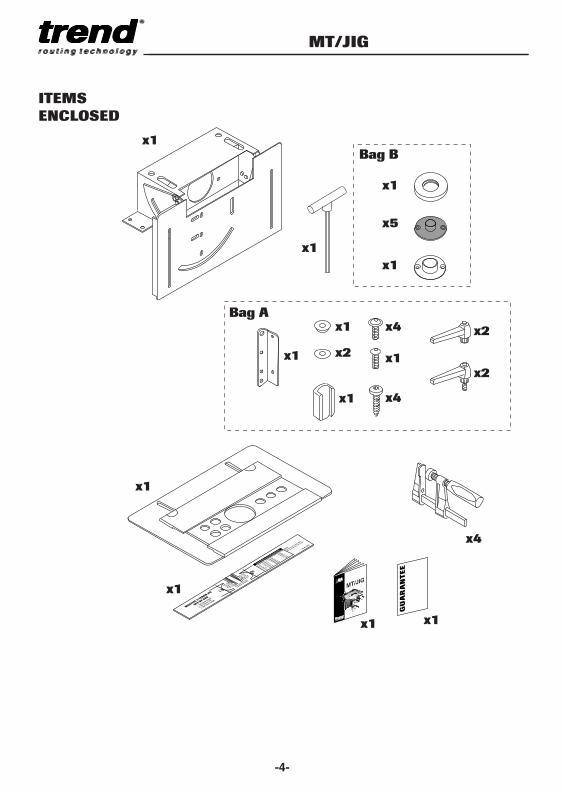
Bag B
Bag A
MT/JIG
-4-
ITEMS
ENCLOSED
MANU-M&T v2.3 16/11/10 14:38 Page 4

DESCRIPTION
OF PARTS
A Female adjustable lever
B Top plate assembly
C Template clamp (back)
D Long template
E Set-up bar
F Template clamp (front)
G Male adjustable lever
H F clamp handle
I Short template
J Main body
K Tilting back plate
L Vertical guide
M Flanged machine screw
N F clamp bar
O CollarImperial 25.4mm - 54mmMetric 30mm - 54mm
P Plastic guide bushes
Q Metal guide bush
R F clamp cap
MT/JIG
-5-
MANU-M&T v2.3 16/11/10 14:38 Page 5

ACCESSORIESSuitable router cuttersAlthough standard router cutters can be used having the appropriate diameter, a set offive long reach straight cutters with 1⁄4" or 8mm shanks are available. Spiral bits can beused for an improved finish.
Ref. SET/MT1X1/4TC or Metric Euro jig requires cutter set SET/MT1X8MMTC Ref. SET/MT2X8MMTC.
These cutters are also available separately.
Optional Extraction Dust KitFor dust-free working, this kit allows connection to a 39mm or 58mm hose. The dustshield is only used when routing 90° tenons.Ref. MT/DUSTKIT
Metal Guide BushesThese can be purchased to replace the plastic versions supplied with the jig or foralternative sizes of tenons.
MT/JIG
-6-
D
x4 x4 x4 x2
Dia. Ref. Set Ref.
6.3mm (1⁄4”) C0087.9mm (5⁄16”) C0129.5mm (3⁄8”) C015 SET/MT112.7mm (1⁄2”) C02215.8mm (5⁄8”) C026
Other cutters for alternative Tenon
4.8mm (3⁄16”) C00311.1mm (7⁄16”) C018A14.3mm (9⁄16”) C024
Dia. Ref. Set Ref.
6mm C005A8mm C012A10mm C016B SET/MT212mm C17116mm C025B
Other cutters for alternative Tenon
14mm C023B
IMPERIAL JIG
Dia. Ref.
15.9mm (5⁄8”) GB15922.2mm (7⁄8”) GB22223.8mm (15⁄16”) GB23827mm (1 1⁄16”) GB2728.6mm (1 3⁄8”) GB28630.2mm (1 3⁄16”) GB30231.8mm (1 1⁄4”) GB31833.3mm (1 5⁄16”) GB333
METRIC JIG
Dia. Ref.
15.9mm GB15922mm GB2226mm GB2628mm GB2830mm GB3032mm GB32
Dust shieldDust spoutAdaptor
MANU-M&T v2.3 16/11/10 14:38 Page 6

ASSEMBLY &
ADJUSTMENT
x4
x4
� Secure the tiltingback plate in its45° position with the two hex screws.
� Position the main body on the edge of the workbench or workboard and drill four 3mm/1⁄8" holes 15mm deep.
� Secure the jig with the 4 self-tapping screws with a No.2 Pozi screw driver.
� Fit the three F clamps and vertical guide as shown. Noting that the longer hex screw withouta flange is used inconjunction with the pivot bush.
� Return the tilting back plate to the 0° position and lock.
Pivot bush
MT/JIG
-7-
�
�
�
�
MANU-M&T v2.3 16/11/10 14:38 Page 7

MT/JIG
-8-
Assembly of
the Top Plate
10mm� Remove the
transit nuts with a 10mm spanner and discard.
� Fit the two female adjustable levers.If fitting the optional dust extraction kit referto page 11.
� Turn the top plateover so that it’s facing up and secure the top plate with the two male adjustable levers and washers.
To adjust tightness of the
templates undo the nuts on
the underside of the top
plate. Holding the plate
clamping piece by the
thumb notches, gently tap
the plate to reset. Tighten
the nuts to secure.
Hold Hold
MANU-M&T v2.3 16/11/10 14:38 Page 8

Cutter &
Guide Bush
Selection
Imperial Jig - UK
� Calculate an appropriate tenon width ‘X’ for the timber width ‘W’ e.g. X = 1⁄4” andchoose the nearest appropriate tenonwidth from the chart below.
� For the tenon choose the appropriate guide bush diameter ‘D’ from the chart below for the tenon width, e.g. D = 11⁄4". Tenon cutter will always be Ref. C026.
� For the mortise choose the cutter to suit the tenon width ‘X’ e.g. C008. Guide bush will always be the metal GB254 fitted with the collar.
Guide BushImperial Diameter Guide Bush Cutter Guide Bush Cutter
X D Ref. Ref. Dia (Ref.) Ref.
1⁄4” (6.3mm) 11⁄4” (31.8mm) GB318 Use Use C0085⁄16” (7.9mm) 13⁄16” (30.2mm) GB302 C026 1”(GB254) C0123⁄8” (9.5mm) 11⁄8” (28.6mm) GB286 for plus C0151⁄2” (12.7mm) 1” (25.4mm) GB254 all collar C0225⁄8” (15.8mm) 7⁄8” (22.2mm) GB222 cuts. C026
Other sizes possible.*
3⁄16” (4.8mm) 15⁄16” (33.3mm) GB333 C0037⁄16” (11.1mm) 11⁄16” (27mm) GB27 C018A9⁄16” (14.3mm) 15⁄16” (23.8mm) GB238 C024
*Guide bushes not included with jig.
TENON MORTISETENONWIDTH
MT/JIG
-9-
WX
w3
D
Ref. GB/COLL/25454
Ref. GB/254 X
ExampleTenon Width (X) = Timber width of (W) 3⁄4” (19mm) = 1⁄4” (6.3mm)
3
X =
1
�
�
�
MANU-M&T v2.3 16/11/10 14:38 Page 9

Fitting the Guide
Bushes
TREND T3, T5, T5MK2, T9
AEG OF450S, 500S, OFE710
ATLAS COPCO OFS50, 720, OFSE850, 1000
AXMINSTER AW635R
BLACK&DECKER SR100, BD780(E),
KW779, 780(E), 800(E), 850ET
CHAMPION CPR850
CHALLENGE 1020W
CHALLENGE EXTREME MR5757
CLARKE CR1
DEWALT DW613, 614, 615
DRAPER R850V
EINHELL EOF850SP
ELU MOF96(E) Mk2, MOF69
FERM FBF-6E, 8E
FELISATTI R346EC
HOLZHER 2335, 2336, 2356
JCBP PR, 1217
KANGO R8550S
KRESS FM6955
NUTOOL NPT850, 102
PERFORMANCE POWER 1020W
PERLES OF808(E), OF2-808(E)
POWER DEVIL PDW5026, 5027, 5037PRA
POWER MASTER 710W
SILVERLINE SL762
STAYER PR50
VIRUTEX FR77C, 78C, 66F
WICKES 900W, 1200W
ATLAS COPCO OFSE2000
B&D BD780(E), KW779, 780(E), 800(E), SR100
BOSCH POF52A, 400A, 500A, 600ACE,
800ACE, GOF900A, 900ACE, 1300ACE,
1600A, 1700ACE
CASALS FT750,1000E, 2000VCE
DEWALT DW620, 621, 624, 625EK, 629
DRAPER R1900V
ELU OF97E, 131, 177(E) MK2
FESTO OF900E, 1000E, 1010EBC, 2000E
FREUD FT1000(E), 2000(E)
FELISATTI TP246(E)
HITACHI FM8, ZK2008, M8, 8V, 12(V), M12SA
MAFELL LO50E
MAKITA RP0910, 1110C, 3600B, 3620,
3612BR, 3612(C)
MAX PRO MIR-KW02-12
METABO OF528, 1028, 1612, OFE1229, 1812
PEUGEOT DEF570E, DF55E
RYOBI R150, 151, 155, 500, 502, 600, 600N,
RE120, RE155K, RE600(N), RE601,
SKIL 1835U, 1875U1
SPARKY X52E
WADKIN R500
MT/JIG
-10-
Guide BushMetric Diameter Guide Bush Cutter Guide Bush Cutter
X D Ref. Ref. Dia (Ref.) Ref.
6mm 32mm GB32 Use Use C005A8mm 30mm GB30 C025B 30mm (GB30) C012A10mm 28mm GB28 for plus collar C016B12mm 26mm GB26 all Ref. C17116mm 22mm GB22 cuts. GB/COLL/3054 C025B
Other sizes possible.*
16mm 24mm GB24 C023B
*Guide bushes not included with jig.
TENON MORTISETENONWIDTH
Metric Jig - Euro
A sub-base Ref. Unibase will be required for all other makes of router as listed.
The guide bushes supplied with the jig will fit all TBC routers as listed.
MANU-M&T v2.3 16/11/10 14:38 Page 10

MT/JIG
Fitting the
Optional Dust
Extraction Kit.
Ref. MT/DUSTKIT
10mm
✔
✗
� Fit the dust spout using the 4 bolts, shake-proof washers and nuts.
� Assemble the ring, fitting and body of the adaptor onto the 39mm hose if required.
� Fit the two magnets by gently knocking them into the front edge on the underside of the top plate with a wooden mallet until flush.
� The optional dust shield should onlybe fitted when cutting 90°tenons. It is held in place by magnets.
-11-
�
�
�
�
x2
MANU-M&T v2.3 16/11/10 14:38 Page 11

MT/JIG
-12-
TIMBER PREPARATION
& MARKING OUT
Marking Out
the Tenon
CL
CL
RL
Plan View
Marked End
Front ViewEnd View
X
X X
CL
CL
L R
Plan View
Marked End
Front ViewEnd View
CL
CL
L R
Plan View
Marked End
Front ViewEnd View
� It is essential that the timber is squareall round. Study thedrawings and selectthe appropriate typeof tenon.
� Mark up the centre line on the end of the first piece of timber using a marking gauge.
� Mark the tenon end marks using a set square. Generally aim for the end tenon marks to be equal to the width of the tenon (X). This may not always be possible for side angled tenons as the length of the tenon and the angle required may causerestrictions.
�Mark out the length of the tenon. Generally keep the tenon as long as possible for increased gluing surface. For through tenons, make the tenon length equal to the timber width plus 1⁄8” for trimming afterwards
Straight tenon
30º Side angled tenon
15º Front angled tenon
When mounting
timber in the jig
keep the face
side towards
the jig.
� � � �
MANU-M&T v2.3 16/11/10 14:38 Page 12

L
5/8"1/2"
3/8"5/16"
1/4"
15.9mm
12.7mm
9.5mm
7.9mm
6.4mmTENON WIDTH
5/8" 15.9
1/2" 12.7
3/8" 9.5
5/16" 7.9
1/4" 6.4
R5/8" 1
5.9
1/2" 12.7
3/8" 9.5
5/16" 7.9
1/4" 6.4
Align with tenon end
& position templates
MORTIS
E & TENON JIG
SET-UP B
AR
1. Set Timber H
eight
2. Set C
entre Line
3. Set Tenon Length
GB222
GB254
GB286
GB302
GB318
C026
C022
C015
C012
C008
TENON BUSHMORTISE CUTTER
GUIDE BUSH & CUTTER SELECTION NOTEFor te
non use cutter CO26
For mortis
e use 2-1/8" collar
WP-MT/02/UK
B
A
OPERATION
Set Timber Height
� Place set-up bar on templates and push it againsttouching clamping plate (A).
� & � Place timberup against vertical guide (B) and raise until it touches down-stand of set-up bar.
� Tighten F clamp handles securely.
DownstandSet up bar
MT/JIG
-13-
MANU-M&T v2.3 16/11/10 14:38 Page 13

MT/JIG
-14-
Set Tenon Length
3
1
4
L5/8"1/2"3/8"5/16"1/4"
15.9mm12.7mm9.5mm7.9mm6.4mm
TENON WIDTH5/8" 15.91/2" 12.7
3/8" 9.55/16" 7.9
1/4" 6.4R
5/8" 15.91/2" 12.73/8" 9.55/16" 7.91/4" 6.4
Align with tenon end& position templates
MORTISE & TENON JIGSET-UP BAR1. Set Timber Height2. Set Centre Line3. Set Tenon Length
GB222GB254GB286GB302GB318
C026C022C015C012C008
TENON BUSH MORTISE CUTTER
GUIDE BUSH & CUTTER SELECTIONNOTEFor tenon use cutter CO26For mortise use 2-1/8" collar
WP-MT/02/UK
2
L5/8" 15.91/2" 12.7
3/8" 9.55/16" 7.9
1/4" 6.4R
5/8" 15.91/2" 12.73/8" 9.55/16" 7.91/4" 6.4
Align with tenon end& position templates
� Release levers.
� Align mark on set-up bar with relevant left hand tenon mark. E.g. 1⁄4" mark if using 3⁄4" timber.
� Slide left hand template to the right until it contacts the downstand of the set up bar.
� Tighten lever.
� Repeat procedure
� to � for right hand template using relevant right hand mark on set-up bar.
CLRL
L5/8" 15.91/2" 12.7
3/8" 9.55/16" 7.9
1/4" 6.4R
5/8" 15.91/2" 12.73/8" 9.55/16" 7.91/4" 6.4
Align with tenon end& position templates
� �
NOTE:
Problems with tenons
of 5/8” may occur as
corners of the timber
may remain after
normal routing
procedures. This can
be overcome by
routing material A
and B prior to routing
the tenon.
First move the top
plate approximately
1/4" forwards and
rout away material A.
Then move the top
plate 1/4" rearwards
of the tenon centre
line and rout
away material B.
Then continue to set-
up the top plate and
rout as normal.
CL
L R
58
" CL
L R58
"
B
A
MANU-M&T v2.3 16/11/10 14:38 Page 14

MT/JIG
-15-
3 3
1 1
2
L5/8"1/2"3/8"5/16"1/4"
15.9mm12.7mm9.5mm7.9mm6.4mm
TENON WIDTH5/8" 15.91/2" 12.7
3/8" 9.55/16" 7.9
1/4" 6.4R
5/8" 15.91/2" 12.73/8" 9.55/16" 7.91/4" 6.4
Align with tenon end& position templates
MORTISE & TENON JIGSET-UP BAR1. Set Timber Height2. Set Centre Line3. Set Tenon Length
GB222GB254GB286GB302GB318
C026C022C015C012C008
TENON BUSH MORTISE CUTTER
GUIDE BUSH & CUTTER SELECTIONNOTEFor tenon use cutter CO26For mortise use 2-1/8" collar
WP-MT/02/UK
C
2
See Note
C
L5/8"1/2"3/8"5/161/4"
TEN5/8" 15.91/2" 12.73/8" 9.5
5/16" 7.91/4" 6.4
R5/8" 15.91/2" 12.73/8" 9.55/16" 7.91/4" 6.4
Align with tenon end& position templates
GG
L5/8"1/2"3/8"5/16"1/4"
11976
TENON5/8" 15.91/2" 12.73/8" 9.5
5/16" 7.91/4" 6.4
R5/8" 15.91/2" 12.73/8" 9.55/16" 7.91/4" 6.4
Align with tenon end& position templates
GUID
C
Set Centre Line
� Release levers.
� Adjust position of top plate until the down stand of the set-up bar aligns with the centre line.
� Tighten levers.
NOTE:
If routing a long
mortise on maximum
size timber it may be
necessary to remove
the right hand male
adjustable lever and
replace it with an
unused F clamp
flanged machine
screw
Ref. WP-SCW/73.
✘ ✔�
MANU-M&T v2.3 16/11/10 14:38 Page 15

MT/JIG
-16-
Routing
Procedure
L
L
5-6mm
� After fitting the Ref. C026 bit and appropriate guide bush, lower cutter down until it touches end of timber and lock off plunge of router.
� Raise and lock the depth stop to the length of the tenon required.
� Plunge and rout in a clockwise direction at a depth of no more than 3/16” in repeated passes until the full depth is reached as set by the depth stop. However care shouldbe taken to ensure the guide bush is kept firmly pressed against the circles of the templates and edges of the clamping plates. Should some splintering of the timber occur then pre-scribing the shoulder line with a sharp knife is advisable.
L
Retract bit into the
router base before
raising the router up
from the jig.
Take shallow passes
at a slow steady pace
with a sharp cutter to
prevent snatching.
�
�
�
MANU-M&T v2.3 16/11/10 14:38 Page 16
MT/JIG
-17-
B
A
4
4
or
�
�
� �
� �
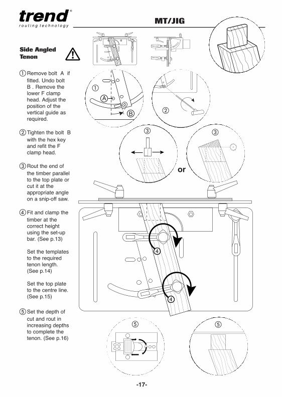
Side Angled
Tenon
� Remove bolt A if fitted. Undo bolt B . Remove the lower F clamp head. Adjust the position of the vertical guide as required.
� Tighten the bolt B with the hex key and refit the F clamp head.
� Rout the end of the timber parallel to the top plate or cut it at the appropriate angle on a snip-off saw.
� Fit and clamp the timber at the correct height using the set-up bar. (See p.13)
Set the templates to the required tenon length. (See p.14)
Set the top plate to the centre line.(See p.15)
� Set the depth of cut and rout in increasing depths to complete the tenon. (See p.16)
MANU-M&T v2.3 16/11/10 14:38 Page 17

MT/JIG
-18-
Front Angled
Tenon
or
When angle isgreater than 20°move top F clampto its lower position.
� �
� �
� �
� Remove the two side bolts. Adjust the tilting back plate to the position required.
� Tighten the two side bolts with the hex key.
� Rout the end of the timber parallel to the top plate or cut at the appropriate angle on a snip-off saw.
� Fit and clamp the timber at the correct height using the set-up bar. (See p.13)
Set the templates to the required tenon length. (See p.14)
Set the top plate to the centre line. (See p.15)
� Set the depth of cut and rout in increasing depths to complete the tenon.
MANU-M&T v2.3 16/11/10 14:38 Page 18

MT/JIG
-19-
Support Piece
Setting Up for
the Mortise
� Clamp the timber for the mortise horizontally flush underneath the top plate.
� When narrow timbers are to be used and when the mortise is at the end of the timber, the fourth F clamp can be used to secure it. The plastic cap should be fitted as shown.
� A scrap piece of timber can also be clamped vertically to give support and to assist in positioning of the horizontal timber.
This alternative set-up with fourth F clamp fitted in position on the left slot of the tilting back plate can be used.
Wider timber can be also accommodated by using the top clamp of the vertical guide.
Or removing the vertical guide and clamps and using a clamp in the left slot of the tilting back plate.
A
�
A
B
C
D
When cutting at the end of
the timber it is advisable to
add extra support or
alternatively use a longer
length of timber and then
cut it to length.B
CD
MANU-M&T v2.3 16/11/10 14:38 Page 19
MT/JIG
-20-
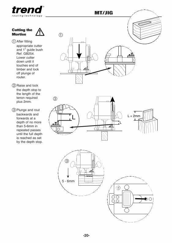
Cutting the
Mortise
5 - 6mm
� After fitting appropriate cutterand 1” guide bushRef. GB254. Lower cutter down until it touches end of timber and lock off plunge of router.
� Raise and lock the depth stop to the length of the tenon required plus 2mm.
� Plunge and routbackwards and forwards at a depth of no more than 5-6mm in repeated passes until the full depth is reached as set by the depth stop.
L + 2mm
LL
3
�
�
�
MANU-M&T v2.3 16/11/10 14:38 Page 20

MT/JIG
-21-
Square Mortise
& Tenons
Tenons
� Release locking levers.
� Turn each template around.Set-up positions of top plate and templates as for round tenons.
� Rout in a clockwise direction following the template.
Mortise
� The mortise is routed in the same way. Square the ends of the mortise with a suitable size of chisel.
�
�
�
�
MANU-M&T v2.3 16/11/10 14:38 Page 21

MT/JIG
-22-
Dowelling
+ =
xRef. GB159
5/8"
x
� Select and fit the 5⁄8" plastic guide bush and a straight router cutter to suit the diameter of the dowels being used.
� Select the short or long template depending on the formation of holes to be used.
� Mark the timber centre line and dowel positions. Note the template hole centres are at 1" (25mm) centres.
� Set-up and secure the timber in the same way as for mortise and tenons. But align the top plate using the centre line notches on the template holes. Set the cutter depth to slightly more than half the dowel length.
Locate the guide bush in each holeand rout the holes in a series of plunge cuts to prevent waste from packing around the cutter.
CL
�
�
�
�
MANU-M&T v2.3 16/11/10 14:38 Page 22

MT/JIG
-23-
MAINTENANCE
This jig has been designed to operate over along period of time with a minimum ofmaintenance. Continual satisfactory operationdepends upon proper tool care and regularcleaning.
Cleaning
■ Regularly clean the jig with a soft cloth.
Lubrication
■ Your jig requires no additional lubrication.
� Position the horizontal timber tight to the underside of the top plate.
� Then clamp it securely using a vertical timber piece as asupport.
� Plunge rout the holes as before.
Use the short plate for an alternative formation of holes.
A
B
A
B
Dowelling the Horizontal Timber Section
ENVIRONMENTAL PROTECTION
Recycle raw materials instead of disposingas waste.Packaging should be sorted for environmental-friendly recycling.
The product and its accessories at the end of itslife should be sorted for environmentally friendlyrecycling.
GUARANTEEThe unit carries a manufacturers guarantee inaccordance with the conditions on the enclosedguarantee card.
MANU-M&T v2.3 16/11/10 14:38 Page 23

MT/JIG
-24-
MT/JIG - SPARE PARTS LIST v2.0 01/2004
No. Qty. Desc. Ref.1 4 F Clamp for MT/JIG WP-MT/012 1 MT/JIG Set-up Bar UK WP-MT/02/UK
1 MT/JIG Set-up Bar EURO WP-MT/02/EURO3 1 Label Trend MT/JIG WP-MT/034 1 Main Body WP-MT/045 1 Vertical Guide WP-MT/056 1 Inner Body WP-MT/067 1 Tilting Back Plate WP-MT/078 1 Top Plate WP-MT/089 1 Back Clamp Plate Packing Piece WP-MT/0910 3 Pivot Bush WP-MT/1011 1 F Clamp Square Cap WP-MT/1112 1 Back Clamp Plate WP-MT/1213 1 Front Clamp Plate Packing Piece WP-MT/1314 1 Front Clamp Plate WP-MT/1415 1 Template Long WP-MT/1516 1 Template Short WP-MT/1617 2 Adjustable Lever M6 x 15mm CR/KB/PK818 3 Machine Screw Button M6 x 16mm Skt WP-SCW/7519 2 Adjustable Lever M6 Female CR/KB/PK920 2 Nut Hex M6 WP-NUT/0621 2 Washer M6 Form C WP-WASH/1222 6 Machine Screw Button M6 x 12mm Skt WP-SCW/7323 1 Guide Bush Set Plastic Imperial 6 off UK WP-MT/23/UK
1 Guide Bush Set Plastic Metric 6 off EURO WP-MT/23/EURO24 1 Guide Bush 25.4mm (1”) Diameter UK GB254
1 Guide Bush 30mm Diameter EURO GB3025 1 Guide Bush Collar 25.4mm to 54mm UK GB/COLL/25454
1 Guide Bush Collar 30mm to 54mm EURO GB/COLL/305426 1 T Handle Hex Key 4mm x 150mm HK/T/0427 4 Self Tapping Screw Pan No.10 x 3⁄4 Pozi WP-SCW/10828 2 Clamping Bar Shims WP-MT/2829 1 Manual MANU/MT
DUST EXTRACTION KIT (OPTIONAL)
30 1 Dust Kit Complete MT/DUSTKIT31 1 Dust Shield WP-MT/3132 1 Dust Spout WP-SRT/1633 1 Magnet Pack 10mm x 3mm (Pack of 4) MAG/PACK/234 4 Machine Screw Button Flange M6 x 12mm Skt WP-SCW/7335 4 M6 Internal Shakeproof Washer WP-WASH/3136 4 Nut Hex M6 WP-NUT/0637 0 Hose Adaptor 58mm to 39mm CRT/338 1 Adaptor Body for CRT/3 WP-CRT/9739 1 Adaptor Fitting for CRT/3 WP-CRT/9840 1 Adaptor Clip for CRT/3 WP-CRT/99
CUTTER SETS (OPTIONAL)
41 0 Cutter Set Imperial 5pc UK SET/MT10 Cutter Set Metric 5pc EURO SET/MT2
MANU-M&T v2.3 16/11/10 14:38 Page 24

MT/JIG
-IB-
17
21
21
1712
169
14
138
2019
2019
4
27
6
7
22
18
5
10
18
22
22
18
15
27
23
25
24
11
1
22
2
26
10
10
3
MT/JIG
29
22
28
28
L
5/8"1/2"
3/8"5/16"
1/4"
15.9mm
12.7mm
9.5mm
7.9mm
6.4mmTENON WIDTH
5/8" 15.9
1/2" 12.7
3/8" 9.5
5/16" 7.9
1/4" 6.4
R5/8" 1
5.9
1/2" 12.7
3/8" 9.5
5/16" 7.9
1/4" 6.4
Align with tenon end
& position templates
MORTIS
E & TENON JIG
SET-UP B
AR
1. Set Timber H
eight
2. Set C
entre Line
3. Set Tenon Length
GB222
GB254
GB286
GB302
GB318
C026
C022
C015
C012
C008
TENON BUSHMORTISE CUTTER
GUIDE BUSH & CUTTER SELECTIONNOTE
For tenon use cutter C
O26
For mortis
e use 2-1/8" collar
WP-MT/02/UK
MT/JIG - SPARE PARTS DIAGRAM
36
31
33
36
37
3438
3940
34
32
30
35
35
MT/DUSTKIT
v2.0 01/2004
MANU-M&T v2.3 16/11/10 14:38 Page 25

MA
NU
/MT
v2.
3
© Copyright Trend 2010. No part of this publication may be reproduced, stored or transmitted in any form without prior permission.Our policy of continuous improvement means that specifications may change without notice. Trend Machinery and Cutting Tools
cannot be held liable for any material rendered unusable or any form of consequential loss. E&OE® All trademarks acknowledged.
RECYCLABLE
Trend Machinery & Cutting Tools Ltd.
Odhams Trading Estate St Albans RoadWatford WD24 7TR EnglandTel: 0044(0)1923 [email protected]
MANU-M&T v2.3 16/11/10 14:38 Page 26