m.tech. civil ( mtst ) - spce
TRANSCRIPT

Qt( ; --> x
Bharatiya Vidya Bhavan's
Sardar Patel College of Engineering (A Government Aided Autonomous Institute)
Munshi Nagar, Andheri (West), Mumbai —400058. Re Exam June 2018
Max. Marks: 100 Duration: 3 Hours
Class: M.Tech. Semester: II Program: Civil Engineering with Structural Engineering
Name of the Course: Earthquake Engineering Course Code : MTST154
Instructions: • Attempt any FIVE questions out of SEVEN questions.
• Answers to all sub questions should be grouped together. • Figures to the right indicate full marks. • Assume suitable data if necessary and state the same clearly.
Question No
1
Max. Marks
Course Outcome No.
Module 11 No.
i
Q1 (a)
Answer the followings:
(i) Explain clearly, the difference between static and dynamic I 3
analysis of structure
(ii) What is an earthquake? How the earthquakes are classified
based on their causes?
(iii) Explain the different types of seismic waves and their
characteristics
3
4
1
3
3
,
1
2 I
2
Q1(b)
(i) A uniform rigid slab of total mass 25 t is supported by four columns of height 8.0 m. rigidly connected to the top of slab and fixed at bottom. Each column is
rectangular section of 750 mm x 300 mm as shown if figure. If the system is subjected to harmonic ground motion of amplitude 0.3g at frequency of 10 radisec in X direction only, calculate the maximum lateral displacement of slab in X direction and maximum stress in each column C = 5% and E = 20, 000 MPa.
(ii) In the above problem, If the columns are hinged at bottom, then calculate the maximum lateral displacement of slab in X direction and maximum stress in each column. Comment on the effect of fixity of column on these parameters
4
3
2
2
1
,
1
Qi (0. Explain the characteristics of groundotions 3 3 3
4/1f
0-) !u 0
(
, i
Q2 (a)
A free vibration test is conducted to determine the dynamic properties of a one storey building. The mass of the building 10t. Initial displacement of the building is 60 mm. Maximum displacement on the first cycle is 40 mm and period of 'displacement cycle is 1.5 sec. Determine:
(i) Un damped frequency (ii) Logarithmic decrement (iii) Damping ratio _(iv) Damping coefficient (v) Amplitude after 6 cycles.
is 1 5 1 1
Q2 (b)
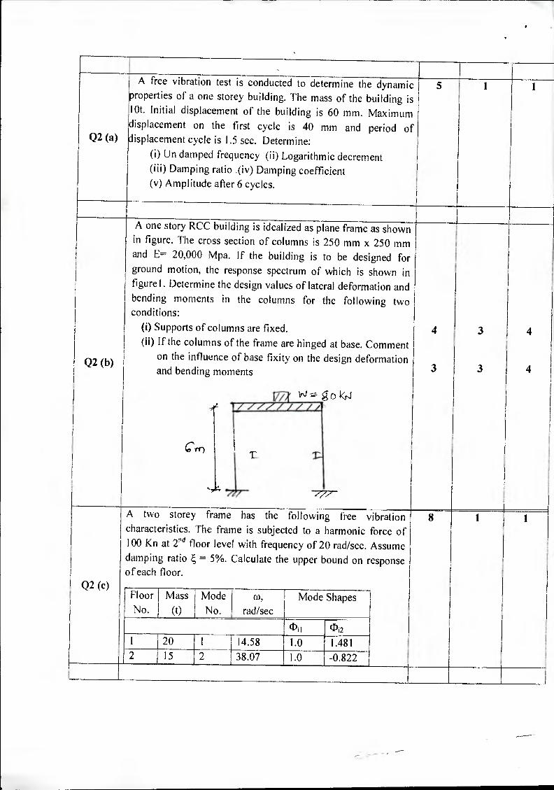
A one story RCC in figure. The cross and E= 20,000 Mpa. ground motion, the figure I. Determine bending moments conditions:
(i) Supports of columns (ii) If the columns
on the influence and bending
building
the in
of
section
response
moments
is idealized as plane of columns is
If the building is spectrum of
design values of lateral the columns for the
are fixed. the frame are hinged
of base fixity on the
// wgckJ
frame 250 mm x to be designed which is
deformation following
at base. Comment design deformation
as shown 250 mm
for shown in
and two
4
3
3
3
4
4
IMIGIGIFAIIWANIN
r
,,,,
Q2 (c)
A two storey frame has the following free vibration characteristics. The frame is subjected to a harmonic 100 Kn at 2nd floor level with frequency of 20 rad/sec. damping ratio = 5%. Calculate the upper bound on response of each floor. ,
force of Assume
8 1 1
' Floor 1 Mass Mode i No. 1 1 (t) No.
ci), rad/sec
Mode Shapes
0,1 0,2 1 20 I 14.58 1.0 1.481 2 15 2 38.07 1.0 -0.822
co y A
3 c,o1
Go0
.1300
o re) 0o
X
200
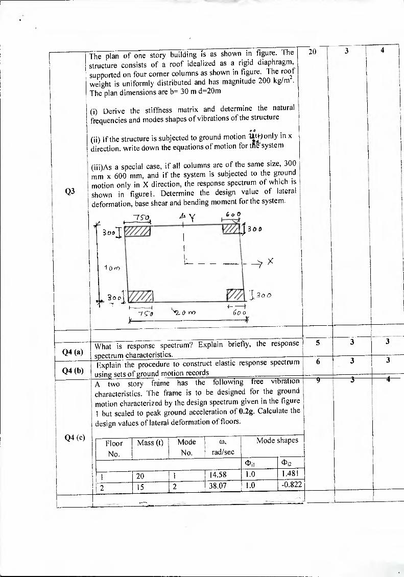
The plan of one story building is as shown in figure. The structure consists of a roof idealized as a rigid diaphragm, supported on four corner columns as shown in figure. The roof weight is uniformly distributed and has magnitude 200 kg/m2.
The plan dimensions are b= 30 m d=20m
(i) Derive the stiffness matrix and determine the natural frequencies and modes shapes of vibrations of the structure
"0
(ii) If the structure is subjected to ground motion am only in x
direction. write down the equations of motion for tRt system
(iii)As a special case, if all columns are of the same size, 300 mm x 600 mm, and if the system is subjected to the ground motion only in X direction, the response spectrum of which is
Q3
shown in figure 1 . Determine the design value of lateral deformation, base shear and bending moment for the system.
20 3 4
5
6
9
3
3
3
What is response spectrum? Explain briefly, the response Q4 (a)
spectrum characteristics. Explain the procedure to construct elastic response spectrum
Q4 (b) using sets of ground motion records A two story fiime has the following free vibration characteristics. The frame is to be designed for the ground motion characterized by the design spectrum given in the figure 1 but scaled to peak ground acceleration of 0.2g. Calculate the design values of lateral deformation of floors.
Q4 (c) Mode shapes Floor Mass (t) Mode co,
No. No. rad/sec
(pit CI) i2
20 14.58 1.0 1.481
2 15 38.07 1.0 -0.822

Q5(a)
The plan of one storey building is as shown in figure. The structure consists of a roof idealized as a rigid diaphragm, supported on three frames A, B, and C as shown. The roof weight is uniformly distributed and has magnitude 250 Kg/m2. The lateral stiffness are Ky = 30000 KN/m for frame A and Kx =25000 KN/m for frames B and C. The plan dimensions are b.--30 m d=20m. The height of building is 8m. (i) Derive the stiffness matrix and determine the natural frequencies and modes of vibrations of the structue (ii)lf the structure is subjected to ground motion up only in X direction, write down the equations of motion for the system (iii) If the system is subjected to the ground motion only in X direction, the response spectrum of which is shown in figure 1. Determine the design value of lateral deformation, base shear and bending moment for the system
i )
/ \( ,c r-„Iy.a A
9 3 4
' f /4111.1111g1 ,
d
GI
2-
a YLll ,-.)
4"
1
— -4---
A'
----1> X
. V/i i VA 1/N t, r----- l'' f>
Q5(b) Explain the following with reference to SDOF systems:
(i) Allowable Ductility (ii) Ductility Demand
4 4 4 I
Q5(c) State the limitation of Equivalent Static Method. As per IS 1893-2016, under what conditions the seismic coefficient
method is permitted to use to calculate the earthquake forces.
3 3 6
Q5(d)
Define the following: (i) Random process (ii) Stationary process (iii) Ergodic process (iv) Autocorrelation function (v) Power spectral density function
4 4 5 1 1 I
1
Q6 (a) 2016
Explain the various types of Irregular Buildings as per IS 1893- 4 3 6
Q6(b) Explain the three requirements of displacement design of
structure for earthquake load as per IS 1893-2016. 4 3 6
Q6(c) As per IS 1893-2016, how many mode need to be considered in the earthquake force calculation by Response Spectrum Method
2 3 6

Type I ROCK OR HARD SOIL
-- Type II MEDIUM SOIL
Type 11 SOFT SOIL
3.0
Q6(d)
Using response spectrum methoa, calculate the seismic force on each floor of the framc whcse pre vibration properties are given below. Use the following additional data: Z=0.24, I =1.5, R=5.0 and 5%. Assume foundation strata as soft and use response spectrum given in figure 2.
Story No.
Mass No.
Mass (t)
co rad/sec
Mode shapes
Oil 4312 (Do 1 30 15.73 0.399 0.747 1.0
2 2 30 1 49.85 1.0 0.727 -0.471 30 77.82 -0.908 1.0 -0.192
10 4 6
Q7(a)
Q7(b)
What is shear Wal ? Explain the advantages of shear walls.
What is ductility of a structure? Explain the importance o ductility in seismic resistant structures.
3 7
Q7(c)
Q7(d)
Explain the provisions of IS 13920 for 12 (i)Beams: General provisions, longitudinal reinforcement and web reinforcement (ii) Columns: General requirements, longitudinal reinforcement and shear reinforcement
Briefly explain the earthquake design principle as per IS 1893- 2 2016 (i.e. fail safe criteria)
3 6
0 1 2 3 4
5 6 NATURAL PERIOD T, s
28 SPECTRA FOR RESPONSE SPECTRUM METHOD
FIG. 2 DESIGN ACCELERATION COEFFICIENT (Sa/g) (CORRESPONDING TO 5 PERCENT DAMPING)
-2 6 (d)

t
•
0 1211,•••••0,•••4. *T.. .a.e.•
• • ! •
o <. • tr- k
4.
StiSitSW NI' • • INMAGIOV14100
:Les

Bharatiya Vidya Bhavan's
Sardar Patel College of Engineering (A Government Aided Autonomous Institute)
Munshi Nagar, Andheri (West), Mumbai — 400058.
End Semester Examination May 2018
Max. Marks: 100 Semester: II Class: M.Tech-Structure Name of the Course: THEORY OF PLATES (TOP)
Instructions: • Attempt any FIVE questions.
Answers to all sub questions should be grouped together. Figures to the right indicate full marks. Assume suitable data if necessary and state the same clearly.
Duration: 3 Hours Program: PG-M.Tech Course Code : MTST 152
Question No
Max Marks
Module No.
Q.1(a) Show that the sum of the curvatures in two perpendicular directions such as 'n' and t' is independent of the angle 'a', so it is constant. Also find the direction of principal curvature.
14 2
(b) 4 q Derive Lagrange's equation for plate, V w=—
D
06 3
Q.2(a) Derive the equations for deflection of a long rectangular plate subjected to UDL and bending to a cylindrical surface with clamped edges from first principal and give expressions for stresses and moments in the plate.
15
(b) Explain boundary conditions for i) clamped ii) simply suppOrted and iii) free edge for plates.
05
Q.3(a) Derive relation between bending moment and curvatures for a rectangular plate subjected to pure bending moment Mx and My acting along x and y direction edges respectively. Also derive the relation between these moments and normal and twisting moment on any arbitrarily inclined plane passing through a point.
15 2
(b) Distinguish between plates and shells. 05 1
Q.4 Derive the expressions of Navier's solution for rectangular plate and using it develop expression for maximum deflection of a uniformly loaded square plate with simply supported edges.
20 6
Q.5 A circular steel plate having 1.6m diameter and 2 cm thickness is subjected to a UDL of 0.5 KN/m2. Write down the expressions for the deflections and moments at a distance 'r' from the centre and calculate their values at a radial distance of 1 m from the centre as well as the centre itself, when:
(a) The plate is clamped at the edges; and
20 4
PTO
1

(b) The plate is simply supported at the edges. Given E--- 2x10⁵ N/mm2 and 11= 0.3
Q.6 Derive the expressions of Levy's solution for deflection of uniformly loaded simply supported rectangular plates.
20
Q.7(a) 15 A simply supported plate of size 5h x 5h is subjected to UDL qo over the
entire surface. Take grid size h x h , using finite difference method determine deflection and moments at all points of intersection.
7
(b) Explain double fourier form for uniformly distributed load over small area. 05 5
******BEST OF LUCK******
2

Bharatiya Vidya Bhavan's
Sardar Patel College of Engineering (A Government Aided Autonomous Institute)
MunShi Nagar, Andheri (West), Mumbai — 400058.
Final Examination May 2018
Max. Marks: 100
Duration: 3 Hour Class: FY M.Tech Semester: II
Program: MTech (Civil) in Structural Engineering
Name of the Course: Finite Elment Analysis Course Code: MTST151
Instructions: • Attempt any Five questions out of Seven questions. • Answers to all sub questions should be grouped together. • Figures to the right indicate full marks. • Assume suitable data if necessary and state the same clearly.
Question Max
No Marks
Q.1. Write detailed notes on any four out of following six — [201 (a) Serendipity elernents. (5) (b) Iso-parametric elements. (5) (c) Use of Jacobian Matrix in finite element method. (5) (d) Similarity & di erences between the plane stress and plain strain elements. (5) (e) c°, C1 and C2 c ntinuous elements. (5) (f) Gauss-quadrature numerical integration technique. (5)
1
Q.2 1201 (a) What are geon4tric and material non-linearity? (2) (b) Considering the geometrically non-linear spring shown in figure below; if (8)
K(u) = 20u2 + 200 N/mm and P = 1.140 KN; find the displacement u.
(c) For the unconstrained stepped bar shown in figure below; find, natural (12) frequencies of lOngitudinal vibration, mode shapes and [MI-orthogonal mode Shapes. Take E 4 p as constant.
Area = 2A Area = A
L/2 -4-
L/2
1

Q.3 For the two member truss shown in figure below, assume AE to be constant for both [20] members, find the reactions and the member forces.
5 KN
Q.4. [20]
(a) For three bar assemblage shown in figure below; Find — 1. Displacement At Nodes 2 & 3 2. Reactions At Nodes 1 & 4
1
, A I
2 loomm /1, !oornm A„ 100mm Az
Al = A2 = 100 Sq.mm. El= E2 10 x 101() Pci A3= 200 Sq.mm. E3 = 5 x 101° Pa
(10)
(b) Enlist general steps in finite element method and also enlist its advantages and (10) disadvantages.
Q.5. [20]
(a) Derive the shape fiinctions for Lagrange's 9 noded rectangular element. (10)
(b) With neat sketches explain in detail discretization process and the various types (10) of elements used in discretization of structure.
Q.6. Analyze the two member rigid frame shown below. [20] For both members take E = 200 GPa; Izz = 1.33x10⁻⁴ m4 and A= 0.04 m2.
48, KN
2m 2 m —1
I 24 KN
2

Q.7. [20]
(a) For the simply supported beam shown in figure below; compare results of (8) maximum deflection and bending moment using 1. Rayleigh-Ritz Method And 2. Exact Value
(b) Write note on — 1. Convergence & Compatibility Requirement 2. Geometric Invariance 3. CST element
(12)
3
Bharatiya Vidya Bhavan's
Sardar Patel College of Engineering (A Government Aided Autonomous Institute)
Munshi Nagar, Andheri (West), Mumbai — 400058.
End Semester Examination May 2018
Max. Marks: 100 Class: M.Tech (Str) Semester: II Program: M.Tech (Structural Engineering)
Name of the Course: Elective-II Advanced Design of Concrete Structures Course Code: MTST 156
Instructions: • Attempt any FIVE questions out of SEVEN questions. • If there are sub questions, answers to all sub questions should be grouped
together. • Figures to the right indicate full marks. • Assume suitable data if necessary and state the same clearly.
• Use of codes IS 456:2000, IS 4995:1974 (Part I & Part II) is allowed.
Question No
Q.1 (a) Using Whitney's stress block, find the ultimate moment of resistance of a reinforced concrete beam of rectangular section 300 mm x 750 mm reinforced with 3 numbers of 32 mm diameter bars. Use M25 concrete and Fe415 steel. Use effective cover to tension steel as 50 mm.
Q.1 (b) If the rectangular section referred in Q1 (a) above is made monolithic with 160 mm thick R.C. C. slab of the same grade and top level flush with top of the beam, find the ultimate moment of resistance of the resulting T section assuming flange width as 1500 mm. Use Whitney's
stress block.
Q.2 (a) Differentiate between plastic analysis of steel structures and limit analysis of reinforced concrete (RC) structures.
Q.2 (b) A reinforced concrete slab of depth 150 mm and of effective plan dimensions of 4m X 5m size is simply supported on all its edges. The working load due to finish is 2.0 k.N/m2 and superimposed live-load is 3
kNitn2. The amount of reinforcement at the bottom provided along long
Duration: 3 Hours
span is 85% of that provided along short-span. Analyse the slab using yield line theory, considering load factor of 1.5. Use M 25 grade concrete and Fe415 steel.
Max Marks
Course Outcome Number
Moduli No.
(10) 1 1
(10) 1 1
(05) 1 2
(15) 1 3
1

Q.3 (a) Derive the expression for rotation capacity of a compression hinge used in limit analysis of RC structures.
Q.3 (b) Explain the concept of Moment-redistribution.
Q.3 (c) Differentiate between two way slab and flat slab. What are the advantages and disadvantages of flat slabs?
Q.4 (a) Calculate the moment of resistance of the concrete beam having a width of 280 mm and a depth of 500mm. It is reinforced with 4 nos 25 mm diameter TOR bars on tension side and 4 nos 16 mm diameter TOR bars on compression side. Assume effective cover of 40 mm for both tension and compression steel. Use M 25 grade of concrete and Fe 415 grade of steel.
Q.4 (b) A reinforced concrete slab of effective plan dimensions of 4m X 5m size is simply supported on all its edges. The working load due to finish is 2.0 IcNim and superimposed live-load is 3 IcN/m2. Design the slab using limit state method. Considering load factor of 1.5. Use M 25 grade concrete and Fe415 steel.
Q.5 (a) Derive the expression for finding lateral pressure due to stored material on silo using Janssen's theory.
Q.5 (b) Write short note on hoop tension in hopper of cylindrical silo.
Q.5 (c) What are advantages and disadvantages of folded plates as compared to shells?
Q.6 A circular wheat silo is has an internal diameter of 6.5m and a wall height of 22m. It has a conical hopper of height 2.5m. The inner diameter of the opening at the base of the hopper is 0.4m. Design the silo wall and hopper bottom. Density of wheat is 8 KN/m3 Angle of
internal friction is 18° and co-efficient of friction between wheat and concrete wall is 0.4. Use M20 concrete and Fe 415 steel.
Q.7 (a) Explain the steps involved in Whitney's method of analysis of folded plate.
Q.7 (b) Explain the Plate action and slab action in folded plate analysis.
(10) 1 2
(04) 1 2
(06) 1 5
(10) 1 4
(10) 1 5
(10) 2 6
(06) 2 6
(04) 2
(20) 2 6
(16) 2 7
(04) 2 7
2
BharatiyaVidyaBhavan's
Sardar Patel College of Engineering (A Government Aided Autonomous Institute)
Munshi Nagar, Andheri (West), Mumbai — 400058.
cvo,,:se
Max. Marks: 100 Class: FY M.Tech Semester: II Name of the Course: Bridge Engineering
Re-Examination June 2018
Duration: 3 Hours Program: M.Tech. in Structural Engineering
Course Code: MTST153
Instructions: • Answers to all sub questions should be grouped together. • Answer any 5 questions. • Figures to the right indicate full marks. • Assume suitable data if necessary and state the same clearly.
Question No.
Max Marks
Course Outcome Number
Module No.
Q.1 A) For the carriageway width of 13m and span of 25m, draw neat sketches to explain all live load cases to be considered in longitudinal as well as transverse design using IRC: 6-2017 provisions for RC'C structure.
B) Calculate the Cotrbon's factors for 3 girders equally spaced at 2m c/c, the bridge is symmetrical in transverse direction with carriageway of 6 m for 1 lane of IRC class A vehicle loading.
12 + 8 1 2
Q.2 A) Shown below is a simply supported span of 20m. on a single fixed(FX) and free (FR) bearing Calculate maximum bearing forces on these vehicle plying on the span. Check Annexure details.
20m *— *
It is supported on each end.
bearings for a SP I for SP vehicle
FR
of using a PSC
Explain typical Spill through type
6+4+10 I 4 4,6 FX E8) 0
B) Write any 2 advantages and any 2 disadvantages box girder as superstructure in a bridge.
C) Explain 3 types of abutments with sketches. details at "superstructure connection" for a abutment.
1

Q.3 I Design a pile cap with following details: grade of concrete M40, grade of steel Fe500D Pier dimensions = 1.6m K1 .6m
,
4 Piles of lm diameter symmetrically placed within the pile cap
Design Loads in ULS are: Vertical Load, P = 6000kN, Longitudinal Moment ML = 45001cN-m, Transverse moment MT = 40001(N-m
20 4 6
Design shall follow IRC 78- 2014 and IRC: 112-2011 guidelines. Check for flexure in both orthogonal directions (longitudinal & transverse) using Rectangular-Parabolic stress block. Draw a neat sketch to show reinforcement detailing of the pile cap.
Q.4 Calculate base pressure at each corner of the square foundation with sides 7mresting on soil.
Design Loads: Vertical Load, P = 8000kN, Longitudinal Moment ML = 4000kN-m and, Transverse moment MT = 35001N-m SBC of bearing strata is 50 T/m2 Pier dimensions = 3.2m(iransverse) x 1.6m(longitudinal)
Check for bearing pressure along with appropriate allowed tension. 20 4 6
Use a partial safety factor of 1.5 for ULS design of the foundation. Design the foundation for flexure only in the critical direction and provide symmetrical reinforcement in each direction. Take concrete grade M40 and Fe 500D steel. Design shall follow IRC: 112-2011 guidelines.
Draw a neat sketch to show reinforcement detailing of the foundation. ; i
Q.5 Steel composite girder bridge having 3 steel plate girders, 30 m span calculate the following as per IRC:6 and IRC:22:
1. Temperature stress for both rise and fall 10+10 4 5
2. Shear connector spacing with Stud connectors for 60T DL shear force.
Following assumptions to be considered:
2

c/c of girder — 3.0m, overall width = 10.5m, footpath width = 1.5m each side, carriageway width — 7.5m., Thickness of deck slab = 250mm. Grade of concrete- M40, Grade of Steel -Fe410. Assume deck slab steel provided 160 @150mm c/c (both ways) For 20mm dia Stud connector Qu =115 KN, Qr =25 KN, H= 100mm.
I 425 x 20
1700 x 16
I 425 x 20
Q.6 A. What are the classification of bridges as per 1. Form of superstructure 2. Functional requirement
B. A suspension cable 160m span and 16m central dip having 10 KN/m. (i) Calculate the maximum and minimum tensions in the cable. (ii) Horizontal and vertical force on each pier considering cable passes 3+15+2 2A 1,5,7 over frictionless rollers on the top of pier. The back stay is inclined at 30° (iii) Calculate the length of the cable.
C. What are the components of a Through Type Truss bridge show with a neat sketch.
Q.7 A. Design a cantilever slab for class A load for RCC T beam girder considering following considering crack width check: No of RCC T-girder 3 with c/c spacing 2.75m, Deck slab thickness 0.25m and 0.15m at tip, Total width of llm with footpath of 1.5m width Span length of 20m Thickness of girder web 0.3 m. Grade of concrete M40, Steel Fe 500D Draw a neat Sketch.
10+10 4 3
B. Draw the force diagram of 3.5 x 3.5 m (clear dimension) Box culvert for Class A loading with following conditions: (i) Total width of llm with footpath of 1.5m width
(ii) Having uniform thickness of 0.4m of each side wall and both top
and base slab. i 1
(iii) full water condition ! 1 1 (iv) soil friction coefficient 41=300
3