mri radio frequency shielding · mri basics in layman’s terms, the human body consists of...
TRANSCRIPT

MRI RadioFrequencyShielding SITE PLANNING GUIDE


Introduction ...................................................................................... 4 - 8
Chapter One - MRI Basics ............................................................... 9 - 14
Chapter Two - Radio Frequency Shielding ................................ 15 - 20
Chapter Three - Magnetic Shielding ........................................... 21 - 24
Chapter Four - Siting Considerations ......................................... 25 - 28
Chapter Five - Shielding Details Overview ................................ 29 - 31
- IMPERVIUS™ MRI Copper Panel System ............ 32 - 40
- IMPERVIUS™ MRI Galvanized Panel System ..... 41 - 49
- IMPERVIUS™ MRI Soldered Copper System ..... 50 - 58
Table of Contents

INTRODUCTIONWho should review this guide?Facility managers, electrical and mechanical contractors, as well as architects and designers.
Information provided within the NELCO Worldwide Site Planning Guide is an aid to increasing your general knowledge and for planning your MRI facility. This is not a substitute for the site planning information of the MRI vendor whose equipment you are purchasing. Not every aspect of RF or Magnetic shielding can be addressed in this brief guide, however we have tried to give you a well-rounded view of the most common issues/concerns.
Magnetic Resonance Imaging (MRI) is a diagnostic imaging tool much like X-ray, except it uses RF frequency and magnetic field instead of radiation. An MRI system therefore needs to isolate the exam room from outside RF noise (local TV stations, cell phones, etc.) so it detects only the patient’s response to the RF frequency being broadcast. RF (Radio Frequency) shielding is required for EVERY MRI system.
RF shielding can be done with nearly any type of metal, however the most commonly used metals are copper, galvanized steel or aluminum. It should be noted that RF shielding MUST surround the MRI room, i.e., all walls, ceiling and floor. RF signals can transmit through concrete and earth, albeit to a lesser degree than open air but still enough to interfere with the MRI’s ability to get a clean image of the patient.
Questions and comments relating to
this guide can be directed to:
Global Director for RF Shielding
NELCO Worldwide
781.537.3011
Magnetic field is mainly a concern when looking at the MRI-generated field versus what it may impact around the MRI exam room.
4
Pho
ne: 7
81.9
33.1
940
N
ELC
OW
OR
LDW
IDE.
CO
M

5
This differs from X-ray shielding, where you only need to shield for the line of path of the radiation, sometimes called “line of sight.”
An MRI also uses a strong magnetic field, along with the RF frequencies, to create the image of the patient.
The 5-gauss field, a simple measure of the magnetic field, is the global guide to protect those people with pacemakers or metal implants from the MRI-generated magnetic field. Thus, if the 5-gauss field will extend into a hallway, waiting area or other “uncontrolled” space where people may go, magnetic shielding must be used to protect those people from exposure to the 5-gauss field.
These things create a type of magnetic field that can interfere with the MRI, i.e., making the MRI unable to produce a clean
image of the patient. Magnetic shielding may or may not be sufficient to guard against these disturbances. Often MRI vendors will consult the hospital/clinic to place the MRI far enough away so these disturbances do not affect the MRI. When this is not possible, magnetic shielding will need to be considered. The shielding solution can vary from site to site because of the uniqueness of each site, so the hospital/clinic should employ an MRI vendor or other MR/RF/Magnetic expert to ensure that they plan properly early on to avoid problems later in the overall planning/construction/installation cycle.
Another concern of the magnetic field is that which is generated by moving cars, trucks, buses, electrical substations or other significant power line/equipment.
Pho
ne: 7
81.9
33.1
940
N
ELC
OW
OR
LDW
IDE.
CO
M

6
the MRI machine. This third layer of glass can easily be added by the interior finishes contractor.
Most MRI systems today use liquid helium to operate.
This requires a pipe, called a “quench pipe,” to be attached to the MRI and vented to the outside of the building.
The concern here is that liquid helium is very cold, and if, for some reason, there was an accident (usually called a “quench” where the pipe breaks or leaks due to the extreme cold or pressure), people could be harmed by the quickly expanding gas. All MRI vendors provide guidance to the mechanical contractor on how to construct and attach the quench pipe properly and safely.
It should be noted that most MRIs create a great deal of noise as they run through the imaging sequences.
As such, consideration should be given to planning good sound-deadening elements into the MRI room construction.
Most of the sound deadening will come through proper design and construction of the walls, ceiling and floor of the space. The RF shield can provide some sound attenuation as well, however the most important elements of the RF shield, from a sound attenuation perspective, are the RF door and window. The RF door must be designed to provide good sound attenuation; typically a rating of STC 40 or higher is recommended. The RF window usually comes with two layers of glass. The process of adding a third layer of glass is usually sufficient to buffer the noise from
Pho
ne: 7
81.9
33.1
940
N
ELC
OW
OR
LDW
IDE.
CO
M

Last, because most MRI systems generate a very strong magnetic field in order to create the images of the patient, MRI safety is coming to the forefront in site planning more and more!
Magnetic objects, if brought close enough to the MRI, could be quickly and strongly pulled into the MRI.
The force and speed at which this can happen is “deadly”! Ensuring that some system/methodology is in place to be certain ferrous materials are never brought
into the MRI room, whether intentionally or accidentally, is slowly becoming a mandate. As of the writing of this guide, it is not currently a requirement but is in discussion by several agencies to make it a requirement.
7
Pho
ne: 7
81.9
33.1
940
N
ELC
OW
OR
LDW
IDE.
CO
M

Pho
ne: 7
81.9
33.1
940
N
ELC
OW
OR
LDW
IDE.
CO
M
8

MRI BasicsC H A P T E R O N E

CHAPTER 1 • 10
ZRF
Y
X
Z
Y
X
Z
S
Y
X
RF
N
ZRF
Y
X
Z
Y
X
Z
S
Y
X
RF
N
ZRF
Y
X
Z
Y
X
Z
S
Y
X
RF
N
MRI BASICS
In layman’s terms, the human body consists of billions of molecules, all with their own magnetic dipole, each randomly oriented within the body. An MRI creates an image of the patient by placing the patient in a very strong magnetic field, which will align the many billions of molecules in a north-south position [Image 1] within the MRI. A specific RF signal is generated by the MRI scanner to elicit a reaction from specific molecules of the patient.
As an example, a “specific RF signal” may be an RF pulse at 30.497 MHz, which may be the resonance frequency of a certain molecule. Thus, those molecules will “resonate” or oscillate [Image 2] and generate a response RF signal [Image 3]. As the MRI scanner runs through a series of “specific” RF signals and collects responding signals from the patient’s body, it can formulate an image from this information.
1.1 Image of the Patient
[Image 1] Molecule at rest
Molecule orientation in magnetic field
The entire body is made of molecules with a magnetic dipole
[Image 2] Resonating from
RF signal
[Image 3] RF reply signal- effect
of resonating
Pho
ne: 7
81.9
33.1
940
N
ELC
OW
OR
LDW
IDE.
CO
M

CHAPTER 1 • 11
1.2 Benefits of a Stronger MRI System
Generally speaking, the benefit of having a stronger MRI system is a stronger signal-to-noise ratio, which merely means the image quality should be better, all things being equal. Additionally, a stronger MRI system should function faster and thus allow for higher patient throughput.
Patient throughput comparison
Image quality
Higher patient throughput and
better image
Higher field MRI, i.e., 3.0T – generally faster scan time
Lower field MRI, i.e., 1.5T
Pho
ne: 7
81.9
33.1
940
N
ELC
OW
OR
LDW
IDE.
CO
M
A higher field MRI system should function faster.

Pho
ne: 7
81.9
33.1
940
N
ELC
OW
OR
LDW
IDE.
CO
M
CHAPTER 1 • 12
When planning an MRI system, one should take care not to place it near large metal objects, i.e., not to place an MRI directly above a structural beam. The metal beam being so close to the MRI will prevent the MRI from establishing a “homogeneous” area where the patient is to be scanned. Thus, when magnetic shielding is to be used, the magnetic shield designer should take care to ensure that no significant amount of steel is too close to the MRI such that it cannot compensate for the steel. This is called “shimming.”
The strength of an MRI is measured in TESLA. A 3.0 Tesla (30,000 gauss) MRI system is approximately twice as strong as a 1.5 Tesla (15,000 gauss) MRI system. For comparison, you can expect to measure 0.5 gauss if you are standing in an open field, away from anything that might artificially create a magnetic field; this is called the earth’s natural magnetic field.
1.4 How MRI Works1.3 MRI or X-rays
MRI is ideal for imaging soft tissue such as heart, lungs, liver, etc. because soft tissue resonates more readily and has a much more pronounced reaction than hard tissue. X-rays, in contrast, are ideal for hard tissue such as bones.
X-ray uses a small amount of radiation that passes through the body to quickly capture a single image of your body. Bone blocks the radiation and thus forms the image.
MRI combines a strong magnetic field with radio waves to get images by capturing molecule reaction to the radio waves.
MRI requires RF shielding, whereas X-rays require radiation shielding. MRI scans can take many minutes to complete; an X-ray can be done in seconds.

How MRI works
Scanner
Radio frequency coil
Magnet coils
Gradient coils
Patient table
Pho
ne: 7
81.9
33.1
940
N
ELC
OW
OR
LDW
IDE.
CO
M
CHAPTER 1 • 13

Pho
ne: 7
81.9
33.1
940
N
ELC
OW
OR
LDW
IDE.
CO
M
CHAPTER 1 • 14
C H A P T E R T W O
Radio Frequency Shielding

Radio Frequency or RF shielding must be a complete enclosure around the MRI, i.e., cover all walls, ceiling and floor. There can be no openings in the RF shield, as RF signals would enter the MRI room and impact the scan image quality. All services for the MRI room must be filtered by either an RF filter or RF waveguide.
RADIO FREQUENCY SHIELDING
2.1 Electrical Systems
RF filter
Electrical power for outlets and lighting must come through an RF filter. Likewise, signals for data – nurse call, code blue, etc. – must come through an RF filter. A connection on the outside of the RF shield is made to wires of the RF filter. On the inside, at the opposite end of the filter, wires are then connected to the requisite electrical outlets, lighting, etc.
A waveguide feedthrough is a “pass thru” device that is sized for the specific frequency of the application. In this case, the application is MRI, and standard sizes exist for waveguides. Usually the length of the waveguide is 4x the diameter of the waveguide.
2.2 Mechanical Systems
Waveguide feedthrough
Usually the length of the waveguide is 4x the diameter of the waveguide.
CHAPTER 2 • 16
Pho
ne: 7
81.9
33.1
940
N
ELC
OW
OR
LDW
IDE.
CO
M

Honeycomb filter
Waveguides are used for air supply/return, water for sprinklers/sinks, medical gases and occasionally for non-metallic
material like fiber optic lines. Note that for gas and water, the waveguide must use a “dielectric” coupling on the outside of the
shield to electrically isolate the shield from the pipe of the gas or water. This is a built-in part of a “sprinkler” or “medical gas” waveguide, therefore be sure to clearly indicate ALL services that need to come into the MRI room.
Be sure to look at everything that comes into
the MRI room! It will need either a filter or waveguide.
CHAPTER 2 • 17
Pho
ne: 7
81.9
33.1
940
N
ELC
OW
OR
LDW
IDE.
CO
M

Pho
ne: 7
81.9
33.1
940
N
ELC
OW
OR
LDW
IDE.
CO
M
CHAPTER 2 • 18
ZincAluminumGalvanized steelMild steel, cast ironLeadTinBrass, bronzeCopperSilver solderStainless steelSilverGraphiteGold
Most anodic or active (likely to corrode)
Most cathodic or passive (protected from corrosion)
Galvanized steel is the second most popular material used. It is easy to come by and more durable against the accidental bumps and damage that can sometimes occur on a construction site. It is heavier and it is magnetic, which means it should not be used or it should be used sparingly when directly underneath the MRI scanner. Of the materials most used for RF shielding, aluminum is the worst in terms of corrosion.
As mentioned earlier, an RF shield can be constructed out of nearly any type of metal, however copper and galvanized metal are the most common materials used. Aluminum is a third, but it represents less than 10% of all MRI RF shields installed around the world. Copper is non-ferrous or non-magnetic and is preferred by some MRI vendors because of this. It also has the best properties against normal galvanic corrosion [see Image 4] for the cost. In other words, if all things are equal, it should last longer than most other RF shields using other metals.
2.3 Isolation of RF Shield
[Image 4] Galvanic corrosion

CHAPTER 2 • 19
Pho
ne: 7
81.9
33.1
940
N
ELC
OW
OR
LDW
IDE.
CO
M
building with wood studs or an “air gap.” Further, a “dielectric” coupling is used when connecting sprinkler lines or when connecting to the parent building roof (for support of the RF shield ceiling). The RF shield should be measured to be isolated from the ground by 1,000 ohms minimum. An ohm meter can be attached to the RF shield while it is being constructed to ensure that nothing is connected improperly during the construction of the shield. A ground bus bar is provided by the RF shielding vendor for the electrical contractor to make a single point connection the building ground. All electrical entry points into the RF shield should be done near the ground bus part to minimize the potential for ground loops – a potential issue for MRI scanners.
Every MRI scanner needs RF shielding. Some research systems are designed to provide their own RF shielding, i.e., built into the design of the MRI scanner itself. Nearly every scanner large enough for people will require an RF shielded room.
The standard for RF shielding performance for 1.5 and 3.0 Tesla MR Systems is to achieve 100 dB at 100 to 150 MHz. MR systems larger than 3.0 Tesla may require a performance at a higher frequency. An offshoot to the subject of RF shielding is the need to make the RF shield electrically isolated from the ground. This means that the RF “box” cannot come in direct contact with metal studs, pipes, the concrete, water, etc. The RF shield is usually separated from the
2.4 MRI Environment
The RF shield is usually separated from the building with wood studs or an “air gap”.

Pho
ne: 7
81.9
33.1
940
N
ELC
OW
OR
LDW
IDE.
CO
M
CHAPTER 2 • 20
ISOLATION UNDER THE RF SHIELDWITH A VAPOR BARRIER
1/8
1/8
1 1/
4"
RF SHIELD IS PLACED WITH AN “AIR GAP” AROUND THE WALLS
2" AIR GAP
Example of “air gap” or isolation of the RF shield from the building walls.

C H A P T E R T H R E E
MagneticShielding

Pho
ne: 7
81.9
33.1
940
N
ELC
OW
OR
LDW
IDE.
CO
M
3.28 ft(1 m)
3.28 ft(1 m)
X
Z
6.56 ft(2 m)
6.56 ft(2 m)
9.84 ft(3 m)
9.84 ft(3 m)
13.12 ft(4 m)
13.12 ft(4 m)
3.28 ft (1 m)
3.28 ft (1 m)
6.56 ft(2 m)
6.56 ft(2 m)
9.84 ft(3 m)
9.84 ft(3 m)
13.12 ft(4 m)
13.12 ft(4 m)
16.40 ft(5 m)
16.40 ft(5 m)
19.68 ft(6 m)
22.96 ft(7 m)
19.68 ft(6 m)
22.96 ft(7 m)
5mT(50G)5 mT(50 G)
3mT(30G)3 mT(30 G)
1mT(10G)1 mT(10 G)
0.5mT(5G)
0.5 mT(5 G)
200 mT(2000 G)
40 mT(400 G)
20 mT(200 G)
10 mT(100 G)
0.3mT(3G)
0.3 mT(3 G)
0.1mT(1G)
0.1 mT(1 G)
0.05mT(0.5G)
0.05 mT(0.5 G)
Plan view figure of MRI with gauss fields around it CHAPTER 3 • 22
Magnetic shielding primarily protects the area surrounding the MRI from the magnetic field created by the MRI scanner. There are cases where magnetic shielding is needed to protect the MRI from the surrounding environment, however this is usually related to having the MRI too close to moving metal objects like cars, trucks, elevators and/or major electrical services like switchgear and transformers.
The movement of a large mass, such as an elevator or truck, will cause a fluctuation in the magnetic field seen by the MRI. This can negatively impact the image created by the MRI. Care must therefore be taken when placing the MRI so as to avoid these conditions.
MAGNETIC SHIELDING
3.1 Moving Metal

CHAPTER 3 • 23
Pho
ne: 7
81.9
33.1
940
N
ELC
OW
OR
LDW
IDE.
CO
M
Virtual prototype of MRI with Magnetic Shield. Note the gauss lines are contained at the steel (green areas).
Today, most magnetic shielding is done with silicon steel in thicknesses ranging from 1/8" to 1". Super high field research MRI – i.e., 11 Tesla whole body MRI as an example – may require steel plates and could be several inches thick!
The party that is providing the MRI system should be the party responsible for providing the magnetic shield design. A design that does not take into consideration the unique attributes of the MRI scanner could negatively impact the scanner to the point of inoperability or poor images. Note that preliminary magnetic shield designs are often provided by specialty shielding vendors, however these should only be used for budgetary purposes and should be replaced by an official design from the MRI vendor.
Not every site needs magnetic shielding. It is dependent upon which MRI is being considered and the uniqueness of each site, i.e., physical dimensions, constraints, use of area surrounding the MRI. Also realize that magnetic shielding does NOT need to be on all six sides like the RF shield!
3.2 Magnetic Interference
Magnetic Shield
Preliminary magnetic shield designs are often provided by specialty shielding vendors.

3.3 Active Magnetic Cancellation Systems
CHAPTER 3 • 24
Pho
ne: 7
81.9
33.1
940
N
ELC
OW
OR
LDW
IDE.
CO
M
Today, most MRI scanners are “actively” shielded. This means they have an additional set of coils inside the scanner that help to cancel the magnetic field outside of the magnet. Therefore, the magnetic field does not extend very far from the MRI versus a non-actively shielded magnet. Note that an actively shielded magnet can still need room magnetic shielding!
Last and similarly, active magnetic cancellation systems exist and operate under the principle of measuring environmental magnetic field and generating a “canceling” magnetic field. The concept is similar to “noise
cancellation” on headphones. Their goal is to protect the MRI from environmental magnetic fields, such as electrical switchgear or moving trucks/trains. The concept can work and has worked in many instances. However, the risk is that if it does not work, you often don’t have an alternative solution, which means the MRI may not function properly. Making the situation even more risky is that you can’t be completely sure that it will work until the MRI is installed and, again, if it doesn’t work, you can have an MRI that is less than 100% in its capabilities/functionality. Consult your MRI vendor to see if they will accept magnetic active cancellation systems with their MRI.

C H A P T E R F O U R
Siting Considerations

Pho
ne: 7
81.9
33.1
940
N
ELC
OW
OR
LDW
IDE.
CO
M
CHAPTER 4 • 26
SITING CONSIDERATIONSThere are many issues to consider as the number of MRI systems and their requirements grow, and each site is unique unto itself. As such, we will provide a list of issues for you to use as a checklist – the answers to which are available in the specific MRI site planning directive of the system you choose.
MR magnets are very heavy. Is the MRI floor and the path of delivery strong enough to support the weight?
Reconfirm the width, height and turning radius of the magnet along the delivery path. Not every MRI room is located on an exterior wall or has a direct roof access.
Note the minimum space requirements for your magnet: width, length, height.
Most MRI systems operate on liquid helium (cryogens), which needs to be vented to the exterior of the building. There are exact and specific size and clearance requirements for each MRI system.
Be sure to consider the most direct route that meets the MRI vendor requirements. NOTE: This is an important safety issue; do not overlook this!
Is the MRI adjacent to/directly above or below…• An elevator/moving walkway?• A car park/driveway?
Is the MRI within 40' of...• a train/subway• main electrical switchgear?
If yes, pay particular attention to this. You may have an issue that will require magnetic shielding, or which makes your location unacceptable for an MRI.

Pho
ne: 7
81.9
33.1
940
N
ELC
OW
OR
LDW
IDE.
CO
M
CHAPTER 4 • 27
Try to size the MRI exam room in plan-view, so that the 5-gauss field of that particular MRI system lies within the room. If this is not possible, try to arrange any areas immediately next to the MRI where the 5-gauss is outside of the MRI exam room to be a “controlled” space. A controlled space is one where you can restrict who can access it.
• Examples of a controlled space: the equipment room that supports the MRI, a storage room where access must be obtained.
• Examples of a non-controlled space: a hallway, a waiting area, an outdoor space that anyone may walk up to.
If the above is not possible and the 5-gauss field extends into the floor above, the floor below or areas around the MRI suite, magnetic shielding will be required. The MRI vendor should provide the magnetic shield design, as no one can determine if their MRI system will successfully operate within a given magnetic shield other than that MRI vendor. Estimates can be done for budgeting purposes, but do not consider them as final unless they are from the MRI vendor.
Cost impacts to the RF shield:
• Place the thermostat in the return air duct outside of the RF shield. This eliminates the need for an RF filter when it is placed inside the MRI room.
• Enter the RF shield with a main duct, air line or sprinkler pipe, and branch out inside the RF shield. You only need a waveguide for the main entry point versus several for each supply/return vent or multiple sprinkler pipes.
• When adding electrical outlets inside the MRI room, ask the question: Do you need more than one or two circuits, and why? Each electrical circuit requires an additional RF filter.
• When planning lighting, it is typical to have two (2) separate lighting circuits and possibly an emergency light. That’s three (3) circuits and three (3) RF filters. The more circuits, the more filters, and the more you add to your cost.

Pho
ne: 7
81.9
33.1
940
N
ELC
OW
OR
LDW
IDE.
CO
M
CHAPTER 4 • 28CHAPTER 4 • 28
MRI systems are typically loud when in operation. Be sure to have your architect plan for an acoustical design in the wall construction around the MRI. The RF shield, even when well insulated, is not enough to reduce the noise of the MRI. Treat the wall partition construction of your building like that of a sound room for the best results. The RF door should have an STC (Sound Transmission Coefficient) of 40 or higher – the higher the better, but an STC 40 and an STC 45 aren’t significantly different to the human ear. The RF window can be improved by adding a third pane of glass to go along with the two (2) already on the RF window.
• If you are in a seismic zone, your RF shield must be designed for such and will likely have to be stamped by a Professional Engineer (PE). There is no way around this, and it will add to your cost, but it will be a safer situation for all involved.
Be sure to plan to have your ground bus bar close the MRI penetration panel and to have all electrical/data filters as near to the bus bar as possible. This minimizes the possibility of grounding loops, which can adversely impact your MRI.

C H A P T E R F I V E
ShieldingDetails

CHAPTER 5 • 30
A·1 Wall Section (Wall/Ceiling) – Copper Panel
A·2 Floor Section (Panel Floor System)
A·3 RF Door – Outswing
A·4 RF Door – Inswing
A·5 RF Window
A·6 Sprinkler Waveguide
A·7 HVAC Waveguide
A·8 Medical Gas Waveguide
A·9 Waveguide Feedthrough
B·1 Wall Section (Wall/Ceiling) – Galvanized Panel
B·2 Floor Section (Panel Floor System)
B·3 RF Door – Outswing
B·4 RF Door – Inswing
B·5 RF Window
B·6 Sprinkler Waveguide
B·7 HVAC Waveguide
B·8 Medical Gas Waveguide
B·9 Waveguide Feedthrough
CONSTRUCTION DETAILThe following pages reflect typical details that are available in PDF, DWG and other formats for easy insertion into your files. Please contact your nearest NELCO Worldwide sales professional if you need copies of any details.
C·1 Wall Section (Wall/Ceiling) – Soldered Copper
C·2 Floor Section (Panel Floor System)
C·3 RF Door – Outswing
C·4 RF Door – Inswing
C·5 RF Window
C·6 Sprinkler Waveguide
C·7 HVAC Waveguide
C·8 Medical Gas Waveguide
C·9 Waveguide Feedthrough
A· IMPERVIUS™ MRI Copper Panel System
B· IMPERVIUS™ MRI Galvanized Panel System
C· IMPERVIUS™ MRI Soldered Copper System P
hone
: 781
.933
.194
0
NE
LCO
WO
RLD
WID
E.C
OM

CHAPTER 5 • 31
Pho
ne: 7
81.9
33.1
940
N
ELC
OW
OR
LDW
IDE.
CO
M

PARENTWALL
1 3/4" THICK WALL COPPERPANEL SYSTEM
SCREW TOP PLATE/STUD TRACKTO WOOD PANEL CROSS MEMBERS.DO NOT PENETRATE THROUGHCOPPER SHIELD (BY OTHERS)
2" PARENT WALL ISOLATION GAP
INTERIOR STUD (BY OTHERS)
3/8" THREADED ROD ASSEMBLYINSULATOR
P1000 OR SIMILAR STRUT(BY OTHERS)
1 3/4" THICK CEILINGCOPPER PANEL SYSTEM
PARENT CEILING
HARDWARE CANNOT BELOOSENED OR REMOVED.TRADES MUST ATTACH TO RODS BELOW NELCO-INSTALLEDHARDWARE.
INTERIOR DRYWALL (BY OTHERS)
DRAWING NUMBER:PROPRIETARY NOTICE: THIS DOCUMENT AND THE INFORMATIONCONTAINED THEREIN IS PROPRIETARY AND COPYRIGHTED ANDMAY NOT BE ALTERED, COPIED, USED FOR MANUFACTURE, ORCOMMUNICATED TO ANY OTHER PERSON OR ENTITY WITHOUT THEWRITTEN CONSENT OF NELCO. ALL RIGHTS ARE RESERVED.
DATE:
ENG. MNG.:
DRAWN:
SCALE:
TITLE:
WWW.NELCOWORLDWIDE.COM
REVISIONS:
ELECTRONIC FILE:
CORPORATE HEADQUARTERS:2 BURLINGTON WOODS DRIVESUITE 300BURLINGTON, MA. 01803TEL: (800) 635-2613
SITE PLANING GUIDE
CEILING TO WALLTRANSITION COPPERPANEL SYSTEM
1 1/2"
WALL SECTION (WALL/CEILING)
CHAPTER 5 • 32
A· IMPERVIUS™ MRI Copper Panel System Phone: 781.933.1940
A·1 Wall Section (Wall/Ceiling) Ceiling-to-Wall Transition Drawn: SW NELCOWORLDWIDE.COM

1 3/4" COPPER PANEL SYSTEM
2" PARENT WALL ISOLATION GAP
PARENTWALL
GLUE BOTTOM PLATE/STUD TRACK TO SHIELD FLOOR.
SLAB
SOUND BATTING
(2) LAYERS 1/8"DIELECTRIC MATERIAL
3/4" RF COPPER PANEL1/8" FILLER
DEP
RESS
ION
VAPOR BARRIER
RF FLOOR CLAMPFINISHED FLOOR
DRAWING NUMBER:PROPRIETARY NOTICE: THIS DOCUMENT AND THE INFORMATIONCONTAINED THEREIN IS PROPRIETARY AND COPYRIGHTED ANDMAY NOT BE ALTERED, COPIED, USED FOR MANUFACTURE, ORCOMMUNICATED TO ANY OTHER PERSON OR ENTITY WITHOUT THEWRITTEN CONSENT OF NELCO. ALL RIGHTS ARE RESERVED.
DATE:
ENG. MNG.:
DRAWN:
SCALE:
TITLE:
WWW.NELCOWORLDWIDE.COM
REVISIONS:
ELECTRONIC FILE:
CORPORATE HEADQUARTERS:2 BURLINGTON WOODS DRIVESUITE 300BURLINGTON, MA. 01803TEL: (800) 635-2613
SITE PLANING GUIDE
WALL TO FLOORTRANSITION COPPERPANEL SYSTEM
FLOOR SECTION (PANEL FLOOR SYSTEM)
CHAPTER 5 • 33
A· IMPERVIUS™ MRI Copper Panel System Phone: 781.933.1940
A·2 Floor Section (Panel Floor System) Wall-to-Floor Transition Drawn: SW NELCOWORLDWIDE.COM

14 GA. STUDDOORSTIFFENER
RF FRAMERF DOOR
RF COPPERPANELSYSTEM
DRAWING NUMBER:PROPRIETARY NOTICE: THIS DOCUMENT AND THE INFORMATIONCONTAINED THEREIN IS PROPRIETARY AND COPYRIGHTED ANDMAY NOT BE ALTERED, COPIED, USED FOR MANUFACTURE, ORCOMMUNICATED TO ANY OTHER PERSON OR ENTITY WITHOUT THEWRITTEN CONSENT OF NELCO. ALL RIGHTS ARE RESERVED.
DATE:
ENG. MNG.:
DRAWN:
SCALE:
TITLE:
WWW.NELCOWORLDWIDE.COM
REVISIONS:
ELECTRONIC FILE:
CORPORATE HEADQUARTERS:2 BURLINGTON WOODS DRIVESUITE 300BURLINGTON, MA. 01803TEL: (800) 635-2613
SITE PLANING GUIDE
RF DOOR OUT SWINGCOPPER PANEL SYSTEM
RF DOOR SILL
3/8"
DEP
RESS
ION
*
*DEPRESSION TO EXTEND 4" FROM OUTSIDEFACE OF SHIELD INTO ADJACENT ROOM.
RF DOOR SILL DETAIL
FINISHFLOOR
RF F
LOO
RAS
SEM
BLY
(SCAN ROOM SIDE)
RF DOOR HEAD DETAIL(SIMILAR AT JAMBS)
FINISH(BY OTHERS)
(SCAN ROOM SIDE)
RF DOOR RF DOOR FRAME
RF DOOR HEAD DETAIL(SIMILAR AT JAMBS)
RF DOOR SILL DETAIL
CHAPTER 5 • 34
A· IMPERVIUS™ MRI Copper Panel System Phone: 781.933.1940
A·3 RF Door – Outswing Outswing Door Head and Sill Drawn: SW NELCOWORLDWIDE.COM

14 GA. STUDDOORSTIFFENER
RF FRAME RF DOOR
RF COPPERPANELSYSTEM
DRAWING NUMBER:PROPRIETARY NOTICE: THIS DOCUMENT AND THE INFORMATIONCONTAINED THEREIN IS PROPRIETARY AND COPYRIGHTED ANDMAY NOT BE ALTERED, COPIED, USED FOR MANUFACTURE, ORCOMMUNICATED TO ANY OTHER PERSON OR ENTITY WITHOUT THEWRITTEN CONSENT OF NELCO. ALL RIGHTS ARE RESERVED.
DATE:
ENG. MNG.:
DRAWN:
SCALE:
TITLE:
WWW.NELCOWORLDWIDE.COM
REVISIONS:
ELECTRONIC FILE:
CORPORATE HEADQUARTERS:2 BURLINGTON WOODS DRIVESUITE 300BURLINGTON, MA. 01803TEL: (800) 635-2613
SITE PLANING GUIDE
RF DOOR IN SWINGCOPPER PANEL SYSTEM
RF DOOR SILL
3/8"
DEP
RESS
ION
*
*DEPRESSION TO EXTEND 4" FROM OUTSIDEFACE OF SHIELD INTO ADJACENT ROOM.
RF DOOR SILL DETAIL
FINISHFLOOR
RF F
LOO
RAS
SEM
BLY
(SCAN ROOM SIDE)
RF DOOR HEAD DETAIL(SIMILAR AT JAMBS)
FINISH(BY OTHERS)
(SCAN ROOM SIDE)
RF DOORRF DOOR FRAME
RF DOOR HEAD DETAIL(SIMILAR AT JAMBS)
RF DOOR SILL DETAIL
CHAPTER 5 • 35
A· IMPERVIUS™ MRI Copper Panel System Phone: 781.933.1940
A·4 RF Door – Inswing Inswing Door Head and Sill Drawn: SW NELCOWORLDWIDE.COM

SCAN ROOM SIDE
4 1/
2"C
LEAR
OPE
NIN
G
1 3/4" COPPERPANEL SYSTEM
R.O
. = C
LEAR
OPE
NIN
G +
9"
FASTENER
1/4" LAMINATEDSAFETY GLASS
TYPICAL BOTH SIDES
HIGH VISIBILITYRF MESH SCREEN,
BLACKENED
DRAWING NUMBER:PROPRIETARY NOTICE: THIS DOCUMENT AND THE INFORMATIONCONTAINED THEREIN IS PROPRIETARY AND COPYRIGHTED ANDMAY NOT BE ALTERED, COPIED, USED FOR MANUFACTURE, ORCOMMUNICATED TO ANY OTHER PERSON OR ENTITY WITHOUT THEWRITTEN CONSENT OF NELCO. ALL RIGHTS ARE RESERVED.
DATE:
ENG. MNG.:
DRAWN:
SCALE:
TITLE:
WWW.NELCOWORLDWIDE.COM
REVISIONS:
ELECTRONIC FILE:
CORPORATE HEADQUARTERS:2 BURLINGTON WOODS DRIVESUITE 300BURLINGTON, MA. 01803TEL: (800) 635-2613
SITE PLANING GUIDE
RF WINDOW
W
H
A
A
SECTION A-A
RF WINDOW HEAD-ON DETAIL RF WINDOW SIDE DETAIL
CHAPTER 5 • 36
A· IMPERVIUS™ MRI Copper Panel System Phone: 781.933.1940
A·5 RF Window Head-on and Side Detail Drawn: SW NELCOWORLDWIDE.COM

(BY NELCO)RF SHIELD WALL OR CEILING
NPTF THREAD
DIELECTRIC COUPLER(BY OTHERS)
VARIES
WAVEGUIDE WITH
(BY NELCO)FLANGED BRASS HEX NUT
TAPERED THREAD ENDS(BY NELCO)
INTERIOREXTERIOR
DRAWING NUMBER:PROPRIETARY NOTICE: THIS DOCUMENT AND THE INFORMATIONCONTAINED THEREIN IS PROPRIETARY AND COPYRIGHTED ANDMAY NOT BE ALTERED, COPIED, USED FOR MANUFACTURE, ORCOMMUNICATED TO ANY OTHER PERSON OR ENTITY WITHOUT THEWRITTEN CONSENT OF NELCO. ALL RIGHTS ARE RESERVED.
DATE:
ENG. MNG.:
DRAWN:
SCALE:
TITLE:
WWW.NELCOWORLDWIDE.COM
REVISIONS:
ELECTRONIC FILE:
CORPORATE HEADQUARTERS:2 BURLINGTON WOODS DRIVESUITE 300BURLINGTON, MA. 01803TEL: (800) 635-2613
SITE PLANING GUIDE
SPRINKLER PENETRATION
SPRINKLER WAVEGUIDE
CHAPTER 5 • 37
A· IMPERVIUS™ MRI Copper Panel System Phone: 781.933.1940
A·6 Sprinkler Waveguide Penetration Detail Drawn: SW NELCOWORLDWIDE.COM

ROU
GH
OPE
NIN
G
DU
CT
SIZE
2 3/
4"2
3/4"
FLEX DUCT CONNECTOR(BY OTHERS)
1 3/4" WOODCOLLAR (BY NELCO)
HVAC WAVE GUIDEPER SCHEDULE
4-1/
4" M
IN.
PARENT WALL 1 3/4" COPPERPANEL SYSTEM
DUCT(BY OTHERS)
SOLDER ALLAROUND
1/2" MAX. LENGTHSCREW3/4" PLYWOOD BACKER
(INC
HES
OF
WAT
ER)
STAT
IC P
RESS
URE
DRO
P
1000800
900
600
700
.04
.05
.06
.00
.01
.02
.03
200
300
400
500
VELOCITY (FPM)
DRAWING NUMBER:PROPRIETARY NOTICE: THIS DOCUMENT AND THE INFORMATIONCONTAINED THEREIN IS PROPRIETARY AND COPYRIGHTED ANDMAY NOT BE ALTERED, COPIED, USED FOR MANUFACTURE, ORCOMMUNICATED TO ANY OTHER PERSON OR ENTITY WITHOUT THEWRITTEN CONSENT OF NELCO. ALL RIGHTS ARE RESERVED.
DATE:
ENG. MNG.:
DRAWN:
SCALE:
TITLE:
WWW.NELCOWORLDWIDE.COM
REVISIONS:
ELECTRONIC FILE:
CORPORATE HEADQUARTERS:2 BURLINGTON WOODS DRIVESUITE 300BURLINGTON, MA. 01803TEL: (800) 635-2613
SITE PLANING GUIDE
HVAC PENETRATION
ROU
GH
OPE
NIN
G
DU
CT
SIZE
2 3/
4"2
3/4"
FLEX DUCT CONNECTOR(BY OTHERS)
1 3/4" WOODCOLLAR (BY NELCO)
HVAC WAVE GUIDEPER SCHEDULE
4-1/
4" M
IN.
PARENT WALL 1 3/4" COPPERPANEL SYSTEM
DUCT(BY OTHERS)
SOLDER ALLAROUND
1/2" MAX. LENGTHSCREW3/4" PLYWOOD BACKER
(INC
HES
OF
WAT
ER)
STAT
IC P
RESS
URE
DRO
P
1000800
900
600
700
.04
.05
.06
.00
.01
.02
.03
200
300
400
500
VELOCITY (FPM)
DRAWING NUMBER:PROPRIETARY NOTICE: THIS DOCUMENT AND THE INFORMATIONCONTAINED THEREIN IS PROPRIETARY AND COPYRIGHTED ANDMAY NOT BE ALTERED, COPIED, USED FOR MANUFACTURE, ORCOMMUNICATED TO ANY OTHER PERSON OR ENTITY WITHOUT THEWRITTEN CONSENT OF NELCO. ALL RIGHTS ARE RESERVED.
DATE:
ENG. MNG.:
DRAWN:
SCALE:
TITLE:
WWW.NELCOWORLDWIDE.COM
REVISIONS:
ELECTRONIC FILE:
CORPORATE HEADQUARTERS:2 BURLINGTON WOODS DRIVESUITE 300BURLINGTON, MA. 01803TEL: (800) 635-2613
SITE PLANING GUIDE
HVAC PENETRATIONHVAC WAVEGUIDE
CHAPTER 5 • 38
A· IMPERVIUS™ MRI Copper Panel System Phone: 781.933.1940
A·7 HVAC Waveguide Penetration Detail Drawn: SW NELCOWORLDWIDE.COM

(BY NELCO)RF SHIELD WALL OR CEILING
THROUGH PIPE(BY OTHERS)
LENGTH VARIES
WAVEGUIDE
(BY NELCO)BRASS HEX NUT
(BY NELCO)
INTERIOREXTERIOR RF SEAL(BY NELCO)
MEDICAL GAS PIPE WAVE GUIDE
(BY NELCO)COPPER PANEL SYSTEM
DRAWING NUMBER:PROPRIETARY NOTICE: THIS DOCUMENT AND THE INFORMATIONCONTAINED THEREIN IS PROPRIETARY AND COPYRIGHTED ANDMAY NOT BE ALTERED, COPIED, USED FOR MANUFACTURE, ORCOMMUNICATED TO ANY OTHER PERSON OR ENTITY WITHOUT THEWRITTEN CONSENT OF NELCO. ALL RIGHTS ARE RESERVED.
DATE:
ENG. MNG.:
DRAWN:
SCALE:
TITLE:
WWW.NELCOWORLDWIDE.COM
REVISIONS:
ELECTRONIC FILE:
CORPORATE HEADQUARTERS:2 BURLINGTON WOODS DRIVESUITE 300BURLINGTON, MA. 01803TEL: (800) 635-2613
SITE PLANING GUIDE
MEDICAL GAS PIPEPENETRATION COPPERPANEL SYSTEM
MEDICAL GAS PIPE WAVEGUIDE
CHAPTER 5 • 39
A· IMPERVIUS™ MRI Copper Panel System Phone: 781.933.1940
A·8 Medical Gas Waveguide Gas Pipe Penetration Detail Drawn: SW NELCOWORLDWIDE.COM

EQ.
A
A
VIEW A-A
6"
6"
EQ.
NON-FERROUSTHROUGHACCESSORY
ALUMINUM OR COPPERPIPE, DIAMETER VARIES
MOUNTING PLATE
COPPER PANEL SYSTEM
DRAWING NUMBER:PROPRIETARY NOTICE: THIS DOCUMENT AND THE INFORMATIONCONTAINED THEREIN IS PROPRIETARY AND COPYRIGHTED ANDMAY NOT BE ALTERED, COPIED, USED FOR MANUFACTURE, ORCOMMUNICATED TO ANY OTHER PERSON OR ENTITY WITHOUT THEWRITTEN CONSENT OF NELCO. ALL RIGHTS ARE RESERVED.
DATE:
ENG. MNG.:
DRAWN:
SCALE:
TITLE:
WWW.NELCOWORLDWIDE.COM
REVISIONS:
ELECTRONIC FILE:
CORPORATE HEADQUARTERS:2 BURLINGTON WOODS DRIVESUITE 300BURLINGTON, MA. 01803TEL: (800) 635-2613
SITE PLANING GUIDE
ACCESSORY PIPEPENETRATION
MIN. 4X DIAMETERLENGTH VARIES
EQ.
A
A
VIEW A-A
6"
6"
EQ.
NON-FERROUSTHROUGHACCESSORY
ALUMINUM OR COPPERPIPE, DIAMETER VARIES
MOUNTING PLATE
COPPER PANEL SYSTEM
DRAWING NUMBER:PROPRIETARY NOTICE: THIS DOCUMENT AND THE INFORMATIONCONTAINED THEREIN IS PROPRIETARY AND COPYRIGHTED ANDMAY NOT BE ALTERED, COPIED, USED FOR MANUFACTURE, ORCOMMUNICATED TO ANY OTHER PERSON OR ENTITY WITHOUT THEWRITTEN CONSENT OF NELCO. ALL RIGHTS ARE RESERVED.
DATE:
ENG. MNG.:
DRAWN:
SCALE:
TITLE:
WWW.NELCOWORLDWIDE.COM
REVISIONS:
ELECTRONIC FILE:
CORPORATE HEADQUARTERS:2 BURLINGTON WOODS DRIVESUITE 300BURLINGTON, MA. 01803TEL: (800) 635-2613
SITE PLANING GUIDE
ACCESSORY PIPEPENETRATION
MIN. 4X DIAMETERLENGTH VARIES
WAVEGUIDE FEEDTHROUGH
CHAPTER 5 • 40
A· IMPERVIUS™ MRI Copper Panel System Phone: 781.933.1940
A·9 Waveguide Feedthrough Accessory Pipe Penetration Detail Drawn: SW NELCOWORLDWIDE.COM

CHAPTER 1 • 41
PARENTWALL
3/4" THICK WALL GALVANIZEDPANEL SYSTEM
SCREW TOP PLATE/STUD TRACKTO PANEL SYSTEM. DO NOTPENETRATE THROUGH PANELSYSTEM (BY OTHERS)
2" PARENT WALL ISOLATION GAP
INTERIOR STUD (BY OTHERS)
3/4" THICK CEILINGGALVANIZED PANEL SYSTEM
PARENT CEILING
INTERIOR DRYWALL (BY OTHERS)
14 GA. CORNERCLAMP SYSTEM
DRAWING NUMBER:PROPRIETARY NOTICE: THIS DOCUMENT AND THE INFORMATIONCONTAINED THEREIN IS PROPRIETARY AND COPYRIGHTED ANDMAY NOT BE ALTERED, COPIED, USED FOR MANUFACTURE, ORCOMMUNICATED TO ANY OTHER PERSON OR ENTITY WITHOUT THEWRITTEN CONSENT OF NELCO. ALL RIGHTS ARE RESERVED.
DATE:
ENG. MNG.:
DRAWN:
SCALE:
TITLE:
WWW.NELCOWORLDWIDE.COM
REVISIONS:
ELECTRONIC FILE:
CORPORATE HEADQUARTERS:2 BURLINGTON WOODS DRIVESUITE 300BURLINGTON, MA. 01803TEL: (800) 635-2613
SITE PLANING GUIDE
CEILING TO WALLTRANSITION COPPERPANEL SYSTEM
3/8" THREADED ROD ASSEMBLYINSULATOR
P1000 OR SIMILAR STRUT(BY OTHERS)
HARDWARE CANNOT BELOOSENED OR REMOVED.TRADES MUST ATTACH TO RODS BELOW NELCO-INSTALLEDHARDWARE.
1 1/2"
WALL SECTION (WALL/CEILING)
B· IMPERVIUS™ MRI Galvanized Panel System Phone: 781.933.1940
B·1 Wall Section (Wall/Ceiling) Ceiling-to-Wall Transition Drawn: SW NELCOWORLDWIDE.COM

CHAPTER 1 • 42
FLOOR SECTION (PANEL FLOOR SYSTEM)
3/4" GALVANIZED PANEL SYSTEM
2" PARENT WALL ISOLATION GAP
PARENTWALL
SCREW BOTTOM PLATE/STUD TRACK TOFLOOR PANEL. DO NOT PENETRATETHROUGH SHIELDED PANEL SYSTEM.
SLAB (2) LAYERS 1/8"DIELECTRIC MATERIAL
3/4" RF COPPER PANEL1/8" FILLER
DEP
RESS
ION
VAPOR BARRIER
RF FLOOR CLAMPFINISHED FLOOR
1" INTERIOR WALL GAP
INTERIOR STUD AND DRYWALL FINISH
DRAWING NUMBER:PROPRIETARY NOTICE: THIS DOCUMENT AND THE INFORMATIONCONTAINED THEREIN IS PROPRIETARY AND COPYRIGHTED ANDMAY NOT BE ALTERED, COPIED, USED FOR MANUFACTURE, ORCOMMUNICATED TO ANY OTHER PERSON OR ENTITY WITHOUT THEWRITTEN CONSENT OF NELCO. ALL RIGHTS ARE RESERVED.
DATE:
ENG. MNG.:
DRAWN:
SCALE:
TITLE:
WWW.NELCOWORLDWIDE.COM
REVISIONS:
ELECTRONIC FILE:
CORPORATE HEADQUARTERS:2 BURLINGTON WOODS DRIVESUITE 300BURLINGTON, MA. 01803TEL: (800) 635-2613
SITE PLANING GUIDE
WALL TO FLOORTRANSITION GALVANIZEDPANEL SYSTEM
B· IMPERVIUS™ MRI Galvanized Panel System Phone: 781.933.1940
B·2 Floor Section (Panel Floor System) Wall-to-Floor Transition Drawn: SW NELCOWORLDWIDE.COM

CHAPTER 1 • 43
RF DOOR HEAD DETAIL(SIMILAR AT JAMBS)
RF DOOR SILL DETAIL
RF FRAMERF DOOR
RF GALVANIZEDPANEL SYSTEM
DRAWING NUMBER:PROPRIETARY NOTICE: THIS DOCUMENT AND THE INFORMATIONCONTAINED THEREIN IS PROPRIETARY AND COPYRIGHTED ANDMAY NOT BE ALTERED, COPIED, USED FOR MANUFACTURE, ORCOMMUNICATED TO ANY OTHER PERSON OR ENTITY WITHOUT THEWRITTEN CONSENT OF NELCO. ALL RIGHTS ARE RESERVED.
DATE:
ENG. MNG.:
DRAWN:
SCALE:
TITLE:
WWW.NELCOWORLDWIDE.COM
REVISIONS:
ELECTRONIC FILE:
CORPORATE HEADQUARTERS:2 BURLINGTON WOODS DRIVESUITE 300BURLINGTON, MA. 01803TEL: (800) 635-2613
SITE PLANING GUIDE
RF DOOR OUT SWINGGALVANIZED PANELSYSTEM
RF DOOR SILL
3/8"
DEP
RESS
ION
*
*DEPRESSION TO EXTEND 4" FROM OUTSIDEFACE OF SHIELD INTO ADJACENT ROOM.
RF DOOR SILL DETAIL
FINISHFLOOR
RF F
LOO
RAS
SEM
BLY
(SCAN ROOM SIDE)
RF DOOR HEAD DETAIL(SIMILAR AT JAMBS)
FINISH(BY OTHERS)
(SCAN ROOM SIDE)
RF DOORRF DOOR FRAME
B· IMPERVIUS™ MRI Galvanized Panel System Phone: 781.933.1940
B·3 RF Door – Outswing Outswing Door Head and Sill Drawn: SW NELCOWORLDWIDE.COM

CHAPTER 1 • 44
RF DOOR HEAD DETAIL(SIMILAR AT JAMBS)
RF DOOR SILL DETAIL
RF FRAME RF DOOR
RF GALVANIZEDPANEL SYSTEM
DRAWING NUMBER:PROPRIETARY NOTICE: THIS DOCUMENT AND THE INFORMATIONCONTAINED THEREIN IS PROPRIETARY AND COPYRIGHTED ANDMAY NOT BE ALTERED, COPIED, USED FOR MANUFACTURE, ORCOMMUNICATED TO ANY OTHER PERSON OR ENTITY WITHOUT THEWRITTEN CONSENT OF NELCO. ALL RIGHTS ARE RESERVED.
DATE:
ENG. MNG.:
DRAWN:
SCALE:
TITLE:
WWW.NELCOWORLDWIDE.COM
REVISIONS:
ELECTRONIC FILE:
CORPORATE HEADQUARTERS:2 BURLINGTON WOODS DRIVESUITE 300BURLINGTON, MA. 01803TEL: (800) 635-2613
SITE PLANING GUIDE
RF DOOR IN SWINGGALVANIZED PANELSYSTEM
RF DOOR SILL
3/8"
DEP
RESS
ION
*
*DEPRESSION TO EXTEND 4" FROM OUTSIDEFACE OF SHIELD INTO ADJACENT ROOM.
RF DOOR SILL DETAIL
FINISHFLOOR
RF F
LOO
RAS
SEM
BLY
(SCAN ROOM SIDE)
RF DOOR HEAD DETAIL(SIMILAR AT JAMBS)
FINISH(BY OTHERS)
(SCAN ROOM SIDE)
RF DOORRF DOOR FRAME
B· IMPERVIUS™ MRI Galvanized Panel System Phone: 781.933.1940
B·4 RF Door – Inswing Inswing Door Head and Sill Drawn: SW NELCOWORLDWIDE.COM
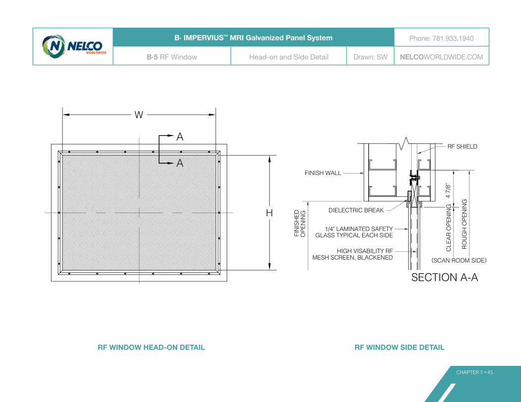
CHAPTER 1 • 45
4 7/
8"
ROU
GH
OPE
NIN
G
1/4" LAMINATED SAFETYGLASS TYPICAL EACH SIDE
RF SHIELD
DIELECTRIC BREAK
FIN
ISH
EDO
PEN
ING
FINISH WALL
(SCAN ROOM SIDE)HIGH VISABILITY RF
MESH SCREEN, BLACKENED
DRAWING NUMBER:PROPRIETARY NOTICE: THIS DOCUMENT AND THE INFORMATIONCONTAINED THEREIN IS PROPRIETARY AND COPYRIGHTED ANDMAY NOT BE ALTERED, COPIED, USED FOR MANUFACTURE, ORCOMMUNICATED TO ANY OTHER PERSON OR ENTITY WITHOUT THEWRITTEN CONSENT OF NELCO. ALL RIGHTS ARE RESERVED.
DATE:
ENG. MNG.:
DRAWN:
SCALE:
TITLE:
WWW.NELCOWORLDWIDE.COM
REVISIONS:
ELECTRONIC FILE:
CORPORATE HEADQUARTERS:2 BURLINGTON WOODS DRIVESUITE 300BURLINGTON, MA. 01803TEL: (800) 635-2613
SITE PLANING GUIDE
RF WINDOW GALVANIZEDPANEL SYSTEM
W
H
A
A
SECTION A-A
CLE
AR O
PEN
ING
RF WINDOW HEAD-ON DETAIL RF WINDOW SIDE DETAIL
B· IMPERVIUS™ MRI Galvanized Panel System Phone: 781.933.1940
B·5 RF Window Head-on and Side Detail Drawn: SW NELCOWORLDWIDE.COM
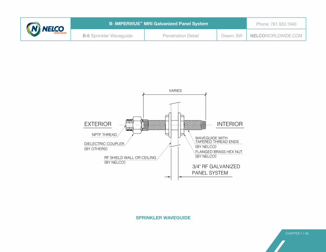
SPRINKLER WAVEGUIDE
CHAPTER 1 • 46
(BY NELCO)RF SHIELD WALL OR CEILING
NPTF THREAD
DIELECTRIC COUPLER(BY OTHERS)
VARIES
WAVEGUIDE WITH
(BY NELCO)FLANGED BRASS HEX NUT
TAPERED THREAD ENDS(BY NELCO)
INTERIOREXTERIOR
DRAWING NUMBER:PROPRIETARY NOTICE: THIS DOCUMENT AND THE INFORMATIONCONTAINED THEREIN IS PROPRIETARY AND COPYRIGHTED ANDMAY NOT BE ALTERED, COPIED, USED FOR MANUFACTURE, ORCOMMUNICATED TO ANY OTHER PERSON OR ENTITY WITHOUT THEWRITTEN CONSENT OF NELCO. ALL RIGHTS ARE RESERVED.
DATE:
ENG. MNG.:
DRAWN:
SCALE:
TITLE:
WWW.NELCOWORLDWIDE.COM
REVISIONS:
ELECTRONIC FILE:
CORPORATE HEADQUARTERS:2 BURLINGTON WOODS DRIVESUITE 300BURLINGTON, MA. 01803TEL: (800) 635-2613
SITE PLANING GUIDE
SPRINKLER PENETRATIONGALVANIZED PANELSYTEM
3/4" RF GALVANIZEDPANEL SYSTEM
B· IMPERVIUS™ MRI Galvanized Panel System Phone: 781.933.1940
B·6 Sprinkler Waveguide Penetration Detail Drawn: SW NELCOWORLDWIDE.COM

HVAC WAVEGUIDE
CHAPTER 1 • 47
ROU
GH
OPE
NIN
G
DU
CT
SIZE
FLEX DUCTCONNECTOR(BY OTHERS)
HVAC WAVE GUIDEPER SCHEDULE
4" M
IN.
PARENT WALL
3/4" GALVANIZEDPANEL SYSTEM
DUCT(BY OTHERS)
1/2" MAX. LENGTHSCREW
(INC
HES
OF
WAT
ER)
STAT
IC P
RESS
URE
DRO
P
1000800
900
600
700
.04
.05
.06
.00
.01
.02
.03
200
300
400
500
VELOCITY (FPM)
DRAWING NUMBER:PROPRIETARY NOTICE: THIS DOCUMENT AND THE INFORMATIONCONTAINED THEREIN IS PROPRIETARY AND COPYRIGHTED ANDMAY NOT BE ALTERED, COPIED, USED FOR MANUFACTURE, ORCOMMUNICATED TO ANY OTHER PERSON OR ENTITY WITHOUT THEWRITTEN CONSENT OF NELCO. ALL RIGHTS ARE RESERVED.
DATE:
ENG. MNG.:
DRAWN:
SCALE:
TITLE:
WWW.NELCOWORLDWIDE.COM
REVISIONS:
ELECTRONIC FILE:
CORPORATE HEADQUARTERS:2 BURLINGTON WOODS DRIVESUITE 300BURLINGTON, MA. 01803TEL: (800) 635-2613
SITE PLANING GUIDE
HVAC PENETRATIONGALVANIZED PANELSYSTEM
2 3/
4"2
3/4"
B· IMPERVIUS™ MRI Galvanized Panel System Phone: 781.933.1940
B·7 HVAC Waveguide Penetration Detail Drawn: SW NELCOWORLDWIDE.COM

MEDICAL GAS PIPE WAVEGUIDE
CHAPTER 1 • 48
(BY NELCO)RF SHIELD WALL OR CEILING
THROUGH PIPE(BY OTHERS)
LENGTH VARIES
WAVEGUIDE
(BY NELCO)BRASS HEX NUT
(BY NELCO)
INTERIOREXTERIOR RF SEAL(BY NELCO)
MEDICAL GAS PIPE WAVE GUIDE
(BY NELCO)GALVANIZED PANEL SYSTEM
DRAWING NUMBER:PROPRIETARY NOTICE: THIS DOCUMENT AND THE INFORMATIONCONTAINED THEREIN IS PROPRIETARY AND COPYRIGHTED ANDMAY NOT BE ALTERED, COPIED, USED FOR MANUFACTURE, ORCOMMUNICATED TO ANY OTHER PERSON OR ENTITY WITHOUT THEWRITTEN CONSENT OF NELCO. ALL RIGHTS ARE RESERVED.
DATE:
ENG. MNG.:
DRAWN:
SCALE:
TITLE:
WWW.NELCOWORLDWIDE.COM
REVISIONS:
ELECTRONIC FILE:
CORPORATE HEADQUARTERS:2 BURLINGTON WOODS DRIVESUITE 300BURLINGTON, MA. 01803TEL: (800) 635-2613
SITE PLANING GUIDE
MEDICAL GAS PIPEPENETRATION GALVANIZEDPANEL SYSTEM
B· IMPERVIUS™ MRI Galvanized Panel System Phone: 781.933.1940
B·8 Medical Gas Waveguide Gas Pipe Penetration Detail Drawn: SW NELCOWORLDWIDE.COM

CHAPTER 1 • 49
EQ.
A
A
VIEW A-A
6"
6"
EQ.
NON-FERROUS THROUGHACCESSORY
ALUMINUM OR COPPERPIPE, DIAMETER VARIES
MOUNTING PLATE
3/4" GALVANIZEDPANEL SYSTEM
DRAWING NUMBER:PROPRIETARY NOTICE: THIS DOCUMENT AND THE INFORMATIONCONTAINED THEREIN IS PROPRIETARY AND COPYRIGHTED ANDMAY NOT BE ALTERED, COPIED, USED FOR MANUFACTURE, ORCOMMUNICATED TO ANY OTHER PERSON OR ENTITY WITHOUT THEWRITTEN CONSENT OF NELCO. ALL RIGHTS ARE RESERVED.
DATE:
ENG. MNG.:
DRAWN:
SCALE:
TITLE:
WWW.NELCOWORLDWIDE.COM
REVISIONS:
ELECTRONIC FILE:
CORPORATE HEADQUARTERS:2 BURLINGTON WOODS DRIVESUITE 300BURLINGTON, MA. 01803TEL: (800) 635-2613
SITE PLANING GUIDE
ACCESSORY PIPEPENETRATION GALVANIZEDPANEL SYSTEM
MIN. 4X DIAMETERLENGTH VARIES
EQ.
A
A
VIEW A-A
6"
6"
EQ.
NON-FERROUS THROUGHACCESSORY
ALUMINUM OR COPPERPIPE, DIAMETER VARIES
MOUNTING PLATE
3/4" GALVANIZEDPANEL SYSTEM
DRAWING NUMBER:PROPRIETARY NOTICE: THIS DOCUMENT AND THE INFORMATIONCONTAINED THEREIN IS PROPRIETARY AND COPYRIGHTED ANDMAY NOT BE ALTERED, COPIED, USED FOR MANUFACTURE, ORCOMMUNICATED TO ANY OTHER PERSON OR ENTITY WITHOUT THEWRITTEN CONSENT OF NELCO. ALL RIGHTS ARE RESERVED.
DATE:
ENG. MNG.:
DRAWN:
SCALE:
TITLE:
WWW.NELCOWORLDWIDE.COM
REVISIONS:
ELECTRONIC FILE:
CORPORATE HEADQUARTERS:2 BURLINGTON WOODS DRIVESUITE 300BURLINGTON, MA. 01803TEL: (800) 635-2613
SITE PLANING GUIDE
ACCESSORY PIPEPENETRATION GALVANIZEDPANEL SYSTEM
MIN. 4X DIAMETERLENGTH VARIES
WAVEGUIDE FEEDTHROUGH
B· IMPERVIUS™ MRI Galvanized Panel System Phone: 781.933.1940
B·9 Waveguide Feedthrough Accessory Pipe Penetration Detail Drawn: SW NELCOWORLDWIDE.COM

WALL SECTION (WALL/CEILING)
CHAPTER 1 • 50
PARENTWALL
3/4" PLYWOOD SHEATHINGWITH SOLDER COPPER RF SHIELDING
SCREW TOP PLATE/STUD TRACK TO WOODBATTEN. DO NOT PENETRATE THROUGHBATTEN SYSTEM (BY OTHERS)
3/4" PARENT WALL ISOLATION GAP
SOLDERED COPPERRF SHIELD
INTERIOR DRYWALL PARTITION(BY OTHERS)
3/4" PLYWOOD
CEILING SUPPORTSYSTEM
RF BATTEN
ISOLATION BATTEN 3/4"PLYWOOOD
DRAWING NUMBER:PROPRIETARY NOTICE: THIS DOCUMENT AND THE INFORMATIONCONTAINED THEREIN IS PROPRIETARY AND COPYRIGHTED ANDMAY NOT BE ALTERED, COPIED, USED FOR MANUFACTURE, ORCOMMUNICATED TO ANY OTHER PERSON OR ENTITY WITHOUT THEWRITTEN CONSENT OF NELCO. ALL RIGHTS ARE RESERVED.
DATE:
ENG. MNG.:
DRAWN:
SCALE:
TITLE:
WWW.NELCOWORLDWIDE.COM
REVISIONS:
ELECTRONIC FILE:
CORPORATE HEADQUARTERS:2 BURLINGTON WOODS DRIVESUITE 300BURLINGTON, MA. 01803TEL: (800) 635-2613
SITE PLANING GUIDE
CEILING TO WALLTRANSITION SOLDEREDCOPPER SYSTEM
C· IMPERVIUS™ MRI Soldered Copper System Phone: 781.933.1940
C·1 Wall Section (Wall/Ceiling) Ceiling-to-Wall Transition Drawn: SW NELCOWORLDWIDE.COM

FLOOR SECTION (PANEL FLOOR SYSTEM)
CHAPTER 1 • 51
SCREW BOTTOM PLATE/STUD TRACK TOFLOOR PANEL. DO NOT PENETRATETHROUGH COPPER SHIELD.
(1) LAYER 1/8" DIELECTRIC MATERIAL
SOLDERED COPPER
(2) LAYERS CEMENT BOARDTOTAL 3/4" THICKNESS
VAPOR BARRIER
LEVELING COMPOUNDFINISHED FLOOR
1" INTERIOR WALL GAP
INTERIOR STUD AND DRYWALL FINISH
ISOLATION BATTEN 3/4" PLYWOOOD
3/4" PLYWOOD SHEATHINGW/SOLDER COPPER RF SHIELDING
DEP
RESS
ION
DRAWING NUMBER:PROPRIETARY NOTICE: THIS DOCUMENT AND THE INFORMATIONCONTAINED THEREIN IS PROPRIETARY AND COPYRIGHTED ANDMAY NOT BE ALTERED, COPIED, USED FOR MANUFACTURE, ORCOMMUNICATED TO ANY OTHER PERSON OR ENTITY WITHOUT THEWRITTEN CONSENT OF NELCO. ALL RIGHTS ARE RESERVED.
DATE:
ENG. MNG.:
DRAWN:
SCALE:
TITLE:
WWW.NELCOWORLDWIDE.COM
REVISIONS:
ELECTRONIC FILE:
CORPORATE HEADQUARTERS:2 BURLINGTON WOODS DRIVESUITE 300BURLINGTON, MA. 01803TEL: (800) 635-2613
SITE PLANING GUIDE
WALL TO FLOORTRANSITIONS SOLDERCOPPER SYSTEM
PARENT
SLAB
WALL
C· IMPERVIUS™ MRI Soldered Copper System Phone: 781.933.1940
C·2 Floor Section (Panel Floor System) Wall-to-Floor Transition Drawn: SW NELCOWORLDWIDE.COM

CHAPTER 1 • 52
RF DOOR HEAD DETAIL(SIMILAR AT JAMBS)
RF DOOR SILL DETAIL
RF FRAMERF DOOR
SOLDERED COPPERRF SHIELD
DRAWING NUMBER:PROPRIETARY NOTICE: THIS DOCUMENT AND THE INFORMATIONCONTAINED THEREIN IS PROPRIETARY AND COPYRIGHTED ANDMAY NOT BE ALTERED, COPIED, USED FOR MANUFACTURE, ORCOMMUNICATED TO ANY OTHER PERSON OR ENTITY WITHOUT THEWRITTEN CONSENT OF NELCO. ALL RIGHTS ARE RESERVED.
DATE:
ENG. MNG.:
DRAWN:
SCALE:
TITLE:
WWW.NELCOWORLDWIDE.COM
REVISIONS:
ELECTRONIC FILE:
CORPORATE HEADQUARTERS:2 BURLINGTON WOODS DRIVESUITE 300BURLINGTON, MA. 01803TEL: (800) 635-2613
SITE PLANING GUIDE
RF DOOR OUT SWINGSOLDERED COPPERSYSTEM
RF DOOR SILL
3/8"
DEP
RESS
ION
*
*DEPRESSION TO EXTEND 4" FROM OUTSIDEFACE OF SHIELD INTO ADJACENT ROOM.
RF DOOR SILL DETAIL
FINISHFLOOR
RF F
LOO
RAS
SEM
BLY
(SCAN ROOM SIDE)
RF DOOR HEAD DETAIL(SIMILAR AT JAMBS)
FINISH(BY OTHERS)
(SCAN ROOM SIDE)
RF DOOR RF DOOR FRAME
3/4" PLYWOOD
ISOLATION BATTEN
3/4" PLYWOOD
C· IMPERVIUS™ MRI Soldered Copper System Phone: 781.933.1940
C·3 RF Door – Outswing Outswing Door Head and Sill Drawn: SW NELCOWORLDWIDE.COM

CHAPTER 1 • 53
RF DOOR HEAD DETAIL(SIMILAR AT JAMBS)
RF DOOR SILL DETAIL
RF FRAME RF DOOR
SOLDERED COPPER RF SHIELD
DRAWING NUMBER:PROPRIETARY NOTICE: THIS DOCUMENT AND THE INFORMATIONCONTAINED THEREIN IS PROPRIETARY AND COPYRIGHTED ANDMAY NOT BE ALTERED, COPIED, USED FOR MANUFACTURE, ORCOMMUNICATED TO ANY OTHER PERSON OR ENTITY WITHOUT THEWRITTEN CONSENT OF NELCO. ALL RIGHTS ARE RESERVED.
DATE:
ENG. MNG.:
DRAWN:
SCALE:
TITLE:
WWW.NELCOWORLDWIDE.COM
REVISIONS:
ELECTRONIC FILE:
CORPORATE HEADQUARTERS:2 BURLINGTON WOODS DRIVESUITE 300BURLINGTON, MA. 01803TEL: (800) 635-2613
SITE PLANING GUIDE
RF DOOR IN SWINGSOLDERED COPPERSYSTEM
RF DOOR SILL
3/8"
DEP
RESS
ION
*
*DEPRESSION TO EXTEND 4" FROM OUTSIDEFACE OF SHIELD INTO ADJACENT ROOM.
RF DOOR SILL DETAIL
FINISHFLOOR RF
FLO
OR
ASSE
MBL
Y
(SCAN ROOM SIDE)
RF DOOR HEAD DETAIL(SIMILAR AT JAMBS)
FINISH(BY OTHERS)
(SCAN ROOM SIDE)
RF DOORRF DOOR FRAME
3/4" PLYWOOD
ISOLATIONBATTEN
3/4" PLYWOOD
RF FRAME RF DOOR
SOLDERED COPPER RF SHIELD
DRAWING NUMBER:PROPRIETARY NOTICE: THIS DOCUMENT AND THE INFORMATIONCONTAINED THEREIN IS PROPRIETARY AND COPYRIGHTED ANDMAY NOT BE ALTERED, COPIED, USED FOR MANUFACTURE, ORCOMMUNICATED TO ANY OTHER PERSON OR ENTITY WITHOUT THEWRITTEN CONSENT OF NELCO. ALL RIGHTS ARE RESERVED.
DATE:
ENG. MNG.:
DRAWN:
SCALE:
TITLE:
WWW.NELCOWORLDWIDE.COM
REVISIONS:
ELECTRONIC FILE:
CORPORATE HEADQUARTERS:2 BURLINGTON WOODS DRIVESUITE 300BURLINGTON, MA. 01803TEL: (800) 635-2613
SITE PLANING GUIDE
RF DOOR IN SWINGSOLDERED COPPERSYSTEM
RF DOOR SILL
3/8"
DEP
RESS
ION
*
*DEPRESSION TO EXTEND 4" FROM OUTSIDEFACE OF SHIELD INTO ADJACENT ROOM.
RF DOOR SILL DETAIL
FINISHFLOOR RF
FLO
OR
ASSE
MBL
Y
(SCAN ROOM SIDE)
RF DOOR HEAD DETAIL(SIMILAR AT JAMBS)
FINISH(BY OTHERS)
(SCAN ROOM SIDE)
RF DOORRF DOOR FRAME
3/4" PLYWOOD
ISOLATIONBATTEN
3/4" PLYWOODC· IMPERVIUS™ MRI Soldered Copper System Phone: 781.933.1940
C·4 RF Door – Inswing Inswing Door Head and Sill Drawn: SW NELCOWORLDWIDE.COM
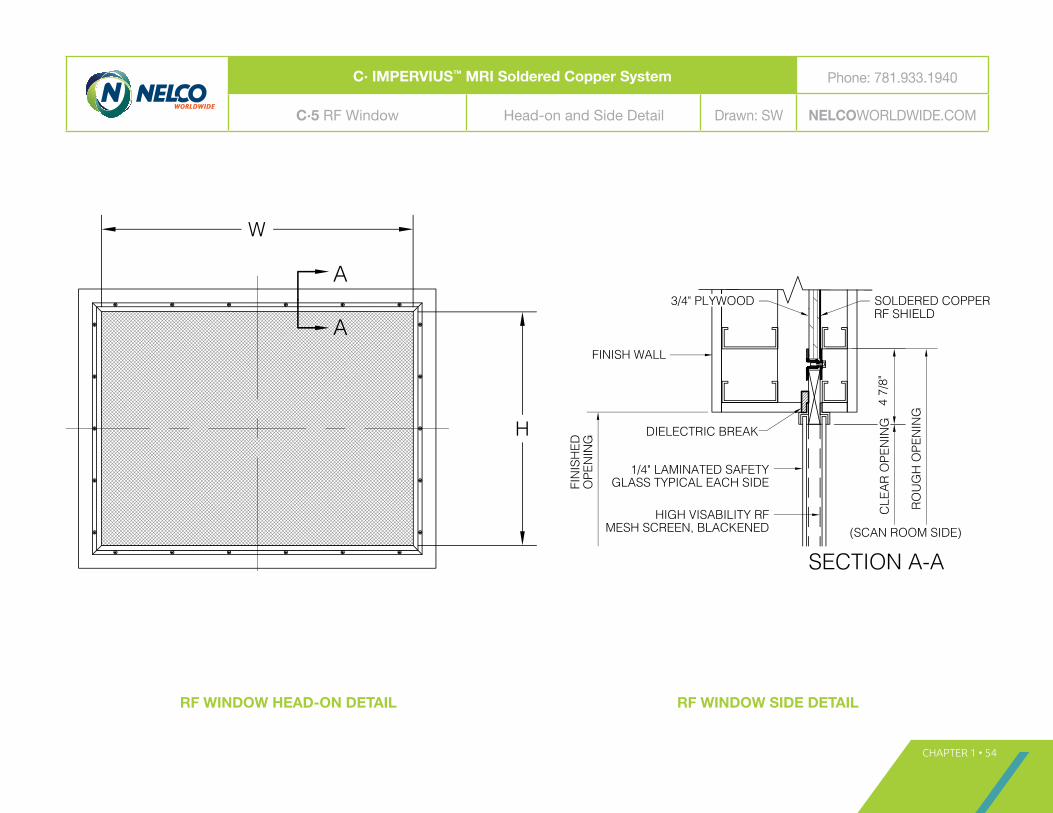
RF WINDOW HEAD-ON DETAIL RF WINDOW SIDE DETAIL
CHAPTER 1 • 54
4 7/
8"
ROU
GH
OPE
NIN
G
1/4" LAMINATED SAFETYGLASS TYPICAL EACH SIDE
SOLDERED COPPERRF SHIELD
DIELECTRIC BREAK
FIN
ISH
EDO
PEN
ING
FINISH WALL
(SCAN ROOM SIDE)HIGH VISABILITY RF
MESH SCREEN, BLACKENED
3/4" PLYWOOD
DRAWING NUMBER:PROPRIETARY NOTICE: THIS DOCUMENT AND THE INFORMATIONCONTAINED THEREIN IS PROPRIETARY AND COPYRIGHTED ANDMAY NOT BE ALTERED, COPIED, USED FOR MANUFACTURE, ORCOMMUNICATED TO ANY OTHER PERSON OR ENTITY WITHOUT THEWRITTEN CONSENT OF NELCO. ALL RIGHTS ARE RESERVED.
DATE:
ENG. MNG.:
DRAWN:
SCALE:
TITLE:
WWW.NELCOWORLDWIDE.COM
REVISIONS:
ELECTRONIC FILE:
CORPORATE HEADQUARTERS:2 BURLINGTON WOODS DRIVESUITE 300BURLINGTON, MA. 01803TEL: (800) 635-2613
SITE PLANING GUIDE
RF WINDOW SOLDEREDCOPPER SYSTEM
W
H
A
A
SECTION A-A
CLE
AR O
PEN
ING
C· IMPERVIUS™ MRI Soldered Copper System Phone: 781.933.1940
C·5 RF Window Head-on and Side Detail Drawn: SW NELCOWORLDWIDE.COM

SPRINKLER WAVEGUIDE
CHAPTER 1 • 55
(BY NELCO)RF SHIELD WALL OR CEILING
NPTF THREAD
DIELECTRIC COUPLER(BY OTHERS)
VARIES
WAVEGUIDE WITH
(BY NELCO)FLANGED BRASS HEX NUT
TAPERED THREAD ENDS(BY NELCO)
INTERIOREXTERIOR
3/4" PLYWOOD SOLDERED COPPER SHIELD
DRAWING NUMBER:PROPRIETARY NOTICE: THIS DOCUMENT AND THE INFORMATIONCONTAINED THEREIN IS PROPRIETARY AND COPYRIGHTED ANDMAY NOT BE ALTERED, COPIED, USED FOR MANUFACTURE, ORCOMMUNICATED TO ANY OTHER PERSON OR ENTITY WITHOUT THEWRITTEN CONSENT OF NELCO. ALL RIGHTS ARE RESERVED.
DATE:
ENG. MNG.:
DRAWN:
SCALE:
TITLE:
WWW.NELCOWORLDWIDE.COM
REVISIONS:
ELECTRONIC FILE:
CORPORATE HEADQUARTERS:2 BURLINGTON WOODS DRIVESUITE 300BURLINGTON, MA. 01803TEL: (800) 635-2613
SITE PLANING GUIDE
SPRINKLER PENETRATIONSOLDER COPPER SYSTEM
3/4"
C· IMPERVIUS™ MRI Soldered Copper System Phone: 781.933.1940
C·6 Sprinkler Waveguide Penetration Detail Drawn: SW NELCOWORLDWIDE.COM

HVAC WAVEGUIDE
CHAPTER 1 • 56
ROU
GH
OPE
NIN
G
DU
CT
SIZE
2 3/
4"2
7/8"
FLEX DUCTCONNECTOR(BY OTHERS)
4" M
IN.
PARENT WALL3/4" PLYWOOD
DUCT(BY OTHERS)
1/2" MAX. LENGTHSCREW
HVAC WAVE GUIDEPER SCHEDULE
SOLDERED COPPER(IN
CH
ES O
F W
ATER
)ST
ATIC
PRE
SSU
RE D
ROP
1000800
900
600
700
.04
.05
.06
.00
.01
.02
.03
200
300
400
500
VELOCITY (FPM)
DRAWING NUMBER:PROPRIETARY NOTICE: THIS DOCUMENT AND THE INFORMATIONCONTAINED THEREIN IS PROPRIETARY AND COPYRIGHTED ANDMAY NOT BE ALTERED, COPIED, USED FOR MANUFACTURE, ORCOMMUNICATED TO ANY OTHER PERSON OR ENTITY WITHOUT THEWRITTEN CONSENT OF NELCO. ALL RIGHTS ARE RESERVED.
DATE:
ENG. MNG.:
DRAWN:
SCALE:
TITLE:
WWW.NELCOWORLDWIDE.COM
REVISIONS:
ELECTRONIC FILE:
CORPORATE HEADQUARTERS:2 BURLINGTON WOODS DRIVESUITE 300BURLINGTON, MA. 01803TEL: (800) 635-2613
SITE PLANING GUIDE
HVAC PENETRATIONGALVANIZED PANELSYSTEM
ROU
GH
OPE
NIN
G
DU
CT
SIZE
2 3/
4"2
7/8"
FLEX DUCTCONNECTOR(BY OTHERS)
4" M
IN.
PARENT WALL3/4" PLYWOOD
DUCT(BY OTHERS)
1/2" MAX. LENGTHSCREW
HVAC WAVE GUIDEPER SCHEDULE
SOLDERED COPPER
(INC
HES
OF
WAT
ER)
STAT
IC P
RESS
URE
DRO
P
1000800
900
600
700
.04
.05
.06
.00
.01
.02
.03
200
300
400
500
VELOCITY (FPM)
DRAWING NUMBER:PROPRIETARY NOTICE: THIS DOCUMENT AND THE INFORMATIONCONTAINED THEREIN IS PROPRIETARY AND COPYRIGHTED ANDMAY NOT BE ALTERED, COPIED, USED FOR MANUFACTURE, ORCOMMUNICATED TO ANY OTHER PERSON OR ENTITY WITHOUT THEWRITTEN CONSENT OF NELCO. ALL RIGHTS ARE RESERVED.
DATE:
ENG. MNG.:
DRAWN:
SCALE:
TITLE:
WWW.NELCOWORLDWIDE.COM
REVISIONS:
ELECTRONIC FILE:
CORPORATE HEADQUARTERS:2 BURLINGTON WOODS DRIVESUITE 300BURLINGTON, MA. 01803TEL: (800) 635-2613
SITE PLANING GUIDE
HVAC PENETRATIONGALVANIZED PANELSYSTEM
C· IMPERVIUS™ MRI Soldered Copper System Phone: 781.933.1940
C·7 HVAC Waveguide Penetration Detail Drawn: SW NELCOWORLDWIDE.COM

MEDICAL GAS PIPE WAVEGUIDE
CHAPTER 1 • 57
(BY NELCO)RF SHIELD WALL OR CEILING
THROUGH PIPE(BY OTHERS)
LENGTH VARIES
WAVEGUIDE
(BY NELCO)BRASS HEX NUT
(BY NELCO)
INTERIOREXTERIOR RF SEAL(BY NELCO)
MEDICAL GAS PIPE WAVE GUIDE
3/4" PLYWOOD SOLDERED COPPER RF SHIELD
DRAWING NUMBER:PROPRIETARY NOTICE: THIS DOCUMENT AND THE INFORMATIONCONTAINED THEREIN IS PROPRIETARY AND COPYRIGHTED ANDMAY NOT BE ALTERED, COPIED, USED FOR MANUFACTURE, ORCOMMUNICATED TO ANY OTHER PERSON OR ENTITY WITHOUT THEWRITTEN CONSENT OF NELCO. ALL RIGHTS ARE RESERVED.
DATE:
ENG. MNG.:
DRAWN:
SCALE:
TITLE:
WWW.NELCOWORLDWIDE.COM
REVISIONS:
ELECTRONIC FILE:
CORPORATE HEADQUARTERS:2 BURLINGTON WOODS DRIVESUITE 300BURLINGTON, MA. 01803TEL: (800) 635-2613
SITE PLANING GUIDE
MEDICAL GAS PIPEPENETRATION SOLDEREDCOPPER SYSTEM
C· IMPERVIUS™ MRI Soldered Copper System Phone: 781.933.1940
C·8 Medical Gas Waveguide Gas Pipe Penetration Detail Drawn: SW NELCOWORLDWIDE.COM

CHAPTER 1 • 58
EQ.
A
A
VIEW A-A
6"
6"
EQ.
NON-FERROUS THROUGHACCESSORY
ALUMINUM OR COPPERPIPE, DIAMETER VARIES
MOUNTING PLATE
3/4" PLYWOODSOLDEREDCOPPER
MIN. 4X DIAMETERLENGTH VARIES
DRAWING NUMBER:PROPRIETARY NOTICE: THIS DOCUMENT AND THE INFORMATIONCONTAINED THEREIN IS PROPRIETARY AND COPYRIGHTED ANDMAY NOT BE ALTERED, COPIED, USED FOR MANUFACTURE, ORCOMMUNICATED TO ANY OTHER PERSON OR ENTITY WITHOUT THEWRITTEN CONSENT OF NELCO. ALL RIGHTS ARE RESERVED.
DATE:
ENG. MNG.:
DRAWN:
SCALE:
TITLE:
WWW.NELCOWORLDWIDE.COM
REVISIONS:
ELECTRONIC FILE:
CORPORATE HEADQUARTERS:2 BURLINGTON WOODS DRIVESUITE 300BURLINGTON, MA. 01803TEL: (800) 635-2613
SITE PLANING GUIDE
ACCESSORY PIPEPENETRATION SOLDEREDCOPPER SYSTEM
EQ.
A
A
VIEW A-A
6"
6"
EQ.
NON-FERROUS THROUGHACCESSORY
ALUMINUM OR COPPERPIPE, DIAMETER VARIES
MOUNTING PLATE
3/4" PLYWOODSOLDEREDCOPPER
MIN. 4X DIAMETERLENGTH VARIES
DRAWING NUMBER:PROPRIETARY NOTICE: THIS DOCUMENT AND THE INFORMATIONCONTAINED THEREIN IS PROPRIETARY AND COPYRIGHTED ANDMAY NOT BE ALTERED, COPIED, USED FOR MANUFACTURE, ORCOMMUNICATED TO ANY OTHER PERSON OR ENTITY WITHOUT THEWRITTEN CONSENT OF NELCO. ALL RIGHTS ARE RESERVED.
DATE:
ENG. MNG.:
DRAWN:
SCALE:
TITLE:
WWW.NELCOWORLDWIDE.COM
REVISIONS:
ELECTRONIC FILE:
CORPORATE HEADQUARTERS:2 BURLINGTON WOODS DRIVESUITE 300BURLINGTON, MA. 01803TEL: (800) 635-2613
SITE PLANING GUIDE
ACCESSORY PIPEPENETRATION SOLDEREDCOPPER SYSTEM
WAVEGUIDE FEEDTHROUGH
C· IMPERVIUS™ MRI Soldered Copper System Phone: 781.933.1940
C·9 Waveguide Feedthrough Accessory Pipe Penetration Detail Drawn: SW NELCOWORLDWIDE.COM

060119
Phone: 781.933.1940 NELCOWORLDWIDE.COM