mq system light & project - hilti system light & project ... mqz-p9 2141908 mqz-p11 2141909...
TRANSCRIPT
1
MQ System Light & Project
Installation Technical Manual - Technical Data - MQ system light & project
Boundary conditions - Terms of common cooperation / Legal disclaimer and guidelines as defined at the beginning of this book need to be mandatorily respected.
Data version 1.1 I Date 02.2017
Installation Technical Manual
Technical data
MQ System Light & Project
Version 1.1 I 02.2017
2
MQ System Light & Project
Installation Technical Manual - Technical Data - MQ system light & project
Boundary conditions - Terms of common cooperation / Legal disclaimer and guidelines as defined at the beginning of this book need to be mandatorily respected.
Data version 1.1 I Date 02.2017
Terms of common cooperation /Legal disclaimerThe product loading capacities published in these Technical Data Sheets are only valid for the mentioned codes or technical data generation methods and the defined application conditions (e.g. ambient temperature load capacity not valid in case of fire, data not valid in support structures when mixed with third party products), assuming sufficient fastener, base material and building structure strength. Additional calculations, checks and releases by the responsible structural engineer might be needed to clarify the capacity of base material and building structure. Suitability of structures combining different products for specific applications needs to be verified by conducting a system design and calculation, using for example Hilti PROFIS software. In addition, it is crucial to fully respect the Instructions for Use and to assure clean, unaltered and undamaged state of all products at any time in order to achieve this loading capacity (e.g. misuse, modification, overload, corrosion).As products but also technical data generation methodologies evolve over time, technical data might change at any time without prior notice. We recommend to use the latest technical data sheets published by Hilti.
In any case the suitability of structures combining different products for specific applications need to be checked and cleared by an expert, particularly with regard to compliance with applicable norms and permits, prior to using them for any specific facility. This book only serves as an aid to interpret the suitability of structures combining different products for specific applications without any guarantee as to the absence of errors, the correctness and the relevance of the results or suitability for a specific application. User must take all necessary and reasonable steps to prevent or limit damage. The suitability of structures combining different products for specific applications are only recommendations that need to be confirmed with a professional designer and/or structural engineers to ensure compliance with User`s specific jurisdiction and project requirements.
3
MQ System Light & Project
Installation Technical Manual - Technical Data - MQ system light & project
Boundary conditions - Terms of common cooperation / Legal disclaimer and guidelines as defined at the beginning of this book need to be mandatorily respected.
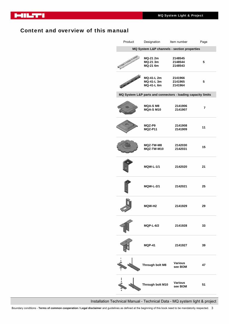
Content and overview of this manual
Product Designation Item number Page
MQ System L&P channels - section properties
MQ-21 2mMQ-21 3mMQ-21 6m
214854521485442148543
5
MQ-41-L 2mMQ-41-L 3mMQ-41-L 6m
214196621419652141964
5
MQ System L&P parts and connectors - loading capacity limits
MQA-S M8MQA-S M10
21419062141907
7
MQZ-P9MQZ-P11
21419082141909
11
MQZ-TW-M8MQZ-TW-M10
21420302142031
15
MQW-L-1/1 2142020 21
MQW-L-2/1 2142021 25
MQW-H2 2141929 29
MQP-L-6/2 2141928 33
MQP-41 2141927 39
Through bolt M8Various see BOM
47
Through bolt M10Various see BOM
51
4
MQ System Light & Project
Installation Technical Manual - Technical Data - MQ system light & project
Boundary conditions - Terms of common cooperation / Legal disclaimer and guidelines as defined at the beginning of this book need to be mandatorily respected.
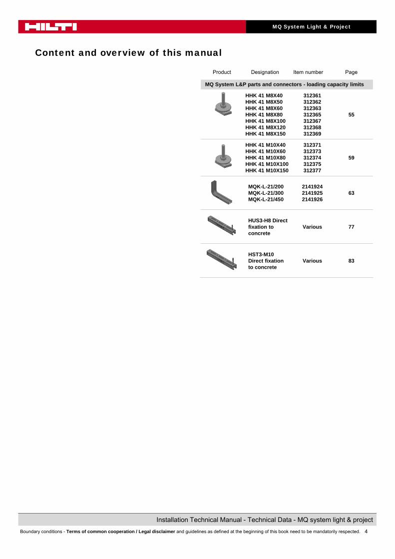
Content and overview of this manual
Product Designation Item number Page
MQ System L&P parts and connectors - loading capacity limits
HHK 41 M8X40 HHK 41 M8X50 HHK 41 M8X60 HHK 41 M8X80 HHK 41 M8X100 HHK 41 M8X120 HHK 41 M8X150
312361312362312363312365312367312368312369
55
HHK 41 M10X40 HHK 41 M10X60 HHK 41 M10X80 HHK 41 M10X100 HHK 41 M10X150
312371312373312374312375312377
59
MQK-L-21/200MQK-L-21/300MQK-L-21/450
214192421419252141926
63
HUS3-H8 Direct fixation to concrete
Various 77
HST3-M10 Direct fixation to concrete
Various 83
5
MQ System Light & Project
Installation Technical Manual - Technical Data - MQ system light & project
Boundary conditions - Terms of common cooperation / Legal disclaimer and guidelines as defined at the beginning of this book need to be mandatorily respected.
Data version 1.1 I Date 02.2017
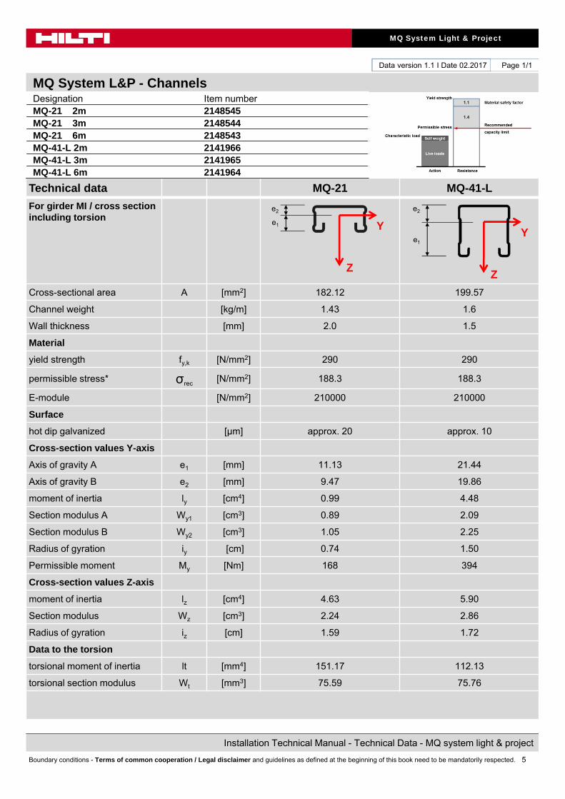
MQ System L&P - Channels
Technical data MQ-21 MQ-41-L
For girder MI / cross section including torsion
Cross-sectional area A [mm2] 182.12 199.57
Channel weight [kg/m] 1.43 1.6
Wall thickness [mm] 2.0 1.5
Material
yield strength fy,k [N/mm2] 290 290
permissible stress* σrec[N/mm2] 188.3 188.3
E-module [N/mm2] 210000 210000
Surface
hot dip galvanized [μm] approx. 20 approx. 10
Cross-section values Y-axis
Axis of gravity A e1 [mm] 11.13 21.44
Axis of gravity B e2 [mm] 9.47 19.86
moment of inertia ly [cm4] 0.99 4.48
Section modulus A Wy1 [cm3] 0.89 2.09
Section modulus B Wy2 [cm3] 1.05 2.25
Radius of gyration iy [cm] 0.74 1.50
Permissible moment My [Nm] 168 394
Cross-section values Z-axis
moment of inertia lz [cm4] 4.63 5.90
Section modulus Wz [cm3] 2.24 2.86
Radius of gyration iz [cm] 1.59 1.72
Data to the torsion
torsional moment of inertia lt [mm4] 151.17 112.13
torsional section modulus Wt [mm3] 75.59 75.76
Z
Y
Page 1/1
Designation Item numberMQ-21 2m 2148545MQ-21 3m 2148544MQ-21 6m 2148543MQ-41-L 2m 2141966MQ-41-L 3m 2141965MQ-41-L 6m 2141964
Z
Y
e2
e1
e2
e1
6
MQ System Light & Project
Installation Technical Manual - Technical Data - MQ system light & project
Boundary conditions - Terms of common cooperation / Legal disclaimer and guidelines as defined at the beginning of this book need to be mandatorily respected.
7
MQ System Light & Project
Installation Technical Manual - Technical Data - MQ system light & project
Boundary conditions - Terms of common cooperation / Legal disclaimer and guidelines as defined at the beginning of this book need to be mandatorily respected.
Data version 1.1 I Date 02.2017
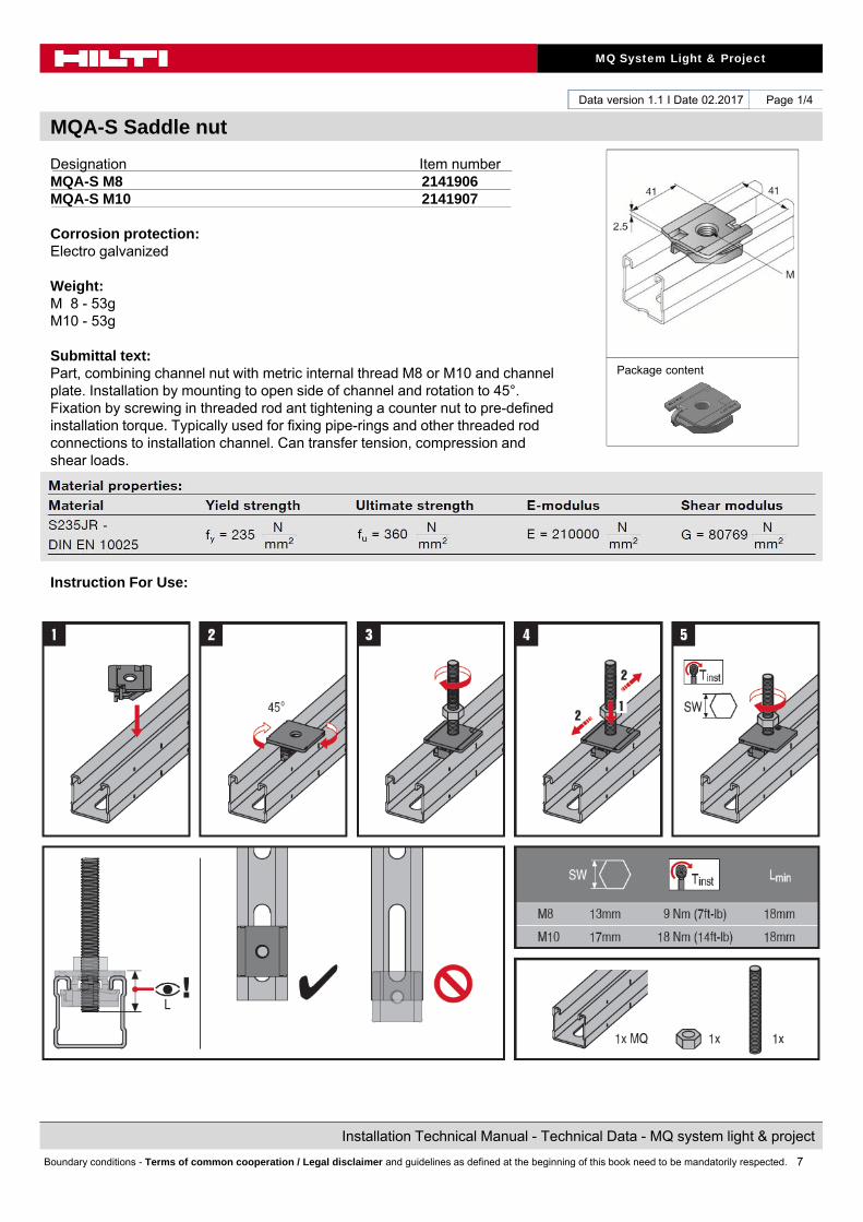
MQA-S Saddle nut
Page 1/4
Designation Item numberMQA-S M8 2141906MQA-S M10 2141907
Corrosion protection:Electro galvanized
Weight:M 8 - 53gM10 - 53g
Submittal text:Part, combining channel nut with metric internal thread M8 or M10 and channel plate. Installation by mounting to open side of channel and rotation to 45°. Fixation by screwing in threaded rod ant tightening a counter nut to pre-defined installation torque. Typically used for fixing pipe-rings and other threaded rod connections to installation channel. Can transfer tension, compression and shear loads.
Instruction For Use:
Package content

8
MQ System Light & Project
Installation Technical Manual - Technical Data - MQ system light & project
Boundary conditions - Terms of common cooperation / Legal disclaimer and guidelines as defined at the beginning of this book need to be mandatorily respected.
Data version 1.1 I Date 02.2017
MQA-S Saddle nut
Page 2/4
Possible loading cases
Standard
Design criteria used for loading capacity
Methodology:• Finite element analysis
Standards and codes:• EN 1990 Basics of structural design 03.2003• EN 1991-1-1 Eurocode 1: Actions on structures – Part 1-1: General
actions – densities, self-weight, imposed loads for buildings 09.2011• EN 1993-1-1 Eurocode 3: Design of steel structures – Part 1-1: General
rules and rules for buildings 03.2012• EN 1993-1-3 Eurocode 3: Design of steel structures – Part 1-3: General
rules- Supplementary rules for cold-formed members andsheeting 03.2012
• EN 1993-1-5 Eurocode 3: Design of steel structures – Part 1-5: Platedstructural elements 03.2012
• EN 1993-1-8 Eurocode 3: Design of steel structures – Part 1-8: Design ofjoints 03.2012
EN 10025-2 Hot rolled products of structural steels- Part 2: technicaldelivery conditions for non-alloy structural steels 02.2005
• RAL-GZ 655 Pipe Supports 04.2008
Software: • Ansys 16.0• Microsoft Excel
Environmental conditions: • static loads• no fatigue loads
Simplified drawing:
9
MQ System Light & Project
Installation Technical Manual - Technical Data - MQ system light & project
Boundary conditions - Terms of common cooperation / Legal disclaimer and guidelines as defined at the beginning of this book need to be mandatorily respected.
Data version 1.1 I Date 02.2017
MQA-S Saddle nut
Page 3/4
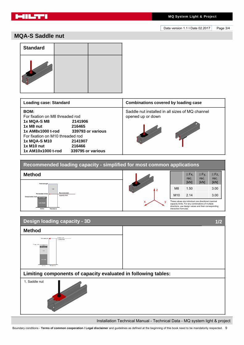
Standard
Loading case: Standard Combinations covered by loading case
BOM:For fixation on M8 threaded rod1x MQA-S M8 21419061x M8 nut 2164651x AM8x1000 t-rod 339793 or variousFor fixation on M10 threaded rod1x MQA-S M10 21419071x M10 nut 2164661x AM10x1000 t-rod 339795 or various
Saddle nut installed in all sizes of MQ channel opened up or down
Recommended loading capacity - simplified for most common applications
Method
Design loading capacity - 3D
Method
Limiting components of capacity evaluated in following tables:
1. Saddle nut
±Fx,rec. [kN]
±Fy,rec. [kN]
±Fz,rec. [kN]
M8 1.50 3.00
M10 2.14 3.00
These values are individual one directional maximal capacity limits. For any combinations of multiple directions, use design values and their corresponding interaction formulas.
1/2
z
yx
10
MQ System Light & Project
Installation Technical Manual - Technical Data - MQ system light & project
Boundary conditions - Terms of common cooperation / Legal disclaimer and guidelines as defined at the beginning of this book need to be mandatorily respected.
Data version 1.1 I Date 02.2017
MQA-S Saddle nut
Page 4/4
Standard
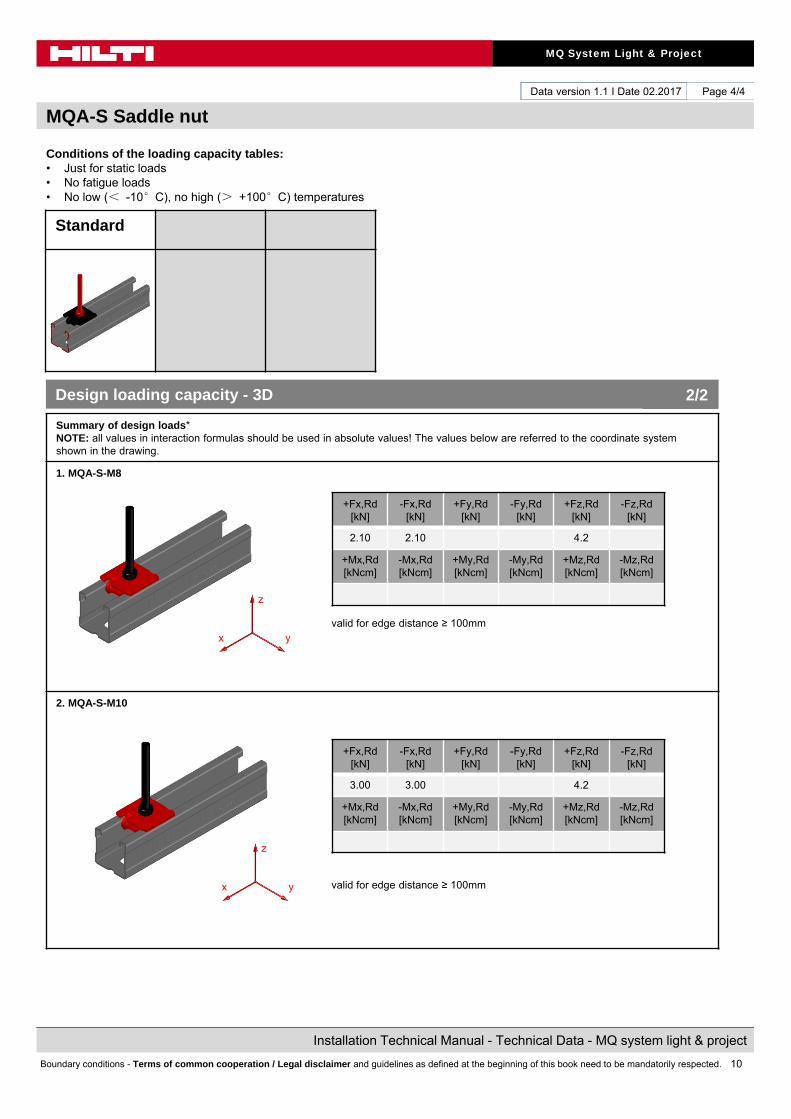
Conditions of the loading capacity tables:• Just for static loads• No fatigue loads• No low (< -10°C), no high (> +100°C) temperatures
Summary of design loads*NOTE: all values in interaction formulas should be used in absolute values! The values below are referred to the coordinate system shown in the drawing.
1. MQA-S-M8
valid for edge distance ≥ 100mm
2. MQA-S-M10
valid for edge distance ≥ 100mm
+Fx,Rd[kN]
-Fx,Rd[kN]
+Fy,Rd[kN]
-Fy,Rd[kN]
+Fz,Rd[kN]
-Fz,Rd[kN]
2.10 2.10 4.2
+Mx,Rd[kNcm]
-Mx,Rd[kNcm]
+My,Rd[kNcm]
-My,Rd[kNcm]
+Mz,Rd[kNcm]
-Mz,Rd[kNcm]
+Fx,Rd[kN]
-Fx,Rd[kN]
+Fy,Rd[kN]
-Fy,Rd[kN]
+Fz,Rd[kN]
-Fz,Rd[kN]
3.00 3.00 4.2
+Mx,Rd[kNcm]
-Mx,Rd[kNcm]
+My,Rd[kNcm]
-My,Rd[kNcm]
+Mz,Rd[kNcm]
-Mz,Rd[kNcm]
Design loading capacity - 3D 2/2
z
yx
z
yx
11
MQ System Light & Project
Installation Technical Manual - Technical Data - MQ system light & project
Boundary conditions - Terms of common cooperation / Legal disclaimer and guidelines as defined at the beginning of this book need to be mandatorily respected.
Data version 1.1 I Date 02.2017
MQZ-P Bored plate
Page 1/4
Package content
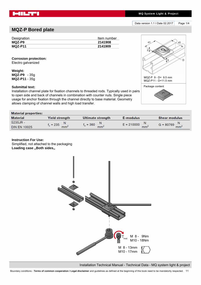
Designation Item numberMQZ-P9 2141908MQZ-P11 2141909
Corrosion protection:Electro galvanized
Weight:MQZ-P9 - 35gMQZ-P11 - 35g
Submittal text:Installation channel plate for fixation channels to threaded rods. Typically used in pairs to open side and back of channels in combination with counter nuts. Single piece usage for anchor fixation through the channel directly to base material. Geometry allows clamping of channel walls and high load transfer.
Instruction For Use:Simplified, not attached to the packagingLoading case ,,Both sides,,
M 8 - 9NmM10 - 18Nm
M 8 - 13mmM10 - 17mm
MQZ-P 9 - D= 9.5 mmMQZ-P11 - D=11.5 mm

12
MQ System Light & Project
Installation Technical Manual - Technical Data - MQ system light & project
Boundary conditions - Terms of common cooperation / Legal disclaimer and guidelines as defined at the beginning of this book need to be mandatorily respected.
Data version 1.1 I Date 02.2017
MQZ-P Bored plate
Page 2/4
Possible loading cases
Both sides
Design criteria used for loading capacity
Methodology:• Finite element analysis
Standards and codes:• EN 1990 Basics of structural design 03.2003• EN 1991-1-1 Eurocode 1: Actions on structures – Part 1-1: General
actions – densities, self-weight, imposed loads for buildings 09.2011• EN 1993-1-1 Eurocode 3: Design of steel structures – Part 1-1: General
rules and rules for buildings 03.2012• EN 1993-1-3 Eurocode 3: Design of steel structures – Part 1-3: General
rules- Supplementary rules for cold-formed members andsheeting 03.2012
• EN 1993-1-5 Eurocode 3: Design of steel structures – Part 1-5: Platedstructural elements 03.2012
• EN 1993-1-8 Eurocode 3: Design of steel structures – Part 1-8: Design ofjoints 03.2012
EN 10025-2 Hot rolled products of structural steels- Part 2: technicaldelivery conditions for non-alloy structural steels 02.2005
• RAL-GZ 655 Pipe Supports 04.2008
Software: • Ansys 16.0• Microsoft Excel
Environmental conditions: • static loads• no fatigue loads
Simplified drawing:
MQZ-P 9 - D= 9.5 mmMQZ-P11 - D=11.5 mm
13
MQ System Light & Project
Installation Technical Manual - Technical Data - MQ system light & project
Boundary conditions - Terms of common cooperation / Legal disclaimer and guidelines as defined at the beginning of this book need to be mandatorily respected.
Data version 1.1 I Date 02.2017
MQZ-P Bored plate
Page 3/4
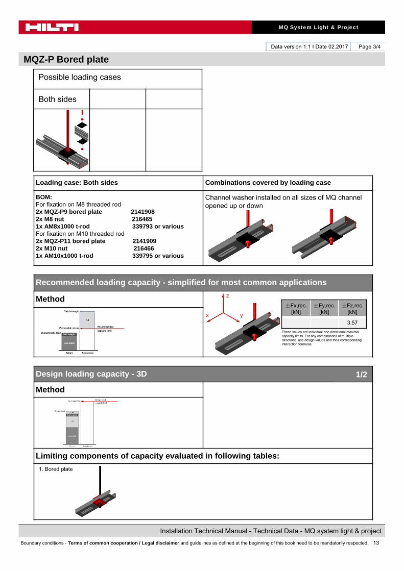
Loading case: Both sides Combinations covered by loading case
BOM:For fixation on M8 threaded rod2x MQZ-P9 bored plate 21419082x M8 nut 2164651x AM8x1000 t-rod 339793 or variousFor fixation on M10 threaded rod2x MQZ-P11 bored plate 21419092x M10 nut 2164661x AM10x1000 t-rod 339795 or various
Channel washer installed on all sizes of MQ channel opened up or down
Recommended loading capacity - simplified for most common applications
Method
Design loading capacity - 3D
Method
Limiting components of capacity evaluated in following tables:
1. Bored plate
±Fx,rec. [kN]
±Fy,rec. [kN]
±Fz,rec. [kN]
3.57
1/2
Possible loading cases
Both sides
z
yx
These values are individual one directional maximal capacity limits. For any combinations of multiple directions, use design values and their corresponding interaction formulas.
14
MQ System Light & Project
Installation Technical Manual - Technical Data - MQ system light & project
Boundary conditions - Terms of common cooperation / Legal disclaimer and guidelines as defined at the beginning of this book need to be mandatorily respected.
Data version 1.1 I Date 02.2017
MQZ-P Bored plate
Page 4/4
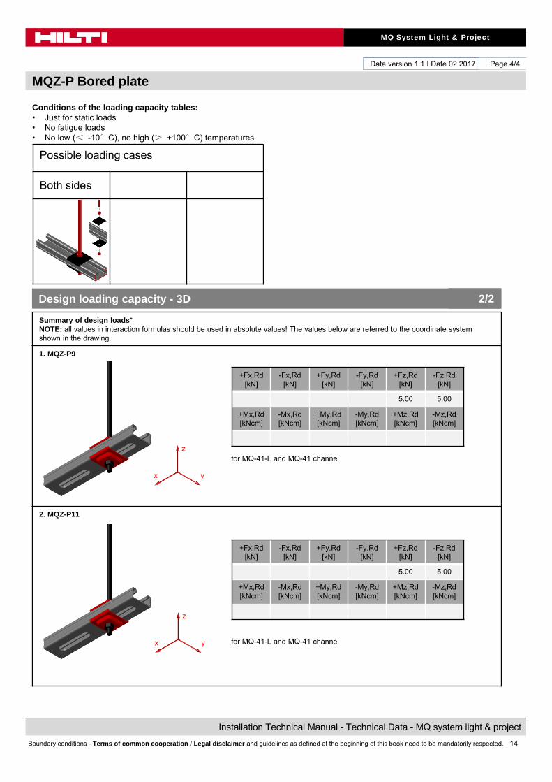
Conditions of the loading capacity tables:• Just for static loads• No fatigue loads• No low (< -10°C), no high (> +100°C) temperatures
Summary of design loads*NOTE: all values in interaction formulas should be used in absolute values! The values below are referred to the coordinate system shown in the drawing.
1. MQZ-P9
for MQ-41-L and MQ-41 channel
2. MQZ-P11
for MQ-41-L and MQ-41 channel
+Fx,Rd[kN]
-Fx,Rd[kN]
+Fy,Rd[kN]
-Fy,Rd[kN]
+Fz,Rd[kN]
-Fz,Rd[kN]
5.00 5.00
+Mx,Rd[kNcm]
-Mx,Rd[kNcm]
+My,Rd[kNcm]
-My,Rd[kNcm]
+Mz,Rd[kNcm]
-Mz,Rd[kNcm]
+Fx,Rd[kN]
-Fx,Rd[kN]
+Fy,Rd[kN]
-Fy,Rd[kN]
+Fz,Rd[kN]
-Fz,Rd[kN]
5.00 5.00
+Mx,Rd[kNcm]
-Mx,Rd[kNcm]
+My,Rd[kNcm]
-My,Rd[kNcm]
+Mz,Rd[kNcm]
-Mz,Rd[kNcm]
Design loading capacity - 3D 2/2
Possible loading cases
Both sides
z
yx
z
yx
15
MQ System Light & Project
Installation Technical Manual - Technical Data - MQ system light & project
Boundary conditions - Terms of common cooperation / Legal disclaimer and guidelines as defined at the beginning of this book need to be mandatorily respected.
Data version 1.1 I Date 02.2017
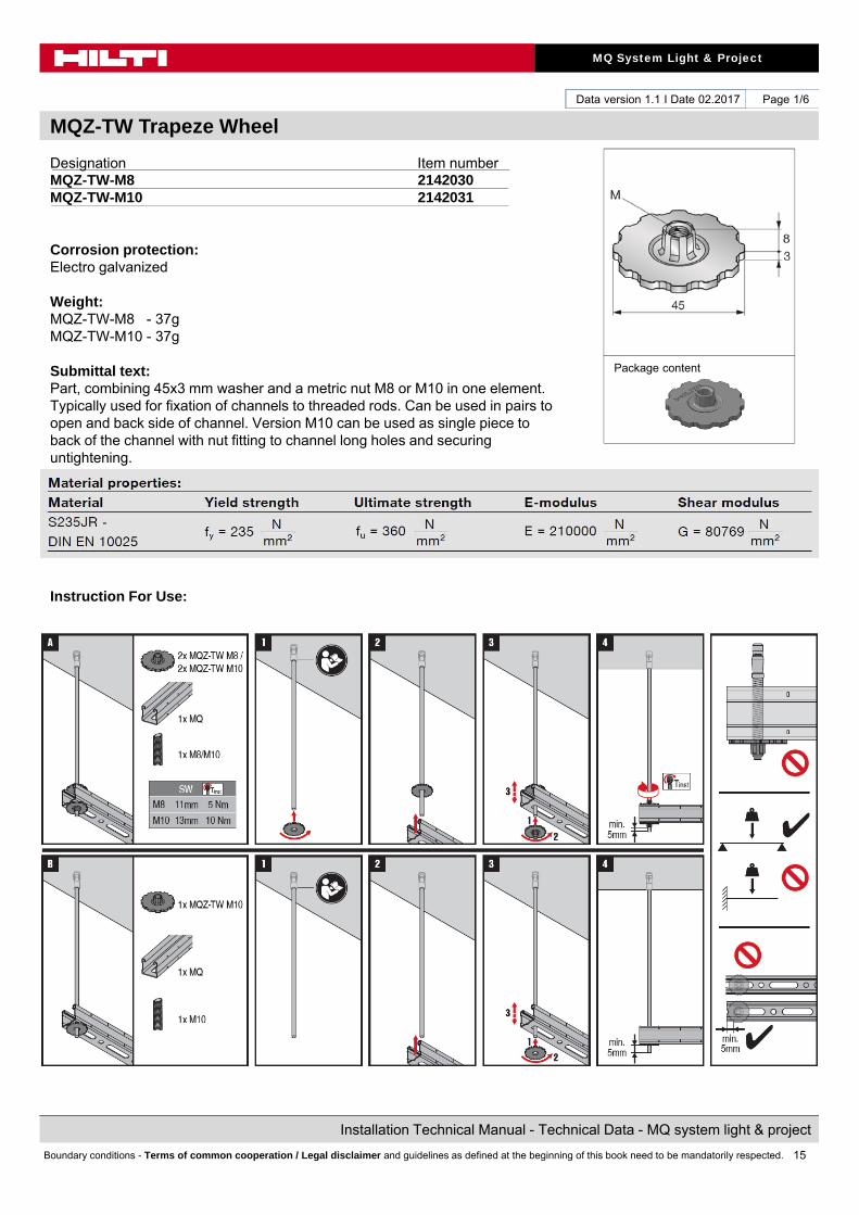
MQZ-TW Trapeze Wheel
Page 1/6
Designation Item numberMQZ-TW-M8 2142030MQZ-TW-M10 2142031
Corrosion protection:Electro galvanized
Weight:MQZ-TW-M8 - 37gMQZ-TW-M10 - 37g
Submittal text:Part, combining 45x3 mm washer and a metric nut M8 or M10 in one element. Typically used for fixation of channels to threaded rods. Can be used in pairs to open and back side of channel. Version M10 can be used as single piece to back of the channel with nut fitting to channel long holes and securing untightening.
Instruction For Use:
Package content

16
MQ System Light & Project
Installation Technical Manual - Technical Data - MQ system light & project
Boundary conditions - Terms of common cooperation / Legal disclaimer and guidelines as defined at the beginning of this book need to be mandatorily respected.
Data version 1.1 I Date 02.2017
MQZ-TW Trapeze Wheel
Page 2/6
Possible loading cases
Bottom side Both sides
Design criteria used for loading capacity
Methodology:• Finite element analysis
Standards and codes:• EN 1990 Basics of structural design 03.2003• EN 1991-1-1 Eurocode 1: Actions on structures – Part 1-1: General
actions – densities, self-weight, imposed loads for buildings 09.2011• EN 1993-1-1 Eurocode 3: Design of steel structures – Part 1-1: General
rules and rules for buildings 03.2012• EN 1993-1-3 Eurocode 3: Design of steel structures – Part 1-3: General
rules- Supplementary rules for cold-formed members andsheeting 03.2012
• EN 1993-1-5 Eurocode 3: Design of steel structures – Part 1-5: Platedstructural elements 03.2012
• EN 1993-1-8 Eurocode 3: Design of steel structures – Part 1-8: Design ofjoints 03.2012
EN 10025-2 Hot rolled products of structural steels- Part 2: technicaldelivery conditions for non-alloy structural steels 02.2005
• RAL-GZ 655 Pipe Supports 04.2008
Software: • Ansys 16.0• Microsoft Excel
Environmental conditions: • static loads• no fatigue loads
Simplified drawing:
17
MQ System Light & Project
Installation Technical Manual - Technical Data - MQ system light & project
Boundary conditions - Terms of common cooperation / Legal disclaimer and guidelines as defined at the beginning of this book need to be mandatorily respected.
Data version 1.1 I Date 02.2017
MQZ-TW Trapeze Wheel
Page 3/6
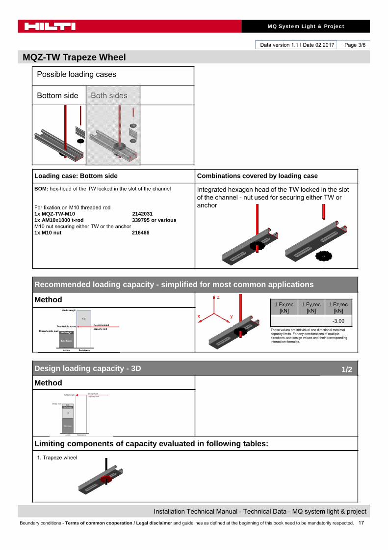
Loading case: Bottom side Combinations covered by loading case
BOM: hex-head of the TW locked in the slot of the channel
For fixation on M10 threaded rod1x MQZ-TW-M10 21420311x AM10x1000 t-rod 339795 or variousM10 nut securing either TW or the anchor1x M10 nut 216466
Integrated hexagon head of the TW locked in the slot of the channel - nut used for securing either TW or anchor
Recommended loading capacity - simplified for most common applications
Method
Design loading capacity - 3D
Method
Limiting components of capacity evaluated in following tables:
±Fx,rec. [kN]
±Fy,rec. [kN]
±Fz,rec. [kN]
-3.00
These values are individual one directional maximal capacity limits. For any combinations of multiple directions, use design values and their corresponding interaction formulas.
1/2
Possible loading cases
Bottom side Both sides
z
yx
1. Trapeze wheel
18
MQ System Light & Project
Installation Technical Manual - Technical Data - MQ system light & project
Boundary conditions - Terms of common cooperation / Legal disclaimer and guidelines as defined at the beginning of this book need to be mandatorily respected.
Data version 1.1 I Date 02.2017
MQZ-TW Trapeze Wheel
Page 4/6
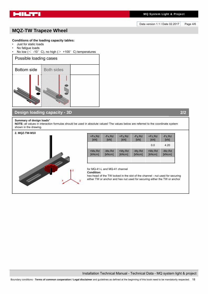
Conditions of the loading capacity tables:• Just for static loads• No fatigue loads• No low (< -10°C), no high (> +100°C) temperatures
Summary of design loads*NOTE: all values in interaction formulas should be used in absolute values! The values below are referred to the coordinate system shown in the drawing.
2. MQZ-TW-M10
for MQ-41-L and MQ-41 channelCondition:hex-head of the TW locked in the slot of the channel - nut used for securing either TW or anchor and hex nut used for securing either the TW or anchor
+Fx,Rd[kN]
-Fx,Rd[kN]
+Fy,Rd[kN]
-Fy,Rd[kN]
+Fz,Rd[kN]
-Fz,Rd[kN]
0.0 4.20
+Mx,Rd[kNcm]
-Mx,Rd[kNcm]
+My,Rd[kNcm]
-My,Rd[kNcm]
+Mz,Rd[kNcm]
-Mz,Rd[kNcm]
Design loading capacity - 3D 2/2
Possible loading cases
Bottom side Both sides
z
yx
19
MQ System Light & Project
Installation Technical Manual - Technical Data - MQ system light & project
Boundary conditions - Terms of common cooperation / Legal disclaimer and guidelines as defined at the beginning of this book need to be mandatorily respected.
Data version 1.1 I Date 02.2017
MQZ-TW Trapeze Wheel
Page 5/6
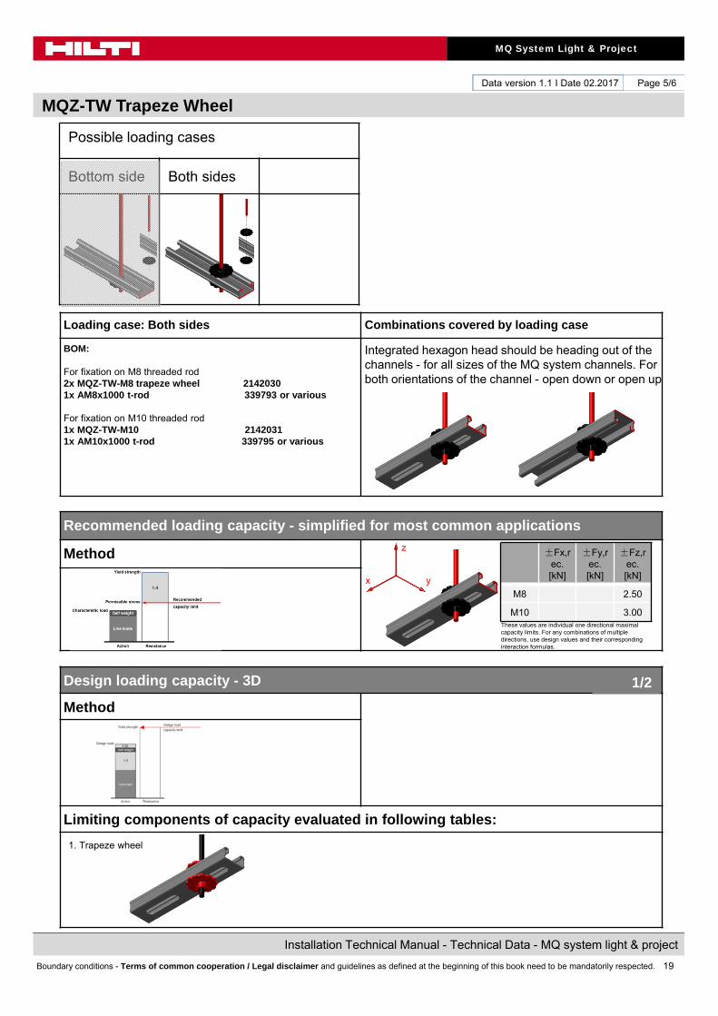
Loading case: Both sides Combinations covered by loading case
BOM:
For fixation on M8 threaded rod 2x MQZ-TW-M8 trapeze wheel 21420301x AM8x1000 t-rod 339793 or various
For fixation on M10 threaded rod1x MQZ-TW-M10 21420311x AM10x1000 t-rod 339795 or various
Integrated hexagon head should be heading out of the channels - for all sizes of the MQ system channels. For both orientations of the channel - open down or open up
Recommended loading capacity - simplified for most common applications
Method
Design loading capacity - 3D
Method
Limiting components of capacity evaluated in following tables:
These values are individual one directional maximal capacity limits. For any combinations of multiple directions, use design values and their corresponding interaction formulas.
1/2
Possible loading cases
Bottom side Both sides
z
yx
±Fx,rec. [kN]
±Fy,rec. [kN]
±Fz,rec. [kN]
M8 2.50
M10 3.00
1. Trapeze wheel
20
MQ System Light & Project
Installation Technical Manual - Technical Data - MQ system light & project
Boundary conditions - Terms of common cooperation / Legal disclaimer and guidelines as defined at the beginning of this book need to be mandatorily respected.
Data version 1.1 I Date 02.2017
MQZ-TW Trapeze Wheel
Page 6/6
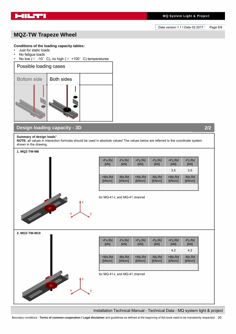
Conditions of the loading capacity tables:• Just for static loads• No fatigue loads• No low (< -10°C), no high (> +100°C) temperatures
Summary of design loads*NOTE: all values in interaction formulas should be used in absolute values! The values below are referred to the coordinate system shown in the drawing.
1. MQZ-TW-M8
for MQ-41-L and MQ-41 channel
2. MQZ-TW-M10
for MQ-41-L and MQ-41 channel
+Fx,Rd[kN]
-Fx,Rd[kN]
+Fy,Rd[kN]
-Fy,Rd[kN]
+Fz,Rd[kN]
-Fz,Rd[kN]
3.5 3.5
+Mx,Rd[kNcm]
-Mx,Rd[kNcm]
+My,Rd[kNcm]
-My,Rd[kNcm]
+Mz,Rd[kNcm]
-Mz,Rd[kNcm]
+Fx,Rd[kN]
-Fx,Rd[kN]
+Fy,Rd[kN]
-Fy,Rd[kN]
+Fz,Rd[kN]
-Fz,Rd[kN]
4.2 4.2
+Mx,Rd[kNcm]
-Mx,Rd[kNcm]
+My,Rd[kNcm]
-My,Rd[kNcm]
+Mz,Rd[kNcm]
-Mz,Rd[kNcm]
Design loading capacity - 3D 2/2
Possible loading cases
Bottom side Both sides
z
yx
z
yx
21
MQ System Light & Project
Installation Technical Manual - Technical Data - MQ system light & project
Boundary conditions - Terms of common cooperation / Legal disclaimer and guidelines as defined at the beginning of this book need to be mandatorily respected.
Data version 1.1 I Date 02.2017
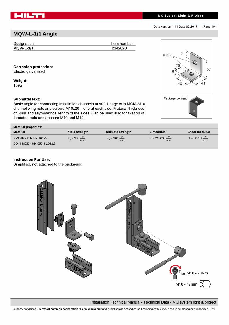
MQW-L-1/1 Angle
Page 1/4
Designation Item numberMQW-L-1/1 2142020
Corrosion protection:Electro galvanized
Weight:159g
Submittal text:Basic angle for connecting installation channels at 90°. Usage with MQM-M10 channel wing nuts and screws M10x20 – one at each side. Material thickness of 6mm and asymmetrical length of the sides. Can be used also for fixation of threaded rods and anchors M10 and M12.
Instruction For Use:Simplified, not attached to the packaging
Material properties:
Material Yield strength Ultimate strength E-modulus Shear modulus
S235JR - DIN EN 10025 Fy = 235 Fu = 360 E = 210000 G = 80769
DD11 MOD - HN 555-1 2012.3
Package content
M10 - 20Nm
M10 - 17mm
22
MQ System Light & Project
Installation Technical Manual - Technical Data - MQ system light & project
Boundary conditions - Terms of common cooperation / Legal disclaimer and guidelines as defined at the beginning of this book need to be mandatorily respected.
Data version 1.1 I Date 02.2017
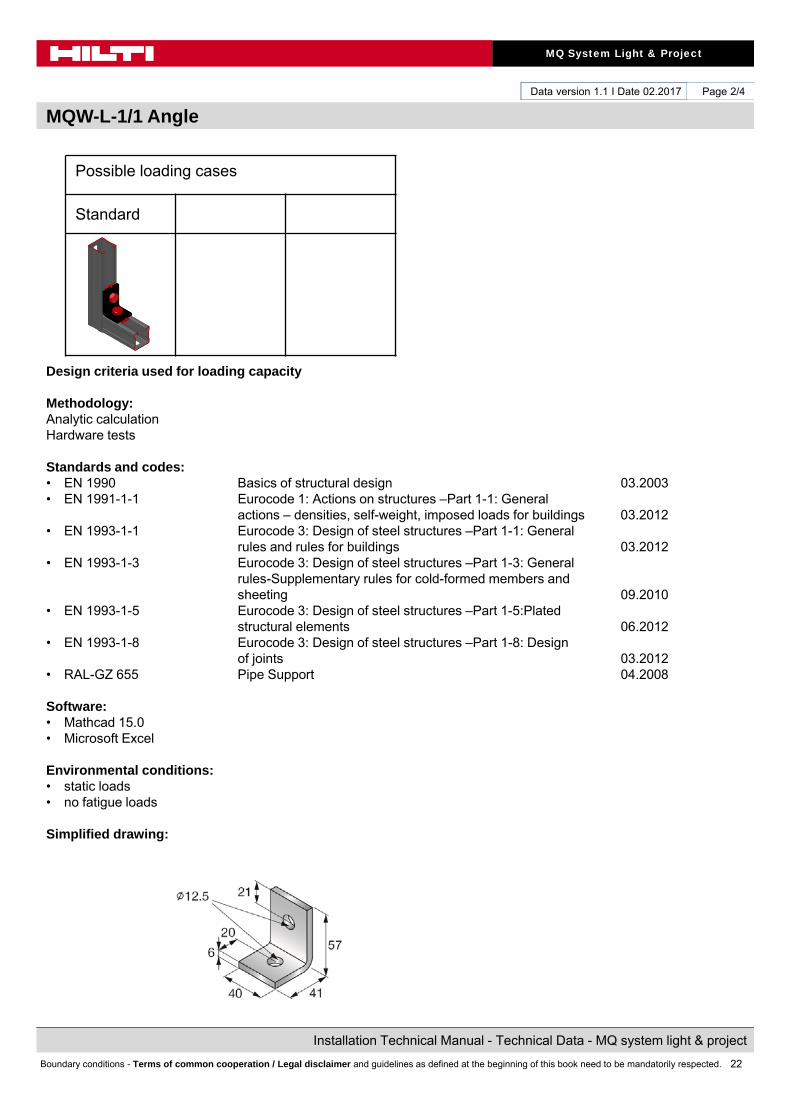
MQW-L-1/1 Angle
Page 2/4
Possible loading cases
Standard
Design criteria used for loading capacity
Methodology:Analytic calculationHardware tests
Standards and codes:• EN 1990 Basics of structural design 03.2003• EN 1991-1-1 Eurocode 1: Actions on structures –Part 1-1: General
actions – densities, self-weight, imposed loads for buildings 03.2012• EN 1993-1-1 Eurocode 3: Design of steel structures –Part 1-1: General
rules and rules for buildings 03.2012• EN 1993-1-3 Eurocode 3: Design of steel structures –Part 1-3: General
rules-Supplementary rules for cold-formed members and sheeting 09.2010
• EN 1993-1-5 Eurocode 3: Design of steel structures –Part 1-5:Plated structural elements 06.2012
• EN 1993-1-8 Eurocode 3: Design of steel structures –Part 1-8: Design of joints 03.2012
• RAL-GZ 655 Pipe Support 04.2008
Software: • Mathcad 15.0• Microsoft Excel
Environmental conditions: • static loads• no fatigue loads
Simplified drawing:
23
MQ System Light & Project
Installation Technical Manual - Technical Data - MQ system light & project
Boundary conditions - Terms of common cooperation / Legal disclaimer and guidelines as defined at the beginning of this book need to be mandatorily respected.
Data version 1.1 I Date 02.2017
MQW-L-1/1 Angle
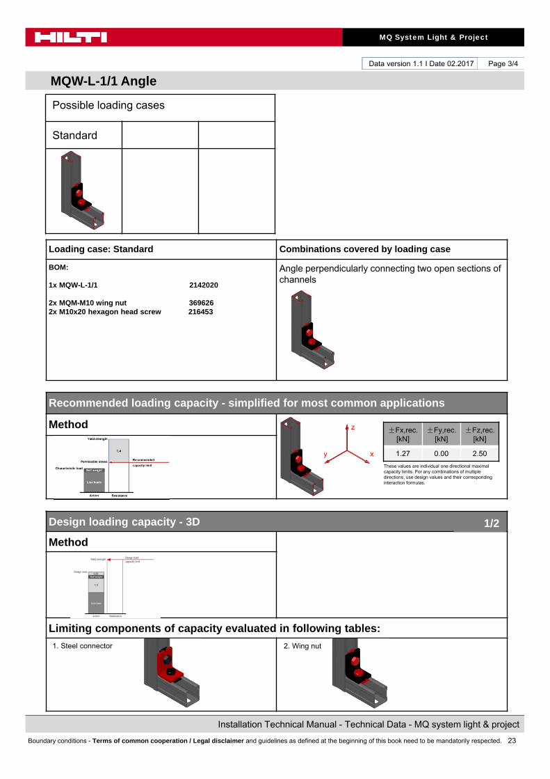
Page 3/4
Loading case: Standard Combinations covered by loading case
BOM:
1x MQW-L-1/1 2142020
2x MQM-M10 wing nut 3696262x M10x20 hexagon head screw 216453
Angle perpendicularly connecting two open sections of channels
Recommended loading capacity - simplified for most common applications
Method
Design loading capacity - 3D
Method
Limiting components of capacity evaluated in following tables:
1. Steel connector
±Fx,rec. [kN]
±Fy,rec. [kN]
±Fz,rec. [kN]
1.27 0.00 2.50
These values are individual one directional maximal capacity limits. For any combinations of multiple directions, use design values and their corresponding interaction formulas.
1/2
Possible loading cases
Standard
z
xy
2. Wing nut

24
MQ System Light & Project
Installation Technical Manual - Technical Data - MQ system light & project
Boundary conditions - Terms of common cooperation / Legal disclaimer and guidelines as defined at the beginning of this book need to be mandatorily respected.
Data version 1.1 I Date 02.2017
MQW-L-1/1 Angle
Page 4/4
Conditions of the loading capacity tables:• Just for static loads• No fatigue loads• No low (< -10°C), no high (> +100°C) temperatures
Summary of design loads*NOTE: all values in interaction formulas should be used in absolute values! The values below are referred to the coordinate system shown in the drawing.
1. Steel connector
Interaction:
2. Wing nut
Interaction:
+Fx,Rd[kN]
-Fx,Rd[kN]
+Fy,Rd[kN]
-Fy,Rd[kN]
+Fz,Rd[kN]
-Fz,Rd[kN]
3.15 5.84 0.00 0.00 4.85 4.45
+Mx,Rd[kNcm]
-Mx,Rd[kNcm]
+My,Rd[kNcm]
-My,Rd[kNcm]
+Mz,Rd[kNcm]
-Mz,Rd[kNcm]
0.00 0.00 0.00 0.00 0.00 0.00
+Fx,Rd[kN]
-Fx,Rd[kN]
+Fy,Rd[kN]
-Fy,Rd[kN]
+Fz,Rd[kN]
-Fz,Rd[kN]
3.55 4.88 0.00 0.00 7.00 7.00
+Mx,Rd[kNcm]
-Mx,Rd[kNcm]
+My,Rd[kNcm]
-My,Rd[kNcm]
+Mz,Rd[kNcm]
-Mz,Rd[kNcm]
0.00 0.00 0.00 0.00 0.00 0.00
Design loading capacity - 3D 2/2
Possible loading cases
Standard
z
xy
z
xy

25
MQ System Light & Project
Installation Technical Manual - Technical Data - MQ system light & project
Boundary conditions - Terms of common cooperation / Legal disclaimer and guidelines as defined at the beginning of this book need to be mandatorily respected.
Data version 1.1 I Date 02.2017
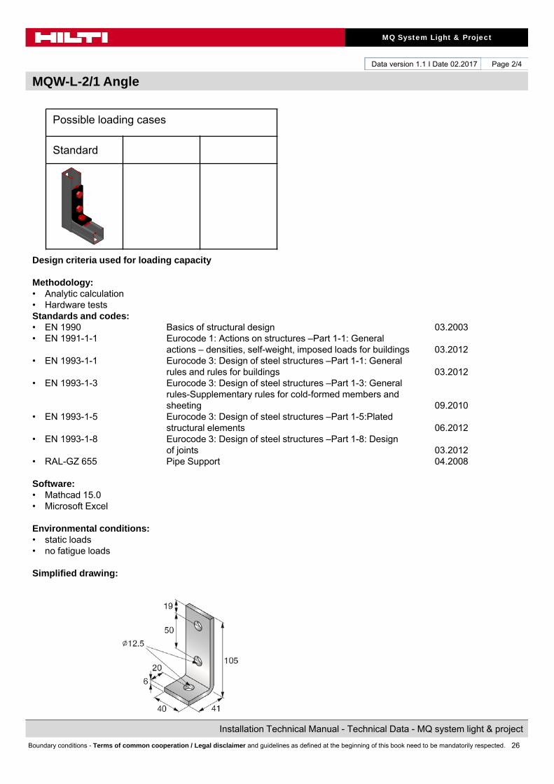
MQW-L-2/1 Angle
Page 1/4
Designation Item numberMQW-L-2/1 2142021
Corrosion protection:Electro galvanized
Weight:241g
Submittal text:Basic angle for connecting installation channels at 90°. Usage with MQM-M10 channel wing nuts and screws M10x20 – two on the long side and one on the short side. Material thickness of 6mm. Can be used also for fixation of threaded rods and anchors M10 and M12.
Instruction For Use:Simplified, not attached to the packaging
Package content
M10 - 20Nm
M10 - 17mm
26
MQ System Light & Project
Installation Technical Manual - Technical Data - MQ system light & project
Boundary conditions - Terms of common cooperation / Legal disclaimer and guidelines as defined at the beginning of this book need to be mandatorily respected.
Data version 1.1 I Date 02.2017
MQW-L-2/1 Angle
Page 2/4
Possible loading cases
Standard
Design criteria used for loading capacity
Methodology:• Analytic calculation• Hardware testsStandards and codes:• EN 1990 Basics of structural design 03.2003• EN 1991-1-1 Eurocode 1: Actions on structures –Part 1-1: General
actions – densities, self-weight, imposed loads for buildings 03.2012• EN 1993-1-1 Eurocode 3: Design of steel structures –Part 1-1: General
rules and rules for buildings 03.2012• EN 1993-1-3 Eurocode 3: Design of steel structures –Part 1-3: General
rules-Supplementary rules for cold-formed members and sheeting 09.2010
• EN 1993-1-5 Eurocode 3: Design of steel structures –Part 1-5:Platedstructural elements 06.2012
• EN 1993-1-8 Eurocode 3: Design of steel structures –Part 1-8: Designof joints 03.2012
• RAL-GZ 655 Pipe Support 04.2008
Software: • Mathcad 15.0• Microsoft Excel
Environmental conditions: • static loads• no fatigue loads
Simplified drawing:
27
MQ System Light & Project
Installation Technical Manual - Technical Data - MQ system light & project
Boundary conditions - Terms of common cooperation / Legal disclaimer and guidelines as defined at the beginning of this book need to be mandatorily respected.
Data version 1.1 I Date 02.2017
MQW-L-2/1 Angle
Page 3/4
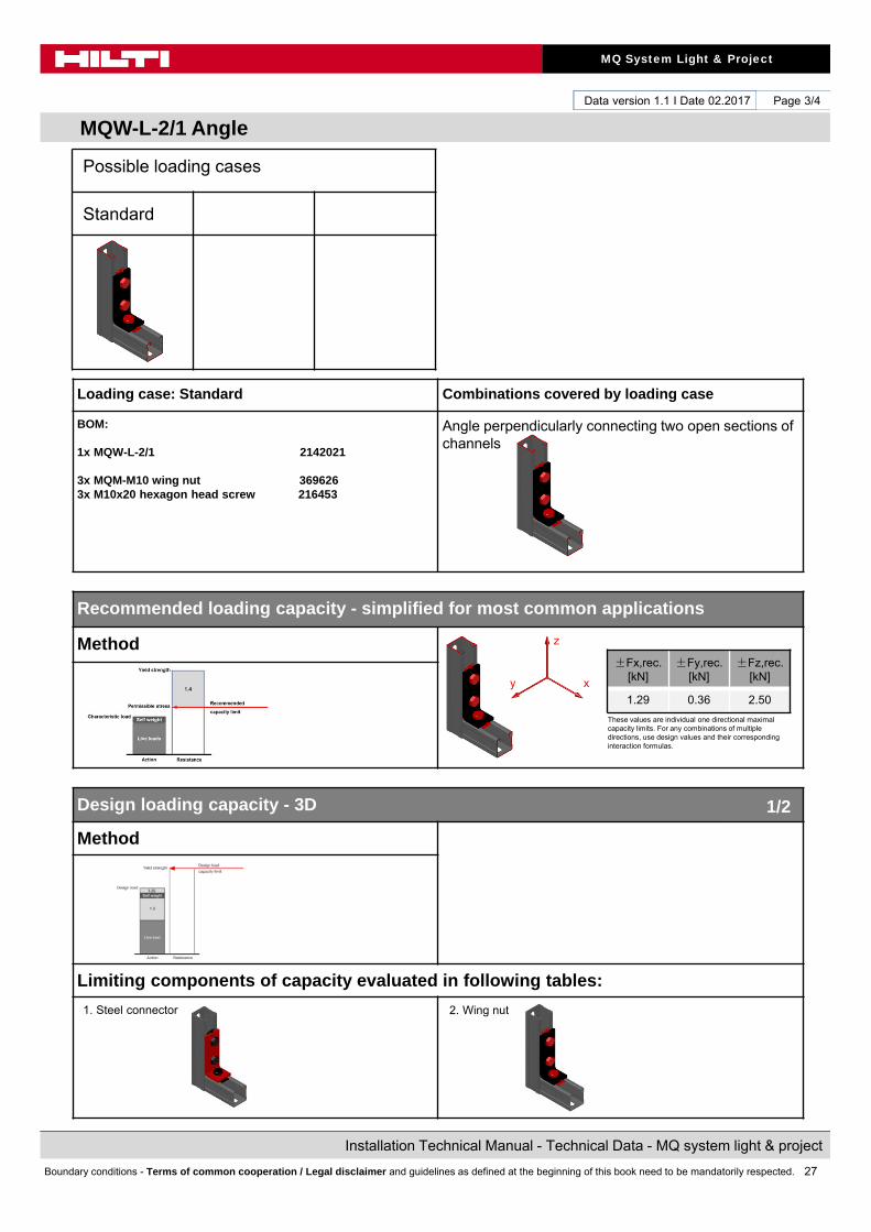
Loading case: Standard Combinations covered by loading case
BOM:
1x MQW-L-2/1 2142021
3x MQM-M10 wing nut 3696263x M10x20 hexagon head screw 216453
Angle perpendicularly connecting two open sections of channels
Recommended loading capacity - simplified for most common applications
Method
Design loading capacity - 3D
Method
Limiting components of capacity evaluated in following tables:
1. Steel connector
±Fx,rec. [kN]
±Fy,rec. [kN]
±Fz,rec. [kN]
1.29 0.36 2.50
These values are individual one directional maximal capacity limits. For any combinations of multiple directions, use design values and their corresponding interaction formulas.
1/2
Possible loading cases
Standard
2. Wing nut
z
xy

28
MQ System Light & Project
Installation Technical Manual - Technical Data - MQ system light & project
Boundary conditions - Terms of common cooperation / Legal disclaimer and guidelines as defined at the beginning of this book need to be mandatorily respected.
Data version 1.1 I Date 02.2017
MQW-L-2/1 Angle
Page 4/4
Conditions of the loading capacity tables:• Just for static loads• No fatigue loads• No low (< -10°C), no high (> +100°C) temperatures
Summary of design loads*NOTE: all values in interaction formulas should be used in absolute values! The values below are referred to the coordinate system shown in the drawing.
1. Steel connector
Interaction:
2. Wing nut
Interaction:Tension and shear parallel to channel
Shear transverse to channel
+Fx,Rd[kN]
-Fx,Rd[kN]
+Fy,Rd[kN]
-Fy,Rd[kN]
+Fz,Rd[kN]
-Fz,Rd[kN]
3.75 5.84 1.55 1.55 4.85 4.45
+Mx,Rd[kNcm]
-Mx,Rd[kNcm]
+My,Rd[kNcm]
-My,Rd[kNcm]
+Mz,Rd[kNcm]
-Mz,Rd[kNcm]
5.84 5.84 0.00 0.00 0.00 0.00
+Fx,Rd[kN]
-Fx,Rd[kN]
+Fy,Rd[kN]
-Fy,Rd[kN]
+Fz,Rd[kN]
-Fz,Rd[kN]
3.60 4.88 0.75 0.75 12.60 7.00
+Mx,Rd[kNcm]
-Mx,Rd[kNcm]
+My,Rd[kNcm]
-My,Rd[kNcm]
+Mz,Rd[kNcm]
-Mz,Rd[kNcm]
6.25 6.25 0.00 0.00 0.00 0.00
Design loading capacity - 3D 2/2
Possible loading cases
Standard
z
xy
z
xy

29
MQ System Light & Project
Installation Technical Manual - Technical Data - MQ system light & project
Boundary conditions - Terms of common cooperation / Legal disclaimer and guidelines as defined at the beginning of this book need to be mandatorily respected.
Data version 1.1 I Date 02.2017
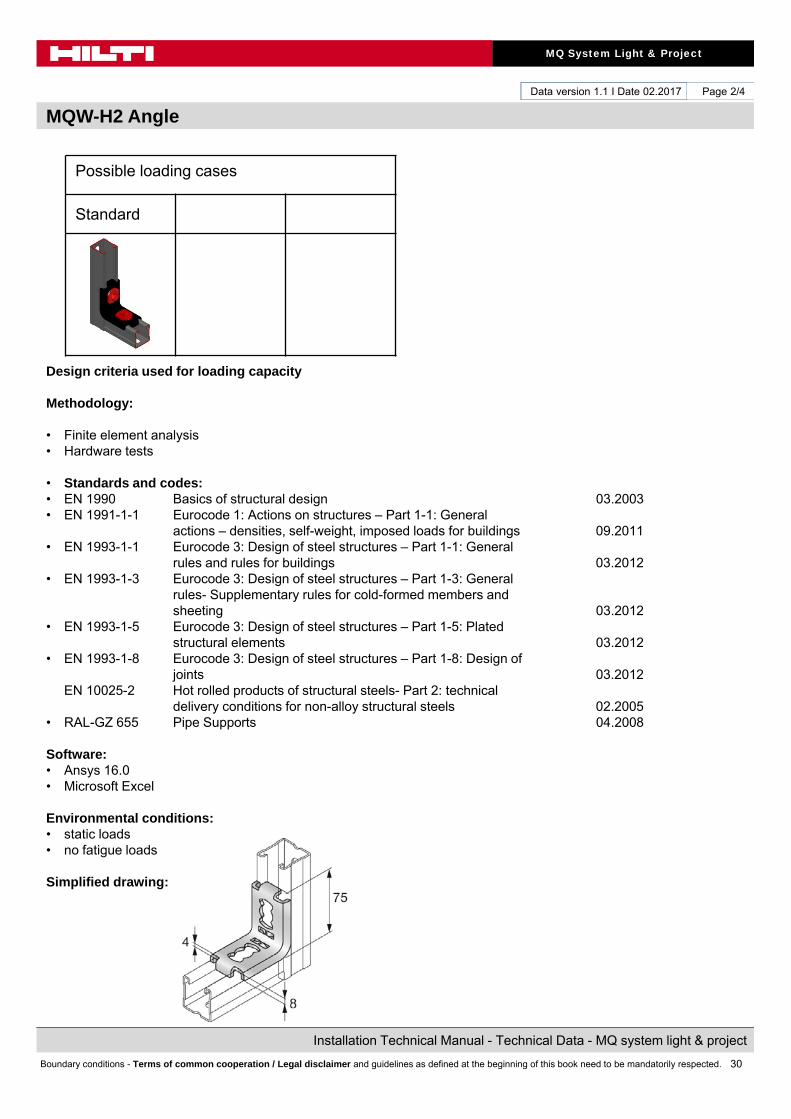
MQW-H2 Angle
Page 1/4
Designation Item numberMQW-H2 2141929
Corrosion protection:Electro galvanized
Weight:211g
Submittal text:Angle for connecting two channels at 90° in combination with two channel connectors MQN. Angle geometry and integrated bends allows high stiffness and direct load transfer to the installation channel.
Instruction For Use:
Material properties:
Material Yield strength Ultimate strength E-modulus Shear modulus
S275JR - DIN EN 10025-2 Fy = 275 Fu = 430 E = 210000 G = 80769
Package content
30
MQ System Light & Project
Installation Technical Manual - Technical Data - MQ system light & project
Boundary conditions - Terms of common cooperation / Legal disclaimer and guidelines as defined at the beginning of this book need to be mandatorily respected.
Data version 1.1 I Date 02.2017
MQW-H2 Angle
Page 2/4
Possible loading cases
Standard
Design criteria used for loading capacity
Methodology:
• Finite element analysis• Hardware tests
• Standards and codes:• EN 1990 Basics of structural design 03.2003• EN 1991-1-1 Eurocode 1: Actions on structures – Part 1-1: General
actions – densities, self-weight, imposed loads for buildings 09.2011• EN 1993-1-1 Eurocode 3: Design of steel structures – Part 1-1: General
rules and rules for buildings 03.2012• EN 1993-1-3 Eurocode 3: Design of steel structures – Part 1-3: General
rules- Supplementary rules for cold-formed members andsheeting 03.2012
• EN 1993-1-5 Eurocode 3: Design of steel structures – Part 1-5: Platedstructural elements 03.2012
• EN 1993-1-8 Eurocode 3: Design of steel structures – Part 1-8: Design ofjoints 03.2012
EN 10025-2 Hot rolled products of structural steels- Part 2: technicaldelivery conditions for non-alloy structural steels 02.2005
• RAL-GZ 655 Pipe Supports 04.2008
Software: • Ansys 16.0• Microsoft Excel
Environmental conditions: • static loads• no fatigue loads
Simplified drawing:
31
MQ System Light & Project
Installation Technical Manual - Technical Data - MQ system light & project
Boundary conditions - Terms of common cooperation / Legal disclaimer and guidelines as defined at the beginning of this book need to be mandatorily respected.
Data version 1.1 I Date 02.2017
MQW-H2 Angle
Page 3/4
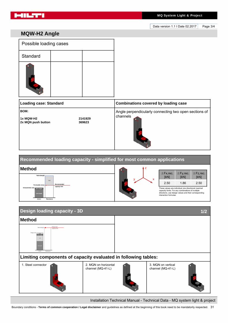
Loading case: Standard Combinations covered by loading case
BOM:
1x MQW-H2 21419292x MQN push button 369623
Angle perpendicularly connecting two open sections of channels
Recommended loading capacity - simplified for most common applications
Method
Design loading capacity - 3D
Method
Limiting components of capacity evaluated in following tables:
1. Steel connector
±Fx,rec. [kN]
±Fy,rec. [kN]
±Fz,rec. [kN]
2.50 1.86 2.50
These values are individual one directional maximal capacity limits. For any combinations of multiple directions, use design values and their corresponding interaction formulas.
1/2
Possible loading cases
Standard
2. MQN on horizontal channel (MQ-41-L)
z
xy
3. MQN on vertical channel (MQ-41-L)
32
MQ System Light & Project
Installation Technical Manual - Technical Data - MQ system light & project
Boundary conditions - Terms of common cooperation / Legal disclaimer and guidelines as defined at the beginning of this book need to be mandatorily respected.
Data version 1.1 I Date 02.2017
MQW-H2 Angle
Page 4/4
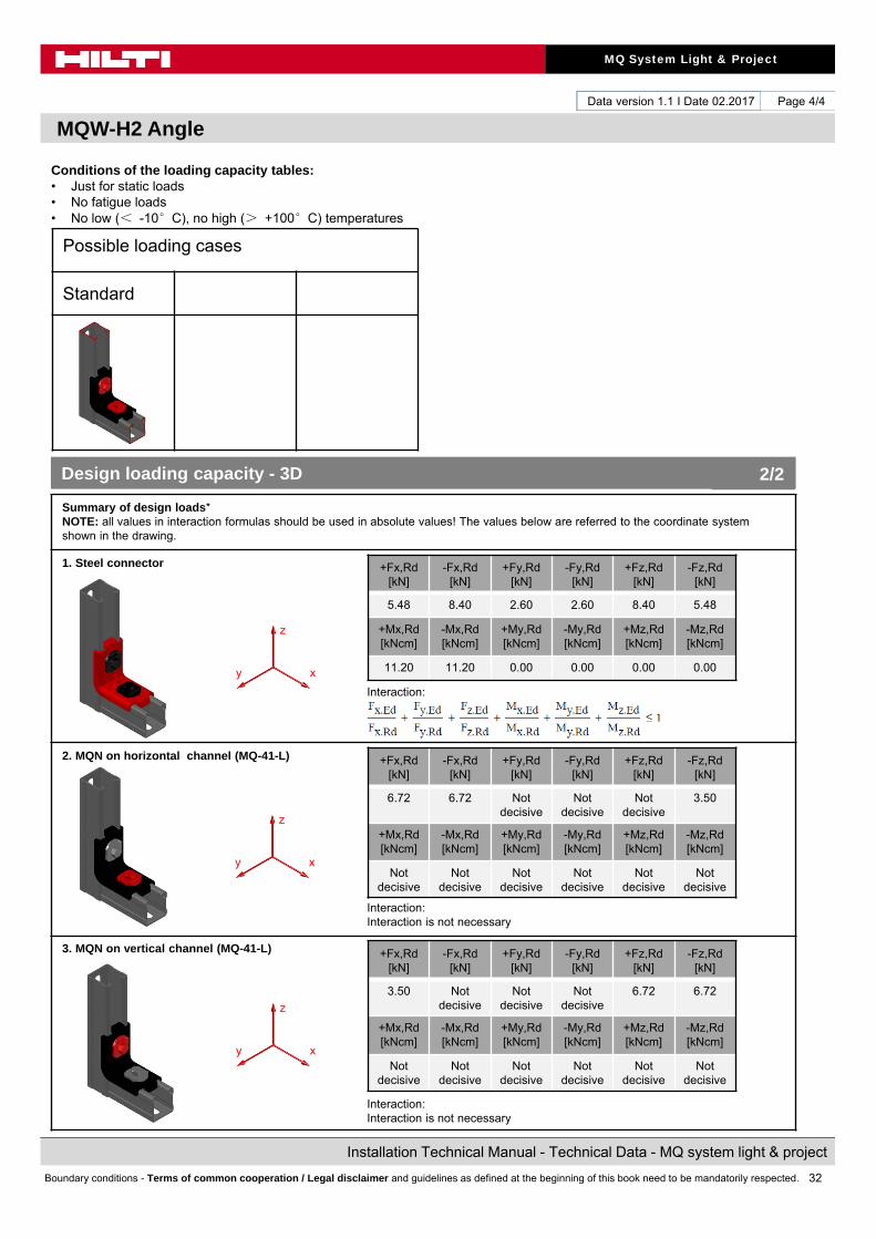
Conditions of the loading capacity tables:• Just for static loads• No fatigue loads• No low (< -10°C), no high (> +100°C) temperatures
Summary of design loads*NOTE: all values in interaction formulas should be used in absolute values! The values below are referred to the coordinate system shown in the drawing.
1. Steel connector
Interaction:
2. MQN on horizontal channel (MQ-41-L)
Interaction:Interaction is not necessary
3. MQN on vertical channel (MQ-41-L)
Interaction:Interaction is not necessary
+Fx,Rd[kN]
-Fx,Rd[kN]
+Fy,Rd[kN]
-Fy,Rd[kN]
+Fz,Rd[kN]
-Fz,Rd[kN]
5.48 8.40 2.60 2.60 8.40 5.48
+Mx,Rd[kNcm]
-Mx,Rd[kNcm]
+My,Rd[kNcm]
-My,Rd[kNcm]
+Mz,Rd[kNcm]
-Mz,Rd[kNcm]
11.20 11.20 0.00 0.00 0.00 0.00
+Fx,Rd[kN]
-Fx,Rd[kN]
+Fy,Rd[kN]
-Fy,Rd[kN]
+Fz,Rd[kN]
-Fz,Rd[kN]
6.72 6.72 Not decisive
Not decisive
Not decisive
3.50
+Mx,Rd[kNcm]
-Mx,Rd[kNcm]
+My,Rd[kNcm]
-My,Rd[kNcm]
+Mz,Rd[kNcm]
-Mz,Rd[kNcm]
Not decisive
Not decisive
Not decisive
Not decisive
Not decisive
Not decisive
Design loading capacity - 3D 2/2
Possible loading cases
Standard
z
xy
z
xy
z
xy
+Fx,Rd[kN]
-Fx,Rd[kN]
+Fy,Rd[kN]
-Fy,Rd[kN]
+Fz,Rd[kN]
-Fz,Rd[kN]
3.50 Not decisive
Not decisive
Not decisive
6.72 6.72
+Mx,Rd[kNcm]
-Mx,Rd[kNcm]
+My,Rd[kNcm]
-My,Rd[kNcm]
+Mz,Rd[kNcm]
-Mz,Rd[kNcm]
Not decisive
Not decisive
Not decisive
Not decisive
Not decisive
Not decisive

33
MQ System Light & Project
Installation Technical Manual - Technical Data - MQ system light & project
Boundary conditions - Terms of common cooperation / Legal disclaimer and guidelines as defined at the beginning of this book need to be mandatorily respected.
Data version 1.1 I Date 02.2017
MQW-L-6/2 Rail support
Page 1/6
Designation Item numberMQW-L-6/2 2141928
Corrosion protection:Electro galvanized
Weight:555g
Submittal text:Base connector for installation channels at 90°. Usage with two MQM-M10 channel wing nuts and screws M10x20. Fixation holes at the three sides of the connector allowing rotation of channel open side - when used with 41x41 or 41x21D channels. Two anchor holes with dimensions 18x11mm.
Instruction For Use:Simplified, not attached to the packaging
Loading case ,,Centric,, Loading case ,,Eccentric,,
Package content
M10 - 20Nm
M10 - 17mm
M10 - 20Nm
M10 - 17mm

34
MQ System Light & Project
Installation Technical Manual - Technical Data - MQ system light & project
Boundary conditions - Terms of common cooperation / Legal disclaimer and guidelines as defined at the beginning of this book need to be mandatorily respected.
Data version 1.1 I Date 02.2017
MQW-L-6/2 Rail support
Page 2/6
Possible loading cases
Centric Eccentric
Design criteria used for loading capacity
Methodology:
• Analytic calculation• Hardware tests
• Standards and codes:• EN 1990 Basics of structural design 03.2003• EN 1991-1-1 Eurocode 1: Actions on structures – Part 1-1: General
actions – densities, self-weight, imposed loads for buildings 03.2012• EN 1993-1-1 Eurocode 3: Design of steel structures – Part 1-1: General
rules and rules for buildings 03.2012• EN 1993-1-3 Eurocode 3: Design of steel structures – Part 1-3: General
rules- Supplementary rules for cold-formed members andsheeting 09.2010
• EN 1993-1-5 Eurocode 3: Design of steel structures – Part 1-5: Platedstructural elements 06.2012
• EN 1993-1-8 Eurocode 3: Design of steel structures – Part 1-8: Design ofjoints 03.2012
• RAL-GZ 655 Pipe Supports 04.2008
Software:
• Mathcad 15.0• Microsoft Excel
Environmental conditions: • static loads• no fatigue loads
Simplified drawing:

35
MQ System Light & Project
Installation Technical Manual - Technical Data - MQ system light & project
Boundary conditions - Terms of common cooperation / Legal disclaimer and guidelines as defined at the beginning of this book need to be mandatorily respected.
Data version 1.1 I Date 02.2017
MQW-L-6/2 Rail support
Page 3/6
Loading case: Centric Combinations covered by loading case
BOM:
1x MQW-L-6/2 2141928
2x MQM-M10 wing nut 3696262x M10x20 hexagon head screw 216453
Rail support connecting perpendicularly channel to base material
Recommended loading capacity - simplified for most common applications
Method
Design loading capacity - 3D
Method
Limiting components of capacity evaluated in following tables:
1. Steel connector
±Fx,rec. [kN]
±Fy,rec. [kN]
±Fz,rec. [kN]
0.43 0.89 5.00
These values are individual one directional maximal capacity limits. For any combinations of multiple directions, use design values and their corresponding interaction formulas.
1/2
Possible loading cases
Centric Eccentric
2. Wing nuts
z
x y
36
MQ System Light & Project
Installation Technical Manual - Technical Data - MQ system light & project
Boundary conditions - Terms of common cooperation / Legal disclaimer and guidelines as defined at the beginning of this book need to be mandatorily respected.
Data version 1.1 I Date 02.2017
MQW-L-6/2 Rail support
Page 4/6
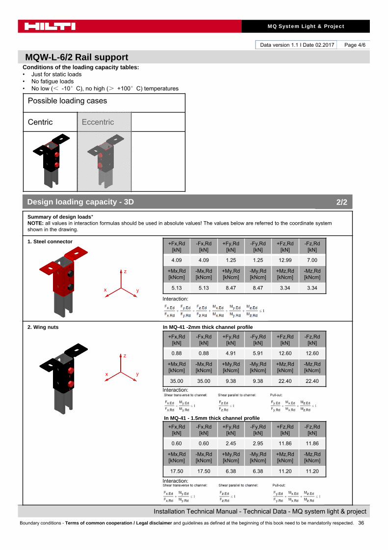
Conditions of the loading capacity tables:• Just for static loads• No fatigue loads• No low (< -10°C), no high (> +100°C) temperatures
Summary of design loads*NOTE: all values in interaction formulas should be used in absolute values! The values below are referred to the coordinate system shown in the drawing.
1. Steel connector
Interaction:
2. Wing nuts In MQ-41 -2mm thick channel profile
Interaction:
In MQ-41 - 1.5mm thick channel profile
Interaction:
+Fx,Rd[kN]
-Fx,Rd[kN]
+Fy,Rd[kN]
-Fy,Rd[kN]
+Fz,Rd[kN]
-Fz,Rd[kN]
4.09 4.09 1.25 1.25 12.99 7.00
+Mx,Rd[kNcm]
-Mx,Rd[kNcm]
+My,Rd[kNcm]
-My,Rd[kNcm]
+Mz,Rd[kNcm]
-Mz,Rd[kNcm]
5.13 5.13 8.47 8.47 3.34 3.34
+Fx,Rd[kN]
-Fx,Rd[kN]
+Fy,Rd[kN]
-Fy,Rd[kN]
+Fz,Rd[kN]
-Fz,Rd[kN]
0.88 0.88 4.91 5.91 12.60 12.60
+Mx,Rd[kNcm]
-Mx,Rd[kNcm]
+My,Rd[kNcm]
-My,Rd[kNcm]
+Mz,Rd[kNcm]
-Mz,Rd[kNcm]
35.00 35.00 9.38 9.38 22.40 22.40
Design loading capacity - 3D 2/2
Possible loading cases
Centric Eccentric
z
x y
z
x y
+Fx,Rd[kN]
-Fx,Rd[kN]
+Fy,Rd[kN]
-Fy,Rd[kN]
+Fz,Rd[kN]
-Fz,Rd[kN]
0.60 0.60 2.45 2.95 11.86 11.86
+Mx,Rd[kNcm]
-Mx,Rd[kNcm]
+My,Rd[kNcm]
-My,Rd[kNcm]
+Mz,Rd[kNcm]
-Mz,Rd[kNcm]
17.50 17.50 6.38 6.38 11.20 11.20
37
MQ System Light & Project
Installation Technical Manual - Technical Data - MQ system light & project
Boundary conditions - Terms of common cooperation / Legal disclaimer and guidelines as defined at the beginning of this book need to be mandatorily respected.
Data version 1.1 I Date 02.2017
MQW-L-6/2 Rail support
Page 5/6
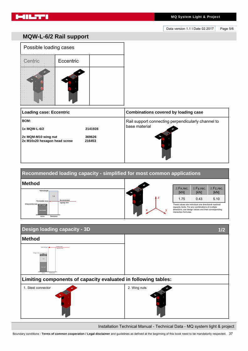
Loading case: Eccentric Combinations covered by loading case
BOM:
1x MQW-L-6/2 2141928
2x MQM-M10 wing nut 3696262x M10x20 hexagon head screw 216453
Rail support connecting perpendicularly channel to base material
Recommended loading capacity - simplified for most common applications
Method
Design loading capacity - 3D
Method
Limiting components of capacity evaluated in following tables:
1. Steel connector
±Fx,rec. [kN]
±Fy,rec. [kN]
±Fz,rec. [kN]
1.75 0.43 5.10
These values are individual one directional maximal capacity limits. For any combinations of multiple directions, use design values and their corresponding interaction formulas.
1/2
Possible loading cases
Centric Eccentric
2. Wing nuts
z
x y

38
MQ System Light & Project
Installation Technical Manual - Technical Data - MQ system light & project
Boundary conditions - Terms of common cooperation / Legal disclaimer and guidelines as defined at the beginning of this book need to be mandatorily respected.
Data version 1.1 I Date 02.2017
MQW-L-6/2 Rail support
Page 6/6
Conditions of the loading capacity tables:• Just for static loads• No fatigue loads• No low (< -10°C), no high (> +100°C) temperatures
Summary of design loads*NOTE: all values in interaction formulas should be used in absolute values! The values below are referred to the coordinate system shown in the drawing.
1. Steel connector
Interaction:
2. Wing nuts In MQ-41 -2mm thick channel profile
Interaction:
In MQ-41 - 1.5mm thick channel profile
Interaction:
+Fx,Rd[kN]
-Fx,Rd[kN]
+Fy,Rd[kN]
-Fy,Rd[kN]
+Fz,Rd[kN]
-Fz,Rd[kN]
4.09 4.09 1.25 1.25 9.43 7.14
+Mx,Rd[kNcm]
-Mx,Rd[kNcm]
+My,Rd[kNcm]
-My,Rd[kNcm]
+Mz,Rd[kNcm]
-Mz,Rd[kNcm]
5.13 5.13 8.47 8.47 3.34 3.34
+Fx,Rd[kN]
-Fx,Rd[kN]
+Fy,Rd[kN]
-Fy,Rd[kN]
+Fz,Rd[kN]
-Fz,Rd[kN]
4.91 4.91 0.88 1.05 12.60 12.60
+Mx,Rd[kNcm]
-Mx,Rd[kNcm]
+My,Rd[kNcm]
-My,Rd[kNcm]
+Mz,Rd[kNcm]
-Mz,Rd[kNcm]
6.25 6.25 35.00 35.00 22.40 22.40
Design loading capacity - 3D 2/2
Possible loading cases
Centric Eccentric
z
x y
z
x y
+Fx,Rd[kN]
-Fx,Rd[kN]
+Fy,Rd[kN]
-Fy,Rd[kN]
+Fz,Rd[kN]
-Fz,Rd[kN]
2.45 2.45 0.60 0.72 11.86 11.86
+Mx,Rd[kNcm]
-Mx,Rd[kNcm]
+My,Rd[kNcm]
-My,Rd[kNcm]
+Mz,Rd[kNcm]
-Mz,Rd[kNcm]
4.25 4.25 17.50 17.50 11.20 11.20
39
MQ System Light & Project
Installation Technical Manual - Technical Data - MQ system light & project
Boundary conditions - Terms of common cooperation / Legal disclaimer and guidelines as defined at the beginning of this book need to be mandatorily respected.
Data version 1.1 I Date 02.2017
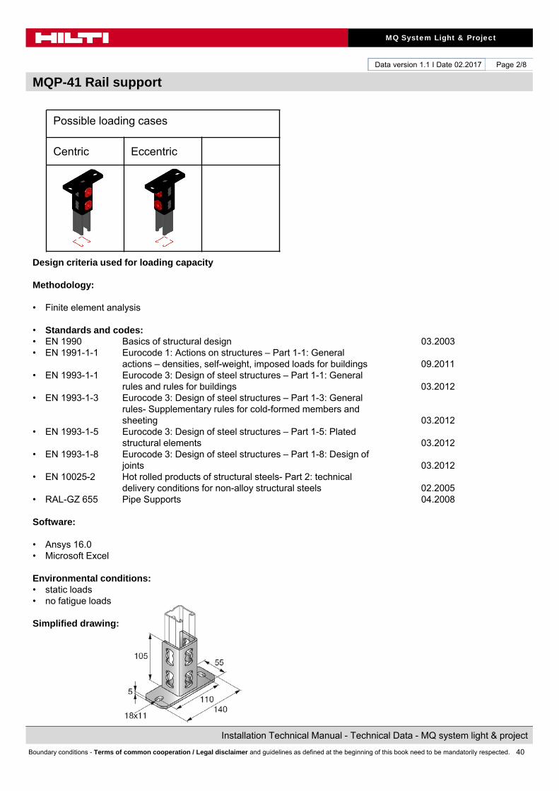
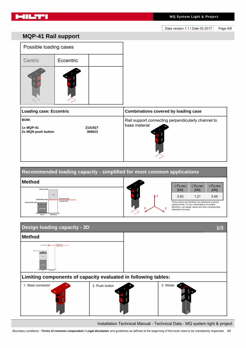
MQP-41 Rail support
Page 1/8
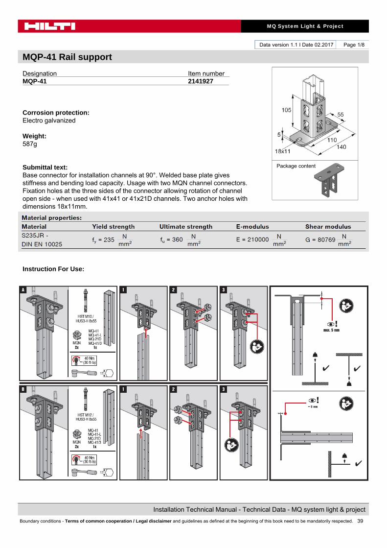
Designation Item numberMQP-41 2141927
Corrosion protection:Electro galvanized
Weight:587g
Submittal text:Base connector for installation channels at 90°. Welded base plate gives stiffness and bending load capacity. Usage with two MQN channel connectors. Fixation holes at the three sides of the connector allowing rotation of channel open side - when used with 41x41 or 41x21D channels. Two anchor holes with dimensions 18x11mm.
Instruction For Use:
Package content
40
MQ System Light & Project
Installation Technical Manual - Technical Data - MQ system light & project
Boundary conditions - Terms of common cooperation / Legal disclaimer and guidelines as defined at the beginning of this book need to be mandatorily respected.
Data version 1.1 I Date 02.2017
MQP-41 Rail support
Page 2/8
Possible loading cases
Centric Eccentric
Design criteria used for loading capacity
Methodology:
• Finite element analysis
• Standards and codes:• EN 1990 Basics of structural design 03.2003• EN 1991-1-1 Eurocode 1: Actions on structures – Part 1-1: General
actions – densities, self-weight, imposed loads for buildings 09.2011• EN 1993-1-1 Eurocode 3: Design of steel structures – Part 1-1: General
rules and rules for buildings 03.2012• EN 1993-1-3 Eurocode 3: Design of steel structures – Part 1-3: General
rules- Supplementary rules for cold-formed members andsheeting 03.2012
• EN 1993-1-5 Eurocode 3: Design of steel structures – Part 1-5: Platedstructural elements 03.2012
• EN 1993-1-8 Eurocode 3: Design of steel structures – Part 1-8: Design ofjoints 03.2012
• EN 10025-2 Hot rolled products of structural steels- Part 2: technical delivery conditions for non-alloy structural steels 02.2005
• RAL-GZ 655 Pipe Supports 04.2008
Software:
• Ansys 16.0• Microsoft Excel
Environmental conditions: • static loads• no fatigue loads
Simplified drawing:
41
MQ System Light & Project
Installation Technical Manual - Technical Data - MQ system light & project
Boundary conditions - Terms of common cooperation / Legal disclaimer and guidelines as defined at the beginning of this book need to be mandatorily respected.
Data version 1.1 I Date 02.2017
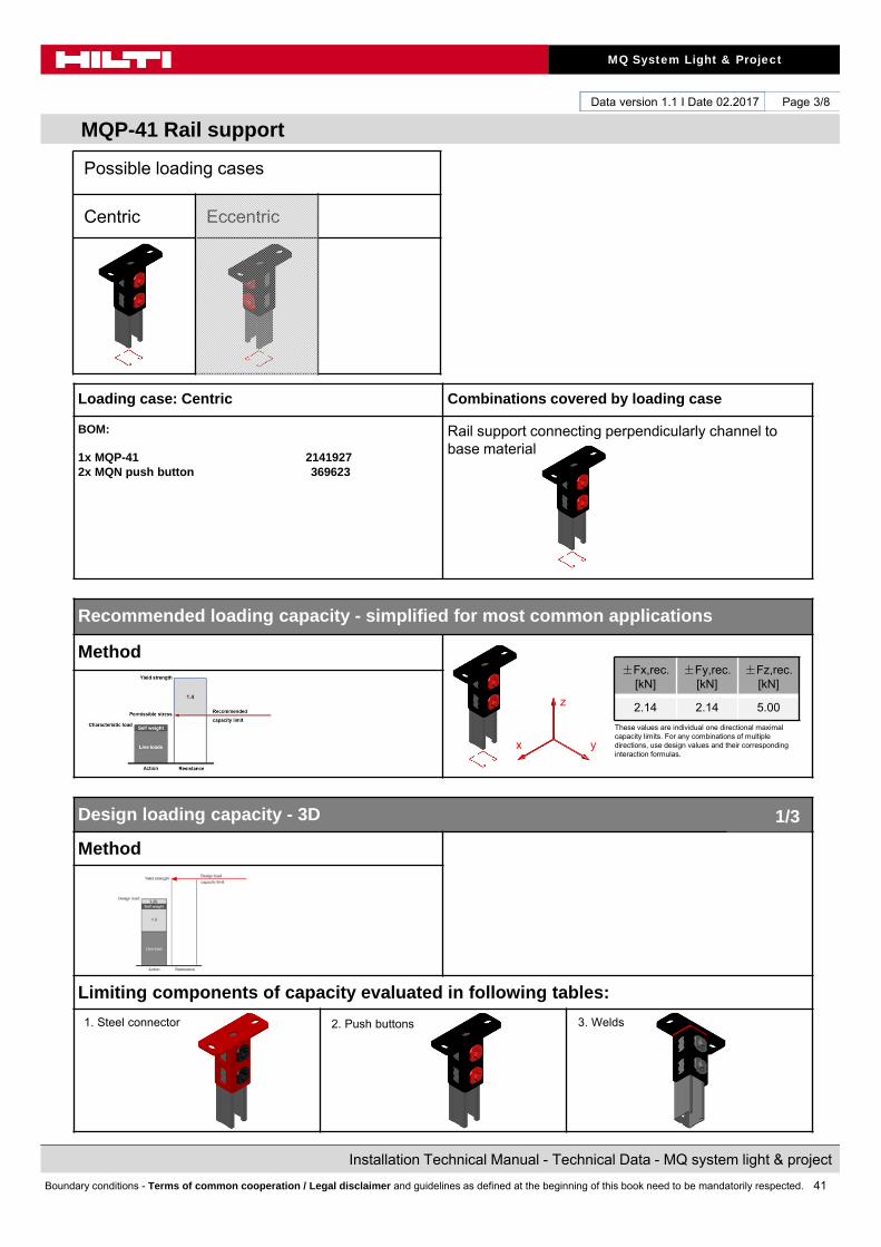
MQP-41 Rail support
Page 3/8
Loading case: Centric Combinations covered by loading case
BOM:
1x MQP-41 21419272x MQN push button 369623
Rail support connecting perpendicularly channel to base material
Recommended loading capacity - simplified for most common applications
Method
Design loading capacity - 3D
Method
Limiting components of capacity evaluated in following tables:
1. Steel connector
±Fx,rec. [kN]
±Fy,rec. [kN]
±Fz,rec. [kN]
2.14 2.14 5.00
These values are individual one directional maximal capacity limits. For any combinations of multiple directions, use design values and their corresponding interaction formulas.
1/3
Possible loading cases
Centric Eccentric
2. Push buttons
z
yx
3. Welds
42
MQ System Light & Project
Installation Technical Manual - Technical Data - MQ system light & project
Boundary conditions - Terms of common cooperation / Legal disclaimer and guidelines as defined at the beginning of this book need to be mandatorily respected.
Data version 1.1 I Date 02.2017
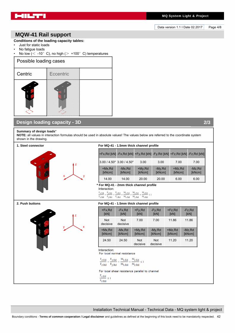
MQW-41 Rail support
Page 4/8
Conditions of the loading capacity tables:• Just for static loads• No fatigue loads• No low (< -10°C), no high (> +100°C) temperatures
Summary of design loads*NOTE: all values in interaction formulas should be used in absolute values! The values below are referred to the coordinate system shown in the drawing.
1. Steel connector For MQ-41 - 1.5mm thick channel profile
* For MQ-41 - 2mm thick channel profileInteraction:
2. Push buttons For MQ-41 - 1.5mm thick channel profile
Interaction:
+Fx,Rd [kN] -Fx,Rd [kN] +Fy,Rd [kN] -Fy,Rd [kN] +Fz,Rd [kN] -Fz,Rd [kN]
3.00 / 4.50* 3.00 / 4.50* 3.00 3.00 7.00 7.00
+Mx,Rd[kNcm]
-Mx,Rd[kNcm]
+My,Rd[kNcm]
-My,Rd[kNcm]
+Mz,Rd[kNcm]
-Mz,Rd[kNcm]
14.00 14.00 20.00 20.00 6.00 6.00
+Fx,Rd[kN]
-Fx,Rd[kN]
+Fy,Rd[kN]
-Fy,Rd[kN]
+Fz,Rd[kN]
-Fz,Rd[kN]
Notdecisive
Not decisive
7.00 7.00 11.86 11.86
+Mx,Rd[kNcm]
-Mx,Rd[kNcm]
+My,Rd[kNcm]
-My,Rd[kNcm]
+Mz,Rd[kNcm]
-Mz,Rd[kNcm]
24.50 24.50 Not decisive
Not decisive
11.20 11.20
Design loading capacity - 3D 2/3
Possible loading cases
Centric Eccentric
z
yx
z
xy
43
MQ System Light & Project
Installation Technical Manual - Technical Data - MQ system light & project
Boundary conditions - Terms of common cooperation / Legal disclaimer and guidelines as defined at the beginning of this book need to be mandatorily respected.
Data version 1.1 I Date 02.2017
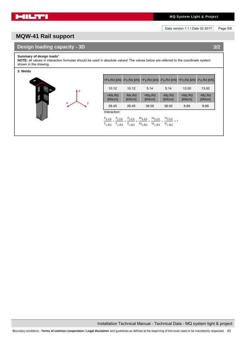
MQW-41 Rail support
Page 5/8
Summary of design loads*NOTE: all values in interaction formulas should be used in absolute values! The values below are referred to the coordinate system shown in the drawing.
3. Welds
Interaction:
+Fx,Rd [kN] -Fx,Rd [kN] +Fy,Rd [kN] -Fy,Rd [kN] +Fz,Rd [kN] -Fz,Rd [kN]
10.12 10.12 5.14 5.14 13.00 13.00
+Mx,Rd[kNcm]
-Mx,Rd[kNcm]
+My,Rd[kNcm]
-My,Rd[kNcm]
+Mz,Rd[kNcm]
-Mz,Rd[kNcm]
28.45 28.45 38.00 38.00 8.89 8.89
Design loading capacity - 3D 3/2
z
yx
44
MQ System Light & Project
Installation Technical Manual - Technical Data - MQ system light & project
Boundary conditions - Terms of common cooperation / Legal disclaimer and guidelines as defined at the beginning of this book need to be mandatorily respected.
Data version 1.1 I Date 02.2017
MQP-41 Rail support
Page 6/8
Loading case: Eccentric Combinations covered by loading case
BOM:
1x MQP-41 21419272x MQN push button 369623
Rail support connecting perpendicularly channel to base material
Recommended loading capacity - simplified for most common applications
Method
Design loading capacity - 3D
Method
Limiting components of capacity evaluated in following tables:
1. Steel connector
±Fx,rec. [kN]
±Fy,rec. [kN]
±Fz,rec. [kN]
3.93 1.21 5.00
These values are individual one directional maximal capacity limits. For any combinations of multiple directions, use design values and their corresponding interaction formulas.
1/3
Possible loading cases
Centric Eccentric
2. Push buttons 3. Welds
z
yx

45
MQ System Light & Project
Installation Technical Manual - Technical Data - MQ system light & project
Boundary conditions - Terms of common cooperation / Legal disclaimer and guidelines as defined at the beginning of this book need to be mandatorily respected.
Data version 1.1 I Date 02.2017
MQW-41 Rail support
Page 7/8
Conditions of the loading capacity tables:• Just for static loads• No fatigue loads• No low (< -10°C), no high (> +100°C) temperatures
Summary of design loads*NOTE: all values in interaction formulas should be used in absolute values! The values below are referred to the coordinate system shown in the drawing.
1. Steel connector For MQ-41 - 1.5mm thick channel profile
Interaction:
2. Push buttons For MQ-41 - 1.5mm thick channel profile
Interaction:
+Fx,Rd [kN] -Fx,Rd [kN] +Fy,Rd [kN] -Fy,Rd [kN] +Fz,Rd [kN] -Fz,Rd [kN]
5.50 5.50 1.70 1.70 7.00 7.00
+Mx,Rd[kNcm]
-Mx,Rd[kNcm]
+My,Rd[kNcm]
-My,Rd[kNcm]
+Mz,Rd[kNcm]
-Mz,Rd[kNcm]
9.00 9.00 35.00 35.00 6.00 6.00
+Fx,Rd[kN]
-Fx,Rd[kN]
+Fy,Rd[kN]
-Fy,Rd[kN]
+Fz,Rd[kN]
-Fz,Rd[kN]
7.00 7.00 1.70 1.70 11.86 11.86
+Mx,Rd[kNcm]
-Mx,Rd[kNcm]
+My,Rd[kNcm]
-My,Rd[kNcm]
+Mz,Rd[kNcm]
-Mz,Rd[kNcm]
5.95 5.95 35.52 35.52 11.20 11.20
Design loading capacity - 3D 2/3
Possible loading cases
Centric Eccentric
z
yx
z
xy

46
MQ System Light & Project
Installation Technical Manual - Technical Data - MQ system light & project
Boundary conditions - Terms of common cooperation / Legal disclaimer and guidelines as defined at the beginning of this book need to be mandatorily respected.
Data version 1.1 I Date 02.2017
MQW-41 Rail support
Page 8/8
Summary of design loads*NOTE: all values in interaction formulas should be used in absolute values! The values below are referred to the coordinate system shown in the drawing.
3. Welds
Interaction:
+Fx,Rd [kN] -Fx,Rd [kN] +Fy,Rd [kN] -Fy,Rd [kN] +Fz,Rd [kN] -Fz,Rd [kN]
12.92 12.92 5.03 5.03 16.60 16.60
+Mx,Rd[kNcm]
-Mx,Rd[kNcm]
+My,Rd[kNcm]
-My,Rd[kNcm]
+Mz,Rd[kNcm]
-Mz,Rd[kNcm]
14.23 14.23 38.00 38.00 8.89 8.89
Design loading capacity - 3D 3/2
z
yx
47
MQ System Light & Project
Installation Technical Manual - Technical Data - MQ system light & project
Boundary conditions - Terms of common cooperation / Legal disclaimer and guidelines as defined at the beginning of this book need to be mandatorily respected.
Data version 1.1 I Date 02.2017
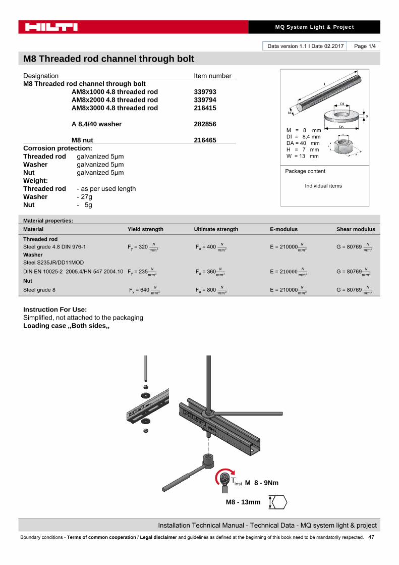
M8 Threaded rod channel through bolt
Page 1/4
Designation Item numberM8 Threaded rod channel through bolt
AM8x1000 4.8 threaded rod 339793AM8x2000 4.8 threaded rod 339794AM8x3000 4.8 threaded rod 216415
A 8,4/40 washer 282856
M8 nut 216465 Corrosion protection:Threaded rod galvanized 5μmWasher galvanized 5μmNut galvanized 5μmWeight:Threaded rod - as per used lengthWasher - 27gNut - 5g
Instruction For Use:Simplified, not attached to the packagingLoading case ,,Both sides,,
Material properties:
Material Yield strength Ultimate strength E-modulus Shear modulus
Threaded rod
Steel grade 4.8 DIN 976-1 Fy = 320 Fu = 400 E = 210000 G = 80769
Washer
Steel S235JR/DD11MOD
DIN EN 10025-2 2005.4/HN 547 2004.10 Fy = 235 Fu = 360 E = 210000
G = 80769
Nut
Steel grade 8 Fy = 640 Fu = 800 E = 210000
G = 80769
M = 8 mmDI = 8,4 mmDA = 40 mmH = 7 mmW = 13 mm
Package content
Individual items
M 8 - 9Nm
M8 - 13mm
48
MQ System Light & Project
Installation Technical Manual - Technical Data - MQ system light & project
Boundary conditions - Terms of common cooperation / Legal disclaimer and guidelines as defined at the beginning of this book need to be mandatorily respected.
Data version 1.1 I Date 02.2017
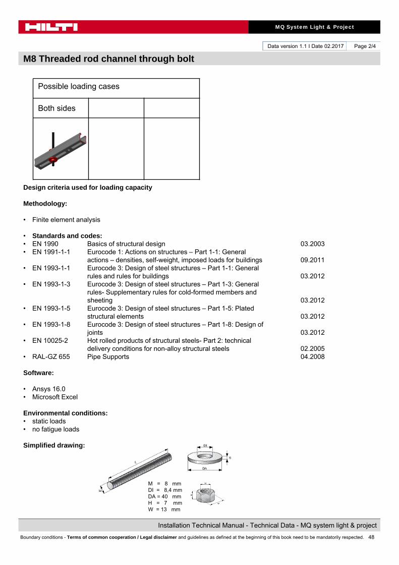
M8 Threaded rod channel through bolt
Page 2/4
Possible loading cases
Both sides
Design criteria used for loading capacity
Methodology:
• Finite element analysis
• Standards and codes:• EN 1990 Basics of structural design 03.2003• EN 1991-1-1 Eurocode 1: Actions on structures – Part 1-1: General
actions – densities, self-weight, imposed loads for buildings 09.2011• EN 1993-1-1 Eurocode 3: Design of steel structures – Part 1-1: General
rules and rules for buildings 03.2012• EN 1993-1-3 Eurocode 3: Design of steel structures – Part 1-3: General
rules- Supplementary rules for cold-formed members andsheeting 03.2012
• EN 1993-1-5 Eurocode 3: Design of steel structures – Part 1-5: Platedstructural elements 03.2012
• EN 1993-1-8 Eurocode 3: Design of steel structures – Part 1-8: Design ofjoints 03.2012
• EN 10025-2 Hot rolled products of structural steels- Part 2: technical delivery conditions for non-alloy structural steels 02.2005
• RAL-GZ 655 Pipe Supports 04.2008
Software:
• Ansys 16.0• Microsoft Excel
Environmental conditions: • static loads• no fatigue loads
Simplified drawing:
M = 8 mmDI = 8,4 mmDA = 40 mmH = 7 mmW = 13 mm
49
MQ System Light & Project
Installation Technical Manual - Technical Data - MQ system light & project
Boundary conditions - Terms of common cooperation / Legal disclaimer and guidelines as defined at the beginning of this book need to be mandatorily respected.
Data version 1.1 I Date 02.2017
M8 Threaded rod channel through bolt
Page 3/4
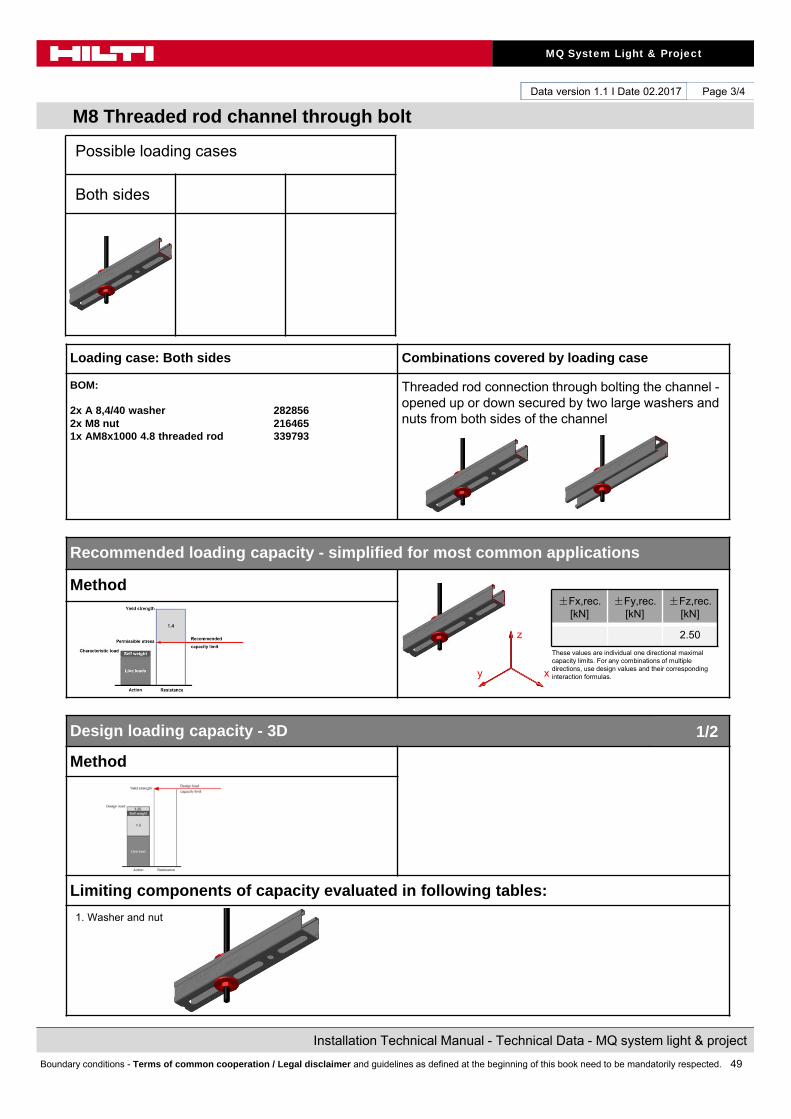
Loading case: Both sides Combinations covered by loading case
BOM:
2x A 8,4/40 washer 2828562x M8 nut 216465 1x AM8x1000 4.8 threaded rod 339793
Threaded rod connection through bolting the channel -opened up or down secured by two large washers and nuts from both sides of the channel
Recommended loading capacity - simplified for most common applications
Method
Design loading capacity - 3D
Method
Limiting components of capacity evaluated in following tables:
1. Washer and nut
±Fx,rec. [kN]
±Fy,rec. [kN]
±Fz,rec. [kN]
2.50
These values are individual one directional maximal capacity limits. For any combinations of multiple directions, use design values and their corresponding interaction formulas.
1/2
Possible loading cases
Both sides
z
xy

50
MQ System Light & Project
Installation Technical Manual - Technical Data - MQ system light & project
Boundary conditions - Terms of common cooperation / Legal disclaimer and guidelines as defined at the beginning of this book need to be mandatorily respected.
Data version 1.1 I Date 02.2017
M8 Threaded rod channel through bolt
Page 4/4
Conditions of the loading capacity tables:• Just for static loads• No fatigue loads• No low (< -10°C), no high (> +100°C) temperatures
Summary of design loads*NOTE: all values in interaction formulas should be used in absolute values! The values below are referred to the coordinate system shown in the drawing.
1. Washer and nut
Condition: valid for channel edge distance ≥ 100mm
+Fx,Rd [kN] -Fx,Rd [kN] +Fy,Rd [kN] -Fy,Rd [kN] +Fz,Rd [kN] -Fz,Rd [kN]
3.50 3.50
+Mx,Rd[kNcm]
-Mx,Rd[kNcm]
+My,Rd[kNcm]
-My,Rd[kNcm]
+Mz,Rd[kNcm]
-Mz,Rd[kNcm]
Design loading capacity - 3D 2/2
Possible loading cases
Both sides
z
xy
51
MQ System Light & Project
Installation Technical Manual - Technical Data - MQ system light & project
Boundary conditions - Terms of common cooperation / Legal disclaimer and guidelines as defined at the beginning of this book need to be mandatorily respected.
Data version 1.1 I Date 02.2017
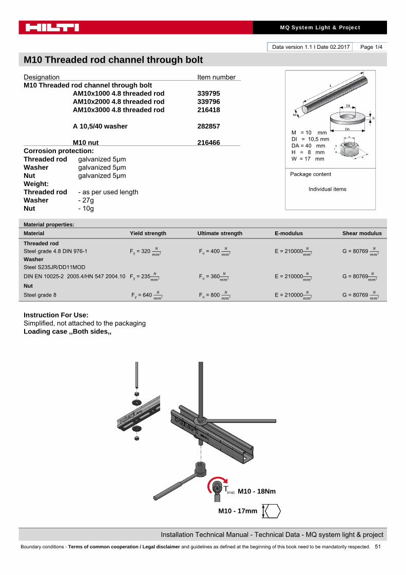
M10 Threaded rod channel through bolt
Page 1/4
Designation Item numberM10 Threaded rod channel through bolt
AM10x1000 4.8 threaded rod 339795AM10x2000 4.8 threaded rod 339796AM10x3000 4.8 threaded rod 216418
A 10,5/40 washer 282857
M10 nut 216466 Corrosion protection:Threaded rod galvanized 5μmWasher galvanized 5μmNut galvanized 5μmWeight:Threaded rod - as per used lengthWasher - 27gNut - 10g
Instruction For Use:Simplified, not attached to the packagingLoading case ,,Both sides,,
Material properties:
Material Yield strength Ultimate strength E-modulus Shear modulus
Threaded rod
Steel grade 4.8 DIN 976-1 Fy = 320 Fu = 400 E = 210000 G = 80769
Washer
Steel S235JR/DD11MOD
DIN EN 10025-2 2005.4/HN 547 2004.10 Fy = 235 Fu = 360 E = 210000
G = 80769
Nut
Steel grade 8 Fy = 640 Fu = 800 E = 210000
G = 80769
M = 10 mmDI = 10,5 mmDA = 40 mmH = 8 mmW = 17 mm
Package content
Individual items
M10 - 18Nm
M10 - 17mm

52
MQ System Light & Project
Installation Technical Manual - Technical Data - MQ system light & project
Boundary conditions - Terms of common cooperation / Legal disclaimer and guidelines as defined at the beginning of this book need to be mandatorily respected.
Data version 1.1 I Date 02.2017
M10 Threaded rod channel through bolt
Page 2/4
Possible loading cases
Both sides
Design criteria used for loading capacity
Methodology:
• Finite element analysis
• Standards and codes:• EN 1990 Basics of structural design 03.2003• EN 1991-1-1 Eurocode 1: Actions on structures – Part 1-1: General
actions – densities, self-weight, imposed loads for buildings 09.2011• EN 1993-1-1 Eurocode 3: Design of steel structures – Part 1-1: General
rules and rules for buildings 03.2012• EN 1993-1-3 Eurocode 3: Design of steel structures – Part 1-3: General
rules- Supplementary rules for cold-formed members andsheeting 03.2012
• EN 1993-1-5 Eurocode 3: Design of steel structures – Part 1-5: Platedstructural elements 03.2012
• EN 1993-1-8 Eurocode 3: Design of steel structures – Part 1-8: Design ofjoints 03.2012
• EN 10025-2 Hot rolled products of structural steels- Part 2: technical delivery conditions for non-alloy structural steels 02.2005
• RAL-GZ 655 Pipe Supports 04.2008
Software:
• Ansys 16.0• Microsoft Excel
Environmental conditions: • static loads• no fatigue loads
Simplified drawing:
M = 10 mmDI = 10,5 mmDA = 40 mmH = 8 mmW = 17 mm

53
MQ System Light & Project
Installation Technical Manual - Technical Data - MQ system light & project
Boundary conditions - Terms of common cooperation / Legal disclaimer and guidelines as defined at the beginning of this book need to be mandatorily respected.
Data version 1.1 I Date 02.2017
M10 Threaded rod channel through bolt
Page 3/4
Loading case: Both sides Combinations covered by loading case
BOM:
2x A 10,5/40 washer 2828572x M10 nut 216466 1x AM10x1000 4.8 threaded rod 339795
Threaded rod connection through bolting the channel -opened up or down secured by two large washers and nuts from both sides of the channel
Recommended loading capacity - simplified for most common applications
Method
Design loading capacity - 3D
Method
Limiting components of capacity evaluated in following tables:
1. Washer and nut
±Fx,rec. [kN]
±Fy,rec. [kN]
±Fz,rec. [kN]
3.00
These values are individual one directional maximal capacity limits. For any combinations of multiple directions, use design values and their corresponding interaction formulas.
1/2
Possible loading cases
Both sides
z
xy
54
MQ System Light & Project
Installation Technical Manual - Technical Data - MQ system light & project
Boundary conditions - Terms of common cooperation / Legal disclaimer and guidelines as defined at the beginning of this book need to be mandatorily respected.
Data version 1.1 I Date 02.2017
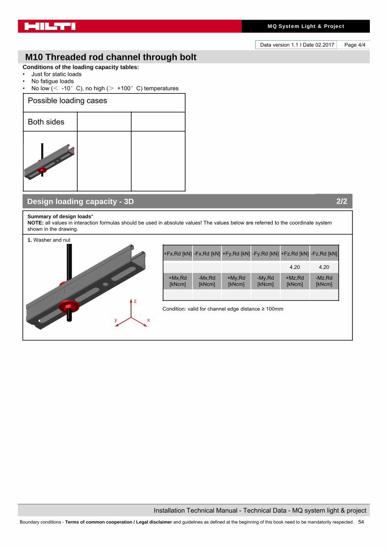
M10 Threaded rod channel through bolt
Page 4/4
Conditions of the loading capacity tables:• Just for static loads• No fatigue loads• No low (< -10°C), no high (> +100°C) temperatures
Summary of design loads*NOTE: all values in interaction formulas should be used in absolute values! The values below are referred to the coordinate system shown in the drawing.
1. Washer and nut
Condition: valid for channel edge distance ≥ 100mm
+Fx,Rd [kN] -Fx,Rd [kN] +Fy,Rd [kN] -Fy,Rd [kN] +Fz,Rd [kN] -Fz,Rd [kN]
4.20 4.20
+Mx,Rd[kNcm]
-Mx,Rd[kNcm]
+My,Rd[kNcm]
-My,Rd[kNcm]
+Mz,Rd[kNcm]
-Mz,Rd[kNcm]
Design loading capacity - 3D 2/2
Possible loading cases
Both sides
z
xy
55
MQ System Light & Project
Installation Technical Manual - Technical Data - MQ system light & project
Boundary conditions - Terms of common cooperation / Legal disclaimer and guidelines as defined at the beginning of this book need to be mandatorily respected.
Data version 1.1 I Date 02.2017
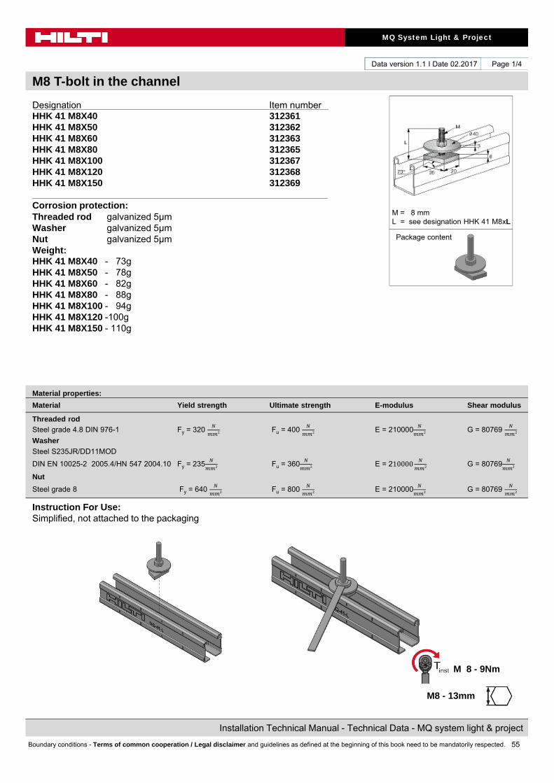
M8 T-bolt in the channel
Page 1/4
Designation Item numberHHK 41 M8X40 312361HHK 41 M8X50 312362HHK 41 M8X60 312363HHK 41 M8X80 312365HHK 41 M8X100 312367HHK 41 M8X120 312368HHK 41 M8X150 312369
Corrosion protection:Threaded rod galvanized 5μmWasher galvanized 5μmNut galvanized 5μmWeight:HHK 41 M8X40 - 73gHHK 41 M8X50 - 78gHHK 41 M8X60 - 82gHHK 41 M8X80 - 88gHHK 41 M8X100 - 94gHHK 41 M8X120 -100gHHK 41 M8X150 - 110g
Instruction For Use:Simplified, not attached to the packaging
Material properties:
Material Yield strength Ultimate strength E-modulus Shear modulus
Threaded rod
Steel grade 4.8 DIN 976-1 Fy = 320 Fu = 400 E = 210000 G = 80769
Washer
Steel S235JR/DD11MOD
DIN EN 10025-2 2005.4/HN 547 2004.10 Fy = 235 Fu = 360 E = 210000
G = 80769
Nut
Steel grade 8 Fy = 640 Fu = 800 E = 210000
G = 80769
M = 8 mmL = see designation HHK 41 M8xL
Package content
M 8 - 9Nm
M8 - 13mm

56
MQ System Light & Project
Installation Technical Manual - Technical Data - MQ system light & project
Boundary conditions - Terms of common cooperation / Legal disclaimer and guidelines as defined at the beginning of this book need to be mandatorily respected.
Data version 1.1 I Date 02.2017
M8 T-bolt in the channel
Page 2/4
Possible loading cases
Standard
Design criteria used for loading capacity
Methodology:
• Finite element analysis
• Standards and codes:• EN 1990 Basics of structural design 03.2003• EN 1991-1-1 Eurocode 1: Actions on structures – Part 1-1: General
actions – densities, self-weight, imposed loads for buildings 09.2011• EN 1993-1-1 Eurocode 3: Design of steel structures – Part 1-1: General
rules and rules for buildings 03.2012• EN 1993-1-3 Eurocode 3: Design of steel structures – Part 1-3: General
rules- Supplementary rules for cold-formed members andsheeting 03.2012
• EN 1993-1-5 Eurocode 3: Design of steel structures – Part 1-5: Platedstructural elements 03.2012
• EN 1993-1-8 Eurocode 3: Design of steel structures – Part 1-8: Design ofjoints 03.2012
• EN 10025-2 Hot rolled products of structural steels- Part 2: technical delivery conditions for non-alloy structural steels 02.2005
• RAL-GZ 655 Pipe Supports 04.2008
Software:
• Ansys 16.0• Microsoft Excel
Environmental conditions: • static loads• no fatigue loads
Simplified drawing:
M = 8 mmL = see designation HHK 41 M8xL

57
MQ System Light & Project
Installation Technical Manual - Technical Data - MQ system light & project
Boundary conditions - Terms of common cooperation / Legal disclaimer and guidelines as defined at the beginning of this book need to be mandatorily respected.
Data version 1.1 I Date 02.2017
M8 T-bolt in the channel
Page 3/4
Loading case: Standard Combinations covered by loading case
BOM:1x HHKHHK 41 M8X40 312361HHK 41 M8X50 312362HHK 41 M8X60 312363HHK 41 M8X80 312365HHK 41 M8X100 312365HHK 41 M8X120 312367HHK 41 M8X150 312368
Threaded bolt connection into a channel using simple channel nut, large washer and nut
Recommended loading capacity - simplified for most common applications
Method
Design loading capacity - 3D
Method
Limiting components of capacity evaluated in following tables:
1. T-bolt
±Fx,rec. [kN]
±Fy,rec. [kN]
±Fz,rec. [kN]
2.50
These values are individual one directional maximal capacity limits. For any combinations of multiple directions, use design values and their corresponding interaction formulas.
1/2
Possible loading cases
Standard
z
xy
58
MQ System Light & Project
Installation Technical Manual - Technical Data - MQ system light & project
Boundary conditions - Terms of common cooperation / Legal disclaimer and guidelines as defined at the beginning of this book need to be mandatorily respected.
Data version 1.1 I Date 02.2017
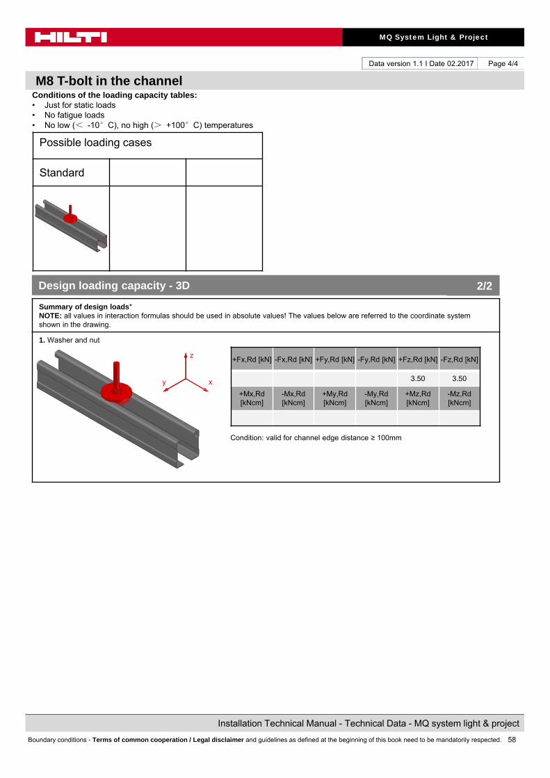
M8 T-bolt in the channel
Page 4/4
Conditions of the loading capacity tables:• Just for static loads• No fatigue loads• No low (< -10°C), no high (> +100°C) temperatures
Summary of design loads*NOTE: all values in interaction formulas should be used in absolute values! The values below are referred to the coordinate system shown in the drawing.
1. Washer and nut
Condition: valid for channel edge distance ≥ 100mm
+Fx,Rd [kN] -Fx,Rd [kN] +Fy,Rd [kN] -Fy,Rd [kN] +Fz,Rd [kN] -Fz,Rd [kN]
3.50 3.50
+Mx,Rd[kNcm]
-Mx,Rd[kNcm]
+My,Rd[kNcm]
-My,Rd[kNcm]
+Mz,Rd[kNcm]
-Mz,Rd[kNcm]
Design loading capacity - 3D 2/2
Possible loading cases
Standard
z
xy
59
MQ System Light & Project
Installation Technical Manual - Technical Data - MQ system light & project
Boundary conditions - Terms of common cooperation / Legal disclaimer and guidelines as defined at the beginning of this book need to be mandatorily respected.
Data version 1.1 I Date 02.2017
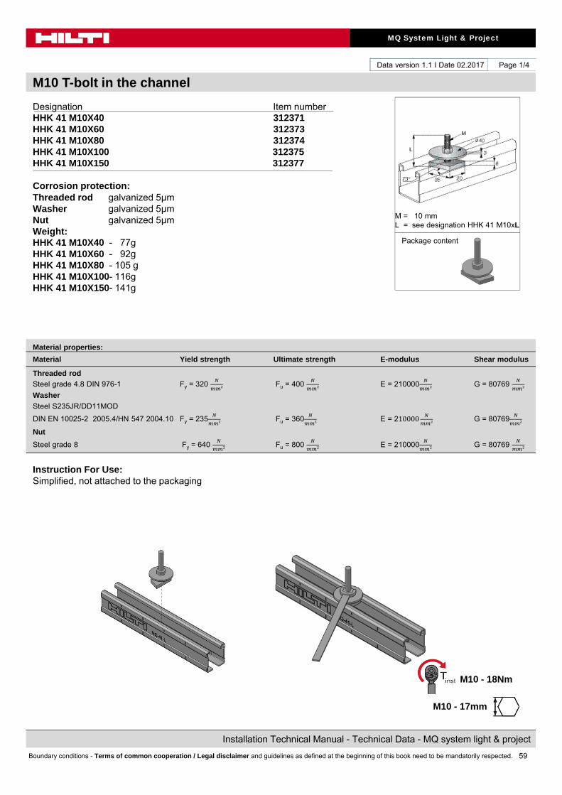
M10 T-bolt in the channel
Page 1/4
Designation Item numberHHK 41 M10X40 312371HHK 41 M10X60 312373HHK 41 M10X80 312374HHK 41 M10X100 312375HHK 41 M10X150 312377
Corrosion protection:Threaded rod galvanized 5μmWasher galvanized 5μmNut galvanized 5μmWeight:HHK 41 M10X40 - 77g HHK 41 M10X60 - 92gHHK 41 M10X80 - 105 gHHK 41 M10X100- 116gHHK 41 M10X150- 141g
Instruction For Use:Simplified, not attached to the packaging
Material properties:
Material Yield strength Ultimate strength E-modulus Shear modulus
Threaded rod
Steel grade 4.8 DIN 976-1 Fy = 320 Fu = 400 E = 210000 G = 80769
Washer
Steel S235JR/DD11MOD
DIN EN 10025-2 2005.4/HN 547 2004.10 Fy = 235 Fu = 360 E = 210000
G = 80769
Nut
Steel grade 8 Fy = 640 Fu = 800 E = 210000
G = 80769
M = 10 mmL = see designation HHK 41 M10xL
Package content
M10 - 18Nm
M10 - 17mm
60
MQ System Light & Project
Installation Technical Manual - Technical Data - MQ system light & project
Boundary conditions - Terms of common cooperation / Legal disclaimer and guidelines as defined at the beginning of this book need to be mandatorily respected.
Data version 1.1 I Date 02.2017
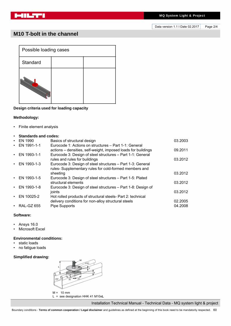
M10 T-bolt in the channel
Page 2/4
Possible loading cases
Standard
Design criteria used for loading capacity
Methodology:
• Finite element analysis
• Standards and codes:• EN 1990 Basics of structural design 03.2003• EN 1991-1-1 Eurocode 1: Actions on structures – Part 1-1: General
actions – densities, self-weight, imposed loads for buildings 09.2011• EN 1993-1-1 Eurocode 3: Design of steel structures – Part 1-1: General
rules and rules for buildings 03.2012• EN 1993-1-3 Eurocode 3: Design of steel structures – Part 1-3: General
rules- Supplementary rules for cold-formed members andsheeting 03.2012
• EN 1993-1-5 Eurocode 3: Design of steel structures – Part 1-5: Platedstructural elements 03.2012
• EN 1993-1-8 Eurocode 3: Design of steel structures – Part 1-8: Design ofjoints 03.2012
• EN 10025-2 Hot rolled products of structural steels- Part 2: technical delivery conditions for non-alloy structural steels 02.2005
• RAL-GZ 655 Pipe Supports 04.2008
Software:
• Ansys 16.0• Microsoft Excel
Environmental conditions: • static loads• no fatigue loads
Simplified drawing:
M = 10 mmL = see designation HHK 41 M10xL
61
MQ System Light & Project
Installation Technical Manual - Technical Data - MQ system light & project
Boundary conditions - Terms of common cooperation / Legal disclaimer and guidelines as defined at the beginning of this book need to be mandatorily respected.
Data version 1.1 I Date 02.2017
M10 T-bolt in the channel
Page 3/4
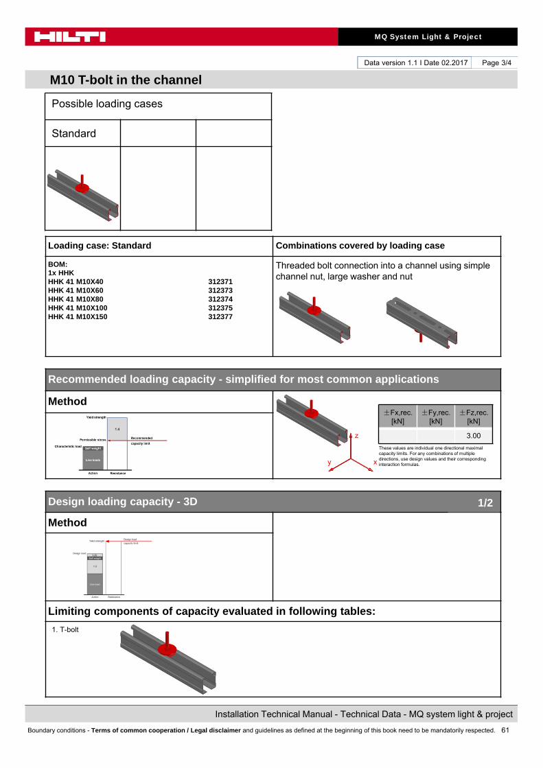
Loading case: Standard Combinations covered by loading case
BOM:1x HHKHHK 41 M10X40 312371HHK 41 M10X60 312373HHK 41 M10X80 312374HHK 41 M10X100 312375HHK 41 M10X150 312377
Threaded bolt connection into a channel using simple channel nut, large washer and nut
Recommended loading capacity - simplified for most common applications
Method
Design loading capacity - 3D
Method
Limiting components of capacity evaluated in following tables:
1. T-bolt
±Fx,rec. [kN]
±Fy,rec. [kN]
±Fz,rec. [kN]
3.00
These values are individual one directional maximal capacity limits. For any combinations of multiple directions, use design values and their corresponding interaction formulas.
1/2
Possible loading cases
Standard
z
xy

62
MQ System Light & Project
Installation Technical Manual - Technical Data - MQ system light & project
Boundary conditions - Terms of common cooperation / Legal disclaimer and guidelines as defined at the beginning of this book need to be mandatorily respected.
Data version 1.1 I Date 02.2017
M10 T-bolt in the channel
Page 4/4
Conditions of the loading capacity tables:• Just for static loads• No fatigue loads• No low (< -10°C), no high (> +100°C) temperatures
Summary of design loads*NOTE: all values in interaction formulas should be used in absolute values! The values below are referred to the coordinate system shown in the drawing.
1. Washer and nut
Condition: valid for channel edge distance ≥ 100mm
+Fx,Rd [kN] -Fx,Rd [kN] +Fy,Rd [kN] -Fy,Rd [kN] +Fz,Rd [kN] -Fz,Rd [kN]
4.20 4.20
+Mx,Rd[kNcm]
-Mx,Rd[kNcm]
+My,Rd[kNcm]
-My,Rd[kNcm]
+Mz,Rd[kNcm]
-Mz,Rd[kNcm]
Design loading capacity - 3D 2/2
Possible loading cases
Standard
z
xy
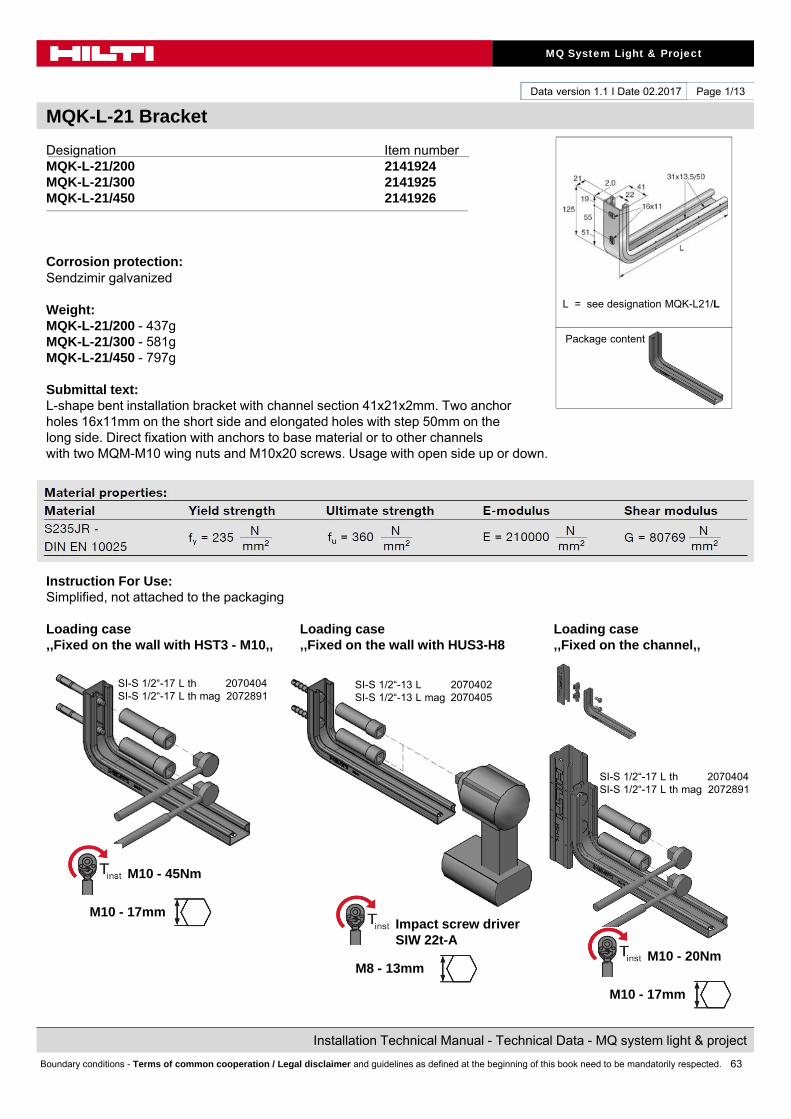
63
MQ System Light & Project
Installation Technical Manual - Technical Data - MQ system light & project
Boundary conditions - Terms of common cooperation / Legal disclaimer and guidelines as defined at the beginning of this book need to be mandatorily respected.
Data version 1.1 I Date 02.2017
MQK-L-21 Bracket
Page 1/13
Designation Item numberMQK-L-21/200 2141924MQK-L-21/300 2141925MQK-L-21/450 2141926
Corrosion protection:Sendzimir galvanized
Weight:MQK-L-21/200 - 437gMQK-L-21/300 - 581gMQK-L-21/450 - 797g
Submittal text:L-shape bent installation bracket with channel section 41x21x2mm. Two anchor holes 16x11mm on the short side and elongated holes with step 50mm on the long side. Direct fixation with anchors to base material or to other channels with two MQM-M10 wing nuts and M10x20 screws. Usage with open side up or down.
Instruction For Use:Simplified, not attached to the packaging
Loading case Loading case Loading case,,Fixed on the wall with HST3 - M10,, ,,Fixed on the wall with HUS3-H8 ,,Fixed on the channel,,
L = see designation MQK-L21/L
Package content
M10 - 20Nm
M10 - 17mm
SI-S 1/2“-13 L 2070402SI-S 1/2“-13 L mag 2070405
SI-S 1/2“-17 L th 2070404SI-S 1/2“-17 L th mag 2072891
SI-S 1/2“-17 L th 2070404SI-S 1/2“-17 L th mag 2072891
Impact screw driverSIW 22t-A
M10 - 45Nm
M10 - 17mm
M8 - 13mm
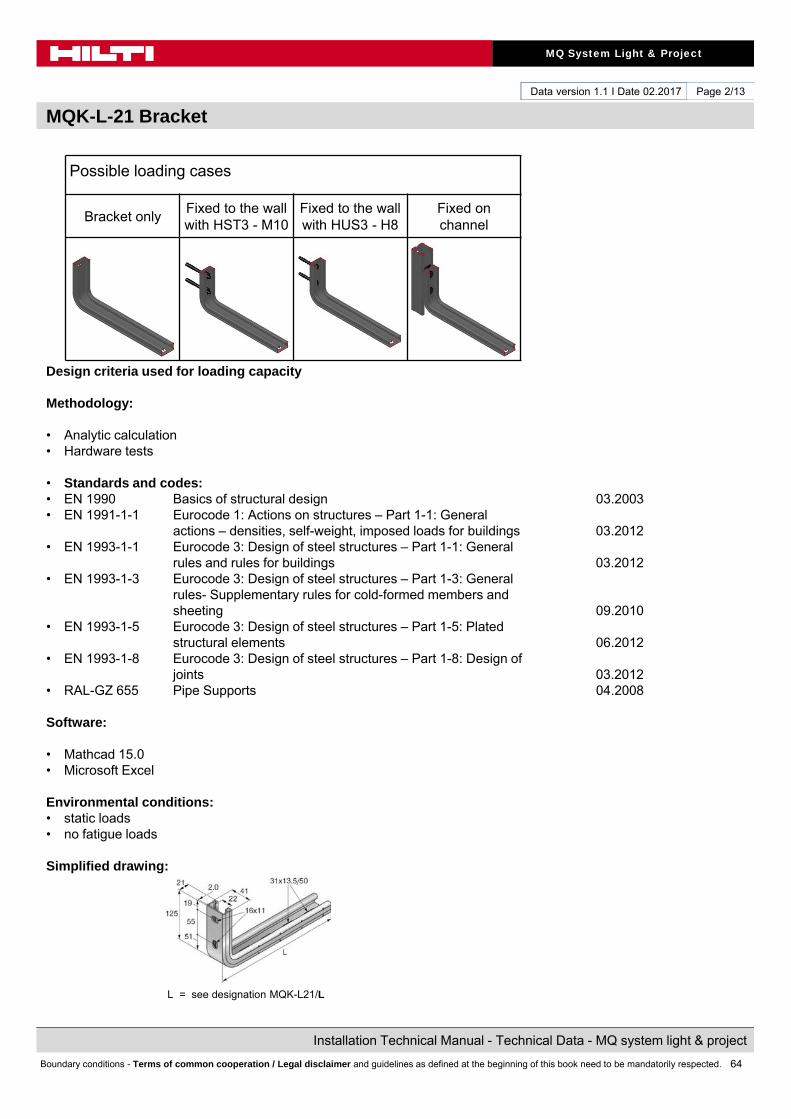
64
MQ System Light & Project
Installation Technical Manual - Technical Data - MQ system light & project
Boundary conditions - Terms of common cooperation / Legal disclaimer and guidelines as defined at the beginning of this book need to be mandatorily respected.
Data version 1.1 I Date 02.2017
MQK-L-21 Bracket
Page 2/13
Possible loading cases
Bracket onlyFixed to the wall with HST3 - M10
Fixed to the wall with HUS3 - H8
Fixed on channel
Design criteria used for loading capacity
Methodology:
• Analytic calculation• Hardware tests
• Standards and codes:• EN 1990 Basics of structural design 03.2003• EN 1991-1-1 Eurocode 1: Actions on structures – Part 1-1: General
actions – densities, self-weight, imposed loads for buildings 03.2012• EN 1993-1-1 Eurocode 3: Design of steel structures – Part 1-1: General
rules and rules for buildings 03.2012• EN 1993-1-3 Eurocode 3: Design of steel structures – Part 1-3: General
rules- Supplementary rules for cold-formed members andsheeting 09.2010
• EN 1993-1-5 Eurocode 3: Design of steel structures – Part 1-5: Platedstructural elements 06.2012
• EN 1993-1-8 Eurocode 3: Design of steel structures – Part 1-8: Design ofjoints 03.2012
• RAL-GZ 655 Pipe Supports 04.2008
Software:
• Mathcad 15.0• Microsoft Excel
Environmental conditions: • static loads• no fatigue loads
Simplified drawing:
L = see designation MQK-L21/L
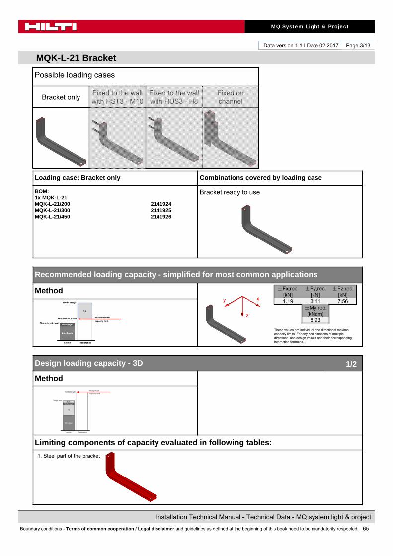
65
MQ System Light & Project
Installation Technical Manual - Technical Data - MQ system light & project
Boundary conditions - Terms of common cooperation / Legal disclaimer and guidelines as defined at the beginning of this book need to be mandatorily respected.
Data version 1.1 I Date 02.2017
MQK-L-21 Bracket
Page 3/13
Loading case: Bracket only Combinations covered by loading case
BOM:1x MQK-L-21MQK-L-21/200 2141924MQK-L-21/300 2141925MQK-L-21/450 2141926
Bracket ready to use
Recommended loading capacity - simplified for most common applications
Method
Design loading capacity - 3D
Method
Limiting components of capacity evaluated in following tables:
1. Steel part of the bracket
±Fx,rec. [kN]
±Fy,rec. [kN]
±Fz,rec. [kN]
1.19 3.11 7.56±My,rec.
[kNcm]8.93
These values are individual one directional maximal capacity limits. For any combinations of multiple directions, use design values and their corresponding interaction formulas.
1/2
Possible loading cases
Bracket onlyFixed to the wall with HST3 - M10
Fixed to the wall with HUS3 - H8
Fixed on channel
z
y x

66
MQ System Light & Project
Installation Technical Manual - Technical Data - MQ system light & project
Boundary conditions - Terms of common cooperation / Legal disclaimer and guidelines as defined at the beginning of this book need to be mandatorily respected.
Data version 1.1 I Date 02.2017
MQK-L-21 Bracket
Page 4/13
Conditions of the loading capacity tables:• Just for static loads• No fatigue loads• No low (< -10°C), no high (> +100°C) temperatures
Summary of design loads*NOTE: all values in interaction formulas should be used in absolute values! The values below are referred to the coordinate system shown in the drawing.
1. Steel part of the bracket
Interaction:
+Fx,Rd [kN] -Fx,Rd [kN] +Fy,Rd [kN] -Fy,Rd [kN] +Fz,Rd [kN] -Fz,Rd [kN]
1.66 2.41 4.35 4.35 10.58 10.58
+Mx,Rd[kNcm]
-Mx,Rd[kNcm]
+My,Rd[kNcm]
-My,Rd[kNcm]
+Mz,Rd[kNcm]
-Mz,Rd[kNcm]
1.04 1.04 12.50 12.50 1.04 1.04
Design loading capacity - 3D 2/2
Possible loading cases
Bracket onlyFixed to the wall with HST3 - M10
Fixed to the wall with HUS3 - H8
Fixed on channel
z
y x
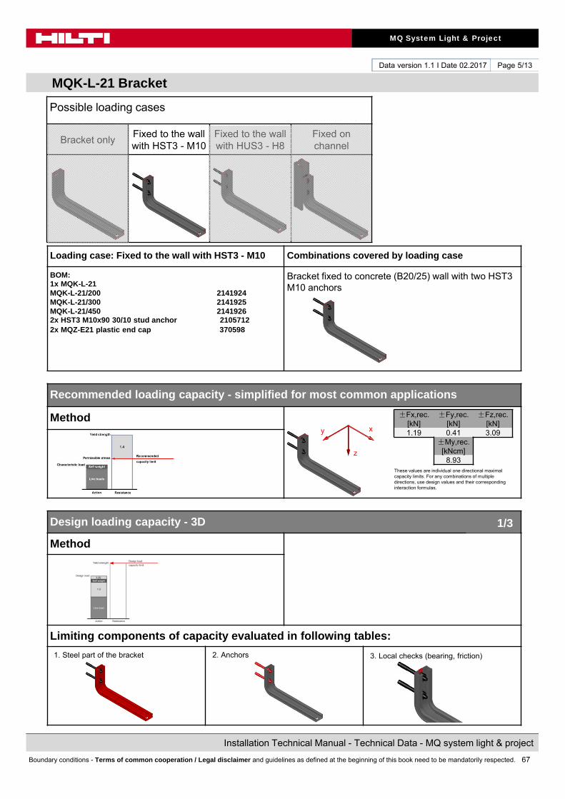
67
MQ System Light & Project
Installation Technical Manual - Technical Data - MQ system light & project
Boundary conditions - Terms of common cooperation / Legal disclaimer and guidelines as defined at the beginning of this book need to be mandatorily respected.
Data version 1.1 I Date 02.2017
MQK-L-21 Bracket
Page 5/13
Loading case: Fixed to the wall with HST3 - M10 Combinations covered by loading case
BOM:1x MQK-L-21MQK-L-21/200 2141924MQK-L-21/300 2141925MQK-L-21/450 21419262x HST3 M10x90 30/10 stud anchor 21057122x MQZ-E21 plastic end cap 370598
Bracket fixed to concrete (B20/25) wall with two HST3 M10 anchors
Recommended loading capacity - simplified for most common applications
Method
Design loading capacity - 3D
Method
Limiting components of capacity evaluated in following tables:
1. Steel part of the bracket
These values are individual one directional maximal capacity limits. For any combinations of multiple directions, use design values and their corresponding interaction formulas.
1/3
2. Anchors 3. Local checks (bearing, friction)
Possible loading cases
Bracket onlyFixed to the wall with HST3 - M10
Fixed to the wall with HUS3 - H8
Fixed on channel
±Fx,rec. [kN]
±Fy,rec. [kN]
±Fz,rec. [kN]
1.19 0.41 3.09±My,rec.
[kNcm]8.93
z
y x

68
MQ System Light & Project
Installation Technical Manual - Technical Data - MQ system light & project
Boundary conditions - Terms of common cooperation / Legal disclaimer and guidelines as defined at the beginning of this book need to be mandatorily respected.
Data version 1.1 I Date 02.2017
MQK-L-21 Bracket
Page 6/13
Conditions of the loading capacity tables:• Just for static loads• No fatigue loads• No low (< -10°C), no high (> +100°C) temperatures
Summary of design loads*NOTE: all values in interaction formulas should be used in absolute values! The values below are referred to the coordinate system shown in the drawing.
1. Steel part of the bracket
Interaction:
2. Anchors
Note: For load cases Fy and Mx, also the anchor in slotted hole parallel to force must be statically considered.If slotted hole is not filled with dynamic set, additional deformation occur on connector to overcome slotted hole. Otherwise for unfilled holes refer to values shown in 3) which consider friction between washer and channel.
+Fx,Rd [kN] -Fx,Rd [kN] +Fy,Rd [kN] -Fy,Rd [kN] +Fz,Rd [kN] -Fz,Rd [kN]
1.66 2.41 4.35 4.35 10.58 10.58
+Mx,Rd[kNcm]
-Mx,Rd[kNcm]
+My,Rd[kNcm]
-My,Rd[kNcm]
+Mz,Rd[kNcm]
-Mz,Rd[kNcm]
1.04 1.04 12.50 12.50 1.04 1.04
Design loading capacity - 3D 2/3
+Fx,Rd [kN] -Fx,Rd [kN] +Fy,Rd [kN] -Fy,Rd [kN] +Fz,Rd [kN] -Fz,Rd [kN]
3.50 9.00 10.00 10.00 16.00 16.00
+Mx,Rd[kNcm]
-Mx,Rd[kNcm]
+My,Rd[kNcm]
-My,Rd[kNcm]
+Mz,Rd[kNcm]
-Mz,Rd[kNcm]
90.00 90.00 48.00 45.00 11.75 11.75
Possible loading cases
Bracket onlyFixed to the wall with HST3 - M10
Fixed to the wall with HUS3 - H8
Fixed on channel
z
y x
z
y x

69
MQ System Light & Project
Installation Technical Manual - Technical Data - MQ system light & project
Boundary conditions - Terms of common cooperation / Legal disclaimer and guidelines as defined at the beginning of this book need to be mandatorily respected.
Data version 1.1 I Date 02.2017
MQK-L-21 Bracket
Page 7/13
Summary of design loads*NOTE: all values in interaction formulas should be used in absolute values! The values below are referred to the coordinate system shown in the drawing.
3. Local checks (bearing, friction)
Interaction:
Interaction:
+Fx,Rd[kN]
-Fx,Rd[kN]
+Fy,Rd[kN]
-Fy,Rd[kN]
+Fz,Rd[kN]
-Fz,Rd[kN]
Not decisive
Not decisive
0.57 0.57 4.32 7.92
+Mx,Rd[kNcm]
-Mx,Rd[kNcm]
+My,Rd[kNcm]
-My,Rd[kNcm]
+Mz,Rd[kNcm]
-Mz,Rd[kNcm]
2.29 2.29Not
deceiveNot
decisiveNot
decisiveNot
decisive
Design loading capacity - 3D 3/3
z
y x
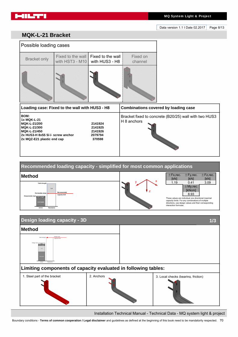
70
MQ System Light & Project
Installation Technical Manual - Technical Data - MQ system light & project
Boundary conditions - Terms of common cooperation / Legal disclaimer and guidelines as defined at the beginning of this book need to be mandatorily respected.
Data version 1.1 I Date 02.2017
MQK-L-21 Bracket
Page 8/13
Loading case: Fixed to the wall with HUS3 - H8 Combinations covered by loading case
BOM:1x MQK-L-21MQK-L-21/200 2141924MQK-L-21/300 2141925MQK-L-21/450 21419262x HUS3-H 8x55 5/-/- screw anchor 20797942x MQZ-E21 plastic end cap 370598
Bracket fixed to concrete (B20/25) wall with two HUS3 H 8 anchors
Recommended loading capacity - simplified for most common applications
Method
Design loading capacity - 3D
Method
Limiting components of capacity evaluated in following tables:
1. Steel part of the bracket
These values are individual one directional maximal capacity limits. For any combinations of multiple directions, use design values and their corresponding interaction formulas.
1/3
2. Anchors 3. Local checks (bearing, friction)
Possible loading cases
Bracket onlyFixed to the wall with HST3 - M10
Fixed to the wall with HUS3 - H8
Fixed on channel
±Fx,rec. [kN]
±Fy,rec. [kN]
±Fz,rec. [kN]
1.19 0.41 3.09±My,rec.
[kNcm]8.93
z
y x
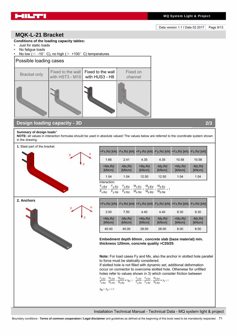
71
MQ System Light & Project
Installation Technical Manual - Technical Data - MQ system light & project
Boundary conditions - Terms of common cooperation / Legal disclaimer and guidelines as defined at the beginning of this book need to be mandatorily respected.
Data version 1.1 I Date 02.2017
MQK-L-21 Bracket
Page 9/13
Conditions of the loading capacity tables:• Just for static loads• No fatigue loads• No low (< -10°C), no high (> +100°C) temperatures
Summary of design loads*NOTE: all values in interaction formulas should be used in absolute values! The values below are referred to the coordinate system shown in the drawing.
1. Steel part of the bracket
Interaction:
2. Anchors
Embedment depth 60mm , concrete slab (base material) min.thickness 120mm, concrete quality >C20/25
Note: For load cases Fy and Mx, also the anchor in slotted hole parallel to force must be statically considered.If slotted hole is not filled with dynamic set, additional deformation occur on connector to overcome slotted hole. Otherwise for unfilled holes refer to values shown in 3) which consider friction between washer and channel.
+Fx,Rd [kN] -Fx,Rd [kN] +Fy,Rd [kN] -Fy,Rd [kN] +Fz,Rd [kN] -Fz,Rd [kN]
1.66 2.41 4.35 4.35 10.58 10.58
+Mx,Rd[kNcm]
-Mx,Rd[kNcm]
+My,Rd[kNcm]
-My,Rd[kNcm]
+Mz,Rd[kNcm]
-Mz,Rd[kNcm]
1.04 1.04 12.50 12.50 1.04 1.04
Design loading capacity - 3D 2/3
+Fx,Rd [kN] -Fx,Rd [kN] +Fy,Rd [kN] -Fy,Rd [kN] +Fz,Rd [kN] -Fz,Rd [kN]
3.00 7.50 4.40 4.40 8.30 8.30
+Mx,Rd[kNcm]
-Mx,Rd[kNcm]
+My,Rd[kNcm]
-My,Rd[kNcm]
+Mz,Rd[kNcm]
-Mz,Rd[kNcm]
40.00 40.00 29.00 28.00 8.00 8.00
Possible loading cases
Bracket onlyFixed to the wall with HST3 - M10
Fixed to the wall with HUS3 - H8
Fixed on channel
z
y x
z
y x
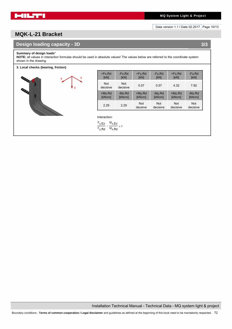
72
MQ System Light & Project
Installation Technical Manual - Technical Data - MQ system light & project
Boundary conditions - Terms of common cooperation / Legal disclaimer and guidelines as defined at the beginning of this book need to be mandatorily respected.
Data version 1.1 I Date 02.2017
MQK-L-21 Bracket
Page 10/13
Summary of design loads*NOTE: all values in interaction formulas should be used in absolute values! The values below are referred to the coordinate system shown in the drawing.
3. Local checks (bearing, friction)
Interaction:
Interaction:
+Fx,Rd[kN]
-Fx,Rd[kN]
+Fy,Rd[kN]
-Fy,Rd[kN]
+Fz,Rd[kN]
-Fz,Rd[kN]
Not decisive
Not decisive
0.57 0.57 4.32 7.92
+Mx,Rd[kNcm]
-Mx,Rd[kNcm]
+My,Rd[kNcm]
-My,Rd[kNcm]
+Mz,Rd[kNcm]
-Mz,Rd[kNcm]
2.29 2.29Not
deceiveNot
decisiveNot
decisiveNot
decisive
Design loading capacity - 3D 3/3
z
y x
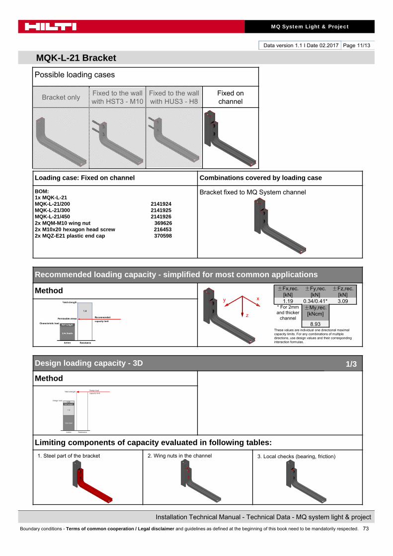
73
MQ System Light & Project
Installation Technical Manual - Technical Data - MQ system light & project
Boundary conditions - Terms of common cooperation / Legal disclaimer and guidelines as defined at the beginning of this book need to be mandatorily respected.
Data version 1.1 I Date 02.2017
MQK-L-21 Bracket
Page 11/13
Loading case: Fixed on channel Combinations covered by loading case
BOM:1x MQK-L-21MQK-L-21/200 2141924MQK-L-21/300 2141925MQK-L-21/450 21419262x MQM-M10 wing nut 3696262x M10x20 hexagon head screw 2164532x MQZ-E21 plastic end cap 370598
Bracket fixed to MQ System channel
Recommended loading capacity - simplified for most common applications
Method
Design loading capacity - 3D
Method
Limiting components of capacity evaluated in following tables:
1. Steel part of the bracket
These values are individual one directional maximal capacity limits. For any combinations of multiple directions, use design values and their corresponding interaction formulas.
1/3
2. Wing nuts in the channel 3. Local checks (bearing, friction)
Possible loading cases
Bracket onlyFixed to the wall with HST3 - M10
Fixed to the wall with HUS3 - H8
Fixed on channel
±Fx,rec. [kN]
±Fy,rec. [kN]
±Fz,rec. [kN]
1.19 0.34/0.41* 3.09* For 2mm and thicker
channel
±My,rec. [kNcm]
8.93
z
y x
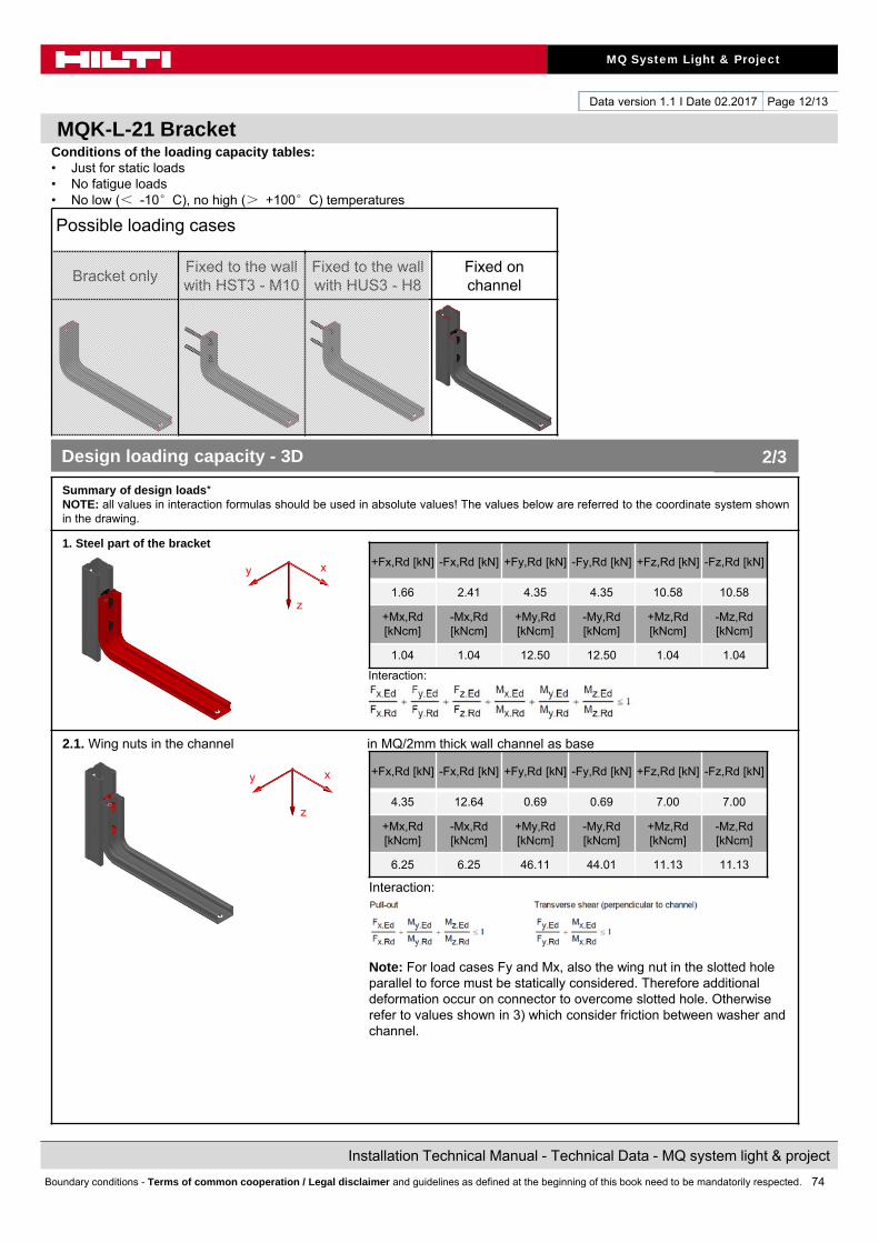
74
MQ System Light & Project
Installation Technical Manual - Technical Data - MQ system light & project
Boundary conditions - Terms of common cooperation / Legal disclaimer and guidelines as defined at the beginning of this book need to be mandatorily respected.
Data version 1.1 I Date 02.2017
MQK-L-21 Bracket
Page 12/13
Conditions of the loading capacity tables:• Just for static loads• No fatigue loads• No low (< -10°C), no high (> +100°C) temperatures
Summary of design loads*NOTE: all values in interaction formulas should be used in absolute values! The values below are referred to the coordinate system shown in the drawing.
1. Steel part of the bracket
Interaction:
2.1. Wing nuts in the channel in MQ/2mm thick wall channel as base
Interaction:
Note: For load cases Fy and Mx, also the wing nut in the slotted hole parallel to force must be statically considered. Therefore additional deformation occur on connector to overcome slotted hole. Otherwise refer to values shown in 3) which consider friction between washer and channel.
+Fx,Rd [kN] -Fx,Rd [kN] +Fy,Rd [kN] -Fy,Rd [kN] +Fz,Rd [kN] -Fz,Rd [kN]
1.66 2.41 4.35 4.35 10.58 10.58
+Mx,Rd[kNcm]
-Mx,Rd[kNcm]
+My,Rd[kNcm]
-My,Rd[kNcm]
+Mz,Rd[kNcm]
-Mz,Rd[kNcm]
1.04 1.04 12.50 12.50 1.04 1.04
Design loading capacity - 3D 2/3
+Fx,Rd [kN] -Fx,Rd [kN] +Fy,Rd [kN] -Fy,Rd [kN] +Fz,Rd [kN] -Fz,Rd [kN]
4.35 12.64 0.69 0.69 7.00 7.00
+Mx,Rd[kNcm]
-Mx,Rd[kNcm]
+My,Rd[kNcm]
-My,Rd[kNcm]
+Mz,Rd[kNcm]
-Mz,Rd[kNcm]
6.25 6.25 46.11 44.01 11.13 11.13
Possible loading cases
Bracket onlyFixed to the wall with HST3 - M10
Fixed to the wall with HUS3 - H8
Fixed on channel
z
y x
z
y x
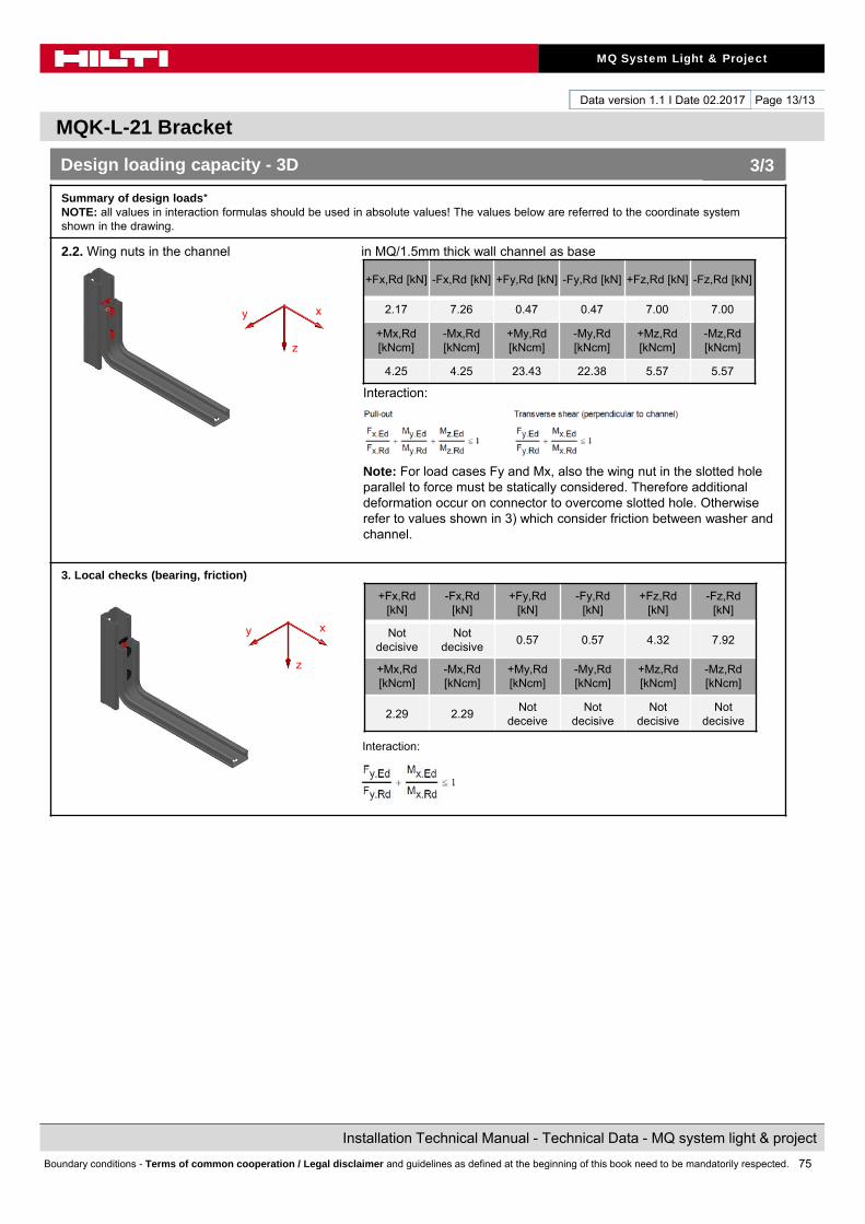
75
MQ System Light & Project
Installation Technical Manual - Technical Data - MQ system light & project
Boundary conditions - Terms of common cooperation / Legal disclaimer and guidelines as defined at the beginning of this book need to be mandatorily respected.
Data version 1.1 I Date 02.2017
MQK-L-21 Bracket
Page 13/13
Summary of design loads*NOTE: all values in interaction formulas should be used in absolute values! The values below are referred to the coordinate system shown in the drawing.
2.2. Wing nuts in the channel in MQ/1.5mm thick wall channel as base
Interaction:
Note: For load cases Fy and Mx, also the wing nut in the slotted hole parallel to force must be statically considered. Therefore additional deformation occur on connector to overcome slotted hole. Otherwise refer to values shown in 3) which consider friction between washer and channel.
3. Local checks (bearing, friction)
Interaction:
+Fx,Rd[kN]
-Fx,Rd[kN]
+Fy,Rd[kN]
-Fy,Rd[kN]
+Fz,Rd[kN]
-Fz,Rd[kN]
Not decisive
Not decisive
0.57 0.57 4.32 7.92
+Mx,Rd[kNcm]
-Mx,Rd[kNcm]
+My,Rd[kNcm]
-My,Rd[kNcm]
+Mz,Rd[kNcm]
-Mz,Rd[kNcm]
2.29 2.29Not
deceiveNot
decisiveNot
decisiveNot
decisive
Design loading capacity - 3D 3/3
+Fx,Rd [kN] -Fx,Rd [kN] +Fy,Rd [kN] -Fy,Rd [kN] +Fz,Rd [kN] -Fz,Rd [kN]
2.17 7.26 0.47 0.47 7.00 7.00
+Mx,Rd[kNcm]
-Mx,Rd[kNcm]
+My,Rd[kNcm]
-My,Rd[kNcm]
+Mz,Rd[kNcm]
-Mz,Rd[kNcm]
4.25 4.25 23.43 22.38 5.57 5.57
z
y x
z
y x
76
MQ System Light & Project
Installation Technical Manual - Technical Data - MQ system light & project
Boundary conditions - Terms of common cooperation / Legal disclaimer and guidelines as defined at the beginning of this book need to be mandatorily respected.

77
MQ System Light & Project
Installation Technical Manual - Technical Data - MQ system light & project
Boundary conditions - Terms of common cooperation / Legal disclaimer and guidelines as defined at the beginning of this book need to be mandatorily respected.
Data version 1.1 I Date 02.2017
HUS3-H8 Direct fixation to concrete
Page 1/6
Designation Item numberChannelMQ-21 2m 2148545MQ-21 3m 2148544MQ-21 6m 2148543MQ-41-L 2m 2141966MQ-41-L 3m 2141965MQ-41-L 6m 2141964Screw anchorHUS3 - H8x55 5/-/- screw anchor 2079794 Washer for loading case HUS-H8&W in channel slotA 10.5/20 washer 282851
Corrosion protection:Channel sendzimir galvanized average 10μmScrew anchor zinc plated min 5μm
Weight:Channel MQ-21 1430 g/mChannel MQ-41-L 1600 g/mAnchor 32.9 g
Instruction For Use:Simplified, not attached to the packagingLoading case ,,HUS3-H8 in anchor hole,, Loading case ,,HUS3-H8&W (and M10 washer) in
channel slot,,
Material properties:
Material Yield strength Ultimate strength E-modulus Shear modulus
Channel
Steel S250GD - DIN EN 10346 Fy = 290 Fu = 330 E = 210000 G = 80769
Anchor
Carbon steel Fy = 695 Fu = 810 E = 210000
G = 80769
Package content
bundledvarious
packages
SI-S 1/2“-13 L 2070402SI-S 1/2“-13 L mag 2070405
Impact screw driverSIW 22t-A
M8 - 13mm
SI-S 1/2“-13 L 2070402SI-S 1/2“-13 L mag 2070405
Impact screw driverSIW 22t-A
M8 - 13mm
HUS3 - H8x55 5/-/- screw anchor 2079794 A 10.5/20 washer 282851
HUS3 - H8x55 5/-/- screw anchor 2079794
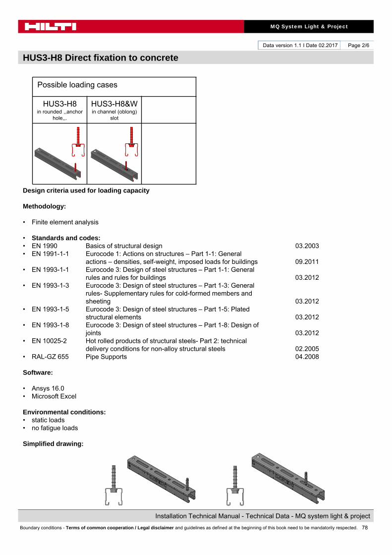
78
MQ System Light & Project
Installation Technical Manual - Technical Data - MQ system light & project
Boundary conditions - Terms of common cooperation / Legal disclaimer and guidelines as defined at the beginning of this book need to be mandatorily respected.
Data version 1.1 I Date 02.2017
HUS3-H8 Direct fixation to concrete
Page 2/6
Possible loading cases
HUS3-H8 in rounded ,,anchor
hole,,.
HUS3-H8&W in channel (oblong)
slot
Design criteria used for loading capacity
Methodology:
• Finite element analysis
• Standards and codes:• EN 1990 Basics of structural design 03.2003• EN 1991-1-1 Eurocode 1: Actions on structures – Part 1-1: General
actions – densities, self-weight, imposed loads for buildings 09.2011• EN 1993-1-1 Eurocode 3: Design of steel structures – Part 1-1: General
rules and rules for buildings 03.2012• EN 1993-1-3 Eurocode 3: Design of steel structures – Part 1-3: General
rules- Supplementary rules for cold-formed members andsheeting 03.2012
• EN 1993-1-5 Eurocode 3: Design of steel structures – Part 1-5: Platedstructural elements 03.2012
• EN 1993-1-8 Eurocode 3: Design of steel structures – Part 1-8: Design ofjoints 03.2012
• EN 10025-2 Hot rolled products of structural steels- Part 2: technical delivery conditions for non-alloy structural steels 02.2005
• RAL-GZ 655 Pipe Supports 04.2008
Software:
• Ansys 16.0• Microsoft Excel
Environmental conditions: • static loads• no fatigue loads
Simplified drawing:

79
MQ System Light & Project
Installation Technical Manual - Technical Data - MQ system light & project
Boundary conditions - Terms of common cooperation / Legal disclaimer and guidelines as defined at the beginning of this book need to be mandatorily respected.
Data version 1.1 I Date 02.2017
HUS3-H8 Direct fixation to concrete
Page 3/6
Loading case: HUS3-H8 in rounded ,,anchor hole,,. Combinations covered by loading case
BOM:ChannelChannelMQ-21 2m 2148545MQ-21 3m 2148544MQ-21 6m 2148543MQ-41-L 2m 2141966MQ-41-L 3m 2141965MQ-41-L 6m 2141964Screw anchorHUS3 - H8x55 5/-/- 2079794
Direct fixation of channel on concrete fixed by HUS3-H8 through ,,Anchor hole,, in the channel
Recommended loading capacity - simplified for most common applications
Method
Design loading capacity - 3D
Method
Limiting components of capacity evaluated in following tables:1. Channel local pull through
±Fx,rec. [kN]
±Fy,rec. [kN]
±Fz,rec. [kN]
3.14
These values are individual one directional maximal capacity limits. For any combinations of multiple directions, use design values and their corresponding interaction formulas.
1/2
Possible loading cases
HUS3-H8 in rounded ,,anchor
hole,,.
HUS3-H8&W in channel (oblong)
slot
z
xy

80
MQ System Light & Project
Installation Technical Manual - Technical Data - MQ system light & project
Boundary conditions - Terms of common cooperation / Legal disclaimer and guidelines as defined at the beginning of this book need to be mandatorily respected.
Data version 1.1 I Date 02.2017
HUS3-H8 Direct fixation to concrete
Page 4/6
Conditions of the loading capacity tables:• Just for static loads• No fatigue loads• No low (< -10°C), no high (> +100°C) temperatures
Summary of design loads*NOTE: all values in interaction formulas should be used in absolute values! The values below are referred to the coordinate system shown in the drawing.
1. Channel local pull through
Condition: valid for channel edge distance ≥ 100mm, min concrete quality C20/25, no edge influence, no other anchor distance influence,min concrete slab (base material) thickness 120mm
+Fx,Rd [kN] -Fx,Rd [kN] +Fy,Rd [kN] -Fy,Rd [kN] +Fz,Rd [kN] -Fz,Rd [kN]
4.40
+Mx,Rd[kNcm]
-Mx,Rd[kNcm]
+My,Rd[kNcm]
-My,Rd[kNcm]
+Mz,Rd[kNcm]
-Mz,Rd[kNcm]
Design loading capacity - 3D 2/2
Possible loading cases
HUS3-H8 in rounded ,,anchor
hole,,.
HUS3-H8&W in channel (oblong)
slot
z
xy

81
MQ System Light & Project
Installation Technical Manual - Technical Data - MQ system light & project
Boundary conditions - Terms of common cooperation / Legal disclaimer and guidelines as defined at the beginning of this book need to be mandatorily respected.
Data version 1.1 I Date 02.2017
HUS3-H8 Direct fixation to concrete
Page 5/6
Loading case: HUS3-H8&W in channel (oblong) slot Combinations covered by loading case
BOM:ChannelMQ-21 2m 2148545MQ-21 3m 2148544MQ-21 6m 2148543MQ-41-L 2m 2141966MQ-41-L 3m 2141965MQ-41-L 6m 2141964Screw anchorHUS3 - H8x55 5/-/- 2079794A 10.5/20 washer 282851
Direct fixation of channel on concrete fixed by HUS3-H8 and M10 washer through (oblong) slot in the channel
Recommended loading capacity - simplified for most common applications
Method
Design loading capacity - 3D
Method
Limiting components of capacity evaluated in following tables:1. Channel local pull through
±Fx,rec. [kN]
±Fy,rec. [kN]
±Fz,rec. [kN]
2.89
These values are individual one directional maximal capacity limits. For any combinations of multiple directions, use design values and their corresponding interaction formulas.
1/2
Possible loading cases
HUS3-H8 in rounded ,,anchor
hole,,.
HUS3-H8&W in channel (oblong)
slot
z
xy
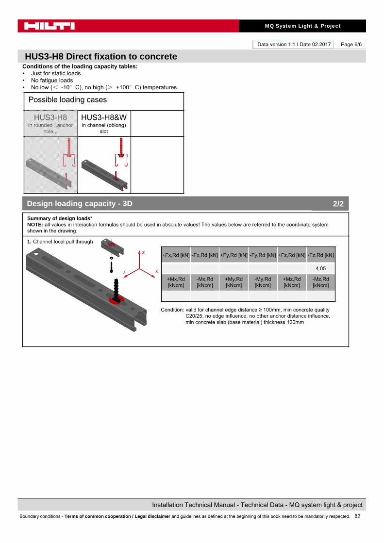
82
MQ System Light & Project
Installation Technical Manual - Technical Data - MQ system light & project
Boundary conditions - Terms of common cooperation / Legal disclaimer and guidelines as defined at the beginning of this book need to be mandatorily respected.
Data version 1.1 I Date 02.2017
HUS3-H8 Direct fixation to concrete
Page 6/6
Conditions of the loading capacity tables:• Just for static loads• No fatigue loads• No low (< -10°C), no high (> +100°C) temperatures
Summary of design loads*NOTE: all values in interaction formulas should be used in absolute values! The values below are referred to the coordinate system shown in the drawing.
1. Channel local pull through
Condition: valid for channel edge distance ≥ 100mm, min concrete quality C20/25, no edge influence, no other anchor distance influence,min concrete slab (base material) thickness 120mm
+Fx,Rd [kN] -Fx,Rd [kN] +Fy,Rd [kN] -Fy,Rd [kN] +Fz,Rd [kN] -Fz,Rd [kN]
4.05
+Mx,Rd[kNcm]
-Mx,Rd[kNcm]
+My,Rd[kNcm]
-My,Rd[kNcm]
+Mz,Rd[kNcm]
-Mz,Rd[kNcm]
Design loading capacity - 3D 2/2
Possible loading cases
HUS3-H8 in rounded ,,anchor
hole,,.
HUS3-H8&W in channel (oblong)
slot
z
xy
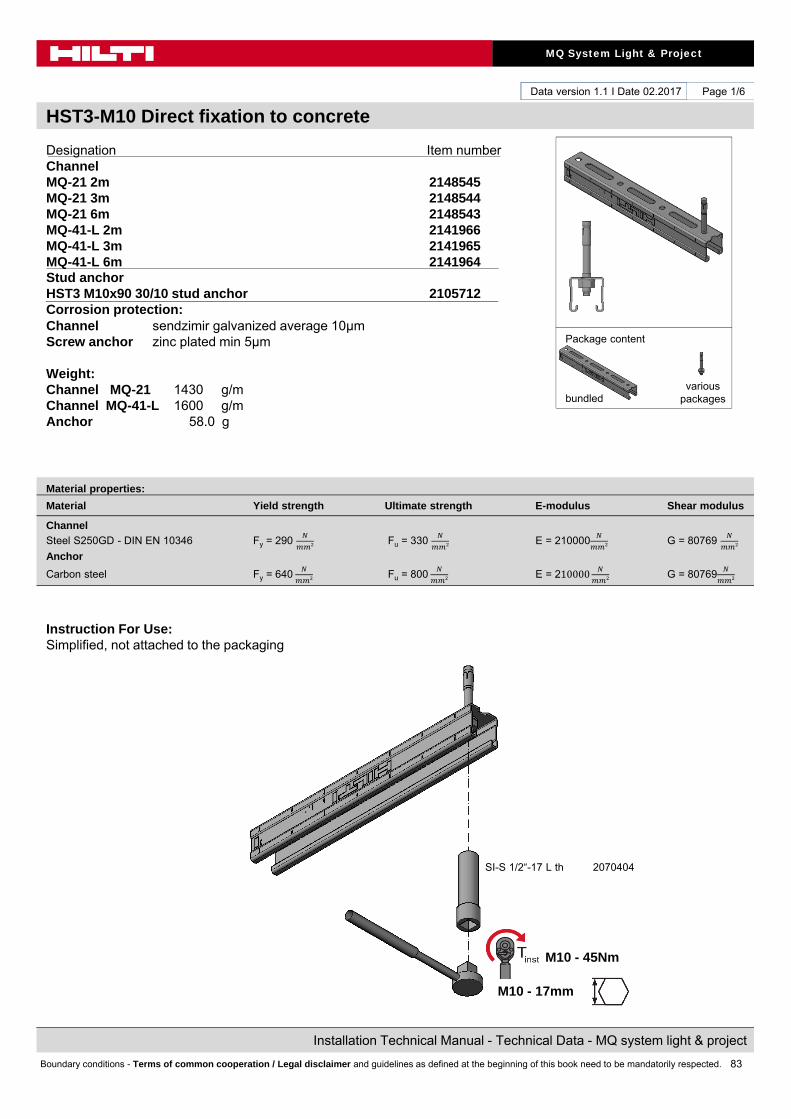
83
MQ System Light & Project
Installation Technical Manual - Technical Data - MQ system light & project
Boundary conditions - Terms of common cooperation / Legal disclaimer and guidelines as defined at the beginning of this book need to be mandatorily respected.
Data version 1.1 I Date 02.2017
HST3-M10 Direct fixation to concrete
Page 1/6
Designation Item numberChannelMQ-21 2m 2148545MQ-21 3m 2148544MQ-21 6m 2148543MQ-41-L 2m 2141966MQ-41-L 3m 2141965MQ-41-L 6m 2141964Stud anchorHST3 M10x90 30/10 stud anchor 2105712Corrosion protection:Channel sendzimir galvanized average 10μmScrew anchor zinc plated min 5μm
Weight:Channel MQ-21 1430 g/mChannel MQ-41-L 1600 g/mAnchor 58.0 g
Instruction For Use:Simplified, not attached to the packaging
Material properties:
Material Yield strength Ultimate strength E-modulus Shear modulus
Channel
Steel S250GD - DIN EN 10346 Fy = 290 Fu = 330 E = 210000 G = 80769
Anchor
Carbon steel Fy = 640 Fu = 800 E = 210000
G = 80769
Package content
bundledvarious
packages
SI-S 1/2“-17 L th 2070404
M10 - 45Nm
M10 - 17mm

84
MQ System Light & Project
Installation Technical Manual - Technical Data - MQ system light & project
Boundary conditions - Terms of common cooperation / Legal disclaimer and guidelines as defined at the beginning of this book need to be mandatorily respected.
Data version 1.1 I Date 02.2017
HST3-M10 Direct fixation to concrete
Page 2/6
Possible loading cases
HST3-M10 in rounded
,,anchor hole,,.
HST3-M10 in channel
(oblong) slot
Design criteria used for loading capacity
Methodology:
• Finite element analysis
• Standards and codes:• EN 1990 Basics of structural design 03.2003• EN 1991-1-1 Eurocode 1: Actions on structures – Part 1-1: General
actions – densities, self-weight, imposed loads for buildings 09.2011• EN 1993-1-1 Eurocode 3: Design of steel structures – Part 1-1: General
rules and rules for buildings 03.2012• EN 1993-1-3 Eurocode 3: Design of steel structures – Part 1-3: General
rules- Supplementary rules for cold-formed members andsheeting 03.2012
• EN 1993-1-5 Eurocode 3: Design of steel structures – Part 1-5: Platedstructural elements 03.2012
• EN 1993-1-8 Eurocode 3: Design of steel structures – Part 1-8: Design ofjoints 03.2012
• EN 10025-2 Hot rolled products of structural steels- Part 2: technical delivery conditions for non-alloy structural steels 02.2005
• RAL-GZ 655 Pipe Supports 04.2008
Software:
• Ansys 16.0• Microsoft Excel
Environmental conditions: • static loads• no fatigue loads
Simplified drawing:
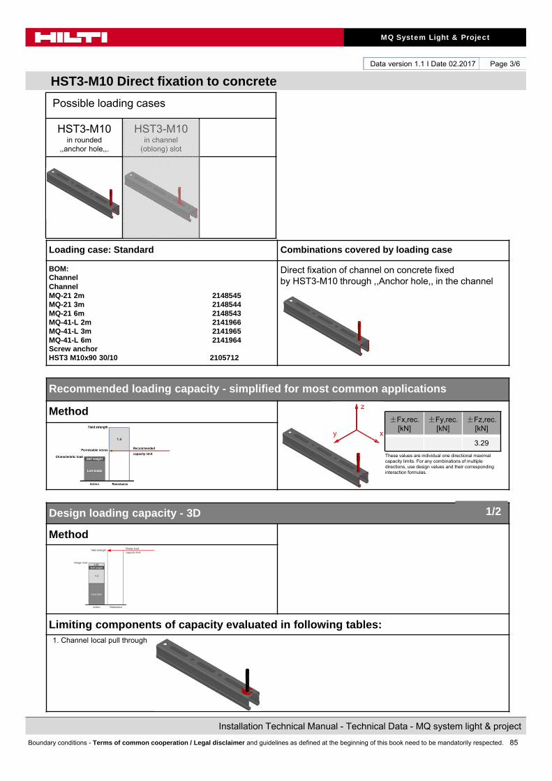
85
MQ System Light & Project
Installation Technical Manual - Technical Data - MQ system light & project
Boundary conditions - Terms of common cooperation / Legal disclaimer and guidelines as defined at the beginning of this book need to be mandatorily respected.
Data version 1.1 I Date 02.2017
HST3-M10 Direct fixation to concrete
Page 3/6
Loading case: Standard Combinations covered by loading case
BOM:ChannelChannelMQ-21 2m 2148545MQ-21 3m 2148544MQ-21 6m 2148543MQ-41-L 2m 2141966MQ-41-L 3m 2141965MQ-41-L 6m 2141964Screw anchorHST3 M10x90 30/10 2105712
Direct fixation of channel on concrete fixed by HST3-M10 through ,,Anchor hole,, in the channel
Recommended loading capacity - simplified for most common applications
Method
Design loading capacity - 3D
Method
Limiting components of capacity evaluated in following tables:1. Channel local pull through
±Fx,rec. [kN]
±Fy,rec. [kN]
±Fz,rec. [kN]
3.29
These values are individual one directional maximal capacity limits. For any combinations of multiple directions, use design values and their corresponding interaction formulas.
1/2
Possible loading cases
HST3-M10 in rounded
,,anchor hole,,.
HST3-M10 in channel
(oblong) slot
z
xy

86
MQ System Light & Project
Installation Technical Manual - Technical Data - MQ system light & project
Boundary conditions - Terms of common cooperation / Legal disclaimer and guidelines as defined at the beginning of this book need to be mandatorily respected.
Data version 1.1 I Date 02.2017
HUS3-H8 Direct fixation to concrete
Page 4/6
Conditions of the loading capacity tables:• Just for static loads• No fatigue loads• No low (< -10°C), no high (> +100°C) temperatures
Summary of design loads*NOTE: all values in interaction formulas should be used in absolute values! The values below are referred to the coordinate system shown in the drawing.
1. Channel local pull through
Condition: valid for channel edge distance ≥ 100mm, min concrete quality C20/25, no edge influence, no other anchor distance influence,min concrete slab (base material) thickness 120mm
+Fx,Rd [kN] -Fx,Rd [kN] +Fy,Rd [kN] -Fy,Rd [kN] +Fz,Rd [kN] -Fz,Rd [kN]
4.60
+Mx,Rd[kNcm]
-Mx,Rd[kNcm]
+My,Rd[kNcm]
-My,Rd[kNcm]
+Mz,Rd[kNcm]
-Mz,Rd[kNcm]
Design loading capacity - 3D 2/2
Possible loading cases
HST3-M10 in rounded
,,anchor hole,,.
HST3-M10 in channel
(oblong) slot
z
xy
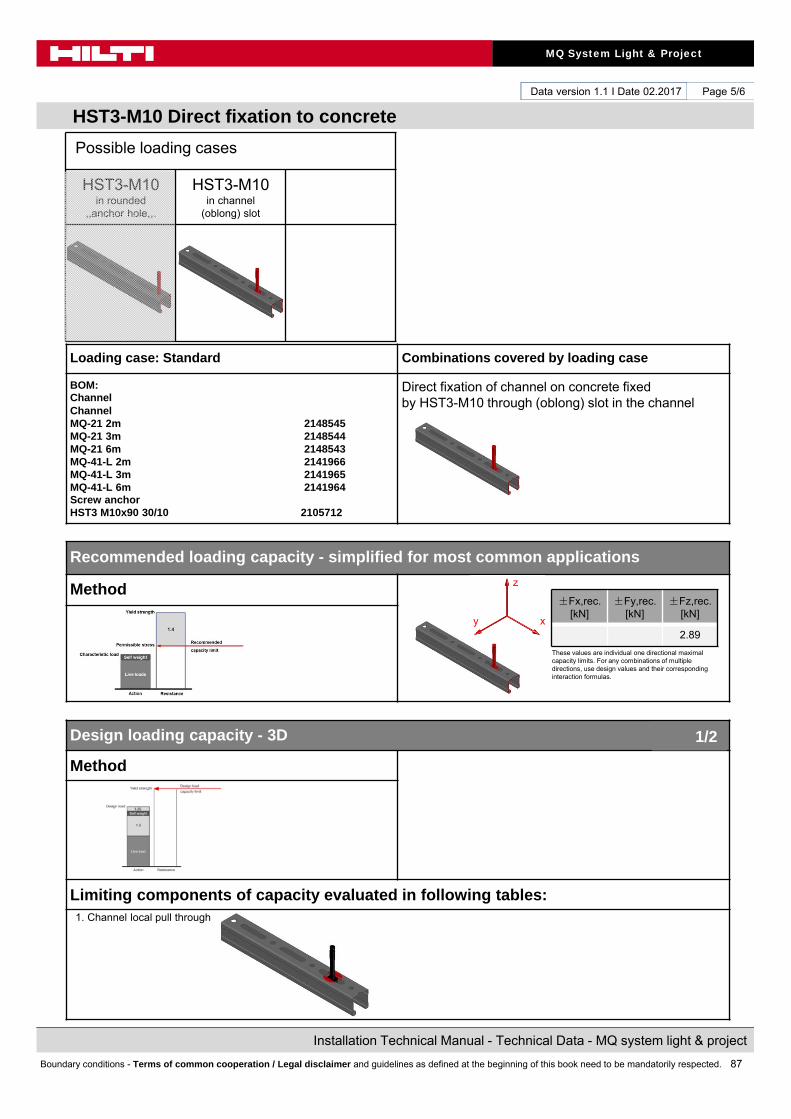
87
MQ System Light & Project
Installation Technical Manual - Technical Data - MQ system light & project
Boundary conditions - Terms of common cooperation / Legal disclaimer and guidelines as defined at the beginning of this book need to be mandatorily respected.
Data version 1.1 I Date 02.2017
HST3-M10 Direct fixation to concrete
Page 5/6
Loading case: Standard Combinations covered by loading case
BOM:ChannelChannelMQ-21 2m 2148545MQ-21 3m 2148544MQ-21 6m 2148543MQ-41-L 2m 2141966MQ-41-L 3m 2141965MQ-41-L 6m 2141964Screw anchorHST3 M10x90 30/10 2105712
Direct fixation of channel on concrete fixed by HST3-M10 through (oblong) slot in the channel
Recommended loading capacity - simplified for most common applications
Method
Design loading capacity - 3D
Method
Limiting components of capacity evaluated in following tables:1. Channel local pull through
±Fx,rec. [kN]
±Fy,rec. [kN]
±Fz,rec. [kN]
2.89
These values are individual one directional maximal capacity limits. For any combinations of multiple directions, use design values and their corresponding interaction formulas.
1/2
Possible loading cases
HST3-M10 in rounded
,,anchor hole,,.
HST3-M10 in channel
(oblong) slot
z
xy
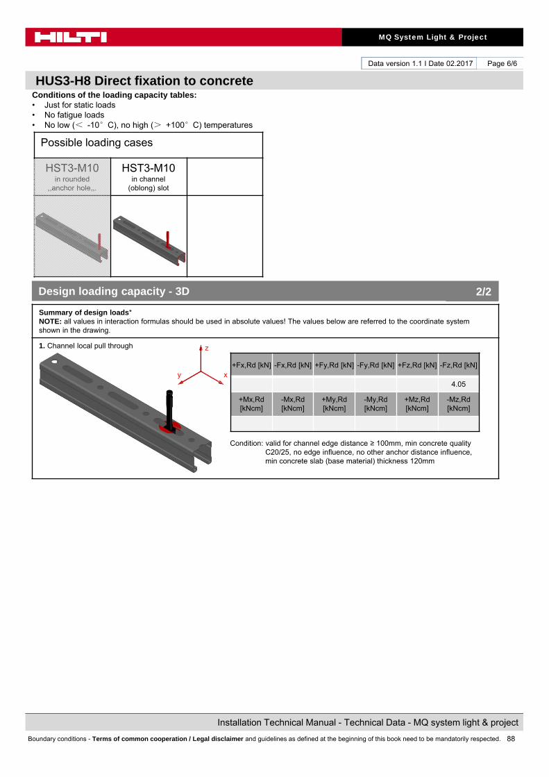
88
MQ System Light & Project
Installation Technical Manual - Technical Data - MQ system light & project
Boundary conditions - Terms of common cooperation / Legal disclaimer and guidelines as defined at the beginning of this book need to be mandatorily respected.
Data version 1.1 I Date 02.2017
HUS3-H8 Direct fixation to concrete
Page 6/6
Conditions of the loading capacity tables:• Just for static loads• No fatigue loads• No low (< -10°C), no high (> +100°C) temperatures
Summary of design loads*NOTE: all values in interaction formulas should be used in absolute values! The values below are referred to the coordinate system shown in the drawing.
1. Channel local pull through
Condition: valid for channel edge distance ≥ 100mm, min concrete quality C20/25, no edge influence, no other anchor distance influence,min concrete slab (base material) thickness 120mm
+Fx,Rd [kN] -Fx,Rd [kN] +Fy,Rd [kN] -Fy,Rd [kN] +Fz,Rd [kN] -Fz,Rd [kN]
4.05
+Mx,Rd[kNcm]
-Mx,Rd[kNcm]
+My,Rd[kNcm]
-My,Rd[kNcm]
+Mz,Rd[kNcm]
-Mz,Rd[kNcm]
Design loading capacity - 3D 2/2
Possible loading cases
HST3-M10 in rounded
,,anchor hole,,.
HST3-M10 in channel
(oblong) slot
z
xy

89
MQ System Light & Project
Installation Technical Manual - Technical Data - MQ system light & project
Boundary conditions - Terms of common cooperation / Legal disclaimer and guidelines as defined at the beginning of this book need to be mandatorily respected.

90
MQ System Light & Project
Installation Technical Manual - Technical Data - MQ system light & project
Boundary conditions - Terms of common cooperation / Legal disclaimer and guidelines as defined at the beginning of this book need to be mandatorily respected.
Data version 1.1 I Date 02.2017
Hilti. Outperform. Outlast.Hilti Corporation I 9494 Schaan I Liechtenstein I P +423-234 2111 I www.facebook.com/hiltigroup I www. Hilti.com
Hilt
i = r
egis
tere
d tr
adem
ark
of H
ilti C
orp.
, Sch
aan
I Iss
ued
by B
U I
nsta
llatio
n S
yste
ms
Ver
sion
1.1
I 02
.201
7 I ©
201
7 I R
ight
of t
echn
ical
and
pro
gram
me
chan
ges
rese
rved
S.
E.
& O
.