mpfi installatn
TRANSCRIPT
8/4/2019 mpfi installatn
http://slidepdf.com/reader/full/mpfi-installatn 1/16
©2001 Edelbrock Corporation
Brochure # 63-0043
Rev. 11Page 1 of 16
STOP!BEFORE BEGINNING INSTALLATION,
READ THESE IMPORTANT NOTES…
❑ For all vehicles except 1995 Tahoe, you MUST purchase a separate Edelbrock Fu
Pump Kit for this installation; single fuel tank vehicles use Edelbrock #3581, dual-tan
vehicles use #3580.
❑ External EGR is required for this installation. You must purchase External EG
Adapter kit #2899 for use with tubular exhaust headers, or use the left side exhausmanifold from a Vortec truck. GM #10220275 (EGR supply tube) also required (se
step #29 for more details).
❑ CHECK the Kit Contents and Suggested Tools lists on page 2 to be sure that you hav
all items necessary to finish installation.
❑ Make sure this kit is for your vehicle.
❑ This kit is designed work with Vortec cylinder heads and Vortec camshaft o
Edelbrock E-tec heads and Vortec camshaft developed for this application. Stoccompression must be maintained plus or minus two tenths of a ratio.
❑ You MUST change your computer chip for this kit to function on your vehicle and b
emissions legal. Complete the Chip Information Card and return to Edelbrock. W
will send the computer chip within the continental U.S., free of charge via UPS secon
day air. Orders outside of the continental U.S. will be shipped via the best method
the same costs as continental UPS second day air. If requested, customers may pa
for expedited shipping by providing a current Visa or Master Card.
❑ Your vehicle’s wiring harness and electronics must be in good shape or you may noget maximum performance and/or may experience problems. The TBI will work wit
less adequate connections, but the Performer Multi-Point EFI System is much mor
sensitive than a stock TBI.
❑ Read ALL instructions before beginning installation.
❑ Note that fuel tank or bed of pick-up MUST be removed.
PERFORMER MULTI-POINT EFI SYSTE
for Vortec Engine GM #12530
Catalog #3505 and #350
INSTALLATION INSTRUCTION
8/4/2019 mpfi installatn
http://slidepdf.com/reader/full/mpfi-installatn 2/16
©2001 Edelbrock Corporation
Brochure # 63-0043
Rev. 11Page 2 of 16
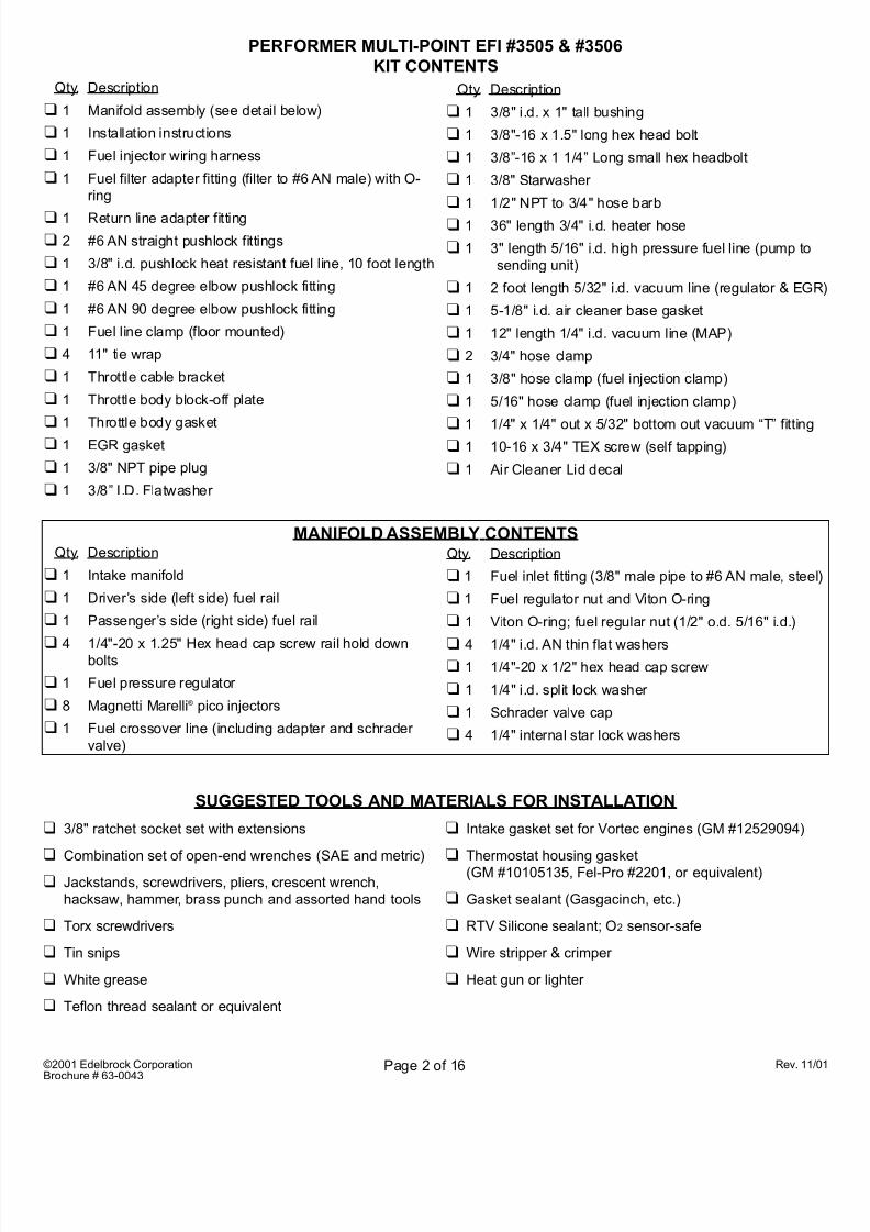
Qty. Description
❑ 1 Intake manifold
❑ 1 Driver’s side (left side) fuel rail
❑ 1 Passenger’s side (right side) fuel rail
❑ 4 1/4"-20 x 1.25" Hex head cap screw rail hold downbolts
❑ 1 Fuel pressure regulator
❑ 8 Magnetti Marelli® pico injectors
❑ 1 Fuel crossover line (including adapter and schrader
valve)
Qty. Description
❑ 1 Manifold assembly (see detail below)
❑ 1 Installation instructions
❑ 1 Fuel injector wiring harness
❑ 1 Fuel filter adapter fitting (filter to #6 AN male) with O-
ring
❑ 1 Return line adapter fitting
❑ 2 #6 AN straight pushlock fittings
❑ 1 3/8" i.d. pushlock heat resistant fuel line, 10 foot length
❑ 1 #6 AN 45 degree elbow pushlock fitting
❑ 1 #6 AN 90 degree elbow pushlock fitting
❑ 1 Fuel line clamp (floor mounted)
❑ 4 11" tie wrap
❑ 1 Throttle cable bracket
❑ 1 Throttle body block-off plate
❑ 1 Throttle body gasket
❑ 1 EGR gasket
❑ 1 3/8" NPT pipe plug
❑ 1 3/8” I.D. Flatwasher
Qty. Description
❑ 1 3/8" i.d. x 1" tall bushing
❑ 1 3/8"-16 x 1.5" long hex head bolt
❑ 1 3/8”-16 x 1 1/4” Long small hex headbolt
❑ 1 3/8" Starwasher
❑ 1 1/2" NPT to 3/4" hose barb
❑ 1 36" length 3/4" i.d. heater hose
❑ 1 3" length 5/16" i.d. high pressure fuel line (pump to
sending unit)
❑ 1 2 foot length 5/32" i.d. vacuum line (regulator & EG
❑ 1 5-1/8" i.d. air cleaner base gasket
❑ 1 12" length 1/4" i.d. vacuum line (MAP)
❑ 2 3/4" hose clamp
❑ 1 3/8" hose clamp (fuel injection clamp)
❑ 1 5/16" hose clamp (fuel injection clamp)
❑1 1/4" x 1/4" out x 5/32" bottom out vacuum “T” fitting
❑ 1 10-16 x 3/4" TEX screw (self tapping)
❑ 1 Air Cleaner Lid decal
Qty. Description
❑ 1 Fuel inlet fitting (3/8" male pipe to #6 AN male, stee
❑ 1 Fuel regulator nut and Viton O-ring
❑ 1 Viton O-ring; fuel regular nut (1/2" o.d. 5/16" i.d.)
❑ 4 1/4" i.d. AN thin flat washers❑ 1 1/4"-20 x 1/2" hex head cap screw
❑ 1 1/4" i.d. split lock washer
❑ 1 Schrader valve cap
❑ 4 1/4" internal star lock washers
MANIFOLD ASSEMBLY CONTENTS
PERFORMER MULTI-POINT EFI #3505 & #3506
KIT CONTENTS
SUGGESTED TOOLS AND MATERIALS FOR INSTALLATION
❑ 3/8" ratchet socket set with extensions
❑ Combination set of open-end wrenches (SAE and metric)
❑ Jackstands, screwdrivers, pliers, crescent wrench,
hacksaw, hammer, brass punch and assorted hand tools
❑ Torx screwdrivers
❑ Tin snips
❑ White grease
❑ Teflon thread sealant or equivalent
❑ Intake gasket set for Vortec engines (GM #12529094)
❑ Thermostat housing gasket
(GM #10105135, Fel-Pro #2201, or equivalent)
❑ Gasket sealant (Gasgacinch, etc.)
❑ RTV Silicone sealant; O2 sensor-safe
❑ Wire stripper & crimper
❑ Heat gun or lighter
8/4/2019 mpfi installatn
http://slidepdf.com/reader/full/mpfi-installatn 3/16
©2001 Edelbrock Corporation
Brochure # 63-0043
Rev. 11Page 3 of 16
IMPORTANT INSTRUCTION
for ordering your FREE Edelbrock computer chip…You must use an Edelbrock chip with the Performe
Multi-Point EFI conversio
You must change the computer chip in your stock computer (ECU) for proper functioning and maximum
performance with the Edelbrock Performer Multi-Point EFI for 5.7L Chevy/GMC engines.
To receive your computer chip, please complete the attached postage-paid card and send to Edelbroc After receiving your card, Edelbrock will send the computer chip within the continental U.S., free
charge via UPS second day air. Orders outside of the continental U.S. will be shipped via the be
method at the same costs as continental UPS second day air. If requested, customers may pay fo
expedited shipping by providing a current Visa or Master Card.
When filling out your information card, please print clearly.
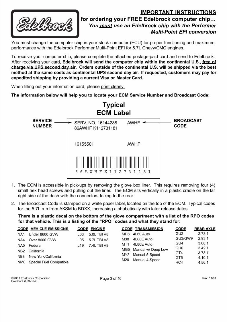
The information below will help you to locate your ECM Service Number and Broadcast Code:
SERVICE
NUMBER
BROADCAST
CODE
Typical
ECM LabelSERV. NO. 16144288 AWHF
86AWHF K112731181
16155501 AWHF
8 6 A W H F K 1 1 2 7 3 1 1 8 1
1. The ECM is accessible in pick-ups by removing the glove box liner. This requires removing four (
small hex head screws and pulling out the liner. The ECM sits vertically in a plastic cradle on the f
right side of the dash with the connectors facing to the rear.
2. The Broadcast Code is stamped on a white paper label, located on the top of the ECM. Typical code
for the 5.7L run from AKSM to BDXX, increasing alphabetically with later release dates.
CODE VEHICLE EMISSIONS
NA1 Under 8600 GVW
NA4 Over 8600 GVW
NA5 Federal
NB2 California
NB8 New York/California
NM8 Special Fuel Compatible
CODE TRANSMISSION
MD8 4L60 Auto
M30 4L68E Auto
MT1 4L80E Auto
MG5 Manual w/ Deep Low
MY2 Manual 5-Speed
M20 Manual 4-Speed
CODE ENGINE
L03 5.0L TBI V8
L05 5.7L TBI V8
L19 7.4L TBI V8
CODE REAR AXL
GU2 2.73:1
GU3/GW9 2.93:1
GU4 3.08:1
GU6 3.42:1
GT4 3.73:1
GT5 4.10:1
HC4 4.56:1
There is a plastic decal on the bottom of the glove compartment with a list of the RPO codes
for that vehicle. This is a listing of the “RPO” codes and what they stand for:
8/4/2019 mpfi installatn
http://slidepdf.com/reader/full/mpfi-installatn 4/16
©2001 Edelbrock Corporation
Brochure # 63-0043
Rev. 11Page 4 of 16
INSTALLATION INSTRUCTIONSfor Performer Multi-Point EFI System
for 5.7L (L31-Vortec) Replacment Engine GM #12530282Catalog #3505 for 1993-1995 Model Years
Catalog #3506 for 1987-1992 Model Years
• APPLICATION INFORMATION: Calibrated for the GM Vortec factory replacement engine, these mul
point fuel injection systems deliver outstanding performance in 1987-95 trucks originally equipped wit
Throttle Body Injection. Now you can buy a GM #12530282 long block from GM, install it in a truck wit
an Edelbrock EFI system, and enjoy modern performance without buying a new truck. These comple
systems utilize the stock computer and throttle body unit for a simple and effective conversion to mul
point fuel injection. Fuel is injected directly into each port in the head for ideal fuel distribution an
efficiency.
• TECHNICAL SUMMARY: In 1987, Chevrolet introduced their Throttle Body Injection (TBI) system
Produced from 1987 to 1995 on all pick-up trucks and Suburbans, this TBI system was essentially a
intermediate step between a carburetor and true port (multi-point) fuel injection. In these TBI system
two injectors are positioned above the throttle blades of a two-barrel throttle body and fuel is injecte
into the manifold, much like a carburetted system. This arrangement suffers from distribution problem
because the fuel spray from the injectors does not stay in suspension with the incoming air, resultin
in uneven distribution. Our Performer Multi-Point Systems include an intake manifold designed
deliver an equal charge to each cylinder. Each injector delivers exactly the same amount of fuel
each cylinder for an extremely even air/fuel ratio from cylinder-to-cylinder. This permits us to tune thsystem for ideal fuel and spark delivery for more horsepower, torque and improved mileage.
Performer Multi-Point Systems include all parts needed to make the conversion. The stock TBI unit
retained as an air valve and the factory computer (re-programmed) is also retained to control th
injectors in a batch-fire mode. In the Edelbrock systems, all of the factory sensors are retained an
fully functional. The compact size was achieved by using extruded aluminum fuel rails with ne
Magnetti Marelli® pico injectors. These are half the size of conventional style injectors.
• SPECIAL NOTICE: This Edelbrock part has received an Executive Order number (E.O. #) from th
California Air Resources Board (C.A.R.B.) making it legal for street use on pollution-controlled moto
vehicles in all 50 states. To assist you with emissions inspection, we have included a silver fan shrou
decal to verify that this part is a legal replacement part on the vehicle for which it is cataloged. Th
adhesive-backed decal should be affixed to your fan shroud next to the existing emission and engin
specification decal. Do not cover your original equipment specification decal with the Edelbrock fa
shroud decal. E.O.# decal is shipped with the computer chip .
If you have any questions or problems, call our
EFI Technical Hotline at: (800) 739-3737, Ext. 2819
8:00 am - 5:00 pm, Monday-Friday, Pacific Standard Time
8/4/2019 mpfi installatn
http://slidepdf.com/reader/full/mpfi-installatn 5/16
©2001 Edelbrock Corporation
Brochure # 63-0043
Rev. 11Page 5 of 16
1. Disconnect negative battery cable.
2. Drain coolant.
3. Remove air cleaner assembly.
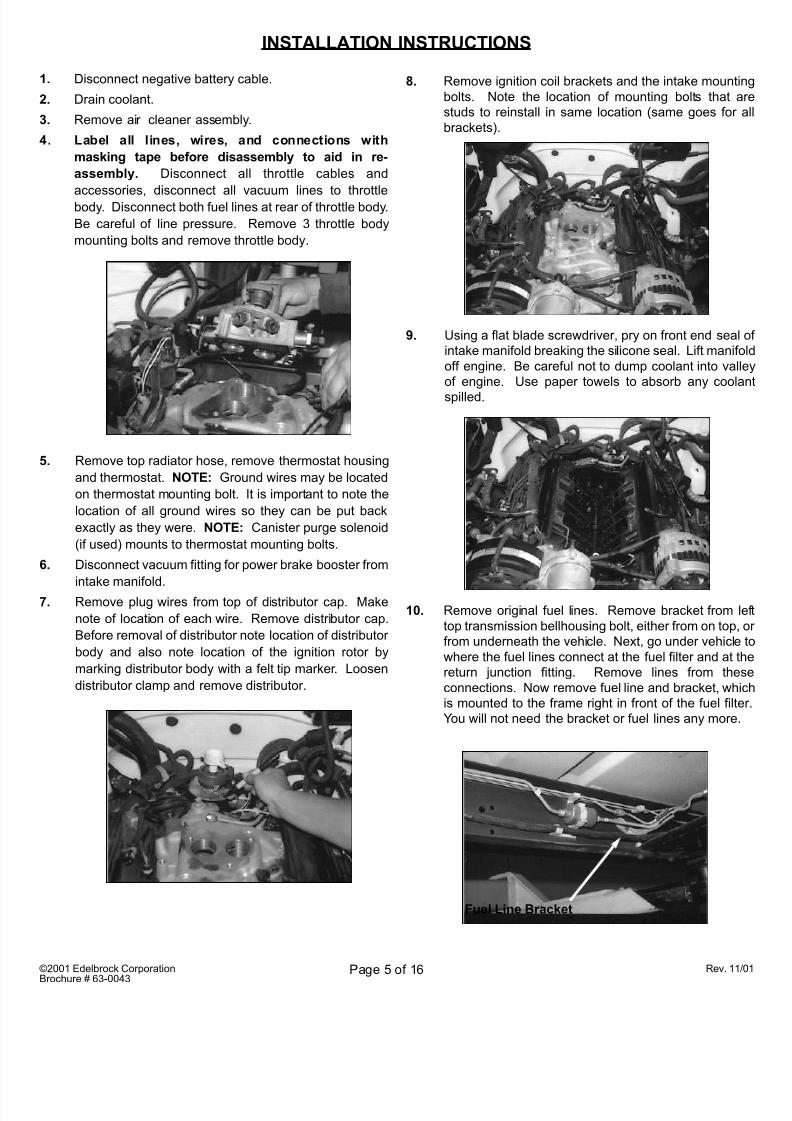
4. Label all lines, wires, and connections with
masking tape before disassembly to aid in re-
assembly. Disconnect all throttle cables and
accessories, disconnect all vacuum lines to throttlebody. Disconnect both fuel lines at rear of throttle body.
Be careful of line pressure. Remove 3 throttle body
mounting bolts and remove throttle body.
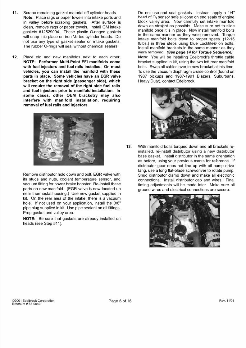
8. Remove ignition coil brackets and the intake mounti
bolts. Note the location of mounting bolts that a
studs to reinstall in same location (same goes for
brackets).
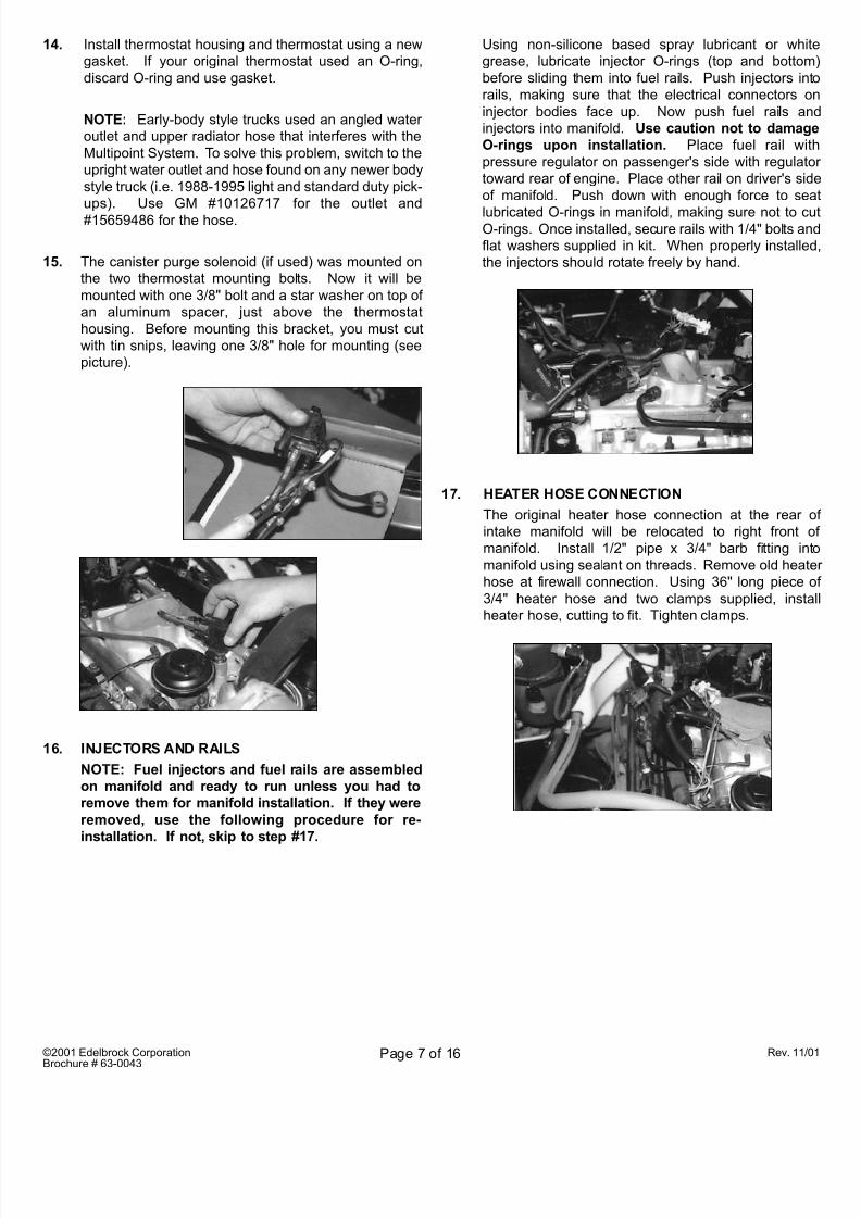
9. Using a flat blade screwdriver, pry on front end seal
intake manifold breaking the silicone seal. Lift manifo
off engine. Be careful not to dump coolant into vall
of engine. Use paper towels to absorb any coola
spilled.
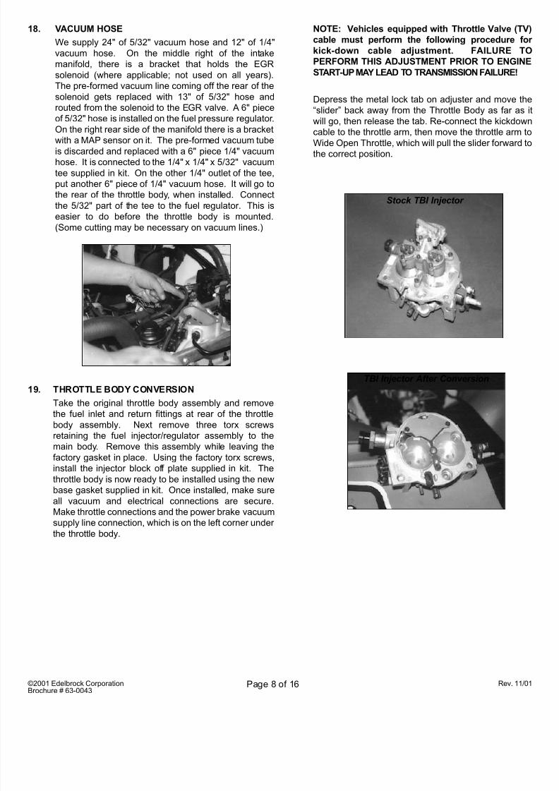
10. Remove original fuel lines. Remove bracket from l
top transmission bellhousing bolt, either from on top,
from underneath the vehicle. Next, go under vehicle
where the fuel lines connect at the fuel filter and at t
return junction fitting. Remove lines from the
connections. Now remove fuel line and bracket, whi
is mounted to the frame right in front of the fuel filte
You will not need the bracket or fuel lines any more.
INSTALLATION INSTRUCTIONS
Fuel Line Bracket
5. Remove top radiator hose, remove thermostat housing
and thermostat. NOTE: Ground wires may be located
on thermostat mounting bolt. It is important to note the
location of all ground wires so they can be put back
exactly as they were. NOTE: Canister purge solenoid
(if used) mounts to thermostat mounting bolts.
6. Disconnect vacuum fitting for power brake booster from
intake manifold.
7. Remove plug wires from top of distributor cap. Make
note of location of each wire. Remove distributor cap.
Before removal of distributor note location of distributor
body and also note location of the ignition rotor by
marking distributor body with a felt tip marker. Loosen
distributor clamp and remove distributor.
8/4/2019 mpfi installatn
http://slidepdf.com/reader/full/mpfi-installatn 6/16
©2001 Edelbrock Corporation
Brochure # 63-0043
Rev. 11Page 6 of 16
11. Scrape remaining gasket material off cylinder heads.
Note: Place rags or paper towels into intake ports and
in valley before scraping gaskets. After surface is
clean, remove rags or paper towels. Install GM intake
gaskets #12529094. These plastic O-ringed gaskets
will snap into place on iron Vortec cylinder heads. Do
not use any type of gasket sealer on intake gaskets.
The rubber O-rings will seal without chemical sealers.
12. Place old and new manifolds next to each other.
NOTE: Performer Multi-Point EFI manifolds comewith fuel injectors and fuel rails installed. On most
vehicles, you can install the manifold with these
parts in place. Some vehicles have an EGR valve
bracket on the right side (passenger side), which
will require the removal of the right side fuel rails
and fuel injectors prior to manifold installation. In
some cases, other OEM bracketry may also
interfere with manifold installation, requiring
removal of fuel rails and injectors.
13. With manifold bolts torqued down and all brackets r
installed, re-install distributor using a new distribut
base gasket. Install distributor in the same orientati
as before, using your previous marks for reference.
distributor gear does not line up with oil pump driv
tang, use a long flat-blade screwdriver to rotate pum
Snug distributor clamp down and make all electron
connections. Install distributor cap and wires. Fin
timing adjustments will be made later. Make sure
ground wires and electrical connections are secure.
Do not use end seal gaskets. Instead, apply a 1/bead of O2 sensor safe silicone on end seals of engiblock valley area. Now carefully set intake manifodown as straight as possible. Make sure not to slimanifold once it is in place. Now install manifold boin the same manner as they were removed. Torqintake manifold bolts down to proper specs. (12-ft/lbs.) in three steps using blue Locktite® on bolInstall manifold brackets in the same manner as thwere removed. (See page 14 for Torque Sequence
Note: You will be installing Edelbrock's throttle cab
bracket supplied in kit, using the two left rear manifobolts. Swap all cables over to new bracket at this tim
To use the vacuum diaphragm cruise control (found o
1987 pickups and 1987-1991 Blazers, Suburban
Heavy Duty), contact Edelbrock.
Remove distributor hold down and bolt, EGR valve with
its studs and nuts, coolant temperature sensor, and
vacuum fitting for power brake booster. Re-install theseparts on new manifold. (EGR valve is now located up
near thermostat housing.) Use new gasket supplied in
kit. On the rear area of the intake, there is a vacuum
hole. If not used on your application, install the 3/8"
pipe plug supplied in kit. Use pipe sealant on all fittings.
Prep gasket and valley area.
NOTE: Be sure that gaskets are already installed on
heads (see Step #11).
8/4/2019 mpfi installatn
http://slidepdf.com/reader/full/mpfi-installatn 7/16
©2001 Edelbrock Corporation
Brochure # 63-0043
Rev. 11Page 7 of 16
14. Install thermostat housing and thermostat using a new
gasket. If your original thermostat used an O-ring,
discard O-ring and use gasket.
NOTE: Early-body style trucks used an angled water
outlet and upper radiator hose that interferes with the
Multipoint System. To solve this problem, switch to the
upright water outlet and hose found on any newer body
style truck (i.e. 1988-1995 light and standard duty pick-
ups). Use GM #10126717 for the outlet and
#15659486 for the hose.
15. The canister purge solenoid (if used) was mounted on
the two thermostat mounting bolts. Now it will be
mounted with one 3/8" bolt and a star washer on top of
an aluminum spacer, just above the thermostat
housing. Before mounting this bracket, you must cut
with tin snips, leaving one 3/8" hole for mounting (see
picture).
16. INJECTORS AND RAILS
NOTE: Fuel injectors and fuel rails are assembled
on manifold and ready to run unless you had to
remove them for manifold installation. If they were
removed, use the following procedure for re-
installation. If not, skip to step #17.
Using non-silicone based spray lubricant or wh
grease, lubricate injector O-rings (top and bottom
before sliding them into fuel rails. Push injectors in
rails, making sure that the electrical connectors
injector bodies face up. Now push fuel rails a
injectors into manifold. Use caution not to dama
O-rings upon installation. Place fuel rail w
pressure regulator on passenger's side with regulat
toward rear of engine. Place other rail on driver's si
of manifold. Push down with enough force to se
lubricated O-rings in manifold, making sure not to cO-rings. Once installed, secure rails with 1/4" bolts a
flat washers supplied in kit. When properly installe
the injectors should rotate freely by hand.
17. HEATER HOSE CONNECTION
The original heater hose connection at the rear
intake manifold will be relocated to right front
manifold. Install 1/2" pipe x 3/4" barb fitting in
manifold using sealant on threads. Remove old hea
hose at firewall connection. Using 36" long piece
3/4" heater hose and two clamps supplied, inst
heater hose, cutting to fit. Tighten clamps.
8/4/2019 mpfi installatn
http://slidepdf.com/reader/full/mpfi-installatn 8/16
©2001 Edelbrock Corporation
Brochure # 63-0043
Rev. 11Page 8 of 16
18. VACUUM HOSE
We supply 24" of 5/32" vacuum hose and 12" of 1/4"
vacuum hose. On the middle right of the intake
manifold, there is a bracket that holds the EGR
solenoid (where applicable; not used on all years).
The pre-formed vacuum line coming off the rear of the
solenoid gets replaced with 13" of 5/32" hose and
routed from the solenoid to the EGR valve. A 6" piece
of 5/32" hose is installed on the fuel pressure regulator.
On the right rear side of the manifold there is a bracket
with a MAP sensor on it. The pre-formed vacuum tubeis discarded and replaced with a 6" piece 1/4" vacuum
hose. It is connected to the 1/4" x 1/4" x 5/32" vacuum
tee supplied in kit. On the other 1/4" outlet of the tee,
put another 6" piece of 1/4" vacuum hose. It will go to
the rear of the throttle body, when installed. Connect
the 5/32" part of the tee to the fuel regulator. This is
easier to do before the throttle body is mounted.
(Some cutting may be necessary on vacuum lines.)
19. THROTTLE BODY CONVERSION
Take the original throttle body assembly and remove
the fuel inlet and return fittings at rear of the throttlebody assembly. Next remove three torx screws
retaining the fuel injector/regulator assembly to the
main body. Remove this assembly while leaving the
factory gasket in place. Using the factory torx screws,
install the injector block off plate supplied in kit. The
throttle body is now ready to be installed using the new
base gasket supplied in kit. Once installed, make sure
all vacuum and electrical connections are secure.
Make throttle connections and the power brake vacuum
supply line connection, which is on the left corner under
the throttle body.
NOTE: Vehicles equipped with Throttle Valve (T
cable must perform the following procedure f
kick-down cable adjustment. FAILURE T
PERFORM THIS ADJUSTMENT PRIOR TO ENGIN
START-UPMAY LEAD TO TRANSMISSION FAILURE!
Depress the metal lock tab on adjuster and move th
“slider” back away from the Throttle Body as far as
will go, then release the tab. Re-connect the kickdow
cable to the throttle arm, then move the throttle arm
Wide Open Throttle, which will pull the slider forward
the correct position.
Stock TBI Injector
TBI Injector After Conversion
8/4/2019 mpfi installatn
http://slidepdf.com/reader/full/mpfi-installatn 9/16
©2001 Edelbrock Corporation
Brochure # 63-0043
Rev. 11Page 9 of 16
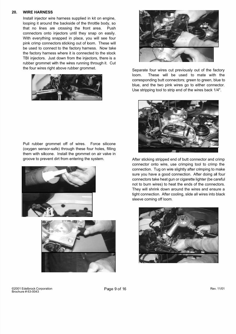
20. WIRE HARNESS
Install injector wire harness supplied in kit on engine,
looping it around the backside of the throttle body, so
that no lines are crossing the front area. Push
connectors onto injectors until they snap on easily.
With everything snapped in place, you will see four
pink crimp connectors sticking out of loom. These will
be used to connect to the factory harness. Now take
the factory harness where it is connected to the stock
TBI injectors. Just down from the injectors, there is arubber grommet with the wires running through it. Cut
the four wires right above rubber grommet.
Pull rubber grommet off of wires. Force silicone
(oxygen sensor-safe) through these four holes, filling
them with silicone. Install the grommet on air valve in
groove to prevent dirt from entering the system.
Separate four wires cut previously out of the facto
loom. These will be used to mate with t
corresponding butt connectors; green to green, blue
blue, and the two pink wires go to either connecto
Use stripping tool to strip end of the wires back 1/4"
After sticking stripped end of butt connector and crim
connector onto wire, use crimping tool to crimp th
connection. Tug on wire slightly after crimping to ma
sure you have a good connection. After doing all foconnectors take heat gun or cigarette lighter (be care
not to burn wires) to heat the ends of the connecto
They will shrink down around the wires and ensure
tight connection. After cooling, slide all wires into bla
sleeve coming off loom.
8/4/2019 mpfi installatn
http://slidepdf.com/reader/full/mpfi-installatn 10/16
©2001 Edelbrock Corporation
Brochure # 63-0043
Rev. 11Page 10 of 16
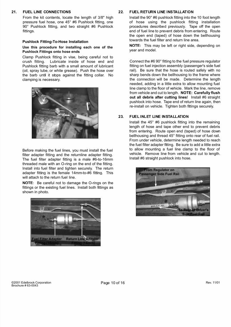
21. FUEL LINE CONNECTIONS
From the kit contents, locate the length of 3/8" high
pressure fuel hose, one 45° #6 Pushlock fitting, one
90° Pushlock fitting, and two straight #6 Pushlock
fittings.
Pushlock Fitting-To-Hose Installation
Use this procedure for installing each one of the
Pushlock Fittings onto hose ends
Clamp Pushlock fitting in vise, being careful not tocrush fitting. Lubricate inside of hose end and
Pushlock fitting barb with a small amount of lubricant
(oil, spray lube, or white grease). Push the hose over
the barb until it stops against the fitting collar. No
clamping is necessary.
Before making the fuel lines, you must install the fuel
filter adapter fitting and the returnline adapter fitting.
The fuel filter adapter fitting is a male #6-to-16mm
threaded male with an O-ring on the end of the fitting.
Install into fuel filter and tighten securely. The return
adapter fitting is the female 14mm-to-#6 fitting. Thiswill attach to the return fuel line.
NOTE: Be careful not to damage the O-rings on the
fittings or the existing fuel lines. Install both fittings as
shown in photo.
22. FUEL RETURN LINE INSTALLATION
Install the 90° #6 pushlock fitting into the 10 foot leng
of hose using the pushlock fitting installatio
procedures described previously. Tape off the op
end of fuel line to prevent debris from entering. Rou
the open end (taped) of hose down the bellhousin
towards the fuel filter and return line area.
NOTE: This may be left or right side, depending
year and model.
Connect the #6 90° fitting to the fuel pressure regulat
fitting on fuel injection assembly (passenger's side fu
rail). Be sure that the hose is routed safely with
sharp bends down the bellhousing to the frame whe
the connection will be made. Determine the leng
needed, adding in a little extra to allow mounting fu
line clamp to the floor of vehicle. Mark the line, remo
from vehicle and cut to length. NOTE: Carefully flu
out all debris after cutting lines! Install #6 straig
pushlock into hose. Tape end of return line again, th
re-install on vehicle. Tighten both fittings securely.
Return Line Adapter
Fitting (14mm)
Fuel Filter Adapter
Fitting (16mm)
23. FUEL INLET LINE INSTALLATION
Install the 45° #6 pushlock fitting into the remainin
length of hose and tape other end to prevent debr
from entering. Route open end (taped) of hose dow
bellhousing and thread 45° fitting onto rear of fuel ra
From under vehicle, determine length needed to rea
the fuel filter adapter fitting. Be sure to add a little ex
to allow mounting a fuel line clamp to the floor
vehicle. Remove line from vehicle and cut to leng
Install #6 straight pushlock into hose.
From Regulator on
Passenger Side Fuel Rail
To Rear of Driver’s
Side Fuel Rail
8/4/2019 mpfi installatn
http://slidepdf.com/reader/full/mpfi-installatn 11/16
©2001 Edelbrock Corporation
Brochure # 63-0043
Rev. 11Page 11 of 16
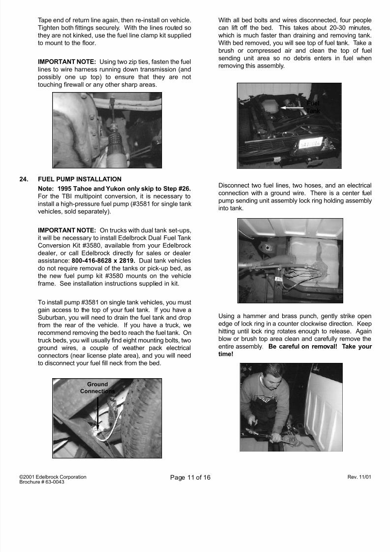
24. FUEL PUMP INSTALLATION
Note: 1995 Tahoe and Yukon only skip to Step #26.
For the TBI multipoint conversion, it is necessary to
install a high-pressure fuel pump (#3581 for single tank
vehicles, sold separately).
IMPORTANT NOTE: On trucks with dual tank set-ups,
it will be necessary to install Edelbrock Dual Fuel Tank
Conversion Kit #3580, available from your Edelbrock
dealer, or call Edelbrock directly for sales or dealer
assistance: 800-416-8628 x 2819. Dual tank vehicles
do not require removal of the tanks or pick-up bed, as
the new fuel pump kit #3580 mounts on the vehicle
frame. See installation instructions supplied in kit.
To install pump #3581 on single tank vehicles, you must
gain access to the top of your fuel tank. If you have a
Suburban, you will need to drain the fuel tank and drop
from the rear of the vehicle. If you have a truck, we
recommend removing the bed to reach the fuel tank. On
truck beds, you will usually find eight mounting bolts, two
ground wires, a couple of weather pack electrical
connectors (near license plate area), and you will need
to disconnect your fuel fill neck from the bed.
GroundConnections
Tape end of return line again, then re-install on vehicle.
Tighten both fittings securely. With the lines routed so
they are not kinked, use the fuel line clamp kit supplied
to mount to the floor.
IMPORTANT NOTE: Using two zip ties, fasten the fuel
lines to wire harness running down transmission (and
possibly one up top) to ensure that they are not
touching firewall or any other sharp areas.
With all bed bolts and wires disconnected, four peop
can lift off the bed. This takes about 20-30 minute
which is much faster than draining and removing tan
With bed removed, you will see top of fuel tank. Take
brush or compressed air and clean the top of fu
sending unit area so no debris enters in fuel wh
removing this assembly.
Fuel
Tank
Disconnect two fuel lines, two hoses, and an electric
connection with a ground wire. There is a center fupump sending unit assembly lock ring holding assemb
into tank.
Using a hammer and brass punch, gently strike ope
edge of lock ring in a counter clockwise direction. Ke
hitting until lock ring rotates enough to release. Aga
blow or brush top area clean and carefully remove th
entire assembly. Be careful on removal! Take yo
time!
8/4/2019 mpfi installatn
http://slidepdf.com/reader/full/mpfi-installatn 12/16
©2001 Edelbrock Corporation
Brochure # 63-0043
Rev. 11Page 12 of 16
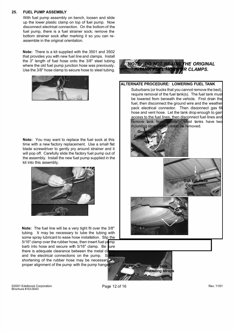
25. FUEL PUMP ASSEMBLY
With fuel pump assembly on bench, loosen and slide
up the lower plastic clamp on top of fuel pump. Now
disconnect electrical connection. On the bottom of the
fuel pump, there is a fuel strainer sock; remove the
bottom strainer sock after marking it so you can re-
assemble in the original orientation.
Note: There is a kit supplied with the 3501 and 3502
that provides you with new fuel line and clamps. Installthe 3" length of fuel hose onto the 3/8" steel tubing
where the old fuel pump junction hose was previously.
Use the 3/8" hose clamp to secure hose to steel tubing.
Note: You may want to replace the fuel sock at this
time with a new factory replacement. Use a small flat
blade screwdriver to gently pry around strainer and it
will pop off. Carefully slide the factory fuel pump out of
the assembly. Install the new fuel pump supplied in the
kit into this assembly.
NOTE: DO NOT RE-USE THE ORIGINALINTANK FUEL HOSE OR CLAMPS.
ALTERNATE PROCEDURE: LOWERING FUEL TANK
Suburbans (or trucks that you cannot remove the bed
require removal of the fuel tank(s). The fuel tank mu
be lowered from beneath the vehicle. First drain th
fuel, then disconnect the ground wire and the weath
pack electrical connector. Then disconnect gas f
hose and vent hose. Let the tank drop enough to ga
access to the fuel lines, then disconnect fuel lines anremove tank from vehicle. Most tanks have tw
mounting straps which must be removed.
Gas Fill Hose
Connection
Gas tank
mounting straps
Note: The fuel line will be a very tight fit over the 3/8"
tubing. It may be necessary to lube the tubing withsome spray lubricant to ease hose installation. Slip the
5/16" clamp over the rubber hose, then insert fuel pump
barb into hose and secure with 5/16" clamp. Be sure
there is adequate clearance between the metal clamp
and the electrical connections on the pump. Some
shortening of the rubber hose may be necessary for
proper alignment of the pump with the pump hanger.
Ground
Connection
8/4/2019 mpfi installatn
http://slidepdf.com/reader/full/mpfi-installatn 13/16
©2001 Edelbrock Corporation
Brochure # 63-0043
Rev. 11Page 13 of 16
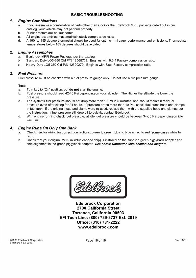
On the ECM, you will find the service number and th
broadcast code. Both are needed in order to make
new calibration chip for your particular vehicle. Th
should be done well before installation to allow enou
time for the new chip to arrive. Use the chip order ca
enclosed with these instructions.
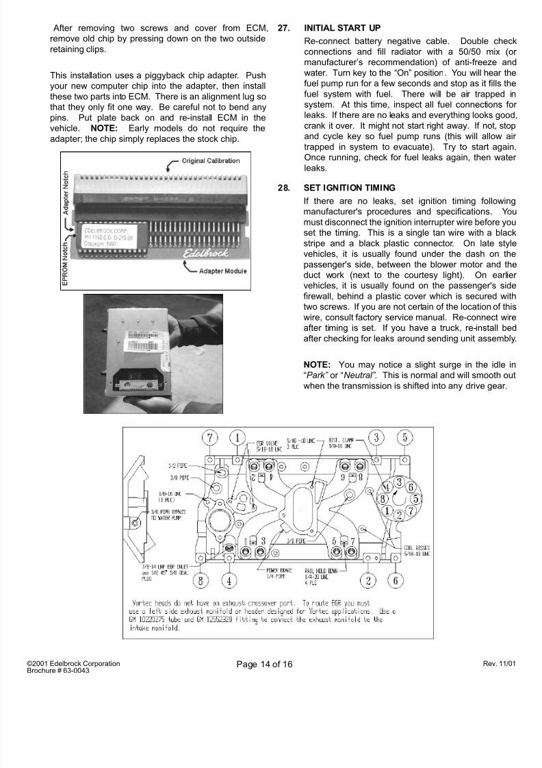
26. NEW COMPUTER CHIP INSTALLATION
IMPORTANT NOTE: COMPUTER CHIP MUST B
ORDERED BEFORE BEGINNING INSTALLATIO
Open glove box and remove four screws mounting t
inner tray. Remove glove box tray.
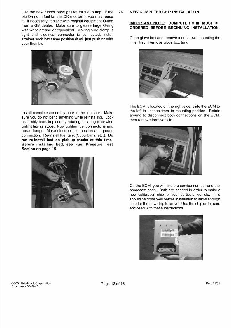
Use the new rubber base gasket for fuel pump. If the
big O-ring in fuel tank is OK (not torn), you may reuse
it. If necessary, replace with original equipment O-ring
from a GM dealer. Make sure to grease large O-ring
with white grease or equivalent. Making sure clamp is
tight and electrical connector is connected, install
strainer sock into same position (it will just push on with
your thumb).
Install complete assembly back in the fuel tank. Make
sure you do not bend anything while reinstalling. Lock
assembly back in place by rotating lock ring clockwise
until it hits its stops. Now tighten fuel connections and
hose clamps. Make electronic connection and ground
connection. Re-install fuel tank (Suburbans, etc.). Do
not re-install bed on pick-up trucks at this time.
Before installing bed, see Fuel Pressure Test
Section on page 15.
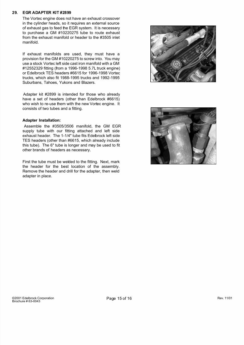
The ECM is located on the right side; slide the ECM
the left to unsnap from its mounting position. Rota
around to disconnect both connections on the ECthen remove from vehicle.
8/4/2019 mpfi installatn
http://slidepdf.com/reader/full/mpfi-installatn 14/16
8/4/2019 mpfi installatn
http://slidepdf.com/reader/full/mpfi-installatn 15/16
©2001 Edelbrock Corporation
Brochure # 63-0043
Rev. 11Page 15 of 16
29. EGR ADAPTER KIT #2899
The Vortec engine does not have an exhaust crossover
in the cylinder heads, so it requires an external source
of exhaust gas to feed the EGR system. It is necessary
to purchase a GM #10220275 tube to route exhaust
from the exhaust manifold or header to the #3505 inlet
manifold.
If exhaust manifolds are used, they must have a
provision for the GM #10220275 to screw into. You mayuse a stock Vortec left side cast iron manifold with a GM
#12552329 fitting (from a 1996-1998 5.7L truck engine)
or Edelbrock TES headers #6615 for 1996-1998 Vortec
trucks, which also fit 1988-1995 trucks and 1992-1995
Suburbans, Tahoes, Yukons and Blazers.
Adapter kit #2899 is intended for those who already
have a set of headers (other than Edelbrock #6615)
who wish to re-use them with the new Vortec engine. It
consists of two tubes and a fitting.
Adapter Installation: Assemble the #3505/3506 manifold, the GM EGR
supply tube with our fitting attached and left side
exhaust header. The 1-1/4" tube fits Edelbrock left side
TES headers (other than #6615, which already include
this tube). The 6" tube is longer and may be used to fit
other brands of headers as necessary.
First the tube must be welded to the fitting. Next, mark
the header for the best location of the assembly.
Remove the header and drill for the adapter, then weld
adapter in place.
8/4/2019 mpfi installatn
http://slidepdf.com/reader/full/mpfi-installatn 16/16
©2001 Edelbrock Corporation Rev. 11Page 16 of 16
Edelbrock Corporation2700 California Street
Torrance, California 90503EFI Tech Line: (800) 739-3737 Ext. 2819
Office: (310) 781-2222www.edelbrock.com
BASIC TROUBLESHOOTING
1. Engine Combinationsa. If you assemble a combination of parts other than stock or the Edelbrock MPFI package called out in our
catalog, your vehicle may not perform properly.
b. Stroker motors are not supported .
c. All engine assemblies must maintain stock compression ratios .
d. A 190- to 195-degree thermostat should be used for optimum mileage, performance and emissions. Thermosta
temperatures below 185 degrees should be avoided.
2. Engine Assembliesa. Edelbrock MPFI Power Package per the catalog.
b. Standard Duty LO5-350 Cid P/N 12568758. Engines with 9.3:1 Factory compression ratio.
c. Heavy Duty LO5-350 Cid P/N 12520270. Engines with 8.6:1 Factory compression ratio.
3. Fuel PressureFuel pressure must be checked with a fuel pressure gauge only. Do not use a tire pressure gauge.
Test:
a. Turn key to “On” position, but do not start the engine.
b. Fuel pressure should read 42-45 Psi depending on your altitude . The Higher the altitude the lower the
pressure.c. The systems fuel pressure should not drop more than 10 Psi in 5 minutes, and should maintain residual
pressure even after sitting for 24 hours. If pressure drops more than 10 Psi, check fuel pump hose and clamps
in fuel tank. If the original hose and clamp were re-used, replace them with the supplied hose and clamps per
the instruction. If fuel pressure still drop off to quickly, contact Edelbrock .
d. With engine running check fuel pressure, at idle fuel pressure should be between 34-38 Psi depending on idle
vacuum.
4. Engine Runs On Only One Bank a. Check injector wiring for correct connections, green to green, blue to blue or red to red (some cases white to
red).
b. Check that your original MemCal (blue capped chip) is installed on the supplied green piggyback adapter and
chip alignment in the green piggyback adapter. See above Computer Chip section and diagram.