mp bes plxxxx00 sr59xxx0 ds42xx00 v1.0 en -...
TRANSCRIPT

Touch pushbuttons and thermostats
Cubik series / TRMD-K
Programming manual

Cubik series / TRMD-K - Touch pushbuttons and thermostats Programming manual v1.0
www.besknx.com 2
Index
1 General description ...................................................................................................................................... 3
1.1 About this manual ............................................................................................................................................... 3
2 Technical description .................................................................................................................................. 4
3 Programming ................................................................................................................................................ 5
3.1 ETS application program information ................................................................................................................ 5
3.2 Assignment of individual address ..................................................................................................................... 6
3.3 Selection of the type of device ........................................................................................................................... 6
3.4 Communication objects associated with the LEDs .......................................................................................... 8 Communication objects table .............................................................................................................................................. 8
3.5 Inputs communication objects ........................................................................................................................... 8 Table of switch type inputs .................................................................................................................................................. 9 Table of pushbutton type inputs .......................................................................................................................................... 9
3.6 Humidity sensor objects ..................................................................................................................................... 9
3.7 Dew point communication objects ................................................................................................................... 10
3.8 Night mode communication objects ................................................................................................................ 10
3.9 Cleaning mode communication objects .......................................................................................................... 11
3.10 LEDs parameters ............................................................................................................................................... 11
3.11 Inputs parameters .............................................................................................................................................. 13 Parameters of switch type inputs .................................................................................................................................. 13 Parameters of pushbutton type inputs .......................................................................................................................... 15
3.12 Thermostat parameters ..................................................................................................................................... 16 Thermostat functions .................................................................................................................................................... 16
3.12.1.1 Temperature controller ............................................................................................................................................. 17 3.12.1.2 Heating / Cooling ..................................................................................................................................................... 20 3.12.1.3 Special modes ......................................................................................................................................................... 22
3.13 Parameters of humidity sensor ........................................................................................................................ 23
3.14 Parameters of dew point calculation ............................................................................................................... 24
3.15 Night mode ......................................................................................................................................................... 24
3.16 Cleaning mode ................................................................................................................................................... 25
3.17 Advanced functions .......................................................................................................................................... 26 Arithmetic and Logic block (ALU) ................................................................................................................................. 27 Timer / counter block .................................................................................................................................................... 28
4 Installation ...................................................................................................................................................32

Cubik series / TRMD-K - Touch pushbuttons and thermostats Programming manual v1.0
www.besknx.com 3
1 General description Cubik Bes series consist of capacitive pushbuttons with different number of touch areas, depending on the model, and thermostats. The pushbuttons also have LEDs in each of the touch areas and, in addition, they all include an internal thermostat and a humidity sensor. The thermostats could have an interface to represent the ambient temperature and / or the setpoint temperature. In addition, they all include logical arithmetic unit and timers.
All these devices have the possibility of personalization in three different modes: basic, only available in white or black glass with fixed glass; design, with customizable fixed glass; and capriccio, with customizable glass fixed to the back of magnetic form so that the glass can be replaced at the request of the client. The TRMD-K only has the first two possibilities of personalization.
1.1 About this manual
This manual describes how to program the Cubik de Bes series (except the Cubik-T thermostat, SR59X1X0, and the Cubik-VH, PL221X00) and the TRMD-K thermostat. That is why some of the sections in this manual do not apply to some device references, for example, those that describe the entries in the thermostats that lack them. In the following section, the technical characteristics of each reference are specified, a table in which you can check the differences between them.

Cubik series / TRMD-K - Touch pushbuttons and thermostats Programming manual v1.0
www.besknx.com 4
2 Technical description The technical characteristics of the different devices to which this manual applies are summarized below:
Cubi
k-SQ
2 PLX1
2X00
Cubi
k-SQ
4 PLX1
4X00
Cubi
k-SQ
6 PLX1
6X00
Cubi
k-V6
PLX2
6X00
Cubi
k-V8
PLX2
8X00
Cubi
k-TH
SR59X3
X0
Cubi
k-TL
SR
59X2
X0
TRM
D-K
DS42X
X00
Power supply 29 VDC KNX BUS
29 VDC KNX BUS
29 VDC KNX BUS
29 VDC KNX BUS
29 VDC KNX BUS
29 VDC KNX BUS 29 VDC KNX BUS 29 VDC KNX BUS
Consumption 10 mA
10 mA
10 mA
10 mA
10 mA 10 mA 15 mA 30 mA
BUS devices equivalence* 2 2 2 2 2 2 3 6
Mounting Universal mechanism box
Size 88 x 88 x 6 mm 129 x 88 x 6 mm 88 x 88 x 6 mm 129 x 88 x 6 mm 129 x 88 x 6 mm
Connections KNX BUS therminal connection Touch areas 2 4 6 6 8 8 8
Interface
Thermostat
Humidity sensor
Temperature range
Working: -10 ºC a 55 ºC Storage: -30 ºC a 60 ºC
Transport: -30 ºC a 60 ºC
Regulation In accordance with the electromagnetic compatibility and low voltage directives: EN 50090-2-2 / UNE-EN 61000-6-3:2007 / UNE-EN 61000-6-1:2007 / UNE-EN 61010-1
* 1 BUS device = 5 mA

Cubik series / TRMD-K - Touch pushbuttons and thermostats Programming manual v1.0
www.besknx.com 5
3 Programming
3.1 ETS application program information
Application program: Bes – Ingenium / Cubik
Application program version: 1.0
Maximum number of communcation program: 256.
Maximum number of assignments: 256.
ETS mínimum version: ETS5
The parameters of the device are configured through a parameter window.

Cubik series / TRMD-K - Touch pushbuttons and thermostats Programming manual v1.0
www.besknx.com 6
3.2 Assignment of individual address
The devices have a programming button located on the back of it to establish the KNX individual address.
A red LED next to the button lights up when the button is pressed manually or when the device is forced remotely to programming mode.
The LED turns off automatically if the ETS has assigned an individual address correctly or if the program button is pressed manually again.
Like any other device KNX single unique address for the correct operation of the device installation is required and is assigned by the ETS in the same way as any other equipment of this protocol.
3.3 Selection of the type of device
The parameters of the device are configured using a specific parameters dialog.
Existen diversas pestañas para configurar los distintos parámetros dependiendo del tipo de dispositivo seleccionado. El tipo de dispositivo que se desea programar se selecciona en el menú desplegable Tipo de dispositivo.

Cubik series / TRMD-K - Touch pushbuttons and thermostats Programming manual v1.0
www.besknx.com 7
After that, a number of tabs will appear on the left side, depending on the selected device. From them, the programming of the various parameters of the device is performed: configuration of the inputs, the LED behavior, configuration of the thermostat, etc.

Cubik series / TRMD-K - Touch pushbuttons and thermostats Programming manual v1.0
www.besknx.com 8
3.4 Communication objects associated with the LEDs
Communication objects table
The following table lists the communication objects for the first Cubik LEDs. All LEDs have the same communication objects and are displayed or hidden depending on the selected parameters.
Object Name - Function Size DPT Flags
C R W T U
0 LED 1 - Switch on/off 1 bit 1.001 ● ●
1 LED 1 - Switch on/off status 1 bit 1.001 ● ● ●
2 LED 1 – Lock/Unlock 1 bit 1.001 ● ●
3 LED 1 – Timer delay/staircase switch on/off 1 bit 1.001 ● ●
Name LED X - Switch on/off
Function 1 bit communication object to turn the X LED on and off
Description When a ‘1’ is received through this object, the output is activated. When a ‘0’ is received the output is deactivated, in the operation in ‘normally open’ mode. In ‘normally closed’ mode the operation would be the opposite.
The selection of the operating mode is made in the parameters tab of each LED.
Name LED X - Switch on/off status
Function 1 bit communication object for feedback about the status of LED X
Description Notify the LED status
Name LED X – Lock/Unlock
Function 1 bit communication object to lock the control of the state of the X LED
Description By this object, whose polarity is selected in the parameter destined for this purpose, the LED control is locked so that in this case, if it is acted on switch on/off object is, the action will not be reflected in the status of the LED.
Name LED X – Timer delay/staircase switch on/off
Function 1 bit communication object to turn the X LED on and off with delay or staircase timer
Description The status of the LED is modified by this object. While the switch object on/off does it instantaneously, with this object the orders are executed with the delays configured in the parameters, in the Timer section of each LED.
3.5 Inputs communication objects
The following tables list the communication objects available for the first of the pushbutton inputs, which can be extrapolated for the other inputs.

Cubik series / TRMD-K - Touch pushbuttons and thermostats Programming manual v1.0
www.besknx.com 9
Note: The writing flags of the entries can be activated if they are not in this way by default. This ensures that several inputs work synchronously and the switching action is carried out correctly.
Table of switch type inputs
Object Name - Function Length DPT Flags
C R W T U
164 Button 1 – Close (object 1) - Switch on/off 1 bit 1.001 ● ○ ●
165 Button 2 – Close (object 1) - Switch on/off 1 bit 1.001 ● ○ ●
Table of pushbutton type inputs
Object Name - Function Length DPT Flags
C R W T U
164 Button 1 - Short press - Switch on/off 1 bit 1.001 ● ○ ●
165 Button 1 - Long press - Switch on/off 1 bit 1.001 ● ○ ●
3.6 Humidity sensor objects
Once the humidity sensor option is activated, the following options will appear.
Number Name Object name Length C R W T U Type of data 125 Humidity Measured humidity status 2
bytes C R - T - humidity (%)
126 Humidity High alarm (1=Alarm / 0=No alarm) 1 bit C R - T - switch
127 Humidity Low alarm (1=Alarm / 0=No alarm) 1 bit C R - T - switch
Name Humidity – Measured humidity status
Function 2-byte communication object to read and/or notify (depending on the configuration of the parameters)
Description By this object the measure of relative humidity in % is known
Name Humidity – High alarm (1=Alarm / 0=No alarm)
Function 1 bit communication object to read and/or notify the upper limit humidity alarm

Cubik series / TRMD-K - Touch pushbuttons and thermostats Programming manual v1.0
www.besknx.com 10
Description By this object it is notified if the upper humidity limit established in the parameter for this purpose has been exceeded.
Name Humidity – Low alarm (1=Alarm / 0=No alarm)
Function 1 bit communication object to read and / or notify the humidity alarm of the lower limit
Description By this object it is notified if the relative humidity is lower than the lower humidity limit established in the parameter for that effect
3.7 Dew point communication objects
Number Name Object function Length C R W T U Type of data
129 Dew point Alarm 1 bit C R - T - switch 128 Dew point Temperature value 2 bytes C R - T - temperature (°C)
Name Dew point – Alarm
Function 1-bit communication object to notify a dew point alarm
Description By this 1-bit communication object, the sensor notifies if the dew point has dropped from a value defined in the corresponding parameter
Name Dew point – Temperature value
Function 1 bit communication object to notify the dew temperature
Description 2-byte communication object by which the sensor reports the calculated dew temperature according to the relative humidity and the measured ambient temperature.
3.8 Night mode communication objects
Number Name Object function Length C R W T U Type of data
253 Night mode Enable (1=Enable / 0=Disable) 1 bit C - W - - switch
Name Night mode – Enable (1=Enable / 0=Disable)
Function 1 bit communication object to enable or disable night mode
Description By means of this 1 bit communication object, the user can set the night mode so that the LEDs of the button acquire a percentage of brightness different from that of the usual operation

Cubik series / TRMD-K - Touch pushbuttons and thermostats Programming manual v1.0
www.besknx.com 11
3.9 Cleaning mode communication objects
Number Name Object function Length C R W T U Type of data
252 Cleaning mode Enable (1=Enable / 0=Disable) 1 bit C - W - - switch
Name Cleaning mode – Enable (1=Enable / 0=Disable)
Function 1 bit communication object to enable or disable the cleaning mode
Description By this communication object, the user can enable or disable the pushbutton cleaning mode so that the touch areas are disabled for a time set by a parameter, so that the button can be cleaned without unwanted pulses
3.10 LEDs parameters
In the parameters tab of the LEDs, once enabled, you can configure the ones explained below.
Working mode: It can be normally open or normally closed. In normally open mode the output is controlled following the standard logic: 1 = closed, 0 = open. In normally closed mode, it is controlled with the inverse logic: 1 = open, 0 = closed.
Brightness level: Parameter which allows to regulate the brightness of the LEDs. It allows to configure the light intensity of the LED outputs for its ON and OFF level, being the 100% value the maximum configurable brightness and a 0% value turns the light off.
Status after voltage recovery: status after feed recovery. Selection of the mode to which the output will be changed after recovering from a power loss. The available options are:

Cubik series / TRMD-K - Touch pushbuttons and thermostats Programming manual v1.0
www.besknx.com 12
- No change: the status of the LED will remain with the value it had before the voltage loss. - LED ON: the LED will turn on after the voltage is recovered. - LED OFF: the LED will turn off after the voltage is recovered.
Lock/unlock: enable / disable control of the status of the LED. If this option is activated, a new menu will appear on the left, just below the channel configuration menu, as shown in the image below. In this section you can choose the polarity and behavior of the LED after locking or unlocking it. The options available when blocking are: turn off, turn on the LED or not make changes. However, when you unlock the options are: turn off, turn on the LED, last value before locking or update. These options are explained below:
- Open output: Turn off the LED. - Close output: Turn on the corresponding LED. - Last value before locking: It remains in the state it was in before sending the block order for the communication object destined for that purpose. - Update: Once unlocked, the LED will change the status to the last value received during its locking.
Timer: This option allows the selection of delays or timings in the LED control. The delays can be configured for turn on and/or off, be instantaneous, configure staircase timers or both combined.
Note: lock communication object will not affect to this function

Cubik series / TRMD-K - Touch pushbuttons and thermostats Programming manual v1.0
www.besknx.com 13
The timers that can be selected are the following:
Instant on: With this option, the LED would turn on instantaneously when receiving a '1' by the communication object, while a delay could be chosen when the LED is turned off (when a '0' is received by the communication object) if Delay off is selected in the Switch off action parameter. It also allows the selection of the size of the communication object between 1 bit, 4 bits or both, allowing the timer to be executed from dimming communication objects.
Delay on: A delay time is counted, selectable in Delay time, before turning on the corresponding LED. This option also allows to have a delay in LED off (when a '0' is received by the communication object) if Delay off is selected in the Switch off action parameter. It also allows the selection of the size of the communication object between 1 bit, 4 bits or both, allowing the timer to be executed from dimming communication objects.
Staircase timer: When receiving a '1' the LED lights up and stays on for the time defined in Staircase time, turning off after that time. By means of the Retriggerable parameter, it is selected if the countdown, when receiving a new '1' by the communication object, will be reset or not. It is also selectable by the parameter Switch off action, the behavior of the device when a '0' is received by this communication object. It also allows the selection of the size of the communication object between 1 bit, 4 bits or both, allowing the timer to be executed from dimming communication objects.
Delay on + Staircase timer. The device counts down the time defined in Delay on before starting a staircase timer cycle. If the device receives a new '1' for the communication object, in case the device is counting the delay on time, it will count this time again; if the device is counting the staircase timing, the device will turn off the LED and start a new cycle with the countdown of the delay on time. It also allows the selection of the size of the communication object between 1 bit, 4 bits or both, allowing the timer to be executed from dimming communication objects.
3.11 Inputs parameters
Parameters of switch type inputs
When the working mode of a touch area is defined as a switch, you can configure the following parameters:

Cubik series / TRMD-K - Touch pushbuttons and thermostats Programming manual v1.0
www.besknx.com 14
Number of objects: between an object or two can be chosen. If 2 objects are selected, the following options can be chosen in both object 1 and object 2. A new communication object corresponding to the second object will also appear.
Button response: it can be chosen between open, closed or switch. If the raising/falling option is selected, a value must be chosen for the action when pressing and another one when releasing the touch area.
Action: It is the action that is wanted to be done. The options are on/off, send value or execute a scene. If the action is to execute a scene a new menu will appear to write the number of the scene to be executed and if it is in activated or learning mode .
Close value: You can choose to send a 0 or 1 value, or make a switch (switch).

Cubik series / TRMD-K - Touch pushbuttons and thermostats Programming manual v1.0
www.besknx.com 15
Parameters of pushbutton type inputs
When the working mode of a touch area is defined as a short/long press, the following parameters can be configured for each type of pulse:
No action: Nothing will be exectuted when pressed.
Switch on/off: You must choose the value of the output when acting on the input: open, closed or open / closed switch.
Send value: The output will send the value written in the box. The format of the introduced data can also be selected.
Dimming: The output will make a dimming as indicated: increasing (more luminosity), decreasing (less luminosity) or dimming alternately up and down. The will be carried out with an interval of regulation which will be established in the "step" box

Cubik series / TRMD-K - Touch pushbuttons and thermostats Programming manual v1.0
www.besknx.com 16
Shutter/Blind: The response of the blinds can be movement or stopping/steps of slats. And its direction: up, down or combined up/down.
Scene: Activate scenes or put them in learning mode. The number of the scene to be executed will be chosen, which will be between 1 and 64.
As stated above, all options are available for both short and long press. You must set the touch time for a long press.
3.12 Thermostat parameters
Thermostat functions
In the case of inhabiting the functions of the thermostat of the device in the General section, a new tab appears in the menu on the left:
Parameter Use external temperature sensor
Values Yes / No
Description
This parameter allows to choose if the controller reference is the internal temperature probe or the measured form another sensor connected to the KNX system. - No: The controller will use its internal measure. You can calibrate the measurement and set up
recurring or change notifications. The value can be read or notify via Measured temperature object - Yes: The temperature controller used as a reference value written to the Measured temperature
object and despises its internal measure. Parameter Sensor calibration
Values From -8ºC to +5ºC
Description
This parameter allows you to correct the measurement of the temperature sensor if necessary. The set value is added or subtracted to the current measurement sensor, which can be checked by Measured temperature object.

Cubik series / TRMD-K - Touch pushbuttons and thermostats Programming manual v1.0
www.besknx.com 17
Parameter Transmission of measured temperature
Values Only read, cyclically (time), on change (ºC) or both (ºC y time).
Description This parameter is used to configure the frequency with which to send notifications of temperature by measured temperature object
Parameter Period of time (seconds) Values From 5 to 80
Description If the transmission measured temperature parameter is set as cyclically or both, this additional parameter allows to define the period of sending notifications in seconds.
Parameter Minimum change Values From 0,2 to 3,2 ºC
Description If the transmission measured temperature parameter is set as on change (ºC) or both, this additional parameter allows to define the minimum change necessary to send a notification. When sending a minimum change notification, the periodical sending countdown restarts.
3.12.1.1 TEMPERATURE CONTROLLER
Parameter Temperature controller
Values Enabled / Disenabled
Description This parameter lets you choose whether the device uses the temperature controller or not. If not in use, the equipment can simply be used as a temperature sensor.
Parameter Controller function
Values Heating only, Cooling only, Heating/Cooling switch over, Heating/Cold simultaneous.
Description By this parameter, controller function is chosen from the following: - Heating only: The controller only manages the heating (winter mode). - Cooling only: The controller only manages the air conditioning system (summer mode). - Heating/Cooling Switch over: The controller manages both systems separately. The mode
change is effected by corresponding communication objects (can be a single object or separate objects).
- Heating/Cooling simultaneous: The controller manages both systems at once, and can automatically switch between them if necessary.
Parameter Special modes
Values Enabled / Disenabled
Description This parameter is enabled and disabled and special modes Comfort, Stand-by, Economy and Protection. These modes can be set using the HVAC mode object sending the corresponding value. When selecting a special mode, the controller adjusts its temperature set point according to the memorized parameter mode (hot or cold) in which it is at that time. After selecting a special mode, if the controller mode is switched between heating/cooling, set point changes to its mode according to the parameters.

Cubik series / TRMD-K - Touch pushbuttons and thermostats Programming manual v1.0
www.besknx.com 18
Parameter Change objects Values One object / Separated object Description This parameter allows you to choose which objects use to change the function of the controller.
- Object: a single communication object is used to switch between hot and cold Heat/Cool switch (= 1/ 0) object. Writing a 1 in this object the controller switches to heating mode while if you write 0 mode it switches to cold.
- Separate objects: - Heating (mode 1 = Set / 0 = no) and Cooling object (mode 1 = Set / 0 = no) communication objects are used different. If you write a 1 in these objects is changed to the corresponding mode while writing a 0 has no action.
(Note: Changing the heating / cooling mode, if the controller set point is set by selecting a special way, it will change to the special mode. If you have set using Set point temperature object will be maintained.)
Parameter Automatic heating/cooling change
Values No deviation (1 point) / With deviation.
Description If the controller function is set to heating / cooling simultaneously, this parameter allows you to choose the way the controller decides when to switch from one mode to another. - No deviation: the controller will work with both systems (heating and cooling) to maintain a single temperature set point which can only be changed by the Temperature object. If the auto mode is activated by Auto mode object the controller will change from cold to heat when the reference is greater than the measure and viceversa when it is less. - With deviation: The function of heat or cold is changed depending on the difference between the measured temperature and the set point according to the value set in the deviation parameter to change heat / cold (see next item). In both cases it is possible to change manually the heating/cooling mode via the corresponding communication objects.
Time
Heating Cooling
Confort
Standby
Set point
26ºC
25ºC
23ºC
21ºC
19ºC

Cubik series / TRMD-K - Touch pushbuttons and thermostats Programming manual v1.0
www.besknx.com 19
Parameter Heating/Cooling change drift
Values Value of opposite special mode, fixed value of 1 ° C to 15 ° C.
Description - Value of opposite special mode: Switching between heating/cooling is done when the measurement is greater or less than the set point of the current special mode. For example: The default set points for special economic mode is 17 or 27 °C for heat and cold respectively. If the controller is in economy mode and heat and the temperature of the room rises above 27 °C (set point especially opposite: cold), then change to cool mode.
- Fixed value (1 to 15 ° C): Switching between heating/cooling is done when the difference between the current set point and the measurement is greater than the selected value. In both cases it is possible to manually change mode heating/cooling by the corresponding communication objects. (Note: An incorrect setting of these parameters and / or set points special modes can cause instability of the controller.)
Parameter Initial set point temperature (ºC)
Values -1000 to 1000 ºC.
Description It is the set point temperature of the controller in which it is initialized after downloading the application program from the ETS.
Parameter Set point change through object
Values Yes / No
Description It is allows to enable or disenable the Set point temperature object
Parameter Controller always on
Values Yes / No
Description - Yes: The controller is initialized on after downloading the application from the ETS and you cannot turn it off.
Time
Heating
Cooling
Measured T. 27ºC
17ºC
Set point T. 27ºC
17ºC

Cubik series / TRMD-K - Touch pushbuttons and thermostats Programming manual v1.0
www.besknx.com 20
- No: Object Controller on/off is enabled for switching the controller via a bus telegram.
3.12.1.2 HEATING / COOLING
The following parameters let you set the type of controller for each operating mode, heating and cooling, being similar for both.
Parameter Controller type
Values 2 steps, PWM (1 bit), Continuous (1 byte)
Description - 2 steps is a type of on/off control with hysteresis (see next item). In heating mode, the control output is activated when the set point is greater than the measure and is disabled otherwise. In cooling mode the control output of cooling (object 13) is activated when the reference is less than the measure and disabled otherwise.
- PWM (1 bit): PI control allows a more accurate room temperature control. The controller output is PWM modulation (Pulse Width Modulation), an on/off signal which switches in a fixed period of time “T” and whose pulse width “d” is calculated by the control (see parameter PWM cycle time).
- Continuous (1 byte): PI control enables more accurate room temperature control. In this case the controller output is proportional signal (0- 100%).
Parameter Heating/Cooling system
Values Floor heating, Water radiators, Electric radiators, Convection or Custom.
Description By this parameter, it is possible to set the PI constants of the controller which controls the heating or cooling depending on the type of system installed.
- Floor heating (5K / 240min). - Water radiators (5K / 150min). - Electric radiators (4K / 140min). - Convection (4K / 90min). - Custom: Allows you to set manually the proportional and integral constants of the PI
controller. (Note: An incorrect setting of these parameters can lead to instability of the controller).
Parameter Hysteresis Values 0,2 to 5 ºC. Description When using a 2-steps control, if the temperature is stabilized close to the set point, the output can
be switched too frequently. This parameter is obtained leave a dead band above and below the set point to reduce this effect (see next image).
Time
Heating output
On
Off
Set point T.
Measured T.
Hysteresis

Cubik series / TRMD-K - Touch pushbuttons and thermostats Programming manual v1.0
www.besknx.com 21
Parameter PWM cycle time
Values 4 to 28 min
Description When using a PWM control, this parameter allows you to set the value of the period “T” of the output waveform (see picture below).
Parameter Output value send on change
Values 0.5 to 15 %
Description When using a continuous control, this parameter determines the minimum change in the output signal (from 0 to 100%) in order to send the value through the bus.
Parameter Additional heating/cooling output
Values Enabled / Disenabled
Description This parameter allows you to configure the controller to use an additional output (on / off) of the heating or cooling system which works to support the principal when the deviation between the set point and the measure is too big (as the next parameter).
Parameter Deviation from set point to activate
Values 1 to 20 ºC.
Description The value set in this parameter defines when the additional heating/cooling output is activated or deactivated. When the difference between the set point and the measurement is higher than the deviation, additional output is activated (see next image).
T Time
PWM Output
On
Off
Set point T..
Measured T.
d

Cubik series / TRMD-K - Touch pushbuttons and thermostats Programming manual v1.0
www.besknx.com 22
3.12.1.3 SPECIAL MODES
Parameter Heating/Cooling set points
Values 0 to 51 ºC
Description By these parameters is possible to define the set points for each special mode, depending on the controller function is defined heating or cooling. These are the default values for the four special modes: - Comfort: Heating = 21 °C / Cooling = 23 °C - Stand–by: Heating = 19 °C / Cooling = 25 °C - Economic: Heating = 17 ºC / Cooling = 27 ºC - Protection: Heating = 9 °C / Cooling = 35 ºC
Time
Main cooling
On
Off
Measured T.
Set point T. Hystereris
Set point deviation to activate
Additional cooling On
Off

Cubik series / TRMD-K - Touch pushbuttons and thermostats Programming manual v1.0
www.besknx.com 23
3.13 Parameters of humidity sensor
Once the humidity sensor option is activated, the parameters that are explained below appear.
- Transmission of measured humidity: There are two options to know the humidity measurement. The first of them allows knowing the measure by reading the corresponding communication object; while the second option, cyclically, allows the selection of a period in which the device sends the measurement to the bus automatically.
- Humidity alarm: it allows to choose two thresholds of humidity, upper and lower, both with certain hysteresis, and send an alarm through the communication objects that are activated for this purpose when exceeded these limits.

Cubik series / TRMD-K - Touch pushbuttons and thermostats Programming manual v1.0
www.besknx.com 24
3.14 Parameters of dew point calculation
Name Period of time (sec.)
Value 0 – 4 min 15 seg.
Description Set the time between notifications of the dew temperature calculated by the device
Name Dew point alarm
Value No/Yes
Description This parameter enables the dew point alarm, the device writes a '1' value through the corresponding object if the dew temperature is lower than that established in the Limit parameter or a '0' value when the dew temperature returns to be above the limit.
3.15 Night mode
In the case of inhabiting the night mode of the device in the General section, a new section appears in the menu on the left:
Cubik series / TRMD-K - Touch pushbuttons and thermostats Programming manual v1.0
www.besknx.com 25
This mode allows the user to define an alternative configuration of brightness values for each of the LED outputs of its capacitive pushbutton. Its standard purpose is to configure lower brightness values when the ambient brightness is reduced to achieve more efficient consumption. Its configuration parameters are the following:
Name Polarity of night mode enable
Value 0 = Enable / 1 = Disable
1 = Enable / 0 = Disable
Description It can be normally open or normally closed. In the first case, the night mode is activated following the standard logic: 1 = activated, 0 = disabled. In the "normally closed" mode, it is controlled with the inverse logic: 1 = deactivated, 0 = activated.
Name Configuración del brillo
Value 0-100%
Description
It allows configuring the brightness that each of the LED outputs must have in their ON and OFF levels when the night mode is activated. The default values are the following: LED 1 – Night brightness level ON = 50% LED 1 – Night brightness level OFF = 0%
LED 2 – Night brightness level ON = 50% LED 2 – Night brightness level OFF = 0%
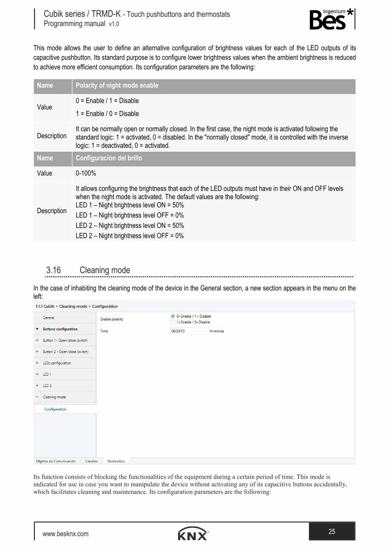
3.16 Cleaning mode
In the case of inhabiting the cleaning mode of the device in the General section, a new section appears in the menu on the left:
Its function consists of blocking the functionalities of the equipment during a certain period of time. This mode is indicated for use in case you want to manipulate the device without activating any of its capacitive buttons accidentally, which facilitates cleaning and maintenance. Its configuration parameters are the following:

Cubik series / TRMD-K - Touch pushbuttons and thermostats Programming manual v1.0
www.besknx.com 26
Name Enable polarity
Value 0 = Enable / 1 = Disable
1 = Enable / 0 = Disable
Description It can be normally open or normally closed. In the first case, the cleaning mode is activated following the standard logic: 1 = activated, 0 = disabled. In the "normally closed" mode, it is controlled with the inverse logic: 1 = deactivated, 0 = activated.
Name Time
Value Min: 0 sec. Max: 4 min and 15 sec.
Description It allows to configure the time during which the device will not receive orders from the user. After this time, the device will return to normal operation. The default value is 10 sec.
3.17 Advanced functions
If the advanced functions are enabled in the General menu, a new submenu appears on the left.
In this configuration menu it is possible to select what Arithmetic and logic or timers / counters blocks are enabled.
Name Arithmetic-logic block X
Values Enable / Disable
Description Allows to enable or disable each arithmetic and logic block.
Name Timer / counter block
Values Enable / Disable
Description Allows to enable or disable the each timer / counter blocks.

Cubik series / TRMD-K - Touch pushbuttons and thermostats Programming manual v1.0
www.besknx.com 27
Arithmetic and Logic block (ALU)
Name Operation
Values AND, NAND, OR, NOR, XOR, XNOR, NOT, BUFFER, == , != , <, > , <= , >= , + , - , *, / .
Description It allows to select the arithmetic or logic operation of the block: Logic operations:
- AND: Logic product - NAND: Negative logic product - OR: Logic addition - NOR: Negative logic addition - XOR: Exclusive logic addition - XNOR: Negative exclusive logic addition - NOT: Negation - BUFFER: Saves the input value in the output.
Comparison operation: - == : equality - != : inequality - < : smaller than - > : greater than - <= : smaller or equal than - >= : greater or equal than
Arithmetic operations: - + : addition - - : subtraction - * : multiplication
/ : division
Name Number of inputs
Values From 2 to 4
Description This parameter defines the number of inputs of the block. Depending on the type of operation it is allowed two or more inputs.
Name Input 1
Values Communication object / Constant value

Cubik series / TRMD-K - Touch pushbuttons and thermostats Programming manual v1.0
www.besknx.com 28
Description This parameter allows to select the type of the input 1, that can be a constant value or a value received from a communication object.
Name Format
Values 1 bit, 1 byte unsigned (dpt 5.001), 1 byte unsigned (dpt 5.010), 1 byte signed (6.*), 2 bytes unsigned (dpt 7,*), 2 bytes unsigned (dpt 8,*), 2 bytes float (dpt 9,*).
Description This parameter allows to select the size and format of the input 1. Depending on the type of operation different formats are allowed.
Name Input 2/3/4
Values 1 bit, 1 byte unsigned (dpt 5.001), 1 byte unsigned (dpt 5.010), 1 byte signed (6.*), 2 bytes unsigned (dpt 7,*), 2 bytes unsigned (dpt 8,*), 2 bytes float (dpt 9,*).
Description This parameter allows to select the size and format of the other inputs communication objects. Depending on the type of operation different formats are allowed.
Timer / counter block
Name Timer type
Values PWM, Limit, Cyclic
Description PWM: It generates a pulse width modulated output according to the period of time and a duty.

Cubik series / TRMD-K - Touch pushbuttons and thermostats Programming manual v1.0
www.besknx.com 29
Limit: It sends a bit telegram ‘1’ to the bus when a limit value is exceeded.
Ouput 1
0
Enable 1
0
Period X
0
Value
Time
X X
Ouput 1
0
Period T
0
Duty d
0
Value
Time
d
T T
d d
T
Cubik series / TRMD-K - Touch pushbuttons and thermostats Programming manual v1.0
www.besknx.com 30
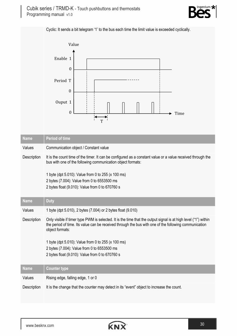
Cyclic: It sends a bit telegram ‘1’ to the bus each time the limit value is exceeded cyclically.
Name Period of time
Values Communication object / Constant value
Description It is the count time of the timer. It can be configured as a constant value or a value received through the bus with one of the following communication object formats: 1 byte (dpt 5.010): Value from 0 to 255 (x 100 ms) 2 bytes (7.004): Value from 0 to 6553500 ms
2 bytes float (9.010): Value from 0 to 670760 s
Name Duty
Values 1 byte (dpt 5.010), 2 bytes (7.004) or 2 bytes float (9.010)
Description Only visible if timer type PWM is selected. It is the time that the output signal is at high level (“1”) within the period of time. Its value can be received through the bus with one of the following communication object formats: 1 byte (dpt 5.010): Value from 0 to 255 (x 100 ms)
2 bytes (7.004): Value from 0 to 6553500 ms 2 bytes float (9.010): Value from 0 to 670760 s
Name Counter type
Values Rising edge, falling edge, 1 or 0
Description It is the change that the counter may detect in its “event” object to increase the count.
Ouput 1
0
Enable 1
0
Period T
0
Value
Time
T

Cubik series / TRMD-K - Touch pushbuttons and thermostats Programming manual v1.0
www.besknx.com 31
Name Limit value
Values From 0 to 65535
Description It is the number of events over which the counter sends the finish telegram.
Name Output behaviour
Values Send 1 when limit reached, Send counter value (5.010), Send counter value (7.001)
Description This parameter allows to select the format and behaviour of the counter output. It can be send a 1 when the count limit is reached or it can send the count value each time an event is detected.

Cubik series / TRMD-K - Touch pushbuttons and thermostats Programming manual v1.0
www.besknx.com 32
4 Installation
Square format Cubiks:
Vertical format Cubiks:

Cubik series / TRMD-K - Touch pushbuttons and thermostats Programming manual v1.0
www.besknx.com 33
Feed the low voltage lines (bus and inputs) in separate conduits of the 230 V power supply in order to ensure that there is sufficient insulation and thus avoid interference.
Do not connect the 230 V mains voltage or any other external voltage to any point on the bus or to the inputs.

Liability limitation: The present document is subject to changes or excepted errors. The contents are continuously checked to be according to the hardware and software but deviations cannot be completely excluded. Consequently, any liability for this is not accepted. Please inform us of any suggestion. Every correction will be incorporated in new versions of this manual.
Manual version: v1.0
Ingenium, Ingeniería y Domótica S.L.
Parque Tecnológico de Asturias, Parcela 50
33428 Llanera, Asturias, España
T (+34) 985 757 195
www.besknx.com
www.ingeniumsl.com