motoopcserver - motoman: doma€¦ · following settings must be done to allow communication...
TRANSCRIPT
MotoOPCServer

2 Introduction
Table of contents
1 INTRODUCTION 4
2 INSTALLATION AND BASIC CONFIGURATION 5
2.1 System requirements 5
2.2 Installation of MotoOPCServer 5
2.3 Robot controller settings 6
3 DCOM CONFIGURATION 8
4 KONFIGURATION DES MOTOOPCSERVERS 15
4.1 Common 16
4.2 Tracing 16
4.3 Devices 18
4.4 Example data 21
5 EXECUTING MOTOOPCSERVER 22
6 TROUBLESHOOTING 23
6.1 Service does not start 23
6.2 Connection problems 23
24.01.2006 Motoman robotec GmbH

Introduction 3
LIST OF FIGURES Figure 1 Installationsoptionen...............................................................................................5 Figure 2 MotoOPCServer service registration......................................................................6 Figure 3 Configuration of DCOM component Motoman NX100 OPC Server ....................8 Figure 4 Authentication level................................................................................................9 Figure 5 Identity....................................................................................................................9 Figure 6 Security.................................................................................................................10 Figure 7 Launch and Activation Permissions .....................................................................10 Figure 8 Access permissions...............................................................................................11 Figure 9 Configuration of OPC Enum component .............................................................11 Figure 10 DCOM properties MyComputer...........................................................................12 Figure 11 MyComputer Properties .......................................................................................12 Figure 12 COM Security.......................................................................................................13 Figure 13 Access Permission ................................................................................................13 Figure 14 Launch and Activation Permissions .....................................................................14 Figure 15 MotoOPCServer configuration software. .............................................................16 Figure 16 Device definition ..................................................................................................19 Figure 17 OPC client with Items provided by MotoOPCServer ..........................................21 Figure 18 MotoOPCServer service „MotomanOPCNX100“ ...............................................22 Figure 19 Communication Tester .........................................................................................23 Figure 20 Successful communication ...................................................................................23 LIST OF TABLES Table 1 System variables ...................................................................................................15 Table 2 TraceError.............................................................................................................17 Table 3 TraceWarning .......................................................................................................17 Table 4 TraceInfo ..............................................................................................................17 Table 5 TraceDebug ..........................................................................................................18 Table 6 Tracing, recommended settings............................................................................18 Table 7 Item definition file (Config-Typ1.csv) .................................................................19 Table 8 Columns of item definition file ............................................................................20 Table 9 Data type mapping................................................................................................20
Motoman robotec GmbH 24.01.2006

4 Introduction
1 Introduction OLE for Process Control – shortly called OPC – is based on COM / DCOM - technology. Main target of OPC is to simplify the connection between production applications and busi-ness/office applications. OPC has the following advantages ► Avoiding manufacturer dependence at hard- and software. ► Plug & Play configuration of data exchange. ► Multi-Client access to data sources. ► Network ability and Internet / Intranet. Basically OPC architecture consists of OPC server and OPC client components. MotoOP-
Server is an OPC server application for Motoman NX100 robot controllers. C An OPC server is an implementation of an OPC interface. OPC clients are accessing the ser-vices provided by OPC servers exclusively by using the interface which is defined by OPC pecification. An OPC server is the component which offers the following services: s
► Reading and Writing process data (Data Access) ► Observing Alarms with optional filters (Alarm & Event)
Security- und Batch functions
urrently MotoOPCServer solely provides an Data Access interface, which is read-only.
There are some OPC clients available for free for xample from http://www.matrikon.com.
► C OPC client software is not part of this software package. OPC clients are using the standard-ised methods provided by the OPC server.e
24.01.2006 Motoman robotec GmbH

Installation and basic configuration 5
2 Installation and basic configuration
2.1 System requirements
► Windows PC • WindowsXP/2000 • Ethernet TCP/IP network • Microsoft Internet Explorer (V4.72.2106.8) • Microsoft .NET Framework (provided on CDROM)
► Robot controller NX100 with suitable firmware (>3.30)
2.2 Installation of MotoOPCServer First check if your system meets the given system requirements. Install Microsoft .NET Framework if necessary. Installation of hardware key should be done after software installation. Otherwise there may be some problems in case of USB hardware keys. Before starting software installation procedure, login to windows system with local adminis-trative rights. Insert CDROM into CDROM drive of computer. The installation now starts automatically. If not use windows explorer, change to CDROM drive letter and run „cdstarter.exe“ directly from CDROM. After splash screen is displayed select installation of MotoOPCServer.
Figure 1 Installationsoptionen
Motoman robotec GmbH 24.01.2006
6 Installation and basic configuration
► Install OPC Core Components This option is activated by default, because OPC Core Components are necessary to run MotoOPCServer.
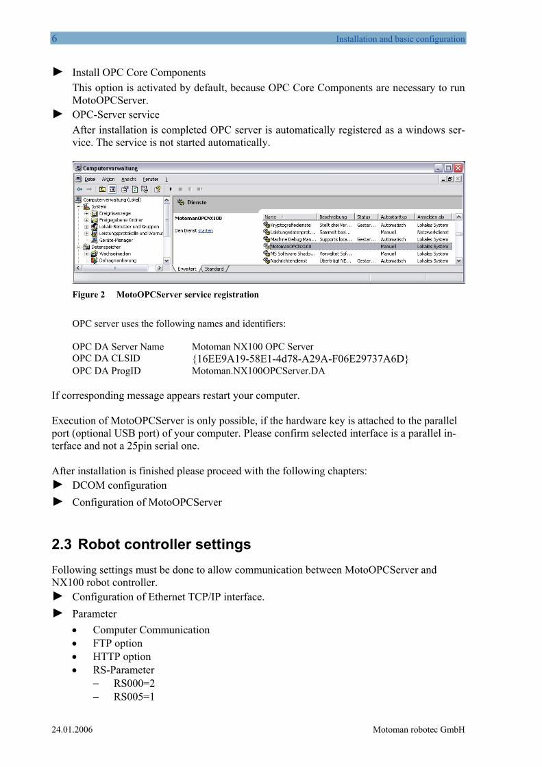
► OPC-Server service After installation is completed OPC server is automatically registered as a windows ser-vice. The service is not started automatically.
Figure 2 MotoOPCServer service registration
OPC server uses the following names and identifiers: OPC DA Server Name Motoman NX100 OPC Server OPC DA CLSID {16EE9A19-58E1-4d78-A29A-F06E29737A6D} OPC DA ProgID Motoman.NX100OPCServer.DA
If corresponding message appears restart your computer. Execution of MotoOPCServer is only possible, if the hardware key is attached to the parallel port (optional USB port) of your computer. Please confirm selected interface is a parallel in-terface and not a 25pin serial one. After installation is finished please proceed with the following chapters: ► DCOM configuration ► Configuration of MotoOPCServer
2.3 Robot controller settings Following settings must be done to allow communication between MotoOPCServer and NX100 robot controller.
n of Ethernet TCP/IP interface. ► Configuratio► Parameter
• Computer Communication
•
• FTP option • HTTP option
RS-Parameter − RS000=2 − RS005=1
24.01.2006 Motoman robotec GmbH

Installation and basic configuration 7
− RS007=1 − RS029=1
Motoman robotec GmbH 24.01.2006

8 DCOM configuration
3 DCOM configuration OPC security is based on DCOM security. DCOM uses security settings to protect server and client machines from unauthorized access. The security settings can be adjusted by a special tool called „dcomcnfg“. In the following chapter informations can be found how to configure OPC server and OPC client machines concerning DCOM secuirty. ► Creating user accounts
For the following example two domain accounts must be created: • 1 user account MotoOPCServer • 1 group account svc-MotoOPCServer
► Settings of OPC server • Run DCOMCNFG Tool by selecting Start=>run. Insert „dcomcnfg“ and hit Enter
key. • Select Component Services=>Computers=>MyComputer=>DCOM Con-
fig=>Motoman NX100 OPC Server=>Properties
Figure 3 Configuration of DCOM component Motoman NX100 OPC Server
• On the General tab set the Authentication level field to „Connect“.
24.01.2006 Motoman robotec GmbH

DCOM configuration 9
Figure 4 Authentication level
• On the Identity tab select „This user“ and specify the user account which was previ-ously created. Make sure that this user has sufficient rights to access the ressources. For example add this user to the group of local administrators.
Figure 5 Identity
• On the Security tab we have to customise both „Launch and Activation Permissions“ and „Access Permissions“:
Motoman robotec GmbH 24.01.2006

10 DCOM configuration
Figure 6 Security
• Add the user group we created earlier to the list and give them all permissions.
Figure 7 Launch and Activation Permissions
• Repeat this process for the Access permissions
24.01.2006 Motoman robotec GmbH

DCOM configuration 11
Figure 8 Access permissions
► Configuration of OPC Enum component.
This component allows a remote OPC client to browse the local machine. Configuration of this component is done in the same way as we configured the OPC server component. The sole exception is that we do not specify an account in the Identity tab. So System ac-count remains activated. In case of permissions it is also possible to use the “Everyone” group instead of specifying each OPC group like „svc-MotoOPCServer“.
Figure 9 Configuration of OPC Enum component
► Configuration of OPC clients
Motoman robotec GmbH 24.01.2006

12 DCOM configuration
• Run DCOMCNFG Tool by selecting Start=>Run. Insert „dcomcnfg“ and hit Enter key.
• Select Component Services=>Computers=>MyComputer=> Properties
Figure 10 DCOM properties MyComputer
• On the „General“ tab select „Connect“ and „Identifiy“.
Figure 11 MyComputer Properties
• On „COM-Security“ tab the following settings are necessary:
24.01.2006 Motoman robotec GmbH

DCOM configuration 13
Figure 12 COM Security
• Edit the default settings for access permissions and also the edit limits by adding
group „Anonymous Logon“.
Figure 13 Access Permission
• Now repeat this process for the Launch and Activation Permissions.
Motoman robotec GmbH 24.01.2006

14 DCOM configuration
Figure 14 Launch and Activation Permissions
24.01.2006 Motoman robotec GmbH

Konfiguration des MotoOPCServers 15
4 Konfiguration des MotoOPCServers For configuration of MotoOPCServer a configuration file “config.xml” is used. The file “con-fig.xml” is stored in the application folder. In addition to some basic settings like robot controller description and IP address, the file also contains the links to the optional items definition files. Without optional items the OPC server solely contains the default items which are listed in the table below.
System variables Type Description
Servo On VT_BOOL Servo active and ready
Step VT_BOOL Playback Mode: Step
1-Cycle VT_BOOL Playback Mode: 1-Cycle
Automatic VT_BOOL Playback Mode: Automatic
Teach VT_BOOL Operation Mode: Teach
Play VT_BOOL Operation Mode: Play
Remote VT_BOOL Operation Mode: Remote
Operating VT_BOOL Robot/Job is running
Operating at Safety Speed VT_BOOL Robot/Job is running with Safety Speed
Emergency Off VT_BOOL Emergency Off signal
Hold VT_BOOL Hold signal
Alarm VT_BOOL Alarm signal
Alarm data VT_BSTR Alarm number and Alarm message
Table 1 System variables
Editing of the file “config.xml” should be done by a special editor called MotoOPCCfg, which is also located in the application folder.
Motoman robotec GmbH 24.01.2006

16 Konfiguration des MotoOPCServers
Figure 15 MotoOPCServer configuration software.
MotoOPCCfg allows to edit or create the „config.xml“ file. After starting the software a new project is opened. If an already existing configuration should be changed the corresponding file must be loaded first. This is done by selecting menu item File->Open. Afterwards the configuration can be edited. To store the new configuration to file select File->Save. The configuration file is divided into different sections, which are described in the following chapters:
4.1 Common Here the delimiter can be specified which is used to separate alarm message data of robot con-troller, if there is more than one alarm.
4.2 Tracing In the tracing section the trace level can be specified. So the amount of trace data can be con-trolled.
24.01.2006 Motoman robotec GmbH
Konfiguration des MotoOPCServers 17
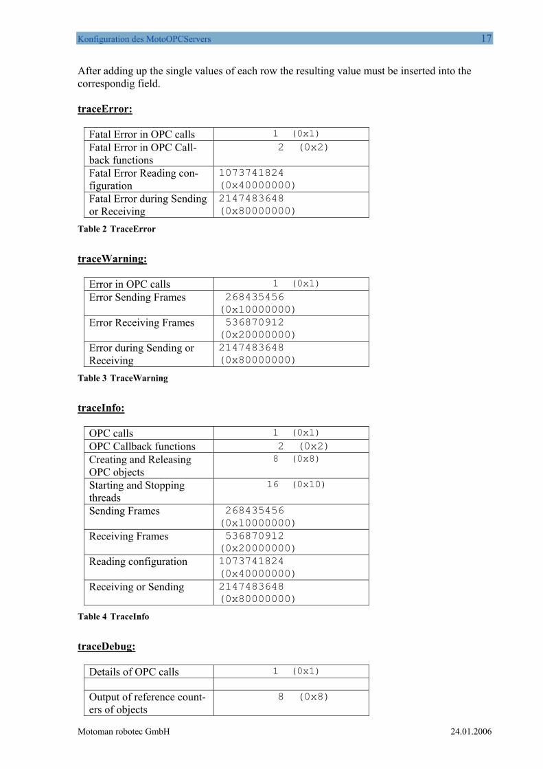
After adding up the single values of each row the resulting value must be inserted into the correspondig field. traceError:
Fatal Error in OPC calls 1 (0x1)
Fatal Error in OPC Call-back functions
2 (0x2)
Fatal Error Reading con-figuration
1073741824 (0x40000000)
Fatal Error during Sending or Receiving
2147483648 (0x80000000)
Table 2 TraceError
traceWarning:
Error in OPC calls 1 (0x1)
Error Sending Frames 268435456 (0x10000000)
Error Receiving Frames 536870912 (0x20000000)
Error during Sending or Receiving
2147483648 (0x80000000)
Table 3 TraceWarning
traceInfo:
OPC calls 1 (0x1)
OPC Callback functions 2 (0x2) Creating and Releasing OPC objects
8 (0x8)
Starting and Stopping threads
16 (0x10)
Sending Frames 268435456 (0x10000000)
Receiving Frames 536870912 (0x20000000)
Reading configuration 1073741824 (0x40000000)
Receiving or Sending 2147483648 (0x80000000)
Table 4 TraceInfo
traceDebug:
Details of OPC calls 1 (0x1) Output of reference count-ers of objects
8 (0x8)
Motoman robotec GmbH 24.01.2006

18 Konfiguration des MotoOPCServers
Details during starting and stopping of threads
16 (0x10)
Details during Sending of Frames
268435456 (0x10000000)
Details during Receiving of frames
536870912 (0x20000000)
Details during Sending or Receiving
2147483648 (0x80000000)
Table 5 TraceDebug
The following table gives an overview of the recommended settings. Additional traces should only be activated if necessary.
traceError Output of fatal errors (0xFFFFFFFF) traceWarning Output of warnings (0xFFFFFFFF) traceInfo Output of additional information
(0xFF000003) traceDebug Output of debugging information (0x0) traceFileEnable Activate/Deactivate tracing (true / false) traceFile1 Filename of first tracing output file. traceFile2 Filename of second tracing output file. traceFileMaxSize Maximum size of created files.
Table 6 Tracing, recommended settings.
4.3 Devices In the “Device” section the device which represents the data source is defined. For each de-vice a name and an IP address must be specified. Additionally the full pathname of an special item definition file can be specified here. This file contains those items which should be han-dled by OPC server in addition to the default items.
24.01.2006 Motoman robotec GmbH

Konfiguration des MotoOPCServers 19
Figure 16 Device definition
An example of an item definition file is given below. The file consists of 7 columns which are separated by tabulators.
Table 7 Item definition file (Config-Typ1.csv)
Rows starting with the ‘#’ character are comment lines. The remaining columns are described in the following table. Columns Description Item-Name Name of OPC item OPC-Type Type of OPC item.
Following OPC item types are supported: VT_BOOL VT_UI1 VT_I2 VT_I4 VT_R4 VT_BSTR
Motoman-Type Type of data source in robot controller. Following types are valid: 0: Byte variable (B-Variable) 1: Integer variable (I-Variable)
Motoman robotec GmbH 24.01.2006

20 Konfiguration des MotoOPCServers
2: Double (Integer) variable (D-Variable) 3: Real variable (R-Variable) 7: String variable (S-Variable) 101 IO Address (1 Bit) 108 IO Address group (8 Bit)
Address Address data of data source. In case of variables variable number is specified here (e.g. 50 for B050), in case of IO items starting address of IO block must be inserted here.
When using address groups keep in mind that starting address of group is only valid if it fits the condition: starting address=XXXXX+n*10
rw Valid access mode (currently not used !) r: read-only w: writing and reading
Comment Description of OPC item Table 8 Columns of item definition file
Following mapping between Motoman data types and OPC data types is possible:
Motoman data type OPC data typ Byte, Integer, Double, Real variable VT_BOOL, VT_UI1, VT_I2, VT_I4, VT_R4
String variable VT_BSTR IO’s VT_BOOL, VT_UI1, VT_I2, VT_I4, VT_R4
Table 9 Data type mapping
24.01.2006 Motoman robotec GmbH
Konfiguration des MotoOPCServers 21
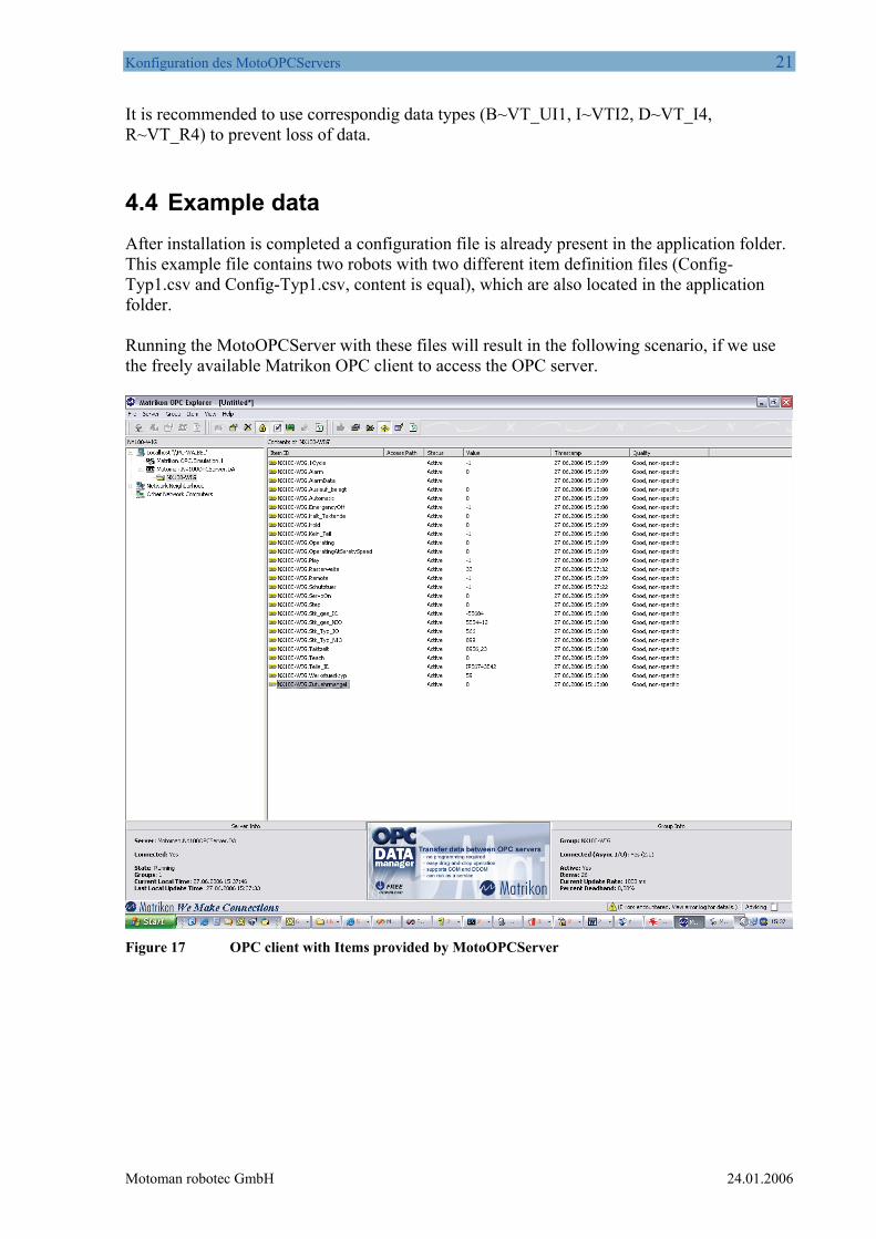
It is recommended to use correspondig data types (B~VT_UI1, I~VTI2, D~VT_I4, R~VT_R4) to prevent loss of data.
4.4 Example data After installation is completed a configuration file is already present in the application folder. This example file contains two robots with two different item definition files (Config-Typ1.csv and Config-Typ1.csv, content is equal), which are also located in the application folder. Running the MotoOPCServer with these files will result in the following scenario, if we use the freely available Matrikon OPC client to access the OPC server.
Figure 17 OPC client with Items provided by MotoOPCServer
Motoman robotec GmbH 24.01.2006
22 Executing MotoOPCServer
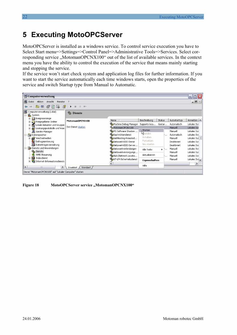
5 Executing MotoOPCServer MotoOPCServer is installed as a windows service. To control service execution you have to Select Start menu=>Settings=>Control Panel=>Administrative Tools=>Services. Select cor-responding service „MotomanOPCNX100“ out of the list of available services. In the context menu you have the ability to control the execution of the service that means mainly starting and stopping the service. If the service won’t start check system and application log files for further information. If you want to start the service automatically each time windows starts, open the properties of the service and switch Startup type from Manual to Automatic.
Figure 18 MotoOPCServer service „MotomanOPCNX100“
24.01.2006 Motoman robotec GmbH

Troubleshooting 23
6 Troubleshooting
6.1 Service does not start Check System and Application Event Log. There may be a problem with the hardware key.
6.2 Connection problems If status items are always displayed with quality „Bad“, the connection to corresponding robot should be checked. This can be done as follows: ► Open command line and execute ping command:
ping <IP address of NX100> If ping command is not successful check • physical connection between robot and pc (cabeling, switches etc.), • firewall settings if present (this OPC server uses port 80), • die Ethernet settings of robot.
► Execute tool „CommunicationTester.exe“. A shortcut is created in start menu. The tool itself is located in the application folder of MotoOPCServer.
Figure 19 Communication Tester
If the communication was successful following message is displayed. The two numbers displayed behind may differ according to the status of the NX100 robot controller:
Figure 20 Successful communication
Otherwise „Error“ is displayed. In this case check NX100 controller settings (refer to chapter Robot controller settings).
Motoman robotec GmbH 24.01.2006

24 Troubleshooting
Imprint MOTOMAN robotec GmbH Kammerfeldstraße 1 85391 Allershausen Germany Phone 00498166900 Fax 0049816690103
24.01.2006 Motoman robotec GmbH