motionblitzdirector2 ltr manual - aprolink.jp · manual motionblitz® director2 ltr high speed...
TRANSCRIPT

InstructionManual
MotionBLITZ® Director2 LTR
High Speed Video SystemVersion 1.6.3.0
Mikrotron GmbHLandshuter Str. 20-22 D-85716 UnterschleissheimGermany
Tel.: +49 89 726342 00Fax: +49 89 726342 99

1 General.....................................................................................................................................................................5
1.1 Essentials of MotionBLITZ®Director2.............................................................................................................51.2 Customer indications..........................................................................................................................................5
1.2.1 For customers in the U.S.A.........................................................................................................................................51.2.2 For customers in Canada............................................................................................................................................61.2.3 Pour utilisateurs au Canada........................................................................................................................................61.2.4 Life Support Applications..........................................................................................................................................6
1.3 Declaration of conformity..................................................................................................................................61.4 Remarks, Warnings............................................................................................................................................7
2 MotionBLITZ® in practice....................................................................................................................................8
2.1 The user interface...............................................................................................................................................82.2 Running multiple instances of the application....................................................................................................92.3 Program settings.................................................................................................................................................9
2.3.1 Changing the display rate...........................................................................................................................................92.3.2 Changing the playback speed.....................................................................................................................................92.3.3 Live view on connect..................................................................................................................................................92.3.4 Display info line.........................................................................................................................................................92.3.5 Show info panel........................................................................................................................................................102.3.6 Logarithmic slider mode...........................................................................................................................................102.3.7 Bayer interpolation...................................................................................................................................................102.3.8 Language..................................................................................................................................................................10
2.4 Connecting the camera.....................................................................................................................................102.5 Load and save camera profiles.........................................................................................................................102.6 Changing the pixel clock of the camera...........................................................................................................112.7 Startup profile...................................................................................................................................................122.8 Camera settings................................................................................................................................................12
2.8.1 Framerate, exposure time and frame size..................................................................................................................122.8.2 „Low Light“ mode....................................................................................................................................................122.8.3 Max Shutter..............................................................................................................................................................122.8.4 Adjust the ROI..........................................................................................................................................................122.8.5 Blacklevel.................................................................................................................................................................132.8.6 Gain (Only MC136x cameras)..................................................................................................................................132.8.7 Quad mode (Only MC136x cameras).......................................................................................................................142.8.8 Dynamic range adjustment.......................................................................................................................................142.8.9 Auto shutter..............................................................................................................................................................14
2.9 IO settings........................................................................................................................................................152.9.1 Grabber controlled sync............................................................................................................................................152.9.2 IRIG controlled sync (only for LTRs with IRIG Option)..........................................................................................152.9.3 External sync in........................................................................................................................................................152.9.4 Stop record on external trigger.................................................................................................................................152.9.5 Restart record after trigger stop................................................................................................................................162.9.6 Set marker on external trigger...................................................................................................................................162.9.7 Start burst on external trigger...................................................................................................................................162.9.8 Start record on external trigger.................................................................................................................................162.9.9 Enable ARM.............................................................................................................................................................162.9.10 Test input ports.......................................................................................................................................................162.9.11 ImageBLITZ® (Optional software feature)............................................................................................................16
2.9.11.1 ImageBLITZ® parameters..............................................................................................................................172.9.11.2 Gray difference and Relative object size.........................................................................................................172.9.11.3 Update ImageBLITZ® ..................................................................................................................................172.9.11.4 Stop record on ImageBLITZ®.......................................................................................................................172.9.11.5 Set marker on ImageBLITZ®.........................................................................................................................172.9.11.6 Start burst on ImageBLITZ®.........................................................................................................................17
2.10 Record settings...............................................................................................................................................182.10.1 Record directory.....................................................................................................................................................182.10.2 Record name...........................................................................................................................................................192.10.3 Available size.........................................................................................................................................................192.10.4 Optimize.................................................................................................................................................................192.10.5 Record Annotation.................................................................................................................................................192.10.6 Record mode...........................................................................................................................................................19
2.10.6.1 Ring................................................................................................................................................................19
MotionBLITZ® Director2 LTR Version 1.6.3.0 2

2.10.6.2 Until end of file..............................................................................................................................................192.10.6.3 Multi-sequence recording...............................................................................................................................19
2.10.7 Record size.............................................................................................................................................................202.10.8 Record frames.........................................................................................................................................................202.10.9 Record time............................................................................................................................................................202.10.10 Trigger settings.....................................................................................................................................................20
2.11 Multi camera setup (Optional).......................................................................................................................212.12 Record file format..........................................................................................................................................222.13 Image information field..................................................................................................................................23
3 Arrange a scene.....................................................................................................................................................24
3.1 Recording in non circular mode (Until end of file)..........................................................................................243.2 Recording in circular mode (Ring)...................................................................................................................24
3.2.1 Start recording..........................................................................................................................................................253.2.2 Stop recording..........................................................................................................................................................25
3.3 Playback of a sequence....................................................................................................................................253.3.1 Edit and save a sequence..........................................................................................................................................253.3.2 Select a sequence for playback and export................................................................................................................253.3.3 Remove a sequence..................................................................................................................................................253.3.4 Compute the timespan of a selected sequence..........................................................................................................26
4 The display window..............................................................................................................................................27
4.1 Dock/Undock the display window...................................................................................................................274.2 Display origin size............................................................................................................................................274.3 Fit to window....................................................................................................................................................274.4 Minimize/Maximize the window......................................................................................................................284.5 Show/Hide the toolbar......................................................................................................................................284.6 Zoom................................................................................................................................................................284.7 Change Brightness............................................................................................................................................284.8 Change Contrast...............................................................................................................................................284.9 Gamma Correction...........................................................................................................................................28
4.9.1 Gamma correction samples.......................................................................................................................................284.9.1.1 Gamma = 0.6, Image gets darker......................................................................................................................284.9.1.2 Gamma = 1.0, Unchanged................................................................................................................................294.9.1.3 Gamma = 2.0, Image gets brighter....................................................................................................................29
4.10 Image rotation................................................................................................................................................294.11 Image flip.......................................................................................................................................................294.12 Bayer adjustment (White balance).................................................................................................................29
4.12.1 Adjust white balance manually...............................................................................................................................304.12.2 Adjust white balance automatically........................................................................................................................30
4.13 Display RAW image data...............................................................................................................................304.14 Edit the info line.............................................................................................................................................314.15 Show Histogram Window..............................................................................................................................314.16 Add image marker..........................................................................................................................................314.17 Show grid lines...............................................................................................................................................314.18 View the RGB Values....................................................................................................................................314.19 Revert changes...............................................................................................................................................32
5 Image export..........................................................................................................................................................33
5.1 Supported export formats.................................................................................................................................335.1.1 BMP.........................................................................................................................................................................335.1.2 JPG...........................................................................................................................................................................335.1.3 PNG..........................................................................................................................................................................335.1.4 TIFF.........................................................................................................................................................................335.1.5 DNG (RAW format).................................................................................................................................................335.1.6 AVI...........................................................................................................................................................................335.1.7 DAT..........................................................................................................................................................................33
5.2 The Image Export Dialog.................................................................................................................................345.2.1 Selected images........................................................................................................................................................345.2.2 Export directory........................................................................................................................................................345.2.3 Export name.............................................................................................................................................................345.2.4 Export format...........................................................................................................................................................34
MotionBLITZ® Director2 LTR Version 1.6.3.0 3

5.2.5 Export size................................................................................................................................................................345.2.6 Export comment.......................................................................................................................................................35
5.3 Additional export file.......................................................................................................................................35
6 Image import.........................................................................................................................................................36
6.1 Open multiple files side by side.......................................................................................................................366.2 Sync record files...............................................................................................................................................37
7 IRIG-B time code receiver (Optional).................................................................................................................38
8 I/O Board...............................................................................................................................................................39
8.1 Pinning of the 15 pin D-Sub connector............................................................................................................408.2 Example schematics.........................................................................................................................................41
8.2.1 Connection of one input...........................................................................................................................................418.2.1.1 Light barrier with NPN transistor.....................................................................................................................418.2.1.2 Light barrier with PNP transistor......................................................................................................................42
8.2.2 Connecting more Inputs............................................................................................................................................438.2.2.1 Opto inputs - connected to relays or NPN transistors.......................................................................................438.2.2.2 Opto inputs - connected to relays or PNP transistors........................................................................................438.2.2.3 Opto inputs - random access.............................................................................................................................44
8.2.3 Connection to the outputs.........................................................................................................................................448.3 Schematic of the Opto I/O Board.....................................................................................................................45
MotionBLITZ® Director2 LTR Version 1.6.3.0 4

1 General
Congratulations! MotionBLITZ® is an excellent choice, because it’s a extremely versatile, advanced and self contained digital camera system. Mikrotron Deutschland GmbH has combined progressive camera technology with software which is very easy to operate. Thus MotionBLITZ® is the ideal solution for high speed recording. This manual provides information about the features and operating modes of MotionBLITZ®.
The MotionBLITZ® system is configured for best performance. Please do not change any system settings to avoid performance loss.
1.1 Essentials of MotionBLITZ®Director2
With the MotionBLITZ® software rapidly moving or explosive processes can be continuously recorded and stored at up to 35000 images per second and can be displayed and analysed in detail immediately after the record end.
For displaying the frames there are 2 possibilities, depending on the LTR type:
LTR1: via the primary DVI and an additional second VGA output
LTR1P, LTR2P, LTR3P and LTR5P: via the inbuilt monitor and an additional second VGA output
i.e. a second, parallel monitor could be used for all LTR types.
1.2 Customer indications
1.2.1 For customers in the U.S.A.This equipment has been tested and found to comply with the limits for a Class A digital device, pursuant to Part 15 of the FCC Rules. These limits are designed to provide reasonable protection against harmful interference when the equipment is operated in a commercial environment. This equipment generates, uses, and can radiate radio frequency energy and, if not installed and used in accordance with the instruction manual, may cause harmful interference to radio communications. Operation of this equipment in a residential area is likely to cause harmful interference in which case the user will be required to correct the interference at his own expense. You are cautioned that any changes or modifications not expressly approved in this manual could void your authority to operate this equipment. The shielded interface cable recommended in this manual must be used with this equipment in order to comply with the limits for a computing device pursuant to Subpart J of Part 15 of FCC Rules.
MotionBLITZ® Director2 LTR Version 1.6.3.0 5

1.2.2 For customers in CanadaThis apparatus complies with the Class A limits for radio noise emissions set out in Radio Interference Regulations.
1.2.3 Pour utilisateurs au CanadaCet appareil est conforme aux normes Classe A pour bruits radioélectriques, spécifiées dans le Règlement sur le brouillage radioélectrique.
1.2.4 Life Support ApplicationsThese products are not designed for use in life support appliances, devices, or systems where malfunction of these products can reasonably be expected to result in personal injury. Mikrotron customers using or selling these products for use in suchapplications do so at their own risk and agree to fully indemnify Mikrotron for any damages resulting from such improper use or sale.
1.3 Declaration of conformity
Manufacturer:Mikrotron GmbH
Address:Landshuterstr. 20-2285716 UnterschleissheimGermany
Product: MotionBLITZ® LTR 1 / 2 High Speed Long Time Recording System
The dedicated products conform to the requirements of the Council Directive 2004/108/EC and 2006/95/EC for the approximation of the laws of the Member States relating to electromagnetic consistency.The following standards were consulted for the conformity testing with regard to electromagnetic consistency and safety.
.
EC Regulation DescriptionEN 60950-1 Low Voltage Directive EN 61000-6-3 EMC electromagnetic consistency EN 61000-6-1 Immunity
Unterschleissheim, June 1th 2012
Mikrotron GmbH
Jürgen ZimmermannManaging Director, Mikrotron GmbH
MotionBLITZ® Director2 LTR Version 1.6.3.0 6

1.4 Remarks, Warnings
This document contains important remarks and warnings. See the corresponding symbols:
Important remark
Attention, Warning
MotionBLITZ® Director2 LTR Version 1.6.3.0 7

2 MotionBLITZ® in practice
The full range of functions available and all camera parameters may be set by means of the MotionBLITZ® software. The user interface is organized in three parts.On the left side, there is the control panel for the camera and program settings, in the middle the display window and below the panel for controlling the application. Each part may be enlarged or minimized, undocked and docked again.
2.1 The user interface
The camera is completely controlled through the user interface. All parameters of the camera for recording, playback and saving the frames after recording may be adjusted here. After recording stored image sequences can be edited immediately. The software can be started by double clicking on the Director2 symbol on the PC desktop or by selecting the application in the windows start menu. After camera selection (by clicking on the appropriate entry in the list of „Available cameras“ and establishing the connection by clicking on “Connect”) the following screen mask will appear.
Select modes of operation or change parameters by pressing a command button or by selecting an item in an expander control (e.g. camera settings). If the mouse cursor is moved slowly over some of the command buttons and symbols, information about this object will be displayed ("tool tip text").
MotionBLITZ® Director2 LTR Version 1.6.3.0 8

2.2 Running multiple instances of the application
If your system is supplied as multi camera system you can run each camera in a standalone instance of the application. To do this create a shortcut for each instance and start the application with the grabber ID as parameter. For grabber 0 enter the following in the target of the shortcut (...\MotionBLITZDirector2.exe Grabber#0). For grabber 1 (...\MotionBLITZDirector2.exe Grabber#1).
2.3 Program settings
2.3.1 Changing the display rateAdjusts the display rate in fps. To reduce the CPU load on slow systems the display rate can be lowered. The maximum possible display rate depends on the used hardware (CPU, Graphics card).
2.3.2 Changing the playback speedAdjusts the playback speed in fps for an opened image sequence. If it's not possible to display each frame for a given speed, frames get skipped.
2.3.3 Live view on connectAutomatically sets the camera into live mode after the connection is established.
2.3.4 Display info lineAppends additional information to the bottom of each frame. The info line can contain various camera and record parameters (Framerate, shuttertime, IRIG timestamp (optional), ...).
If the “Info Line” is enabled it will be appended to the exported frames. (Not for RAW export formats)
MotionBLITZ® Director2 LTR Version 1.6.3.0 9

2.3.5 Show info panelDisplays the info panel at the top of the main window. The info panel shows basic information about the current camera settings and record information if a recorded sequence is opened. The sync options for multiple cameras and files are also displayed on this panel if available.
2.3.6 Logarithmic slider modeUse a logarithmic scale for the shutter slider and the playback speed slider.
2.3.7 Bayer interpolation
Only active for color cameras and bayer image data.
Selects the quality of the BAYER to RGB color conversion. Please note that the computation time increases with the quality. For slow systems it’s recommended to use the lowest quality in order to achieve a higher display rate. During a recording the lowest quality is automatically used for best performance. Please note that the classification of the quality levels can not be valid for all image data. At certain images a lower quality level can lead to a better optical result.
2.3.8 LanguageChanges the language of the application. To add further languages the language files can be freely edited.
2.4 Connecting the camera
On application startup the camera appears in the control on the left side. To connect the camera simply double click on the camera or use the connect button.
If the camera can’t be connected check if the camera is powered on and the cabling from the grabber to the camera is correct (FULL, BASE);
2.5 Load and save camera profiles
A camera profile is a set of all camera parameters that may be changed by the user.The profiles are stored in XML format. If you save a profile, the actual camera settings will be written to a file. If you load a profile, the parameters in the appropriate file are read and sent to the camera. Loading and saving of profiles is accomplished by clicking on the „Load profile“ and „Save Profile“ button.
MotionBLITZ® Director2 LTR Version 1.6.3.0 10

2.6 Changing the pixel clock of the camera
For special environments (fiber repeater) the cameras pixel clock has to be lowered or set to a specific value to work correctly. To do this the cameras power up profile has to be adjusted.Download and install the 64 bit version of the MC_ControlTool for MC136x / MC301x cameras from the following website (http://www.mikrotron.de/index.php?de_downloadfiles).Close the MBDirector2 application if running and make sure the camera is correctly cabled. Now start the MC_ControlTool and connect the camera.
Go to the MISC tab and select the “factory profile 7” from the “Load profile” selection. Then click “Load”. After the profile is loaded switch to the Image Control tab.
After loading the factory profile change no other settings than the ones that are specified here
For MC136x cameras: Switch the tab mode to 10 x 8 Choose the wanted pixel clock
For MC301x cameras: Choose the wanted pixel clock
MotionBLITZ® Director2 LTR Version 1.6.3.0 11

After the changes are done switch back to the MISC tab and select the “power up profile” from the “Save actual profile” selection. Then click “Save”. Now the camera starts always with the selected pixel clock. Close the MC_ControlTool.To prevent Director2 LTR from loading the base factory profile on startup a config file has to be adjusted manually. Switch to the following directory on your LTR system.“C:\Users\Username\AppData\Roaming\MotionBLITZDirector2 LTR” (You have to set hidden folders to be visible). Open the “CLGlobal.cfg” file and set the following section to 1: <UsePowerUpProfile>1</UsePowerUpProfile>
After you have made these changes you can start the Director2 LTR app and connect your camera. The camera runs now at the predefined pixel clock...
2.7 Startup profile
The last used camera setting is automatically loaded when the application is started.
2.8 Camera settings
2.8.1 Framerate, exposure time and frame sizeThe framerate and exposure time may be adjusted with the slider „Framerate [fps]“ and „Shutter [µs]“ or you enter the values via keyboard in the corresponding input fields. The adjustments will take effect immediately.
2.8.2 „Low Light“ modeIn low light mode the camera's exposure-time is extended up to 99,9 milliseconds in order to increase it's sensitivity. This mode is good for setting up the frame size and the focus in “Live” mode. Select your exposure time with the slider " Shutter [µs]" or input it directly in the appropriate number-field. Low light mode will be automatically finished if a recording is started.
2.8.3 Max ShutterIf this check box is activated, the maximal exposure time for the actual frame size and frame rate will be automatically used.
2.8.4 Adjust the ROI
MotionBLITZ® Director2 LTR Version 1.6.3.0 12

By clicking on „Adjust ROI“ the so called “Region Of Interest” or image section can be freely changed.
Enter the values for x-position („Offset X“), y-position („Offset Y“), width („Width“) or height („Height“) directly into the text fields.
Move the green bounding box in the left control Move the red rectangle onto the live image
By clicking on „Apply ROI“, the adjustments will be applied to the camera.
2.8.5 BlacklevelThis parameter adjusts the base black level of the cameras sensor. The base black level must be set to a value between 0 and 255. If correctly adjusted the sensor will deliver a pixel value of ~0 (which means totally black) for a complete black image. If the value is too big, the sensor will deliver a pixel value above 0 (which means gray).If the value is too small, the sensor will deliver a pixel value 0 (totally black) for images, that are gray and not completely black.In live mode, close the lens of the camera for getting a completely black image. Adjust the black level until the black line in the Luminance selection touches the 0-line of the diagram.
2.8.6 Gain (Only MC136x cameras)The gain may be adjusted with the slider „Digital Gain”. Factors 1 to 4 are allowed. Please note that the image quality decreases the more the gain is increased.
MotionBLITZ® Director2 LTR Version 1.6.3.0 13

2.8.7 Quad mode (Only MC136x cameras)MC136x cameras provide the „Quad Mode“. In this mode there can be a quadruple higher recording time achieved together with a higher possible framerate without changing the image section (width and height of the image). The only drawback is a little decrease in image quality. The quad mode is marked with a (Q) beside the framerate label.By clicking on the check box „Enable ”Quad Mode “ in the expander control „AdvancedSettings“ this mode will be activated. Please note that this adjustment will take a fewseconds. Without “Quad Mode“, the full quality of the image without the increased frame rate and recording time will be delivered.
2.8.8 Dynamic range adjustmentWith the “Dynamic range adjustment” you may adjust the sensor’s characteristic in order to avoid overexposure of very bright parts in the image.If the slider is moved to 1, the sensor’s characteristic is linear, normal illuminated scenes will be displayed well.If there are very bright areas in the scene, then the image will be overexposed, details of the motif will be lost. In this case you should move the slider to the right (up to 99 max.) whereby details in bright parts of the image will become visible again. The correct setup value depends on the brightness spreading of your motif. In normal illuminated scenes you should use “1”.
2.8.9 Auto shutter
This feature automatically adjusts the exposure time depending on the object brightness. This results in a constant image brightness. Brightness: Desired image brightness [0..255] Percent: Percent of the image that will be used for brightness computationHysteresis: Readjustment range. Can be set to prevent flickeringSpeed: The speed of the brightness adjustmentMin: Min allowed shutter valueMax: Max allowed shutter value
MotionBLITZ® Director2 LTR Version 1.6.3.0 14
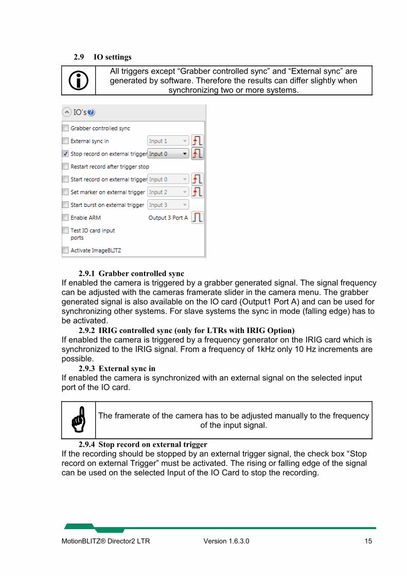
2.9 IO settings
All triggers except “Grabber controlled sync” and “External sync” are generated by software. Therefore the results can differ slightly when
synchronizing two or more systems.
2.9.1 Grabber controlled syncIf enabled the camera is triggered by a grabber generated signal. The signal frequency can be adjusted with the cameras framerate slider in the camera menu. The grabber generated signal is also available on the IO card (Output1 Port A) and can be used for synchronizing other systems. For slave systems the sync in mode (falling edge) has to be activated.
2.9.2 IRIG controlled sync (only for LTRs with IRIG Option)If enabled the camera is triggered by a frequency generator on the IRIG card which is synchronized to the IRIG signal. From a frequency of 1kHz only 10 Hz increments are possible.
2.9.3 External sync inIf enabled the camera is synchronized with an external signal on the selected input port of the IO card.
The framerate of the camera has to be adjusted manually to the frequency of the input signal.
2.9.4 Stop record on external triggerIf the recording should be stopped by an external trigger signal, the check box “Stop record on external Trigger” must be activated. The rising or falling edge of the signal can be used on the selected Input of the IO Card to stop the recording.
MotionBLITZ® Director2 LTR Version 1.6.3.0 15
2.9.5 Restart record after trigger stopThis feature is only available if “Stop record on external Trigger” is enabled. The record is automatically restarted after the last record is stopped by an external signal. Each new record creates a new record file. This mode can only be used if the record mode is set to ring. For multi camera systems all connected cameras are restarted.
2.9.6 Set marker on external triggerAllows to mark positions while recording. After the record is stopped the positions of the markers can be accessed directly.
2.9.7 Start burst on external triggerThere are two burst modes available
Record while the trigger on the selected input port is active. Record a predefined number of frames when the trigger occurs.
2.9.8 Start record on external triggerIf the recording should be started by an external signal, the check box “Start record on external Trigger” must be activated. The rising or falling edge of the signal can be used on the selected Input of the IO Card to start recording. For multi camera systems all connected cameras are set to record mode.
2.9.9 Enable ARMOutputs a signal on Output 3 Port A of the IO Card as long as the recording is running. Depending on the setting the signal can be high or low.
2.9.10 Test input portsShows the current state of the IO input ports (red = high, green = low).
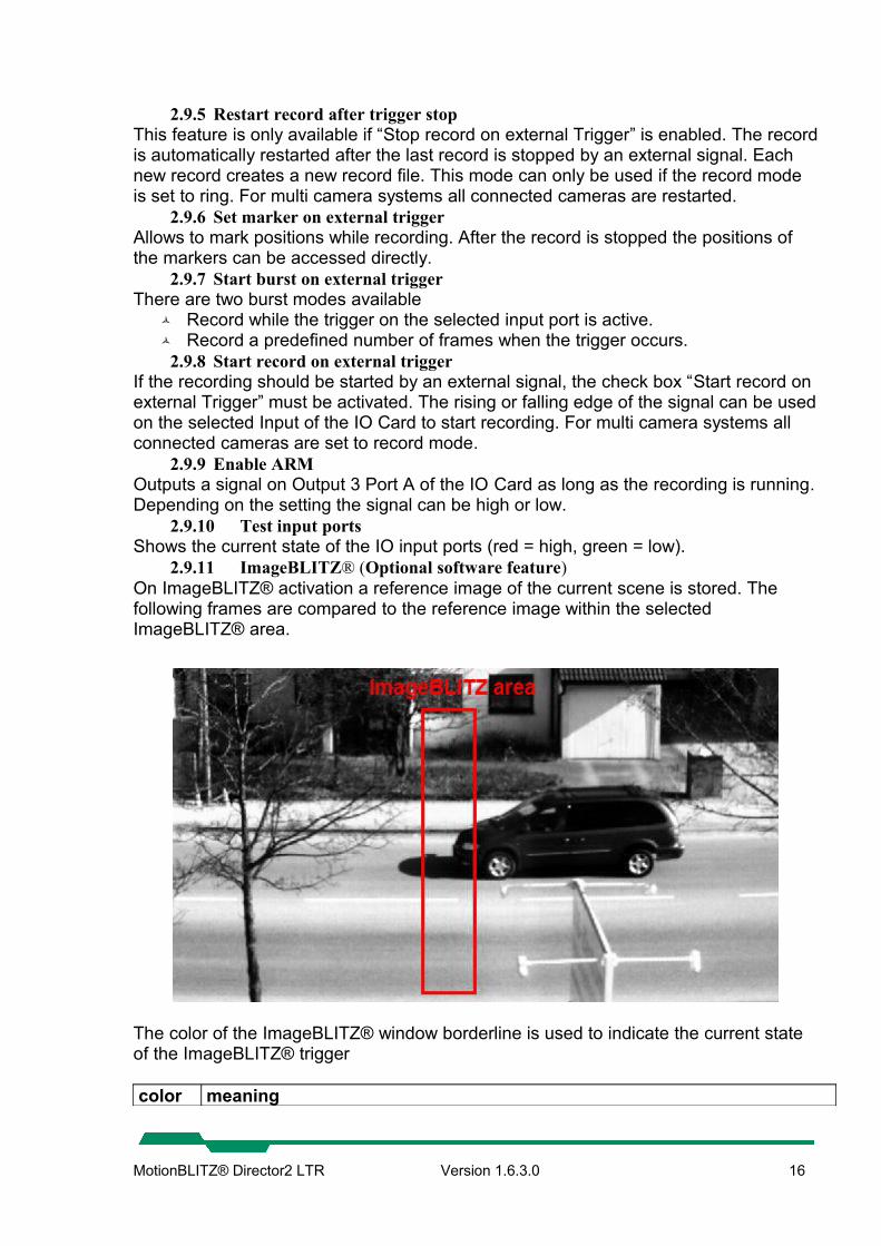
2.9.11 ImageBLITZ® (Optional software feature)On ImageBLITZ® activation a reference image of the current scene is stored. The following frames are compared to the reference image within the selected ImageBLITZ® area.
The color of the ImageBLITZ® window borderline is used to indicate the current state of the ImageBLITZ® trigger
color meaning
MotionBLITZ® Director2 LTR Version 1.6.3.0 16

Green ImageBLITZ® is active and waiting for a trigger situationRed ImageBLITZ® is active and has triggeredYellow ImageBLITZ® state undetermined (During preview of a recorded sequence)
2.9.11.1 ImageBLITZ® parameters
2.9.11.2 Gray difference and Relative object sizeCalibrates the ImageBLITZ® trigger. The parameters can be set automatically by using the auto adjust function. For example: Gray difference is set to 100 and relative object size is set to 20. The trigger is released when 20 percent of the pixels inside the selected area show a gray value difference of 100 compared to the reference image.
2.9.11.3 Update ImageBLITZ® Updates the ImageBLITZ® reference frame to the current scene.
2.9.11.4 Stop record on ImageBLITZ®Stops the recording when the ImageBLITZ state changes.
2.9.11.5 Set marker on ImageBLITZ®Allows to mark a position in the current running record by ImageBLITZ®. The set markers can be directly selected during playback of the sequence. The number of markers is limited to 1024.
2.9.11.6 Start burst on ImageBLITZ®This feature supports two modes:
Record while the state of the ImageBLITZ® is triggered or non triggered Record a predefined number of frames when the ImageBLITZ® state changes.
MotionBLITZ® Director2 LTR Version 1.6.3.0 17

2.10 Record settings
2.10.1 Record directoryAllows to create a new record directory or to browse/delete existing record files.
The record root drive can’t be changed.
MotionBLITZ® Director2 LTR Version 1.6.3.0 18

2.10.2 Record nameUsed name for the next record file. The current date and time is automatically appended to the filename (RECORDNAME_DATE_TIME If no record name is specified the default name is used (DIRECTORY_DATE_TIME).
2.10.3 Available sizeDisplays the current available record size. If the record size limit of the system is reached manually delete files from the record directory to get free space. After that click the refresh button to update the user interface.
2.10.4 OptimizeStarts to defragment the record drive. This process is automatically started on every application and record start and is needed for performance reasons.
To reduce the defragmentation time on record start the process can be started manually.
2.10.5 Record AnnotationWrites the entered text into the header of the next record file. The size of the text is limited to 512 characters. The annotation can be used to store arbitrary information.
2.10.6 Record mode2.10.6.1 Ring
The record runs in circular mode. If the selected record size is reached the oldest frames get overwritten by the newest until the recording is stopped.The recording can be stopped by
the “Stop” button or the F12 key. an external stop signal. ImageBLITZ®
2.10.6.2 Until end of fileThe record runs until the selected record size is reached. The record then automatically stops. Alternatively the record can be stopped by
the “Stop” button or the F12 key.2.10.6.3 Multi-sequence recording
See chapter “Restart record after trigger stop”
MotionBLITZ® Director2 LTR Version 1.6.3.0 19

2.10.7 Record sizeThe selected record size for the next recording. The minimum file size is fixed to 500MB. The maximum file size depends on the used system and the available space on the record directory.
2.10.8 Record framesThe number of frames that can be recorded for a given record size.
2.10.9 Record timeThe record time for a given record size in [HH:MM:SS]HH: HoursMM: MinutesSS: Seconds
2.10.10 Trigger settingsNumber of frames to be recorded after the trigger occurs. This feature is only available in ring mode. The recording must be stopped by an external signal or by F12 - key to achieve the trigger settings. Otherwise the recording is stopped immediately.
The recording must be stopped by an external signal or by F12 - key to achieve the trigger settings.
MotionBLITZ® Director2 LTR Version 1.6.3.0 20

2.11 Multi camera setup (Optional)
If available the LTR system can run more than one camera at the same time. Each camera has it's own record directory and can be setup independently. The features of the current selected camera are displayed onto the left panel (Camera settings, IO's, Record settings). To synchronize multiple cameras adjust the IO settings for each camera. Use the sync modes (Grabber controlled, External sync) to synchronize the image acquisition and/or the “Stop record on external trigger” setting to stop the recording by a common signal. Please note that you have to adjust the settings for each camera. A global information of all camera settings is displayed in the info panel at the top of the applications window. After the recording is finished all recorded files are displayed side by side.
MotionBLITZ® Director2 LTR Version 1.6.3.0 21

2.12 Record file format
All record files are stored in a Mikrotron proprietary .dat format. The format contains a file header (8192 bytes). After the header the raw image data is written sequentially.
DWORD Offset to image dataDWORD Header versionChar[20] Header signatureChar[30] Record start timeChar[100] Camera nameChar[100] Camera manufacturerChar[100] Camera modelChar[100] Camera firmwareChar[100] Camera serialChar[1024] User defined commentDWORD Camera countDWORD Offset X in pixelsDWORD Offset Y in pixelsDWORD Width in pixelsDWORD Height in pixelsDWORD Image size in bytesDWORD Record framerate in fpsDWORD Record exposure time in µsDWORD Used data format
MONO1 = 0, GRAY4 = 1, GRAY8 = 2, BAYER_GRBG = 3, BAYER_GBRG = 4, BAYER_RGGB = 5, BAYER_BGGR = 6, COLOR_RGB32 = 7 MONO1_QUAD = 8, GRAY4_QUAD = 9, GRAY8_QUAD = 10, BAYER_GRBG_QUAD = 11, BAYER_GBRG_QUAD = 12, BAYER_RGGB_QUAD = 13, BAYER_BGGR_QUAD = 14, COLOR_RGB32_QUAD = 15
Double Bayer factor (Red)Double Bayer factor (Green)Double Bayer factor (Blue)Double Gamma (Red)Double Gamma (Green)Double Gamma (Blue)UInt64 Number of framesUint64 Start frameUint64 Trigger frameUint64 Trigger tick countInt64 internalDWORD InternalDWORD ImageBLITZ® offset X in pixels (Optional since header version 2)DWORD ImageBLITZ® offset Y in pixels (Optional since header version 2)DWORD ImageBLITZ® width in pixels (Optional since header version 2)DWORD ImageBLITZ® height X in pixels (Optional since header version 2)Int32 IRIG available (Optional since header version 3)
MotionBLITZ® Director2 LTR Version 1.6.3.0 22

Int64 TickCountFrequency high performance counter (since header version 3)
2.13 Image information field
Each recorded frame holds various information in the first line of the image.
Byte 0..1 Image counter [1....65535]Byte 2..3 free, currently not in useByte 4..7 DWORD, High Performance counter Ticks (HighPart)Byte 8..11 DWORD, High Performance counter Ticks (LowPart)BYTE 12 Digital Inputs 0-7. Lowest bit IO:0, Highest bit IO:7BYTE 13 Used for image markersBYTE 14 Optional - Used for ImageBLITZ®BYTE 15 Optional - Used for ImageBLITZ®BYTE 16..19 Optional – Used for IRIG timestamp (UTC seconds)BYTE 20..23 Optional – Used for IRIG (UTC microseconds)
MotionBLITZ® Director2 LTR Version 1.6.3.0 23

3 Arrange a scene
Click on the "Live"-Button to get a live-image from the camera. The camera may now be focused and adjusted to the details of the scene. You may use the low light mode to increase the camera's sensitivity (available only in live mode because on the other side the framerate will be decreased!)
3.1 Recording in non circular mode (Until end of file)
Non-circular record mode is selected in the expander control "Record settings" => “Record mode“ => "Until end of file". To start, click on the “Record Button. During recording, the recorded frames are displayed simultaneously. After recording, the last recorded frame will be displayed.
3.2 Recording in circular mode (Ring)
Circular record mode is selected in the expander control "Record settings" => “Ring”. The circular mode should be used if a trigger is applied. The trigger may be
The F12 key ImageBLITZ® a trigger signal on the IO card, see chapter “Stop record on external trigger”
A trigger is necessary if images are needed before and/or after an event. The trigger defines the point of time of your event.The circular mode is defined by the following parameters
The number of frames (time span) before the trigger (Pre) The number of frames (time span) after the trigger (Post)
While recording a preview of the recorded frames is displayed by the software. On record stop the first frame after the trigger gets automatically displayed. The timestamps will be set in relation to the moment of the trigger event, i.e. the first frame after the trigger is set to 0 ms. Negative values indicate that the displayed frame was recorded before the trigger, positive values indicate frames after the trigger, called “post-trigger frames”
MotionBLITZ® Director2 LTR Version 1.6.3.0 24

3.2.1 Start recordingThe recording can be started by
the record button in the bottom control the F5 key an external signal on the IO card, see chapter “Start record on external trigger”
3.2.2 Stop recordingThe recording can be stopped by
the stop button in the bottom control the F12 key ImageBLITZ® an external signal on the IO card, see chapter “Stop record on external trigger”
Depending on the selected post trigger frames it could take a while until the recording process is stopped.
3.3 Playback of a sequence
The recorded frames can be accessed and displayed immediately after the recording is finished. The last recorded file is automatically loaded on application startup if available.
Use the play-forward and play-backward buttons to start the playback of the images. To step through the single images use the step buttons beside the scrollbar or the mouse wheel. Alternatively use the arrow keys. The playback speed can be adjusted in the program settings menu.
The scrollbar can also be used to view the images. The number of the current image along with the time stamp relative to the trigger frame is displayed at the bottom right of the control. If you want to jump directly to the trigger frame (frame after the trigger occurred) use the “Jump to trigger” button. To jump to a frame or a time stamp directly enter the value beside the Jump to trigger button.
3.3.1 Edit and save a sequenceSince not all recorded frames are always needed it’s possible to select an arbitrary sequences from the recording for playback and storage.
3.3.2 Select a sequence for playback and exportTo mark the start of a sequence press the “C” Key. To mark the end of a sequence press the “C” Key again. There can be arbitrary sequences selected. See picture below.
3.3.3 Remove a sequence
MotionBLITZ® Director2 LTR Version 1.6.3.0 25

To remove a single sequence move the scrollbar to the sequence until it’s selected and then click “Sequence options”->”Remove current selection”. To remove all the sequences click “Remove all selections”.The selected sequences are used for playback and for image export. Simply click save to start the image export dialog.
3.3.4 Compute the timespan of a selected sequenceTo compute the timespan of a sequence move the scrollbar to the sequence until it’s selected and the click “Sequence options”->”Compute timespan”.
MotionBLITZ® Director2 LTR Version 1.6.3.0 26

4 The display window
All image processing functions are available through the display window. The name of the current file is shown in the windows title.
4.1 Dock/Undock the display window
Depending on the current state of the window it is docked or undocked. In undocked state the window can be moved and resized. In docked state the window is fixed.
4.2 Display origin size
Displays the origin size of the image.
4.3 Fit to window
Fits the image to window (Only if the image is greater than the display area).
MotionBLITZ® Director2 LTR Version 1.6.3.0 27

4.4 Minimize/Maximize the window
Depending on the current state the window is maximized or minimized.
4.5 Show/Hide the toolbar
Depending on the current state the windows toolbar is shown or hidden. If the window is minimized the toolbar is automatically hidden.
4.6 Zoom
The image can be zoomed by the mouse wheel or by clicking the zoom button in the toolbar. If the button in the toolbar is clicked a control panel is shown at the bottom of the window. To reset the zoom simply click the mouse wheel over the image.
4.7 Change Brightness
Changes the brightness of the displayed image. The control panel is shown at the bottom of the window.
4.8 Change Contrast
Changes the contrast of the displayed image. The control panel is shown at the bottom of the window.
4.9 Gamma Correction
If you want to exponentially adapt the percentage brightness of the image you can use the gamma correction. The adjust panel is shown at the bottom of the window. A gamma value of 1 leaves the brightness unchanged. Values greater than 1 let dark parts become brighter. Values smaller than 1 let bright parts become darker.
4.9.1 Gamma correction samples4.9.1.1 Gamma = 0.6, Image gets darker
MotionBLITZ® Director2 LTR Version 1.6.3.0 28

4.9.1.2 Gamma = 1.0, Unchanged
4.9.1.3 Gamma = 2.0, Image gets brighter
4.10 Image rotation
Rotates the displayed image clock or anticlockwise. The rotation is done in 90 degrees steps.
4.11 Image flip
Flips the displayed image horizontally or vertically.
4.12 Bayer adjustment (White balance)
Good illumination is extremely important for optimal true color display. Best results are achieved by using daylight or halogen light. For recalibrating the color correction, start the live view of the camera and then click "white balance". The control to adjust the white balance is displayed at the bottom of the display window.
Bayer adjustment is only available for color cameras.
MotionBLITZ® Director2 LTR Version 1.6.3.0 29

4.12.1 Adjust white balance manuallyTo adjust the white balance manually the histogram window (Line mode) can be used. Adjust the size of the green checkline, which is automatically displayed in the camera image when the histogram window is opened. Move this line over a white area using the mouse. (Click and hold on the line and move it).
The values of the pixels along this line will be shown as three curves – red, green and blue. Using the "R", "G" and "B"-sliders, move the three curves until they are nearly congruent as shown in the figure above.
4.12.2 Adjust white balance automaticallyTake a picture of a scene that contains in its middle area mostly white. Click on the “Auto WB” button in the bottom control to adjust the white balance automatically.The above mentioned line will not be used for auto white balancing.
4.13 Display RAW image data
Displays the RAW image data. Thus the image is always shown as a gray color image because no bayer correction is done.
Display RAW image data is only available for color cameras. If enabled only the RAW image data is stored even a non RAW export format is selected.
MotionBLITZ® Director2 LTR Version 1.6.3.0 30

4.14 Edit the info line
Opens a text field to add arbitrary text to the info line at the bottom of the image.
4.15 Show Histogram Window
Shows the histogram of the current displayed image.
The area which is used to compute the histogram can be changed by moving the red rectangle. There are two modes available. Line mode, which shows all pixels on the selected line and histogram mode.
4.16 Add image marker
Adds arbitrary markers to the image. The markers can be adjusted and moved with the mouse. Markers are used for tagging the position of an interesting part in the displayed sequence.
4.17 Show grid lines
Displays a grid upon the image. The width and height of the grid can be freely adjusted.
4.18 View the RGB Values
MotionBLITZ® Director2 LTR Version 1.6.3.0 31

Shows the RGB values at the current mouse position. The values are displayed at the bottom of the display window. The mouse must be over the displayed image.
4.19 Revert changes
All settings are reset to it’s default state.
The settings of the white balance are not affected.
MotionBLITZ® Director2 LTR Version 1.6.3.0 32

5 Image export
5.1 Supported export formats
All changes that are done inside the display window are saved, except for RAW Formats.
5.1.1 BMPAll images are stored uncompressed as BMP.
5.1.2 JPGThe images are stored in JPG format with the selected compression quality.
5.1.3 PNGPorttable Network Graphics (PNG) is a bitmapped image format that employs lossless data compression.
5.1.4 TIFFThe images are stored in TIFF format (Tagged Image File Format). You can choose between the following modes:
Uncompressed LZW (Lempel-Ziv-Welch-Algorithmus), lossless compression.
5.1.5 DNG (RAW format)All images are stored in Adobe DNG (Adobe Digital Negative) format. DNG ist an open RAW format which can be directly imported into Adobe Photoshop to postprocess the data. Many other image processing tools also support DNG since it’s a common file format for raw camera data.
5.1.6 AVIThe images are stored in the AVI container format. The AVI format allows compressed (Divx) or uncompressed storage.
5.1.7 DATMikrotron proprietary container format.
MotionBLITZ® Director2 LTR Version 1.6.3.0 33

5.2 The Image Export Dialog
The „Image Export Dialog“ can be open by clicking the save button of the bottom control.
5.2.1 Selected imagesThere can be arbitrary sequences selected for image export. By default the whole sequence is exported. The image selection can be done by using the image scrollbar or by editing the values inside the textfield area. Each value pair is separated by a semicolon (e.g 100-200;250-400;). To select all the whole sequence enter * and then apply.
5.2.2 Export directoryEach export creates a unique folder (EXPORTNAME_DATE_TIME) in the selected export directory which contains all exported files. The export also creates an additional export file (.exp) inside the export directory which contains additional information about the current export and can be used to open the sequence all at once.
5.2.3 Export nameExport file naming convention: For Mikrotron proprietary container formats: %EXPORTNAME%_%SOURCE_RECORD_DATE%_%EXPORT_DATE%. All other formats: %EXPORTNAME%_%IMAGENUMBER%
5.2.4 Export formatThe used export format.
5.2.5 Export sizeImages can be cropped before export. The “Crop image” button displays a rectangle on the image which can be freely moved. The rectangle defines the selected export area.
The selected area is applied to the whole image sequence.
MotionBLITZ® Director2 LTR Version 1.6.3.0 34

5.2.6 Export commentThere can be an arbitrary comment entered, which describes the current export sequence. If supported by the export format the comment is written directly into the file header otherwise it’s written to the additional export file.
5.3 Additional export file
Each image export creates an additional file inside the export folder. This file (.exp) contains additional information about the recording and can be used to import the images all at once. The structure of the file is shown below.
[COMMENT]Comment=No comment entered.RecordAnnotation=No comment entered.[EXPORTINFO]Type=bmp[CAMERA]Manufacturer=Mikrotron GmbHModel=EoSens® CLFramerate=500Shuttertime=1994Serial=00146Firmware=B3.01-F2.96-V4.31[RECORD]StartTime=UnknownImageCount=11[IMAGEDESCRIPTION]ImageWidth=1280ImageHeight=1024ImageFormat=COLOR_RGB32[SEQUENCEINFORMATION]NumberofFrames_00=6TriggerFrameNumber_00=39TriggerRefTime_00=1170,0192NumberofFrames_01=5TriggerFrameNumber_01=20TriggerRefTime_01=1170,0192[EXPORTEDIMAGES]…..
MotionBLITZ® Director2 LTR Version 1.6.3.0 35

6 Image import
Click the „Open Button“ in the bottom control to open a file dialog for selecting the images to be imported. The following file formats can be imported directly PNG BMP TIFF JPG DAT (Mikrotron proprietary RAW Format)
By selecting the additional information file (.exp), which is automatically created with each image export, all images of a previous export can be imported at once.
If a bunch of single images is imported, all of them must have the same width and height to be displayed correctly.
The information about the current opened sequence is displayed at the top of the main window if the info panel is enabled.
6.1 Open multiple files side by side
Allows to open and view up to 4 recorded sequences side by side. Since the files are streamed from HD a fast hard disc is required to view the streams fluently. To increase the performance during playback each playback stream can be disabled. Only the selected master file is used for image export. To adjust multiple sequences a offset can be set for each sequence.
LTR .dat files are synchronized to their trigger frame. All other file types are synchronized frame by frame
MotionBLITZ® Director2 LTR Version 1.6.3.0 36
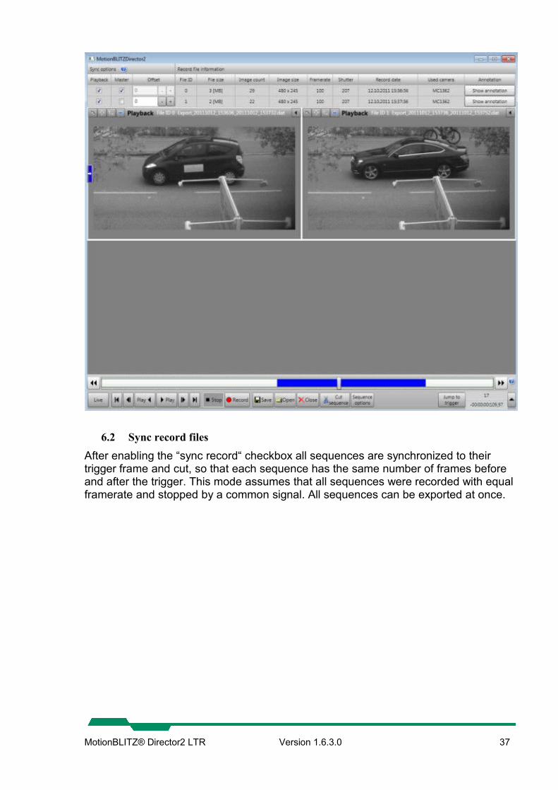
6.2 Sync record files
After enabling the “sync record“ checkbox all sequences are synchronized to their trigger frame and cut, so that each sequence has the same number of frames before and after the trigger. This mode assumes that all sequences were recorded with equal framerate and stopped by a common signal. All sequences can be exported at once.
MotionBLITZ® Director2 LTR Version 1.6.3.0 37

7 IRIG-B time code receiver (Optional)
If the LTR has the optional IRIG feature each frame is marked with a synchronized timestamp. The time information is written into the first line of each frame and can be displayed in the info line.The resolution of the timestamp is 100µs. The info line shows the UTC timestamp and the difference to the trigger frame which is computed from the UTC timestamp for each frame.Format of the timestamp: JJJJ-MM-TT hh:mm:ss.fe.g. 2011-10-27 07:16:48.713.86 Format of the computed difference to the trigger frame: hh:mm:ss.fe.g. 00:00:20:371.95
The used time code receiver card is a Meinberg TCR170PEX. The card can be freely adjusted using Meinbergs control tool. For more information, see manual for TCR170PEX.
Please make sure that the signal from the time code generator is valid and synchronized. If the receiver card is not synchronized “(Sync?)“ is appended
to the timestamp.
The timestamp is taken on FVAL. This is the point of time when the exposure is finished and the transmission into the grabber starts. This means that the
exposure time has an influence on the created timestamp.
MotionBLITZ® Director2 LTR Version 1.6.3.0 38

8 I/O Board
The IO board has eight inputs which can be used by the software.
MotionBLITZ® Director2 LTR Version 1.6.3.0 39

8.1 Pinning of the 15 pin D-Sub connector
The parallel I/O signals are accessible through 15 pin female D-Sub connectors on the rear side. Both connectors are identical therefore this manual describes only one connector.
15 pin D-Sub connectorfemale on rear side of PC
Name Type Signal Comment Pin Out0 OC Output 1 1VCC Power out +5V supply Power supply from PC 9Out1 OC Output 2 2Rx Common
pin of res. networks
+V in Input to resistor network 10
Out2 OC Output 3 3K0 In Cathode bit 0 11Out3 OC Output 4 4K1 In Cathode bit 1 12CE Common
Emitter 5
K2 In Cathode bit 2 13GND/A0
GND/In
Logic GND/Anode bit 0
Depends on jumper J1/J2 6
K3 In Cathode bit 3 14A1 In Anode bit 1 7A3 In Anode bit 3 15A2 In Anode bit 2 8 OC = open collector of the optocoupler - CE = common emitter of the optocoupler. The anodes of the input LED’s are connected to a replaceable single-in-line resistor of 330 ohms (RSB). The common pin of the single-in-line resistor is connected to pin 10 of the 15pin D-Sub connector on the rear side. The output optocoupler is a Darlington type. The collectors are connected with a replaceable single-in-line resistor RSC (see table 1) 4.7KOhm/0.25W. See technical data of the optocoupler and the schematic on the following pages. The cathodes of the input-LED’s are connected to a resistor array RSA (see table 1). This resistor array is replaceable. The common pin of the resistors is pin 5 at 15-pin D-connector.
Part name / ValueChannel Remark RSA RSB RSC
0 RS4 / n. p. RS5 / 330 RS3 / 4.7k1 RS9 / n. p. RS10 / 330 RS8 / 4.7k
n. p. : not populated Table 1: Resistor array names
MotionBLITZ® Director2 LTR Version 1.6.3.0 40

8.2 Example schematics
8.2.1 Connection of one input8.2.1.1 Light barrier with NPN transistor
Resistor RX must be built into the connection between the light barrier and the parallel plug.The value is calculated as follows: RX [] = ((Supply voltage – 2) [V]/ 0.015 [A] ) – RB []RX [] 0 [] RX = 0 for 5 V supplyRX = 330 / 0.25 W for 12 V supplyRX = 1.2 k / 0.25 W for 24 V supply
MotionBLITZ® Director2 LTR Version 1.6.3.0 41

8.2.1.2 Light barrier with PNP transistor
Resistor RX must be built into the connection between the light barrier and the parallel plug.The value is calculated as follows:
RX [] = ((Supply voltage – 2) [V]/ 0.015 [A] ) – RB []
RX [] 0 []
RX = 0 for 5 V supplyRX = 330 / 0.25 W for 12 V supplyRX = 1.2 k / 0.25 W for 24 V supply
MotionBLITZ® Director2 LTR Version 1.6.3.0 42

8.2.2 Connecting more InputsThe other inputs may also be used as free programmable input lines.In the following schematics, the external device supplies 24 Volts.
8.2.2.1 Opto inputs - connected to relays or NPN transistorsThe first example connects the positive pin of external 24V with pin 10 of the 15pin D-Sub connector. The inputs 11, 12, 13 and 14 are connected via a series resistor 1,2KOhm 1/3W and an external contact or a NPN transistor to the negative pin of the external 24V.In this example, the resistor network RSB must be present while RSA (see table 1) must be omitted.
M716 external connection M716 external connection8.2.2.2 Opto inputs - connected to relays or PNP transistors
In the second example, the negative pin of an external 24V is connected to pin 5 of the 15-pin D-Sub connector. The inputs 6, 7, 8, and 15 are connected via a series-resistor 1,2KOhm 1/3W to a switch or a PNP transistor with the positive pin of the external 24V. The resistor-network RSB must be plugged into the position of resistor-network RSA (see table 1). Pins 1 and 2 of the solder jumper must be closed.
M716 external connection M716 external connection
MotionBLITZ® Director2 LTR Version 1.6.3.0 43

8.2.2.3 Opto inputs - random accessThe third example separates each input from the other. RSA and RSB must be omitted. Pins 1 and 2 of the solder jumper must be closed.
M716 external connection8.2.3 Connection to the outputs
The output optocoupler is a Darlington type. The collectors are connected with a replaceable single-in-line resistor RSC (see table 1) 4.7KOhm/0.25W.This example shows the connection of the outputs with LED’s on an external 24V power supply.
M716 external connection
MotionBLITZ® Director2 LTR Version 1.6.3.0 44

8.3 Schematic of the Opto I/O Board
Part name / ValueChannel Remark RSA RSB RSC Jumper
0 RS4 / n. p. RS5 / 330 RS3 / 4.7k J11 RS9 / n. p. RS10 / 330 RS8 / 4.7k J2
n. p. : not populated
MotionBLITZ® Director2 LTR Version 1.6.3.0 45