monitoring and control network (mcn™) comparator...
TRANSCRIPT

68-11135-100
Monitoring and Control Network (MCN™)Comparator Display System
System Planner
S2-60616-100
August, 1996

MCN Comparator Display System Planner
Disclaimer NoteThe information within this document has been checked and is believed to be reliable. However, no responsibility isassumed for any inaccuracies. Furthermore, CTI Products, Inc. reserves the right to make changes to any products hereinto improve reliability, function, or design. CTI Products, Inc. assumes any liability arising out of the application or use ofany product, recommendation or circuit described herein: neither does it convey any license under their patents or right ofothers.
Computer Software CopyrightsThis manual describes products which include copyrighted CTI Products, Inc. computer programs on disk and in semiconductormemory. CTI Products, Inc. reserves all rights for these programs, including the exclusive right to copy or reproduce thecopyrighted computer programs in any form.
No copyrighted computer program contained in products described in this manual may be copied, reproduced, decompiled,disassembled, or reversed engineered in any manner without express written permission of CTI Products, Inc. The purchase ofproducts from CTI Products, Inc. shall not be deemed to grant either directly or by implication, estoppel, or otherwise, any licenseunder the copyrights, patents, or patent applications of CTI Products, Inc., except for the normal non-exclusive, royalty fee licenseto use that arises by operation of law in the sale of the product.
TrademarksMCN is a trademark of CTI Products, Inc.ASTRO-TAC, DIGITAC, and Spectra-TAC are trademarks of Motorola.Other trademarks referenced are properties of their respective owners.
1211 West Sharon RoadCincinnati, OH 45240
(513) 595-5900
No part of this manual may be reproduced or transmitted in any form or by any means, electronic or mechanical,including photocopying and recording, for any purpose without the written permission of or CTI Products, Inc.
Copyright 1995-1996, CTI Products, Inc. All rights reserved.

Table of Contents
MCN Comparator Display System Planner Page i
1. INTRODUCTION AND MANUAL OVERVIEW.......................................................................................................1
1.1 MCN SYSTEM OVERVIEW ...............................................................................................................................................2
2. SYSTEM OPERATION.................................................................................................................................................3
2.1 PC-BASED SYSTEM FOR DIGITAC, SPECTRA-TAC, OR ERICSSON COMPARATORS / VOTERS ...........................................32.1.1 System Description...................................................................................................................................................32.1.2 MCN Remote Comparator Display PC Software Operation....................................................................................42.1.3 System Hardware Requirements ..............................................................................................................................42.1.4 PC Display Screen Layout .......................................................................................................................................52.1.5 Controlling Receivers ..............................................................................................................................................62.1.6 Error Logging ..........................................................................................................................................................62.1.7 MCN RCD Software Configuration .........................................................................................................................6
2.2 CONSOLE-BASED SYSTEM WITH ASTRO-TAC COMPARATOR ........................................................................................72.2.1 System Description...................................................................................................................................................72.2.2 IIB Module Connections to a Console .....................................................................................................................8
3. SYSTEM COMPONENTS AND SPECIFICATIONS ................................................................................................9
3.1 MODULE TYPES ...............................................................................................................................................................93.1.1 Comparator Input Output Modules (CIBs and AIBs) ..............................................................................................93.1.2 User Interface Modules (HIBs and IIBs) .................................................................................................................93.1.3 Transmitter Steering Interface Modules (TIBs) .....................................................................................................103.1.4 System Extension Modules (EXBs).........................................................................................................................103.1.5 Router and Repeater Modules................................................................................................................................10
3.2 COMMON SPECIFICATIONS FOR MODULES .....................................................................................................................113.3 ASTRO-TAC COMPARATOR INTERFACE MODULE (AIB) .............................................................................................113.4 COMPARATOR INTERFACE MODULE (CIB) ....................................................................................................................123.5 HOST COMPUTER INTERFACE MODULE (HIB) AND MCN RCD SOFTWARE ..................................................................123.6 INPUT/OUTPUT INTERFACE MODULE (IIB) ....................................................................................................................133.7 TRANSMITTER STEERING INTERFACE MODULE (TIB)....................................................................................................143.8 EXB SYSTEM EXTENDER MODULE ...............................................................................................................................15
4. SYSTEM INSTALLATION OPTIONS......................................................................................................................16
4.1 MOUNTING OPTIONS......................................................................................................................................................164.1.1 Rack Mounting .......................................................................................................................................................164.1.2 DIGITAC Bracket and Cable Rear Mount.............................................................................................................174.1.3 Wall Mounting .......................................................................................................................................................18
4.2 PARALLEL I/O CABLING.................................................................................................................................................184.2.1 DIGITAC Comparators Cabling with DIGITAC Bracket and Cabling .................................................................184.2.2 DIGITAC Comparators Cabling with DIGITAC Rack or Wall Mount ..................................................................184.2.3 Spectra-TAC and TAC Comparators and Ericsson Analog Voters........................................................................194.2.4 IIB I/O Modules: ....................................................................................................................................................19
4.3 NETWORK CABLING.......................................................................................................................................................194.4 POWER REQUIREMENTS / POWER SUPPLY SPECIFICATIONS............................................................................................21
5. DESIGNING AND ORDERING A SYSTEM ............................................................................................................23
5.1 DESIGNING AN MCN SYSTEM ........................................................................................................................................245.1.1 Network Planning / Equipment Location...............................................................................................................245.1.2 AIB Considerations ................................................................................................................................................245.1.3 IIB Considerations .................................................................................................................................................245.1.4 CIB Considerations................................................................................................................................................24
5.2 MCN SYSTEM COMPONENTS.........................................................................................................................................265.3 CUSTOM SYSTEM CONFIGURATION WORKSHEET...........................................................................................................28

Table of Contents
Page ii MCN Comparator Display System Planner
6. APPENDIX B AVAILABLE DOCUMENTS............................................................................................................ 33
7. APPENDIX C SYSTEM EXAMPLES....................................................................................................................... 34
7.1 EXAMPLE 1 - PC BASED SYSTEM FOR DIGITAC COMPARATOR-- 8 RECEIVERS.......................................................... 347.2 EXAMPLE 2 - PC BASED DIAL-UP SYSTEM FOR SPECTRA-TAC OR ERICSSON COMPARATOR-- 12 RECEIVERS ............. 357.3 EXAMPLE 3 - EXTENDED DISTANCE SPECTRA-TAC OR ERICSSON COMPARATOR CONNECTED TO A CONSOLE -- 16RECEIVERS.......................................................................................................................................................................... 367.4 EXAMPLE 4 - 24 RECEIVERS WITH MULTIPLE OPERATOR POSITIONS ............................................................................ 387.5 EXAMPLE 5 - ASTRO-TAC COMPARATOR WITH 8 RECEIVERS DISPLAYED ON A CONSOLE......................................... 407.6 EXAMPLE 6 - MULTIPLE REMOTE PCS USING EXB SYSTEM EXTENDERS.................................................................... 417.7 EXAMPLE 7 - MULTI-SITE COMPARATOR NETWORKS ZONE & MASTER/SLAVE (SUB) COMPARATORS ....................... 427.8 EXAMPLE 8 - CONTROLLING TRANSMITTER STEERING SYSTEMS USING TIB MODULES ............................................... 43
8. APPENDIX D MODULE ADDRESSING AND RECEIVER BANKS ................................................................... 44
8.1 MODULE ADDRESSING.................................................................................................................................................. 448.2 RECEIVER BANKS ......................................................................................................................................................... 45
9. APPENDIX E SYSTEM LIMITATIONS WHEN USING HIB AND IIB MODULES TOGETHER ................. 46
10. APPENDIX F WARRANTY .................................................................................................................................... 47
11. APPENDIX G CUSTOMER SUPPORT ................................................................................................................. 48
12. APPENDIX H GLOSSARY...................................................................................................................................... 49
LIST OF FIGURESFIGURE 1 - BASIC MCN SYSTEM .......................................................................................................................................... 2FIGURE 2 - SYSTEM OPERATION EXAMPLE ........................................................................................................................... 3FIGURE 3 - RECEIVER ACTIVITY ON AN RCD SCREEN .......................................................................................................... 5FIGURE 4 - 8 ASTRO-TAC RECEIVERS WITH CONSOLE DISPLAY ........................................................................................ 7FIGURE 5 - CONSOLE ELECTRONICS INTERFACE ................................................................................................................... 8FIGURE 6 - MCN QUAD RACK MOUNT............................................................................................................................... 16FIGURE 7 - RACK MOUNTING - FRONT AND SIDE VIEW....................................................................................................... 16FIGURE 8 - DIGITAC BRACKET AND RIBBON CABLE............................................................................................................ 17FIGURE 9 - WALL MOUNTING ............................................................................................................................................. 18FIGURE 10 - MCN CABLE PINOUT ...................................................................................................................................... 20FIGURE 11 - MCN NETWORK TERMINATOR ....................................................................................................................... 20FIGURE 12 - DC POWER CHAINING..................................................................................................................................... 21FIGURE 13 - POWER DISTRIBUTION EXAMPLE..................................................................................................................... 22FIGURE 14 - 8 DIGITAC RECEIVERS WITH PC DISPLAY ....................................................................................................... 34FIGURE 15 DIAL-UP DISPLAY FOR UP TO 16 RECEIVERS ..................................................................................................... 35FIGURE 16 - 16 RECEIVERS WITH CONSOLE DISPLAY.......................................................................................................... 36FIGURE 17 - 24 RECEIVERS WITH MULTIPLE OPERATOR CONSOLE AND PC POSITIONS ...................................................... 38FIGURE 18 - 8 ASTRO-TAC RECEIVERS WITH CONSOLE DISPLAY .................................................................................... 40FIGURE 19 MULTIPLE LOCAL PC DISPLAYS WITH REMOTE COMPARATORS USING EXB MODULES.................................... 41FIGURE 20 MULTIPLE REMOTE COMPARATOR SITES COMBINED WITH EXB MODULES ...................................................... 42FIGURE 21 CONTROLLING A TRANSMITTER STEERING SYSTEM WITH A TIB MODULE ....................................................... 43FIGURE 22 - GROUP AND MODULE SWITCHES..................................................................................................................... 44FIGURE 23 - MCN BANK CONFIGURATION EXAMPLE ......................................................................................................... 45

Section 1. Introduction and Manual Overview
MCN Comparator Display System Planner Page 1
1. Introduction and Manual Overview
The Monitoring and Control Network (MCN™) Comparator Display system provides remotemonitoring and control for voting receiver systems. It extends the comparator status indicators fordisplay on a PC and allows an operator or technician to force-vote and disable receivers from a PC.With the MCN system you can control and display multiple comparators from a single point or multiplepoints. It works with DIGITAC, Spectra-TAC, TAC comparators and Ericsson / GE analog voters.
The MCN system can also be used to provide status and control input/output to a console for ASTRO-TAC systems. ASTRO-TAC systems with 8 or fewer receivers per channel can be monitored andcontrolled on a PC. This is a major convenience since ASTRO-TAC comparators do not have anyindication of active or voted receivers. The AIB ASTRO-TAC Interface Modules are availableexclusively through Motorola.
The MCN Comparator Display System is targeted for the following applications:• Systems which need comparator display for dispatchers• Systems that need remote comparator display and control for technicians• Critical comparator systems which require failure logging• Large comparator systems (wide area or large number of channels)• Ribbon Systems• Analog Trunking systems with voting receivers• ASTRO-TAC systems that require display of comparator status for a dispatcher or technician on a
PC or a console• Any voting system that needs rapid maintenance and diagnostics.
Typical customers are:• Public Safety Dispatch Centers• Police and Fire Departments• State Police systems• State and Local Governments• Turnpike systems• Transit authorities• Utilities• Federal Government systems• Forestry / Conservation
Features:• Remote display of comparator status (Vote, Receive, Disable, Fail)• Remote control of receivers (Force Vote, Disable)• Remote Comparator Display and Control on a PC• Intuitive operation• PC based system saves space over a comparable button and LED system• Can provide Input/Output signals for various button and LED or CRT consoles.• Error Logging for Receiver Failures on PC systems
Benefits:• Easy RF communications system troubleshooting• Remote disabling of noise-producing equipment• Automatic logging of RF system malfunctions• Quicker system maintenance• Lower system down time

Section 1. Introduction and Manual Overview
Page 2 MCN Comparator Display System Planner
1.1 MCN System Overview
Figure 1 shows a basic MCN comparator display system. The MCN system is made up of twomodules, a Comparator I/O Module and a User Interface Module. The Comparator I/O Moduleprovides the hardware interface to the comparator. The User Interface Module provides the mechanismfor the user to monitor and control the comparator.
CA-80018-100
USERINTERFACE INTERFACE
MODULE MODULE
COMPARATORCOMPARATOR
MCN NETWORKUSER
I/0
MCN SYSTEM
Figure 1 - Basic MCN System
The Comparator I/O Module and the User Interface Modules connect with a single cable between thenetwork ports of the modules, simplifying system installation. Standard systems can include up to 20Comparator I/O Modules in a single network segment. Larger comparator display systems consistingof multiple network segments tied together with routers/repeaters can be custom configured by CTIProducts, Inc.
Together, the Comparator I/O Module and the User Interface Module provide a simple, cost effectiveway to control your comparator system. Because of the MCN system’s modular design, yourcomparator display system can easily expand as your communications system grows.

Section 2. System Operation
MCN Comparator Display System Planner Page 3
2. System Operation
This section describes the basic operation of both Comparator I/O Modules and User InterfaceModules in a comparator display system. Two systems are described:
• A PC based system connected to three DIGITAC, Spectra-TAC, or Ericsson / GE comparators,and
• A console-based system connected to an ASTRO-TAC comparator.
In an MCN system, the Comparator I/O Module accepts VOTE, RECEIVE, DISABLE, and FAILreceiver status messages from the comparator and sends them to a User Interface Module over theMCN network. User Interface Modules then display the comparator status information on a console orPC.
Likewise, when a User Interface Module sends FORCE VOTE or DISABLE commands, theComparator I/O Module translates the commands and sends them to the comparator.
2.1 PC-Based System for Digitac, Spectra-TAC, or EricssonComparators / Voters
2.1.1 System DescriptionFigure 2 shows a small system made up of three Comparator I/O Modules (the CIBs) and one UserInterface Module (the HIB). The PC can monitor and control all three comparators from a singlescreen. When a receiver is force voted from the PC, a FORCE VOTE message is generated by theMCN RCD software and sent to the CIB that is controlling that particular receiver. When the CIBreceives the FORCE VOTE message, it will drive the receiver’s VOTE output line to signal thecomparator that the receiver is being force voted. A similar process occurs when a receiver is disabledfrom the PC.
Going the other direction, when the comparator detects that a receiver is active, it will drive the RXinput of the CIB. The CIB will then generate a RECEIVE message and send it to the HIB so that theactive receiver can be shown on the PC screen. A similar process occurs when the comparatorgenerates a Vote (driving the CIB’s VOTE input) or a Fail (driving the CIB’s FAIL input) signal.
COM 2
COM 1
CA-80041-100
2
COMPARATORS
CIB
CIB
CIB
T
HIBT
1
3
P/S
OUT
IN
IN
IN
IN
OUT
OUT
OUT
P/S
LOCAL PC
Figure 2 - System Operation Example(P/S = Power Supply, T = Network Terminator)

Section 2. System Operation
Page 4 MCN Comparator Display System Planner
2.1.2 MCN Remote Comparator Display PC Software OperationTwo programs make up the MCN RCD software package. They are:
• MCNCFG.EXE - the configuration program
• MCNRCD.EXE - the runtime Remote Comparator Display program.
The MCNCFG program is run by an engineer or technician to build the configuration files when thesystem is installed or changed. The MCN RCD program is run by a dispatcher or technician to displaythe status of the voting system.
The MCN RCD software allows the operator to see which receivers are receiving, voted, disabled,failed or in an error condition on the PC. It also allows the operator to monitor and disable receiverswith the Force Vote and Disable functions.
2.1.3 System Hardware RequirementsTwo components are required for the MCN RCD system.
1. Host Computer Interface Module (HIB)
2. A PC to run the MCN RCD software with the following minimum configuration:
• 25 MHz 386 PC (for 1-9 Comparator I/O Modules)
• 50 MHz 486 PC (for 10-20 Comparator I/O Modules)
• EGA or VGA adapter and monitor
• 2 MB RAM
• 10 MB free disk space
• Microsoft or Logitech mouse
• one open serial port capable of 38.4k baud
• MS-DOS 5.0 or higher

Section 2. System Operation
MCN Comparator Display System Planner Page 5
2.1.4 PC Display Screen LayoutA typical receiver screen is shown below:
Figure 3 - Receiver Activity on an RCD ScreenThe Receiver Display Screen has the following items:• Menu Bar Located at the top left of the screen
• Screen Name Located at the top center of the screen
• Channel Titles Highlighted areas that extend across the receiverName column and the Receiver Indicator Column
• Receiver Names Located on the left side of the four columns in thebody of the screen
• Receiver Indicators Located to the right of the Receiver Names
• Error Status Line Present on the bottom line of the screen when anerror has occurred and the “Show Errors OnScreen” option is enabled.
The Receiver Indicators display the status of the receivers. The following status indications can bedisplayed:
Status Indicator Background color Text ColorNo Activity BlueVote Vote Green WhiteReceiving Rx Lt Gray Dark GrayDisabled Dis Yellow BlackFailed Fail Red WhiteError Err Brown Yellow
The status text and colors can be custom configured at time of installation.
Section 2. System Operation
Page 6 MCN Comparator Display System Planner
2.1.5 Controlling ReceiversYou can use the MCN RCD program to control the receiver operation at your remote comparator. Youcan manually FORCE VOTE a receiver from the PC and listen to its audio quality over your system.You can also DISABLE a receiver that is defective or has a bad phone line. When the receiver orphone line is repaired, you can re-enable the receiver from the PC. Receivers can be controlled witheither the mouse or keyboard.
2.1.6 Error LoggingThe MCN RCD program can log system errors on a PC. The PC will log whenever a receiver fails orbecomes disabled. It will also log when the receiver returns to a normal condition. Logging entriesinclude a time and date stamp, the receiver status, the group, module, and receiver number, the receivername, and the comments for that receiver. The log entries are stored in an ASCII text format on thedisk. The error logging feature is available only when the PC is connected to the MCN system. Noerror information is logged when the PC is off-line.
2.1.7 MCN RCD Software ConfigurationThe MCN Remote Comparator Display software includes a configuration program, MCNCFG.EXE,which allows you to custom-configure your system. The configuration is a two-step process:
1. For each Group of 16 comparator I/O modules (CIBs and AIBs), enter the receiver names, channelnames, and comments for each receiver.
2. Build the screen by entering channel titles and then by placing the receivers that were previouslydefined using a “point and shoot” selection method.
An MCN Group Configuration file (.GCF extension) contains all of the receiver information for aparticular set of MCN Comparator I/O Modules, all addressed into a single MCN Group.
MCN Screen Files (.MSF extension) contain a list of receivers to be displayed on the current CRTscreen and where they will appear on the screen. One MCN Screen File supports four different GroupConfiguration Files so that receivers from four different MCN Groups can be monitored and controlledfrom the same screen.
Up to 88 receivers can appear on the PC display. For many systems this will allow an operator to viewall of the receivers in a voting receiver system. On larger systems as many as 50 screens can be createdto display a system’s receivers.

Section 2. System Operation
MCN Comparator Display System Planner Page 7
2.2 Console-Based System with ASTRO-TAC Comparator
2.2.1 System DescriptionThe following diagram shows a simple system for ASTRO-TAC comparator display and control on aconsole. The AIB ASTRO-TAC Interface Module is connected to the comparator via a serial cable.The IIB I/O Interface Module is connected to 16-I/O boards in a Central Electronics Bank (CEB).
The status can be displayed on a console with parallel I/O lines for Vote, Receive, Disable, and Failindicators and switches. The console is configured just as if it is connected to a standard analogcomparator such as a DIGITAC or Spectra-TAC comparator. In this configuration, the comparatordisplay and control will be running through the console electronics.
CA-80016-100
IIBCONSOLE
ELECTRONICS
COMPARATORASTROTAC
AIBOUT
P/S
IN
CONSOLE
IN
OUT
T
T
Figure 4 - 8 ASTRO-TAC Receivers with Console Display
(P/S = Power Supply, T = Network Terminator)

Section 2. System Operation
Page 8 MCN Comparator Display System Planner
2.2.2 IIB Module Connections to a ConsoleIn a console-based system, the VOTE and DISABLE control lines that connect to the I/O lines of theconsole are actually bi-directional signals. Figure 5 shows the interface between the consoleelectronics and the IIB’s J1 connector.
CA-80049-100
+V
+V
MOMENTARY
+V
+V
LATCHING
CONSOLE ELECTRONICS IIB J1
VOTE
FAIL
RX
DISABLE
Figure 5 - Console Electronics Interface

Section 3 System Components and Specifications
MCN Comparator Display System Planner Page 9
3. System Components and Specifications
3.1 Module TypesThe MCN Module types consist of five classes or types of modules:• Comparator Input/Output Modules• User Interface Modules.• Transmitter Steering Interface Modules• System Extender Modules• Router and Repeater Modules
3.1.1 Comparator Input Output Modules (CIBs and AIBs)Comparator I/O Modules provide the physical connection between the comparator and the MCNnetwork. Depending on the features provided by the comparator, the connection to the comparator maybe discrete I/O points that are hard wired to the comparator, or a simple RS-232 cable connected to acommunications port on the comparator.
The following are the MCN Comparator I/O Modules:
• Comparator Interface Module (CIB)
• ASTRO-TAC Comparator Interface Module (AIB) (available exclusively throughMotorola)
Each module is briefly described in its own section. For more information about features specific to anindividual module, refer to its hardware reference manual.
3.1.2 User Interface Modules (HIBs and IIBs)An MCN User Interface Module connects the MCN network to various User Interface devices. Theuser interface may be simple lights and push buttons, such as a console, or the user interface may be aprogram running on a PC to monitor and control the comparator.
The following are CTI Products’ MCN User Interface Modules:
• Host Computer Interface Module (HIB) for PC interface (serial)
• Input/Output Interface Module (IIB) for console interface (parallel)
Each module is briefly described in its own section. For more information about features specific to anindividual module, refer to its hardware reference manual.

Section 3 System Components and Specifications
Page 10 MCN Comparator Display System Planner
3.1.3 Transmitter Steering Interface Modules (TIBs)The Transmitter Steering Interface Modules (TIBs) work in conjunction with the CIB comparatorInterface Modules and external Transmitter Steering equipment, such as the TSAM TransmitterSteering Unit from CTI Products. This interface provides monitor and control of transmitter sites froma PC with a HIB as the Operator Interface Module. The CIB is the only Comparator I/O Module thatoperates with the TIB and the HIB is the only User Interface Module that operates with a TIB.
The TIB is used in systems that have multiple transmitters, with each transmitter associated with one ormore receivers and that use the TSAM to provide steering for the transmitter sites. The TIB willtranslate a FORCE VOTE command for a particular receiver into a FORCE TX command thatcommands the TSAM to steer to the transmitter associated with the receiver being FORCE VOTED.The TIB can also monitor the TSAM for the active transmitter site for display on a PC.
3.1.4 System Extension Modules (EXBs)The EXB modules are used in pairs to connect two MCN networks together or to extend the length ofan MCN network beyond 4000 feet. Typical applications include:
• Extending MCN Networks over phone lines
• Display and control multiple remote comparator locations at a central location
• Connects multiple local PC displays to a remote MCN network using 1 phone line
• Zone Comparators
• Master/Slave Comparators (Sub-Comparators)
• State-Wide / Regional / City-Wide voting systems
The EXB System Extender Modules use any analog or digitized analog channel (including standard 2-wire or 4-wire leased lines, or microwave channels) which is capable of carrying V.32 terbo standardmodem signaling,. Data transfer between distant networks is "live", delayed only by the transit timethrough the EXB modules and the data rate across the modem link.
3.1.5 Router and Repeater ModulesRouter and repeater modules are available on special order to extend the MCN network in the samebuilding. They can also extend the network capacity to greater than 64 modules or 20 ComparatorInterface Modules. The implementation of systems with these modules is customer-specific. CTIProducts applications engineers will be happy to assist you in designing a custom system that extendspast the normal limits of the MCN network.

Section 3 System Components and Specifications
MCN Comparator Display System Planner Page 11
3.2 Common Specifications for ModulesAll modules are housed in similar metal enclosures. They all have similar environmental and powerrequirements. The common specifications are listed in Table 1. Specifications for features specific toa module or specifications that differ from these common specifications are listed in that module’ssection of this manual.
Size 5.5” x 4.2” x 1.5”(140 x 107 x 38 mm)
Weight 16 oz (455 gm)Temperature 0 - 50 ºCHumidity 10 - 95% non-condensingModule Power 10 - 32 Vdc / 2 Watts nominalNetwork Connector (2) RJ-45 (1 in, 1 out)
Includes network connections andpower distribution
Safety Approvals UL 1950CSA 1950EN 60950-1992
Emissions Compliance FCC Part 15, Class ADOC Class AEN55022 Class A
Susceptibility Compliance IEC 801-2IEC 801-3IEC 801-4EN50082-1
Table 1 - Common Module Specifications
3.3 ASTRO-TAC Comparator Interface Module (AIB)The AIB connects Motorola’s ASTRO-TAC comparator to the MCN network. Features of the AIBmodule include:
• Serial communication cable connects the AIB to the ASTRO-TAC comparator.
• Support for up to 16 receivers per AIB.
• Provides VOTE, RECEIVE, DISABLE, and FAIL status for each receiver to an MCNUser Interface Module.
• Allows a User Interface Module to FORCE VOTE or DISABLE any receiver.
Number of Receivers Supported 16Comparator Connector 9 pin D-SUB, femaleASTRO-TAC Interface HDLC Synchronous Serial
9600 BaudASTRO-TAC Firmware Version System Release 1.7 or later
Table 2 - AIB Module Specifications

Section 3 System Components and Specifications
Page 12 MCN Comparator Display System Planner
3.4 Comparator Interface Module (CIB)The CIB connects various types of comparators with parallel I/O facilities to the MCN network.Features of the CIB module include:
• Parallel bi-directional I/O line connections between the CIB and a parallel I/Ocomparator, including Motorola DIGITAC, Spectra TAC, TAC, and Ericsson / GEanalog comparators.
• Support for up to 8 receivers per module.
• Provides VOTE, RECEIVE, DISABLE, and FAIL status for each receiver to an MCNUser Interface Module.
• Allows a User Interface Module to FORCE VOTE or DISABLE any receiver.
• The CIB can be connected to more than one comparator (with total support for 8receivers) as long as the comparators are of the same type.
Option switches on the front panel of the CIB configure the type of comparator being used. Refer tothe CIB hardware reference manual for a description of the CIB’s option switches.
Number of Receivers Supported 8Open Circuit Voltage (all I/O pins) jumper E1B removed jumper E1B installed
+13.8 Vdc nominal (Standard) +5 Vdc nominal (Logic Levels)
Inputs per Receiver active low, pull-up to +5 or +13.8 Vdc
Vote, Receive, Disable and Fail
Input Voltage (Input and In/Out pins) -0.6 to 30 Vdc max.Input Current (Input and In/Out pins): jumper E1B removed (Vin = 0 Vdc) jumper E1B installed (Vin = 0 Vdc)
-720 µA max. (source)-270 µA max. (source)
Outputs per Receiver (active low) Force Vote and DisableOutput Saturation Voltage (Outputs and In/Outpins) with Output Current = 100 mA
550 mV max.
Output Pin Current (Outputs and In/Out pins) 150 mA max. per pin (sink)100 mA max. per pin if alloutputs are ON
Input/Output Connection 50 pin Telco style
Table 3 - CIB Module Specifications
3.5 Host Computer Interface Module (HIB) and MCN RCDSoftwareThe HIB provides a serial interface to a PC and works with the Monitoring and Control NetworkRemote Comparator Display (MCN RCD) software to provide comparator monitoring and control.Features of the HIB module / MCN RCD software combination include:
• Easy to use software for visual indication of voting system status
• Monitors up to 4 groups of 16 comparator I/O modules simultaneously (512 receivers).
• Displays up to 88 receivers viewable on a single screen.
• Configurable receiver names and screen positions.
• Displays VOTE, RECEIVE, DISABLE and FAIL information for each receiver on thescreen.

Section 3 System Components and Specifications
MCN Comparator Display System Planner Page 13
• FORCE VOTE and DISABLE switch functions are controlled with either a mouse orkeyboard.
• Allows logging (to the screen and/or to a disk file) of receivers that fail or becomedisabled. Logging may be enabled or disabled by the operator.
• Modem support allows remote monitoring and control.
Because the module can be used with modems for remote operation, a technician no longer has totravel to the comparator site to diagnose system problems since he can monitor and control thecomparator from a properly equipped PC in their shop.
PC Connector 9 pin D-SUB, female, DCEBaud Rates Supported 9600, 14.4K, 19.2K, 38.4K (38.4K Default)
Table 4 - HIB Module Specifications
3.6 Input/Output Interface Module (IIB)The IIB provides discrete, parallel Input/Output points for monitoring and control of comparators. IIBoutputs can be connected to LEDs for viewing comparator status and inputs can be connected toswitches for control of comparator functions. Features of the IIB include:
• Support for up to 8 receivers.
• Status Outputs for each receiver which includes VOTE, RECEIVE, DISABLE, and FAIL.
• Control Inputs for each receiver include FORCE VOTE and DISABLE.
• Link Fail output which indicates a failed serial link with the ASTROTAC comparator.This output takes up one receiver output.
Number of Receivers Supported 8 (Link Fail feature disabled)7 (Link Fail feature enabled)
Open Circuit Voltage (all I/O pins) jumper E1B removed jumper E1B installed
+13.8 Vdc nominal (Standard) +5 Vdc nominal (Logic Levels)
Inputs per Receiver active low, pull-up to +5 or +13.8 Vdc
Force Vote, Disable
Input Voltage (Input and In/Out pins) -0.6 to 30 Vdc (max.)Input Current (Input and In/Out pins): jumper E1B removed (Vin = 0 Vdc) jumper E1B installed (Vin = 0 Vdc)
-720 µA max. (source)-270 µA max. (source)
Outputs per Receiver (active low) Vote, Receive, Disable, FailOutput Saturation Voltage (Outputs and In/Outpins) with Output Current = 100 mA
550 mV
Output Pin Current (Outputs and In/Out pins) 150 mA max. per pin (sink)100 mA max. per pin if all outputs areON.
Input/Output Connection 50 pin Telco style
Table 5 - IIB Module Specifications

Section 3 System Components and Specifications
Page 14 MCN Comparator Display System Planner
3.7 Transmitter Steering Interface Module (TIB)The Transmitter Steering Interface Modules (TIBs) work in conjunction with the CIB comparatorInterface Modules and external Transmitter Steering equipment, such as the TSAM TransmitterSteering Unit from CTI Products.
When a receiver is FORCE VOTED from the PC, the HIB sends a FORCE VOTE command to theCIB, the TIB that is associated with that CIB also receives the command and activates the TX Selectline for the specified receiver/transmitter. The TIB then activates the Force Select output line forapproximately 100 milliseconds. After this 100 milliseconds, the TX Select lines and the Force Selectline are deactivated so that the TIB can resume monitoring the transmitter status.
The TIB monitors the TSAM’s 8 TX Select lines to determine which transmitter is currently active.Whenever the TSAM steers to a transmitter, the TSAM updates the TX Select lines to indicate thecurrently active transmitter. The TIB sends the status information to a HIB over the MCN network sothat the transmitter status can be displayed on the PC.
Number of Transmitters Supported 8Open Circuit Voltage (all I/O pins) jumper E1B removed jumper E1B installed
+13.8 Vdc nominal +5 Vdc nominal
Inputs per Transmitter active low, pull-up to +5 or +13.8 Vdc
TX Select In
Input Voltage (Input and In/Out pins) -0.6 to 30 Vdc maxInput Current (Input and In/Out pins): jumper E1B removed (Vin = 0 Vdc) jumper E1B installed (Vin = 0 Vdc)
-720 µA max (source)-270 µA max (source)
Outputs per Transmitter (active low) TX Select OutControl Outputs (active low) Force SelectOutput Saturation Voltage (Outputs and In/Outpins) with Iout = 100 mA
550 mV max.
Output Pin Current (Outputs and In/Out pins) 150 mA max per pin (sink)100 mA max per pin if all output areON
Maximum Power Dissipation 2 WattsInput/Output Connection 50 pin Telco style
Table 6 - TIB Module Specifications

Section 3 System Components and Specifications
MCN Comparator Display System Planner Page 15
3.8 EXB System Extender ModuleThe EXB modules are used in pairs to connect two MCN networks together or to extend the length ofan MCN network beyond 4000 feet. One side of each EXB module connects to the MCN network.The other side connects to a 2-wire or 4-wire leased telephone line or analog microwave channel.
Power: 10 to 30 VDC 5 watts max.(Counts as 2 MCN standard loads)
Size: 7.5" D x 5.6" W x 1.6" H(MCN “B” size module)
Mounting: Desktop with integral non-slip feetOptional Wall Mount BracketOptional 19" rack mounts (1 Rack Unit high)
Temperature: 0-60°CHumidity: 10-95% non-condensingSafety Listings: UL1459, CSA C22.2, EC EN60950Telco Approvals FCC Part 68 (U.S.)
IC CS02 & CS03 (Canada)Telephone Line Levels: TX: -10 or -16 dBm
(Switch selectable)RX: -45 to -16 dBm
EMI: Complies with FCC part 15 Class AIndustry Canada (IC) Class AEN55022 Class A (European Union)
EMC: EN50082-1 (European Union)European: Carries the CE MarkModem: Internal V.32 terbo 19.2 Kbps, 2/4 wire leased line
(Switch selectable)Simultaneous Voice plus Data
MCN Network Standard 78 Kb or High-speed 1.25 Mb networkmodels available
Table 7 - EXB Module Specifications

Section 4. System Installation Options
Page 16 MCN Comparator Display System Planner
4. System Installation Options
4.1 Mounting OptionsEIA 19” rack mount, DIGITAC bracket and cable rear mount, and Wall mount kits are available forMCN modules. These kits are described below.
4.1.1 Rack MountingThe quad rack mount option provides a 19” rack mounting bracket that supports four MCN size Amodules. It requires 1 Rack Unit (1.75”) of rack space. Similar rack mounts are available for (3) B sizemodules (3B rack) and (2) A size plus (1) Size B module (2A+B rack).
IN OUTNETWORK PWR ACTERR
DC IN
OPTION ARESET SVC
1 2 3 4 5 6 7 8ON
PRODUCTS, INC.
897 A
BC
D
EF012
34
5
6897 A
BC
D
EF01234
5
6897 A
BC
D
EF01234
5
6
RESET
DC IN
OPTION
IN OUTNETWORK
PRODUCTS, INC.
MODULEGROUP
1 2 3 4ON
PWR ACTERR
897 A
BC
D
EF012
34
5
6897 A
BC
D
EF012
34
5
6897 A
BC
D
EF01234
5
6
RESET
DC IN
OPTION
IN OUTNETWORK
PRODUCTS, INC.
MODULEGROUP
1 2 3 4ON
PWR ACTERR
897 ABC
D
EF012
34
5
6897 AB
CD
EF01234
5
6897 AB
CD
EF01234
5
6
RESET
DC IN
OPTION
IN OUTNETWORK
PRODUCTS, INC.
MODULEGROUP
1 2 3 4ON
PWR ACTERR
NETWORK IN NETWORK OUT
HIB CIB CIB CIB
P/SCA-80148-100
Figure 6 - MCN Quad Rack Mount
Figure 7 shows an exploded view of the rack mount installation. The top diagram shows the front viewof the bracket with one module installed. The bottom two diagrams show a side view of the moduleinstallation and bracket installation respectively.
CA-80021-100
IN OUTNETWORK PWR ACTERR
DC IN
OPTION ARESET SVC
1 2 3 4 5 6 7 8ON
FACEPLATE
SPACER
PRODUCTS, INC.
Figure 7 - Rack Mounting - Front and Side View

Section 4. System Installation Options
MCN Comparator Display System Planner Page 17
4.1.2 DIGITAC Bracket and Cable Rear MountThe DIGITAC rear mount bracket and cable provides a quick and easy way to mount the CIB andconnect it to the DIGITAC without extra cables and punch blocks. The CIB module I/O connector hasa pinout that matches the DIGITAC P805 connector. The rear mount includes a ribbon “T” connector.One connector plugs into P805, another connects to the CIB module, and a third is a female 50-pinconnector for external comparator I/O connections. The DIGITAC rear mount kit is shown below:
DIGITAC
CIB
CIB
DIGITAC
P805 P806
CIB DIGITAC MTG. BRKT.
25
50
1
26
2.18
1
MOUNTS WITH 4 SCREWSFEMALE CONNECTOR FOREXTERNAL CONNECTIONS
RIBBON CABLE
NOTE ADDITIONAL CLEARANCEREQUIRED BEHIND DIGITAC WHENINSTALLING CIB AND BRACKET.
CA-80149-100
NE
TW
OR
K
INN
ET
WO
RK
OU
T
P/S
Figure 8 - Digitac Bracket and Ribbon Cable

Section 4. System Installation Options
Page 18 MCN Comparator Display System Planner
4.1.3 Wall MountingThe wall mount option allows a module to be mounted to a flat surface. Each MCN module has twoscrew holes located on the bottom of the module. Simply attach the mounting plate to the bottom of themodule using these two screw holes and then screw this assembly to the wall. The module can bemounted in any orientation. Figure 9 shows an exploded view of the wall mount installation.
CA-80026-100
IN OUTNETWORK PWR ACTERR
DC IN
OPTION ARESET SVC
1 2 3 4 5 6 7 8ON
PRODUCTS, INC.
Figure 9 - Wall Mounting
4.2 Parallel I/O CablingParallel I/O cables are standard 25-pair cables and are used with CIB Comparator Interface Modulesand IIB I/O Interface Modules. Three versions are available, a 10 and 25 foot male to male cable forconnection to punch blocks, and a 25 foot male to blunt end cable for wiring directly to the back of aSpectra-TAC comparator or Ericsson / GE Analog Voter.
4.2.1 DIGITAC Comparators Cabling with DIGITAC Bracket and CablingFor CIBs connected to DIGITAC comparators using the DIGITAC Bracket and Cable, the CIBconnects to the DIGITAC through a ribbon cable and no extra parallel I/O cable is required. The cableand punch block that are normally ordered to connect to P805 on the DIGITAC comparator will insteadbe connected to the third connector on the ribbon cable.
If a cable and punch block weren’t ordered for the DIGITAC, you can order a male to male cable andpunch block.
4.2.2 DIGITAC Comparators Cabling with DIGITAC Rack or Wall MountFor CIB modules which mount using a rack mount or wall mount, you will need a parallel I/O cable.You can order either:• Male to male 25-pair cable for use with a dedicated punch block
• Male to blunt end 25-pair cable to punch down to an existing punch block.

Section 4. System Installation Options
MCN Comparator Display System Planner Page 19
4.2.3 Spectra-TAC and TAC Comparators and Ericsson Analog VotersThere are 3 general ways to connect to these types of comparators:
1. Male to male 25-pair cable to punch block with field wiring to back of comparator. This optionprovides the most flexibility, but it requires a punch block and a place to mount it.
2. Male to blunt end 25-pair cable wired directly to the back of the comparator card cage. Thismethod eliminates the need for a punch block and works well if the CIB modules and comparatorsare mounted close in the same rack so that you can disconnect the cable from the CIB module ifthe comparator card cage must be removed.
3. A short 25-pair pigtail cable with a female connector wired directly to the comparator card cage.A male to male 25-pair cable then connects the CIB to the pigtail. This method eliminates theneed for a punch block, but still allows the comparator card cage to be removed from the rack forservice, especially if the CIB module is mounted in a different equipment rack. Note that thefemale pigtail cable is field fabricated.
4.2.4 IIB I/O Modules:There are two parallel cabling options for IIB modules:• Male to Male 25-pair cable and punch block with cross-connect to the comparator interface punch
block(s) for the console module. This is the most flexible option, but it does require extra punchblocks and mounting space.
• Male to blunt end 25-pair cable, punched down to the existing punch block(s) for the console I/Omodule. This option is less expensive and takes up less space. In the case of the MotorolaCentracom series II consoles, one IIB module can connect to two comparator interfaces in theCEB. With this option, you will have to split the cable apart and connect to two punch blocks, orto both sides of a split punch block.
4.3 Network CablingMCN modules communicate over a network cable. Specifications for network cabling are thefollowing:• 4 pair level IV or V unshielded, 24 AWG, twisted pair cable (EIA/TIA 568B).
• Maximum of 64 modules can be connected together, with a limit of 20 Comparator I/O Modulesper network segment.
• Maximum cable length is 4000 feet.
• Straight through connections.

Section 4. System Installation Options
Page 20 MCN Comparator Display System Planner
One side of the network cable is shown below. This diagram details the pinout and twisted pairconfiguration of the cable.
CA-80042-100
123
78
TOP VIEWOF CONNECTOR
456
DATA +DATA -+POWER
NCNC
-POWER-POWER+POWER
Figure 10 - MCN Cable PinoutWhen cabling your system, daisy-chain the modules together and insert a network terminator into theunused port of the first module and the unused port of the last module in the chain. An example ofwhat the terminator looks like is shown in Figure 11.
Use of standard length cables from CTI Products is highly recommended to provide best systemperformance. Standard lengths are available up to 1000 feet. Standard lengths can be combined withcable couplers to create desired length cables. Custom lengths can also be ordered.
If you do provide your own cable, be sure it meets the specifications above. The system will not workwith ordinary telephone cable.
The MCN network cable is not rated for outdoor use. The MCN system is not rated for cablingrunning exposed outdoors, for example with overhead lines, due to possible lightning surges.
If you are providing your own cable for a run longer than 100 feet, a new power supply will be requiredat the far end. You may use 2-pair Level IV or Level V cable instead of 4-pair. In this instance,connect just the data pair (Pins 1 and 2).
CA-80025-100
100 ohm 1/8 WATTRESISTOR
Figure 11 - MCN Network Terminator

Section 4. System Installation Options
MCN Comparator Display System Planner Page 21
4.4 Power Requirements / Power Supply SpecificationsPower input for all MCN modules is 10 to 32 VDC, with most modules requiring 2 W nominal. ACpower supplies are available that provide 18 VDC at 800 mA. MCN systems have been fully tested forappropriate immunity to harmful electrical noise and electrical impulses when assembled with thesepower supplies. Operation with other, non-qualified power supplies could yield lower systemperformance and may void US, Canadian, or European emissions and susceptibility approvals.
The DC IN receptacle of all MCN modules can accept either polarity configuration from the inputpower plug.
The MCN system provides a unique way to distribute power to multiple modules from a single powersupply. The network cable used for module communication also contains power lines so that the powerfrom a power supply can be distributed along with the communication lines. The limits of this powerdistribution are the following:• A maximum of four modules can be powered from a single power supply.
• The maximum cable length between the modules that share a power supply is 100 feet.
To create this power distribution (refer to Figure 12), simply connect the power supply into your firstmodule. Then, connect the NETWORK OUT port of that module to the NETWORK IN port of thenext module. Continue connecting NETWORK OUT ports to NETWORK IN ports until all modulesare connected. If you need to add more power supplies to the system due to power distribution limits,simply connect another power supply into the DC IN port of a module. This new power supply thenprovides power for the module it is connected to as well as all modules from that module’s NETWORKOUT port or until another power supply is encountered.
CA-80027-100
IN OUTNETWORK PWR ACTERR
DC IN
OPTION ARESET SVC
1 2 3 4 5 6 7 8ON
IN OUTNETWORK PWR ACTERR
DC IN
OPTION ARESET SVC
1 2 3 4 5 6 7 8ON
TO NETWORK INOF NEXT MCN MODULE
TO DC POWER SUPPLY
PRODUCTS, INC. PRODUCTS, INC.
Figure 12 - DC Power Chaining

Section 4. System Installation Options
Page 22 MCN Comparator Display System Planner
In the example shown in Figure 13, two power supplies are required, even though there are only fourmodules in the system. The second supply is required because the network cable between the third andfourth modules is greater than the 100 foot cable length maximum for power distribution.
CA-80028-100
IN OUT DC IN IN OUT DC IN IN OUT DC IN IN OUT DC IN
>100'
T T DC POWERSUPPLY
DC POWERSUPPLY
Figure 13 - Power Distribution ExampleThe following specifications apply to the AC power supplies:
120 VAC U.S. / Canada Power Supply (81-10398)This module is a plug-in type Class-2 power supply with integral 120VAC power prongs. It includes amounting tab for use with the grounding screw in a standard 15A outlet.
AC Voltage: 120 VAC 60 Hz 15WBasic Dimensions when plugged into a walloutlet
2.85” Wide x 3.5” High x 2.25” Deep(73 x 89 x 57 mm)
Overall dimensions with mounting tab andclearance for DC cable
2.85” Wide x 5.5” High x 2.25” Deep(73 x 140 x 57 mm)
DC Cable Length (Approximate) 6’ (1.8m)Weight 1.75 Lbs
When planning the number of outlet strips needed for your system, please note that the 120 V PowerSupply will use one outlet and will cover up two additional outlets on close-spaced outlet strips. Planfor three outlets for every 120V Power Supply.
230 VAC European Power Supply (81-10728)This module is a desk-top type Class-2 power supply unit with an IEC connector for the 230VACpower input. The customer shall furnish the appropriate line cord for the destination country.
AC Voltage 230 VAC 50/ 60 Hz 15WBasic Dimensions 4.75” Long x 3.2” Wide x 2.65” High
(121 x 81 x 67 mm)Overall dimensions with clearance for AC cordand DC cable
9” Long x 3.2” Wide x 2.65” High(229 x 81 x 67 mm)
DC Cable Length (Approximate) 6’ (1.8m)

Section 5 Designing and Ordering a System
MCN Comparator Display System Planner Page 23
5. Designing and Ordering a System
The following procedures should be followed when designing and ordering an MCN system.
Step Operation1 Determine the type of comparator in the system: Spectra-TAC, DIGITAC
TAC, or ASTRO-TAC comparator or Ericsson / GE analog voters.2 Determine the total quantity of comparators in the system.3 Determine how many receivers are connected to each comparator.4 Determine the type and quantity of operator interface required (PC or
console based).5 For console-based systems, determine the number of I/O cards, operator
interface modules, and I/O programming options required. Order theseitems from your console vendor.
For instance, in Motorola Centracom Series II consoles, B1426 Modulesare required in the Central Electronics Bank (CEB) for every 4 receiversand B1439 Comparator Display Modules are required for button and LEDconsoles for every 4 receivers.
6 Follow the intructtions in the Designing an MCN system section.

Designing an MCN system
Page 24 MCN Comparator Display System Planner
5.1 Designing an MCN systemBefore designing an MCN system, follow steps 1-6 on page 23.
5.1.1 Network Planning / Equipment LocationTypically, comparator interfaces (CIBs and AIBs) will be mounted near the comparators, either in rackmounts or in DIGITAC Bracket and Cable Rear Mount.
For DIGITAC comparators, the DIGITAC Rear Mount is the preferred method to mount the CIBbecause it includes a ribbon cable for quick and easy connection. It also conserves rack space. Forother comparators, the Quad Rack Mount is preferred. It can mount (4) modules.
For Console Logic I/O, the IIBs will mount near the console electronics (CEB). This may be local tothe comparator and AIBs, in which case they can mount to the same rack mounts as the AIBs. Theymay also be located at an extended distance from the comparators. In which case, they can be rackmounted near the CEB and connected to the comparator interfaces via an extended length networkcable. These are called Extended IIBs in the ordering worksheet.
HIBs connected to modems will normally be mounted locally to the CIBs.
HIBs connected directly to PCs will mount close to their PCs and will connect to the comparatorinterfaces through an extended length network cable. Extended HIBs can be mounted with their ownrack mount, a wall mount, or placed in the bottom of a console enclosure without a mount.
5.1.2 AIB ConsiderationsAIB modules are ordered per ASTRO-TAC RF channel. Only one AIB module is used per ASTRO-TAC comparator, up to 13 receivers. Each channel will need its own AIB module. Remember that PCdisplay systems can only display and control the first 8 ports on an ASTRO-TAC comparator. AIBmodules are available exclusively through Motorola.
5.1.3 IIB ConsiderationsIIBs monitor and control ASTRO-TAC receiver ports in banks of 8. You will need 1 or 2 IIBs perAIB. Note that consoles and transmit-only base stations each take up a port. If you use the Link Failindicator option on the IIB, it will take up the highest receiver in the system (#8 or #16).
If you have any receivers on ports 9-13, you will need (2) IIBs per AIB.. Also, if you have a receiveractive on Port 8 and you need the Link Fail Indication option, you will need (2) IIBs per AIB.Otherwise, you will need (1) IIB per AIB.
If you will be using both logic I/O (IIBs) and PC display (HIBs), please note that the console displaycan get out of sync since it has a bi-directional Disable line. See the Appendix E System Limitationswhen using HIB and IIB Modules Together section of this system planner for more details.
5.1.4 CIB ConsiderationsNormally, you will order one CIB for each comparator card cage. This corresponds to 8 receivers onMotorola comparators. Even if not all the receivers are used, configuring the system for the maximumnumber of receiver slots allows for easy system expansion when receivers are added. This is especiallytrue in the case of DIGITAC comparators. When you use the DIGITAC Bracket and Cable, you mustdedicate a CIB to each DIGITAC cage.
Typically, divide the number of receivers per channel by 8 and round up to the next whole number. Forexample, a 20 channel DIGITAC system will have 3 card cages and would require 3 CIBs.

Designing an MCN system
MCN Comparator Display System Planner Page 25
Can you connect multiple channels (card cages) to a single CIB to save cost? Yes, so long as you areconnecting only one type of comparator to one CIB. For example, in a system that had 6 Spectra-TACchannels each with only 4 receivers, one CIB could be connected to 2 channels, and only 3 CIBs wouldbe required, but there would be no pre-wired expansion. When you control multiple channels orcomparator card cages, be sure to use the punch block wiring option to make the field wiring easier. Ifyou control multiple DIGITAC cages from one CIB, you can’t use the DIGITAC bracket and ribboncable mount.
A standard configured system can have a maximum of 20 comparator modules (CIBs and AIBs) on anetwork segment. Larger systems can be custom-configured by CTI Products, Inc. If you need morethan 20 CIBs and AIBs on one network, call a system engineer at CTI Products, Inc.

Designing an MCN system
Page 26 MCN Comparator Display System Planner
5.2 MCN System ComponentsBelow is a list of MCN modules and accessories available to build your comparator display system.
COMPONENTCTI Products
PART NUMBER
Comparator I/O ModulesComparator Interface Module (CIB)For DIGITAC, Spectra-TAC and other parallel I/O comparators.
S2-60442
ASTRO-TAC Interface Module (AIB)(Availible only through Motorola as a CDN6119)
Operator Interface ModulesInput/Output Interface Module (IIB)For connection to CEBs
S2-60433
Host Computer Interface Module (HIB) andMCN Remote Comparator Display DOS Software
S1-60424
Transmitter Steering Interface ModulesTransmitter Steering Interface Module (TIB)(Works with CIB and HIB modules)(Contact CTI Products for system design)
S2-60451
System Extender ModulesMCN System Extender Module (EXB) 78K(Contact CTI Products for system design)
S1-60602
MCN System Extender Module (EXB) 1.25 M(Contact CTI Products for availability and system design)
S1-60603
Router and Repeater ModulesRouters & Repeaters(Configurations vary depending on application.Contact CTI Products, Inc for system design.)
ModemsModem V.34 28.8 Kb Dial-Up 99-10962
Standard Length Network Cables, Terminators, Couplers9 inch cable S2-604383 ft. cable 89-1073210 ft. cable 89-1071225 ft. cable 89-10835100 ft. cable 89-10836100 ft. Plenum cable S2-60439200 ft. cable S2-60534200 ft. Plenum cable S2-60535400 ft. cable S2-60536400 ft. Plenum cable S2-605371000 ft. cable S2-605381000 ft. Plenum cable S2-60539Terminator (1 each) S2-60318Cable Coupler 27-10841
Designing an MCN system
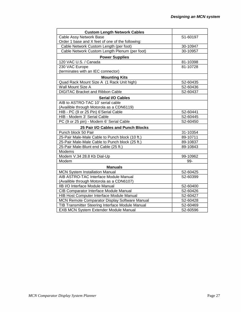
MCN Comparator Display System Planner Page 27
Custom Length Network CablesCable Assy Network BaseOrder 1 base and X feet of one of the following:
S1-60197
Cable Network Custom Length (per foot) 30-10947 Cable Network Custom Length Plenum (per foot) 30-10957
Power Supplies120 VAC U.S. / Canada 81-10398230 VAC Europe(terminates with an IEC connector)
81-10728
Mounting KitsQuad Rack Mount Size A (1 Rack Unit high) S2-60435Wall Mount Size A S2-60436DIGITAC Bracket and Ribbon Cable S2-60437
Serial I/O CablesAIB to ASTRO-TAC 10’ serial cable(Availible through Motorola as a CDN6119)HIB - PC (9 or 25 Pin) 6’Serial Cable S2-60441HIB - Modem 3’ Serial Cable S2-60445PC (9 or 25 pin) - Modem 6’ Serial Cable S2-60450
25 Pair I/O Cables and Punch BlocksPunch block 50 Pair 31-1035425-Pair Male-Male Cable to Punch block (10 ft.) 89-1071125-Pair Male-Male Cable to Punch block (25 ft.) 89-1083725-Pair Male-Blunt end Cable (25 ft.) 89-10843ModemsModem V.34 28.8 Kb Dial-Up 99-10962Modem 99-
ManualsMCN System Installation Manual S2-60425AIB ASTRO-TAC Interface Module Manual(Availible through Motorola as a CDN6107)
S2-60399
IIB I/O Interface Module Manual S2-60400CIB Comparator Interface Module Manual S2-60426HIB Host Computer Interface Module Manual S2-60427MCN Remote Comparator Display Software Manual S2-60428TIB Transmitter Steering Interface Module Manual S2-60469EXB MCN System Extender Module Manual S2-60596

Designing an MCN system
Page 28 MCN Comparator Display System Planner
5.3 Custom System Configuration WorksheetStep Operation
1 Determine the number of networks required.With PC Display, typically only 1 network will be used, so that the PC can see all the comparators.
If you are using ASTRO-TAC comparators and Logic I/O (AIBs and IIBs) exclusively, they can beconfigured as multiple stand-alone networks.
Contact a systems engineer from CTI Products, Inc. at (513) 595-5900 if you have any of thefollowing systems:• Remotely located (> 4000 ft.) comparators• Multiple PC Displays and one or more remotely located comparators• Sub-Comparators• Greater than 20 total CIBs plus AIBs• Greater than 64 total modules (CIBs, AIBs, HIBs, IIBs)• Transmitter Steering (TSAM) Units and TIB modules
For each network, do the steps 2 through 20.2 AIB ASTRO-TAC Interface Modules and cables:
Count the number of AIB ASTRO-TAC Interface Modules to order. If you do not have ASTRO-TAC comparators, skip to step 3:
CDN6119 AIB ASTRO-TAC Interface Module Qty: _________
Order the same quantity of AIB to ASTRO-TAC serial cables:CDN6131 AIB to ASTRO-TAC cable (10 ft.) Qty: _________
Order these items from Motorola.3 IIB Logic I/O Interface Modules:
If you need logic I/O to connect to the I/O lines of a console, calculate the number of IIBInput/Output Modules required. If you want to use only PC display, skip ahead to step 4.
IIBs monitor and control ASTRO-TAC ports in banks of 8. You will need 1 or 2 IIBs per AIB. AnIIB can also monitor one CIB module. See IIB Considerations section for more details.
Count the number of IIBs required for all channels and order that quantity of IIBs:S2-60433 Input/Output Interface Module (IIB) Qty: _________
4 CIB Comparator Interface Modules:Calculate the number of CIB Modules to order. You will need CIB modules for DIGITAC, Spectra-TAC, and TAC comparators and Ericsson / GE analog voters. If you do not have these type ofcomparators, skip to step 5.
Enter the number of CIBs required for each comparator type and order the total quantity:
CIBs for DIGITAC _________CIB for Spectra-TAC _________CIBs for TAC _________CIBs for Ericsson / GE analog voters _________
S2-60442 Comparator Interface Module (CIB) Total Qty: _________Continued

Designing an MCN system
MCN Comparator Display System Planner Page 29
5 Check for maximum number of comparator modules:Calculate the total number of required comparator modules:
AIB Modules from Step 2 _________CIB Modules from Step 4 _________Total
_________(Maximum 20)
If you need more than 20 CIBs and AIBs on one network, call a system engineer at CTI Products,Inc.
6 Order the number of Local PC User Interfaces required. Local PCs are connected to the MCNnetwork (maximum 4000’ total).
S1-60424 Host Computer Interface Module (HIB) with MCN RemoteComparator Display DOS Software:: Qty ____________
Order the same quantity of serial cables (HIB to PC).S2-60441 Serial Cable Kit (includes cable and adapter for
9 pin or 25 pin communication ports): Qty: ____________
Order PCs separately. See the System Hardware Requirements section for details.7 Order the number of Remote (Dial-Up or Leased Line) PC User Interfaces, modems, and serial
cables required. Remote PCs are connected to the MCN network through a HIB Host ComputerInterface located at the network and a pair of modems.
S1-60424 Host Computer Interface Module (HIB) with MCN Remote Comparator DisplayDOS Software: Qty ____________
99-10962 Modem V.34 28.8Kb Dial-Up Qty ____________(For small systems with 1-3 CIB modules, 14.4K modems can also be used.)(Contact CTI Products, Inc. for leased line modems.)
Order the same quantity of serial cables (HIB to Modem).S2-60445 Serial Cable HIB-Modem
(9 pin male to 25 pin female): Qty: ____________
Order PC to Modem Cables:S2-60450 PC (9 or 25 Pin) to Modem Cable Qty: ____________
Order PCs separately. See the System Hardware Requirements section for details.8
abcde
f
g
Calculate the number of mounts required for Local Modules (Local to Comparators):
DIGITAC Quad SingleLocal Modules Rear Mount Rack Mount Wall MountDIGITAC CIBs ________ ________ ________Other CIBs N/A ________ ________AIBs N/A ________ ________Local IIBs N/A ________ ________HIBs (for Modem) N/A ________ ________
Totals Modules ________ ________ ________
Modules per Mount 1 4 1Divide Total Modules by Modules per Mount and round up to the next whole number to calculateSubtotal Mounts:
Subtotal Local Module Mounts ________ ________ ________
Continued

Designing an MCN system
Page 30 MCN Comparator Display System Planner
9
a
b
Calculate the number of mounts required for Extended IIBs(IIBs mounted near the CEB but not in the same rack as the comparator interfaces.):
Quad SingleRack Mount Wall Mount
Extended IIBs ________ ________
Modules per Mount 4 1Divide Extended IIBs by Modules per Mount and round up to the next whole number to calculateSubtotal Mounts:
Subtotal Extended IIB Module Mounts________ ________10
a
Calculate the number of mounts required for Extended HIBs (HIBs mounted near the PC and notin the same rack as the comparator interfaces.)
Quad SingleRack Mount Wall Mount
Extended HIB mounts ________** ________
** Normally, the PCs will be physically separated from each other and you will use one mount perHIB module. You can rack HIBs together if they are all within 6 cable-feet of their PCs.
11
abc
d
efg
Total the number of mounts required based upon the subtotals in the last 3 steps:DIGITAC Quad Single
Local Modules Rear Mount Rack Mount Wall MountLocal Mounts (8g) ________ ________ ________Ext. IIB Mounts (9b) N/A ________ ________Ext. HIB Mounts (10a) N/A ________ ________
Totals Mounts ________ ________ ________
Enter the totals below and order the appropriate quantity of mounts:S2-60437 DIGITAC Bracket and Cable Kit Qty: ________S2-60435 Quad Rack Mount Kit Qty: ________S2-60436 Wall Mount Kit Qty: ________
12
abc
d
e
fgh
Parallel I/O Cabling (25-Pair Cables)Enter the required number of cables for your system. See the Parallel I/O Cabling section formore details.
Male to Male Male to Male Male to BluntCIB Modules 25’ Cable 10’ Cable 25’ CableDIGITAC Bracket/Cable **________ ________ N/ADIGITAC Rack/Wall ________ ________ ________Spectra-TAC, TAC, EGE ________ ________ ________
IIB Modules ________ ________ ________
Totals ________ ________ ________** Order cables only if cables were not ordered with DIGITAC comparator.
Enter the totals below and order the appropriate quantity of items:89-10837 Male to Male Cable 25’ Qty: ________89-10711 Male to Male Cable 10’ Qty: ________89-10843 Male to Blunt Cable 25’ Qty: ________
Continued
Designing an MCN system
MCN Comparator Display System Planner Page 31
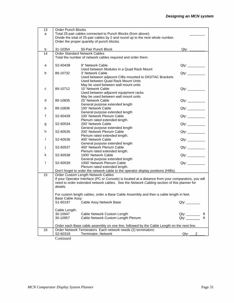
13a
b
Order Punch BlocksTotal 25-pair cables connected to Punch Blocks (from above): ________Divide the total of 25-pair cables by 2 and round up to the next whole number.Order the proper quantity of punch blocks.
31-10354 50-Pair Punch Block Qty: ________14
a
b
c
d
e
f
g
h
I
j
k
l
Order Standard Network CablesTotal the number of network cables required and order them:
S2-60438 9” Network Cable Qty: _________Used between Modules in a Quad Rack Mount
89-10732 3’ Network Cable Qty: _________Used between adjacent CIBs mounted to DIGITAC BracketsUsed between Quad Rack Mount UnitsMay be used between wall mount units
89-10712 10’ Network Cable Qty: _________Used between adjacent equipment racksMay be used between wall mount units
89-10835 25’ Network Cable Qty: _________General purpose extended length
89-10836 100’ Network Cable Qty: _________General purpose extended length
S2-60439 100’ Network Plenum Cable Qty: _________Plenum rated extended length.
S2-60534 200’ Network Cable Qty: _________General purpose extended length
S2-60535 200’ Network Plenum Cable Qty: _________Plenum rated extended length.
S2-60536 400’ Network Cable Qty: _________General purpose extended length
S2-60537 400’ Network Plenum Cable Qty: _________Plenum rated extended length.
S2-60538 1000’ Network Cable Qty: _________General purpose extended length
S2-60539 1000’ Network Plenum Cable Qty: _________Plenum rated extended length.
Don’t forget to order the network cable to the operator display positions (HIBs).15 Order Custom Length Network Cables
If your Operator Interface (PC or Console) is located at a distance from your comparators, you willneed to order extended network cables. See the Network Cabling section of this planner fordetails.
For custom length cables, order a Base Cable Assembly and then a cable length in feet.Base Cable Assy:S1-60197 Cable Assy Network Base Qty: _______
Cable Length:30-10947 Cable Network Custom Length Qty: _______ ft30-10957 Cable Network Custom Length Plenum Qty: _______ ft
Order each Base cable assembly on one line, followed by the Cable Length on the next line.16 Order Network Terminators Each network needs (2) terminators:
S2-60318 Terminator, Network Qty: ___2____Continued

Designing an MCN system
Page 32 MCN Comparator Display System Planner
17
a
b
c
d
ef
Order power supplies:Each power supply can power up to (4) modules at a total cable length of up to 100 feet. See thePower Requirements section for more details.
Total number of modules:(CIBs, AIBs, IIBs, HIBs) ___________
Divide by 4 and round up to next whole number ___________This is the basic number of power supplies needed.
Add power supplies to keep network cable lengths from power supplies to their furthest modules to100 feet or less: ___________
Total Power Supplies (add 17b and 17c) ___________
Order:81-10398 120 VAC US/ Canadian Power Supply Qty ___________81-10728 230 VAC European Power Supply Qty ___________
The 230 VAC power supply has an IEC power connector. Customer must furnish line cord forlocal power connections.
18 Order the appropriate spare modules. See the MCN System Components section for spare partnumbers.
19 Order the appropriate manuals. See the MCN System Components section for spare partnumbers.
20 If this is a Logic I/O system connected to a console, order the required number of Input/Outputcards and comparator display modules (if needed) for the console.

Appendix B Available Documents
MCN Comparator Display System Planner Page 33
6. Appendix B Available Documents
The following manuals are available for the MCN Remote Comparator Display system:
CIB Catalog SheetIIB Catalog SheetHIB Catalog SheetMCN Remote Comparator Display Catalog SheetMCN System Extender Module Catalog Sheet
S2-60425 MCN System Installation ManualS2-60399 AIB ASTRO-TAC Interface Module ManualS2-60400 IIB I/O Interface Module ManualS2-60426 CIB Comparator Interface Module ManualS2-60427 HIB Host Computer Interface Module ManualS2-60469 TIB Transmitter Steering Interface Module ManualS2-60596 EXB MCN System Extender Module ManualS2-60428 MCN Remote Comparator Display Software Manual

Appendix C System Examples
Page 34 MCN Comparator Display System Planner
7. Appendix C System Examples
The following examples show how MCN modules are combined to form various systems, as well as thecapabilities of those systems.
7.1 Example 1 - PC Based System for DIGITAC Comparator-- 8ReceiversFigure 14 shows a system that provides local monitoring and control of up to 8 receivers utilizing a PCas the operator interface. This system assumes the following:• DIGITAC Comparator, 8 Receivers• PC Display• CIB will be mounted on the rear of the Digitac Comparator• North American power supply is required.• 100 feet between PC and comparator• HIB will be rack-mounted in the operator console.
COM 2
COM 1
CA-80019-100
CIB 1
COMPARATOR
HIB
T
P/S
IN
OUT IN
OUT
TLOCAL PC
Figure 14 - 8 Digitac Receivers with PC Display
(P/S = Power Supply, T = Network Terminator)
This is an easy system to order since there is a packaged model for an 8-receiver DIGITAC comparatorwith PC display: Order the following items:
Equipment List for Example System 1
Item Part Nmber Description Qty1 S2-60442 Comparator Interface Module (CIB) 12 S1-60424 Host Computer Interface Module (HIB) and
MCN Remote Comparator Display DOS Software1
3 S2-60441 HIB - PC (9 or 25 Pin) 6’Serial Cable 14 S2-60437 DIGITAC Bracket and Ribbon Cable (for CIB) 15 S2-60435 Quad Rack Mount Size A (1 Rack Unit high) (for HIB) 16 89-10836 100 Ft Network Cable 17 S2-60318 Terminator (1 each) 28 81-10398 Power Supply N. American 1
Order the PC separately. See the System Hardware Requirements section for details.

Appendix C System Examples
MCN Comparator Display System Planner Page 35
7.2 Example 2 - PC Based dial-up System for Spectra-TAC orEricsson Comparator-- 12 ReceiversFigure 15 shows a simple dial-up system to monitor and control 12 or 16 receivers. This systemassumes the following:• Spectra-TAC or Ericsson / GE Comparator, 16 (or 12) Receivers maximum,• Dial-Up PC Display• CIBs & HIB will be rack mounted• Wiring will be directly to the back of the comparator backplanes with no punch blocks.
COM 2
COM 1
CA-80196-100
2
COMPARATORS
HIB
CIB
CIB
T
MODEMMODEM
T
1
P/S
IN
OUT
IN
IN
OUT
REMOTE PC
Figure 15 Dial-Up Display for up to 16 Receivers
Equipment List for Example System 2
Item Part Nmber Description Qty1 S2-60442 Comparator Interface Module (CIB) 22 S1-60424 Host Computer Interface Module (HIB) and
MCN Remote Comparator Display DOS Software1
3 89-10843 Male to Blunt Cable 25’ 24 S2-60445 HIB - Modem 3’ Serial Cable 15 S2-60450 PC (9 or 25 pin) to Modem Cable 16 99-10962 Modem V.34 28.8 Kb Dial-up 27 S2-60435 Quad Rack Mount Size A (1 Rack Unit high) 18 S2-60438 9” Network Cable 29 S2-60318 Terminator (1 each) 210 81-10398 Power Supply N. American 1
Order the PC separately. See the System Hardware Requirements section for details.

Appendix C System Examples
Page 36 MCN Comparator Display System Planner
7.3 Example 3 - Extended Distance Spectra-TAC or EricssonComparator Connected to a Console -- 16 ReceiversA multiple comparator system is shown in Figure 17. This system implements monitoring and controlof 3 different comparators from one console.
This system assumes the following:• Spectra-TAC or Ericsson / GE Comparator, 16 Receivers maximum• Console Display• CIBs will be rack mounted• IIBs will be rack mounted• 400 feet between comparators and console electronics• Punch blocks are used for connection to comparators and to the consoles (Note that the punch
blocks are not shown on the diagram.)
Why in the world would we use an MCN system to connect the comparators to the console electronics?Can’t they be connected directly? Normally, they can. In this case, the console electronics enclosure islocated 400 feet from the comparators. For the logic signals involved, there is a typical limit of about200 cable feet between the comparator and the console electronics. We are using the MCN system aswire extenders to get rid of the 200 ft limitation. Only a single network cable for the MCN system hasto be run the 400 ft. The MCN system can function to 4000 feet. If more than 4000 feet are required,CTI Products can furnish MCN EXB System extender Modules which can extend the network overtelephone lines.
Notice that in this system, one CIB module is being used to control receivers from two comparators(comparators 1 and 2). The only requirement for this setup is that both comparators 1 and 2 are thesame type (in this case they are both Spectra TAC or both Ericsson / GE). Comparator 3 does not haveto be the same type as comparators 1 and 2 since it connects to a different CIB. We are using punchblocks in this system so we can easily connect comparators 1 and 2 to CIB module 1.
CA-80020-100
2
COMPARATORS
CIB
CIB
IIB
IIB
CONSOLEELECTRONICS
1
3
T
P/S
IN
OUT
IN
OUT
TIN
IN
OUT
OUT
400'
P/S
CONSOLE
Figure 16 - 16 Receivers with Console Display
(P/S = Power Supply, T = Network Terminator)

Appendix C System Examples
MCN Comparator Display System Planner Page 37
Equipment List for Example System 3
Item Model/Option Description Qty1 S2-60433 IIB Input/Output Interface Module 22 S2-60442 CIB Comparator Interface Module 23 S2-60435 Quad Rack Mount Size A
(1) for CIBs, (1) for extended IIBs2
4 89-10837 Cable Assy 25 pr M-M 25'(2) for CIBs, (2) for IIBs
4
5 31-10354 Punch Block, 50-Pair(1) for CIBs, (1) for IIBs
2
6 S2-60438 Cable Assy Network 9" 27 S2-60536 400 Ft Network Cable 18 S2-60318 Network Terminator 29 81-10398 Power Supply N. American
(2) needed because of cable length.2
Be sure that the console has console has enough I/O boards and points available. For button and LEDconsoles, be sure that the operator positions have the proper number of Comparator Status DisplayModules. The console may also require re-programming to implement the comparator display.Electronics has (4) B1426 Comparator Interface Modules.

Appendix C System Examples
Page 38 MCN Comparator Display System Planner
7.4 Example 4 - 24 Receivers with Multiple Operator PositionsThe example in Figure 17 shows a much larger system than the previous examples. Three CIBmodules are used to control a total of 24 receivers. The three IIB modules can be used to providecontrol of all receivers from the main console. Each PC in the system can control all receivers as well.The HIB modules provide both local and remote control of all receivers. With the HIB connecteddirectly to the modem, the comparators can be accessed from anywhere that has a dial-up phone line.
This system assumes the following:• (2) Spectra-TAC Comparator (comparators 1 & 2), 8 receivers each• (1) DIGITAC Comparator (comparator 3), 8 receivers• 1000 feet between comparators room and the CEB room• Local PC display in the console electronics room• Dial-up PC for remote monitoring• Console Display using Extended IIBs• All comparators are mounted in the same rack.• The Dial-up HIB and the CIBs for the Spectra-TAC comparators will be rack mounted in same
cabinet as the comparators• CIBs will be connected to Spectra-TAC comparators with blunt-end cables wired directly to the
back of the comparators.• The CIB for the DIGITAC comparator will mount to the rear of the comparator with a Digitac
Bracket and Cabling kit.• IIBs will be rack mounted in the CEB room• The HIB in the CEB room will be mounted under a desk-top using a wall-mount kit.• Punch blocks are used for connection between the IIBs and the consoles CEB (punch blocks are
not shown on the diagram.)
COM 2
COM 1
COM 2
COM 1
CA-80017-100
2
COMPARATORSHIB
CIB
CIB
CIB
T
MODEMMODEM
HIB
IIB
IIB
IIBT
CONSOLEELECTRONICS
1
3
P/S
OUT
OUT
OUT
OUT
IN
IN
IN
IN
IN
OUT IN
IN
IN
OUT
OUT
OUT
P/S
REMOTE PC
LOCAL PC
CONSOLE
Figure 17 - 24 Receivers with Multiple Operator Console and PC Positions
(P/S = Power Supply, T = Network Terminator)
Power is provided to this MCN system from two power supplies. One supply power one HIB moduleand all three CIB modules. Another supply power the second HIB module and the three IIB modules.

Appendix C System Examples
MCN Comparator Display System Planner Page 39
This system allows parallel status and control of three comparators from three operator locations. If anoperator at one location force votes a receiver, the other two operator stations will show that receiver asvoted. Or, if an operator disables a receiver, all other operator stations will also show that receiver asdisabled. If one of the comparators signals that a receiver is voted, all three stations will show thereceiver being voted.
Equipment List for Example System 4
Item Model/Option Description Qty1 S2-60433 IIB I/O Interface Module 32 S2-60442 CIB Comparator Interface Module 33 S1-60424 Host Computer Interface Module (HIB) with MCN
Remote Comparator Display DOS Software for Localand Dial-Up PC
2
Order Separately PCs for Local and Dial-Up display ** 24 S2-60441 Serial Cable Kit (includes cable and adapter for 9 pin
or 25 pin communication ports) for local HIB1
5 S2-60445 Serial Cable for HIB to Modemfor Dial-Up HIB
1
6 99-10962 V.34 Dial-Up Modems 27 S2-60450 PC (9 or 25 pin) - Modem 6’ Serial Cable 18 S2-60437 DIGITAC Bracket and Cable Kit 19 S2-60435 Quad Rack Mount Size A
(1) for Spectra-TAC CIBs, (1) for extended IIBs2
10 S2-60436 Wall Mount Kit(For mounting HIB in console electronics room)
1
11 89-10837 Cable Assy 25 pr M-M 25'for IIBs
3
12 89-10843 Male to Blunt Cable 25’for Spectra-TAC Comparators
2
13 31-10354 Punch Block, 50-Pair (for IIBs) 214 S2-60438 Cable Assy Network 9"
(1) Dial-up HIB to Spectra-TAC CIB(1) Spectra-TAC CIB to Spectra-TAC CIB(2) IIB to IIB
4
15 89-10732 3’ Network CableQuad rack mount to Digitac CIB
1
16 89-10835 25’ Network CableHIB in CEB room to IIB Quad rack mount
1
17 S2-60538 1000 Ft Network CableDIGITAC Comparator CIB Module to HIB in consoleelectronics room
1
18 S2-60318 Network Terminator 219 81-10398 Power Supply N. American
(2) needed to power (8) modules2
There is one limitation of a system which uses both HIBs and IIBs together to control the samecomparator. The console Disable LED can get out of sync if the PC re-enables a receiver. See theAppendix E System Limitations when using HIB and IIB Modules Together section for details.
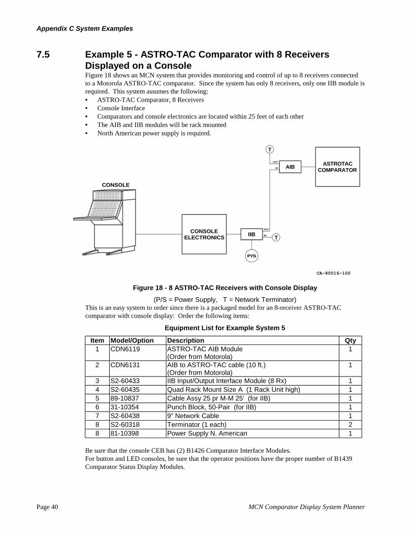
Appendix C System Examples
Page 40 MCN Comparator Display System Planner
7.5 Example 5 - ASTRO-TAC Comparator with 8 ReceiversDisplayed on a ConsoleFigure 18 shows an MCN system that provides monitoring and control of up to 8 receivers connectedto a Motorola ASTRO-TAC comparator. Since the system has only 8 receivers, only one IIB module isrequired. This system assumes the following:• ASTRO-TAC Comparator, 8 Receivers• Console Interface• Comparators and console electronics are located within 25 feet of each other• The AIB and IIB modules will be rack mounted• North American power supply is required.
CA-80016-100
IIBCONSOLE
ELECTRONICS
COMPARATORASTROTAC
AIBOUT
P/S
IN
CONSOLE
IN
OUT
T
T
Figure 18 - 8 ASTRO-TAC Receivers with Console Display
(P/S = Power Supply, T = Network Terminator)This is an easy system to order since there is a packaged model for an 8-receiver ASTRO-TACcomparator with console display: Order the following items:
Equipment List for Example System 5
Item Model/Option Description Qty1 CDN6119 ASTRO-TAC AIB Module
(Order from Motorola)1
2 CDN6131 AIB to ASTRO-TAC cable (10 ft.)(Order from Motorola)
1
3 S2-60433 IIB Input/Output Interface Module (8 Rx) 14 S2-60435 Quad Rack Mount Size A (1 Rack Unit high) 15 89-10837 Cable Assy 25 pr M-M 25' (for IIB) 16 31-10354 Punch Block, 50-Pair (for IIB) 17 S2-60438 9” Network Cable 18 S2-60318 Terminator (1 each) 28 81-10398 Power Supply N. American 1
Be sure that the console CEB has (2) B1426 Comparator Interface Modules.For button and LED consoles, be sure that the operator positions have the proper number of B1439Comparator Status Display Modules.

Appendix C System Examples
MCN Comparator Display System Planner Page 41
7.6 Example 6 - Multiple Remote PCs using EXB SystemExtendersWhen only one remote PC is needed to monitor remote comparators, a HIB Host Computer InterfaceModule and a pair of modems are used. If multiple PCs are required, that method would requiremultiple telephone lines, one for each PC.
Figure 19 shows a way to connect multiple PCs to remote comparators using only one phone line. Thepair of EXB System Extender Modules extend the MCN network at the remote site to the local site.The remote network of CIB Comparator Interface Modules is essentially re-created at the local site.Multiple PCs are then connected to the local MCN network through standard HIB Host ComputerInterface Modules. The number of PCs at the local site is limited only by standard MCN systemlimitations.
HIB
T
OUT
IN
P/S
EXBOUT
IN
T
P/S
CIB
CIBOUT
OUT
IN
IN
OUT
IN
CIBOUT
IN
T
TO COMPARATORS
LEASED LINE
REMOTE SITE
CA-80185-100
EXB
HIB
T
OUT
IN
COM 2
COM 1
COMPARATORDISPLAY
COM 2
COM 1
COMPARATORDISPLAY
Figure 19 Multiple Local PC Displays with Remote Comparators using EXB Modules
Systems using EXB System Extender Modules are considered custom designed systems. Pleasecontact a CTI Products application engineer for help in designing a system.

Appendix C System Examples
Page 42 MCN Comparator Display System Planner
7.7 Example 7 - Multi-Site Comparator NetworksZone & Master/Slave (Sub) ComparatorsMany voting systems covering a large geographic area will have comparators located at multiple sites.In this way, comparators for particular zones are located close to their receivers, with the voted audiobrought back to the dispatch center on a single phone line for each zone. This greatly reduces thelength and cost of the associated telephone lines.
Some state-wide or city-wide systems use Master-Slave (or Sub-Comparator) systems. In these systems,the City-Wide or State-Wide channel is broken into zones, each with its own comparator, called Slaveor Sub-Comparators. The voted audio from the Sub-comparators is brought back to a Mastercomparator at the dispatch location. The Master comparator then picks the best signal from the sub-comparators.
Figure 20 shows a way to monitor and control the comparators in a Zone or Master/Slave (Sub)Comparator system. Each of the remote sites has its comparators connected to CIB modules on its ownMCN network. Each remote site is connected back to the central (master) site through a pair of EXBSystem Extender modules. The master site has its Master Comparator connected to CIB ComparatorInterface Modules.
Since all the MCN networks are connected together at the master site, the PCs there can monitorcomparators at multiple sites simultaneously. If, for instance, a wide-area channel has 3 sub-comparators, the PCs can monitor all 3 sub-comparators and the master comparator simultaneously.
COM 2
COM 1HIB
HIB
T
T
OUT
IN
OUT
IN
P/S
EXBOUT
IN
OUT
IN
P/S
CIB
CIBOUT
OUT
IN
IN
TO LOCALCOMPARATORS
T
P/S
CIB
CIBOUT
OUT
IN
IN
OUT
IN
CIBOUT
IN
T
T
P/S
CIB
CIBOUT
OUT
IN
IN
OUT
IN
CIBOUT
IN
T
TO COMPARATORS
TO COMPARATORS
LEASED LINES
LEASED LINES
COMPARATORDISPLAY
REMOTE SITE 1
REMOTE SITE N
CA-80183-100
EXB
EXB
EXB
COM 2
COM 1
COMPARATORDISPLAY
Figure 20 Multiple Remote Comparator Sites combined with EXB Modules
Systems using EXB System Extender Modules are considered custom designed systems. Pleasecontact a CTI Products application engineer for help in designing a system.

Appendix C System Examples
MCN Comparator Display System Planner Page 43
7.8 Example 8 - Controlling Transmitter Steering Systems usingTIB ModulesFigure 21 shows a single-channel 8-receiver comparator system, a TSAM Transmitter Steering Unit,and a TIB Transmitter Steering Interface Module.
Systems using TIB Transmitter Steering Interface Modules and TSAM Transmitter Steering Units areconsidered custom designed systems. Please contact a CTI Products application engineer for help indesigning a system.
COM 2
COM 1
CA-80119-100
CIB 1
COMPARATOR
HIB
P/S
OUT IN
TIN OUT
IN
OUTT TSAMTIB
VOTE LINES
FORCE SELECT
TX SELECT
LOCAL PC
Figure 21 Controlling a Transmitter Steering System with a TIB Module
Systems using EXB System Extender Modules are considered custom designed systems. Pleasecontact a CTI Products application engineer for help in designing a system.

Appendix D Module Addressing and Receiver Banks
Page 44 MCN Comparator Display System Planner
8. Appendix D Module Addressing and ReceiverBanks
8.1 Module AddressingEach MCN module is identified by a unique address that must be set at installation time. This addressis specified by the combination of a Group number and a Module number. The Group and Modulenumbers are assigned with the rotary switches on either the front or back of the module. Whenever theGroup or Module number is changed, the module must be reset or power cycled for the change tooccur.
897 ABC
D
EF01234
5
6897 AB
CD
EF012345
6897 AB
CD
EF01234
56
CA-80046-100
MODULEGROUP
Figure 22 - Group and Module Switches
Figure 22 shows a view of the Group and Module switches. Valid ranges of these switches are:• Group number = 00 through FE
• Module number = 0 through F (16 modules per group)
Group number FF is reserved and should not be used for any module in the system. If Group numberFF is assigned to a module, the module, when reset, will lock on its ERR LED and halt. All modules ina system must have unique addresses. If two or more modules are set to the same address, your systemwill not work properly and you could have unintended operation. Other than those restrictions, anyGroup/Module combination can be used for any module.
Certain MCN modules must have two addresses specified. One is for the MCN module that it willoperate with and the other is for the module itself. The IIB module requires this dual addressinformation. Refer to the IIB’s hardware reference manual for details about setting the two addresses.
Assign all Comparator I/O Modules to the same Group or set of Groups (if you have more than 16modules), typically beginning with Group 00, Module 0 and progressing sequentially. Althoughmodules can be added at higher addresses later, if you have plans to expand a channel, you may want toleave module addresses open for the expansion.
Assign all User Interface Modules to the same Group or set of Groups (if you have more than 16modules), beginning with Group 80, Module 0.
When using the HIB User Interface Module with the MCN Remote Comparator Display software, onlyfour Groups can be monitored and controlled at a time on one PC. If you are going to be using thisUser Interface Module, plan the addresses of your Comparator I/O modules so that you use as fewdifferent Groups as possible.
In a large system, you can monitor and control more than 4 Groups on a PC using the HIB; you are justlimited to 4 groups simultaneously. For these types of large systems, group your modules so that all thereceivers you may want to watch simultaneously are within the same 4 groups. Large systems (over 20CIB and AIB modules) will be custom designed by CTI Products.

Appendix D Module Addressing and Receiver Banks
MCN Comparator Display System Planner Page 45
8.2 Receiver BanksThe CIB parallel Comparator Interface Module controls and monitors 8 receivers. The AIB supportsall 16 receivers of an ASTRO-TAC comparator.
For Comparator I/O Modules such as the AIB module that support more than 8 receivers, the receiversare grouped into banks of 8 receivers. Some User Interface Modules, such as HIBs operating with theMCN Remote Comparator Display software support only bank 0. Other User Interface Modules, suchas the IIB, can be configured to control any one of the 8 banks.
Below is a list of the MCN banks and the receivers contained in those banks.
Bank Receiver Numbers0 1 through 81 9 through 162 17 through 243 25 through 324 33 through 405 41 through 486 49 through 567 57 through 64
Table 8 - MCN Receiver BanksIn the example shown in Figure 23, the ASTRO-TAC comparator supports 16 receivers. The AIBdivides the receivers into two banks (receiver banks 0 and 1) for its communications with the UserInterface Modules (the IIB modules). Two IIBs are installed in the example system to support these 16receivers. When the IIBs were installed, each had to be configured (through front panel optionswitches) for the bank of receivers that each will be monitoring. The first IIB is configured to monitorreceivers 1 through 8 (bank 0). The second IIB is configured to monitor receivers 9 through 16 (bank1). With this configuration, the console can monitor and control receivers 1 through 16.
CA-80044-100
OUT
P/S
IN
IN
OUT
TT
COMPARATORCONSOLEELECTRONICS
IN
OUT
AIBASTRO-TAC
13 RECEIVERS
IIBBANK 0
IIBBANK 1
CONSOLE
Figure 23 - MCN Bank Configuration Example

Appendix E System Limitations when using HIB and IIB Modules Together
Page 46 MCN Comparator Display System Planner
9. Appendix E System Limitations when using HIBand IIB Modules Together
Because the console VOTE and DISABLE lines are bi-directional, the console’s LEDs will be lit if theconsole’s outputs are active. Because of this, the console could still indicate a DISABLE or VOTE ona receiver even if there is a problem in the network cabling or the Comparator I/O Module. Take forexample the system shown in Figure 4.
When the DISABLE button on the console is pressed, the DISABLE LED on the console willimmediately turn on and stay on after the DISABLE button is released since it is a latched output. Theconsole will show a Disable condition, even if there was a problem with the network or the AIB.
Likewise, in a mixed system with HIBs and IIBs, if a receiver is disabled through the console (with itslatching output) and then a PC user re-enables the receiver, the receiver will actually be enabled, butthe console will show it as disabled. In this case, the console operator must press the disable buttonagain to release the latch in the console.

Appendix F Warranty
MCN Comparator Display System Planner Page 47
10. Appendix F Warranty
Standard Limited Hardware WarrantyLIMITED WARRANTY. Equipment manufactured by CTI Products, Inc. is warranted to be free from defects inmaterial and workmanship for a period of ONE (1) YEAR from date of installation, up to a maximum of 14 months fromshipment from CTI Products, Inc. Under this warranty, our obligation is limited to repairing or replacing any equipmentproved to be defective by our inspection within one year of sale to the original purchaser. This warranty shall not applyto equipment which has been repaired outside our plant in any way, so as to, in the judgment of CTI Products, Inc. affectits stability or reliability, nor which has been operated in a manner exceeding its specifications, nor which has beenaltered, defaced, or damaged by lightning.
CUSTOMER REMEDIES. In the event of a defect, malfunction, or failure to conform to specifications established bythe seller during the period shown, the customer shall call CTI Products, Inc. to obtain a Return Authorization Numberand return the product or module, shipping and insurance prepaid. CTI Products, Inc., will then at its option, either repairor replace the product or module and return it, shipping prepaid, or refund the purchase price thereof. On-site labor at thepurchaser's location is not included in this warranty.
EQUIPMENT NOT MANUFACTURED BY CTI Products, Inc. Equipment not manufactured by CTI Products, Inc. isexcluded from this warranty, but is subject to the warranty provided by its manufacturer, a copy of which will be suppliedto you upon specific written request.
NO OTHER WARRANTIES. The foregoing constitutes the sole and exclusive remedy of the buyer and exclusiveliability of CTI Products, Inc., AND IS IN LIEU OF ANY AND ALL OTHER WARRANTIES EXPRESSED ORIMPLIED OR STATUTORY AS TO MERCHANTABILITY, FITNESS FOR PURPOSE SOLD, DESCRIPTION,QUALITY, PRODUCTIVENESS OR ANY OTHER MATTER.
NO LIABILITY FOR CONSEQUENTIAL DAMAGES. WITHOUT LIMITING THE FOREGOING, IN NO EVENTSHALL CTI PRODUCTS, INC. OR ITS SUPPLIERS BE LIABLE FOR ANY DAMAGES WHATSOEVER(INCLUDING, WITHOUT LIMITATION, SPECIAL, INCIDENTAL OR CONSEQUENTIAL DAMAGES OR FORLOSS OF BUSINESS PROFITS, BUSINESS INTERRUPTION, LOSS OF BUSINESS INFORMATION, OR OTHERPECUNIARY LOSS) ARISING OUT OF THE USE OF OR INABILITY TO USE CTI PRODUCTS, INC.EQUIPMENT BY PURCHASER OR OTHER THIRD PARTY, WHETHER UNDER THEORY OF CONTRACT,TORT (INCLUDING NEGLIGENCE), INDEMNITY, PRODUCT LIABILITY OR OTHERWISE, EVEN IF CTIPRODUCTS, INC. HAS BEEN ADVISED OF THE POSSIBILITY OF SUCH DAMAGES OR LOSSES. IN NOEVENT SHALL CTI PRODUCTS, INC.’S, LIABILITY EXCEED THE TOTAL AMOUNT PAID BY PURCHASERFOR THE EQUIPMENT GIVING RISE TO SUCH LIABILITY.

Appendix G Customer Support
Page 48 MCN Comparator Display System Planner
11. Appendix G Customer Support
For Pre- and Post-sale support,large systems, custom system design, or special applications contact:
CTI Products, Inc.1211 West Sharon RoadCincinnati, Oh 45240
Phone: (513) 595-5900 Fax: (513)595-5983.8:30 to 5:00 Eastern time

Appendix H Glossary
MCN Comparator Display System Planner Page 49
12. Appendix H Glossary
16 I/O Module This is a generic term for the B1426 Comparator Interface Module in the CEB of aCentracom Series II console.
AIB Module ASTRO-TAC Comparator Interface Module. The AIB Module connectsMotorola’s ASTRO-TAC comparator to the MCN network.
CEB Central Electronics Bank for a Centracom Series II (or later) console.
CIB Module Comparator Interface Module. The CIB module connects various types of parallelI/O comparators (such as DIGITAC, Spectra-TAC and TAC comparators) to theMCN network. A CIB module controls 8 receivers.
Do not confuse this with the B1426 Comparator Interface Module which plugsinto the CEB of a Centracom Series II console
Comparator I/O Module This is a generic term used to describe the modules that connect a comparator tothe MCN network. Comparator I/O Modules include the AIB ASTRO-TACInterface Module and the CIB Comparator Interface Module.
EXB Module The EXB System Extender Modules are used in pairs to extend the MCN networkto distances greater than 4000 feet. These operate over leased telephone lines ormicrowave channels.
HIB Module Host Computer Interface Module. The HIB module provides a connection to theMCN network for a PC. It uses a serial interface on the PC and works with CTIProducts’ MCN Remote Comparator Display (MCN RCD) software to providecomparator monitoring and control.
IIB Module Input/Output Interface Module. The IIB module is a User Interface Module thatconnects to the MCN network. It provides discrete, parallel I/O points forconnection to a console system. It is typically connected to B1426 Comparator I/OModules in the CEB.
MCN System This is the name for CTI Products’ Monitoring and Control Network system.Modules in the MCN System product line include the AIB, IIB, CIB, and HIBmodules.
MCNCFG This is the configuration software that is included in a PC-based MCN system.This software allows the user to custom-configure the comparator display screensused with the MCN Remote Comparator Display System program.
MCN RCD This is the MCN Remote Comparator Display software. It is used in PC-basedcomparator display system.
RCD Remote Comparator Display
TIB Module Transmitter Steering Interface Module. The TIB module works with a CIB moduleand an external Transmitter Steering Unit. The TIB module sends Selected TXindications back to the HIB module (through the CIB module). It also acceptsForce Vote signals from the CIB module to force-steer a transmitter site.
User Interface Module This is a generic term used to describe the modules that connect a user interface(console or PC) to the MCN network. User Interface Modules include the IIBInput/Output Interface Module for use with consoles and the HIB Host ComputerInterface Module for use with PCs.