monitor 41 heating system system owner's guide ... troubleshooting guide 24 i ... following...
TRANSCRIPT

MONITOR 41TM
Heating SystemOwner's Guide
IMPORTANT : READ THIS OWNER'S GUIDE CAREFULLY ANDTHOROUGHLY BEFORE INSTALLING OR USINGYOUR HEATER.RETAIN THIS OWNER'S GUIDE FOR FUTUREREFERENCE.
•4 )
u
4AP\M O N I T O R P R O D U C T S I N C

SAFETY ALERT SYMBOLThese symbols appear at important safety precautions and should be understoodand followed by the owner to assure safe operation of the heater.
For Quick ReferencePage
SECTION A: ^Important Caution 1SECTION B: Specifications 5
Special Features 5Safety Features 5
SECTION C: Tools Needed for Heater Installation 6Accessories You May Need • 7Window Installation 7Flue Pipe Extentions 8
SECTION D: Heater Installation 9Flue Pipe Clearances 10
SECTION E: Fueling 15Fueling Options Available -"15External Tank Installation 15Empty Fuel Tank 16
SECTION F: Starting Instructions 17SECTION G: Adjusting Room Temperature 18SECTION H: Turning Off the Heater 18SECTION I : Relighting the Heater 18SECTION J: Programming the Heater 19
Setting the Clock 19Programming for Automatic Heater Operation 20Manual Operation 20
SECTION K: Protective Features 21Loss of Power-Automatic Reset 21Electrical Fuse 21Overheat Prevention 21
SECTION L: Care of the Heater 22SECTION M: Troubleshooting Guide 24
i
COPYRIGHT © MONITOR PRODUCTS, INC.,

SECTION A MONITOR 41
IMPORTANT CAUTION
AWARNINGUSE ONLY CRYSTAL CLEAR KEROSENE. NEVERUSE GASOLINE, WHITE GAS, CAMP FUEL OROTHER FLAMMABLE LIQUIDS. USE OF SUCHFUELS CAN RESULT IN AN EXPLOSIVE FIRE ANDCAUSE SEVERE INJURY.
KEROSENE ONLY
GAS
ACAUTION1. Make sure that there is no fuel leakage from fuel tank and fuel pipe joint.
2. Make sure that flue pipe (exhaust pipe, air supply hose) is connectedproperly.

3. Keep heater clean and do not store any flammable items on or near theheater.
4. Don't use the heater for drying clothes.
5. Should anything abnormal occur in the heater, remain calm, turn it off (donot unplug) and contact your Monitor dealer.
6. Risk of burns.Flue pipe and louver may have high surfacetemperature.

7. Do not place yourself or others too close to the heater.
8. Installation of heater in extreme humidity or dust areas is notrecommended.Any removal of unit parts or remodeling is strictly forbidden.
Do not sit on the heater.Placing ornaments or plants is not recommended.Excess heat may cause damage to ornament or plant and overwateringor spilling of water may cause shock to you or damage to theheater.
10. In areas of heavy snow accumulation, flue pipe may need to be installed higher to avoid being buried.In open areas with strong wind, a wind break may be necessary to avoid exhaust gases being blownback into the intake and causing poor combustion.
u_ 24"min
LongExtensionkit
"fMust be higher.
Snow

11. Do not install nor exhaust the flue pipe into a crawl space or underneath floor nor into a flue or chimney.
X•Flue Duct
12. OPERATING ALTITUDES HIGHER LIMITSThis heater is designed to be used no higher than 3000FT above sea level. Do not operate at altitudeshigher than 3000FT above sea level.
13.0PERATING TEMPERATURE LIMITSPlease use the Monitor within the range of temperatures indicated by the shaded area shown on the graphbelow.
Operating Temperature Limits
-10 0 20
Inside Area Temperature f F)
40 60
Point AInside Area Temperature — 4°FOutside Temperature — 22°F
Point BInside Area Temperature 60TOutside Temperature — 40°F
SECTION B4/IPI
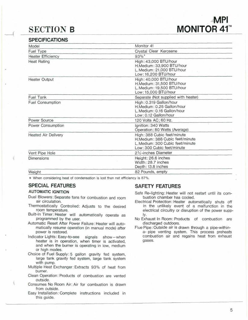
MONITOR 41SPECIFICATIONSModel Monitor 41Fuel Type Crystal Clear KeroseneHeater Efficiency 93%*Heat Rating High: 43,000 BTU/hour
H.Medium: 33,900 BTU/hourLMedium: 21,000 BTU/hourLow: 16,200 BTU/hour
Heater Output High: 40,000 BTU/hourH.Medium: 31,500 BTU/hourL Medium: 19,500 BTU/hourLow: 15,OOP BTU/hour
Fuel Tank Separate (Not supplied with heater)Fuel Consumption High: 0.319 Gallon/hour
H.Medium: 0.25 Gallon/hourL Medium: 0.16 Gallon/hourLow: 0.12 Gallon/hour
Power Source 120 Volts AC; 60 Hz.Power Consumption Ignition: 340 Watts
Operation: 80 Watts (Average)Heated Air Delivery High: 388 Cubic feet/minute
H.Medium: 388 Cubic feet/minuteL.Medium: 300 Cubic feet/minuteLow: 300 Cubic feet/minute
Vent Pipe Hole 2K-inches DiameterDimensions Height: 26.6 inches
Width: 28.7 inchesDepth: 13.8 inches
Weight 82 Pounds, empty
* When considering heat of condensation is lost then net efficiency is 87%.
SPECIAL FEATURESAUTOMATIC IGNITIONDual Blowers: Separate fans for combustion and room
air circulation.Thermostatically Controlled: Adjusts to the desired
room temperature.Built-in Timer: Heater will automatically operate as
programmed by the user.Automatic Reset After Power Failure: Heater will auto-
matically resume operation (in manual mode) afterpower is restored.
Indicator Lights: Easy-to-see signals show—whenheater is in operation, when timer is activated,and when the burner is operating in low, mediumor high modes.
Choice of Fuel Supply: 5 gallon gravity fed system,large tank gravity fed system, large tank systemwith pump.
Multiple Heat Exchanger: Extracts 93% of heat fromburner.
Clean Operation: Products of combustion are ventedoutside.
Consumes No Room Air: Air for combustion is drawnfrom outside.
Easy Installation: Complete instructions included inthis guide.
SAFETY FEATURESSafe Re-lighting: Heater will not restart until its com-
bustion chamber has cooled.Electrical Protection: Heater automatically shuts off
in the unlikely event of a malfunction in theelectrical circuitry or disruption of the power supp-ly.
No Exhaust In Room: Products of combustion aredischarged outdoors.
Flue Pipe: Outside air is drawn through a pipe-within-a- pipe venting system. This process preheatscombustion air and regains heat from exhaustgases.

SECTION CBefore installing your heater, be sure to check and comply with local and state building and electrical codesthat may apply to vented Heaters in your area. Permanent wiring must be installed by a licensed electrician.
TOOLS NEEDED FOR HEATER INSTALLATIONCheck the following charts to be sure you have all the tools required to install your Monitor 41 Heating System.
STANDARD TOOLS APPLICATION
Phillips Head Screwdriver Installation of Heater PartsSteel Tape Measure Taking MeasurementsPen or Pencil Marking Drilling LocationExterior Caulk Caulking Between Packing and WallYardstick or Long Straight Edge Checking Angle of Hole for Flue PipeSoapy Water Lubricating Sleeve Hardware
SPECIAL TOOLS APPLICATION
Electric Drill Accommodating Hole Saw and Drill Bit2% inch Hole Saw Attachment Cutting Hole for Flue PipeLong y± inch Drill Bit Drilling Pilot Hole Through WallLevel Checking Angle of Hole for Flue Pipe and for checking
heater level.
Rg. 1

ACCESSORIES YOU MAY NEEDCheck the list below and see your MPI dealer for accessories you may need or want for installation of your heat-ing system.
ACCESSORY APPLICATION
Medium Flue Pipe P/N 8206 For use where wall thickness is up to 14% inchesLong Flue Pipe P/N 8005 For use where wall thickness is up to 20 inchesWall Mounted Fuel Tank P/N 8201 For small capacity, gravity fed outside fuel supplyElectric Suction Pump P/N 1100
1101For use with large capacity tank where gravity feed is notpractical
Window Installation Kit P/N 8208, 8209(See Window Installation below)
For use where "through-the window" flue pipe installationis desired
Extra Short, Short, Medium orLong Extension Kit or Elbow Adapter Kit(See Flue Pipe Extensions, page 7)
For use where "standard" installation is not practical
Fitting and Tank For large capacity fueling: To be dealer installed
WINDOW INSTALLATIONThe use of "through-the-window" installation for yourflue pipe will require a window installation kit and oneof the 4 (Extra short, Short, medium or long) extensionkits.
In order to determine wihch extension kit is requiredmeasure the distance from the floor to the TOP ofyour window sill (see Figure 2) and refer to the chartbelow.
IF THE MEASUREMENT IS:
\Fig. 2
YOU NEED:
20% to 25 inches Extra Short Extension Kit P/N 8212
25 to 33% inches Short Extension Kit P/N 8204
33% to 51y* inches Medium Extension Kit P/N 8203
to86K inches Long Extension Kit P/N 8202
Elbow Adapter Kit P/N 8213
NOTE: Window kit installation is prohibited when the window is required to meet the local building code require-ments for ventilation, emergency escape, or rescue.One or more Elbow Adapter Kit may be needed if heater is installed on inside wall.

MONITOR 41• -
FLUE PIPE EXTENSIONSFour standard extension kits are available from yourMonitor dealer. Most installations can de made withone of these kits. In special cases, custom installa-tions may be required. These may be made with com-ponents purchased from your dealer.
In any installation the following limitations MUST NOTBE EXCEEDED:1. The total length of either the intake or exhaust pipe
should not exceed 10 feet with 3 elbows, 13 feet with2 elbows, or 16 1/2 feet with 1 elbow.
2. These elbows should include the one used at theheater but not the one on the air supply hose nor theintegral bends in the flue pipe. (See Figure 3)
3. The correct damper as shown on Page 13 must beused.
Exhaust Elbow Air Supply Hose
90° Joint Flue Pipe
Fig. 3 * Do not count
8

SECTION D4API
MONITOR 41HEATER INSTALLATIONStep 1: Fill Out Owner Registration CardFill out your owner registration card and mail it as soonas possible.
Step 2: Check for PartsBefore discarding packing materials, be sure you havelocated the following:
Flue PipeSleeve NutSpill TrayRoom Temp. Sensor (attached to the rear of theheater)Cardboard Template"STANDARD" Damper"EXTENSION" DamperWall Clamps (2)Rubber PackingJoint PipeCloth Insulation CoverOuter FlangePipe HolderSmall Bag of Screws
Tapping, Type A -Tapping, Type A —
For securingsleeve andwall clamps
For securingwall clamps
SIZE
Tapping Tapping
Fig. 4
Step 3: Choose a Location for Your HeaterIn choosing a location for your heater, the followingguidlines must be considered:• The heater MAY be installed on combustible floors.• The area around the heater should be free of obs-
tacles that might interfere with the free flow of air.Allow the clearances shown in Figure 5.
Rg. 5
• The heater must not be installed in a combustiblefireplace.
• An AC wall outlet must be within reach of the hea-ter's power cord. Extension cords must not beused.
• The area outside where the flue pipe will emergeshould be free of foliage, fuel storage tanks andflammable objects. Air should circulate freely inthe area. Allow the clearances shown in Figure 6 onthe next page.
• The wall where flue pipe hole will be cut should befree of plumbing pipes, electrical wires, studs, airducts and other obstacles.
NOTE: Use the cardboard template provided with yourheater for flue pipe location.
9

MONITOR 41™FLUE PIPE CLEARANCESFlue pipe installations should provide for venting to an unconfined space through which there is a free flow ofoutdoor air. Clearances to adjacent walls or obstacles must comply with the requirements shown below.
Frontal Clearance
ACAUTION:Do not attach anything onto the outletof the flue pipe.
Combustible mnm" T"" minimim
24" (60cm)or more
WallAny constructionabove Flue Pipemust not comewithin 24" (60cm)
cm) of front obstacle
or 4 - 24" (60cm)more or more
Flue Pipe~Front Obstacle
ff (20cm)or more
Ground or slab surface
Overhead ClearanceCombustible -»
Non-combustible
Combustible
Ground or slab surface
Side Clearance BodyClamp
Heater-
Side obstaclei mi i i i i i imi i i i i i i i i i i i i iu iu
18" (45cm)or more
Flue Pipe-Wall
IMPORTANT:(1) In areas of heavy snow falls, ground surface clearance
must be increased according to average snow falls, toprevent flue pipe from being buried.
1Must be higher.
(2) In open area with strong wind, a wind break may benecessary.
u- 24"min -«<
kit
Snow
Fig. 6
10

Step 4: Drill a Pilot HoleNOTE: The following directions apply to "standard"
installation. For other methods, follow Instruc-tions included with accessory kits.
For walls up to 8% inches thick, use a shortflue pipe; for walls up to 14)4 inches thick, usea medium flue pipe; and for walls up to 20 inc-hes thick, use a long flue pipe.
Position of hole- • Template
Use the template to position the hole to be drilled.The "red dot" indicates the exact center of the hole.Using an electric drill and a long drill bit, make a pilothole through the wall (Figure 7). Be Sure the holeextends through the outside wall.
/^CAUTION: The opening on the insidewall should be approximately% inch higher than on the out-side wall so the flue pipe willslope downward when install-ed. This will allow condensa-tion to drain outdoors.
Fig. 7
Step 5: Cut the Hole for the Flue pipeUsing a hole saw attachment and an electric drill, cuta 2^4 inch diameter hole through the inner and outerwalls (Figure 8).
After the hole is cut, use a straight edge and a levelto be sure the inside opening is approximately Yz inchhigher than the outside opening.
Wall
Room |'v"vj Outdoor
Fig. 8
Step 6: Install the Flue PipeFrom INSIDE the building, insert the flue pipe (witharrow pointing "up") into the hole. Fasten the flue pipe
with the 3 #8x% tapping screws (Figure 9). (See Fig-ure 4 for screw size and application.)
tapping screw
Fig. 9
11

Step 7: Install the Outer FlangeApply caulking material to the inside ridge of the rub-ber packing (Figure 10).
-f V-
Fig. 10
Holding the "UP" mark to the top, slide the rubber pa-cking onto the sleeve (caulk side to the wall).
NOTE:If it is difficult to slide the packing onto thesleeve, apply soapy water to the inside of thepacking.
Once the rubber packing is in place, slide the outerflange onto the sleeve with the conical side pointingoutward (Figure 11).Screw the flue pipe nut onto the flue pipe grooves,and tighten it firmly (Figure 11).
Rubber Packing
Outer Flange
Flue Pipe Nut
Fig. Tl
12
MPIMONITOR 41
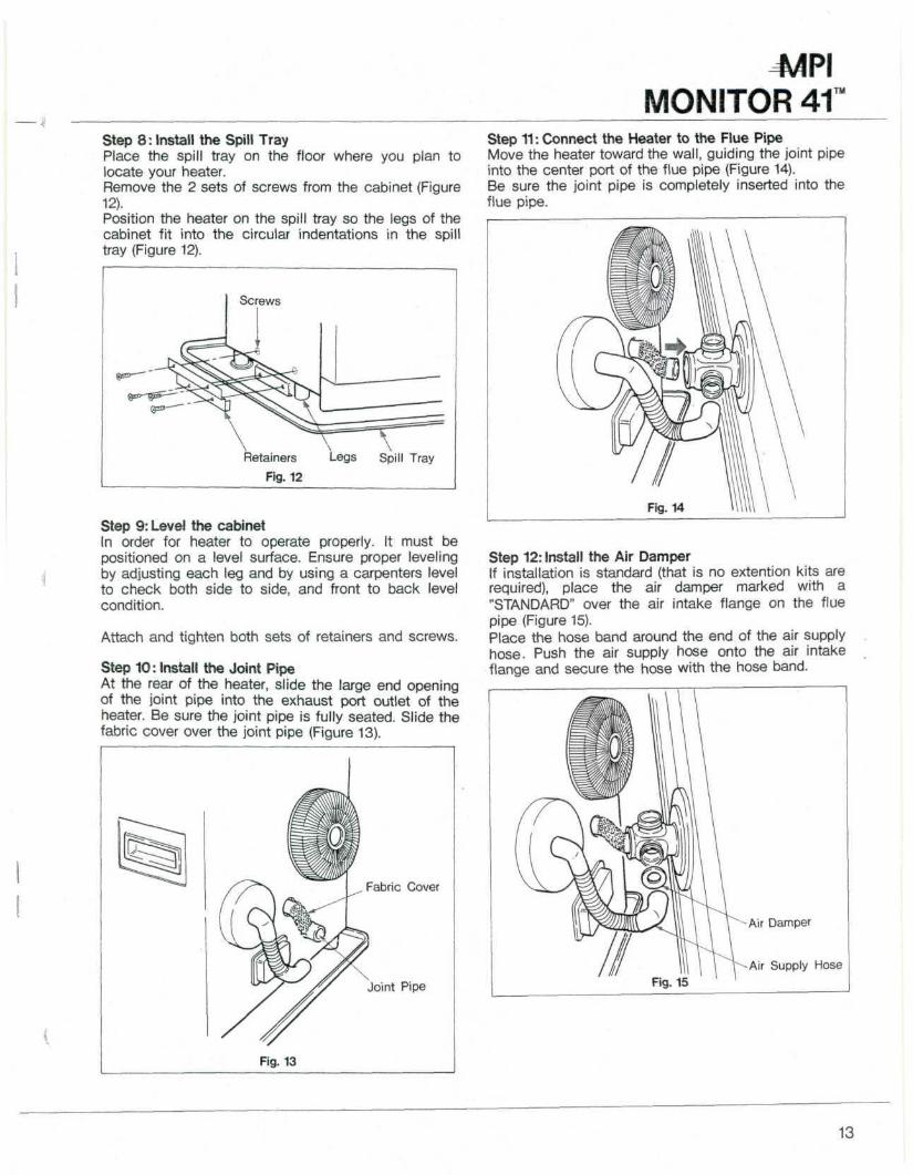
Step 8: Install the Spill TrayPlace the spill tray on the floor where you plan tolocate your heater.Remove the 2 sets of screws from the cabinet (Figure12).Position the heater on the spill tray so the legs of thecabinet fit into the circular indentations in the spilltray (Figure 12).
Step 11: Connect the Heater to the Flue PipeMove the heater toward the wall, guiding the joint pipeinto the center port of the flue pipe (Figure 14).Be sure the joint pipe is completely inserted into theflue pipe.
Screws
Retainers
Fig. 12
Legs Spill Tray
Step 9: Level the cabinetIn order for heater to operate properly. It must bepositioned on a level surface. Ensure proper levelingby adjusting each leg and by using a carpenters levelto check both side to side, and front to back levelcondition.
Attach and tighten both sets of retainers and screws.
Step 10: Install the Joint PipeAt the rear of the heater, slide the large end openingof the joint pipe into the exhaust port outlet of theheater. Be sure the joint pipe is fully seated. Slide thefabric cover over the joint pipe (Figure 13).
Step 12: Install the Air DamperIf installation is standard (that is no extention kits arerequired), place the air damper marked with a"STANDARD" over the air intake flange on the fluepipe (Figure 15).Place the hose band around the end of the air supplyhose. Push the air supply hose onto the air intakeflange and secure the hose with the hose band.
Fabric Cover
Joint Pipe
Fig. 13
13

NOTE:The "STANDARD" damper is to be used withextension kits up to a total overall length of 20inches and a maximum of 3 bends (90° elbow).The "EXTENSION" damper must be used whenextension kit or kits exceed 20 inches.
Step 13: Install the Flue Pipe HolderPlace the ring of the flue pipe holder around the fluepipe. The other side of the holder hooks in a slot di-rectly above the joint pipe at the rear of the heater(See Figure 16).
Step 15: Recheck the HeaterBefore proceeding, check again to be sure there areno flammable materials close to the heater. Check tobe sure the heater is level.Examine the flue pipe to be sure connections are tight.
Flue Pipe Holder
Fig. 16
Step 14: Secure the HeaterInsert the narrow ends of the 2 wall clamps into socketson the rear of the heater.Loosen the adjustment screws and extend the clampsuntil they touch the wall. Fasten the clamps to thewall with 2 #8x% tapping screws.
NOTE: If use of wall clamps is not feasible orpractical, the heater should be secured byscrew to floor through punched hole in spilltray.
14

SECTION E44PI
MONITOR 41FUELING^ WARNING: Use only crystal clear kerosene. Never use gasoline, white gas, camp fuel or other flammable
liquids. Use of such Fuels can result in an explosive fire and cause severe injury.
FUELING OPTIONS AVAILABLEFueling of your Monitor 41 Heating System can beaccomplished in one of 3 ways:1. Wall Mounted Fuel Tank:For small fueling needs.
This system, available from your MPI dealer, isgravity fed and easily installed by anyone handy inmaking home improvements.
2. Gravity Fed Large Capacity External Tank:Practi-cal for large heating needs where bulk delivery ofkerosene is available. This system should be inst-alled by a qualified plumber or fuel supply techni-cian.
3. Large Capacity External Tank with Pump: For largeheating needs where a gravity fed system is notpractical. An electric suction pump, especially des-igned for use with your Monitor 41 heating system,is available from your dealer.
When using a gravity fed tank or pumping system tosupply fuel, the inlet pressure to the heater must notexceed 2.5 psi.
EXTERNAL TANK INSTALLATION- Gravity FedNOTE:External tank installations must comply with the
National Fire Protection Association code NFPA31 or locally applicable codes, such as the 1979Uniform Mechanical Code No. 5-1, that are con-sistent with NFPA 31. Check with your localbuilding official.
To install a large capacity, gravity fed external tank,follow the instructions below, and refer to Figure 17 forone possible installation. Use of a qualified installer isrecommended.• Installation height of the bottom of the fuel tank
should be 16 inches or more above the floor surfaceon which the heater stands. This insures that inletfuel pressure will be sufficient.
• The top of the fuel tank should be no higher than8)4 feet above the floor under the heater. This ins-ures that inlet fuel pressure will not be excessive.
• The horizontal length of piping should not exceed100 feet and should be free of sharp bends or ob-structions.
• Piping should include no inverse U-type bends (toavoid air locks, which could block the fuel supply).
• Only % inch OD copper tubing should be used. Thetubing should be bent carefully to avoid crimping.
• A fuel filter is recommended for use on the fuel linenear the tank, and a shut-off valve should be in-stalled at the tank.
• Flare connections should be used at the nipple con-nection on the heater and at the fuel filter to beinstalled at the tank.
• The fuel tank should be located no closer than 6feet to a source of heat.
• The fuel tank should have an opening for filling onthe top and vent with a weather-proof cap on theside. On some tanks the vent and fill spout use thesame opening.
When using a gravity fed tank to supply fuel, the inletpressure to the heater must not exceed 2.5 psi.
15

-f ^
Outdoor Fuel Tank
Shut-off Valve
NOTE: Fuel tank must be a minimum 3 feet awayfrom flue pipe. Fig. 17
EMPTY FUEL TANKIf at any time during the operation of your heater youfind.• Burner Status indicators are blinking.• No heat.• No flame.
You can assume you are out of fuel.Should this situation occur, take the following steps.
Step 1: Turn the Heater OffPress the Operation Button to put it in the "Off"position.
Step 2: RefuelRefill your fuel tank with kerosene.
Step 3: Turn the Heater OnPress the Operation Button to put it in the "On"position.
16
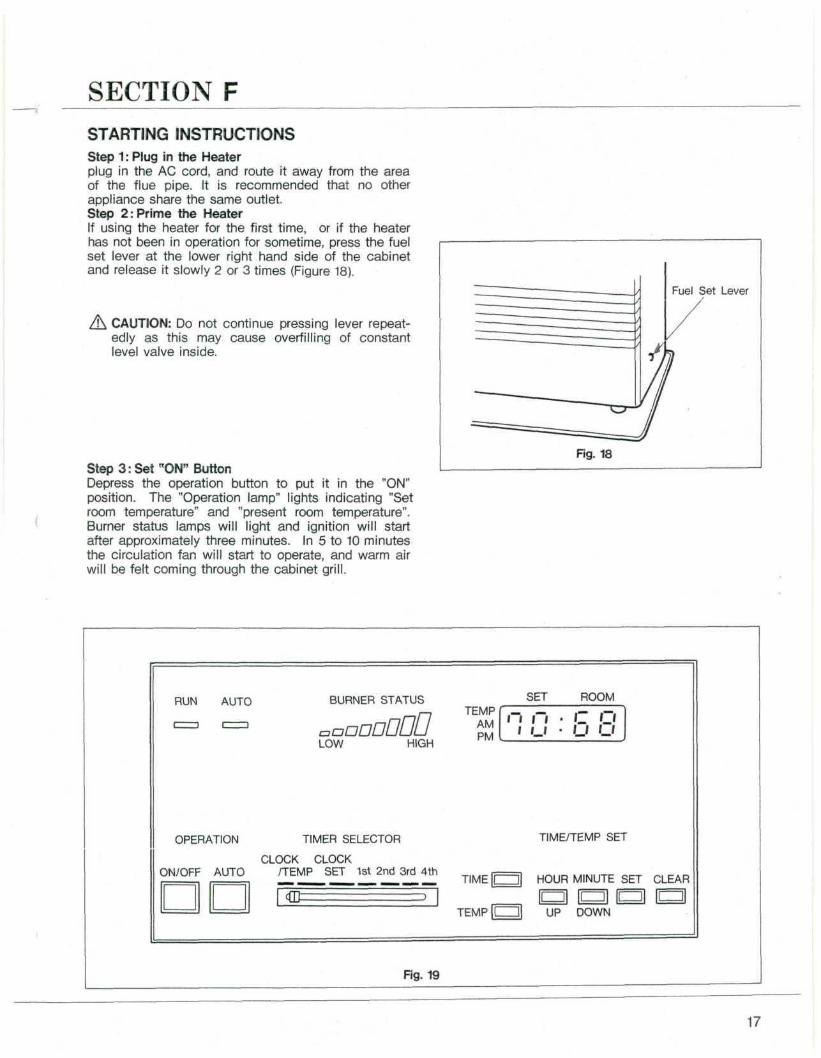
SECTION FSTARTING INSTRUCTIONSStep 1: Plug in the Heaterplug in the AC cord, and route it away from the areaof the flue pipe. It is recommended that no otherappliance share the same outlet.Step 2: Prime the HeaterIf using the heater for the first time, or if the heaterhas not been in operation for sometime, press the fuelset lever at the lower right hand side of the cabinetand release it slowly 2 or 3 times (Figure 18).
, CAUTION: Do not continue pressing lever repeat-edly as this may cause overfilling of constantlevel valve inside.
Step 3: Set "ON" ButtonDepress the operation button to put it in the "ON"position. The "Operation lamp" lights indicating "Setroom temperature" and "present room temperature".Burner status lamps will light and ignition will startafter approximately three minutes. In 5 to 10 minutesthe circulation fan will start to operate, and warm airwill be felt coming through the cabinet grill.
Fuel Set Lever
Fig. 18
RUN AUTO BURNER STATUS SET ROOM
LOW HIGH
TEMPAMPM
n n • c Oi 1.1 • LI '_»
OPERATION
ON/OFF AUTO
TIMER SELECTOR
CLOCK CLOCK/TEMP SET 1st 2nd 3rd 4th— —_—___— — _ TIME
TIME/TEMP SET
HOUR MINUTE SET CLEAR
TEMP UP DOWN
Fig. 19
17

SECTION GADJUSTING ROOM TEMPERATUREPress either the "UP" or "DOWN" button to set thedigital set room temperature indicator to the desiredtemperature, and then press the "SET" button. Afterthe room temperture has stabilized in 1 to 2 hours,adjust the temperature to the desired level.The lights on the control panel will indicate the levelof heater operation — low, medium or high. The heater
BURNER MODE
will automatically change its heat output until thedesired room temperature is reached. While it cycles,you may hear the circulation fan change speed.Depending on the output required to maintain thedesired room temperature, the indicator lights willilluminate in the following pattern:
LIGHT PATTERN
High 8 indicators — OnH.Medium 6 indicators — OnL. Medium 4 indicators — OnLow 2 indicators — OnOff *No lights on
* The heater will shut itself off temporarily when the desired room temperature has been reached and restart automatically whennecessary to maintain room temperature.
NOTE: The heater may display room temperature 4 degrees above set temperature, depending on heater loadconditions, before shutting itself off.
SECTION H SECTION ITURNING OFF THE HEATERTo turn off the heater, press the Operation Button toput it in the "Off" position (Figure 19). The operation-light will go out, and the fuel flow will stop.After turning heater off the fans will continue to rununtil unit has cooled down to the point where the fanswill automatically stop.
RELIGHTING THE HEATERAutomatic controls prevent your heater from relightingafter the Operation Button has been set to "Off" untilheater has cooled.If the Operation Button is put in the "On" positionduring the cooling period, the heater will automaticallyrelight at the end of the period.
18

SECTION J4/1PI
MONITOR 41PROGRAMMING THE HEATERSETTING THE CLOCK
Step 1: Set the Timer SelectorMove the Timer Selector Knob to the "Clock Set" position. The LED indicator in the Display Window will show88:88 at this point.
DISPLAY WINDOW
RUN AUTO BURNER STATUS
LOW
SET ROOM
HIGH
TEMPAMPM
n n • o OLJ l«l ' U '_'
TIMER SELECTOR
OPERATION \ TIMER SELECTOR
CLOCK \ CLOCKON/OFF AUTO /TENP \ SET 1st 2nd 3rd 4th
TIME
TEMP
TIME/TEMP SET
HOUR MINUTE SET CLEAR
UP DOWN
OPERATION BUTTON Rg. 20
Step 2.-Set the HourPress the "Hour" Button until the correct hour (eitherA.M. or P.M.) appears in the window.
Step 3: Set the MinutePress the "Minute" Button until the correct timeappears in the window.Immediately press the "Set" Button.
NOTE: If the "Set" Button is not pressed within 1 minuteafter the time is set, the programming will becancelled.
Step 4: Display the Current TimeTo display the current time, move the Timer SelectorKnob to the "CLOCK/TEMP" position.
19

-' -PROGRAMMING FOR AUTOMATIC HEATER OPERATIONThe monitor 41 Heating System is designed to provideup to 4 times Time/Temperature programming a day.To program the heater for automatic operation, referto Figure 20 and follow the steps below.
Step 1: Set the 1st Time/TemperatureMove the Timer Selector Knob to the "1st" position.Press the TIME Button. Set the 1st desired time bypressing the HOUR and MINUTE Buttons as describedunder "Setting the Clock".
NOTE: Be sure to set the time correctly for either A.M.or P.M.Press the "SET" Button.Press the "TEMP" Button.Set the 1st desired temperature by pressing the"UP and DOWN" Buttons.Press the "SET" Button.
Step 2: Program the Remaining TimesWith the Timer Selector Knob in the appropriatepositions, program the 2nd, 3rd, 4th times as describedabove. Be sure to press the Set Button after each timeis programmed.
Step 3: Activate Automatic OperationTo operate your heater automatically, press the "Auto"Button on the control panel. When you have done this,the "Auto" light will illuminate, confirming that the heateris in the automatic operation mode.
Step 4: Clearing an Automatic SettingShould it become necessary to clear an automaticsetting, slide the Timer Selector Knob to the approp-riate position, and press the "Clear" Button.
IMPORTANT: The heater will not operate in automaticunless the "ON" "OFF" switch is in the"ON" position.
MANUAL OPERATIONWhen there is no further need for automatic operation,or when you wish to override it, press the "AUTO"Button again. Your heater will operate thermostaticallyat the setting you choose, and the clock will continueto operate.
It is important to note that activating manual operationdoes NOT clear the automatic programming. To returnto automatic operation, simply press the "AUTO"Button.
20
SECTION K MONITOR 41™PROTECTIVE FEATURESLOSS OF POWER-AUTOMATIC RESET:
NOTE: If power to the heater is interrupted, a thud-likenoise may be heard in the combustion chamber.This is normal, and should not cause alarm.Once power is restored, your heater will resumeoperation in the MANUAL mode and maintainroom temperature according to the settingtemperature you've selected by using the slideselector for the reset temperature at the lowerright hand side of the cabinet (Figure 21).When the "TIME BUTTON" is pressed or theTimer Selector knob is moved to the "ClockSet" position, the Display Window will show88 : 88 indicating the need to reset the clockand re-program the heater for automaticoperation.
REMARK: In order to display reset temperature,it should be set before the heater is plugged inand energized.New reset temperature selected after pluggedin will take effect only after a power loss.
RESET TEMPERATURE
50 52 54 56 58 60 62 64 66 68 70 72 74 76 78 80
Fig. 21
ELECTRICAL FUSEIn the unlikely event of a failure in the heater'selectrical system, a fuse will "blow" and interrupt thepower. Do not attempt to change the fuse.
Contact your MPI dealer for the name of a trainedand certified service representative in your area.
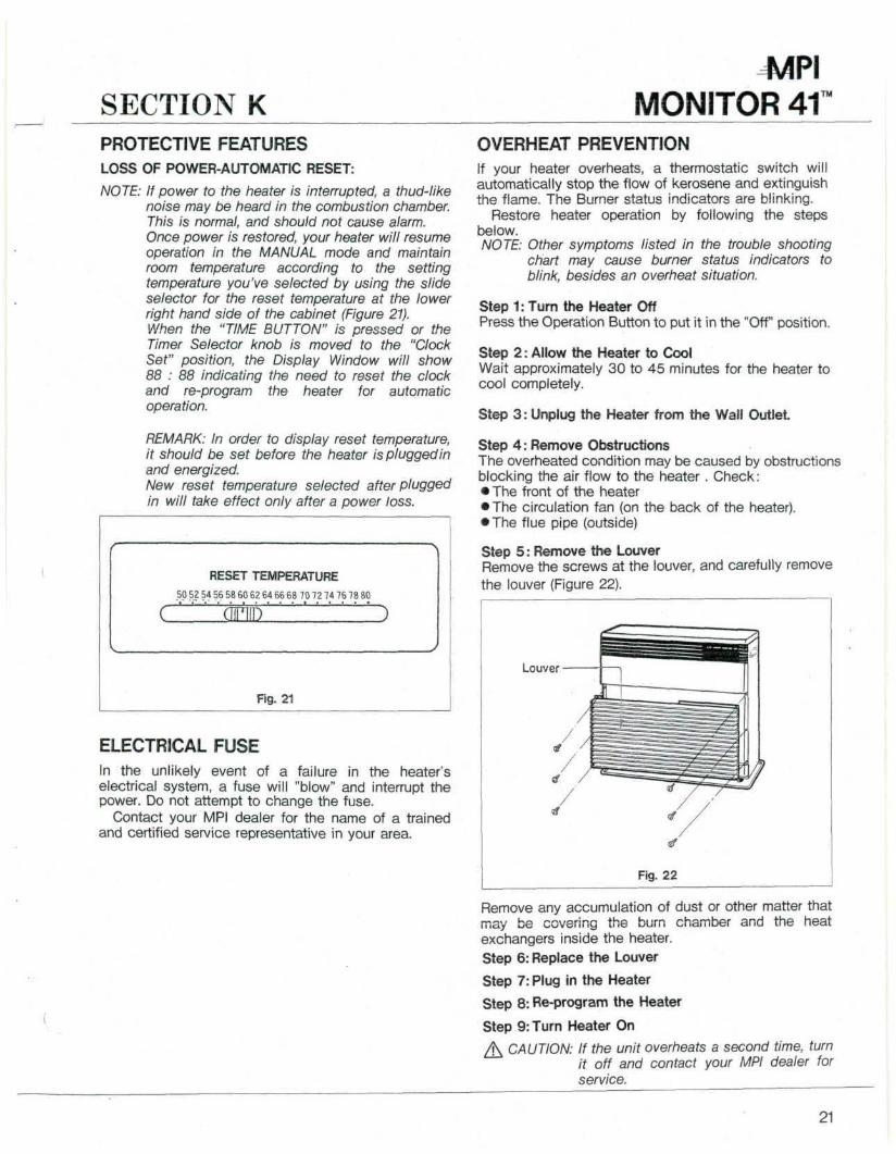
OVERHEAT PREVENTIONIf your heater overheats, a thermostatic switch willautomatically stop the flow of kerosene and extinguishthe flame. The Burner status indicators are blinking.
Restore heater operation by following the stepsbelow.NOTE: Other symptoms listed in the trouble shooting
chart may cause burner status indicators toblink, besides an overheat situation.
Step 1: Turn the Heater OffPress the Operation Button to put it in the "Off" position.
Step 2: Allow the Heater to CoolWait approximately 30 to 45 minutes for the heater tocool completely.
Step 3: Unplug the Heater from the Wall Outlet.
Step 4: Remove ObstructionsThe overheated condition may be caused by obstructionsblocking the air flow to the heater . Check:• The front of the heater• The circulation fan (on the back of the heater).• The flue pipe (outside)
Step 5: Remove the LouverRemove the screws at the louver, and carefully removethe louver (Figure 22).
Louver
Fig. 22
Remove any accumulation of dust or other matter thatmay be covering the burn chamber and the heatexchangers inside the heater.Step 6: Replace the Louver
Step 7: Plug in the Heater
Step 8: Re-program the Heater
Step 9: Turn Heater On
/\ CAUTION: If the unit overheats a second time, turnit off and contact your MPI dealer forservice.
21

SECTION LCARE OF THE HEATERPush operation switch to "OFF" remove the AC Plug from the wall outlet and wait approximately 30 minutes forthe heater to cool before performing any of the following steps.
Step 1: Retrieving Objects from Inside the HeaterShould an object fall inside the heater, through thegrill openings, it must be removed to avoid affectingthe operation of the heater.After allowing the heater to cool, remove the frontcover panel. (See Step 5 of the previous section.)After the object has been removed, replace the frontcover before attempting to re-start the heater.
Step 2: Cleaning the CabinetWhen the cabinet is soiled, wipe it with a damp cloth.Restore the shine with a dry cloth.The use of abrasive household cleaners may dullthe finish.
Step 3: Checking the Flue PipeAt the beginning of each heating season, check theinside of the flue pipe. Foreign matter, spider webs,etc. must be removed.Be sure all fittings and joints are tight.
Step 4: Cleaning the InteriorRemove the Front Cover Panel (as described in Step5 of the previous section), and wipe away dust orother accumulation.Look for signs of fuel leakage around the joint pipeand the bottom of the cabinet. If fuel is detected, wipeit away and if necessary, contact your MPI dealer forany necessary repairs.
Step 5: Cleaning the Blower GuardHeating efficiency will be reduced if the blower guardat rear of the cabinet is blocked with dirt or dust.Blockage also produces a rise in heat that could causethe heater to shut off.Wipe the guard clean at least once a week.
Step 6: Cleaning the Fuel StrainerThe strainer of the fuel constant level valve should becleaned once a year and before storing heater at theend of each season.
Step6-A:Turn knob of the shut-off valve installed at the externaltank to close the fuel line. (See Figure 17).
Step 6-B:To catch the fuel which will drain out, set the drainguide made by cardboard below the strainer cover,with a small container under it. (See Figure 23)
Step 6-C:Loosen the two screws from the strainer cover andremove.
Step 6-D:Remove the strainer and wash with pure kerosene.
Step 6-E:Return the strainer to its original position. Replacestrainer cover and screw to secure.
Step 6-F:Wipe away any spilled kerosene.
Step6-G:Turn the knob of the shut-off valve to open. Check forkerosene leakage.
NOTE: Your Monitor may sometimes require moreservice than that shown above. Should this occurplease contact your Monitor Products, Inc., dealerfor service. A preseason maintenance check upcould be performed by your dealer to ensuretrouble free operation during the season. Askhim for details of his routine maintenanceprogram.
22

4AP\MONITOR 41
™
StrainerCover
Drain Guide Container
Fig. 23
Step 7: Storing the HeaterDuring summer months or long periods when yourheater will not be in operation, take the followingsteps:• Clean off the exterior cabinet with a damp cloth, andbrush or vacuum dust from the grills.• Remove the AC cord from the wall outlet.• Cover the heater to protect it from dust.• DO NOT DISASSEMBLE the heater or extension
kits. Replacement of lost parts is an unnecessaryexpense.
23
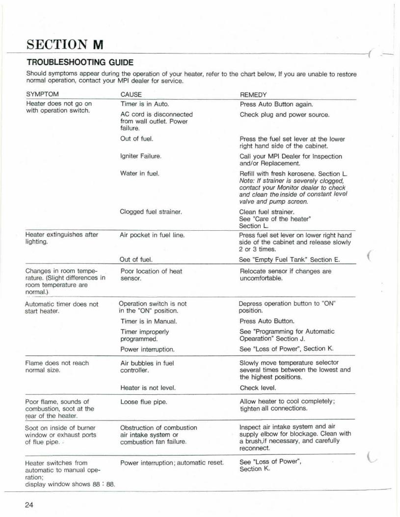
SECTION MTROUBLESHOOTING GUIDEShould symptoms appear during the operation of your heater, refer to the chart below, If you are unable to restorenormal operation, contact your MPI dealer for service.
SYMPTOM CAUSEHeater does not go onwith operation switch.
Timer is in Auto.
AC cord is disconnectedfrom wall outlet. Powerfailure.
Out of fuel.
Igniter Failure.
Water in fuel.
Clogged fuel strainer.
Heater extinguishes afterlighting.
Air pocket in fuel line.
Out of fuel.
Changes in room tempe-rature. (Slight differences inroom temperature arenormal.)
Poor location of heatsensor.
Automatic timer does notstart heater.
Operation switch is notin the "ON" position.
Timer is in Manual.
Timer improperlyprogrammed.
Power interruption.
Flame does not reachnormal size.
Air bubbles in fuelcontroller.
Heater is not level.
Poor flame, sounds ofcombustion, soot at therear of the heater.
Loose flue pipe.
Soot on inside of burnerwindow or exhaust portsof flue pipe.
Obstruction of combustionair intake system orcombustion fan failure.
REMEDYPress Auto Button again.
Check plug and power source.
Press the fuel set lever at the lowerright hand side of the cabinet.
Call your MPI Dealer for Inspectionand/or Replacement.
Refill with fresh kerosene. Section L.Note: If strainer is severely clogged,contact your Monitor dealer to checkand clean the inside of constant levelvalve and pump screen.
Clean fuel strainer.See "Care of the heater"Section L.Press fuel set lever on lower right handside of the cabinet and release slowly2 or 3 times.
See "Empty Fuel Tank" Section E.
Relocate sensor if changes areuncomfortable.
Depress operation button to "ON"position.
Press Auto Button.
See "Programming for AutomaticOpearation" Section J.
See "Loss of Power", Section K.
Slowly move temperature selectorseveral times between the lowest andthe highest positions.
Check level.
Allow heater to cool completely;tighten all connections.
Inspect air intake system and airsupply elbow for blockage. Clean witha brush,if necessary, and carefullyreconnect.
Heater switches fromautomatic to manual ope-ration;display window shows 88
Power interruption; automatic reset. See "Loss of Power",Section K.
88.
24

r Monitor 41™ \fented Heating Systems Limited Warranty nMONITOR PRODUCTS, INC., warrants eachMONITOR 41 vented heating system sold by it tobe free from defects in material and workmanship,under normal use and service, for one year afterthe date of original retail purchase, subject to theterm and conditions stated below. An extendedwarranty period of 36 months is provided forcombustion chamber and heat exchanger. The re-mainder of the unit is subject to the 12 monthswarranty as provided herein.
1. WARRANTOR: This warranty is granted byMONITOR PRODUCTS, INC., P.O. Box 3408,Princeton, New Jersey 08543.
2. PARTIES TO WHOM WARRANTY IS EXTENDED:This warranty shall be extended only to theoriginal retail purchaser.
3. PARTS COVERED: All products and partsmanufactured by or for MONITOR PRODUCTS,INC., except as provided for herein. Replacementparts are warranted only for the balance of theoriginal warranty period.
4. PARTS NOT COVERED: The following parts arenot covered by this warranty: fuel filters, ventingkits, extension kits, fuses.
5. REMEDY: If, within the applicable warrantyperiod, any product or part included in thiswarranty proves to be defective in material and/orworkmanship, then MONITOR PRODUCTS, INC.,shall repair or replace, at its option, the defectiveproduct or part. Service at the point of installation(not including dealer travel time) will be providedat no charge to the customer, but must beperformed by a MONITOR PRODUCTS, INC.,dealer authorized to sell and service theMONITOR 41 vented heating system.
6. PROCEDURE FOR OBTAINING PERFORMANCEUNDER THIS WARRANTY: In order to obtainperformance of the obligations under thiswarranty, the original purchaser must promptly(in no event later than thirty (30) days afterdiscovery of the defect) notify the local MONITORPRODUCTS, INC., dealer authorized to sell andservice the MONITOR 41 vented heating system.Service will be provided during normal businesshours within a reasonable time after the dealerhas been notified of the need for service. If youare unable to locate a local MONITORPRODUCTS, INC., dealer authorized to sell andsen/ice the MONITOR 41. vented heating system,call or write to: SERVICE DEPARTMENT,MONITOR PRODUCTS, INC., P.O. BOX 3408,PRINCETION, NEW JERSEY 08543, 201-329-0900.Any claim made under this warranty must beaccompanied by proof of original purchase datesales invoice or cancelled check showingserial number is satisfactory evidence.
7. SOLE REMEDY: The remedy and liability for anybreach of warranty, express or implied, set forthabove is the sole and exclusive remedy and thelimit of liability for any such breach.
8. EXCLUSIONS AND IMPLIED WARRANTIES: THISWARRANTY DOES NOT EXTEND TO ANYDEFECT DUE TO THE NEGLIGENCE OFOTHERS, FAILURE TO INSTALL, OPERATE ORMAINTAIN THE HEATER IN ACCORDANCEWITH THE INSTALLATION, OPERATION ANDMAINTENANCE INSTRUCTIONS FURNISHEDWITH EACH NEW HEATER, UNREASONABLEUSE, ACCIDENTS, ALTERATIONS, ORDINARYWEAR AND TEAR, THE USE OF UNAUTHO-RIZED OR NON-STANDARDIZED PARTS ORACCESSORIES OR THE USE OF ANY FUELOTHER THAN GOOD QUALITY KEROSENESUCH AS 1K GRADE. ALL IMPLIED WARRAN-TIES, IF ANY, ARISING UNDER STATE LAW INCONNECTION WITH THE SALES BY MONITORPRODUCTS, INC., OF ANY NEW HEATER ARELIMITED IN DURATION TO THE DURATION OFTHIS WRITTEN WARRANTY. THERE ARE NOWARRANTIES, EXPRESS OR IMPLIED, OFMERCHANTABILITY, FITNESS FOR A PARTI-CULAR PURPOSE OR OTHERWISE WHICHEXTEND BEYOND THIS WARRANTY MONITORPRODUCTS, INC., SHALL NOT BE RESPONSI-BLE FOR ANY INCIDENTAL OR CONSEQUEN-TIAL DAMAGES. WHETHER AS A RESULT OFBREACH OF WARRANTY, NEGLIGENCE,STRICT LIABILITY IN TORT OR OTHERWISE.
NOTE: SOME STATES DO NOT ALLOW: (A) LIMI-TATIONS ON HOW LONG AN IMPLIEDWARRANTY LASTS; OR (B) THE EXCLU-SION OR LIMITATION OF INCIDENTAL ORCONSEQUENTIAL DAMAGES, SO THEABOVE LIMITATIONS OR EXCLUSIONSMAY NOT APPLY TO YOU.
9. NO VARIATION OF TERMS: THE PARTIESINTEND THAT THIS WARRANTY BE THEEXCLUSIVE AND FINAL EXPRESSION OFAGREEMENT.No person has the authority to orally, in writingor in any other way vary the terms, conditionsor exclusions, of this warranty or to make anyexpress warranties other than those containedherein.
10. LEGAL RIGHTS: This warranty gives you specificlegal rights and you may also have other rightswhich vary from state to state.
MONITOR PRODUCTS, INC.P.O. BOX 3408
PRINCETON, N.J. 08543
PART NO.1146 PRINTED IN JAPAN COPYRIGHT © 1989 MONITOR PRODUCTS, INC.,