underfloor electric heating system with uncoupling … progress profiles - prodeso heat system...
TRANSCRIPT

Underfloor electric heating system with uncoupling technology.

2 PROGRESS PROFILES - PRODESO HEAT SYSTEM
Underfloor Electric Heating System with Uncoupling Technology.
Underfloor Electric Heating System with uncoupling/vapor management/load distribution and waterproof properties.
Advances in tile manufacturing in the past few decades have improved the quality and choices available to the consumer. New colors, new materials, larger format, thinner tiles and digital printing have all contributed to a steady growth of the use of tile as a surface. When compared to other flooring options such as carpeting and wood floors, tiles are normally preferred because they are easy to clean, resilient, and hygienic. Unfortunately ceramic tile and natural stone, if not installed properly, are subject to cracking, delamination, and are cold to the touch. Use of electrical floor heating can minimize the cold, but submits the tile assembly to additional stress that can lead to cracking and delamination.
Traditionally most electric floor heating, and anti-fracturing membrane manufacturers have recommended covering the electrical heating cables with a self-leveling cement layer or a thin-set layer followed by an uncoupling crack isolating membrane and then finally installing the tiles. This process needlessly increases time, difficulty, thickness, height differentials, weight, and cost of the overall installation.
PROGRESS PROFILES - PRODESO HEAT SYSTEM 3
The patented PRODESO HEAT SYSTEM by Progress Profiles combines the benefit of an underlayment membrane with the comfort and convenience of electrical floor heating. The Prodeso Heat Membrane can be installed over the entire subfloor as an uncoupling, crack isolating and waterproofing membrane. The Prodeso Heat Cable is then installed in the areas where heat is desired. Once the Prodeso Heat Cable is installed you can begin tiling immediately, no waiting is necessary.
PRODESO HEAT MEMBRANE is a polypropylene uncoupling, crack isolation, waterproofing membrane, with rounded square shaped reliefs. These reliefs form channels specially designed to embed and hold the PRODESO HEAT CABLE. PRODESO HEAT MEMBRANE has a polypropylene thermo welded woven underneath to increase the bond between the subfloor and the membrane.
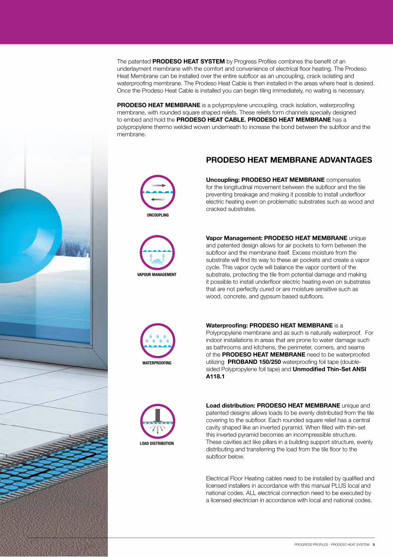
PRODESO HEAT MEMBRANE ADVANTAGES
Uncoupling: PRODESO HEAT MEMBRANE compensates for the longitudinal movement between the subfloor and the tile preventing breakage and making it possible to install underfloor electric heating even on problematic substrates such as wood and cracked substrates.
Vapor Management: PRODESO HEAT MEMBRANE unique and patented design allows for air pockets to form between the subfloor and the membrane itself. Excess moisture from the substrate will find its way to these air pockets and create a vapor cycle. This vapor cycle will balance the vapor content of the substrate, protecting the tile from potential damage and making it possible to install underfloor electric heating even on substrates that are not perfectly cured or are moisture sensitive such as wood, concrete, and gypsum based subfloors.
Waterproofing: PRODESO HEAT MEMBRANE is a Polypropylene membrane and as such is naturally waterproof. For indoor installations in areas that are prone to water damage such as bathrooms and kitchens, the perimeter, corners, and seams of the PRODESO HEAT MEMBRANE need to be waterproofed utilizing PROBAND 150/250 waterproofing foil tape (double-sided Polypropylene foil tape) and Unmodified Thin-Set ANSI A118.1
Load distribution: PRODESO HEAT MEMBRANE unique and patented designs allows loads to be evenly distributed from the tile covering to the subfloor. Each rounded square relief has a central cavity shaped like an inverted pyramid. When filled with thin-set this inverted pyramid becomes an incompressible structure. These cavities act like pillars in a building support structure, evenly distributing and transferring the load from the tile floor to the subfloor below.
Electrical Floor Heating cables need to be installed by qualified and licensed installers in accordance with this manual PLUS local and national codes. ALL electrical connection need to be executed by a licensed electrician in accordance with local and national codes.
UNCOUPLING
WATERPROOFING
VAPOUR MANAGEMENT
LOAD DISTRIBUTION
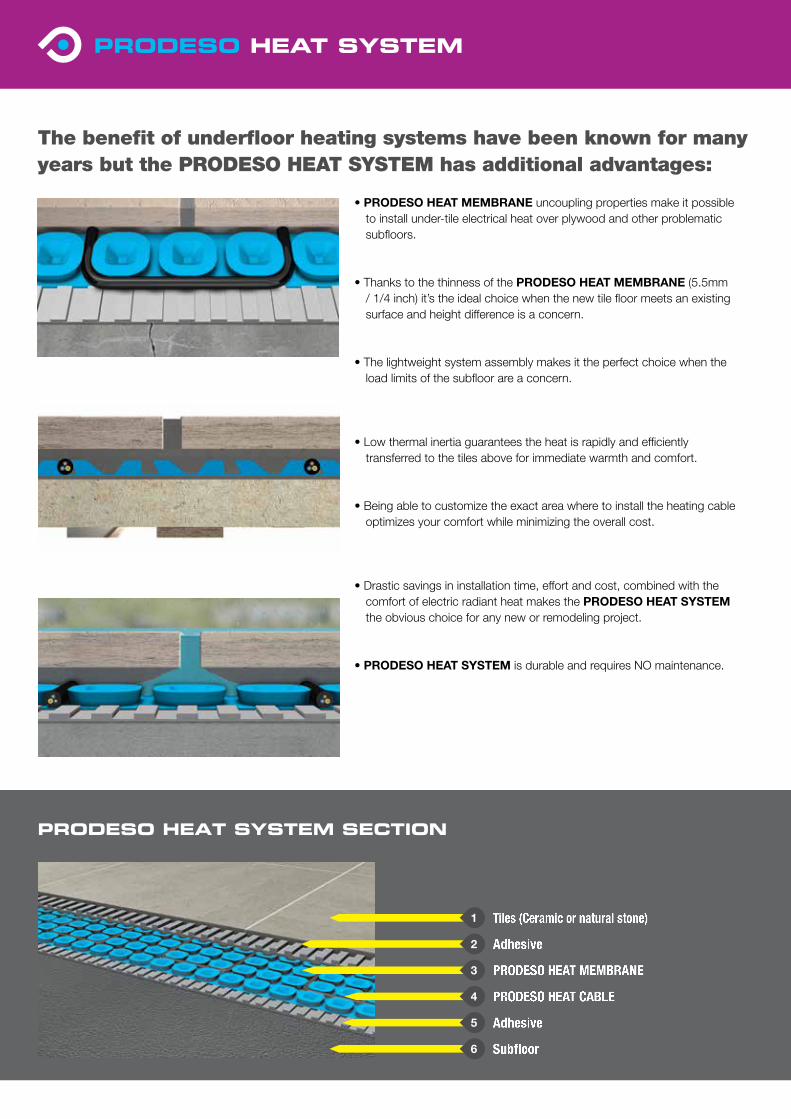
PRODESO HEAT CABLE
Subfloor
Tiles (Ceramic or natural stone)
Adhesive
PRODESO HEAT MEMBRANE
Adhesive
The benefit of underfloor heating systems have been known for many years but the PRODESO HEAT SYSTEM has additional advantages:
• PRODESO HEAT MEMBRANE uncoupling properties make it possibleto install under-tile electrical heat over plywood and other problematicsubfloors.
• Thanks to the thinness of the PRODESO HEAT MEMBRANE (5.5mm/ 1/4 inch) it’s the ideal choice when the new tile floor meets an existingsurface and height difference is a concern.
• The lightweight system assembly makes it the perfect choice when theload limits of the subfloor are a concern.
• Low thermal inertia guarantees the heat is rapidly and efficientlytransferred to the tiles above for immediate warmth and comfort.
• Being able to customize the exact area where to install the heating cableoptimizes your comfort while minimizing the overall cost.
• Drastic savings in installation time, effort and cost, combined with thecomfort of electric radiant heat makes the PRODESO HEAT SYSTEMthe obvious choice for any new or remodeling project.
• PRODESO HEAT SYSTEM is durable and requires NO maintenance.
PRODESO HEAT SYSTEM SECTION
4
6
1
2
3
5
Index
6 PRODESO HEAT SYSTEM Installed Over Wood Subfloor. Indoor tile floor installation of ceramic or natural stone over a structurally sound wood based subfloor.
8 PRODESO HEAT SYSTEM Installed Over Cement Based Subfloor. Indoor tile floor installation of ceramic or natural stone over a structurally sound cement based subfloor.
10 PRODESO HEAT SYSTEM Installed Over Gypsum Based Underlayment. Indoor tile floor installation of ceramic or natural stone over a structurally sound anhydrite based underlayment.
12 PRODESO HEAT SYSTEM Installed Over Pre-existing Vinyl Flooring. Indoor tile floor installation of ceramic or natural stone over an existing structurally sound vinyl floor.
13 Waterproofing
13 Expansion Joints
14 Installation
19 Products
22 Test Log
23 Warranty
6 PROGRESS PROFILES - PRODESO HEAT SYSTEM
Wood
Wood and its derivatives are commonly used in today’s construction. All wood materials expand, contract, bend, and flex with changes in temperature, humidity, and load in the surrounding environment. These deformations can be seasonal or due to an isolated incident such as a plumbing accident, and will naturally occur over the life of a building structure.
PRODESO HEAT SYSTEM properties provide a solution for these challenges.
PRODESO HEAT MEMBRANE will compensate for relative longitudinal movement between theSub-floor and the tiles eliminating the major cause of tile cracking and delamination making it possible to install underfloor electric heating on wood substrates. PRODESO HEAT MEMBRANE eliminates the need for the second layer of Plywood with the exception of Natural Stone tile installations.
Wood is particular sensitive to relative moisture changes in their environment. PRODESO HEAT MEMBRANE unique and patented design allows for air pockets to form between the subfloor and the membrane itself. These air pockets allow for a vapor cycle to form and balance the vapor content of the subfloor assembly, increasing the mechanical and structural property of the wood subfloor.
Wood structures are particularly sensitive to variation in humidity in their environment. PRODESO HEAT MEMBRANE is made of polypropylene, a completely waterproof substance, that will protect the wood subfloor from water damages to ensure a long lasting installation. For areas prone to flood please follow the waterproofing instructions on page 17.
PRODESO HEAT MEMBRANE unique and patented designs allows loads to be evenly distributed from the tile covering to the subfloor. Each rounded square relief has a central cavity shaped like an inverted pyramid. When filled with thin-set this inverted pyramid becomes an incompressible structure. These cavities act like pillars in a building support structure, evenly distributing and transferring the load from the tile floor to the subfloor below.
PRODESO HEAT MEMBRANEThe uncoupling membrane is laid directly over the entire surface intended for tile installation. The heating cable is then installed in the areas where heat is desired using the channels formed between the rounded square reliefs. It’s NOT necessary to use self-leveling cement to cover and protect the wire before starting tile installation. This results in significant savings of material, time, cost and overall weight. Tile installation can start immediately after installing the heated cable.
UNCOUPLING
WATERPROOFING
VAPOR MANAGEMENT
LOAD DISTRIBUTION
Wood subfloor considerationsand installation details
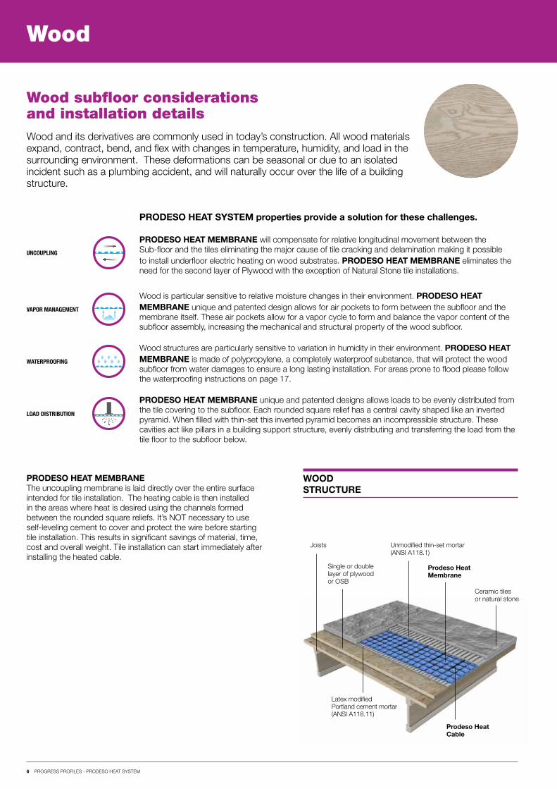
Ceramic tiles or natural stone
Joists Unmodified thin-set mortar(ANSI A118.1)
Single or double layer of plywood or OSB
Latex modifiedPortland cement mortar (ANSI A118.11)
Prodeso HeatMembrane
Prodeso HeatCable
WOODSTRUCTURE
7 PROGRESS PROFILES - PRODESO HEAT SYSTEM
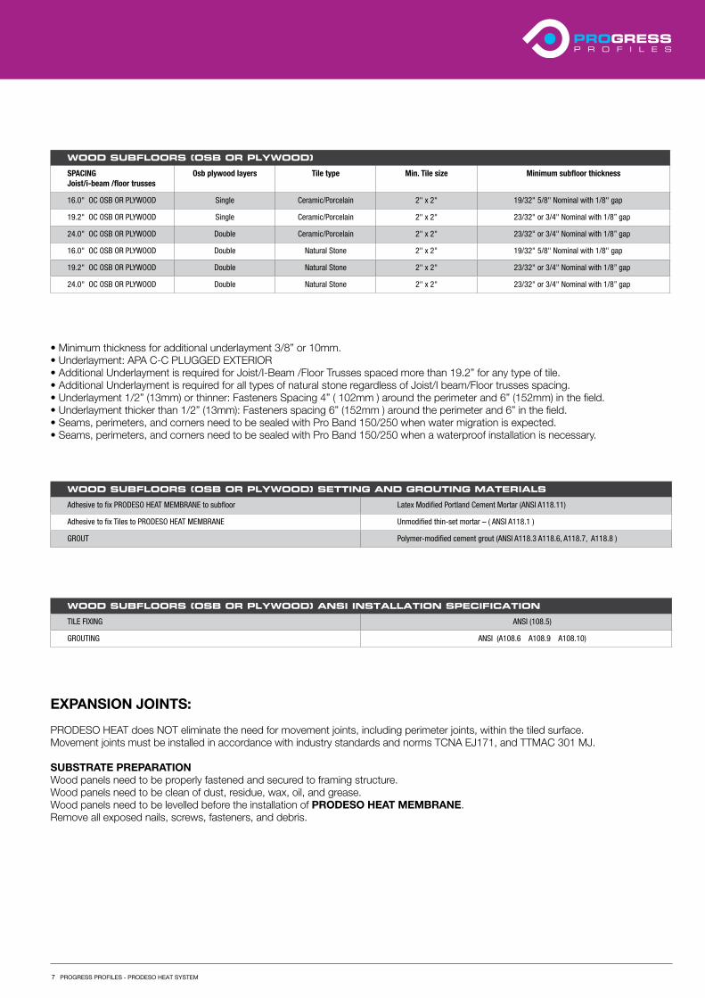
• Minimum thickness for additional underlayment 3/8” or 10mm.• Underlayment: APA C-C PLUGGED EXTERIOR• Additional Underlayment is required for Joist/I-Beam /Floor Trusses spaced more than 19.2” for any type of tile.• Additional Underlayment is required for all types of natural stone regardless of Joist/I beam/Floor trusses spacing.• Underlayment 1/2” (13mm) or thinner: Fasteners Spacing 4” ( 102mm ) around the perimeter and 6” (152mm) in the field.• Underlayment thicker than 1/2” (13mm): Fasteners spacing 6” (152mm ) around the perimeter and 6” in the field.• Seams, perimeters, and corners need to be sealed with Pro Band 150/250 when water migration is expected.• Seams, perimeters, and corners need to be sealed with Pro Band 150/250 when a waterproof installation is necessary.
EXPANSION JOINTS:
PRODESO HEAT does NOT eliminate the need for movement joints, including perimeter joints, within the tiled surface.Movement joints must be installed in accordance with industry standards and norms TCNA EJ171, and TTMAC 301 MJ.
SUBSTRATE PREPARATIONWood panels need to be properly fastened and secured to framing structure.Wood panels need to be clean of dust, residue, wax, oil, and grease.Wood panels need to be levelled before the installation of PRODESO HEAT MEMBRANE.Remove all exposed nails, screws, fasteners, and debris.
WOOD SUBFLOORS (OSB OR PLYWOOD)
SPACING Joist/i-beam /floor trusses
Osb plywood layers Tile type Min. Tile size Minimum subfloor thickness
16.0" OC OSB OR PLYWOOD Single Ceramic/Porcelain 2" x 2" 19/32" 5/8" Nominal with 1/8" gap
19.2" OC OSB OR PLYWOOD Single Ceramic/Porcelain 2" x 2" 23/32" or 3/4" Nominal with 1/8” gap
24.0" OC OSB OR PLYWOOD Double Ceramic/Porcelain 2" x 2" 23/32" or 3/4" Nominal with 1/8” gap
16.0" OC OSB OR PLYWOOD Double Natural Stone 2" x 2" 19/32" 5/8" Nominal with 1/8" gap
19.2" OC OSB OR PLYWOOD Double Natural Stone 2" x 2" 23/32" or 3/4" Nominal with 1/8” gap
24.0" OC OSB OR PLYWOOD Double Natural Stone 2" x 2" 23/32" or 3/4" Nominal with 1/8” gap
WOOD SUBFLOORS (OSB OR PLYWOOD) SETTING AND GROUTING MATERIALS
Adhesive to fix PRODESO HEAT MEMBRANE to subfloor Latex Modified Portland Cement Mortar (ANSI A118.11)
Adhesive to fix Tiles to PRODESO HEAT MEMBRANE Unmodified thin-set mortar – ( ANSI A118.1 )
GROUT Polymer-modified cement grout (ANSI A118.3 A118.6, A118.7, A118.8 )
WOOD SUBFLOORS (OSB OR PLYWOOD) ANSI INSTALLATION SPECIFICATION
TILE FIXING ANSI (108.5)
GROUTING ANSI (A108.6 A108.9 A108.10)
8 PROGRESS PROFILES - PRODESO HEAT SYSTEM
Cement
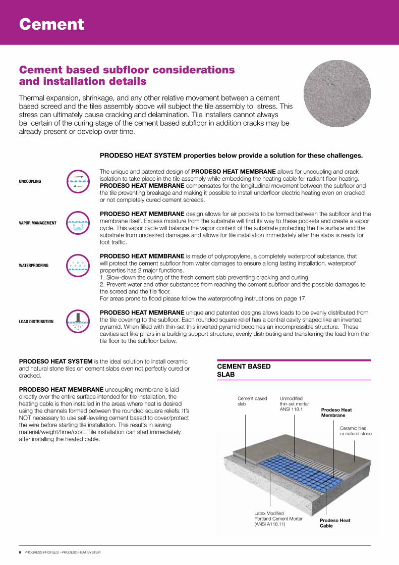
Thermal expansion, shrinkage, and any other relative movement between a cement based screed and the tiles assembly above will subject the tile assembly to stress. This stress can ultimately cause cracking and delamination. Tile installers cannot always be certain of the curing stage of the cement based subfloor in addition cracks may be already present or develop over time.
Cement based subfloor considerations and installation details
Cement based slab
Unmodified thin-set mortar ANSI 118.1
Latex Modified Portland Cement Mortar (ANSI A118.11)
Prodeso HeatMembrane
Prodeso HeatCable
The unique and patented design of PRODESO HEAT MEMBRANE allows for uncoupling and crack isolation to take place in the tile assembly while embedding the heating cable for radiant floor heating.PRODESO HEAT MEMBRANE compensates for the longitudinal movement between the subfloor and the tile preventing breakage and making it possible to install underfloor electric heating even on cracked or not completely cured cement screeds.
PRODESO HEAT MEMBRANE design allows for air pockets to be formed between the subfloor and the membrane itself. Excess moisture from the substrate will find its way to these pockets and create a vapor cycle. This vapor cycle will balance the vapor content of the substrate protecting the tile surface and the substrate from undesired damages and allows for tile installation immediately after the slabs is ready for foot traffic.
PRODESO HEAT MEMBRANE is made of polypropylene, a completely waterproof substance, that will protect the cement subfloor from water damages to ensure a long lasting installation. waterproof properties has 2 major functions.1. Slow-down the curing of the fresh cement slab preventing cracking and curling.2. Prevent water and other substances from reaching the cement subfloor and the possible damages to the screed and the tile floor.For areas prone to flood please follow the waterproofing instructions on page 17.
PRODESO HEAT MEMBRANE unique and patented designs allows loads to be evenly distributed from the tile covering to the subfloor. Each rounded square relief has a central cavity shaped like an inverted pyramid. When filled with thin-set this inverted pyramid becomes an incompressible structure. These cavities act like pillars in a building support structure, evenly distributing and transferring the load from the tile floor to the subfloor below.
UNCOUPLING
WATERPROOFING
VAPOR MANAGEMENT
LOAD DISTRIBUTION
CEMENT BASED SLAB
PRODESO HEAT SYSTEM is the ideal solution to install ceramic and natural stone tiles on cement slabs even not perfectly cured or cracked.
PRODESO HEAT MEMBRANE uncoupling membrane is laid directly over the entire surface intended for tile installation, the heating cable is then installed in the areas where heat is desired using the channels formed between the rounded square reliefs. It’s NOT necessary to use self-leveling cement based to cover/protect the wire before starting tile installation. This results in saving material/weight/time/cost. Tile installation can start immediately after installing the heated cable.
Ceramic tiles or natural stone
PRODESO HEAT SYSTEM properties below provide a solution for these challenges.
9 PROGRESS PROFILES - PRODESO HEAT SYSTEM
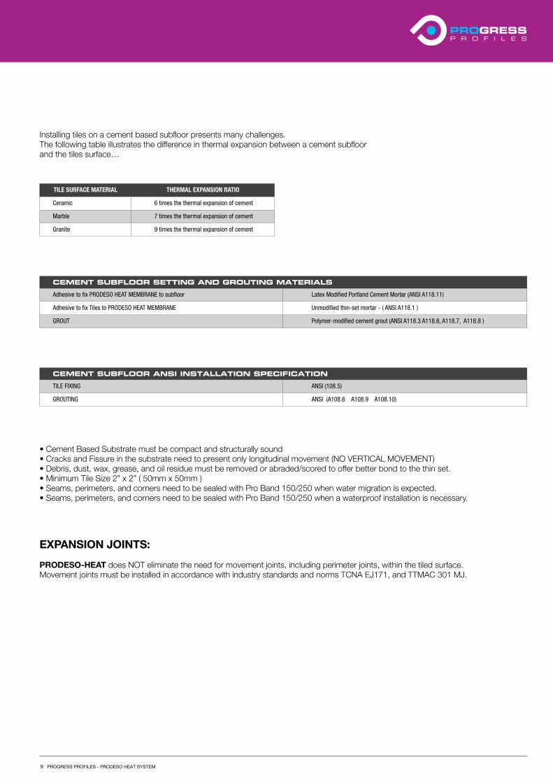
Installing tiles on a cement based subfloor presents many challenges.The following table illustrates the difference in thermal expansion between a cement subfloorand the tiles surface…
TILE SURFACE MATERIAL THERMAL EXPANSION RATIO
Ceramic 6 times the thermal expansion of cement
Marble 7 times the thermal expansion of cement
Granite 9 times the thermal expansion of cement
CEMENT SUBFLOOR SETTING AND GROUTING MATERIALS
Adhesive to fix PRODESO HEAT MEMBRANE to subfloor Latex Modified Portland Cement Mortar (ANSI A118.11)
Adhesive to fix Tiles to PRODESO HEAT MEMBRANE Unmodified thin-set mortar - ( ANSI A118.1 )
GROUT Polymer-modified cement grout (ANSI A118.3 A118.6, A118.7, A118.8 )
CEMENT SUBFLOOR ANSI INSTALLATION SPECIFICATION
TILE FIXING ANSI (108.5)
GROUTING ANSI (A108.6 A108.9 A108.10)
• Cement Based Substrate must be compact and structurally sound• Cracks and Fissure in the substrate need to present only longitudinal movement (NO VERTICAL MOVEMENT)• Debris, dust, wax, grease, and oil residue must be removed or abraded/scored to offer better bond to the thin set.• Minimum Tile Size 2” x 2” ( 50mm x 50mm )• Seams, perimeters, and corners need to be sealed with Pro Band 150/250 when water migration is expected.• Seams, perimeters, and corners need to be sealed with Pro Band 150/250 when a waterproof installation is necessary.
EXPANSION JOINTS:
PRODESO-HEAT does NOT eliminate the need for movement joints, including perimeter joints, within the tiled surface.Movement joints must be installed in accordance with industry standards and norms TCNA EJ171, and TTMAC 301 MJ.
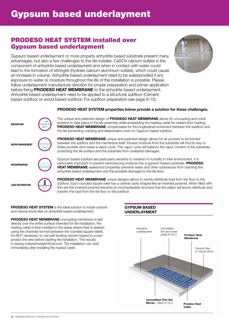
Anhydrite underlayment
Unmodified thin-set mortar(ANSI A118.1)
Unmodified Thin-Set Mortar ( ANSI A118.1)
Prodeso HeatMembrane
Prodeso HeatCable
Ceramic tiles or natural stone
10 PROGRESS PROFILES - PRODESO HEAT SYSTEM
Gypsum based underlayment
Gypsum based underlayment or more properly anhydrite based substrate present many advantages, but also a few challenges to the tile installer. CaSO4 calcium sulfate is the component of anhydrite based underlayment and when in contact with water could lead to the formation of ettringite (hydrate calcium aluminium sulfate), which could cause an increase in volume. Anhydrite based underlayment need to be waterproofed if any exposure to water or moisture throughout the life of the installation is possible. Please follow underlayment manufacture direction for proper preparation and primer application before fixing PRODESO HEAT MEMBRANE to the anhydrite based underlayment. Anhydrite based underlayment need to be applied to a structural subfloor (Cement based subfloor or wood based subfloor. For subfloor preperation see page 9-10).
PRODESO HEAT SYSTEM installed over Gypsum based underlayment
The unique and patented design of PRODESO HEAT MEMBRANE allows for uncoupling and crack isolation to take place in the tile assembly while embedding the heating cable for radiant floor heating.PRODESO HEAT MEMBRANE compensates for the longitudinal movement between the subfloor and the tile preventing cracking and delamination even on Gypsum based subfloor.
PRODESO HEAT MEMBRANE unique and patented design allows for air pockets to be formed between the subfloor and the membrane itself. Excess moisture from the substrate will find its way to these pockets and create a vapor cycle. This vapor cycle will balance the vapor content of the substrate protecting the tile surface and the substrate from undesired damages.
Gypsum based subfloor are particularly sensitive to variation in humidity in their environment. It is particularly important to prevent reintroducing moisture into a gypsum based substrate. PRODESO HEAT MEMBRANE waterproof properties prevents water and other substances from reaching the anhydrite based underlayment and the possible damages to the tile floor.
PRODESO HEAT MEMBRANE unique designs allows to evenly distribute load from the floor to the subfloor. Each rounded square relief has a central cavity shaped like an inverted pyramid. When filled with thin set this inverted pyramid become an incompressible structure that like pillars will evenly distribute and transfer the load from the tile floor to the subfloor.
UNCOUPLING
WATERPROOFING
VAPOR MANAGEMENT
LOAD DISTRIBUTION
PRODESO HEAT SYSTEM is the ideal solution to install ceramic and natural stone tiles on anhydrite based underlayment.
PRODESO HEAT MEMBRANE uncoupling membrane is laid directly over the entire surface intended for tile installation, the heating cable is then installed in the areas where heat is desired using the channels formed between the rounded square reliefs. It’s NOT necessary to use self-leveling cement based to cover/ protect the wire before starting tile installation. This results in saving material/weight/time/cost. Tile installation can start immediately after installing the heated cable.
GYPSUM BASED UNDERLAYMENT
PRODESO HEAT SYSTEM properties below provide a solution for these challenges.
11 PROGRESS PROFILES - PRODESO HEAT SYSTEM
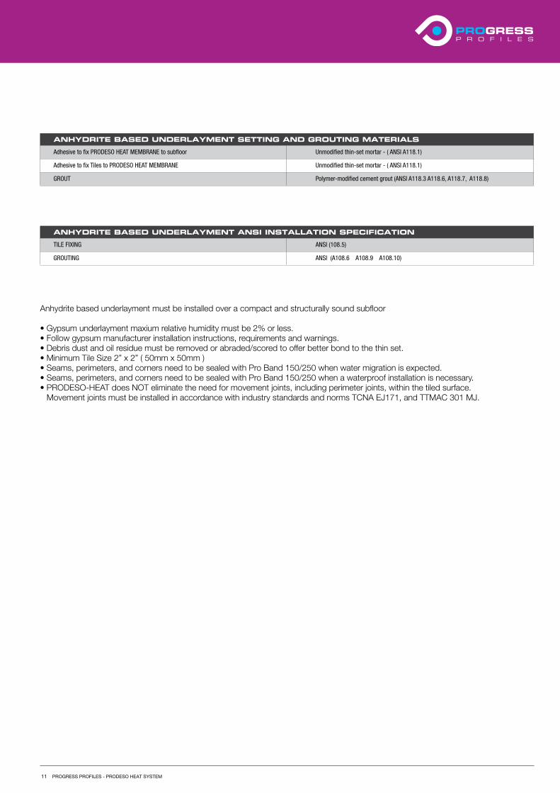
ANHYDRITE BASED UNDERLAYMENT SETTING AND GROUTING MATERIALS
Adhesive to fix PRODESO HEAT MEMBRANE to subfloor Unmodified thin-set mortar - ( ANSI A118.1)
Adhesive to fix Tiles to PRODESO HEAT MEMBRANE Unmodified thin-set mortar - ( ANSI A118.1)
GROUT Polymer-modified cement grout (ANSI A118.3 A118.6, A118.7, A118.8)
ANHYDRITE BASED UNDERLAYMENT ANSI INSTALLATION SPECIFICATION
TILE FIXING ANSI (108.5)
GROUTING ANSI (A108.6 A108.9 A108.10)
Anhydrite based underlayment must be installed over a compact and structurally sound subfloor
• Gypsum underlayment maxium relative humidity must be 2% or less.• Follow gypsum manufacturer installation instructions, requirements and warnings.• Debris dust and oil residue must be removed or abraded/scored to offer better bond to the thin set.• Minimum Tile Size 2” x 2” ( 50mm x 50mm )• Seams, perimeters, and corners need to be sealed with Pro Band 150/250 when water migration is expected.• Seams, perimeters, and corners need to be sealed with Pro Band 150/250 when a waterproof installation is necessary.• PRODESO-HEAT does NOT eliminate the need for movement joints, including perimeter joints, within the tiled surface.
Movement joints must be installed in accordance with industry standards and norms TCNA EJ171, and TTMAC 301 MJ.
Ceramic tiles or natural stone
Joists Unmodified thin-set mortar(ANSI A118.1)
Vinyl Flooring
Fast Setting Latex Modified thin set (ANSI A118.4 - A118.15)
Prodeso HeatMembrane
Prodeso HeatCable
12 PROGRESS PROFILES - PRODESO HEAT SYSTEM
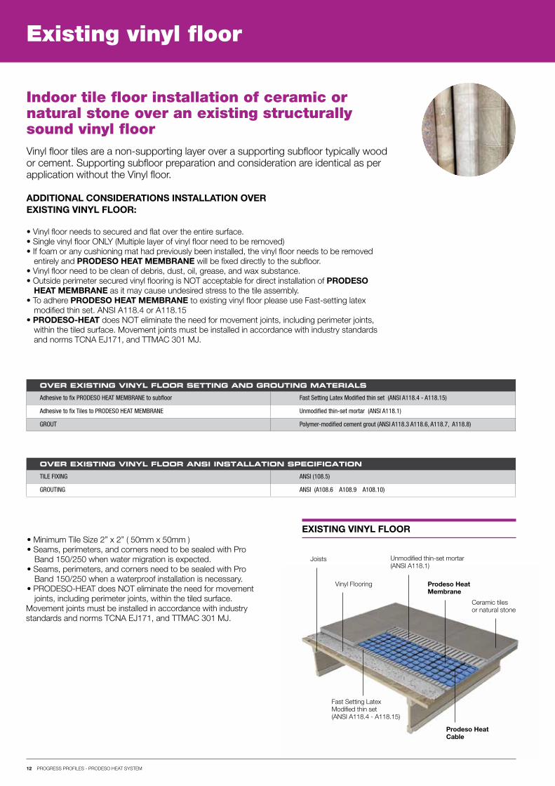
Existing vinyl floor
Vinyl floor tiles are a non-supporting layer over a supporting subfloor typically wood or cement. Supporting subfloor preparation and consideration are identical as per application without the Vinyl floor.
ADDITIONAL CONSIDERATIONS INSTALLATION OVER EXISTING VINYL FLOOR:
Indoor tile floor installation of ceramic or natural stone over an existing structurally sound vinyl floor
• Vinyl floor needs to secured and flat over the entire surface.• Single vinyl floor ONLY (Multiple layer of vinyl floor need to be removed)• If foam or any cushioning mat had previously been installed, the vinyl floor needs to be removed
entirely and PRODESO HEAT MEMBRANE will be fixed directly to the subfloor.• Vinyl floor need to be clean of debris, dust, oil, grease, and wax substance.• Outside perimeter secured vinyl flooring is NOT acceptable for direct installation of PRODESO
HEAT MEMBRANE as it may cause undesired stress to the tile assembly.• To adhere PRODESO HEAT MEMBRANE to existing vinyl floor please use Fast-setting latex
modified thin set. ANSI A118.4 or A118.15• PRODESO-HEAT does NOT eliminate the need for movement joints, including perimeter joints,
within the tiled surface. Movement joints must be installed in accordance with industry standardsand norms TCNA EJ171, and TTMAC 301 MJ.
OVER EXISTING VINYL FLOOR SETTING AND GROUTING MATERIALS
Adhesive to fix PRODESO HEAT MEMBRANE to subfloor Fast Setting Latex Modified thin set (ANSI A118.4 - A118.15)
Adhesive to fix Tiles to PRODESO HEAT MEMBRANE Unmodified thin-set mortar (ANSI A118.1)
GROUT Polymer-modified cement grout (ANSI A118.3 A118.6, A118.7, A118.8)
OVER EXISTING VINYL FLOOR ANSI INSTALLATION SPECIFICATION
TILE FIXING ANSI (108.5)
GROUTING ANSI (A108.6 A108.9 A108.10)
• Minimum Tile Size 2” x 2” ( 50mm x 50mm )• Seams, perimeters, and corners need to be sealed with Pro
Band 150/250 when water migration is expected.• Seams, perimeters, and corners need to be sealed with Pro
Band 150/250 when a waterproof installation is necessary.• PRODESO-HEAT does NOT eliminate the need for movement
joints, including perimeter joints, within the tiled surface.Movement joints must be installed in accordance with industry standards and norms TCNA EJ171, and TTMAC 301 MJ.
EXISTING VINYL FLOOR
13 PROGRESS PROFILES - PRODESO HEAT SYSTEM
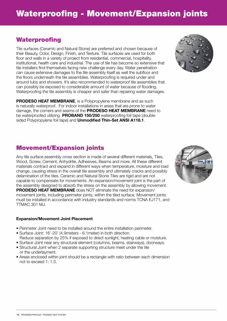
Waterproofing - Movement/Expansion joints
Tile surfaces (Ceramic and Natural Stone) are preferred and chosen because of their Beauty, Color, Design, Finish, and Texture. Tile surfaces are used for both floor and walls in a variety of project from residential, commercial, hospitality, institutional, health care and industrial. The use of tile has become so extensive that tile installers find themselves facing new challenge every day. Water penetration can cause extensive damages to the tile assembly itself as well the subfloor and the floors underneath the tile assemblies. Waterproofing is required under and around tubs and showers. It’s also recommended to waterproof tile assemblies that can possibly be exposed to considerable amount of water because of flooding. Waterproofing the tile assembly is cheaper and safer than repairing water damages.
PRODESO HEAT MEMBRANE, is a Polypropylene membrane and as such is naturally waterproof. For indoor installations in areas that are prone to water damage, the corners and seams of the PRODESO HEAT MEMBRANE need to be waterproofed utilizing PROBAND 150/250 waterproofing foil tape (double-sided Polypropylene foil tape) and Unmodified Thin-Set ANSI A118.1.
Any tile surface assembly cross section is made of several different materials, Tiles, Wood, Screw, Cement, Anhydrite, Adhesives, Beams and more. All these different materials contract and expand in different ways when temperature, moisture and load change, causing stress in the overall tile assembly and ultimately cracks and possibly delamination of the tiles. Ceramic and Natural Stone Tiles are rigid and are not capable to compensate for movements. An expansion/movement joint is the part of the assembly designed to absorb the stress on the assembly by allowing movement. PRODESO HEAT MEMBRANE does NOT eliminate the need for expansion/movement joints, including perimeter joints, within the tiled surface. Movement joints must be installed in accordance with industry standards and norms TCNA EJ171, and TTMAC 301 MJ.
Expansion/Movement Joint Placement
• Perimeter Joint need to be installed around the entire installation perimeter.• Surface Joint: 16’-20’ (4.9meters - 6.1meter) in both direction.
Reduce separation by 25% if exposed to direct sunlight, heating cable or moisture.• Surface Joint near any structural element (columns, beams, stairways), doorways.• Structural Joint when 2 separate supporting structure meet under the tile
or the underlayment.• Areas enclosed within joint should be a rectangle with ratio between each dimension
not to exceed 1: 1.5.
Waterproofing
Movement/Expansion joints
1
4
2 3
5
14 PROGRESS PROFILES - PRODESO HEAT SYSTEM
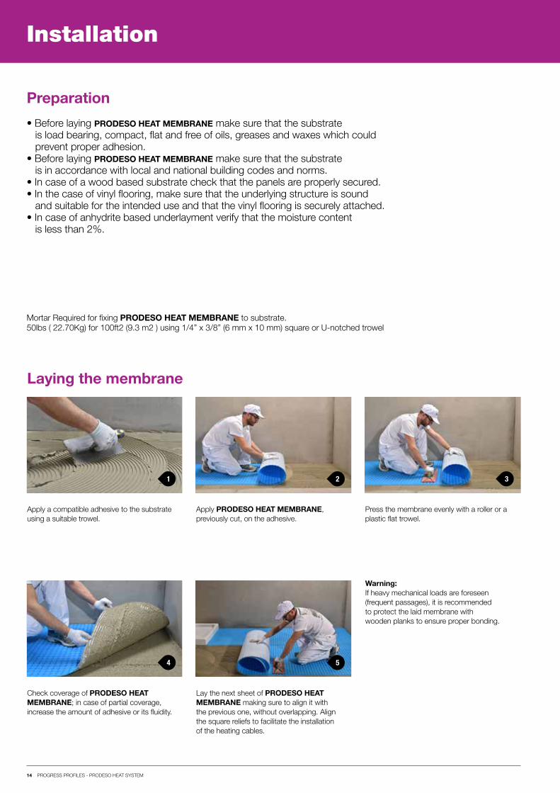
Installation
Preparation
• Before laying PRODESO HEAT MEMBRANE make sure that the substrateis load bearing, compact, flat and free of oils, greases and waxes which couldprevent proper adhesion.
• Before laying PRODESO HEAT MEMBRANE make sure that the substrateis in accordance with local and national building codes and norms.
• In case of a wood based substrate check that the panels are properly secured.• In the case of vinyl flooring, make sure that the underlying structure is sound
and suitable for the intended use and that the vinyl flooring is securely attached.• In case of anhydrite based underlayment verify that the moisture content
is less than 2%.
Mortar Required for fixing PRODESO HEAT MEMBRANE to substrate.50lbs ( 22.70Kg) for 100ft2 (9.3 m2 ) using 1/4” x 3/8” (6 mm x 10 mm) square or U-notched trowel
Apply a compatible adhesive to the substrate using a suitable trowel.
Lay the next sheet of PRODESO HEAT MEMBRANE making sure to align it with the previous one, without overlapping. Align the square reliefs to facilitate the installation of the heating cables.
Apply PRODESO HEAT MEMBRANE, previously cut, on the adhesive.
Press the membrane evenly with a roller or a plastic flat trowel.
Check coverage of PRODESO HEAT MEMBRANE; in case of partial coverage, increase the amount of adhesive or its fluidity.
Warning:If heavy mechanical loads are foreseen (frequent passages), it is recommended to protect the laid membrane with wooden planks to ensure proper bonding.
Laying the membrane

1 2 3
4 5 6
15 PROGRESS PROFILES - PRODESO HEAT SYSTEM
Installation
Laying the heating cables
Install the floor temperature sensors exactlyin the center between two cables and at adistance of at least 2 ft (60cm) from the wall. Do not cross sensor cables with heating cables.It is recommended to install a second temperature sensor as a backup in case the primary fails throughout the life of the installation.Record the exact position of the sensors.
After installation of heating cables, repeat allprevious tests and record the values obtained in the “Test Log” (page 22).
NEVER cross heating cablesNEVER exceed 15 watts per square foot
Perform floor temperature sensor test to ensure functionality.
Warnings:
• During installation of the heating cables,leave space for the placement of the floortemperature sensors.
• The maximum length of a straight line runfor each individual path is 3 m - 9 ft.
• The cable must be installed at a minimumdistance of 20 cm - 8 in from other heatsources (fireplaces) and 15 cm - 6 in fromwaist drains.
Before removing the cable from the spool, youneed to conduct the resistance, continuity, insulation resistance tests. These first set of tests are required, please write the values obtained in the “Test Log” (page 22).
Insert the cold heating cable and floortemperature sensors inside two seperate corrugated pipes from the base of the wall to the thermostat electrical box.
Insert the heating cable in the membraneusing minimum spacing suggested by cablemanufacturer. Two reliefs spacing will result in a heating cablespacing of 2 1/2” (63.5 mm)Three reliefs spacing will result in a heating cablespacing of 3 3/4” (95 mm)Smaller spacing would cause overheating, which may damage the assembly structure.
Warnings: Do not run the heating cables under walls, cabinets, furniture, and appliances.
1 2
5 6
7
3
4
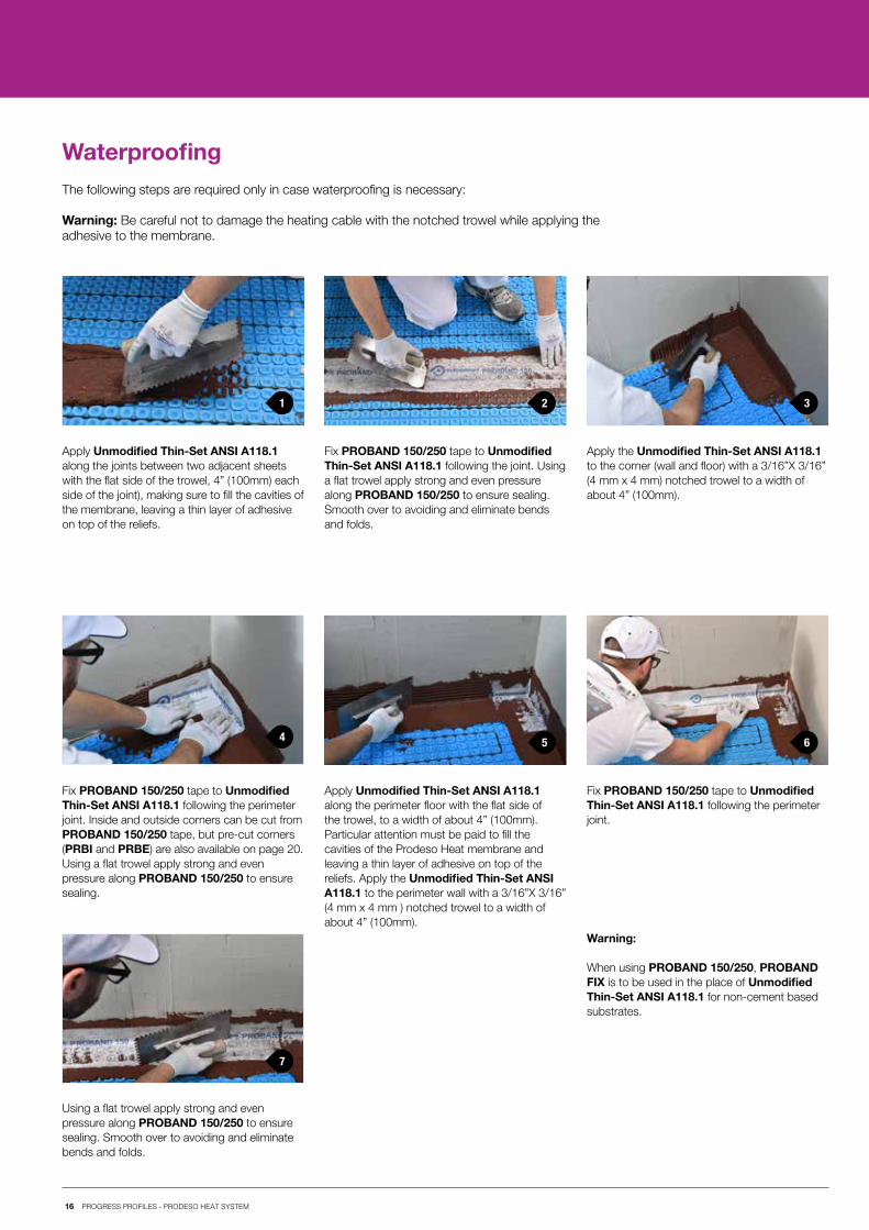
WaterproofingThe following steps are required only in case waterproofing is necessary:
Warning: Be careful not to damage the heating cable with the notched trowel while applying theadhesive to the membrane.
Apply Unmodified Thin-Set ANSI A118.1 along the joints between two adjacent sheets with the flat side of the trowel, 4” (100mm) each side of the joint), making sure to fill the cavities of the membrane, leaving a thin layer of adhesive on top of the reliefs.
Using a flat trowel apply strong and even pressure along PROBAND 150/250 to ensure sealing. Smooth over to avoiding and eliminate bends and folds.
Fix PROBAND 150/250 tape to Unmodified Thin-Set ANSI A118.1 following the perimeter joint.
Fix PROBAND 150/250 tape to Unmodified Thin-Set ANSI A118.1 following the perimeter joint. Inside and outside corners can be cut from PROBAND 150/250 tape, but pre-cut corners (PRBI and PRBE) are also available on page 20. Using a flat trowel apply strong and even pressure along PROBAND 150/250 to ensure sealing.
Fix PROBAND 150/250 tape to Unmodified Thin-Set ANSI A118.1 following the joint. Using a flat trowel apply strong and even pressure along PROBAND 150/250 to ensure sealing. Smooth over to avoiding and eliminate bends and folds.
Apply the Unmodified Thin-Set ANSI A118.1 to the corner (wall and floor) with a 3/16”X 3/16” (4 mm x 4 mm) notched trowel to a width of about 4” (100mm).
Apply Unmodified Thin-Set ANSI A118.1 along the perimeter floor with the flat side of the trowel, to a width of about 4” (100mm). Particular attention must be paid to fill the cavities of the Prodeso Heat membrane and leaving a thin layer of adhesive on top of the reliefs. Apply the Unmodified Thin-Set ANSI A118.1 to the perimeter wall with a 3/16”X 3/16” (4 mm x 4 mm ) notched trowel to a width of about 4” (100mm).
Warning:
When using PROBAND 150/250, PROBAND FIX is to be used in the place of Unmodified Thin-Set ANSI A118.1 for non-cement based substrates.
16 PROGRESS PROFILES - PRODESO HEAT SYSTEM
17 PROGRESS PROFILES - PRODESO HEAT SYSTEM
Products
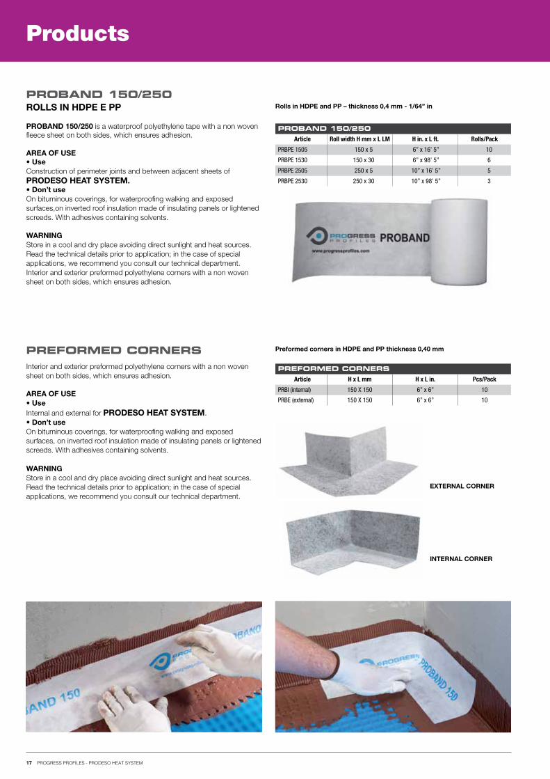
ROLLS IN HDPE E PP PROBAND 150/250
PREFORMED CORNERS
Rolls in HDPE and PP – thickness 0,4 mm - 1/64” in
PROBAND 150/250Article Roll width H mm x L LM H in. x L ft. Rolls/Pack
PRBPE 1505 150 x 5 6” x 16’ 5” 10
PRBPE 1530 150 x 30 6” x 98’ 5” 6
PRBPE 2505 250 x 5 10” x 16’ 5” 5
PRBPE 2530 250 x 30 10” x 98’ 5” 3
Preformed corners in HDPE and PP thickness 0,40 mm
PREFORMED CORNERSArticle H x L mm H x L in. Pcs/Pack
PRBI (internal) 150 X 150 6” x 6” 10
PRBE (external) 150 X 150 6” x 6” 10
INTERNAL CORNER
EXTERNAL CORNER
PROBAND 150/250 is a waterproof polyethylene tape with a non wovenfleece sheet on both sides, which ensures adhesion.
AREA OF USE• UseConstruction of perimeter joints and between adjacent sheets ofPRODESO HEAT SYSTEM.• Don’t useOn bituminous coverings, for waterproofing walking and exposedsurfaces,on inverted roof insulation made of insulating panels or lightenedscreeds. With adhesives containing solvents.
WARNINGStore in a cool and dry place avoiding direct sunlight and heat sources.Read the technical details prior to application; in the case of specialapplications, we recommend you consult our technical department.Interior and exterior preformed polyethylene corners with a non wovensheet on both sides, which ensures adhesion.
Interior and exterior preformed polyethylene corners with a non woven sheet on both sides, which ensures adhesion.
AREA OF USE• UseInternal and external for PRODESO HEAT SYSTEM.• Don’t useOn bituminous coverings, for waterproofing walking and exposedsurfaces, on inverted roof insulation made of insulating panels or lightenedscreeds. With adhesives containing solvents.
WARNINGStore in a cool and dry place avoiding direct sunlight and heat sources.Read the technical details prior to application; in the case of specialapplications, we recommend you consult our technical department.
1
4
2 3
18 PROGRESS PROFILES - PRODESO HEAT SYSTEM
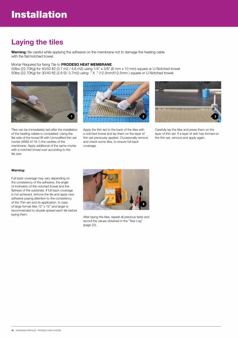
Installation
Laying the tilesWarning: Be careful while applying the adhesive on the membrane not to damage the heating cablewith the flat/notched trowel.
Tiles can be immediately laid after the installationof the heating cables is completed. Using theflat side of the trowel fill with Unmodified thin setmortar (ANSI A118.1) the cavities of themembrane. Apply additional of the same mortarwith a notched trowel over according to thetile size.
Apply the thin set to the back of the tiles witha notched trowel and lay them on the layer of thin set previously applied. Occasionally remove and check some tiles, to ensure full back coverage.
After laying the tiles, repeat all previous tests andrecord the values obtained in the “Test Log” (page 22).
Carefully lay the tiles and press them on the layer of thin set. If a layer of skin has formed on the thin set, remove and apply again.
Warning:
Full back coverage may vary depending on the consistency of the adhesive, the angle of inclination of the notched trowel and the flatness of the substrate. If full back coverage is not achieved, remove the tile and apply new adhesive paying attention to the consistency of the Thin set and its application. In case of large format tiles 12” x 12” and larger is recommended to double spread each tile before laying them.
Mortar Required for fixing Tile to PRODESO HEAT MEMBRANE.50lbs (22.70Kg) for 40/50 ft2 (3.7 m2 / 4.6 m2) using 1/4” x 3/8” (6 mm x 10 mm) square or U-Notched trowel50lbs (22.70Kg) for 30/40 ft2 (2.8 f2/ 3.7m2) using .” X .” (12.5mmX12.5mm ) square or U-Notched trowel.