module technology
TRANSCRIPT

8/6/2019 Module Technology
http://slidepdf.com/reader/full/module-technology 1/8
N E W C O N C E P T S I N S T E E L M A K I N G
Oxygen, carbon and uxes
innovative x injectiontechnology for ElectricArc Furnaces
The Module Technology

8/6/2019 Module Technology
http://slidepdf.com/reader/full/module-technology 2/8
o x y g
e n
slag reactions
SiO2
+ 2CaO = 2CaO.Sio2
SiO2
+ CaO = CaO.Sio2
P2O
5+ 4CaO = P
2O
5.4CaO
FeO + C = CO + Fe
2CO + O2
= 2CO2
C + CO2
= 2CO
reactions h steel
Si + O2
= SiO2
2Mn + O2
= 2MnO
2P + 5/2 O2
= P2O
5
Fe + ½ O2 = FeO
C + ½ O2 = CO
FeO + C = CO + Fe
C = [C]
s o f t
c a r b o n
d e e p
c a r b o n
l i m e
Technological conceptTheMODULETECHNOLOGY,state-of-the-artchemicalenergypackageforelectricarcfurnaces,combinesavarietyofxedinjectorsandrelatedcontroldevices(i.e.:valvesstands,carbon/uxesdispensers,automationsystemandHuman
MachineInterface)toaddchemicalenergy,forpost-combustion,forfoamingslagconditioningtoimproveEAFperformancesandtoreduceconversioncosts.TheMODULETECHNOLOGYcanbeappliedtoanytypeofelectricarcfurnace,(DC,AC,EBT,SPOUT),differentkindsofchargingmix(scrap,hotmetal,DRI,HBI,pigiron)andsteelgradeproduction(carbon,lowandalloyed,stainless).
Module technology benets• Reduceconversioncosts.
•Reduceelectricalenergy.
•Reducepowerontime.
•Reduceoperatorsworkload.
•Reduceoxygenandgaseousfuelconsumption duetoshut-offofoxygenandgaseous fuelshroudduringinjectionmode.
•Improveoveralloperatingefciency.
•Improvebathstirringandsteeltemperature/ chemistryhomogenization.
•Improvemaintenanceandoperationssafety.
•Improverefractorylife.
•Increasemetallicyield.
•Increaseproductivity.
•Increaseoxygenefciencyandcarbonrecovery.
•EAFoperateswithslagdoorclosed.
•Eliminatestheuseofoxygen/carbonlance
manipulatorsoperatingthroughtheslagdoor.
•Fullyautomaticchemicalenergypackagemanagement withuser-friendlyHumanMachineInterface.
•Reproducibleandconstantprocesscontrol.
•Easyandfastmaintenanceoperation.
MOCACARBON DISPENSER
AUTOMATIONSYSTEM
EAF INJECTORS
GASEUS FUEL
VALVES STANDOXYGEN
VALVES STANDMOLI
FLUXES DISPENSER
Equipment congurationThe equipment on board the EAF shell can be made-up of four different injectors. Each one has been developed to satisfy a very specic
requirement of the melting/rening process:
Denition Operating mode Feature
OXYGENJET SUPERSONIC OXYGEN INJECTION CHEMICAL ENERGY INPUT / DECARBURIZATION
CARBONJET ‘SOFT’ CARBON INJECTION FOAMING SLAG CONDITIONING
HI_JET ‘DEEP’ CARBON INJECTION CHEMICAL ENERGY INPUT
LIMEJET LIME/DOLO-LIME/FINES INJECTION FOAMING SLAG CONDITIONING
8/6/2019 Module Technology
http://slidepdf.com/reader/full/module-technology 3/8
Module Technology installationAwiderangeofsolutionshavebeendesignedanddevelopedtondinjectors’optimumpositioninsidetheEAFshell,avoidingdamagesfromscrapfallingandreachingacorrectgeometricalconguration.
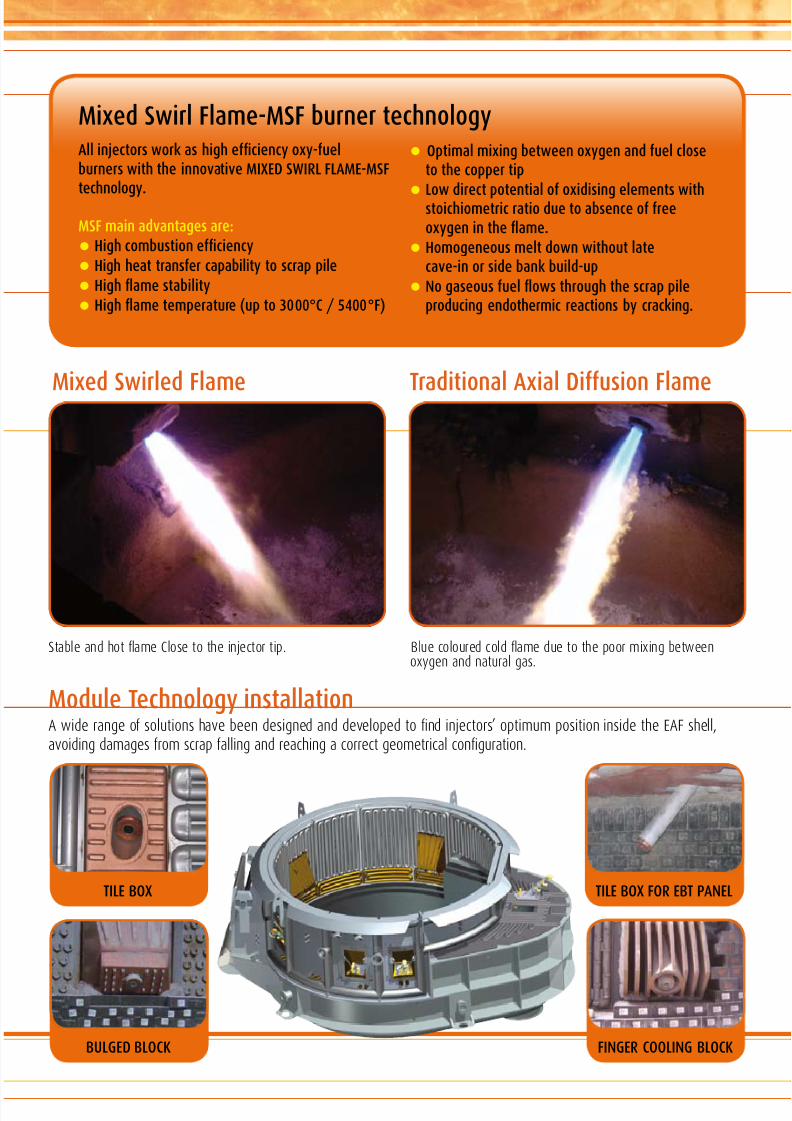
Mixed Swirl Flame-MSF burner technologyAll injectors wor as high efciency oxy-fuelburners with the innovative MIXED SWIRL FLAME-MSF
technology.
MSF main advantages are:
• High combustion efciency
• High heat transfer capability to scrap pile
• High ame stability
• High ame temperature (up to 3000°C / 5400°F)
TILE BOX
BULGED BLOCk
TILE BOX FOR EBT PANEL
FINGER COOLING BLOCk
StableandhotameClosetotheinjectortip. Bluecolouredcoldameduetothepoormixingbetweenoxygenandnaturalgas.
• Optimal mixing between oxygen and fuel closeto the copper tip
• Low direct potential of oxidising elements withstoichiometric ratio due to absence of freeoxygen in the ame.
• Homogeneous melt down without latecave-in or side ban build-up
• No gaseous fuel ows through the scrap pileproducing endothermic reactions by cracing.
Mixed Swirled Flame Traditional Axial Diffusion Flame

8/6/2019 Module Technology
http://slidepdf.com/reader/full/module-technology 4/8
OxygenjetFor oxygen lancing. This injector delivers a highlycoherent supersonic stream of oxygen that penetrates intothe steel bath for carbon oxidation and other oxidizingreactions in the steel / slag interface.
For deep injection of carbon nes at sonic speed into liquidsteel. This tool allows a high energy recovery associated tonal carbon control in the liquid steel.
Hi_Jet (Patented intellectual property # W003/091461 A1)
Injector Operating Mode Features
Hi_Jet
Burner – MSF-Mixed Swirled Flame technology.
Injection
– Sonic carbon injection (>400 m/sec).– Deep and high-efcient carbon injection in the liquid steel
to generate chemical energy.– Deep and high-efcient carbon injection in the liquid steel for metallurgical
process control (lower oxygen activity in the liquid steel before tapping).
– Recarburization mode.– Special nozzle design avoids the need of a shrouding ame.
Injector Operating Mode Features
Oxygenjet
Burner – MSF-Mixed Swirled Flame technology.
Injection– Supersonic-coherent injection of oxygen in the liquid steel.– Decarburization mode.– Special nozzle design avoids the need of a shrouding ame.

8/6/2019 Module Technology
http://slidepdf.com/reader/full/module-technology 5/8
CarbonjetFor carbon injection into the slag.The ‘soft’ carbon injection promotes FeO and MnO reductionwith consequent early slag foaming and better controlof metallic yield.
LimejetFor lime/dolo-lime/nes material (i.e.: dust, FeSi, FeCr, Al etc.)injection into the slag/steel interface for foaming slagconditioning.
Injector Operating Mode Features
LimeJet
Burner – MSF-Mixed Swirled Flame technology.
Injection
– Lime/Dolo-lime/Fines injection for foaming slag conditioning and V-ratiooptimization.
– In certain specic cases line/Dolo-lime nes can be shrouded
by oxygen/gaseous fuel to avoid nes built-up in front of the tip.
Injector Operating Mode Features
Carbonjet
Burner – MSF-Mixed Swirled Flame technology.
Injection– ‘Soft’ carbon injection for foaming slag conditioning and oxides reduction.– In certain specic cases carbon nes can be shrouded by oxygen/gaseous
fuel to avoid carbon built-up in front of the tip.

8/6/2019 Module Technology
http://slidepdf.com/reader/full/module-technology 6/8
Oxygen /gaseous fuelvalve standsDedicated valve stands are provided to measure, regulateand control the oxygen/gaseous fuel requirementsof injectors installed in the EAF shell.
Moli – uxes injection systemLime/dolo-lime/nes injection quantity requirements areprovided by an independent dispenser. Each ux injector musthave a dedicated individual ow control unit. The dispenserlocated under storage siloautomatically controlsthe nes ow accordingto a set-point imposedby recipes automaticallyloaded into the HMI.
• Dispenser encased in a self-standing steel frame.
• Independent pneumatic cabinet for transportair control.
• The electrical devices are connected up toa electrical box and Remote I/O unit xed on thedispenser steel frame.
• Continuous lime/dolo-lime/nes ow rate control.
• Optimal usage of transport air.
• Lime/dolo-lime/nes ow control is performedby 4-20mA slide-gate valve.
• Transport air ow measurement is performedby VORTEX meter.
• Transport air ow control is performed by4-20mA valve.
• Distance from dispenser to injectors up to 70 meters(230ft).
• Automatic anti-clogging woring system.
• Prior to delivery dispenser is fully connected andtested in the worshop to chec the woringsequences and functionality.
• Pressurized dispenser is manufactured and certiedto comply with: 97/23/CE-pressure equipmentdirective, ASME Boiler and Pressure Vessel Code Sect.VIII Div.1 or other requested standards.
Features
• Measure and ow control for each oxygen/gaseousfuel line.
• ’Plug and wor’ manufacturing concept to minimizethe installation and connection time.
• Oxygen/gaseous fuel independent sids allowthe installation into separate compounds to provideabsolute safety standards.
• Prior to delivery valve stands are fully connected andtested in the worshop to chec the woringsequences and functionality.
• Lines are purged with compressed air to eliminatecostly shroud ame during injection mode.
• Oxygen piping made by stainless steel.
• Gaseous fuel lines have a double shut off valve.
• Gaseous fuel individual lines are purged with nitrogen
for 5/10 sec. at each start/stop.This eliminates the possibility of compressed air andgaseous fuel to be in contact with each other.
• Valve stands are manufactured and certied to complywith: PED 97/23/CE-pressure equipment directive,ATEX Ex II 3G Zone 1, ATEX Ex II 3G Zone 2 or otherrequested standards.
Features

8/6/2019 Module Technology
http://slidepdf.com/reader/full/module-technology 7/8
• Automation based on a modern full-digitalProgrammable Logic Controller (PLC).
• Remote I/O connection to eld equipment.
• Intelligent and user friendly Human Machine Interface(HMI) based on PC unit, LCD screen and eyboard.
• Fast performance control loops.
• Automation system interconnected via high-speedLocal Area Networ or via Ethernet.
• Alarms, consumption data and process reports arestored in a dedicated database.
• Automatic wor prole of the oxygen/gas/carbonuxes injection requirements related automatically tooperational parameters (i.e. electrical energyconsumption-Wh, melting time, etc.)
• Level 2 supported communication for data interchange
and acquisition of oxygen/gas/carbon/uxes set-pointproles from dedicated pacages (i.e.: foaming slagcontrol, EAF dynamic control, off-gas analysis).
• EAF downtime data collection and multidimensionalintelligent process analysis data ( MoreIntelligence).
• Complete HD & SW connection and functional testbefore equipment delivery.
• In-house PLC/HMI software development byhighly silled and experienced engineers.
FeaturesAutomation systemThe automation system (Level 1)allows fully automated operationof the entire process requirementsfor the Module Technology.The melting process proles,
alarms/status visualisation, trends,reports and chemical energypackage process overview aremanaged via user-friendly HumanMachine Interface (HMI).
Moca – carbon injection systemCarbon injection ow and quantity requirements areprovided by an independent dispenser. Each carbon injectormust have a dedicated individual ow rate control unit.The dispenser located underthe storage silo controlsthe carbon owaccording to aset-point imposedby recipesautomatically loadedinto the HMI.
• Dispenser encased in a self-standing steel frame.
• Independent pneumatic cabinet for transportair control.
• The electrical devices are connected up toelectrical box and Remote I/O unit xed on thedispenser steel frame.
• Continuous carbon ow control.
• Accurate tolerance of set point.
• Fast carbon ow stabilization.
• Optimal usage of transport air
• Carbon nes ow control is performed by 4-20mAceramic valve.
• Transport air ow measurement is performedby VORTEX meter.
• Transport air ow control is performed by4-20mA valve.
• Distance from dispenser to injectors up to 70 meters (230ft).
• Automatic anti-clogging woring system.
• Prior to delivery dispenser is fully connected and testedin the worshop to chec the woringsequences and functionality.
• Pressurized dispenser is manufactured and certiedto comply with: 97/23/CE-pressure equipment directive,ASME Boiler and Pressure Vessel Code Sect. VIII Div.1.or other requested standards.
Features

8/6/2019 Module Technology
http://slidepdf.com/reader/full/module-technology 8/8
More s.r.l. 33013 Gemona del Friuli (UD) Italy - Tel. +39.0432.973511 - Fax +39.0432.970676 - E mail: [email protected]
www.more-oxy.com
WorshopEquipment manufacturing and assembly is carried out in the MOREworkshop where all phases are quality controlled and monitoredvery carefully to achieve top-class quality standards ISO 9001-2000,97/23/CE and ATEX EX II 3G Zone 1 and 2.
The workshop is equipped with modern facilities to guarantee thehighest standards by highly professional employees; in-housecomponents welding are carried out through advantaged techniquesand all welders are certied. The warehouse, manufacturing andassembly buildings cover over 3400 sqm and are equipped with:
•MIG-TIGweldingpositions
•Weldingrobots
•Mechanicalassembly andtestinglines
•Electricassembly andtestinglines
•Hydraulic/pneumatic/ gastestbench
•Sand-blastingmachine
•Surfacetreatmentmachines
•Spraypaintingtunnel
ServicesMORE’s highly skilled specialists perform supervision of installation,start-up and commissioning of supplied technologies. Their deepknowledge of mechanical, electrical, automation and steel makingproduction processes is the key to success.
We constantly pursue a “customer satisfaction” based on a “Win-Win”relationship. After successful start-up, the end user is supported bycontinuous technical assistance that deals with supply of spare parts,on-site visits that verify performance achievements and controlmaintenance levels.
Our qualied team, integrated bymanufacturing exibility, can providea tailor-made source for consumableparts. This results in a promptand punctual delivery of orderedcomponents for the benet ofcustomer’s activity.
MORE offer the service of experiencedsteel making and process specialiststhat can meet clients’ needs related to:
•Processevaluation&analysis
•Operationalimprovements andprocessoptimization
•Reductionofconversions costs
•Installationand commissioningassistance
•Productionassistance
•Onsitetraining
The companyMORE srl, founded in 1984 and based in Gemona del Friuli (Italy),is a world-leading supplier of a wide range of technologies relatedto chemical energy packages (oxygen, carbonaceous fuels,lime and others nes injection) and auxiliary equipment for electricarc furnace and steel-making industry.
MORE employs highly skil led professionals that ensure excellentquality equipment, reliability and safety. Mechanical, electricaland automation design activities are performed by internalspecialists with extensive experience in the steel making industry.The design department makes use of up-to-date software/toolssuch as CAD/CAE/CAM and Computational Fluids Dynamic (CFD)software to perform its tasks without compromise.
At MORE, technological research and development is intended as amission, to be accomplished by way of innovative equipment thatcan continuously improve overall EAF transformation costs.
M D - A 0 9 - M 0 4 - R 0 0