models: m1800; m4000; m2000; m2200; m2800 w1800; … · ge infrastructure sensing models: m1800;...
TRANSCRIPT
GE Infrastructure Sensing
Models: M1800; M4000; M2000; M2200; M2800 W1800; W2000; W2200
Hydraulic Deadweight Tester
imagination at work

HYDRAULIC DEADWEIGHT TESTER MODELS:
M1800, M4000, M2000, M2200, M2800, W1800,
W2000, W2200
GE INFRASTRUCTURE SENSING 10311 WESTPARK DRIVE, HOUSTON, TEXAS 77042
(713) 975-0547 FAX: (713) 975-6338
Release: PMAN-117-1D01 Revision: A Date: 02/1
-2-
WARRANTY
GE Infrastructure Sensing warrants its products to conform to or exceed the specifications as set forth in its catalogs in use at the time of sale and reserves the right, at its own discretion, without notice and without making similar changes in articles previously manufactured, to make changes in materials, designs, finish, or specifications. GE Infrastructure Sensing warrants products of its own factory against defects of material or workmanship for a period of one year from date of shipment.
Liability of GE Infrastructure Sensing under this warranty shall be limited to replacing, free of charge (FOB Houston, Texas), any such parts proving defective within the period of this warranty, but will not be responsible for transportation charges or consequential damages.
This warranty is not made for products manufactured by others which are illustrated and described in GE Infrastructure Sensing catalogs or incorporated in GE Infrastructure Sensing products in essentially the same form as supplied by the original manufacturer. However, GE Infrastructure Sensing agrees to use its best efforts to have original suppliers make good their warranties.
COPYRIGHT NOTICE
Copyright © 2004 by GE Infrastructure Sensing. All rights reserved. This document may not be reproduced in part or in whole without the express written consent of GE Infrastructure Sensing.
WARNING
PRESSURIZED VESSELS AND ASSOCIATED EQUIPMENT ARE POTENTIALLY DANGEROUS. THE APPARATUS DESCRIBED IN THIS MANUAL SHOULD BE OPERATED BY PERSONNEL TRAINED IN PROCEDURES THAT WILL ASSURE SAFETY TO THEMSELVES, TO OTHERS, AND TO THE EQUIPMENT.
-3-
DISCLAIMER
No representations or warranties are made with respect to the contents of this user’s manual. Further, GE Infrastructure Sensing reserves the right to revise this manual and to make changes from time to time in the content hereof without obligation to notify any person of such revision.
REVISION NOTICE
RELEASE NUMBER REVISION DATE OF
REVISION DESCRIPTION
PMAN-117-1D01 A 01/25/05 Original release.
-4-
TABLE OF CONTENTS WARRANTY .................................................................................................................................................................. -3- COPYRIGHT NOTICE................................................................................................................................................. -3- WARNING ..................................................................................................................................................................... -3- DISCLAIMER ................................................................................................................................................................. -4- REVISION NOTICE ..................................................................................................................................................... -4- TABLE OF CONTENTS .............................................................................................................................................. -5-
SECTION 1.0 GENERAL INFORMATION............................................................................................................. -6-
SECTION 2.0 PREPARATION .................................................................................................................................. -8- 2.1 CONNECTIONS .............................................................................................................................. -8-
SECTION 3.0 PRIMING ...........................................................................................................................................-10- 3.1 SYSTEM WITHOUT PRIMING PUMP.....................................................................................-10- 3.2 SYSTEMS WITH PRIMING PUMP ...........................................................................................-10-
SECTION 4.0 OPERATION .....................................................................................................................................-11- 4.1 STANDARD INSTRUMENTS (WITH & WITHOUT PRIMING PUMP .............................-11- 4.2 STANDARD INSTRUMENTS (WITH OPTIONAL PUMP MOTOR DRIVE) ....................-12-
SECTION 5.0 CALIBRATION IN DIFFERENT PRESSURE UNITS ...............................................................-14- 5.1 CONVERSION WEIGHTS...........................................................................................................-14- 5.2 SOFTWARE ....................................................................................................................................-14-
SECTION 6.0 MAINTENANCE AND SERVICING ............................................................................................-15- 6.1 PCU ASSEMBLY............................................................................................................................-15- 6.2 ASSEMBLY (2 & 3mm NOMINAL DIAMETERS).................................................................-18- 6.3 PCU ASSEMBLY (5mm NOMINAL DIAMETER)..................................................................-20- 6.4 ASSEMBLY - MOTOR DRIVE (10mm NOMINAL)..............................................................-24- 6.5 ASSEMBLY - MOTOR DRIVE (2 & 3mm NOMINAL DIAMETER) ..................................-25- 6.6 TOP PLATE REMOVAL................................................................................................................-25- 6.7 SCREW PRESS ASSEMBLY (SYSTEMS WITHOUT PRIMING PUMP)...........................-26- 6.8 SCREW PRESS ASSEMBLY (SYSTEMS WITH PRIMING PUMP)....................................-27- 6.9 PRIMING PUMP ASSEMLBY.....................................................................................................-30-
SECTION 7.0 FAULT FINDING .............................................................................................................................-33- 7.1 POOR PCU SPIN/SENSITIVITY ................................................................................................-33- 7.2 HIGH PCU FALL RATE................................................................................................................-33- 7.3 SYSTEM WILL NOT PRIME .......................................................................................................-34- 7.4 SYSTEM WILL NOT PRESSURIZE ...........................................................................................-34- 7.5 PRIMING PUMP MALFUNCTION............................................................................................-34- 7.6 CANNOT REACH MAXIMUM PRESSURE.............................................................................-35-
SECTION 8.0 STORAGE AND TRANSPORTATION ........................................................................................-36-
SECTION 9.0 ANCILLARY EQUIPMENT ............................................................................................................-37-
-5-
SECTION 1.0 GENERAL INFORMATION
Deadweight Testers are the primary standard for pressure measurement. utilizing the well-proven Piston-Gage system, consisting of a vertically mounted, precision lapped Piston and Cylinder assembly, accurately calibrated weight masses (Force) are loaded on the piston (Area), which rises freely within its cylinder. These weights balance the upward force created by the pressure within the system.
PRESSURE = FORCEAREA
Each weight is marked with the tester serial number, and the pressure measured when placed on a correctly spinning and floating piston. The total pressure measured is the summation of the weights plus the piston weight carrier assembly.
The deadweight tester has been calibrated to the Gravity, Temperature and Air Density stated on the certificate. Equations and factors are given on the certificate to adjust for any variations in these environmental conditions.
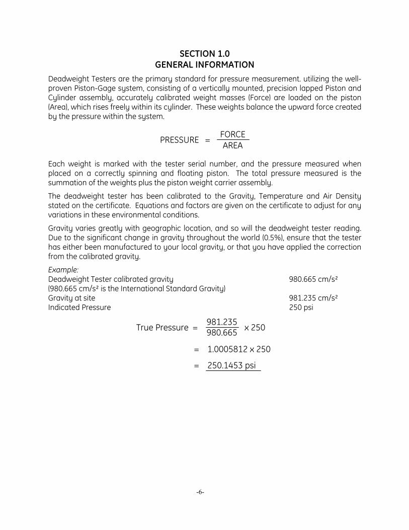
Gravity varies greatly with geographic location, and so will the deadweight tester reading. Due to the significant change in gravity throughout the world (0.5%), ensure that the tester has either been manufactured to your local gravity, or that you have applied the correction from the calibrated gravity.
Example: Deadweight Tester calibrated gravity 980.665 cm/s² (980.665 cm/s² is the International Standard Gravity) Gravity at site 981.235 cm/s² Indicated Pressure 250 psi
True Pressure = 981.235980.665 x 250
= 1.0005812 x 250
= 250.1453 psi
-6-
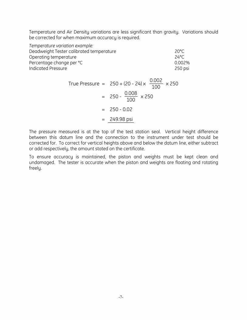
Temperature and Air Density variations are less significant than gravity. Variations should be corrected for when maximum accuracy is required.
Temperature variation example: Deadweight Tester calibrated temperature 20°C Operating temperature 24°C Percentage change per °C 0.002% Indicated Pressure 250 psi
True Pressure = 250 + (20 - 24) x x 2500.002100
= 250 - 0.008100 x 250
= 250 - 0.02
= 249.98 psi The pressure measured is at the top of the test station seal. Vertical height difference between this datum line and the connection to the instrument under test should be corrected for. To correct for vertical heights above and below the datum line, either subtract or add respectively, the amount stated on the certificate.
To ensure accuracy is maintained, the piston and weights must be kept clean and undamaged. The tester is accurate when the piston and weights are floating and rotating freely.
-7-
SECTION 2.0 PREPARATION
The deadweight tester must be setup on a level, stable workbench or similar surface. Remove capstan from instrument lid and refit to screw press. Level the tester using the four adjustable feet to the bubble level attached to the top plate. Remove reservoir bung and fill reservoir approximately ¾ full with the appropriate fluid. Fit the equipment under test (EUT) to the test station using the following method.
2.1 CONNECTIONS
IMPORTANT: Ensure that all devices are internally clean and free from contamination before connecting to the tester. Particle contamination can damage the sensitive piston assemblies, valve seats and screw press.
WARNING: DO NOT use Teflon/PTFE tape on these connections, as this will prevent correct sealing.
Before connection, ensure that there is a test seal fitted to the test station. Check that the sealing face of the device to be fitted is clean and undamaged, as scratches or dents can form leak-paths.
Note: The thread on the test station, and the lower part of the gage adaptors is LEFT-HANDED. The following procedure details the correct method for mounting devices using these adaptors: -
To calibrate panel-mounted gages with pressure connections in the rear, use a T3700 Angle Adaptor (see Ancillary Equipment).
-8-
-9-
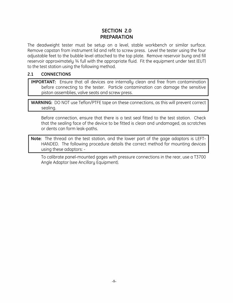
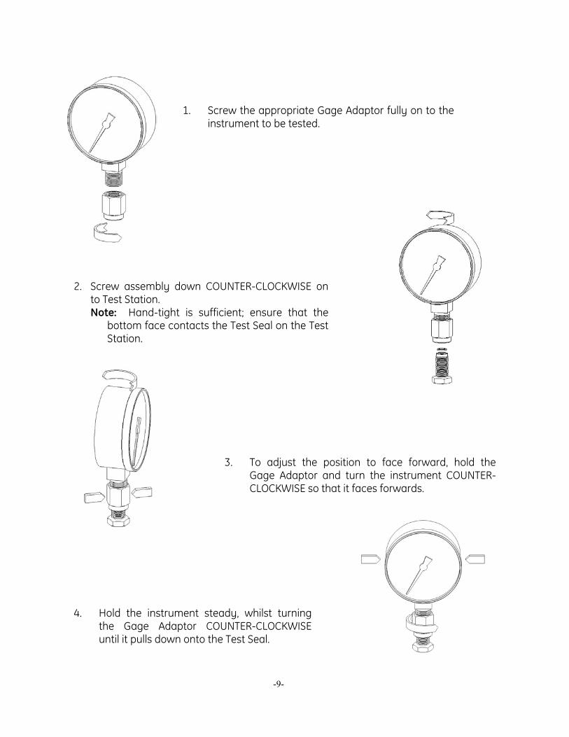
4. Hold the instrument steady, whilst turningthe Gage Adaptor COUNTER-CLOCKWISEuntil it pulls down onto the Test Seal.
2. Screw assembly down COUNTER-CLOCKWISE onto Test Station. Note: Hand-tight is sufficient; ensure that the
bottom face contacts the Test Seal on the TestStation.
3. To adjust the position to face forward, hold theGage Adaptor and turn the instrument COUNTER-CLOCKWISE so that it faces forwards.
1. Screw the appropriate Gage Adaptor fully on to theinstrument to be tested.
SECTION 3.0 PRIMING
3.1 SYSTEMS WITHOUT PRIMING PUMP
3.2.1 Open reservoir valve one turn counter-clockwise and turn capstan fully in.
3.2.2 Close valve [1] and turn capstan fully out.
3.2.3 Open valve and turn capstan fully in.
NOTE: During this operation, bubbles may appear in the reservoir, as trapped air is expelled. For large volumes, repeat steps 3.1.2 & 3 until no further bubbles appear.
3.2.4 With valve open, turn capstan fully out and close valve. The tester is now ready for use.
3.2 SYSTEMS WITH PRIMING PUMP
3.2.1 Open reservoir valve one turn counter-clockwise and turn capstan fully in.
3.2.2 Pump the priming pump two times.
3.2.3 Close valve [1] and turn capstan fully out.
3.2.4 Open valve and turn capstan fully in.
NOTE: During this operation, bubbles may appear in the reservoir, as trapped air is expelled. For large volumes, repeat steps 3 & 4 until no further bubbles appear.
3.2.5 With valve open, turn capstan fully out and close valve. The tester is now ready for use.
[1] WARNING: Turning the capstan out with the reservoir valve closed will generate approximately 15 inHg / 0.5 bar vacuum. If the EUT is vacuum sensitive, leave valve open during priming operation.
-10-
SECTION 4.0 OPERATION
4.1 STANDARD INSTRUMENTS (WITH AND WITHOUT PRIMING PUMP)
4.1.1 Select the required weights and stack them on the appropriate piston assembly. The pressure measured is the sum of the weights plus the piston/weight carrier.
DUAL PISTON MODELS: The pistons are matched in a ratio of effective areas (20:1 or 10:1) and the weights will be marked accordingly with both high and low pressure values. Turn the capstan in to generate pressure.
4.1.2 For models fitted with the optional priming pump, the initial pressure (up to approximately 100 psi / 7 bar) can be generated using this pump. Please note that this is intended to aid system priming only, and cannot be used to generate high pressures.
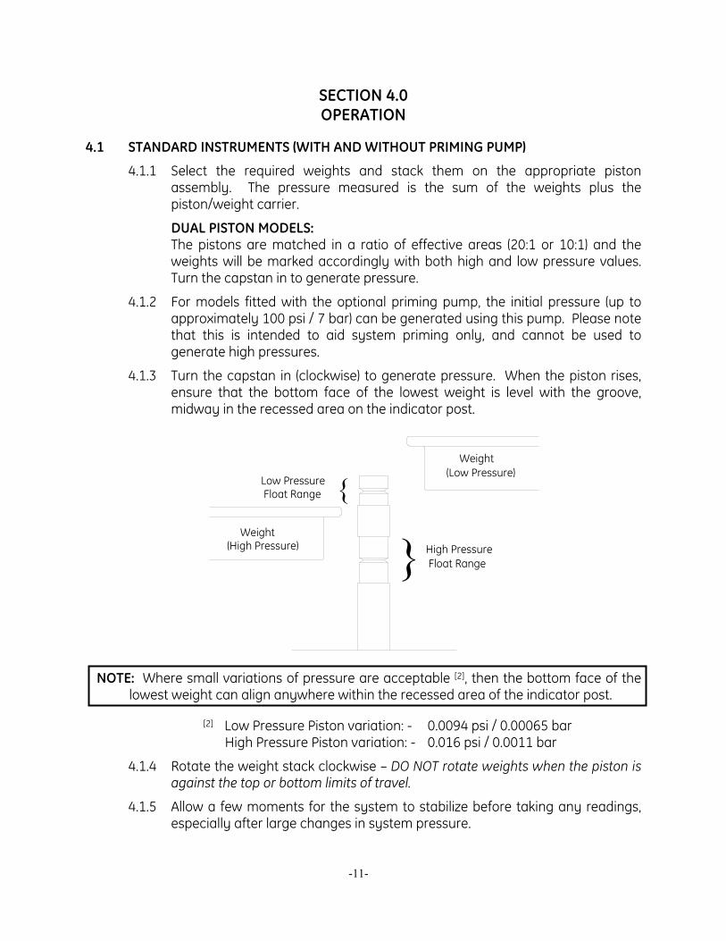
4.1.3 Turn the capstan in (clockwise) to generate pressure. When the piston rises, ensure that the bottom face of the lowest weight is level with the groove, midway in the recessed area on the indicator post.
}
}
High Pressure Float Range
Low Pressure Float Range
Weight(Low Pressure)
Weight(High Pressure)
NOTE: Where small variations of pressure are acceptable [2], then the bottom face of the lowest weight can align anywhere within the recessed area of the indicator post.
[2] Low Pressure Piston variation: - 0.0094 psi / 0.00065 bar High Pressure Piston variation: - 0.016 psi / 0.0011 bar
4.1.4 Rotate the weight stack clockwise – DO NOT rotate weights when the piston is against the top or bottom limits of travel.
4.1.5 Allow a few moments for the system to stabilize before taking any readings, especially after large changes in system pressure.
-11-
NOTE: Large, sudden changes in pressure will cause the system temperature to rise or fall, which can cause instrument readings to change as the fluid in the system expands or contracts, thus increasing or decreasing the pressure. This is often interpreted as a leak.
4.1.6 For the next, higher calibration point, repeat from step 4.1 above.
4.1.7 To measure reducing pressures, remove the necessary weights, and turn the capstan out so that the weight stack floats at the correct height, then rotate clockwise.
4.1.8 Depressurize the system by turning the capstan FULLY OUT – Never release the system pressure without turning the capstan fully out, as sudden depressurization will cause the weight stack to fall quickly which may damage the piston assembly.
4.1.9 Remove weight stack.
4.2 STANDARD INSTRUMENTS (WITH OPTIONAL MOTOR DRIVE)
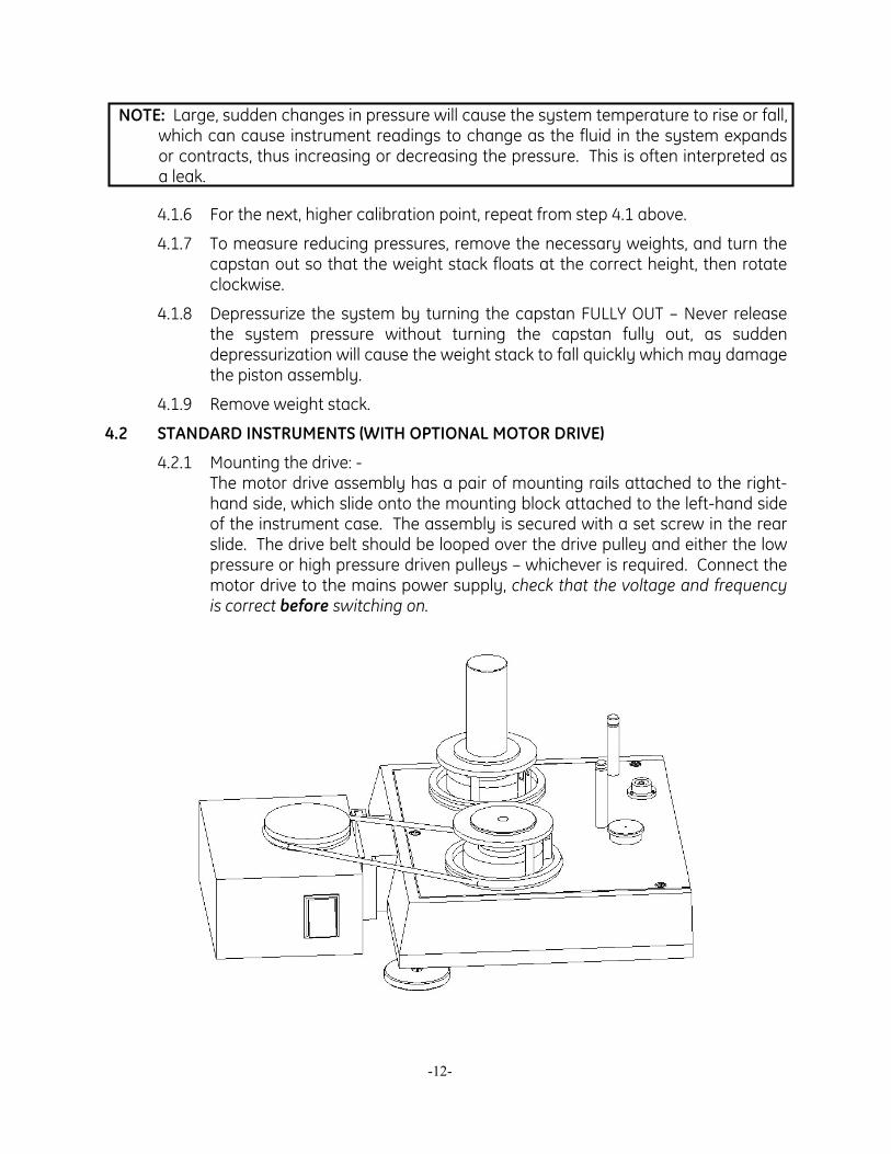
4.2.1 Mounting the drive: - The motor drive assembly has a pair of mounting rails attached to the right-hand side, which slide onto the mounting block attached to the left-hand side of the instrument case. The assembly is secured with a set screw in the rear slide. The drive belt should be looped over the drive pulley and either the low pressure or high pressure driven pulleys – whichever is required. Connect the motor drive to the mains power supply, check that the voltage and frequency is correct before switching on.
-12-
4.2.2 Select the weights and pressurize the system as described in sections 4.1.1 & 4.1.2 above.
NOTE: As the motor-driven weight carrier design differs in height from the standard version, the single float height indicator post is replaced by two individual indicator posts.
4.2.3 Once the weight stack is at the correct float height, rotate the weights by switching on the motor drive. DO NOT operate the motor drive when the piston is against the top or bottom limits of travel.
4.2.4 Allow a few moments for the system to stabilize before taking any readings, especially after large changes in system pressure.
NOTE: Large, sudden changes in pressure will cause the system temperature to rise or fall, which can cause instrument readings to change as the fluid in the system expands or contracts, thus increasing or decreasing the pressure. This is often interpreted as a leak.
4.2.5 To stop the weight rotation, switch off the motor drive and allow the weights to come to rest before attempting to change them.
4.2.6 To calibrate higher and lower pressure points, follow the instructions in section 4.1.5 above.
-13-
SECTION 5.0 CALIBRATION IN DIFFERENT PRESSURE UNITS
The deadweight tester can be used to calibrate in different pressure units in either of two methods: -
5.1 CONVERSION WEIGHTS A set of Conversion Weights can be supplied, marked in the required pressure unit,
and adjusted to the correct mass for use with the existing piston(s).
The set includes (where applicable) a replacement low-pressure weight carrier table, and a replacement high-pressure weight carrier ring. These items are simply exchanged for the original items when using the conversion weights. Calibration is carried out as described above, with logical pressure increments throughout the operating range, avoiding the need to perform pressure unit conversion calculations.
5.2 SOFTWARE PressCal software is available for use with deadweight testers, and will allow users to
apply all necessary corrections (e.g. local gravity, temperature, pressure head, etc.) to enhance the pressure measurement accuracy of the instrument.
It will allow calibration in any of 12 different pressure units, using the existing weight set.
-14-
SECTION 6.0 MAINTENANCE AND SERVICING
IMPORTANT: The piston / cylinder assembly is the most critical and sensitive part of the deadweight tester. To maintain accuracy, the piston must always slide freely in the cylinder, and the hydraulic fluid must remain clean.
6.1 PCU Assembly (10 mm Nominal Diameter) PISTON DISASSEMBLY:
6.1.1 Using a small pinhead hammer and a suitable flat-ended punch, tap lightly on the end of the piston (B), through the center of the weight carrier (F). Remove weight carrier.
6.1.2 Unscrew the cylinder (E or I); use the dowel hole if the cylinder is tight.
6.1.3 Carefully withdraw the piston from the cylinder.
6.1.4 If required, lift support ring (C) from around o-ring (D or H), the o-ring can now be withdrawn from the piston.
PISTON CLEANING: 6.1.5 Use “non-fluffing”, non-abrasive, lint-free tissue or absorbent cloth. Hold the
piston by the larger “head” end, and rub the tissue back and forth along its length.
6.1.6 To remove all traces of contamination (especially important with Water Operated Testers), the piston can be cleaned in a suitable solvent.
NOTE: O-ring seals (where fitted) are nitrile rubber, and should not be immersed in solvents, as they will become damaged. They should be wiped carefully with a new tissue
6.1.7 After removal from the solvent, using a NEW tissue, repeat the cleaning procedure in 6.1.5.
6.1.8 Place piston carefully on a NEW tissue where it will not be damaged while the cylinder is cleaned.
IMPORTANT: NEVER TOUCH THE WORKING SURFACE OF A CLEAN PISTON WITH BARE FINGERS – THE NATURAL OIL IN YOUR SKIN CAN CAUSE THE PISTON AND CYLINDER TO STICK.
6.1.9 Wipe excess fluid from the outside surfaces of the cylinder (E or I).
6.1.10 Roll a NEW tissue into a tapered rod of appropriate size. Force the tissue through the cylinder bore whilst rotating. Ensure that the tissue is a tight fit inside the bore so that dirt and contamination is removed.
6.1.11 Repeat 6.1.10, using a NEW tissue, but from the opposite end of the cylinder.
6.1.12 Immerse the cylinder in a suitable, clean solvent, see note in 6.1.6 above.
-15-
6.1.13 After removal from the solvent, using a NEW tissue, repeat the cleaning procedure in 6.1.10 & 11.
PISTON RE-ASSEMBLY: 6.1.14 Replace the clean support ring (C) over the tapered end of the piston, followed
by the o-ring (D or H). Slide the o-ring to the bottom of the piston so that it holds the support ring in place.
6.1.15 Holding the piston by the larger “head” end, dip the other end into a container of clean operating fluid, and transfer to the bore in the underside (threaded end) of the cylinder. Allow the fluid to run through the bore. Repeat this 2 or 3 times to ensure a good film of clean operating fluid exists in the cylinder bore.
6.1.16 Carefully introduce the piston into the underside of the cylinder, and push gently through (the piston will normally slide freely through due to its own weight).
NEVER FORCE THE PISTON INTO ITS CYLINDER OR DAMAGE WILL RESULT. If resistance is felt, introduce more fluid. If resistance continues, re-clean piston, cylinder or both. If, after repeated cleaning, the piston still will not slide freely within the cylinder, then permanent damage may have occurred. In which case, the parts should be returned to the factory for evaluation or replacement.
6.1.17 Stand assembly upright on a clean, hard, stable surface. Ensure that the o-ring (D or F) and support ring (C) are both located centrally around the piston. Push the cylinder down so that the o-ring is forced evenly inside the support ring.
6.1.18 Ensure that the weight carrier (F) is clean (especially the central mounting hole), and place on the tapered end of the piston. Tap lightly using the palm of the hand to locate on the taper.
6.1.19 Carefully screw the assembly into the instrument, ensuring that the seal (A or G) is clean and undamaged, and correctly re-fitted.
REPLACEMENT PCU ASSEMBLY
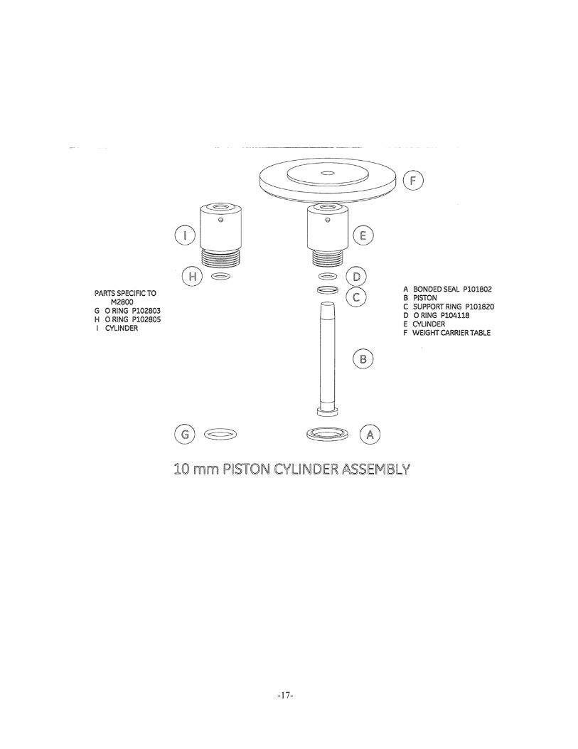
NOTE: The piston and cylinder are a matched pair, which is calibrated and adjusted to a calculated mass figure. If, for any reason, the piston or cylinder becomes damaged, then the entire assembly must be replaced. The replacement assembly consists of the following components: -
B through F (Standard Instruments). B, C, H, I & F (M2800 Instruments).
-16-
-17-
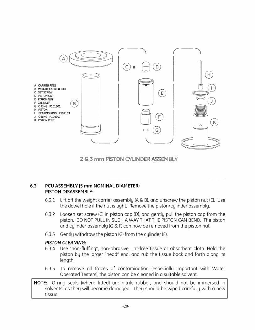
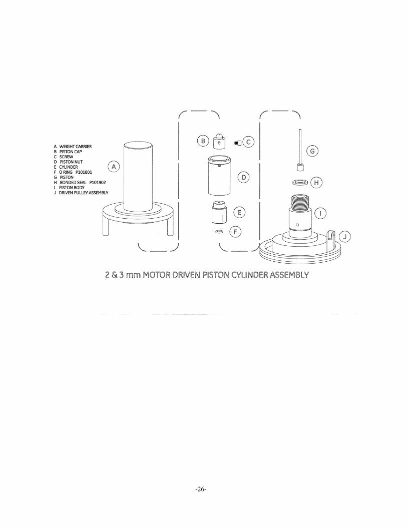
6.2 ASSEMBLY (2 & 3 mm NOMINAL DIAMETERS) PISTON DISASSEMBLY:
6.2.1 Lift off the weight carrier assembly (A & B), and unscrew the piston nut (E). Use the dowel hole if the nut is tight. Remove the piston/cylinder assembly.
6.2.2 Loosen set screw (C) in piston cap (D), and gently pull the piston cap from the piston. DO NOT PULL IN SUCH A WAY THAT THE PISTON CAN BEND. The piston and cylinder assembly (H & F) can now be removed from the piston nut.
6.2.3 Gently withdraw the piston (H) from the cylinder (F).
PISTON CLEANING: 6.2.4 Use “non-fluffing”, non-abrasive, lint-free tissue or absorbent cloth. Hold the
piston by the larger “head” end, and rub the tissue back and forth along its length.
6.2.5 To remove all traces of contamination (especially important with Water Operated Testers), the piston can be cleaned in a suitable solvent.
NOTE: O-ring seals (where fitted) are nitrile rubber, and should not be immersed in solvents, as they will become damaged. They should be wiped carefully with a new tissue.
6.2.6 After removal from the solvent, using a NEW tissue, repeat the cleaning procedure in 6.2.5.
6.2.7 Place piston carefully on a NEW tissue where it will not be damaged while the cylinder is cleaned.
IMPORTANT: NEVER TOUCH THE WORKING SURFACE OF A CLEAN PISTON WITH BARE FINGERS – THE NATURAL OIL IN YOUR SKIN CAN CAUSE THE PISTON AND CYLINDER TO STICK.
6.2.8 Wipe excess fluid from the outside surfaces of the cylinder (F).
6.2.9 Roll a NEW tissue into a tapered rod of appropriate size. Force the tissue through the cylinder bore whilst rotating. Ensure that the tissue is a tight fit inside the bore so that dirt and contamination is removed.
6.2.10 Repeat 6.2.9, using a NEW tissue, but from the opposite end of the cylinder.
6.2.11 Immerse the cylinder in a suitable, clean solvent, see note in 6.2.5 above.
6.2.12 After removal from the solvent, using a NEW tissue, repeat the cleaning procedure in 6.2.9 & 10.
PISTON RE-ASSEMBLY: 6.2.13 Replace o-ring (G) in the counter-bore in the underside of the cylinder (F),
ensuring that it is located correctly and evenly.
6.2.14 Holding the piston by the larger “head” end, dip the other end into a container of clean operating fluid, and transfer to the bore in the underside of the
-18-
cylinder. Allow the fluid to run through the bore. Repeat this 2 or 3 times to ensure a good film of clean operating fluid exists in the cylinder bore.
6.2.15 Carefully introduce the piston into the underside of the cylinder, and push gently through.
6.2.16 NEVER FORCE THE PISTON INTO ITS CYLINDER OR DAMAGE WILL RESULT. If resistance is felt, introduce more fluid. If resistance continues, re-clean piston, cylinder or both. If, after repeated cleaning, the piston still will not slide freely within the cylinder, then permanent damage may have occurred. In which case, the parts should be returned to the factory for evaluation or replacement.
6.2.17 Insert piston/cylinder assembly into piston nut (E) through the threaded end, such that the shoulder on the cylinder is located within the central bore of the nut.
6.2.18 Replace piston cap (D), and secure with set screw (C) – DO NOT OVERTIGHTEN.
6.2.19 Carefully screw the assembly into the instrument, ensuring that the o-ring (J) is clean and undamaged, and correctly fitted to the piston post (K).
6.2.20 Replace weight carrier assembly (A & B), ensuring that it locates correctly on the piston cap.
REPLACEMENT PCU ASSEMBLY
NOTE: The piston and cylinder are a matched pair, which is calibrated and adjusted to a calculated mass figure. If, for any reason, the piston or cylinder becomes damaged, then the entire assembly must be replaced. The replacement assembly consists of the following components: -A through H.
-19-
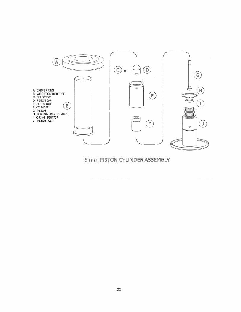
6.3 PCU ASSEMBLY (5 mm NOMINAL DIAMETER)
PISTON DISASSEMBLY:
6.3.1 Lift off the weight carrier assembly (A & B), and unscrew the piston nut (E). Use the dowel hole if the nut is tight. Remove the piston/cylinder assembly.
6.3.2 Loosen set screw (C) in piston cap (D), and gently pull the piston cap from the piston. DO NOT PULL IN SUCH A WAY THAT THE PISTON CAN BEND. The piston and cylinder assembly (G & F) can now be removed from the piston nut.
6.3.3 Gently withdraw the piston (G) from the cylinder (F).
PISTON CLEANING: 6.3.4 Use “non-fluffing”, non-abrasive, lint-free tissue or absorbent cloth. Hold the
piston by the larger “head” end, and rub the tissue back and forth along its length.
6.3.5 To remove all traces of contamination (especially important with Water Operated Testers), the piston can be cleaned in a suitable solvent.
NOTE: O-ring seals (where fitted) are nitrile rubber, and should not be immersed in solvents, as they will become damaged. They should be wiped carefully with a new tissue.
-20-
6.3.6 After removal from the solvent, using a NEW tissue, repeat the cleaning procedure in 6.3.5.
6.3.7 Place piston carefully on a NEW tissue where it will not be damaged while the cylinder is cleaned.
IMPORTANT: NEVER TOUCH THE WORKING SURFACE OF A CLEAN PISTON WITH BARE FINGERS – THE NATURAL OIL IN YOUR SKIN CAN CAUSE THE PISTON AND CYLINDER TO STICK.
6.3.8 Wipe excess fluid from the outside surfaces of the cylinder (F).
6.3.9 Roll a NEW tissue into a tapered rod of appropriate size. Force the tissue through the cylinder bore whilst rotating. Ensure that the tissue is a tight fit inside the bore so that dirt and contamination is removed.
6.3.10 Repeat 6.3.9, using a NEW tissue, but from the opposite end of the cylinder.
6.3.11 Immerse the cylinder in a suitable, clean solvent, see note in 6.3.5 above.
6.3.12 After removal from the solvent, using a NEW tissue, repeat the cleaning procedure in 6.3.9 & 10.
PISTON RE-ASSEMBLY: 6.3.13 Holding the piston by the larger “head” end, dip the other end into a container
of clean operating fluid, and transfer to the bore in the underside of the cylinder. Allow the fluid to run through the bore. Repeat this 2 or 3 times to ensure a good film of clean operating fluid exists in the cylinder bore.
6.3.14 Carefully introduce the piston into the underside of the cylinder, and push gently through.
6.3.15 NEVER FORCE THE PISTON INTO ITS CYLINDER OR DAMAGE WILL RESULT. If resistance is felt, introduce more fluid. If resistance continues, re-clean piston, cylinder or both. If, after repeated cleaning, the piston still will not slide freely within the cylinder, then permanent damage may have occurred. In which case, the parts should be returned to the factory for evaluation or replacement.
-21-
-22-
-23-
6.3.16 Insert piston/cylinder assembly into piston nut (E) through the threaded end, such that the shoulder on the cylinder is located within the central bore of the nut.
6.3.17 Replace piston cap (D), and secure with set screw (C) – DO NOT OVERTIGHTEN.
6.3.18 Carefully screw the assembly into the instrument, ensuring that the o-ring (I) is clean and undamaged, and correctly fitted to the piston post (J).
6.3.19 Replace weight carrier assembly (A & B), ensuring that it locates correctly on the piston cap.
REPLACEMENT PCU ASSEMBLY
NOTE: The piston and cylinder are a matched pair, which is calibrated and adjusted to a calculated mass figure. If, for any reason, the piston or cylinder becomes damaged, then the entire assembly must be replaced. The replacement assembly consists of the following components: - A through G.
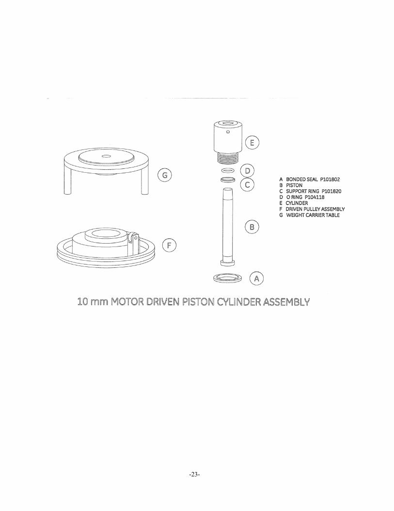
6.4 ASSEMBLY - MOTOR DRIVEN (10 mm NOMINAL DIAMETER) PISTON DISASSEMBLY:
6.4.1 Using a small pinhead hammer and a suitable flat-ended punch, tap lightly on the end of the piston (B), through the center of the weight carrier (G). Remove weight carrier
6.4.2 Loosen set screw in upper collar of the driven pulley assembly (F), and lift off, together with spacer washers below.
6.4.3 The remainder of the disassembly and cleaning procedure is identical to the standard 10 mm PCU, as far as 6.1.16, detailed above.
6.4.4 Once the piston is within the cylinder, and the o-ring and back-up correctly located, carefully screw the assembly into the instrument, ensuring that seal (A) is clean and undamaged, and correctly re-fitted.
6.4.5 Replace the driven pulley assembly and spacer washers over piston/cylinder assembly, and secure with set screw – Do not over-tighten.
6.4.6 Ensure that the weight carrier (G) is clean (especially the central mounting hole), and place on the tapered end of the piston.
REPLACEMENT PCU ASSEMBLY
NOTE: The piston and cylinder are a matched pair, which is calibrated and adjusted to a calculated mass figure. If, for any reason, the piston or cylinder becomes damaged, then the entire assembly must be replaced. The replacement assembly consists of the following components: - B through E and G.
6.5 ASSEMBLY - MOTOR DRIVEN (2 & 3 mm NOMINAL DIAMETER) PISTON DISASSEMBLY:
6.5.1 Lift off weight carrier (A), and unscrew the piston nut (D). Use the dowel hole if the nut is tight. Remove the piston/cylinder assembly.
-24-
6.5.2 The remainder of the disassembly and cleaning procedure is identical to the standard 2 & 3 mm PCU, as detailed in section 6.2 above.
REPLACEMENT PCU ASSEMBLY
NOTE: The piston and cylinder are a matched pair, which is calibrated and adjusted to a calculated mass figure. If, for any reason, the piston or cylinder becomes damaged, then the entire assembly must be replaced. The replacement assembly consists of the following components: -A through G.
6.6 TOP PLATE REMOVAL
NOTE: In order to perform maintenance procedures on the hydraulic system, the Top Plate Assembly must first be removed from the instrument case.
6.6.1 Depressurize the system, open the reservoir valve, and turn the capstan fully in.
6.6.2 Disconnect any EUT from the test station, and remove the fluid from the reservoir.
6.6.3 Remove the capstan from the inner hub of the screw press.
6.6.4 Remove the 4 screws from the instrument top plate, (1 at the mid-point of each edge).
6.6.5 Hold the top plate assembly by the test station and reservoir valve, and tilt the plate so that the rear edge is lifted, but the front edge remains in contact with the instrument case.
6.6.6 Slide the top plate towards the rear until the inner hub of the screw press is clear of the front lip of the instrument case.
6.6.7 Lift out the top plate assembly.
IMPORTANT: When handling the top plate assembly, it is good practice to remove the piston assemblies to avoid accidental damage.
NOTE: Replacement is simply the reverse of the above procedure.
-25-
-26-
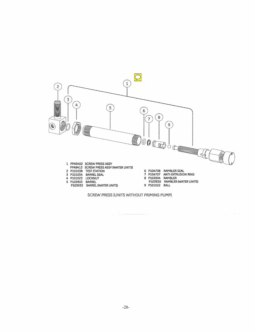
6.7 SCREW PRESS ASSEMBLY (SYSTEMS WITHOUT PRIMING PUMP)
6.7.1 Unscrew the large union nut (just behind the inner hub) of the screw press assembly.
6.7.2 Withdraw the lead screw assembly from the barrel (5), taking care not to drop the rambler assembly (8).
6.7.3 The white, anti-extrusion ring (7) is a PTFE spiral, and can be removed by “unwinding” it from the rambler.
6.7.4 When removing the rambler seal (6), take care not to use any tool that may have a sharp edge that will scratch the surfaces of the rambler, otherwise it may leak when reassembled.
6.7.5 The replacement rambler seal can be eased over the front of the rambler, and into the groove.
6.7.6 Similarly, the new anti-extrusion ring can be “wound” into the groove in the rambler, behind the rambler seal.
6.7.7 If it is necessary to remove the barrel (5), the locknut (4) must be loosened approximately ½ turn. The barrel can then be unscrewed from the test station (2).
NOTE: It is often easier to remove the barrel support bracket to allow greater movement, (remove the 2 screws from the upper side of the top plate).
6.7.8 Before re-fitting the barrel, ensure that the barrel seal (3) is correctly located in the counter-bore in the front of the barrel. Screw the barrel fully in to the test station, and secure with the locknut.
6.7.9 Re-align the barrel support bracket (if removed), and secure through the top plate with the 2 screws.
6.7.10 Ensure that the rambler assembly is correctly located on the end of the lead screw assembly. Carefully introduce the rambler into the open end of the barrel; making sure that it does not tilt when entering the barrel.
6.7.11 Push the lead screw assembly fully in to the barrel, ensuring that the key in the nut locates correctly in the slot in the barrel.
6.7.12 Re-tighten the barrel union nut.
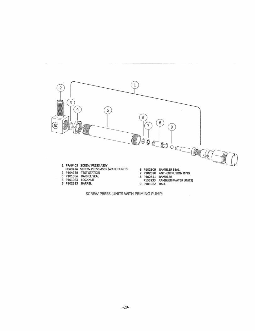
6.8 SCREW PRESS ASSEMBLY (SYSTEMS WITH PRIMING PUMP) The procedure for seal replacement is identical to that described in 6.7 above, however, units with fitted priming pumps have a screw press with a smaller bore and stroke length than standard.
The following diagram details the relevant parts.
NOTE: If the lead screw assembly shows signs of excessive wear, then it is very likely that the associated components have worn also, therefore the screw press assembly is available as a spare part – see diagrams for part numbers.
-27-
-28-
-29-
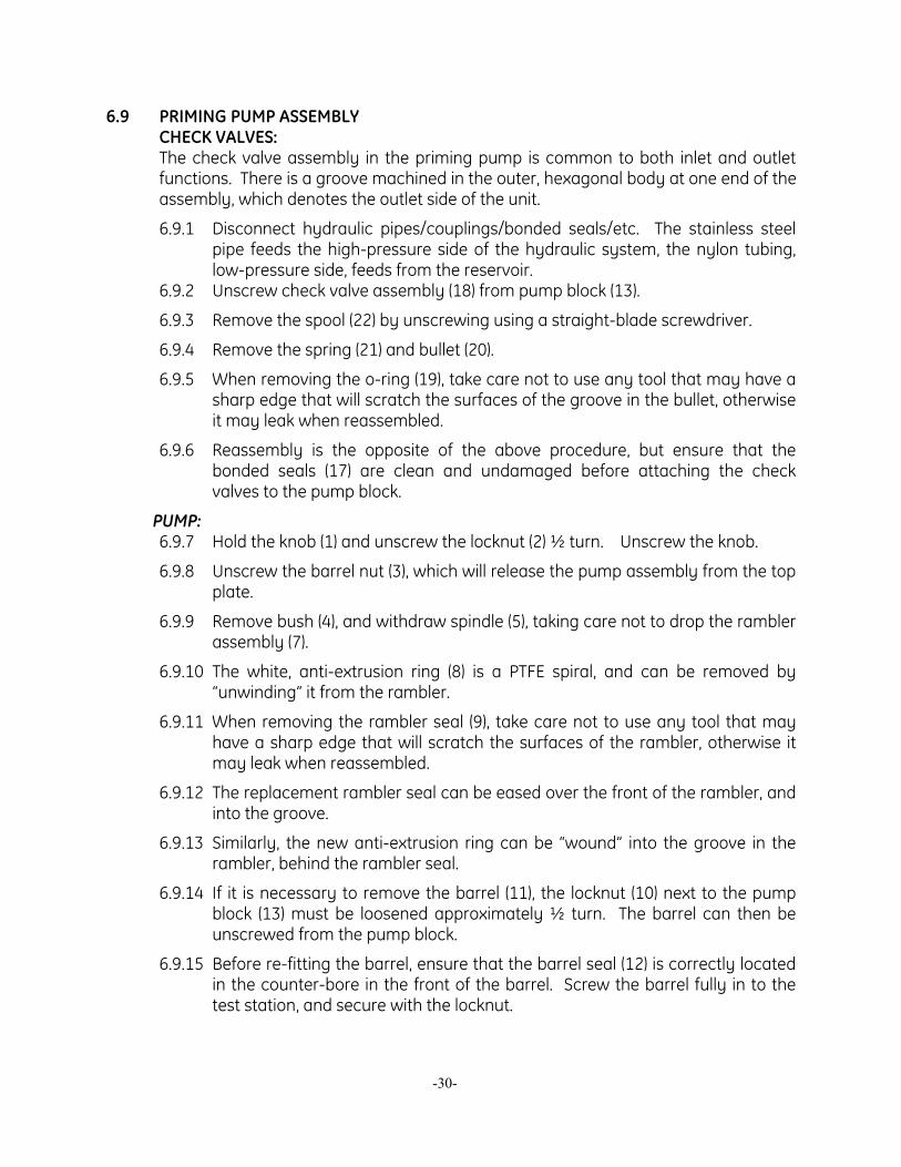
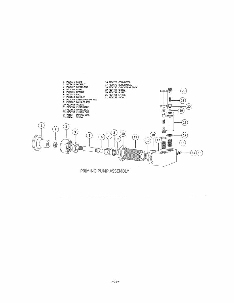
6.9 PRIMING PUMP ASSEMBLY CHECK VALVES: The check valve assembly in the priming pump is common to both inlet and outlet
functions. There is a groove machined in the outer, hexagonal body at one end of the assembly, which denotes the outlet side of the unit.
6.9.1 Disconnect hydraulic pipes/couplings/bonded seals/etc. The stainless steel pipe feeds the high-pressure side of the hydraulic system, the nylon tubing, low-pressure side, feeds from the reservoir.
6.9.2 Unscrew check valve assembly (18) from pump block (13).
6.9.3 Remove the spool (22) by unscrewing using a straight-blade screwdriver.
6.9.4 Remove the spring (21) and bullet (20).
6.9.5 When removing the o-ring (19), take care not to use any tool that may have a sharp edge that will scratch the surfaces of the groove in the bullet, otherwise it may leak when reassembled.
6.9.6 Reassembly is the opposite of the above procedure, but ensure that the bonded seals (17) are clean and undamaged before attaching the check valves to the pump block.
PUMP: 6.9.7 Hold the knob (1) and unscrew the locknut (2) ½ turn. Unscrew the knob.
6.9.8 Unscrew the barrel nut (3), which will release the pump assembly from the top plate.
6.9.9 Remove bush (4), and withdraw spindle (5), taking care not to drop the rambler assembly (7).
6.9.10 The white, anti-extrusion ring (8) is a PTFE spiral, and can be removed by “unwinding” it from the rambler.
6.9.11 When removing the rambler seal (9), take care not to use any tool that may have a sharp edge that will scratch the surfaces of the rambler, otherwise it may leak when reassembled.
6.9.12 The replacement rambler seal can be eased over the front of the rambler, and into the groove.
6.9.13 Similarly, the new anti-extrusion ring can be “wound” into the groove in the rambler, behind the rambler seal.
6.9.14 If it is necessary to remove the barrel (11), the locknut (10) next to the pump block (13) must be loosened approximately ½ turn. The barrel can then be unscrewed from the pump block.
6.9.15 Before re-fitting the barrel, ensure that the barrel seal (12) is correctly located in the counter-bore in the front of the barrel. Screw the barrel fully in to the test station, and secure with the locknut.
-30-
6.9.16 Ensure that the rambler assembly is correctly located on the end of the spindle (5). Carefully introduce the rambler into the open end of the barrel; making sure that it does not tilt when entering the barrel.
6.9.17 Replace the bush (4), ensuring that the smaller shoulder locates correctly in the barrel.
6.9.18 Pass the pump assembly through the hole in the top plate from below, and secure with the barrel nut (3).
NOTE: For correct pump operation, the barrel nut must hold the bush firmly in the end of the barrel. The upper locknut (10) may have been moved during disassembly, so to ensure correct re-assembly, unscrew the upper locknut 2 turns before assembling the pump in the top plate. Once the barrel nut is tight, the upper locknut can be re-tightened against the underside of the top plate, securing the pump assembly.
6.9.19 Replace locknut (2) and knob (1), secure with locknut.
6.9.20 Re-connect the hydraulic pipes/couplings/bonded seals/etc.
-31-
-32-
SECTION 7.0 FAULT FINDING
7.1 POOR PCU SPIN/SENSITIVITY GENERAL: The weights floating on a clean PCU assembly will rotate freely, slowing down gradually to a complete stop. If the rotation stops quickly, then the PCU may be dirty and require cleaning. DO NOT ROTATE THE PISTON IF IT IS DIRTY AS PERMENANT DAMAGE CAN OCCUR. If the spin/sensitivity of a recently cleaned PCU deteriorates quickly, then it is likely that the hydraulic system has become contaminated. During the normal operation of a deadweight tester, the working fluid flows slowly through the tiny gap between the piston and its cylinder. If the hydraulic system has become contaminated, any particles will tend to move towards the PCU(s) and thus affect their performance, and possibly damage them. If this is the case, the system must be completely dismantled, thoroughly cleaned and rebuilt before further calibration is carried out.
7.1.1 10 mm PCU Assembly: Plug the test station to prevent leakage, and open the reservoir valve. Hold the weight carrier (F) and lift gently up and down, the piston should slide freely within its cylinder. If any resistance greater than fluid drag or a “gritty” sensation is detected, then the PCU must be removed and cleaned (see section 6.1).
7.1.2 2 & 3 mm PCU Assembly: Pressurize the system with 1 large weight so that the piston is rotating and floating correctly. Gently push down on the rotating weight carrier (B) and release. This should result in a smooth, “bouncing” oscillation. If the piston does not rotate or “bounce” freely, it must be removed and cleaned (see section 6.2).
7.1.3 5 mm PCU Assembly: Plug the test station to prevent leakage, and open the reservoir valve. Remove the weight carrier assembly (B). Hold the piston cap (D), and lift gently up and down, the piston should slide freely within its cylinder. If any resistance greater than fluid drag or a “gritty” sensation is detected, then the PCU must be removed and cleaned (see section 6.3).
Pressurize the system with 1 large weight so that the piston is rotating and floating correctly. If the piston does not rotate freely, it must be removed and cleaned (see section 6.3).
7.2 HIGH PCU FALL RATE General: The piston will always fall slowly due to a small leak between the piston and cylinder. This fall rate will never be so fast that a stable reading cannot be made.
7.2.1 If the system has been pressurized quickly, then sufficient time must be allowed for the instrument to thermally stabilize. Continue re-floating the piston until the fall rate stabilizes, this should take no longer than one minute.
-33-
7.2.2 If PCU has just been re-fitted after cleaning: Air pockets can be introduced when re-fitting a PCU. This will cause the piston
to fall faster while the air bleeds between the piston and cylinder.
Continue to re-float the piston until the fall rate slows down. If the piston continues to fall quickly, then check for fluid leakage around the base of the PCU assembly. Check for loose/damaged/dirty seal under the PCU, tighten, clean or replace as necessary (see section 6).
7.2.3 Reservoir valve may be leaking. Remove reservoir bung and observe fluid level, it will rise slowly if the valve is leaking. This indicates that the valve seal may be damaged or dirty. It should be disassembled, cleaned and inspected, then retested or replaced as necessary.
7.2.4 Rambler seal may be leaking. Check lead screw in screw press for “wetness” when extended, the screw thread should be greased, not running with operating fluid. If lead screw is “wet”, then replace rambler seal and anti-extrusion ring (see section 6).
7.3 SYSTEM WILL NOT PRIME
7.3.1 Check reservoir valve is closed.
7.3.2 Check for sufficient fluid in reservoir.
7.3.3 Check for damaged/missing/dirty test seal on test station.
7.3.4 Check that the face of the EUT is contacting the test seal, and that the surface is not scored or dented.
7.4 SYSTEM WILL NOT PRESSURIZE
7.4.1 Ensure correct valve operation during priming process.
7.4.2 Check EUT is not leaking.
7.4.3 Clean system externally, check for fluid leak by continually trying to pressurize. Wherever fluid appears, replace the seal – check sealing faces are clean and undamaged before re-assembly.
7.5 PRIMING PUMP MALFUNCTION
7.5.1 If pumping does not generate pressure, then the inlet check valve has probably failed. This should be disassembled and inspected for dirt or damage to valve seat and seal. After inspection, clean all parts carefully, replace as required, and re-assemble correctly.
7.5.2 If the system pressurizes and depressurizes in conjunction with the downward and upward strokes of the pump, then the outlet check valve has failed completely. Inspect as above.
7.5.3 If the pump knob rises during normal system pressurization, then the outlet check valve is leaking. Inspect as above.
-34-
NOTE: Do not continue to pressurize if pump knob rises, as this can damage the inlet check valve.
7.6 CANNOT REACH MAXIMUM PRESSURE If maximum pressure cannot be reached, even after the capstan has been turned fully in, and the checks in sections 7.2 and 7.4 have been made: -
7.6.1 Ensure that the screw press is FULLY OUT, and the priming pump (where fitted) is used for initial pressurization.
7.6.2 If the EUT has a large internal volume or there is air in the system, then re-prime (see section 3), increasing the initial pressurization with the priming pump from 100 psi/7 bar to at least 200 psi/14 bar.
-35-
SECTION 8.0 STORAGE AND TRANSPORTATION
8.1 With the test station plugged, open the reservoir valve and turn capstan fully in, close reservoir valve.
8.2 Remove capstan from screw press, and refit to handle support bar in instrument case lid.
8.3 If fluid is to remain in the reservoir, ensure that the tester is kept level at all times to avoid spills. If not, drain the reservoir by means of a suction device, such as a tube fitted to a rubber bulb (an ordinary kitchen turkey baster works very well for this task).
8.4 Refit instrument lid, ensuring that the hinges are correctly engaged, and secure with toggle clips at the sides.
8.5 Stack all appropriate weights on the base of the wooden weight case, cover with lid, and secure by turning the handle fully down (clockwise). Ensure that handle is tight before attempting to lift the weight box.
-36-
SECTION 9.0 ANCILLARY EQUIPMENT
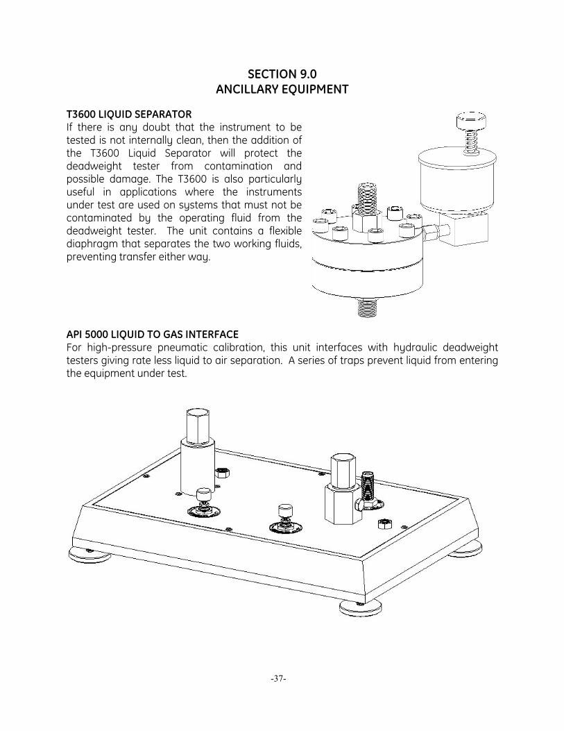
T3600 LIQUID SEPARATOR If there is any doubt that the instrument to be tested is not internally clean, then the addition of the T3600 Liquid Separator will protect the deadweight tester from contamination and possible damage. The T3600 is also particularly useful in applications where the instruments under test are used on systems that must not be contaminated by the operating fluid from the deadweight tester. The unit contains a flexible diaphragm that separates the two working fluids, preventing transfer either way. API 5000 LIQUID TO GAS INTERFACE For high-pressure pneumatic calibration, this unit interfaces with hydraulic deadweight testers giving rate less liquid to air separation. A series of traps prevent liquid from entering the equipment under test.
-37-
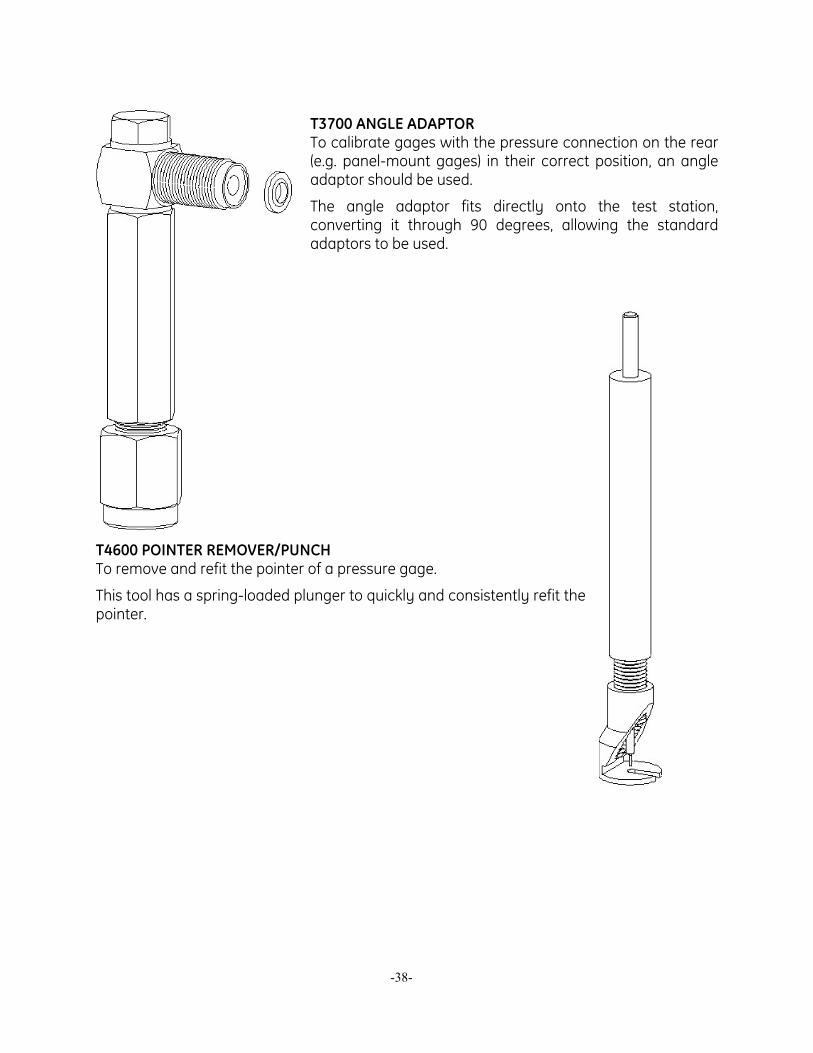
T3700 ANGLE ADAPTOR To calibrate gages with the pressure connection on the rear (e.g. panel-mount gages) in their correct position, an angle adaptor should be used.
The angle adaptor fits directly onto the test station, converting it through 90 degrees, allowing the standard adaptors to be used.
T4600 POINTER REMOVER/PUNCH To remove and refit the pointer of a pressure gage.
This tool has a spring-loaded plunger to quickly and consistently refit the pointer.
-38-
U.S.A 10311 Westpark Drive Houston, TX 77042 T 713 975 0547 F 713 975 6338
imagination at work PMAN-117-1D01, Revision A
January 25, 2005
-39-