models: 1284, 1285, 1286 and 1287 forma class ii, a2 ...€¦ · this manual may result in damage...
TRANSCRIPT
Models: 1284, 1285, 1286 and 1287
Forma Class II, A2Biological Safety Cabinets
Operating and Maintenance ManualManual No: 7021284 Rev. 1
Class II, A2 Biological Safety Cabinets__________________________________________________________________
i
Read This Instruction Manual.
Failure to read, understand and follow the instructions inthis manual may result in damage to the unit, injury to operat-ing personnel, and poor equipment performance.
CAUTION! All internal adjustments and maintenance mustbe performed by qualified service personnel.
Refer to the serial tag on the back of this manual.
The material in this manual is for information purposes only. Thecontents and the product it describes are subject to change with-out notice. Thermo Electron Corporation makes no representa-tions or warranties with respect to this manual. In no event shallThermo be held liable for any damages, direct or incidental, aris-ing out of or related to the use of this manual.
MANUAL NUMBER 7021284
-- -- 6/20/05 Added UV replacement info to Page 9-3 ccs
-- 21497/HD-1424 9/8/04 Added factory-installed anchoring system accessory ccs
-- -- 6/7/04 Clarify test pages ccs
1 22280 4/20/04 Update to incorporate new constricted testing method aks
22197 4/8/04 Blower motor replacement aks
-- 21984 11/13/03 Updated 1284 test sheet (added “four inches above window edge”) ccs
0 21741/HD-1405 8/7/03 Release 6 aks
REV ECR/ECN DATE DESCRIPTION By
Lamps, thermometers and thermoregulatorscontain mercury. Do not put in trash! Recycle ordispose as hazardous waste.
Class II, A2 Biological Safety Cabinets___________________________________________________________________Safety
ii
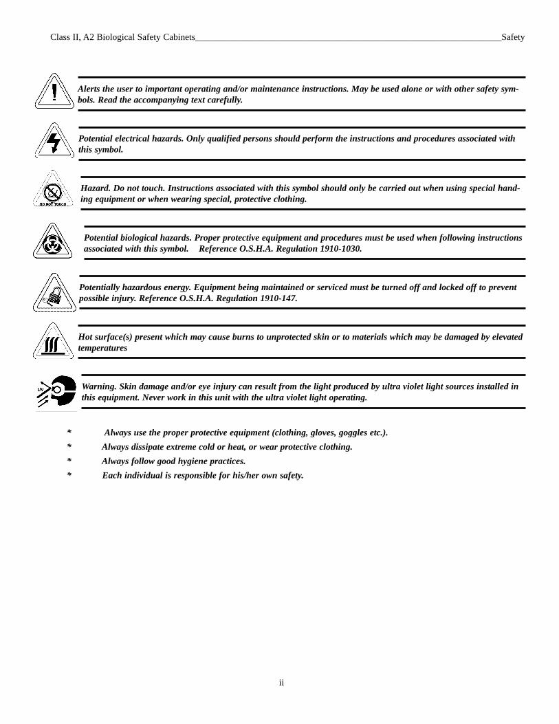
Alerts the user to important operating and/or maintenance instructions. May be used alone or with other safety sym-bols. Read the accompanying text carefully.
Potential electrical hazards. Only qualified persons should perform the instructions and procedures associated withthis symbol.
Hazard. Do not touch. Instructions associated with this symbol should only be carried out when using special hand-ing equipment or when wearing special, protective clothing.
Potential biological hazards. Proper protective equipment and procedures must be used when following instructionsassociated with this symbol. Reference O.S.H.A. Regulation 1910-1030.
Potentially hazardous energy. Equipment being maintained or serviced must be turned off and locked off to preventpossible injury. Reference O.S.H.A. Regulation 1910-147.
Hot surface(s) present which may cause burns to unprotected skin or to materials which may be damaged by elevatedtemperatures
Warning. Skin damage and/or eye injury can result from the light produced by ultra violet light sources installed inthis equipment. Never work in this unit with the ultra violet light operating.
* Always use the proper protective equipment (clothing, gloves, goggles etc.).* Always dissipate extreme cold or heat, or wear protective clothing.* Always follow good hygiene practices.* Each individual is responsible for his/her own safety.
Class II, A2 Biological Safety Cabinets__________________________________________________________________Service
iii
Class II, A2 Biological Safety Cabinets__________________________________________________________Table of Contents
iv
Table of Contents
Section 1 - Receiving . . . . . . . . . . . . . . . . . . . . . . . . . . . .2 - 11.1 Unpacking List . . . . . . . . . . . . . . . . . . . . . . . . . . . . .2 - 1
Section 2 - Introduction . . . . . . . . . . . . . . . . . . . . . . . . . .2 - 12.1 Description . . . . . . . . . . . . . . . . . . . . . . . . . . . . . . . .2 - 12.2 Theory of Operation . . . . . . . . . . . . . . . . . . . . . . . . .2 - 1
Section 3 - Installation . . . . . . . . . . . . . . . . . . . . . . . . . . .3 - 13.1 Location . . . . . . . . . . . . . . . . . . . . . . . . . . . . . . . . . .3 - 13.2 Power Connection . . . . . . . . . . . . . . . . . . . . . . . . . . .3 - 13.3 Plumbing Connection . . . . . . . . . . . . . . . . . . . . . . . .3 - 1
a. Universal Plumbing Option . . . . . . . . . . . . . . . . .3 - 13.4 Exhaust Requirements . . . . . . . . . . . . . . . . . . . . . . .3 - 2
a. Direct Room Exhaust . . . . . . . . . . . . . . . . . . . . . .3 - 2b. External Exhaust System . . . . . . . . . . . . . . . . . . . .3 - 2c. Optional Exhaust Transition . . . . . . . . . . . . . . . . .3 - 2d. Nominal Exhaust Requirements - 4 ft. models . . .3 - 2e. Nominal Exhaust Requirements - 6 ft. models . . .3 - 2
Section 4 - Certification Testing . . . . . . . . . . . . . . . . . . . .4 - 14.1 Locating a Certification Company . . . . . . . . . . . . . . . .4 - 1
Section 5 – Operation . . . . . . . . . . . . . . . . . . . . . . . . . . . .5 - 15.1 Control and Indicating Devices . . . . . . . . . . . . . . . . .5 - 1
Section 6 - General Cautions and Cleaning . . . . . . . . . . .7 - 16.1 Caution Notes . . . . . . . . . . . . . . . . . . . . . . . . . . . . . .7 - 16.2 Cleaning . . . . . . . . . . . . . . . . . . . . . . . . . . . . . . . . . . .7 - 1
Section 7 - Cabinet Start-Up . . . . . . . . . . . . . . . . . . . . . .7 - 17.1 General Recommendations . . . . . . . . . . . . . . . . . . . .7 - 17.2 Use of Auxiliary Equipment in the Cabinet . . . . . . .7 - 17.3 Cabinet Checklist . . . . . . . . . . . . . . . . . . . . . . . . . . .7 - 17.4 Start-Up Procedure . . . . . . . . . . . . . . . . . . . . . . . . . 7 - 1
Section 8 - Troubleshooting . . . . . . . . . . . . . . . . . . . . . . .8 - 18.1 Troubleshooting Guide . . . . . . . . . . . . . . . . . . . . . . .8 - 1
Section 9 - Routine Maintenance . . . . . . . . . . . . . . . . . . .9 - 19.1 Checking the Static Pressure Gauge “Zero” . . . . . . .9 - 19.2 Zeroing the Static Pressure Gauge . . . . . . . . . . . . . .9 - 19.3 Adjusting the Damper . . . . . . . . . . . . . . . . . . . . . . . .9 - 19.4 Biological Safety Cabinet Test Grids . . . . . . . . . . . .9 - 29.5 Blower Control . . . . . . . . . . . . . . . . . . . . . . . . . . . . .9 - 39.6 Receptacle Fuses . . . . . . . . . . . . . . . . . . . . . . . . . . . .9 - 39.7 Ultraviolet Switch Adjustment Procedure . . . . . . . . .9 - 3
Section 10 - Service . . . . . . . . . . . . . . . . . . . . . . . . . . . .10 - 110.1 Replacing the Blower Motor . . . . . . . . . . . . . . . . .10 - 1
a. Reversing the motor wiring . . . . . . . . . . . . . . . .10 - 1b. Replacing the motor . . . . . . . . . . . . . . . . . . . . . .10 - 1
10.2 Replacing the Blower Motor . . . . . . . . . . . . . . . . .10 - 210.3 Replacing the Filters, All Models . . . . . . . . . . . . .10 - 2
Section 11 – Specifications . . . . . . . . . . . . . . . . . . . . . . .11 - 111.1 Model 1284 . . . . . . . . . . . . . . . . . . . . . . . . . . . . . .11 - 111.2 Model 1286 . . . . . . . . . . . . . . . . . . . . . . . . . . . . . .11 - 111.3 Environmental Conditions . . . . . . . . . . . . . . . . . . .11 - 2
Section 12 – Accessories . . . . . . . . . . . . . . . . . . . . . . . . .13 -1
Section 13 - Parts List . . . . . . . . . . . . . . . . . . . . . . . . . . .13 -113.1 Model 1284 . . . . . . . . . . . . . . . . . . . . . . . . . . . . . . .13 -113.2 Model 1286 . . . . . . . . . . . . . . . . . . . . . . . . . . . . . . .13 -213.3 Filter Pressure Drop Conversion . . . . . . . . . . . . . .13 -2
Section 14 - Electrical Schematics . . . . . . . . . . . . . . . . .14 - 1
Section 15 - Warranty . . . . . . . . . . . . . . . . . . . . . . . . . . .15 - 1
Section 1 - Receiving
1.1 Unpacking List
Included with the installation/operation manual are fouridentification index buttons. These buttons may be used to iden-tify the type of service supplied to the service valves. Alsoincluded in a separate bag is the drain valve. Attached to thevalve is a small Allen wrench used for calibrating the StaticPressure Gauge. This Allen wrench should be kept with themanual at all times.
Section 2 - Introduction
2.1 Description
The Models 1284, 1285, 1286 and 1287 are Class II, TypeA2 cabinets. The “Type A2” designation indicates two alterna-tive uses of the cabinet. The unit may be vented directly intothe laboratory room or vented to the outside atmosphere,through an in-house exhaust system. Either usage of the cabinetoffers both personnel and product protection.
The cabinet can be used in low-to-moderate risk environ-ments and is designed to NSF, International Standard #49. Class1, 2, and 3 (low-to-moderate risk) agents are described in the“Biosafety In Microbiological And Biomedical Laboratories”;CDC NIH Publication No. (NIH) 88-8395, 4th Edition, May1999.
The cabinet’s window permits the user to place auxiliaryequipment and research implements in the work area. The workopening must be held to 10 inches during all work procedures.If the window is raised higher than the designated 10 inches,the air barrier at the front of the cabinet will be weakened andcontainment will be seriously impaired.
2.2 Theory of Operation
Clean, filtered air descends through the work zone withapproximately 40% being discharged through the exhaustHEPA filter with the remaining air recirculating through thesupply HEPA filter into the work area. Exhausted air is replacedby room air entering the system through the front access open-ing.
Room air entering the work zone, through the front accessopening, completes the air barrier at the unit face and is respon-sible for the containment properties of the unit. All work mustbe performed beyond the intake grille, on the solid work tray.
Class II, A2 Biological Safety Cabinets______________________________________________________________Introduction
2 - 1
Section 3 - Installation
3.1 Location
Locate the cabinet on a firm, level surface in an area ofminimum temperature changes. The cabinet should be placedaway from disruptive air currents caused by excessive person-nel traffic, air-conditioning or heating ductwork, or laboratorywindows and doors. Proper cabinet location is important, asdrafts disrupt critical airflow characteristics and allow roomcontaminants to enter or escape the cabinet work area.
Where space permits, fourteen inches should be allowed oneach side of the cabinet for maintenance. A twelve-inch heightshould be available from the top of the cabinet to the ceiling.
Place a bubble-type level on the work surface. Adjust theleveling feet until the cabinet is level and the most comfortableworking height is achieved. Ensure that all four leveling feetare fully flush against the floor to prevent vibration.
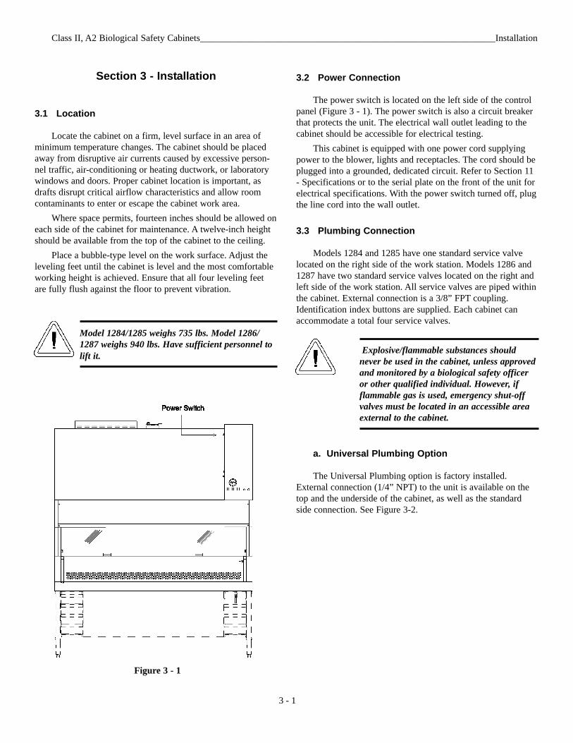
Model 1284/1285 weighs 735 lbs. Model 1286/1287 weighs 940 lbs. Have sufficient personnel tolift it.
3.2 Power Connection
The power switch is located on the left side of the controlpanel (Figure 3 - 1). The power switch is also a circuit breakerthat protects the unit. The electrical wall outlet leading to thecabinet should be accessible for electrical testing.
This cabinet is equipped with one power cord supplyingpower to the blower, lights and receptacles. The cord should beplugged into a grounded, dedicated circuit. Refer to Section 11- Specifications or to the serial plate on the front of the unit forelectrical specifications. With the power switch turned off, plugthe line cord into the wall outlet.
3.3 Plumbing Connection
Models 1284 and 1285 have one standard service valvelocated on the right side of the work station. Models 1286 and1287 have two standard service valves located on the right andleft side of the work station. All service valves are piped withinthe cabinet. External connection is a 3/8” FPT coupling.Identification index buttons are supplied. Each cabinet canaccommodate a total four service valves.
Explosive/flammable substances shouldnever be used in the cabinet, unless approvedand monitored by a biological safety officeror other qualified individual. However, ifflammable gas is used, emergency shut-offvalves must be located in an accessible areaexternal to the cabinet.
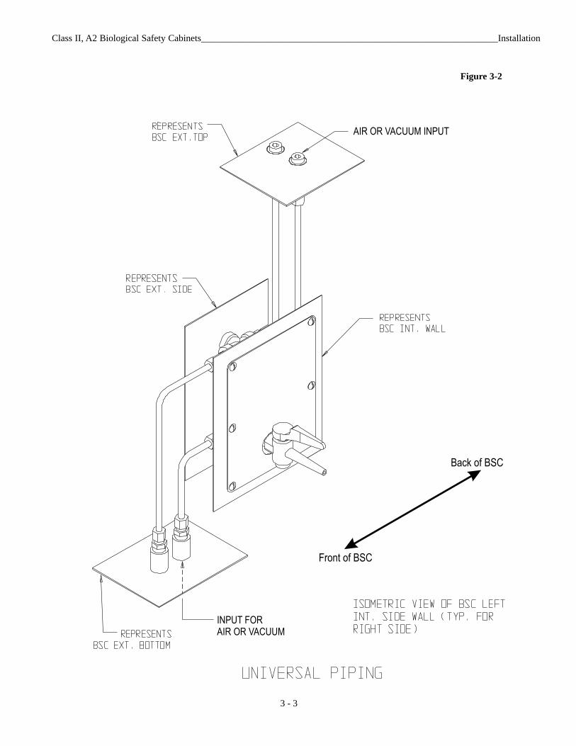
a. Universal Plumbing Option
The Universal Plumbing option is factory installed.External connection (1/4” NPT) to the unit is available on thetop and the underside of the cabinet, as well as the standardside connection. See Figure 3-2.
Class II, A2 Biological Safety Cabinets_______________________________________________________________Installation
3 - 1
Figure 3 - 1
Class II, A2 Biological Safety Cabinets_______________________________________________________________Installation
3 - 2
3.4 Exhaust Requirements
Filtered air from the cabinet may be exhausted directly intothe room or vented to the outside through an external exhaustsystem. Consult a biological safety officer or other qualifiedindividual for cabinet-type exhaust requirements. Refer to NSFStandard, NSF 49-2002, Annex E.
a. Direct Room Exhaust
A cardboard cover plate is shipped under the exhaust filterguard. It must be removed before the unit is placed into service.Locate the exhaust filter guard on the top of the cabinet.Remove the guard and discard the cardboard. Secure the exhaustfilter guard as previously.
b. External Exhaust System (For Class II Type A2)
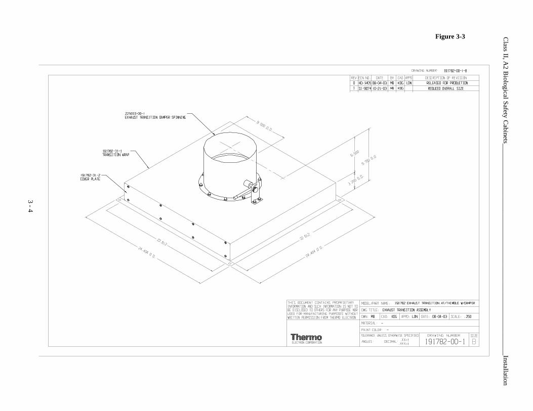
If an external exhaust system is needed, use a canopy (thim-ble) connection (Figure 3-3). When the cabinet is certified,check the opening in the canopy to ensure inward airflow, usinga smoke stick. Ensure proper air balance at the front accessopening for adequate containment. Verify that the buildingexhaust system is sized to exhaust 30% more air than the cabinetexhausts. Models 1284 and 1285 exhaust an air volume of 358-391 CFM. Models 1286 and 1287 exhaust an air volume of 531-580 CFM.
IMPORTANT! The exhaust air must be drawnfrom the cabinet through a dedicated exhaust sys-tem (only one BSC per exhaust system). Theexhaust system may be connected to the collar(optional exhaust transition) located on the top ofthe unit.
The exhaust system should have safeguardsagainst exhaust failure. It is required that a bio-logical safety officer, industrial hygienist or otherqualified individual review the agents and chemi-cals used inside the cabinet to determine if addi-tional filtration treatment is necessary before vent-ing to the atmosphere.
c. Optional Exhaust Transition
Canopy/Thimble style - P/N 191570 Release 1-5 units,P/N 191782 Release 6. Refer to the unit serial tag to determinerelease level.
d. Nominal Exhaust Requirements - 4 foot models
Nominal 375 CFM Direct method and calculated method.Nominal 487 CFM, when sizing to exhaust 30% more air(than the cabinet exhausts)
e. Nominal Exhaust Requirements - 6 foot models
Nominal 556 CFM Nominal 722 CFM, when sizing to exhaust 30% more air(than the cabinet exhausts)
Class II, A2 Biological Safety Cabinets_______________________________________________________________Installation
3 - 3
INPUT FOR
AIR OR VACUUM
AIR OR VACUUM INPUT
Back of BSC
Front of BSC
Figure 3-2
Class II, A
2 Biological Safety C
abinets_______________________________________________________________Installation
3 - 4
Figure 3-3
Class II, A2 Biological Safety Cabinets_______________________________________________________________Installation
Section 4 - Certification Testing
Service and certification must be performed byqualified personnel.
4.1 Locating a Certification Company
Biological safety cabinet certification consists of a series oftests designed to verify that the cabinet is performing withinoperating parameters established by the manufacturer.
To assure that a biological safety cabinet is operating asintended, each cabinet should be field-tested at the time ofinstallation and at least annually thereafter. Cabinets should bere-certified whenever HEPA filters are changed, internal mainte-nance is performed, or is relocated.
Three industry-related organizations maintain lists of com-panies and individuals who are active in the certification indus-try. You may contact these organizations at the addresses listedbelow.
NSF International (NSF) and International Air FiltrationCertifiers Association (IAFCA) sponsor certifier accreditationprograms. Accredited certifiers have demonstrated proficiency attesting biological safety cabinets by successfully completingwritten and/or practical examinations.
Biohazard Cabinet Field Certifier ProgramNSF InternationalPO Box 130140789 N. Dixboro RdAnn Arbor, MI 48113-0140Telephone (734) 769-8010 Or (800) NSF-MARKFax (734) 769-0109http://www.nsf.org/Certified/Biohazard-Certifier
IAFCAPO Box 12155Columbus, OH 43212Telephone (888) 679-1904Fax (614) 486-1108http://www.iafca.com/certifier.html
The Controlled Environment Testing Association (CETA) isa trade association devoted to promoting and developing qualityassurance within the controlled environment testing industry. Alist of active members is available by contacting the organiza-tion.
Controlled Environment Testing Association1500 Sunday DriveSuite 102Raleigh, NC 27607Telephone (919) 787-5181Fax (919) 787-4916http://www.cetainternational.org/members/corp_indiv.htm
For your convenience we have included a partial list ofagencies that perform certification on our website. SelectCertification Companies located under the Services and Supportheading at www.thermo.com/forma. If you do not find someonelisted in your area, please contact the Technical ServicesDepartment for additional references.
Note: Unless certification was expressly called for in the specifi-cation, quotes and/or purchase order, the cost for this on-sitetesting is to be paid for by the customer.
4 - 1
Section 5 – Operation
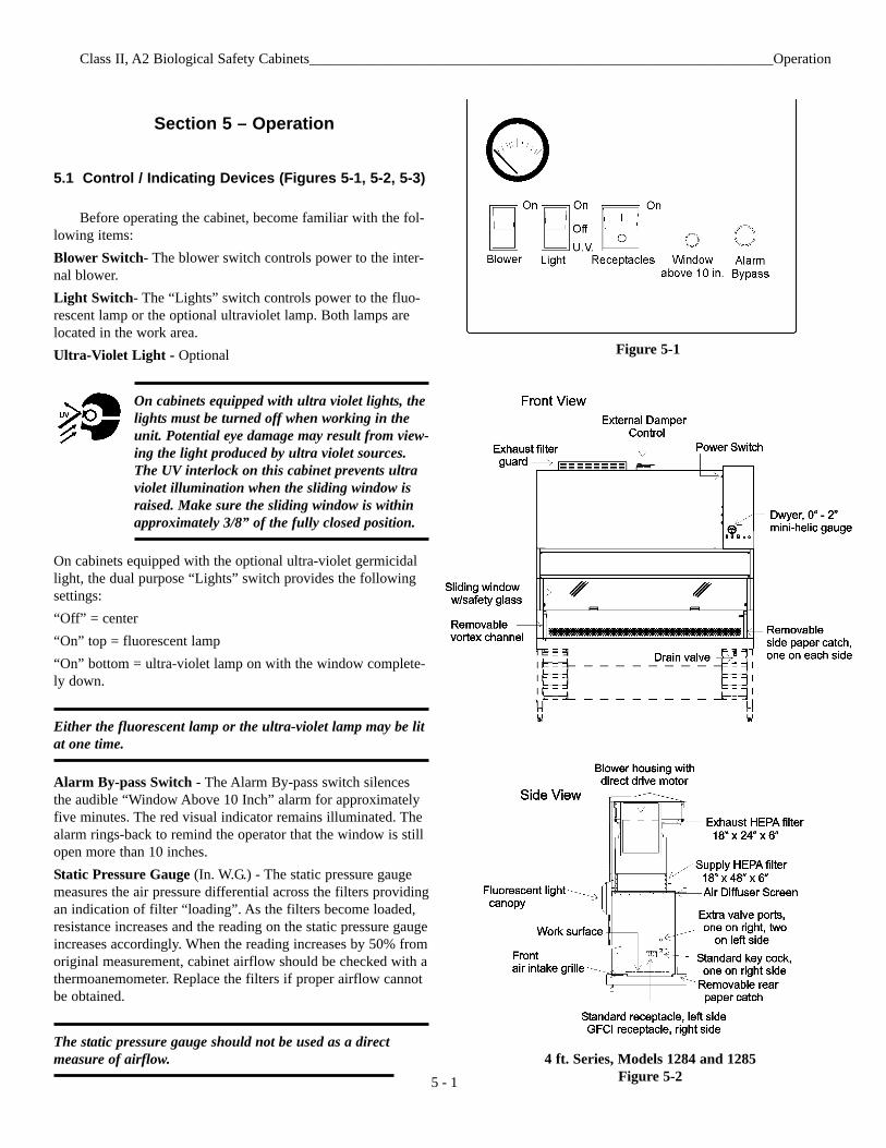
5.1 Control / Indicating Devices (Figures 5-1, 5-2, 5-3)
Before operating the cabinet, become familiar with the fol-lowing items:Blower Switch- The blower switch controls power to the inter-nal blower.Light Switch- The “Lights” switch controls power to the fluo-rescent lamp or the optional ultraviolet lamp. Both lamps arelocated in the work area.Ultra-Violet Light - Optional
On cabinets equipped with ultra violet lights, thelights must be turned off when working in theunit. Potential eye damage may result from view-ing the light produced by ultra violet sources.The UV interlock on this cabinet prevents ultraviolet illumination when the sliding window israised. Make sure the sliding window is withinapproximately 3/8” of the fully closed position.
On cabinets equipped with the optional ultra-violet germicidallight, the dual purpose “Lights” switch provides the followingsettings: “Off” = center“On” top = fluorescent lamp“On” bottom = ultra-violet lamp on with the window complete-ly down.
Either the fluorescent lamp or the ultra-violet lamp may be litat one time.
Alarm By-pass Switch - The Alarm By-pass switch silencesthe audible “Window Above 10 Inch” alarm for approximatelyfive minutes. The red visual indicator remains illuminated. Thealarm rings-back to remind the operator that the window is stillopen more than 10 inches. Static Pressure Gauge (In. W.G.) - The static pressure gaugemeasures the air pressure differential across the filters providingan indication of filter “loading”. As the filters become loaded,resistance increases and the reading on the static pressure gaugeincreases accordingly. When the reading increases by 50% fromoriginal measurement, cabinet airflow should be checked with athermoanemometer. Replace the filters if proper airflow cannotbe obtained.
The static pressure gauge should not be used as a directmeasure of airflow.
Class II, A2 Biological Safety Cabinets________________________________________________________________Operation
Figure 5-1
4 ft. Series, Models 1284 and 1285Figure 5-25 - 1
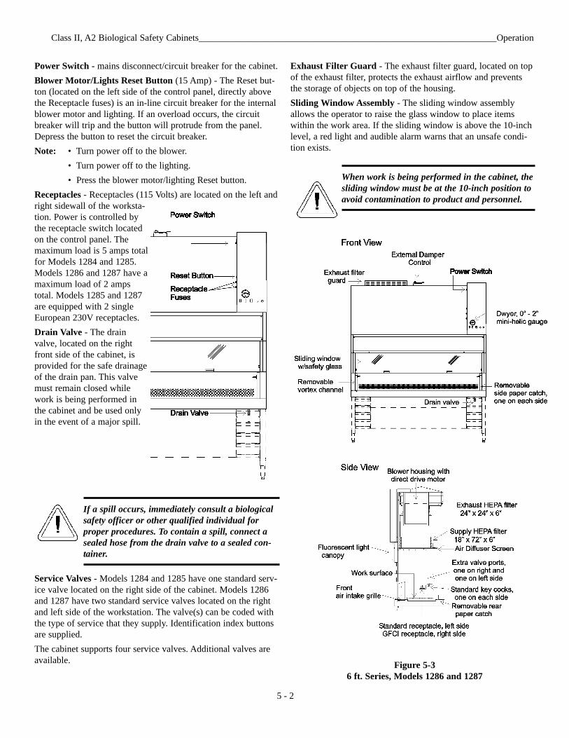
Power Switch - mains disconnect/circuit breaker for the cabinet.Blower Motor/Lights Reset Button (15 Amp) - The Reset but-ton (located on the left side of the control panel, directly abovethe Receptacle fuses) is an in-line circuit breaker for the internalblower motor and lighting. If an overload occurs, the circuitbreaker will trip and the button will protrude from the panel.Depress the button to reset the circuit breaker.Note: • Turn power off to the blower.
• Turn power off to the lighting.• Press the blower motor/lighting Reset button.
Receptacles - Receptacles (115 Volts) are located on the left andright sidewall of the worksta-tion. Power is controlled bythe receptacle switch locatedon the control panel. Themaximum load is 5 amps totalfor Models 1284 and 1285.Models 1286 and 1287 have amaximum load of 2 ampstotal. Models 1285 and 1287are equipped with 2 singleEuropean 230V receptacles. Drain Valve - The drainvalve, located on the rightfront side of the cabinet, isprovided for the safe drainageof the drain pan. This valvemust remain closed whilework is being performed inthe cabinet and be used onlyin the event of a major spill.
If a spill occurs, immediately consult a biologicalsafety officer or other qualified individual forproper procedures. To contain a spill, connect asealed hose from the drain valve to a sealed con-tainer.
Service Valves - Models 1284 and 1285 have one standard serv-ice valve located on the right side of the cabinet. Models 1286and 1287 have two standard service valves located on the rightand left side of the workstation. The valve(s) can be coded withthe type of service that they supply. Identification index buttonsare supplied.The cabinet supports four service valves. Additional valves areavailable.
Exhaust Filter Guard - The exhaust filter guard, located on topof the exhaust filter, protects the exhaust airflow and preventsthe storage of objects on top of the housing.Sliding Window Assembly - The sliding window assemblyallows the operator to raise the glass window to place itemswithin the work area. If the sliding window is above the 10-inchlevel, a red light and audible alarm warns that an unsafe condi-tion exists.
When work is being performed in the cabinet, thesliding window must be at the 10-inch position toavoid contamination to product and personnel.
Class II, A2 Biological Safety Cabinets________________________________________________________________Operation
5 - 2
Figure 5-36 ft. Series, Models 1286 and 1287
Class II, A2 Biological Safety Cabinets_______________________________General Cautions and Cleaning / Cabinet Start-Up
Section 6 - General Cautions and Cleaning
6.1 Caution Notes
• Following initial installation, the unit must be thoroughlytested and certified.
• All activities to be performed within the cabinet should beapproved by a biological safety officer or other qualifiedindividual.
• Since the HEPA filters remove particulates only (not gas),explosive/flammable substances should never be used inthe cabinet, unless approved and monitored by a biologicalsafety officer or other qualified individual.
• If the cabinet is to be used for biological or toxicologicalapplications, a biological safety officer or other qualifiedindividual must monitor it.
• If the unit needs to be serviced, it must be decontaminatedto protect service personnel. After servicing, the cabinetmust be recertified by a qualified certifying agency.
• None of the perforations in the work area may be coveredor blocked, as airflow will be disrupted and contaminationmay occur.
• Paper catches should always be kept free of debris.
6.2 Cleaning
For general cleaning of dirt, dust and fingermarks, use ageneral household (non-abrasive) cleaner with a soft cloth orsponge and warm water. Cleaning should always be followedby rinsing with clean water and wiping the surface completelydry.
Before each use, the work surface, interior walls and interi-or surface of the window should be wiped with an appropriatedisinfectant.
At the end of the work day, decontaminate the work sur-face, cabinet sides and back, and interior of the glass.
Alcohol, even a 70% solution, is volatile andflammable Use it only in a well ventilated areathat is free from open flame. If any component iscleaned with alcohol, do not expose the compo-nent to open flame or other possible hazard.Allow the alcohol to fully dry before turningpower on.
Do not use strong alkaline or caustic agents.Stainless steel is corrosion-resistant, not corro-sion-proof. Do not use solutions of sodiumhypochlorite (bleach) as they may also cause pit-ting and rusting.
Section 7 - Cabinet Start-Up
7.1 General Recommendations
• Keep movement in the room to a minimum when the cabi-net is in use.
• Keep all laboratory doors closed to prevent drafts that maydisturb critical airflow.
• Pre-plan cabinet use and place everything needed in thecabinet so that nothing passes through the air barrier (in orout) during the procedure.
• Practice good aseptic technique to ensure safe use of thecabinet.
• If a spill occurs, clean it up immediately. Decontaminatethe work area and all affected equipment.
• Do not cover or block the exhaust grille.• Do not cover or block any perforations (air holes) in the
work area.
7.2 Use of Auxiliary Equipment in the Cabinet
Use auxiliary equipment in the cabinet only if proper pre-cautions are taken. Appliances used in the work area will causeturbulence, disturb the airflow and need to be carefully man-aged. The equipment should be placed at the rear of the work-space where it will have minimal effect.
A blender may be used in the cabinet. But because of theamount of aerosol it produces and the turbulence it causes, it isrecommended that it be removed from the cabinet as soon aspossible.
7.3 Cabinet Checklist
1. Verify that the Drain valve is closed (the handle turnedhorizontal).
2. Verify that all service valves are closed. 3. Verify that the cardboard exhaust filter protector has
been removed.
7.4 Start-Up Procedure
1. Turn the power switch on.2. Turn the light on.3. Check the intake and exhaust grilles to ensure they are
not blocked.4. Turn the blower on.5. Place everything needed into the cabinet.6. Place the viewing window at 10 inches.7 - 1
Class II, A2 Biological Safety Cabinets___________________________________________________________Troubleshooting
8 - 1
Section 8 - Troubleshooting
8.1 Troubleshooting Guide
The following is a guide to troubleshooting the system. If acontaminated area of the cabinet must be entered to determineand/or resolve the source of a particular problem, the cabinetmust first be decontaminated.
Servicing of the unit must be performed by quali-fied service personnel.
Problem 1: Airflow in the cabinet work area and through theexhaust filter is inadequate.Possible causes:
• Exhaust filter is blocked by laboratory materials or the pro-tective shipping cover.
• If the biological safety cabinet is connected to an exhaustsystem, there may be inadequate exhaust suction or backpressure in the duct system. The system must be rebalancedto handle the correct air volume. A biological safety officershould be consulted.
• Low voltage is being applied to the blower motor.• Blower motor or speed control is defective.• Supply HEPA filter and Exhaust HEPA filter may be
loaded. Decontaminate the unit and replace both HEPA fil-ters.
Before any maintenance work is performed inthe biological safety cabinet, the unit must firstbe decontaminated.
Problem 2: Ultra violet light malfunctionPossible causes:
• Make sure the sliding window is within approximately 3/8”of the fully closed position.
• Check lamp pins and socket ends for contact.• U.V. lamp is defective.• Starter is defective for the UV light.• Check UV interlock switch adjustment.
Problem 3: Fluorescent light malfunctionPossible causes:
• Check lamp pins and socket ends for contact.• Lamp is defective.
Problem 4: Loud screeching noisePossible causes:
• Bearings are bad in the motor blower assembly.• Blower wheel is rubbing against the housing.
Class II, A2 Biological Safety Cabinets_______________________________________________________Routine Maintenance
Section 9 - Routine Maintenance
Before any maintenance work is performed inthe biological safety cabinet, the unit must firstbe decontaminated.
9.1 Checking the Static Pressure Gauge “Zero”
Note: In order to provide an accurate reading, the indicatingneedle of the static pressure gauge should be precisely at zerowhen the cabinet is shut off. If the cabinet is connected to acentral exhaust system, the exhaust system must also be shutoff.
Following HEPA filter replacement, the static pressuregauge should be checked for zero when the cabinet is shut off.(refer to Section 9.2). When the cabinet is started up and properairflow balance has been reached, the reading on the gaugeshould be recorded. This initial reading will serve as a baselineindication of subsequent filter loading. When the readingincreases by approximately 50%, the airflow balance shouldagain be checked. Replacement of the filters may be required.
9.2 Zeroing the Static Pressure Gauge
1. Turn the cabinet off.2. Remove the front cover from the static pressure gauge
by grasping the front cover and turning it counterclock-wise.
3. Locate the Allen-type adjustment screw beside the gaugeneedle.
4. Turn the adjustment screw counterclockwise to lowerthe reading; clockwise to raise it.
9.3 Adjusting the Damper
Since the HEPA filter resistance may vary from filter to fil-ter (even filters of the same size), a damper has been installedin the cabinet exhaust system for maintaining proper airflowbalance. The purpose of the damper is to regulate the amount ofexhaust air, intake velocity and supply velocity. The damper hasbeen preset at the factory and should not be readjusted unlessthe proper velocities cannot be obtained.
Adjustments must be made by qualified personnelonly!
1. Layout test grids (refer to Section 9.4).2. Start-up the cabinet and allow it to run for at least twen-
ty minutes.3. Take airflow measurements. If airflow specifications are
not sufficient, open the control panel and check the volt-age on the power switch.
Note: Airflow measurements and voltages are recorded at thefactory with the cabinet connected to the appropriate AC powersupply.
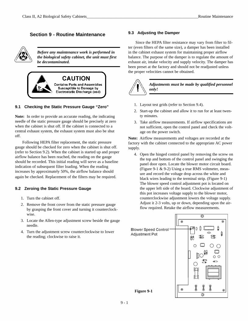
4. Open the hinged control panel by removing the screw onthe top and bottom of the control panel and swinging thepanel door open. Locate the blower motor circuit board.(Figure 9-1 & 9-2) Using a true RMS voltmeter, meas-ure and record the voltage drop across the white andblack wires leading to the terminal strip. (Figure 9-1)The blower speed control adjustment pot is located onthe upper left side of the board. Clockwise adjustment ofthis pot increases voltage supply to the blower motor,counterclockwise adjustment lowers the voltage supply.Adjust it 2-3 volts, up or down, depending upon the air-flow required. Retake the airflow measurements.
Figure 9-1
9 - 1
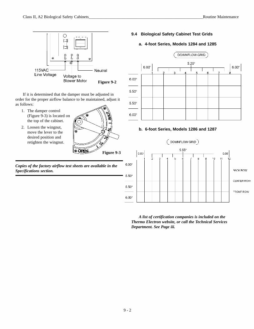
If it is determined that the damper must be adjusted inorder for the proper airflow balance to be maintained, adjust itas follows:
1. The damper control(Figure 9-3) is located onthe top of the cabinet.
2. Loosen the wingnut,move the lever to thedesired position andretighten the wingnut.
Copies of the factory airflow test sheets are available in theSpecifications section.
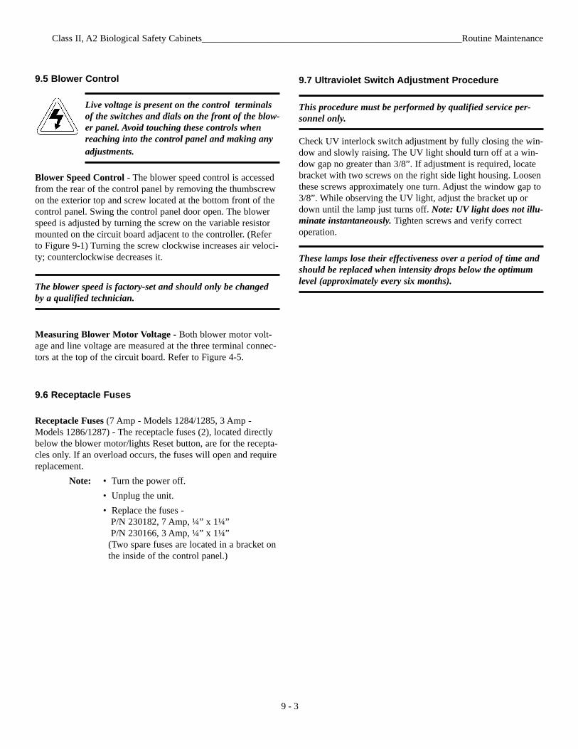
9.4 Biological Safety Cabinet Test Grids
a. 4-foot Series, Models 1284 and 1285
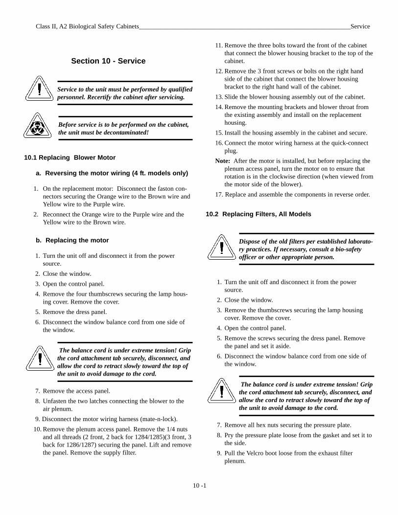
b. 6-foot Series, Models 1286 and 1287
A list of certification companies is included on theThermo Electron website, or call the Technical ServicesDepartment. See Page iii.
Class II, A2 Biological Safety Cabinets_______________________________________________________Routine Maintenance
9 - 2
Figure 9-2
Figure 9-3
9.5 Blower Control
Live voltage is present on the control terminalsof the switches and dials on the front of the blow-er panel. Avoid touching these controls whenreaching into the control panel and making anyadjustments.
Blower Speed Control - The blower speed control is accessedfrom the rear of the control panel by removing the thumbscrewon the exterior top and screw located at the bottom front of thecontrol panel. Swing the control panel door open. The blowerspeed is adjusted by turning the screw on the variable resistormounted on the circuit board adjacent to the controller. (Referto Figure 9-1) Turning the screw clockwise increases air veloci-ty; counterclockwise decreases it.
The blower speed is factory-set and should only be changedby a qualified technician.
Measuring Blower Motor Voltage - Both blower motor volt-age and line voltage are measured at the three terminal connec-tors at the top of the circuit board. Refer to Figure 4-5.
9.6 Receptacle Fuses
Receptacle Fuses (7 Amp - Models 1284/1285, 3 Amp -Models 1286/1287) - The receptacle fuses (2), located directlybelow the blower motor/lights Reset button, are for the recepta-cles only. If an overload occurs, the fuses will open and requirereplacement.
Note: • Turn the power off.• Unplug the unit.• Replace the fuses -
P/N 230182, 7 Amp, ¼” x 1¼”P/N 230166, 3 Amp, ¼” x 1¼”
(Two spare fuses are located in a bracket on the inside of the control panel.)
Class II, A2 Biological Safety Cabinets_______________________________________________________Routine Maintenance
9 - 3
9.7 Ultraviolet Switch Adjustment Procedure
This procedure must be performed by qualified service per-sonnel only.
Check UV interlock switch adjustment by fully closing the win-dow and slowly raising. The UV light should turn off at a win-dow gap no greater than 3/8”. If adjustment is required, locatebracket with two screws on the right side light housing. Loosenthese screws approximately one turn. Adjust the window gap to3/8”. While observing the UV light, adjust the bracket up ordown until the lamp just turns off. Note: UV light does not illu-minate instantaneously. Tighten screws and verify correctoperation.
These lamps lose their effectiveness over a period of time andshould be replaced when intensity drops below the optimumlevel (approximately every six months).
Section 10 - Service
Service to the unit must be performed by qualifiedpersonnel. Recertify the cabinet after servicing.
Before service is to be performed on the cabinet,the unit must be decontaminated!
10.1 Replacing Blower Motor
a. Reversing the motor wiring (4 ft. models only)
1. On the replacement motor: Disconnect the faston con-nectors securing the Orange wire to the Brown wire andYellow wire to the Purple wire.
2. Reconnect the Orange wire to the Purple wire and theYellow wire to the Brown wire.
b. Replacing the motor
1. Turn the unit off and disconnect it from the powersource.
2. Close the window.3. Open the control panel.4. Remove the four thumbscrews securing the lamp hous-
ing cover. Remove the cover.5. Remove the dress panel.6. Disconnect the window balance cord from one side of
the window.
The balance cord is under extreme tension! Gripthe cord attachment tab securely, disconnect, andallow the cord to retract slowly toward the top ofthe unit to avoid damage to the cord.
7. Remove the access panel.8. Unfasten the two latches connecting the blower to the
air plenum. 9. Disconnect the motor wiring harness (mate-n-lock).
10. Remove the plenum access panel. Remove the 1/4 nutsand all threads (2 front, 2 back for 1284/1285)(3 front, 3back for 1286/1287) securing the panel. Lift and removethe panel. Remove the supply filter.
Class II, A2 Biological Safety Cabinets_________________________________________________________________Service
10 -1
11. Remove the three bolts toward the front of the cabinetthat connect the blower housing bracket to the top of thecabinet.
12. Remove the 3 front screws or bolts on the right handside of the cabinet that connect the blower housingbracket to the right hand wall of the cabinet.
13. Slide the blower housing assembly out of the cabinet.14. Remove the mounting brackets and blower throat from
the existing assembly and install on the replacementhousing.
15. Install the housing assembly in the cabinet and secure. 16. Connect the motor wiring harness at the quick-connect
plug.Note: After the motor is installed, but before replacing the
plenum access panel, turn the motor on to ensure thatrotation is in the clockwise direction (when viewed fromthe motor side of the blower).
17. Replace and assemble the components in reverse order.
10.2 Replacing Filters, All Models
Dispose of the old filters per established laborato-ry practices. If necessary, consult a bio-safetyofficer or other appropriate person.
1. Turn the unit off and disconnect it from the powersource.
2. Close the window.3. Remove the thumbscrews securing the lamp housing
cover. Remove the cover.4. Open the control panel.5. Remove the screws securing the dress panel. Remove
the panel and set it aside.6. Disconnect the window balance cord from one side of
the window.
The balance cord is under extreme tension! Gripthe cord attachment tab securely, disconnect, andallow the cord to retract slowly toward the top ofthe unit to avoid damage to the cord.
7. Remove all hex nuts securing the pressure plate.8. Pry the pressure plate loose from the gasket and set it to
the side.9. Pull the Velcro boot loose from the exhaust filter
plenum.
Class II, A2 Biological Safety Cabinets__________________________________________________________________Service
10 -2
10. Release the two latches securing the supply plenum tothe blower housing.
11. Disconnect the vinyl tubing that connects the Mag gaugeto the plenum.
12. Remove the hex nuts (4 on the four-foot models, 6 onthe six-foot models), springs, washers and hold-downbrackets securing the plenum.
13. Remove the front filter hold-down studs (2 on the four-foot models, 3 on the six-foot models) in front of theplenum.
14. Slide the plenum from the cabinet.15. Remove the supply filter and clean the filter mounting
surface.16. Loosen - do not remove, the four bolts, springs and
washers that secure the exhaust filter.17. Slide the exhaust filter out, clean the filter mounting sur-
face and install the new filter, ensuring that the gasket ison the top.
18. Tighten the hex nuts to secure the new exhaust filter inposition.
19. Install the new supply filter with the gasket side down.20. Reinstall the supply plenum and assemble the compo-
nents in reverse order.The cabinet must be recertified after filter replacement.
Assembly Notes:
• Latches connecting the plenum to the blower housing havea safety lock that must be released prior to opening thelatch.
• When tightening the filter hold-down nuts, the springsshould be compressed from 1/2 to 3/4 of their originalheight.
• Ensure that the vinyl tubing from the Mag gauge is recon-nected to the supply plenum.
• The Velcro connection on the exhaust boot must be smoothwith no gaps or loose spots to ensure proper sealing.
Class II, A2 Biological Safety Cabinets___________________________________________________________Specifications
11 -1
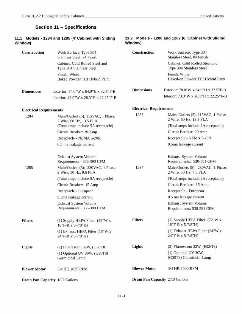
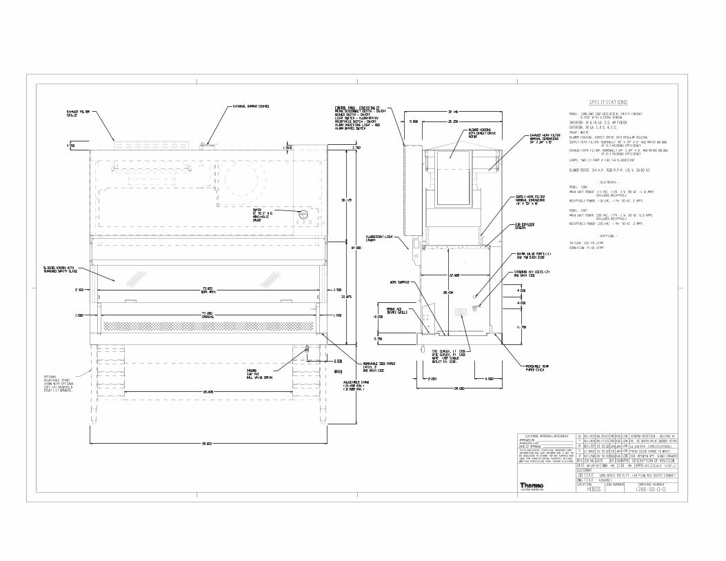
11.2 Models - 1286 and 1287 (6’ Cabinet with SlidingWindow)
Construction Work Surface: Type 304 Stainless Steel, #4 FinishCabinet: Cold Rolled Steel and Type 304 Stainless SteelFinish: White Baked-on Powder TCI Hybrid Paint
Dimensions Exterior: 78.0”W x 64.0”H x 32.5”F-BInterior: 73.0”W x 28.3”H x 22.25”F-B
Electrical Requirements1286 Main/ Outlets (5): 115VAC, 1 Phase,
2 Wire, 60 Hz, 13.8 FLA(Total amps include 2A receptacle)Circuit Breaker: 20 AmpReceptacle - NEMA 5-20R0.5ma leakage current
Exhaust System Volume Requirements: 530-581 CFM
1287 Main/Outlets (5): 230VAC, 1 Phase,2 Wire, 50 Hz, 7.5 FLA(Total amps include 2A receptacle)Circuit Breaker: 15 AmpReceptacle - European0.5 ma leakage currentExhaust System Volume Requirements: 530-581 CFM
Filters (1) Supply HEPA Filter (72”W x 18”F-B x 5-7/8”H)(1) Exhaust HEPA Filter (24”W x 24”F-B x 5-7/8”H)
Lights (2) Fluorescent 32W, (F32/T8)(1) Optional UV 30W, (G30T8) Germicidal Lamp
Blower Motor 3/4 HP, 1500 RPM
Drain Pan Capacity 27.0 Gallons
Section 11 – Specifications
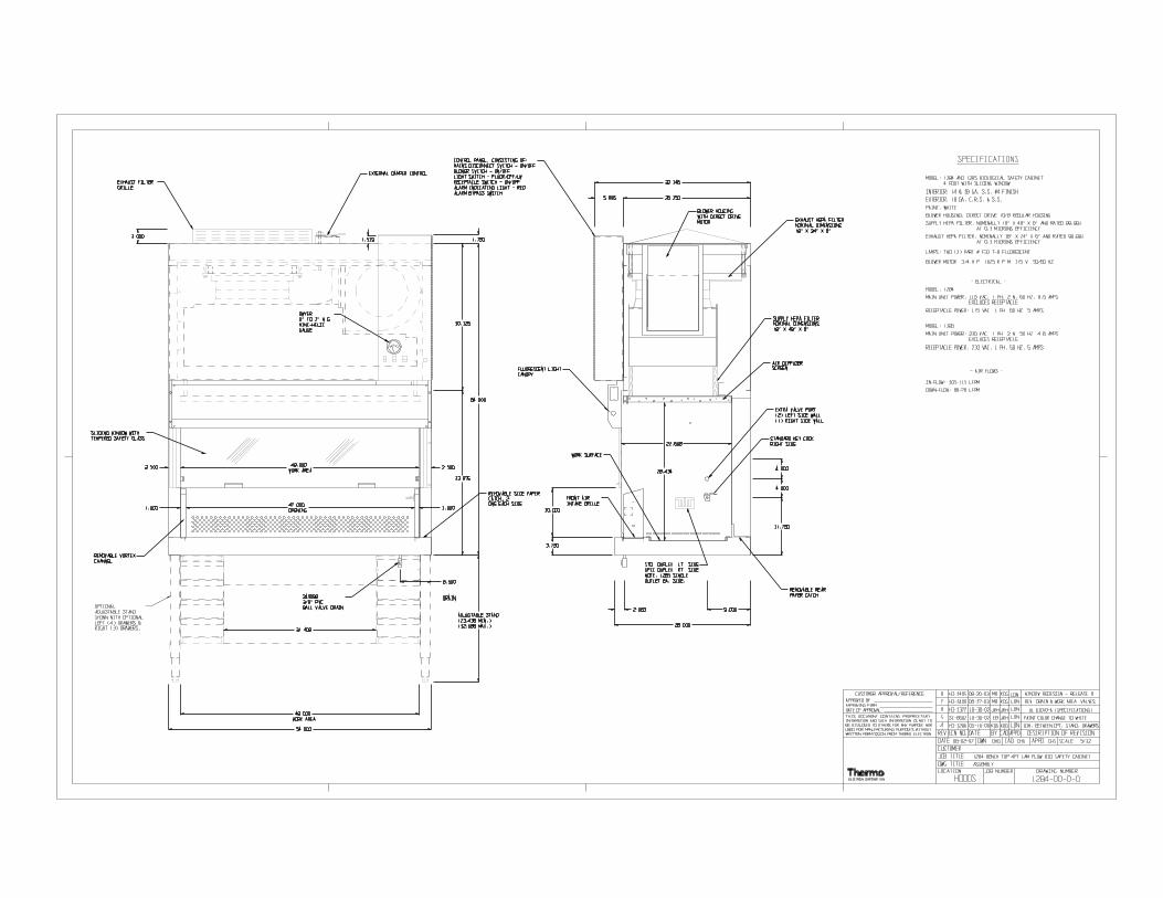
11.1 Models - 1284 and 1285 (4’ Cabinet with SlidingWindow)
Construction Work Surface: Type 304 Stainless Steel, #4 FinishCabinet: Cold Rolled Steel and Type 304 Stainless SteelFinish: WhiteBaked Powder TCI Hybrid Paint
Dimensions Exterior: 54.0”W x 64.0”H x 32.5”F-BInterior: 49.0”W x 28.3”H x 22.25”F-B
Electrical Requirements1284 Main/Outlets (5): 115VAC, 1 Phase,
2 Wire, 60 Hz, 13.5 FLA(Total amps include 5A receptacle)Circuit Breaker: 20 AmpReceptacle - NEMA 5-20R0.5 ma leakage current
Exhaust System Volume Requirements: 356-390 CFM
1285 Main/Outlets (5): 230VAC, 1 Phase,2 Wire, 50 Hz, 9.6 FLA(Total amps include 5A receptacle)Circuit Breaker: 15 AmpReceptacle - European0.5ma leakage currentExhaust System Volume Requirements: 356-390 CFM
Filters (1) Supply HEPA Filter (48”W x 18”F-B x 5-7/8”H)(1) Exhaust HEPA Filter (18”W x 24”F-B x 5-7/8”H)
Lights (2) Fluorescent 32W, (F32/T8)(1) Optional UV 30W, (G30T8) Germicidal Lamp
Blower Motor 3/4 HP, 1625 RPM
Drain Pan Capacity 18.7 Gallons
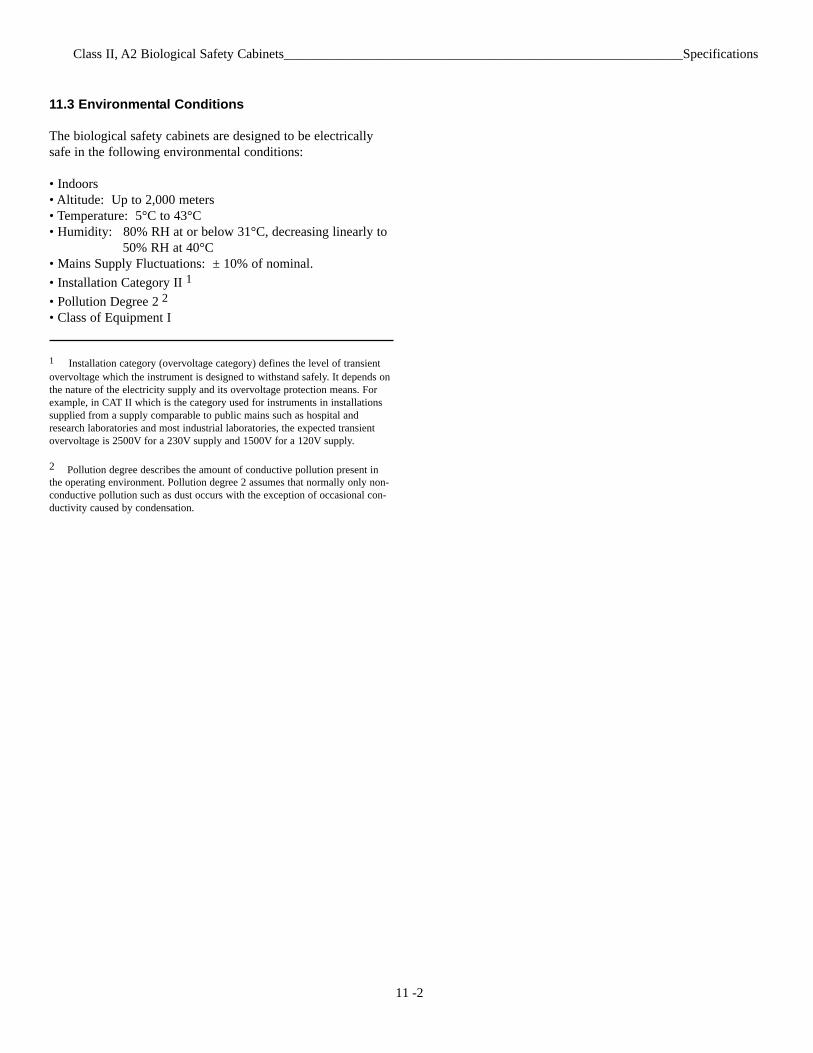
11.3 Environmental Conditions
The biological safety cabinets are designed to be electricallysafe in the following environmental conditions:
• Indoors• Altitude: Up to 2,000 meters• Temperature: 5°C to 43°C• Humidity: 80% RH at or below 31°C, decreasing linearly to
50% RH at 40°C• Mains Supply Fluctuations: ± 10% of nominal. • Installation Category II 1
• Pollution Degree 2 2
• Class of Equipment I
1 Installation category (overvoltage category) defines the level of transientovervoltage which the instrument is designed to withstand safely. It depends onthe nature of the electricity supply and its overvoltage protection means. Forexample, in CAT II which is the category used for instruments in installationssupplied from a supply comparable to public mains such as hospital andresearch laboratories and most industrial laboratories, the expected transientovervoltage is 2500V for a 230V supply and 1500V for a 120V supply.
2 Pollution degree describes the amount of conductive pollution present inthe operating environment. Pollution degree 2 assumes that normally only non-conductive pollution such as dust occurs with the exception of occasional con-ductivity caused by condensation.
Class II, A2 Biological Safety Cabinets____________________________________________________________Specifications
11 -2
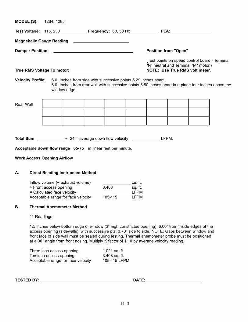
MODEL (S): 1284, 1285
Test Voltage: 115, 230 Frequency: 60, 50 Hz FLA:
Magnehelic Gauge Reading
Damper Position: Position from "Open"
(Test points on speed control board - Terminal "N" neutral and Terminal "M" motor.)
True RMS Voltage To motor: NOTE: Use True RMS volt meter.
Velocity Profile: 6.0 Inches from side with successive points 5.29 inches apart.6.0 Inches from rear wall with successive points 5.50 inches apart in a plane four inches above the window edge.
Rear Wall
Total Sum ÷ 24 = average down flow velocity LFPM.
Acceptable down flow range 65-75 in linear feet per minute.
Work Access Opening Airflow
A. Direct Reading Instrument Method
Inflow volume (~ exhaust volume) cu. ft.÷ Front access opening 3.403 sq. ft.= Calculated face velocity LFPMAcceptable range for face velocity 105-115 LFPM
B. Thermal Anemometer Method
11 Readings
1.5 inches below bottom edge of window (3” high constricted opening), 6.00” from inside edges of the access opening (sidewalls), with successive pts. 3.70” side to side. NOTE: Gaps between window andfront face of side wall must be sealed during testing. Thermal anemometer probe must be positioned at a 30° angle from front nosing. Multiply K factor of 1.10 by average velocity reading.
Three inch access opening 1.021 sq. ft.Ten inch access opening 3.403 sq. ft.Acceptable range for face velocity 105-115 LFPM
TESTED BY: DATE:
11 -3
11 -4
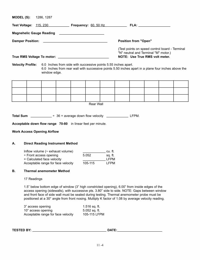
MODEL (S): 1286, 1287
Test Voltage: 115, 230 Frequency: 60, 50 Hz FLA:
Magnehelic Gauge Reading
Damper Position: Position from "Open"
(Test points on speed control board - Terminal "N" neutral and Terminal "M" motor.)
True RMS Voltage To motor: NOTE: Use True RMS volt meter.
Velocity Profile: 6.0 Inches from side with successive points 5.55 inches apart.6.0 Inches from rear wall with successive points 5.50 inches apart in a plane four inches above the window edge.
Rear Wall
Total Sum ÷ 36 = average down flow velocity LFPM.
Acceptable down flow range 70-80 in linear feet per minute.
Work Access Opening Airflow
A. Direct Reading Instrument Method
Inflow volume (~ exhaust volume) cu. ft.÷ Front access opening 5.052 sq. ft.= Calculated face velocity LFPMAcceptable range for face velocity 105-115 LFPM
B. Thermal anemometer Method
17 Readings
1.5” below bottom edge of window (3” high constricted opening), 6.00” from inside edges of the access opening (sidewalls), with successive pts. 3.80” side to side. NOTE: Gaps between window and front face of side wall must be sealed during testing. Thermal anemometer probe must be positioned at a 30° angle from front nosing. Multiply K factor of 1.08 by average velocity reading.
3” access opening 1.516 sq. ft.10” access opening 5.052 sq. ft.Acceptable range for face velocity 105-115 LFPM
TESTED BY: DATE:
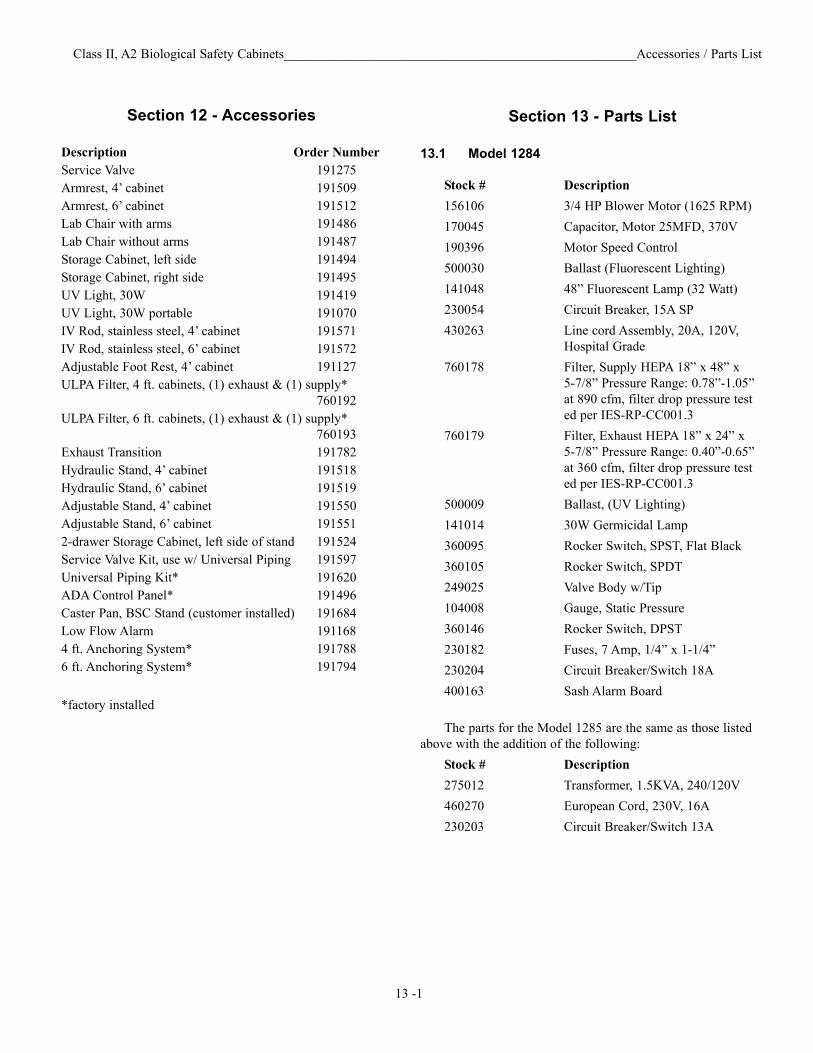
Section 13 - Parts List
13.1 Model 1284
Stock # Description156106 3/4 HP Blower Motor (1625 RPM)170045 Capacitor, Motor 25MFD, 370V190396 Motor Speed Control 500030 Ballast (Fluorescent Lighting)141048 48” Fluorescent Lamp (32 Watt)230054 Circuit Breaker, 15A SP430263 Line cord Assembly, 20A, 120V,
Hospital Grade 760178 Filter, Supply HEPA 18” x 48” x
5-7/8” Pressure Range: 0.78”-1.05” at 890 cfm, filter drop pressure tested per IES-RP-CC001.3
760179 Filter, Exhaust HEPA 18” x 24” x 5-7/8” Pressure Range: 0.40”-0.65” at 360 cfm, filter drop pressure tested per IES-RP-CC001.3
500009 Ballast, (UV Lighting) 141014 30W Germicidal Lamp 360095 Rocker Switch, SPST, Flat Black360105 Rocker Switch, SPDT249025 Valve Body w/Tip 104008 Gauge, Static Pressure 360146 Rocker Switch, DPST230182 Fuses, 7 Amp, 1/4” x 1-1/4”230204 Circuit Breaker/Switch 18A400163 Sash Alarm Board
The parts for the Model 1285 are the same as those listedabove with the addition of the following:
Stock # Description 275012 Transformer, 1.5KVA, 240/120V460270 European Cord, 230V, 16A230203 Circuit Breaker/Switch 13A
Class II, A2 Biological Safety Cabinets_____________________________________________________Accessories / Parts List
Section 12 - Accessories
Description Order NumberService Valve 191275 Armrest, 4’ cabinet 191509 Armrest, 6’ cabinet 191512 Lab Chair with arms 191486 Lab Chair without arms 191487 Storage Cabinet, left side 191494 Storage Cabinet, right side 191495 UV Light, 30W 191419 UV Light, 30W portable 191070 IV Rod, stainless steel, 4’ cabinet 191571 IV Rod, stainless steel, 6’ cabinet 191572 Adjustable Foot Rest, 4’ cabinet 191127 ULPA Filter, 4 ft. cabinets, (1) exhaust & (1) supply*
760192 ULPA Filter, 6 ft. cabinets, (1) exhaust & (1) supply*
760193 Exhaust Transition 191782 Hydraulic Stand, 4’ cabinet 191518 Hydraulic Stand, 6’ cabinet 191519 Adjustable Stand, 4’ cabinet 191550 Adjustable Stand, 6’ cabinet 191551 2-drawer Storage Cabinet, left side of stand 191524 Service Valve Kit, use w/ Universal Piping 191597 Universal Piping Kit* 191620 ADA Control Panel* 191496Caster Pan, BSC Stand (customer installed) 191684Low Flow Alarm 1911684 ft. Anchoring System* 1917886 ft. Anchoring System* 191794
*factory installed
13 -1
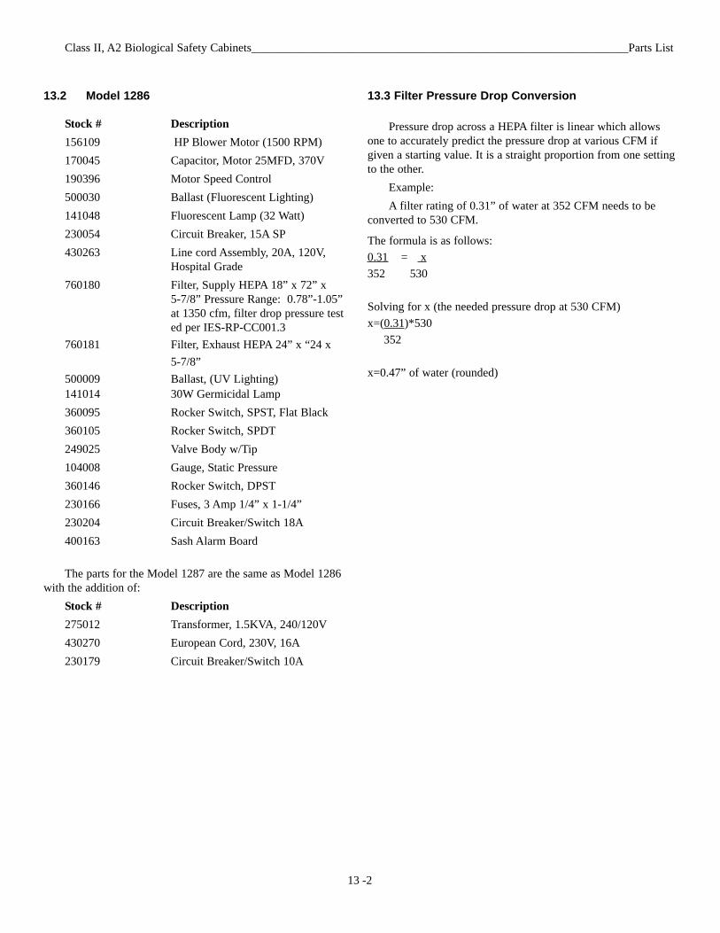
13.2 Model 1286
Stock # Description156109 HP Blower Motor (1500 RPM) 170045 Capacitor, Motor 25MFD, 370V190396 Motor Speed Control 500030 Ballast (Fluorescent Lighting)141048 Fluorescent Lamp (32 Watt) 230054 Circuit Breaker, 15A SP430263 Line cord Assembly, 20A, 120V,
Hospital Grade 760180 Filter, Supply HEPA 18” x 72” x
5-7/8” Pressure Range: 0.78”-1.05” at 1350 cfm, filter drop pressure tested per IES-RP-CC001.3
760181 Filter, Exhaust HEPA 24” x “24 x 5-7/8”
500009 Ballast, (UV Lighting)141014 30W Germicidal Lamp 360095 Rocker Switch, SPST, Flat Black360105 Rocker Switch, SPDT249025 Valve Body w/Tip 104008 Gauge, Static Pressure360146 Rocker Switch, DPST230166 Fuses, 3 Amp 1/4” x 1-1/4” 230204 Circuit Breaker/Switch 18A400163 Sash Alarm Board
The parts for the Model 1287 are the same as Model 1286with the addition of:
Stock # Description 275012 Transformer, 1.5KVA, 240/120V430270 European Cord, 230V, 16A230179 Circuit Breaker/Switch 10A
13.3 Filter Pressure Drop Conversion
Pressure drop across a HEPA filter is linear which allowsone to accurately predict the pressure drop at various CFM ifgiven a starting value. It is a straight proportion from one settingto the other.
Example: A filter rating of 0.31” of water at 352 CFM needs to be
converted to 530 CFM.
The formula is as follows:0.31 = x352 530
Solving for x (the needed pressure drop at 530 CFM) x=(0.31)*530
352
x=0.47” of water (rounded)
13 -2
Class II, A2 Biological Safety Cabinets________________________________________________________________Parts List
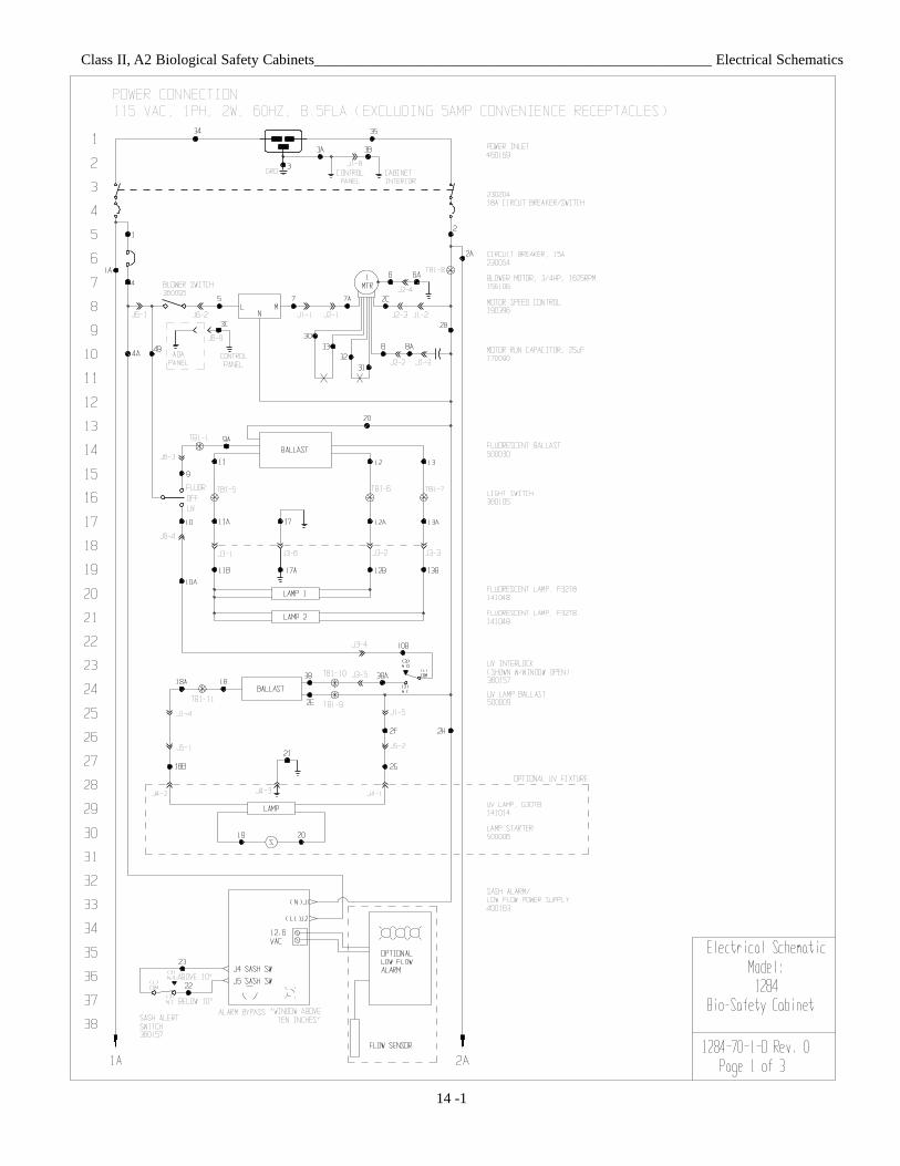
Class II, A2 Biological Safety Cabinets______________________________________________________ Electrical Schematics
14 -1
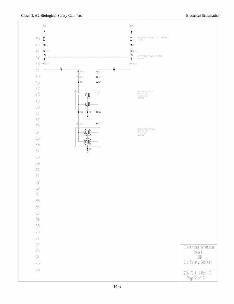
Class II, A2 Biological Safety Cabinets______________________________________________________ Electrical Schematics
14 -2
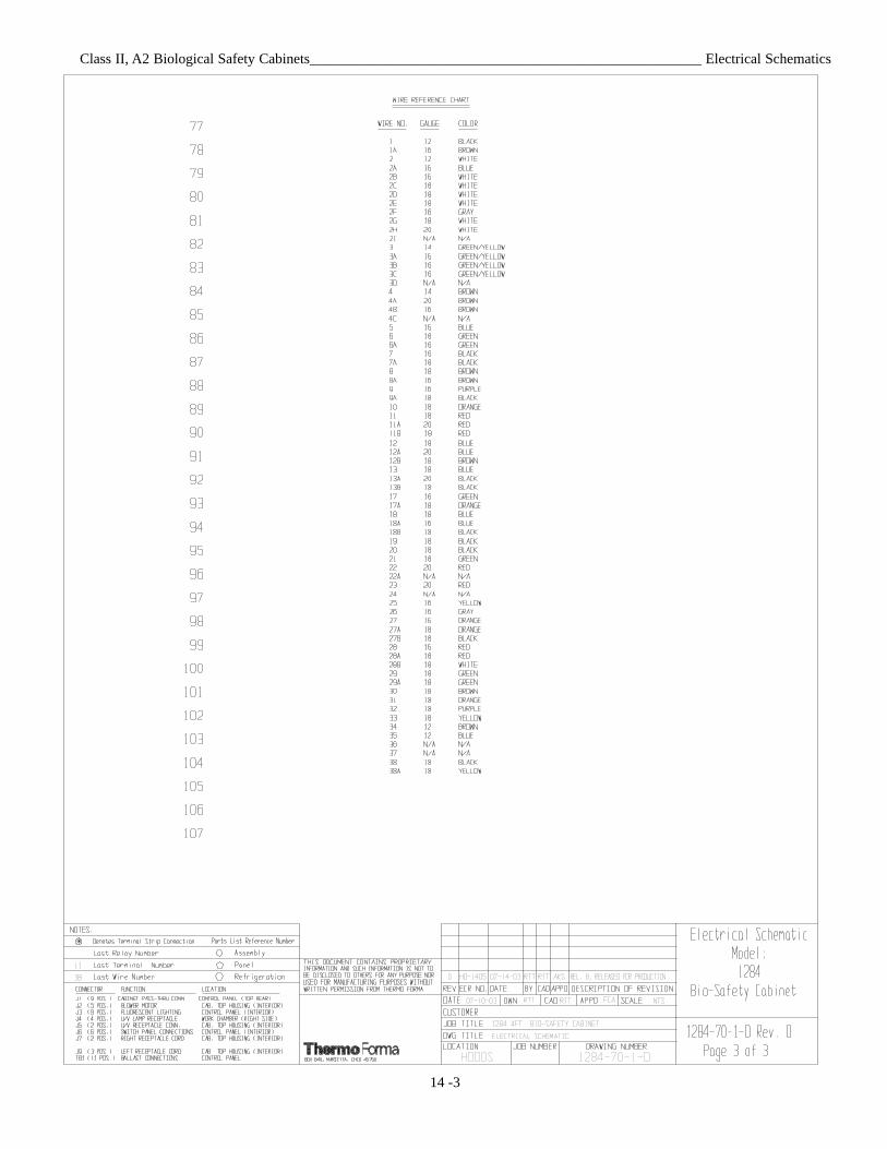
Class II, A2 Biological Safety Cabinets______________________________________________________ Electrical Schematics
14 -3
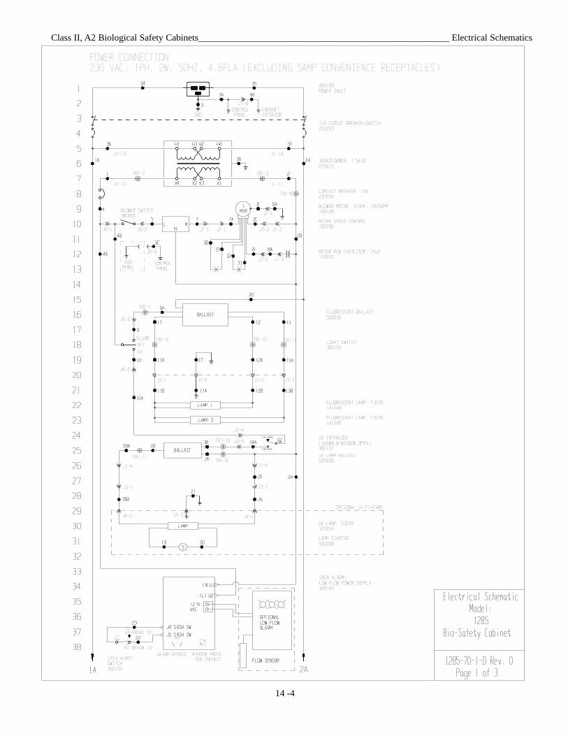
Class II, A2 Biological Safety Cabinets______________________________________________________ Electrical Schematics
14 -4
Class II, A2 Biological Safety Cabinets______________________________________________________ Electrical Schematics
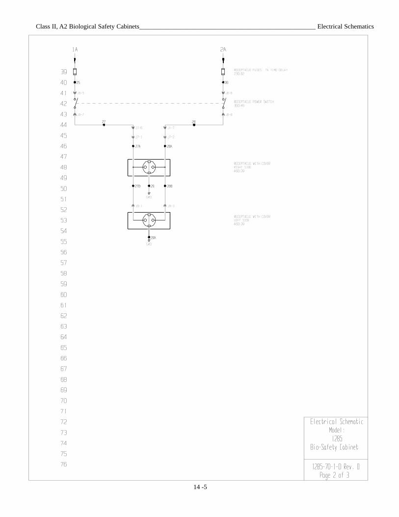
14 -5
Class II, A2 Biological Safety Cabinets______________________________________________________ Electrical Schematics
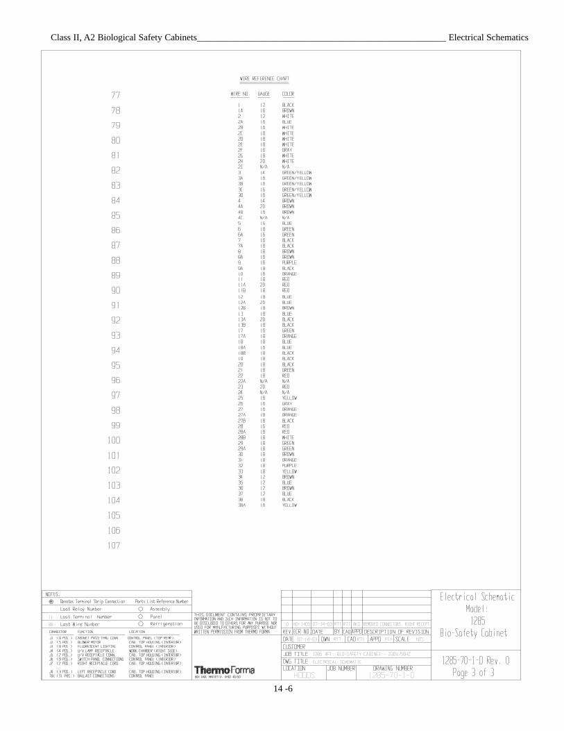
14 -6
Class II, A2 Biological Safety Cabinets______________________________________________________ Electrical Schematics
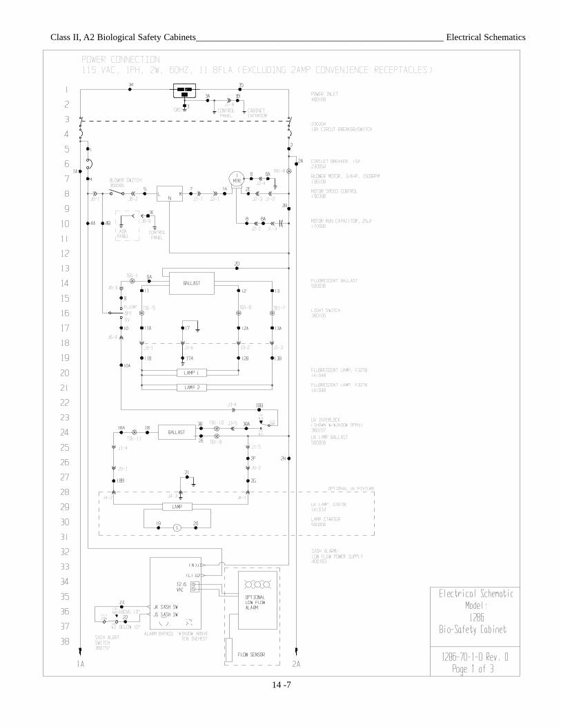
14 -7
Class II, A2 Biological Safety Cabinets______________________________________________________ Electrical Schematics
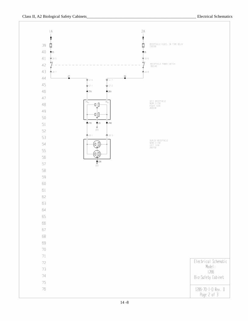
14 -8
Class II, A2 Biological Safety Cabinets______________________________________________________ Electrical Schematics
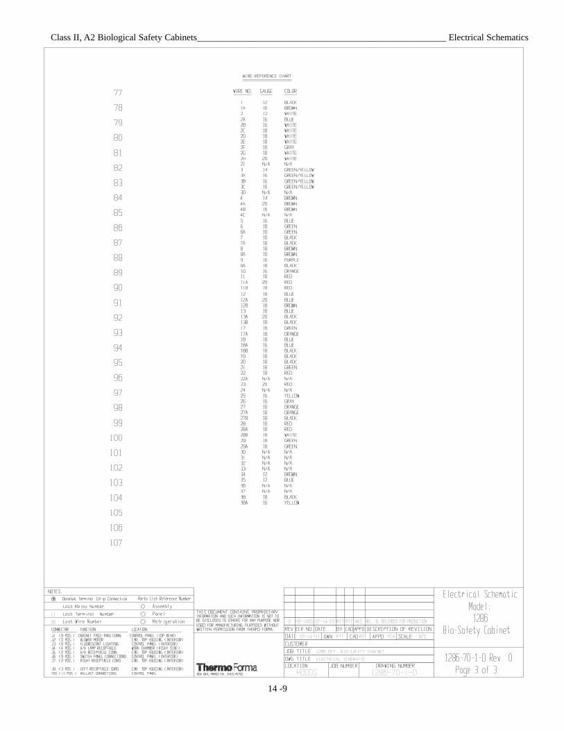
14 -9
Class II, A2 Biological Safety Cabinets______________________________________________________ Electrical Schematics
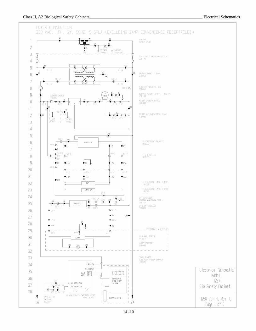
14 -10
Class II, A2 Biological Safety Cabinets______________________________________________________ Electrical Schematics
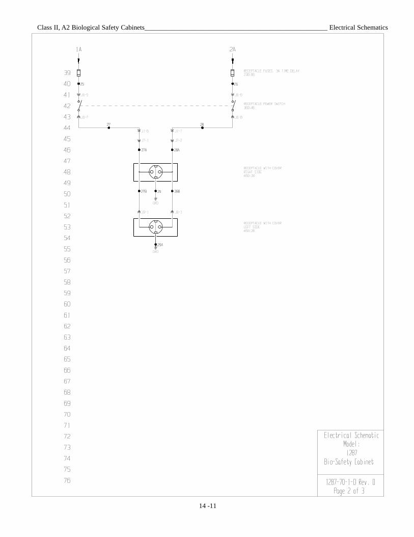
14 -11
Class II, A2 Biological Safety Cabinets______________________________________________________ Electrical Schematics
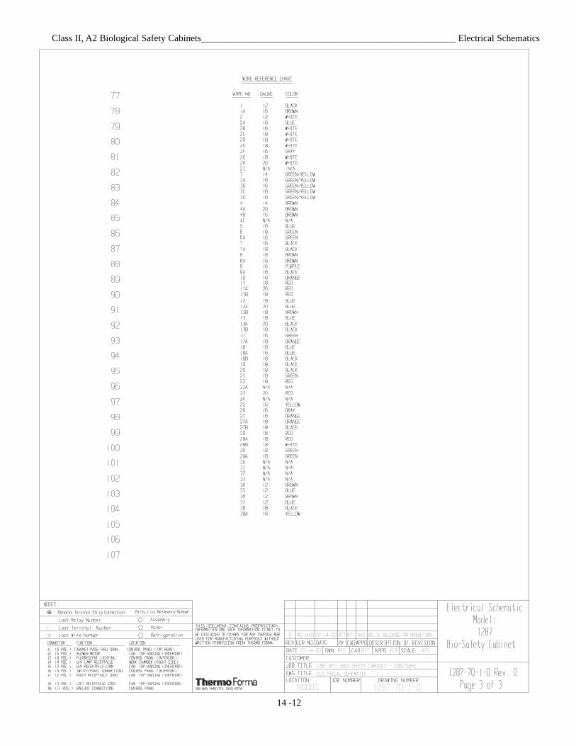
14 -12

THERMO ELECTRON CORPORATION LAMINAR FLOW EQUIPMENT WARRANTY USAThe Warranty Period starts two weeks from the date your equipment is shipped from our facility. This allows shipping time so the war-ranty will go into effect at approximately the same time your equipment is delivered. The warranty protection extends to any subse-quent owner.
During the first thirty-six (36) months, component parts proven to be non-conforming in material or workmanship will be repaired orreplaced at Thermo’s expense, including labor. Installation, calibration and certification is not covered by this warranty agreement. TheTechnical Services Department must be contacted for warranty determination and direction prior to performance of any repairs.Expendable items, glass, filters and gaskets are excluded from this warranty.
Replacement or repair of component parts or equipment under this warranty shall not extend the warranty to either the equipment or tothe component part beyond the original warranty period. The Technical Services Department must give prior approval for return of anycomponent or equipment. At Thermo’s option, all non-conforming parts must be returned to Thermo postage paid and replacementparts are shipped FOB destination.
THIS WARRANTY IS EXCLUSIVE AND IN LIEU OF ALL OTHER WARRANTIES, WHETHER WRITTEN, ORAL, OR IMPLIED. NOWARRANTIES OF MERCHANTABILITY OR FITNESS FOR A PARTICULAR PURPOSE SHALL APPLY. Thermo shall not be liable forany indirect or consequential damages including, without limitation, damages to lost profits or loss of products.
Your local Thermo Sales Office is ready to help with comprehensive site preparation information before your equipment arrives. Printedinstruction manuals carefully detail equipment installation, operation and preventive maintenance.
If equipment service is required, please call your Technical Services Department at 1-888-213-1790 (USA and Canada) or 1-740-373-4763. We’re ready to answer your questions on equipment warranty, operation, maintenance, service, and special applications. Outsidethe USA, contract your local distributor for warranty information.
ISO9001REGISTERED
Rev. 3 4/03

THERMO ELECTRON CORPORATION LAMINAR FLOW EQUIPMENT WARRANTY INTERNATIONAL
The Warranty Period starts two months from the date your equipment is shipped from our facility. This allows shippingtime so the warranty will go into effect at approximately the same time your equipment is delivered. The warranty protec-tion extends to any subsequent owner.
During the first thirty six (36) months, component parts proven to be non-conforming in material or workmanship will berepaired or replaced at Thermo’s expense, excepting labor. Installation, calibration and certification is not covered by thiswarranty agreement. The Technical Services Department must be contacted for warranty determination and directionprior to performance of any repairs. Expendable items, glass, filters and gaskets are excluded from this warranty.
Replacement or repair of component parts or equipment under this warranty shall not extend the warranty to either theequipment or to the component part beyond the original warranty period. The Technical Services Department must giveprior approval for return of any component or equipment. At Thermo’s option, all non-conforming parts must be returnedto Thermo postage paid and replacement parts are shipped FOB destination.
THIS WARRANTY IS EXCLUSIVE AND IN LIEU OF ALL OTHER WARRANTIES, WHETHER WRITTEN, ORAL, ORIMPLIED. NO WARRANTIES OF MERCHANTABILITY OR FITNESS FOR A PARTICULAR PURPOSE SHALL APPLY.Thermo shall not be liable for any indirect or consequential damages including, without limitation, damages to lost profitsor loss of products.
Your local Thermo Sales Office is ready to help with comprehensive site preparation information before your equipmentarrives. Printed instruction manuals carefully detail equipment installation, operation and preventive maintenance.
If equipment service is required, please call your Technical Services Department at 1-888-213-1790 (USA or Canada) or1-740-373-4763. We’re ready to answer your questions on equipment warranty, operation, maintenance, service, andspecial applications. Outside the USA, contract your local distributor for warranty information.
ISO9001REGISTERED
Rev. 3 4/03

Locating a Certification Company Biological safety cabinet certification consists of a series of tests designed to verify that the cabinet is performing within operating parameters established by the manufacturer. To assure that a biological safety cabinet is operating as intended, each cabinet should be field-tested at the time of installation and at least annually thereafter. Cabinets should be re-certified whenever HEPA filters are changed, internal maintenance is performed, or is relocated. Three industry-related organizations maintain lists of companies and individuals who are active in the certification industry. You may contact these organizations at the addresses listed below. NSF International (NSF) and International Air Filtration Certifiers Association (IAFCA) sponsor certifier accreditation programs. Accredited certifiers have demonstrated proficiency at testing biological safety cabinets by successfully completing written and/or practical examinations. Biohazard Cabinet Field Certifier Program NSF International PO Box 130140 789 N. Dixboro Rd Ann Arbor, MI 48113-0140 Telephone (734) 769-8010 Or (800) NSF-MARK Fax (734) 769-0109 http://www.nsf.org/Certified/Biohazard-Certifier
IAFCA PO Box 12155 Columbus, OH 43212 Telephone (888) 679-1904 Fax (614) 486-1108 http://www.iafca.com/certifier.html
The Controlled Environment Testing Association (CETA) is a trade association devoted to promoting and developing quality assurance within the controlled environment testing industry. A list of active members is available by contacting the organization. Controlled Environment Testing Association 1500 Sunday Drive Suite 102 Raleigh, NC 27607 Telephone (919) 787-5181 Fax (919) 787-4916 http://www.cetainternational.org/members/corp_indiv.htm For your convenience we have included a partial list of agencies that perform certification on our website. If you do not find someone listed in your area, please contact Thermo Forma’s technical services department for additional references.
Thermo Electron CorporationControlled Environment Corporation
Millcreek Road, P.O. Box 649Marietta, Ohio 45750
U.S.A.
Telephone (740) 373-4763Telefax (740) 373-4189