modelling localised fracture of reinforced concrete...
TRANSCRIPT
Modelling localised fracture ofreinforced concrete structuresFeiyu Liao PhDResearch Fellow, Department of Mechanical, Aerospace and CivilEngineering, College of Engineering, Design and Physical Sciences,Brunel University, Uxbridge, Middlesex, UK
Zhaohui Huang PhDReader, Department of Mechanical, Aerospace and Civil Engineering,College of Engineering, Design and Physical Sciences, Brunel University,Uxbridge, Middlesex, UK
This paper presents a robust finite-element procedure for simulating the localised fracture of reinforced concrete
members. In this new model, the concrete member is modelled as an assembly of plain concrete, reinforcing steel bar
and bond-link elements. The four-node quadrilateral elements are used for two-dimensional modelling of plain
concrete elements, in which the extended finite-element method is adopted to simulate the formation and growth
of individual cracks. The reinforcing steel bars are modelled using a three-node beam–column element. The two-node
bond-link elements are used for modelling the interaction between plain concrete and reinforcing steel bar elements.
It is evident that the non-linear procedure proposed in this paper can properly model the formation and propagation
of individual localised cracks within the reinforced concrete structures. The model presented in this paper enables the
researchers and designers to access the integrity of reinforced concrete members under extreme loading conditions
using mesh-independent extended finite-element method.
NotationBenra enhanced strain–displacement transformation matrix
Bstau regular strain–displacement transformation matrix
D material constitutive matrix of plain concretef int element internal force vectorf aint enhanced element internal force vector
f uint regular element internal force vector
fΓint element internal force vector corresponding to
tractionGf fracture energy of concreteKaa enhanced element stiffness matrixKuu regular element stiffness matrixKΓ element stiffness matrix corresponding to tractionsign (x) sign functionTa tangent stiffness of traction–separation relationta traction within the cracksucont vector of continuous displacement fieldudis vector of discontinuous displacement fieldΨi (x) enhancement function
1. IntroductionRecently, localised fracture of reinforced concrete membershas been of interest to many researchers and engineers. In thecase of utilisation of reinforced concrete structures in offshorestructures, it is very important to evaluate the effect of individ-ual crack opening on the corrosion of reinforced steel bars,which could cause a significant strength loss of the structural
members. When structures are subjected to extreme loadingconditions such as fire, the reinforced concrete beams or slabsare forced into high deformation, and large individual crackscan be formed within the structural members. This phenom-enon was observed in some previous experimental tests (Baileyand Toh, 2007; Foster, 2006; Foster et al., 2004). Those largeindividual cracks influence the exposure condition of reinfor-cing steel bars to fire and in some cases the steel reinforce-ments are directly exposed to fire which significantly reducesthe fire resistance of the structures. In the case of the fibre-reinforced plastic (FRP) strength reinforced concrete beam, thelocalised concrete cracking could cause possible debondingfailure of externally strengthening FRP layer (Chen et al.,2011). In addition to the global responses like ultimatestrength and deflection the propagation of localised cracks inthe concrete surrounding the reinforcing steel also affects thebond–slip behaviour between the steel bar and concrete(Cervenka et al., 2003; Gao et al., 2013; Rots, 1985). In thepast, plenty of researches have been devoted to develop thenumerical models for modelling of the reinforced concretestructure based on a continuum approach in which smearedcracking was adopted to simulate cracks (Huang et al., 2003;Suidan and Schnobrich, 1973; Vecchio and DeRoo, 1995).However, the smeared cracking model is not capable of captur-ing the formations and propagations of individual crackswithin a reinforced concrete member. At present, very littleresearch has been done on the modelling of localised fracturesfor reinforced concrete structural members.
53
Engineering and Computational MechanicsVolume 169 Issue EM2
Modelling localised fracture of reinforcedconcrete structuresLiao and Huang
Proceedings of the Institution of Civil EngineersEngineering and Computational Mechanics 169 June 2016 Issue EM2Pages 53–69 http://dx.doi.org/10.1680/jencm.15.00008Paper 1500008Received 02/03/2015 Accepted 12/08/2015Published online 10/09/2015Keywords: computational mechanics/concrete structures/stressanalysis
Published with permission by the ICE under the CC-BY licencehttp://creativecommons.org/licenses/by/4.0/
Downloaded by [ Brunel University] on [30/06/16]. Copyright © ICE Publishing, all rights reserved.
In the past, a discrete-cracking model has been used success-fully for modelling cracks in structural members when thecrack path was known in advance. In these cases, the finite-element (FE) mesh was constructed in such a way that thecrack path coincided with the element boundaries. However,this approach has to limit cracks to interelement boundaries,or requires performing remeshing during the analysis processin order to capture crack propagation. To overcome thisproblem, extended FE method (XFEM) was developed andintroduced (Belytschko and Black, 1999; Möes et al., 1999)based on the partition of unity theory (Mellenk and Babuska,1996). Recently, a number of XFEM approaches in conjunc-tion with cohesive-zone models have been developed to analyselocalisation and fracture in engineering materials (Möesand Belytschko, 2002; Verhoose et al., 2009; Wells and Sluys,2001; Zi and Belytschko, 2003). In the last decade, XFEMapproach has been successfully extended to many applicationsin modelling two-dimensional (2D) and three-dimensional(3D) problems (Duan et al., 2009; Gravouil et al., 2002;Hansbo and Hansbo, 2004; Möes et al., 2002; Sukumar et al.,2000). However, so far the application of XFEM for modellingof reinforced concrete members is still very limited.
The main objective of this paper is to present a robust FE pro-cedure for modelling the localised fracture of reinforced con-crete members. The four-node quadrilateral elements are usedfor modelling of plain concrete part of reinforced concretemembers, in which the XFEM is adopted to simulate the for-mation and growth of cracks. The reinforcing steel bars aremodelled by using the three-node beam–column elements andtwo-node bond-link elements are employed for modelling theinteraction between plain concrete and reinforcing steel barelements. If XFEM is applied to the plain concrete element itsnodal displacement will be divided into two parts, continuouspart and discontinuous part, both of them cannot be coinci-dent with the nodal displacement of steel bars. To resolve thisproblem, a shifted enhancement function proposed by Zi andBelytschko (2003) is adopted so that the total nodal displace-ment of the plain concrete element can be obtained in the pro-cedure rather than only the continuous part. In this way, thenodal displacement of concrete and reinforcing steel bar cancoincide with each other in the proposed model. In this paper,the influence of bond characteristics between the concreteand reinforcing steel bar on the localised crack initiation andpropagation within a reinforced concrete member is alsoexamined.
2. Non-linear procedure
2.1 Reinforcing steel bar and bond-link elementsAs shown in Figure 1, a reinforced concrete beam is modelledas an assembly of finite plain concrete, reinforcing steel barand bond-link elements. In the present model, a general 3D
isoparametric three-node beam–column element developed byHuang et al. (2009) is adopted to represent the main reinfor-cing steel bars of reinforced concrete members. The materialnon-linearities of concrete and steel follows the models speci-fied in Eurocode 2 (BSI, 2004).
To model the interaction between the reinforcing steel andconcrete within the reinforced concrete structural members, atwo-node bond-link element with zero length developed pre-viously by Huang (2010) was used. As shown in Figure 1(b),the bond-link elements are used to link four-node quadrilateralplain concrete elements with three-node reinforcing steel barelements. The bond-link element is a specialised two-nodeelement of zero length, which has three translational degreesof freedom u, v, w and three rotational degrees of freedom θx,θy, θz at each node, where x, y, z are local coordinates of thereinforcing steel element in which x is the direction of thelongitudinal axis of the reinforcing steel bar (Figure 1(c)). It isassumed that the slip between the reinforcing steel and con-crete is only related to the longitudinal axis direction(x-direction).
For reinforcing steel bars, apart from the relative slip along thelongitudinal axis direction (x-direction) between the concreteand steel bars the concrete prevents relative movement of rein-forcing bars in other directions. It is, therefore, reasonable toassume that common nodes of the concrete and reinforcingbar elements have identical rotations and movements in y andz directions. Hence, in this bond-link element the stiffness coef-ficients of the element stiffness matrix k2, k3, k4, k5, k6, whichare related to the degrees of freedom for v, w and θx, θy, θz,respectively, are assumed to have infinite magnitude (1015).The stiffness coefficient k1, which is related to the degree offreedom for u, can be calculated using an empirical bondstress–slip relationship given in the CEB-FIP Model Code(CEB-FIP, 1993).
The bond-link element is capable of modelling perfect, partialand zero bond between the concrete and reinforcing steel barwithin the reinforced concrete structures. For partial bond con-dition (ribbed steel bar and smooth steel bar), the averagebond stress (τb) and stiffness coefficient k1 of the bond elementare calculated using the bond stress–slip curves proposed inthe CEB-FIP Model Code (CEB-FIP, 1993). For perfectbond condition k1=1015(N/mm) and no failure of the bondare assumed. For the zero bond condition, it is assumed thatthere is no interaction between the concrete and reinforcingsteel bars (k1=0, τb=0). The details of the bond-link elementcan be found in Huang (2010).
As shown in Figure 1(b), the quadrilateral plain concreteelements and the steel bar elements are connected to eachother using two-node bond-link elements. The displacement
54
Engineering and Computational MechanicsVolume 169 Issue EM2
Modelling localised fracture of reinforcedconcrete structuresLiao and Huang
Downloaded by [ Brunel University] on [30/06/16]. Copyright © ICE Publishing, all rights reserved.
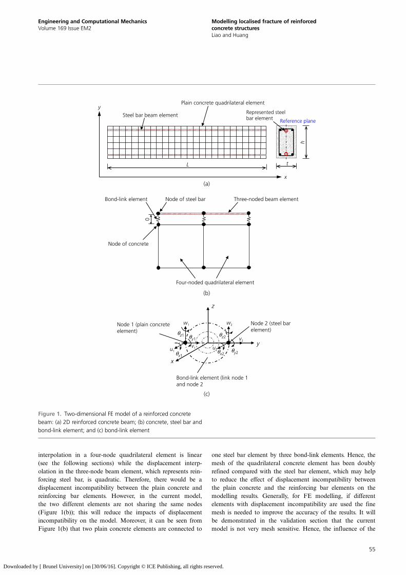
interpolation in a four-node quadrilateral element is linear(see the following sections) while the displacement interp-olation in the three-node beam element, which represents rein-forcing steel bar, is quadratic. Therefore, there would be adisplacement incompatibility between the plain concrete andreinforcing bar elements. However, in the current model,the two different elements are not sharing the same nodes(Figure 1(b)); this will reduce the impacts of displacementincompatibility on the model. Moreover, it can be seen fromFigure 1(b) that two plain concrete elements are connected to
one steel bar element by three bond-link elements. Hence, themesh of the quadrilateral concrete element has been doublyrefined compared with the steel bar element, which may helpto reduce the effect of displacement incompatibility betweenthe plain concrete and the reinforcing bar elements on themodelling results. Generally, for FE modelling, if differentelements with displacement incompatibility are used the finemesh is needed to improve the accuracy of the results. It willbe demonstrated in the validation section that the currentmodel is not very mesh sensitive. Hence, the influence of the
(a)
(b)
(c)
x
y
L t
h
Plain concrete quadrilateral element
Steel bar beam element Reference plane
Represented steel bar element
Node of concrete
0
Node of steel barBond-link element
Four-noded quadrilateral element
Three-noded beam element
Node 1 (plain concreteelement)
Node 2 (steel barelement)
x
y
z
u1
v1
w1
θy1θz1 θz2
θy2θx2u2
v2
w2
Bond-link element (link node 1and node 2
θx1
Figure 1. Two-dimensional FE model of a reinforced concretebeam: (a) 2D reinforced concrete beam; (b) concrete, steel bar andbond-link element; and (c) bond-link element
55
Engineering and Computational MechanicsVolume 169 Issue EM2
Modelling localised fracture of reinforcedconcrete structuresLiao and Huang
Downloaded by [ Brunel University] on [30/06/16]. Copyright © ICE Publishing, all rights reserved.
displacement incompatibility of two different elements on thecurrent model is limited.
To transform the 3D problem into a 2D model, all reinforcingsteel bars at the same height within the cross-section of thebeam are represented by an equivalent steel bar element at thereference plane, as shown in Figure 1(a). The cross-sectionalarea of the equivalent steel bar element equals the total cross-sectional area of all real steel bars represented. Besides, thecontact area of the equivalent steel bar element with concreteis the summation of the total contact areas of all the real steelbars represented.
2.2 Plain concrete element
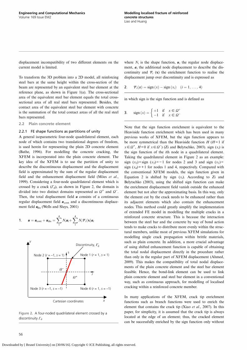
2.2.1 FE shape functions as partitions of unityA general isoparametric four-node quadrilateral element, eachnode of which contains two translational degrees of freedom,is used herein for representing the plain 2D concrete element(Bathe, 1996). For modelling the concrete cracking, theXFEM is incorporated into the plain concrete element. Thekey idea of the XFEM is to use the partition of unity todescribe the discontinuous displacement and the displacementfield is approximated by the sum of the regular displacementfield and the enhancement displacement field (Möes et al.,1999). Considering a four-node quadrilateral element which iscrossed by a crack (Γd), as shown in Figure 2, the domain isdivided into two distinct domains represented as Ω+ and Ω−.Then, the total displacement field u consists of a continuousregular displacement field ucont and a discontinuous displace-ment field udis (Wells and Sluys, 2001)
1: u ¼ ucont þ udis ¼X41
NiuiþX41
NiΨ iðxÞai
where Ni is the shape function, u i the regular node displace-ment, a i the additional node displacement to describe the dis-continuity and Ψi (x) the enrichment function to realise thedisplacement jump over discontinuity and is expressed as
2: Ψ iðxÞ ¼ sign ðxÞ sign ðxiÞ ði ¼ 1; . . . ; 4Þ
in which sign is the sign function and is defined as
3: sign ðxÞ ¼ þ1 if x [ Ωþ
1 if x [ Ω
Note that the sign function enrichment is equivalent to theHeaviside function enrichment which has been used in manyprevious works of XFEM, but the sign function appears tobe more symmetrical than the Heaviside function H (H=1 ifx[Ω+, H=0 if x[Ω−) (Zi and Belytschko, 2003). sign (xi) isthe sign function of the ith node in a quadrilateral element.Taking the quadrilateral element in Figure 2 as an example:sign (x2)=sign (x3)=−1 for nodes 2 and 3 and sign (x1)=sign (x4)=+1 for nodes 1 and 4, respectively. Compared withthe conventional XFEM models, the sign function given inEquation 2 is shifted by sign (xi). According to Zi andBelytschko (2003), using the shifted sign function can makethe enrichment displacement field vanish outside the enhancedelement but not alter the approximating basis. In this way, onlythe element cut by the crack needs to be enhanced rather thanits adjacent elements which also contain the enhancementnodes. This method could greatly simplify the implementationof extended FE model in modelling the multiple cracks in areinforced concrete structure. This is because the interactionbetween the steel bar and the concrete by way of bond actiontends to make cracks to distribute more evenly within the struc-tural members, unlike most of previous XFEM simulations formodelling single crack propagation within brittle materials,such as plain concrete. In addition, a more crucial advantageof using shifted enhancement function is capable of obtainingthe total nodal displacement directly in the procedure ratherthan only in the regular part of XFEM displacement (Ahmed,2009). This makes the compatibility of total nodal displace-ments of the plain concrete element and the steel bar elementfeasible. Hence, the bond-link element can be used to linkplain concrete element and steel bar element in a conventionalway, such as continuous approach, for modelling of localisedcracking within a reinforced concrete member.
In many applications of the XFEM, crack tip enrichmentfunctions such as branch functions were used to enrich theelement that contains the crack tip (Xiao et al., 2007). In thispaper, for simplicity, it is assumed that the crack tip is alwayslocated at the edge of an element; thus, the cracked elementcan be successfully enriched by the sign function only without
Ω –
Ω +
Discontinuity, Γd
x
y
Cartesian coordinates
r
sNode 1 (r = 1, s = 1)
Node 4 (r = 1, s = –1)
Node 2 (r = –1, s = 1)
Node 3 (r = –1, s = –1)
Figure 2. A four-noded quadrilateral element crossed by adiscontinuity Γd
56
Engineering and Computational MechanicsVolume 169 Issue EM2
Modelling localised fracture of reinforcedconcrete structuresLiao and Huang
Downloaded by [ Brunel University] on [30/06/16]. Copyright © ICE Publishing, all rights reserved.
other enrichment functions. Thus, the crack branching is notincluded in the proposed model. It is assumed that a particularelement contains only one crack. The main purpose of themodel developed in this paper is to capture the major localisedcracks within the concrete beam. Therefore, in order toenhance the computational efficiency of the proposed model,precise modelling of the crack tip and crack branching is notconsidered in this paper. It will be demonstrated in the vali-dation section that the current model is not very meshsensitive.
2.2.2 Element stiffness matrix, KIn the case of 2D four-node quadrilateral element as shown inFigure 2, the element nodal displacement vector û can be rep-resented as
4: u ¼ uiai
¼ u1 v1 u2 v2 u3 v3 u4 v4 a1 b1 a2 b2 a3 b3 a4 b4½ T
where ui and νi are the regular nodal displacements related tox and y coordinates, respectively, and ai and bi are enhance-ment nodal displacements related to x and y coordinates,respectively.
The total strain within the element in which the enhancementdegrees of freedom are included can be expressed as
5: ε ¼ εcont þ εdis ¼εxεyγxy
8<:
9=; ¼ Bu ¼ Bu
sta Baenr
uiai
in which εcont is the continuous strain and εdis the discontinu-ous strain; B sta
u the standard strain–displacement transform-ation matrix corresponding to the regular degrees of freedomui and B enr
a the enrichment strain–displacement transformation
matrix corresponding to the additional enhancement degreesof freedom ai.
The shape functions of a general quadrilateral element are cal-culated as (Bathe, 1996)
6:
N1 ¼ 14ð1þ rÞð1þ sÞ
N2 ¼ 14ð1 rÞð1þ sÞ
N3 ¼ 14ð1 rÞð1 sÞ
N4 ¼ 14ð1þ rÞð1 sÞ
Hence, the strain–displacement transformation matrix Bincluding the regular part and the enhancement part can beobtained as B=[B sta
u B enra ], in which
where Ψi(x) (i=1−4) is the enrichment function given inEquation 2, and the matrix L contains the differential oper-ators. If strains are reasonably small the stresses σ can bewritten as
9: σ ¼σx
σy
τxy
8><>:
9>=>; ¼ Dε ¼ DðεcontþεdisÞ
¼ D Bustaui þ Ψ iðxÞBu
staai
in which D is the constitutive matrix of concrete.
In a FE model, the equilibrium conditions between theinternal and the external ‘force’ has to be satisfied. To formthe element stiffness matrix and internal force vector, the
7:
Busta ¼ LN
¼ LN1 0 N2 0 N3 0 N4 0
0 N1 0 N2 0 N3 0 N4
" #
¼Bsta1x 0 Bsta2x 0 Bsta3x 0 Bsta4x 0
0 Bsta1y 0 Bsta2y 0 Bsta3y 0 Bsta4y
Bsta1y Bsta1x Bsta2y Bsta2x Bsta3y Bsta3x Bsta4y Bsta4x
2664
3775
8:
Baenr ¼ Ψ iðxÞLN
¼ L ¼ LΨ 1ðxÞN1 0 Ψ 2ðxÞN2 0 Ψ 3ðxÞN3 0 Ψ 4ðxÞN4 0
0 Ψ 1ðxÞN1 0 Ψ 2ðxÞN2 0 Ψ 3ðxÞN3 0 Ψ 4ðxÞN4
¼Benr1x 0 Benr2x 0 Benr3x 0 Benr4x 0
0 Benr1y 0 Benr2y 0 Benr3y 0 Benr4y
Benr1y Benr1x Benr2y Benr2x Benr3y Benr3x Benr4y Benr4x
264
375
57
Engineering and Computational MechanicsVolume 169 Issue EM2
Modelling localised fracture of reinforcedconcrete structuresLiao and Huang
Downloaded by [ Brunel University] on [30/06/16]. Copyright © ICE Publishing, all rights reserved.
virtual work equation without body forces reads
10: f int ¼ðΩBTσ dΩ ¼ f ext
where f int is the internal force vector and f ext is the externalforce vector. As shown in Figure 2, for the element with crackEquation 10 can be written as
11: f int ¼ðΩBuTstaσ dΩþ
ðΩþ;Ω
BaTenrσ dΩþ
ðΓd
NTtadΓd ¼f ext
The internal force f int contains the regular part f uint, enhance-
ment part f aint and the traction part fΓ
int in which the regular
internal force f uint balances the external force f ext and the
enhancement part f aint is related to traction of crack fΓ
int only,that is
12: f intu ¼ðΩBuTstaσ dΩ ¼ f ext
13: f inta þ f intΓ ¼ðΩþ;Ω
BaTenrσ dΩþ
ðΓd
NTta dΓd ¼ 0
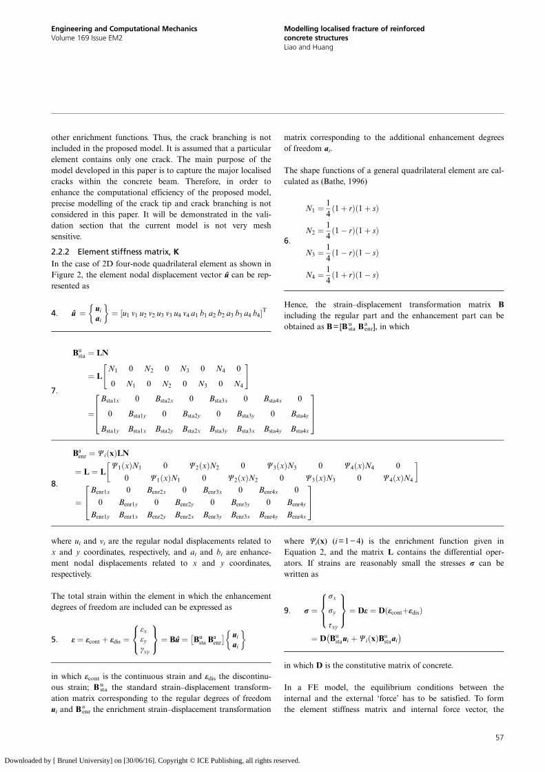
where ta is the traction acting on the discontinuity Γd(Figure 3) and can be written as
14: ta ¼tantas
¼ Taw ¼ Tan 0
0 0
wn
ws
where tan and tas are the traction normal and tangential to acrack, respectively; wn (¼ n ðuþ uÞ ¼ n 2P4
1 Niai) is thecrack opening of the normal direction n of the discontinuity(Γd), and ws is the slide of two crack faces tangential to the dis-continuity (Γd), respectively and Tan is the tangent stiffness ofthe traction-separation law. Using the principle of virtual workon Equations 12 and 13, the element stiffness matrix in termsof incremental displacements can be obtained
Equation 15 can be rewritten as
16: Kdu¼ Kuu Kua
Kau ðKaa þ KΓ Þ
du
da
¼ f ext
0
( ) f intu
f inta þ f intΓ
( )
where Kuu is the element stiffness matrix with reference to theregular degrees of freedom; Kaa is the element stiffness matrixwith reference to the enhancement degrees of freedom; Kua=KauT is related to both; and KΓ is the element stiffness matrix of
traction
17:Kuu ¼
ðΩBuTstaDBu
sta dΩ
¼tðð
ABuTstaDBu
stadxdy
18:
Kua ¼ðΩþ;Ω
BuTstaDBa
enr dΩ
¼tðð
Aþ;ABuTstaDBa
enrdxdy
19:
Kau ¼ðΩþ;Ω
BaTenrDBu
sta dΩ
¼tðð
Aþ;ABaTenrDBu
stadxdy
n
Integration point over the discontinuity
s
x
y
w (Crack opening)
ta (Traction)
Figure 3. Traction of a crack
15:
ÐΩ BuT
staDBusta dΩ
ÐΩþ;Ω BuT
staDBaenr dΩÐ
Ωþ;Ω BaTenrDBu
sta dΩÐΩþ;Ω BaT
enrDBaenr d Ωþ Ð
ΓdN
TTaN dΓd
264
375 du
da
¼ f ext
0
( )
f intu
f inta þ f intΓ
( )
58
Engineering and Computational MechanicsVolume 169 Issue EM2
Modelling localised fracture of reinforcedconcrete structuresLiao and Huang
Downloaded by [ Brunel University] on [30/06/16]. Copyright © ICE Publishing, all rights reserved.
20:
Kaa ¼ðΩþ;Ω
BaTenrDBa
enr dΩ
¼tðð
Aþ;ABaTenrDBa
enrdxdy
21:
KΓ ¼ðΓd
NTTaNdΓd
¼tðΓd
NTOTTdON dΓd
where t is the thickness of the element, N ¼ Nþ N ¼ 2ðNÞand N is the shape function matrix which is defined inEquations 6 and 7. The orthogonal transformation matrix Operforms the transformation of the local orientation of thediscontinuity to the global coordinate system, as shown inFigure 3
22: O ¼cosðx; nÞ cosðx; sÞcosðy; nÞ cosðy; sÞ
" #
where cos(x, n) is the cosine of the angle between the x-axisand the normal orientation of discontinuity, cos(x, s) is thecosine of the angle between the x-axis and the tangential orien-tation of discontinuity.
2.2.3 Element internal force vector, f int
Using the principle of virtual work, the internal force vectorsin Equation 16 can be written as
23:
f intu ¼ðΩBuTstaσ dΩ
¼tðð
ABuTsta σ dxdy
¼tðð
ABuTsta σ det J drds
24:
f inta ¼ðΩþ;Ω
BaTenrσ dΩ
¼tðð
Aþ;ABaTenr σ dxdy
¼tðð
Aþ;ABaTenr σ det J drds
25:
f intΓ ¼tðΓd
NTtadΓd
¼tðΓd
NTOTtddΓd
¼2tðΓd
NTOTtddΓd
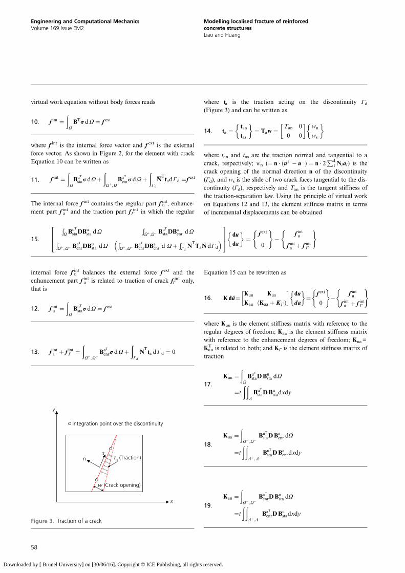
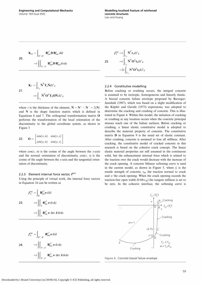
2.2.4 Constitutive modellingBefore cracking or crushing occurs, the integral concreteis assumed to be isotropic, homogeneous and linearly elastic.A biaxial concrete failure envelope proposed by Barzegar-Jamshidi (1987), which was based on a slight modification ofthe Küpfer and Gerstle (1973) expressions, was adopted todetermine the cracking and crushing of concrete. This is illus-trated in Figure 4. Within this model, the initiation of crackingor crushing at any location occurs when the concrete principalstresses reach one of the failure surfaces. Before cracking orcrushing, a linear elastic constitutive model is adopted todescribe the material property of concrete. The constitutivematrix D in Equation 9 is the usual set of elastic constant.After crushing, concrete is assumed to lose all stiffness. Aftercracking, the constitutive model of cracked concrete in thisresearch is based on the cohesive crack concept. The linearelastic material properties are still assumed in the continuoussolid, but the enhancement internal force which is related tothe traction over the crack would decrease with the increase ofthe crack opening. A concrete bilinear softening curve is usedin the current model, as shown in Figure 5, where ft is thetensile strength of concrete, tdn the traction normal to crackand w the crack opening. When the crack opening exceeds thetraction-free open width (0·68wch) the tangent stiffness is set tobe zero. In the cohesive interface, the softening curve is
–0·75
Crushing
Cracking
Cracking
Crushing
A
B
C
D
E
O
–1·0
α = 1
fc1 ≥ fc2
α = fc1/fc2
fc1 / |fc' |
fc2 / |fc' |
+
+–
–
Figure 4. Concrete biaxial failure envelope
59
Engineering and Computational MechanicsVolume 169 Issue EM2
Modelling localised fracture of reinforcedconcrete structuresLiao and Huang
Downloaded by [ Brunel University] on [30/06/16]. Copyright © ICE Publishing, all rights reserved.
governed by the fracture energy, and the fracture energy for-mulation proposed by Bazant and Becq-Giraudon (2002) isadopted in this research.
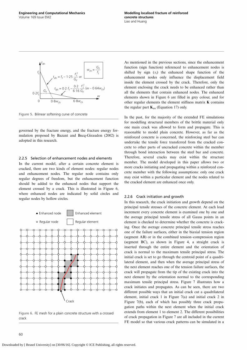
2.2.5 Selection of enhancement nodes and elementsIn the current model, after a certain concrete element iscracked, there are two kinds of element nodes: regular nodesand enhancement nodes. The regular node contains onlyregular degrees of freedom, but the enhancement functionshould be added to the enhanced nodes that support theelement crossed by a crack. This is illustrated in Figure 6,where enhanced nodes are indicated by solid circles andregular nodes by hollow circles.
As mentioned in the previous sections, since the enhancementfunction (sign function) referenced to enhancement nodes isshifted by sign (xi) the enhanced shape function of theenhancement nodes only influence the displacement fieldinside the element crossed by the crack. Therefore, only theelement enclosing the crack needs to be enhanced rather thanall the elements that contain enhanced nodes. The enhancedelements shown in Figure 6 are filled in grey colour, and forother regular elements the element stiffness matrix K containsthe regular part Kuu (Equation 17) only.
In the past, for the majority of the extended FE simulationsfor modelling structural members of the brittle material onlyone main crack was allowed to form and propagate. This isreasonable to model plain concrete. However, as far as thereinforced concrete is concerned, the reinforcing steel bar canundertake the tensile force transferred from the cracked con-crete to other parts of uncracked concrete within the memberthrough bond interaction between the steel bar and concrete.Therefore, several cracks may exist within the structuremember. The model developed in this paper allows two ormore cracks initiating and propagating within a reinforced con-crete member with the following assumptions: only one crackmay exist within a particular element and the nodes related tothe cracked element are enhanced once only.
2.2.6 Crack initiation and growthIn this research, the crack initiation and growth depend on theprincipal tensile stresses of the concrete element. At each loadincrement every concrete element is examined one by one andthe average principal tensile stress of all Gauss points in anelement is checked to determine whether the concrete is crack-ing. Once the average concrete principal tensile stress reachesone of the failure surfaces, either in the biaxial tension region(segment AB) or in the combined tension–compression region(segment BC), as shown in Figure 4, a straight crack isinserted through the entire element and the orientation ofcrack is normal to the maximum tensile principal stress. Theinitial crack is set to go through the centroid point of a quadri-lateral element, and then when the average principal stress ofthe next element reaches one of the tension failure surfaces, thecrack will propagate from the tip of the existing crack into thenext element by the orientation normal to the correspondingmaximum tensile principal stress. Figure 7 illustrates how acrack initiates and propagates. As can be seen, there are twodifferent possible ways that an initial crack cut a quadrilateralelement, initial crack 1 in Figure 7(a) and initial crack 2 inFigure 7(b), each of which has possibly three crack propa-gation paths within the next element when the initial crackextends from element 1 to element 2. The different possibilitiesof crack propagation in Figure 7 are all included in the currentFE model so that various crack patterns can be simulated in a
w
6·8wch0·8wch0
0·2ft
ft
GFw
Gf
tdn
tdn = ft – 1·25f t
2
Gf
ftwch =
(w – 0·64wch)GF
tdn = 0·2 ft –0·2
6·16f t
2
Figure 5. Bilinear softening curve of concrete
Enhanced node
Regular node
Enhanced element
Regular element
Crack
Figure 6. FE mesh for a plain concrete structure with a crossedcrack
60
Engineering and Computational MechanicsVolume 169 Issue EM2
Modelling localised fracture of reinforcedconcrete structuresLiao and Huang
Downloaded by [ Brunel University] on [30/06/16]. Copyright © ICE Publishing, all rights reserved.
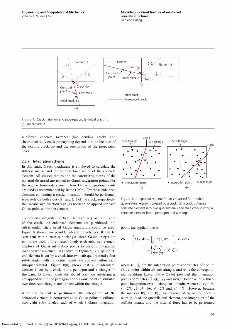
reinforced concrete member (like bending cracks andshear cracks). A crack propagating depends on the location ofthe existing crack tip and the orientation of the propagatedcrack.
2.2.7 Integration schemeIn this study, Gauss quadrature is employed to calculate thestiffness matrix and the internal force vector of the concreteelement. All stresses, strains and the constitutive matrix of thematerial discussed are related to Gauss integration points. Forthe regular four-node element, four Gauss integration pointsare used as recommended by Bathe (1996). For those enhancedelements containing a crack, integration should be performedseparately on both sides (Ω+ and Ω−) of the crack, respectively,that means sign function sign (x) needs to be applied for eachGauss point within the element.
To properly integrate the field (Ω+ and Ω−) on both sidesof the crack, the enhanced elements are partitioned intosub-triangles where usual Gauss quadrature could be used.Figure 8 shows two possible integration schemes. It can beseen that within each sub-triangle, three Gauss integrationpoints are used, and correspondingly each enhanced elementemploys 24 Gauss integration points to perform integrationover the whole element. As shown in Figure 8(a), a quadrilat-eral element is cut by a crack into two sub-quadrilaterals; foursub-triangles with 12 Gauss points are applied within eachsub-quadrilateral. Figure 8(b) shows that a quadrilateralelement is cut by a crack into a pentagon and a triangle. Inthis case, 15 Gauss points distributed over five sub-trianglesare applied within the pentagon and 9 Gauss points distributedover three sub-triangles are applied within the triangle.
After the element is partitioned, the integration of theenhanced element is performed at 24 Gauss points distributedover eight sub-triangles, each of which 3 Gauss integration
points are applied, that is
26:ðFðxÞ dx ¼
ðΩþ
FðxÞ dxþðΩ
FðxÞ dx
¼ 12
X8j¼1
X3i¼1
Fðrji ; sjiÞwj
where (rij, si
j) are the integration point coordinates of the ithGauss point within jth sub-triangle, and wj is the correspond-ing weighting factor. Bathe (1996) provided the integrationpoint coordinates (r′i, s′i)i=1,2,3 and weight factor w′ of a three-point integration over a triangular domain, where r′1= r′3=1/6,r′2=2/3, s′1= s′2=1/6, s′3=2/3 and w′=1/3. However, becausethe matrices Bsta
u and Benra are represented by natural coordi-
nates (r, s) of the quadrilateral element, the integration of thestiffness matrix and the internal force has to be performed
Centroidpoint Element 1
Element 2
1–2
1–1
1–3
Initial crack 1
Crack tip
Element 1Element 2
2–1
2–2
2–3
Centroidpoint Initial crack 2
Crack tip
Initial crackPropagated crack
(a)
(b)
Figure 7. Crack initiation and propagation. (a) Initial crack 1;(b) Initial crack 2
Integration point
Ω – Ω +
Sub-triangle Sub-triangleCrack
Integration point
Ω –
Sub-triangle
Sub-triangle
Crack
Ω +
(a) (b)
Figure 8. Integration scheme for an enhanced four-nodedquadrilateral element crossed by a crack: (a) a crack cutting aconcrete element into two quadrilaterals and (b) a crack cutting aconcrete element into a pentagon and a triangle
61
Engineering and Computational MechanicsVolume 169 Issue EM2
Modelling localised fracture of reinforcedconcrete structuresLiao and Huang
Downloaded by [ Brunel University] on [30/06/16]. Copyright © ICE Publishing, all rights reserved.
with reference to the natural coordinate system of the quadri-lateral element. Therefore, a coordinate transformation shouldbe conducted for changing (r′i, s′i ) to (ri
j, s ij )
27: rji ¼ N tri-1i rsub;j1 þN tri-2
i rsub;j2 þN tri-3i rsub;j3
28: sji ¼ N tri-1i ssub;j1 þN tri-2
i ssub;j2 þN tri-3i ssub;j3
where (r1sub, j, s1
sub, j), (r2sub, j, s2
sub, j) and (r3sub, j, s3
sub, j) are thecoordinates of three vertices of the jth sub-triangle inthe natural coordinate system of the quadrilateral element;Ni
tri-1(=1− r′i− s′i ), Nitri-2(=r′i ) and Ni
tri-2(=s′i ) are the shapefunctions of the three-node triangular element recommendedby Bathe (1996), which are represented by (r′i, s′i ). The weightfactor w′ should also be transformed to wj with reference tothe nature coordinate system of the quadrilateral element aswj=2w′asub, j, in which asub, j is the area of the jth sub-triangleand can be expressed as
29: asub;j ¼ 12
ðrsub;j1 ssub;j2 þ rsub;j3 ssub;j1 þ rsub;j2 ssub;j3 Þðrsub;j3 ssub;j2 þ rsub;j2 ssub;j1 þ rsub;j1 ssub;j3 Þ
24
35
In the current FE model, a crack is represented by a straight linewithin the enhancement element, thus two Gauss points areemployed to integrate the discontinuity terms (KΓ and fΓ
int )using a one-dimensional integration scheme, shown in Figure 3.
Due to the high non-linearity of the current model, a fullNewton–Raphon solution procedure is adopted. In the currentmodel, a reinforced concrete member is modelled as an assem-bly of finite plain concrete, reinforcing steel bar and bond-linkelements (Figure 1). Hence, after multiple cracks formedwithin the plain concrete elements the forces originally resistedby the plain concrete elements can be transferred into the rein-forcing steel bar element through bond-link elements. Hence,the modelling behaviour of the reinforced concrete memberis much smooth compared with modelling of plain concreteelements only. The full Newton–Raphon solution procedureused in the current model is robust enough to deal with theseconvergence problems. The analysis can be performed until thefracture of the reinforcing steel bars or the failure of bond-linkelements.
3. Numerical example and validations
3.1 Simply supported reinforced concrete beamsubjected to point load at centre
To demonstrate the capability of the model described above formodelling the individual crack within a reinforced concrete
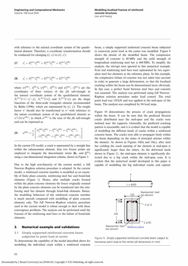
beam, a simply supported reinforced concrete beam subjectedto transverse point load at the centre was modelled. Figure 9shows the details of the modelled beam. The compressivestrength of concrete is 40MPa and the yield strength oflongitudinal reinforcing steel bar is 460MPa. To simplify theanalysis, the stirrups were ignored in this numerical example.Four real reinforcing steel bars were represented by two equiv-alent steel bar elements at the reference plane. In this example,the compressive failure of concrete was not taken into accountin order to generate a large deformation, so that the localisedcracking within the beam can be demonstrated more obviously.In this case, a perfect bond between steel bars and concretewas assumed. The analysis was performed using full Newton–Raphon solution procedure under load control. The totalpoint load was 150 kN and was applied at the mid-span of thebeam. The analysis was completed by 94 load steps.
Figure 10 demonstrates the process of crack propagationswithin the beam. It can be seen that the predicted flexuralcracks distributed near the mid-span and the cracks wereinclined near the supports. Generally, the predicted crackingpattern is reasonable, and it is evident that the model is capableof modelling the different kinds of cracks within a reinforcedconcrete beam. The cracks were able to propagate freely withinthe beam depending on the states of principal stresses withinthe element. As shown in Figures 10(b) and 10(c), after steelbar yielding the crack opening of the element at mid-span issignificantly larger than the others. As the deformed meshshown in Figure 11, the mid-span element is significantly dis-torted due to a big crack within the mid-span zone. It isevident that the numerical model developed in this paper iscapable of modelling the big individual cracks and capture
50
50
250
Reference planeRepresented steelbar element
Represented steelbar element
2 φ 12
120
2 φ 30
P
L = 4000
Figure 9. Simply supported reinforced concrete beam subject totransverse point load at the centre (all dimensions in mm)
62
Engineering and Computational MechanicsVolume 169 Issue EM2
Modelling localised fracture of reinforcedconcrete structuresLiao and Huang
Downloaded by [ Brunel University] on [30/06/16]. Copyright © ICE Publishing, all rights reserved.
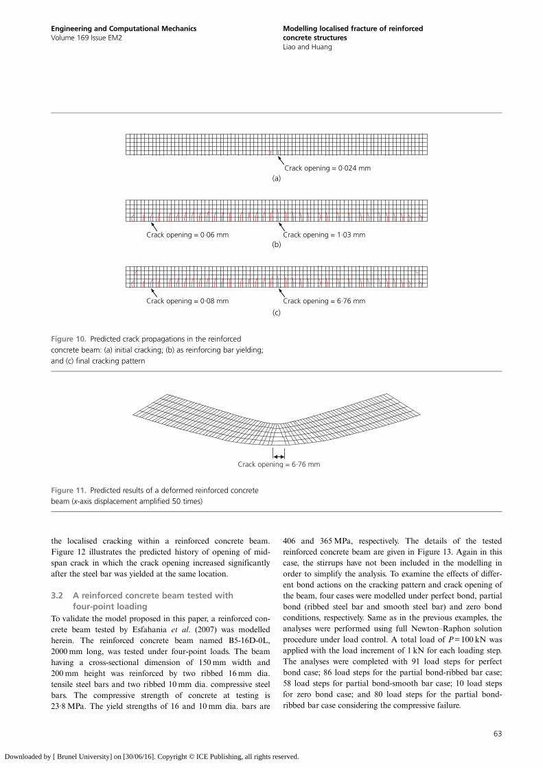
the localised cracking within a reinforced concrete beam.Figure 12 illustrates the predicted history of opening of mid-span crack in which the crack opening increased significantlyafter the steel bar was yielded at the same location.
3.2 A reinforced concrete beam tested withfour-point loading
To validate the model proposed in this paper, a reinforced con-crete beam tested by Esfahania et al. (2007) was modelledherein. The reinforced concrete beam named B5-16D-0L,2000 mm long, was tested under four-point loads. The beamhaving a cross-sectional dimension of 150mm width and200 mm height was reinforced by two ribbed 16mm dia.tensile steel bars and two ribbed 10mm dia. compressive steelbars. The compressive strength of concrete at testing is23·8MPa. The yield strengths of 16 and 10mm dia. bars are
406 and 365MPa, respectively. The details of the testedreinforced concrete beam are given in Figure 13. Again in thiscase, the stirrups have not been included in the modelling inorder to simplify the analysis. To examine the effects of differ-ent bond actions on the cracking pattern and crack opening ofthe beam, four cases were modelled under perfect bond, partialbond (ribbed steel bar and smooth steel bar) and zero bondconditions, respectively. Same as in the previous examples, theanalyses were performed using full Newton–Raphon solutionprocedure under load control. A total load of P=100 kN wasapplied with the load increment of 1 kN for each loading step.The analyses were completed with 91 load steps for perfectbond case; 86 load steps for the partial bond-ribbed bar case;58 load steps for partial bond-smooth bar case; 10 load stepsfor zero bond case; and 80 load steps for the partial bond-ribbed bar case considering the compressive failure.
(a)
(b)
(c)
Crack opening = 6·76 mmCrack opening = 0·08 mm
Crack opening = 1·03 mmCrack opening = 0·06 mm
Crack opening = 0·024 mm
Figure 10. Predicted crack propagations in the reinforcedconcrete beam: (a) initial cracking; (b) as reinforcing bar yielding;and (c) final cracking pattern
Crack opening = 6·76 mm
Figure 11. Predicted results of a deformed reinforced concretebeam (x-axis displacement amplified 50 times)
63
Engineering and Computational MechanicsVolume 169 Issue EM2
Modelling localised fracture of reinforcedconcrete structuresLiao and Huang
Downloaded by [ Brunel University] on [30/06/16]. Copyright © ICE Publishing, all rights reserved.
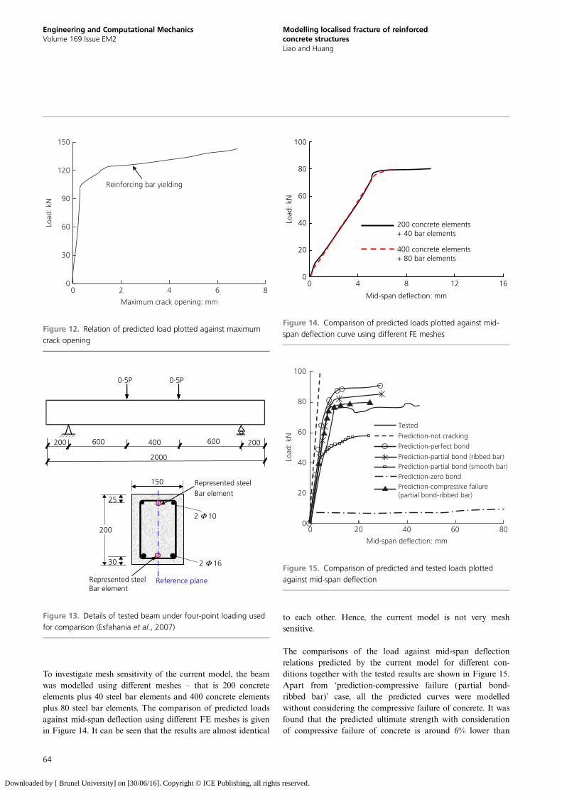
To investigate mesh sensitivity of the current model, the beamwas modelled using different meshes – that is 200 concreteelements plus 40 steel bar elements and 400 concrete elementsplus 80 steel bar elements. The comparison of predicted loadsagainst mid-span deflection using different FE meshes is givenin Figure 14. It can be seen that the results are almost identical
to each other. Hence, the current model is not very meshsensitive.
The comparisons of the load against mid-span deflectionrelations predicted by the current model for different con-ditions together with the tested results are shown in Figure 15.Apart from ‘prediction-compressive failure (partial bond-ribbed bar)’ case, all the predicted curves were modelledwithout considering the compressive failure of concrete. It wasfound that the predicted ultimate strength with considerationof compressive failure of concrete is around 6% lower than
Reinforcing bar yielding
Maximum crack opening: mm
Load
: kN
0 2 4 6 8
150
120
90
60
30
0
Figure 12. Relation of predicted load plotted against maximumcrack opening
Reference plane
0·5P0·5P
200
2000
600 400 600 200
2 Φ 10
150
25
30
200
2 Φ 16
Represented steelBar element
Represented steelBar element
Figure 13. Details of tested beam under four-point loading usedfor comparison (Esfahania et al., 2007)
Load
: kN
Mid-span deflection: mm
200 concrete elements+ 40 bar elements
400 concrete elements+ 80 bar elements
0 4 8 12 16
100
80
60
40
20
0
Figure 14. Comparison of predicted loads plotted against mid-span deflection curve using different FE meshes
Tested
Prediction-not cracking
Prediction-perfect bond
Prediction-partial bond (ribbed bar)Prediction-partial bond (smooth bar)Prediction-zero bondPrediction-compressive failure(partial bond-ribbed bar)
Mid-span deflection: mm
0 20 40 60 80
100
80
60
40
20
0
Load
: kN
Figure 15. Comparison of predicted and tested loads plottedagainst mid-span deflection
64
Engineering and Computational MechanicsVolume 169 Issue EM2
Modelling localised fracture of reinforcedconcrete structuresLiao and Huang
Downloaded by [ Brunel University] on [30/06/16]. Copyright © ICE Publishing, all rights reserved.
that without consideration of compressive failure, due to thefact that the extreme compressive elements of concrete werecrushed after the tensile reinforcing steel bar yielded. Thecurves of the perfect bond case and partial bond-ribbed barcase are generally smooth before the yield of reinforcing bars.This is due to the fact that the reinforcing bars could pick upthe released tensile stresses of the cracked concrete. In the caseof zero bonded condition, the load against mid-span deflectionrelation shows significantly discontinuous characteristic afterthe concrete elements cracked. Generally, the predicted ulti-mate strengths of the beam with consideration of compressivefailure and partial bond (ribbed steel bar) agree well with thetested results. As can be seen in Figure 15, if the concrete isassumed to be not cracking, the predicted result greatly overes-timates the ultimate load and rigidity of the beam. It isobvious that the effects of bond characteristics on the struc-tural behaviour of the beam are significant.
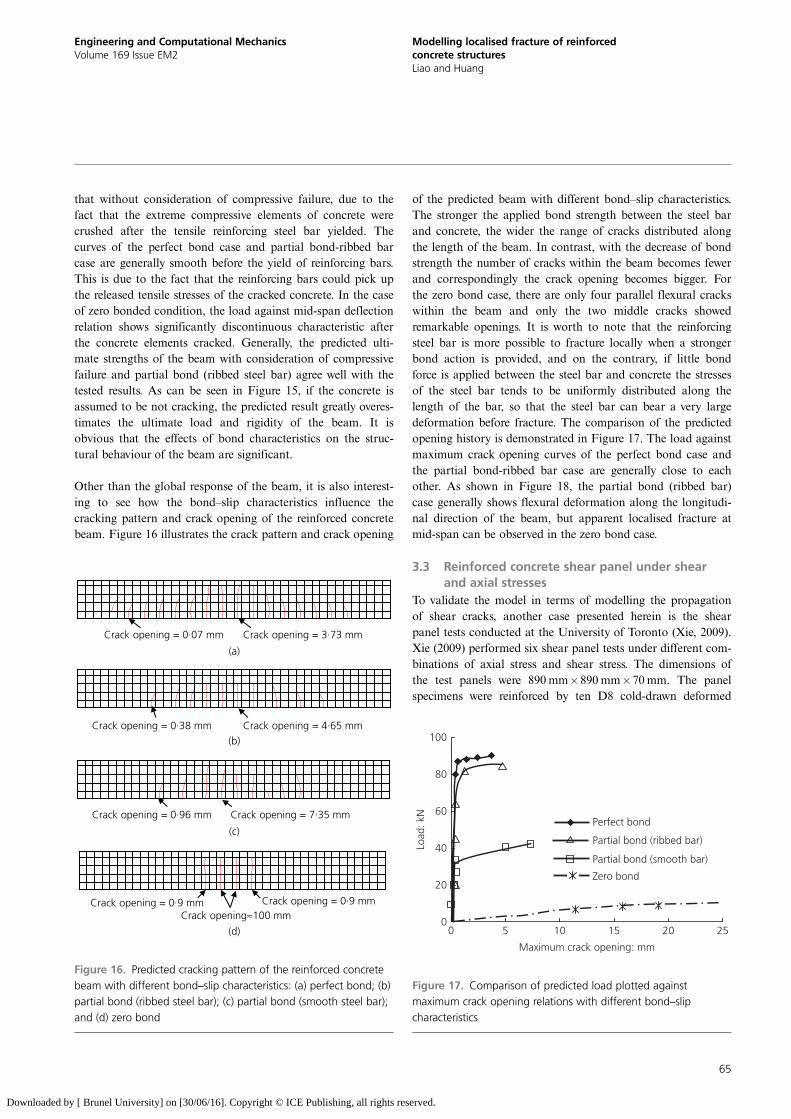
Other than the global response of the beam, it is also interest-ing to see how the bond–slip characteristics influence thecracking pattern and crack opening of the reinforced concretebeam. Figure 16 illustrates the crack pattern and crack opening
of the predicted beam with different bond–slip characteristics.The stronger the applied bond strength between the steel barand concrete, the wider the range of cracks distributed alongthe length of the beam. In contrast, with the decrease of bondstrength the number of cracks within the beam becomes fewerand correspondingly the crack opening becomes bigger. Forthe zero bond case, there are only four parallel flexural crackswithin the beam and only the two middle cracks showedremarkable openings. It is worth to note that the reinforcingsteel bar is more possible to fracture locally when a strongerbond action is provided, and on the contrary, if little bondforce is applied between the steel bar and concrete the stressesof the steel bar tends to be uniformly distributed along thelength of the bar, so that the steel bar can bear a very largedeformation before fracture. The comparison of the predictedopening history is demonstrated in Figure 17. The load againstmaximum crack opening curves of the perfect bond case andthe partial bond-ribbed bar case are generally close to eachother. As shown in Figure 18, the partial bond (ribbed bar)case generally shows flexural deformation along the longitudi-nal direction of the beam, but apparent localised fracture atmid-span can be observed in the zero bond case.
3.3 Reinforced concrete shear panel under shearand axial stresses
To validate the model in terms of modelling the propagationof shear cracks, another case presented herein is the shearpanel tests conducted at the University of Toronto (Xie, 2009).Xie (2009) performed six shear panel tests under different com-binations of axial stress and shear stress. The dimensions ofthe test panels were 890mm890 mm70mm. The panelspecimens were reinforced by ten D8 cold-drawn deformed
(a)
(b)
(c)
(d)
Crack opening = 3·73 mmCrack opening = 0·07 mm
Crack opening = 4·65 mmCrack opening = 0·38 mm
Crack opening = 7·35 mmCrack opening = 0·96 mm
Crack opening≈100 mmCrack opening = 0·9 mmCrack opening = 0·9 mm
Figure 16. Predicted cracking pattern of the reinforced concretebeam with different bond–slip characteristics: (a) perfect bond; (b)partial bond (ribbed steel bar); (c) partial bond (smooth steel bar);and (d) zero bond
Load
: kN
Perfect bond
Partial bond (ribbed bar)
Partial bond (smooth bar)
Zero bond
0 5 10 15 200
20
40
60
25
Maximum crack opening: mm
80
100
Figure 17. Comparison of predicted load plotted againstmaximum crack opening relations with different bond–slipcharacteristics
65
Engineering and Computational MechanicsVolume 169 Issue EM2
Modelling localised fracture of reinforcedconcrete structuresLiao and Huang
Downloaded by [ Brunel University] on [30/06/16]. Copyright © ICE Publishing, all rights reserved.
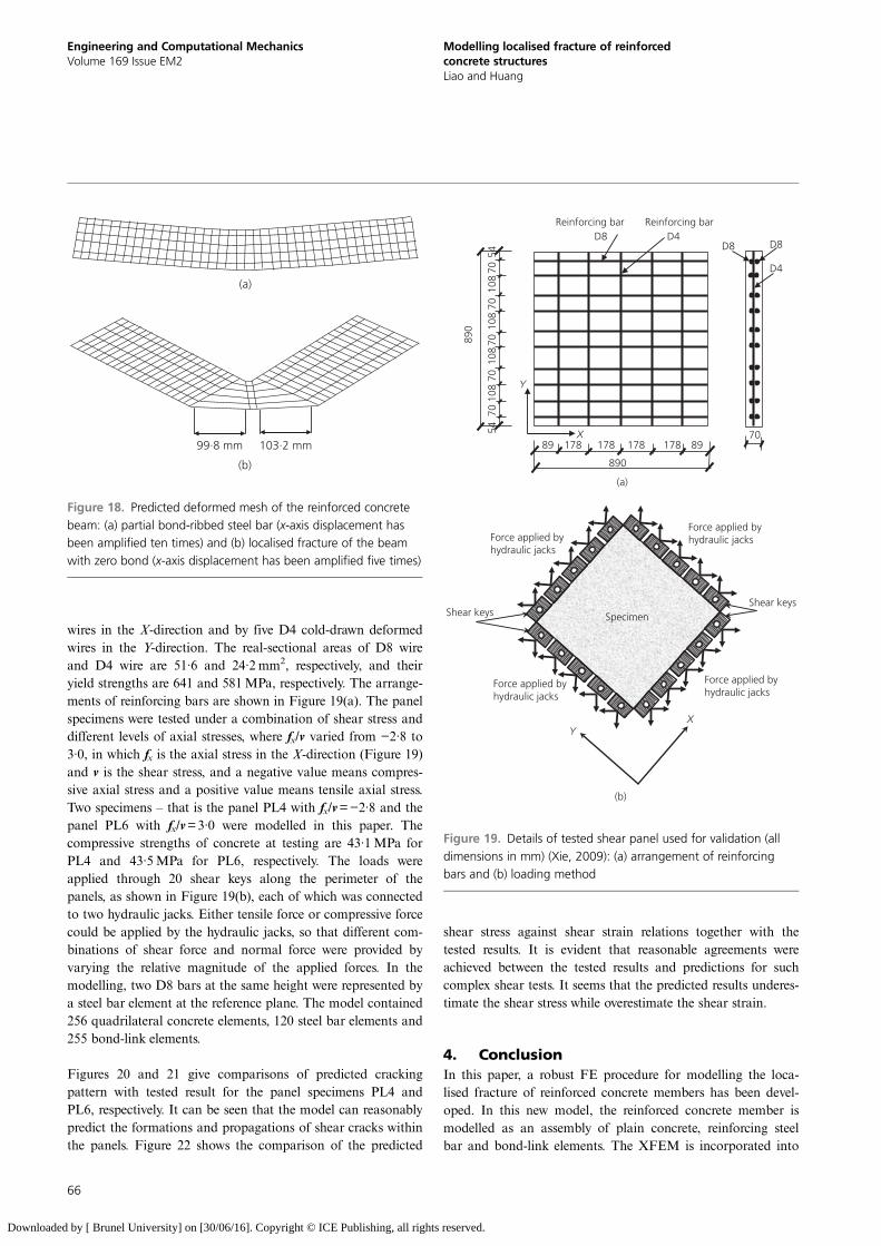
wires in the X-direction and by five D4 cold-drawn deformedwires in the Y-direction. The real-sectional areas of D8 wireand D4 wire are 51·6 and 24·2 mm2, respectively, and theiryield strengths are 641 and 581MPa, respectively. The arrange-ments of reinforcing bars are shown in Figure 19(a). The panelspecimens were tested under a combination of shear stress anddifferent levels of axial stresses, where fx/v varied from −2·8 to3·0, in which fx is the axial stress in the X-direction (Figure 19)and v is the shear stress, and a negative value means compres-sive axial stress and a positive value means tensile axial stress.Two specimens – that is the panel PL4 with fx/v=−2·8 and thepanel PL6 with fx/v=3·0 were modelled in this paper. Thecompressive strengths of concrete at testing are 43·1MPa forPL4 and 43·5MPa for PL6, respectively. The loads wereapplied through 20 shear keys along the perimeter of thepanels, as shown in Figure 19(b), each of which was connectedto two hydraulic jacks. Either tensile force or compressive forcecould be applied by the hydraulic jacks, so that different com-binations of shear force and normal force were provided byvarying the relative magnitude of the applied forces. In themodelling, two D8 bars at the same height were represented bya steel bar element at the reference plane. The model contained256 quadrilateral concrete elements, 120 steel bar elements and255 bond-link elements.
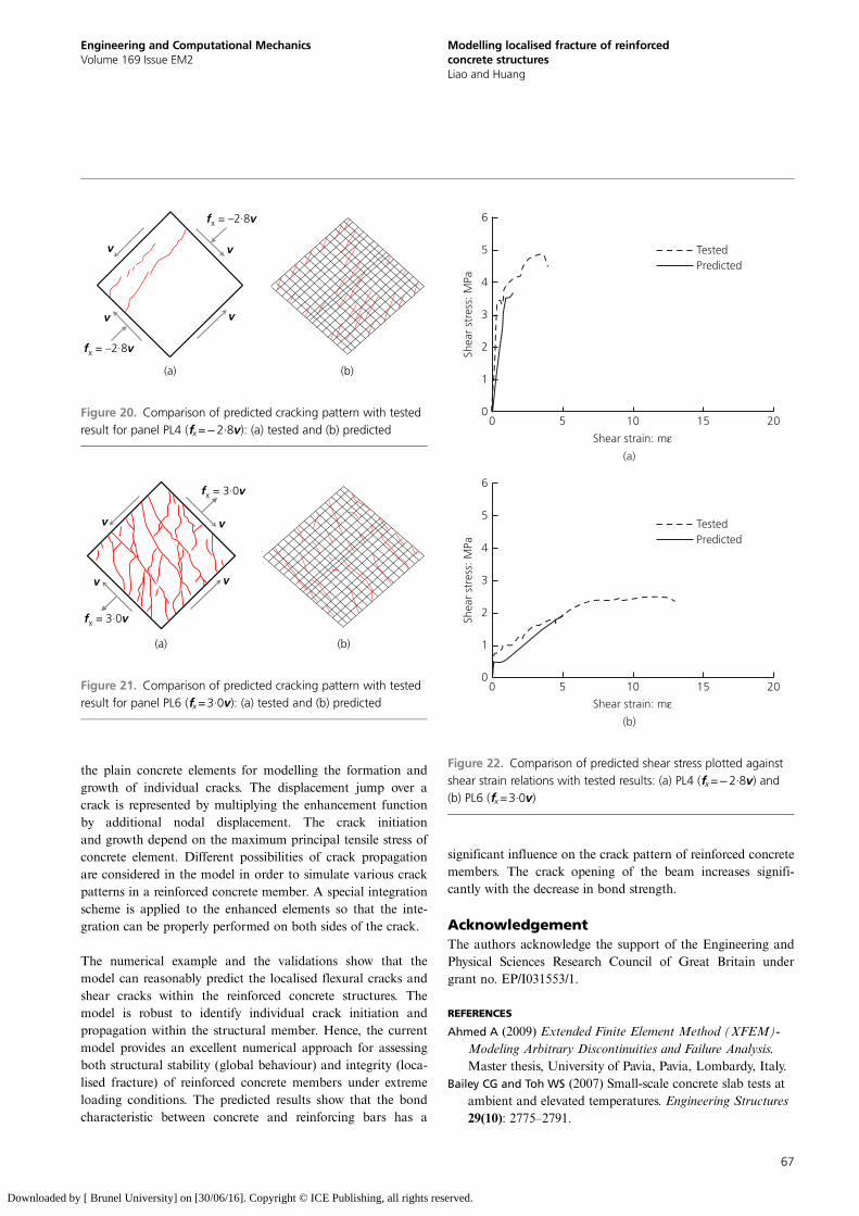
Figures 20 and 21 give comparisons of predicted crackingpattern with tested result for the panel specimens PL4 andPL6, respectively. It can be seen that the model can reasonablypredict the formations and propagations of shear cracks withinthe panels. Figure 22 shows the comparison of the predicted
shear stress against shear strain relations together with thetested results. It is evident that reasonable agreements wereachieved between the tested results and predictions for suchcomplex shear tests. It seems that the predicted results underes-timate the shear stress while overestimate the shear strain.
4. ConclusionIn this paper, a robust FE procedure for modelling the loca-lised fracture of reinforced concrete members has been devel-oped. In this new model, the reinforced concrete member ismodelled as an assembly of plain concrete, reinforcing steelbar and bond-link elements. The XFEM is incorporated into
99·8 mm 103·2 mm
(a)
(b)
Figure 18. Predicted deformed mesh of the reinforced concretebeam: (a) partial bond-ribbed steel bar (x-axis displacement hasbeen amplified ten times) and (b) localised fracture of the beamwith zero bond (x-axis displacement has been amplified five times)
(a)
(b)
Reinforcing bar D8
D8 D8
D4
890
70
890
Reinforcing barD4
X
Y
5470
108
7010
870
108
7010
870
54
89 178 178 178 178 89
Shear keys
XY
Specimen
Force applied byhydraulic jacks
Force applied byhydraulic jacks
Force applied byhydraulic jacks
Force applied byhydraulic jacks
Shear keys
Figure 19. Details of tested shear panel used for validation (alldimensions in mm) (Xie, 2009): (a) arrangement of reinforcingbars and (b) loading method
66
Engineering and Computational MechanicsVolume 169 Issue EM2
Modelling localised fracture of reinforcedconcrete structuresLiao and Huang
Downloaded by [ Brunel University] on [30/06/16]. Copyright © ICE Publishing, all rights reserved.
the plain concrete elements for modelling the formation andgrowth of individual cracks. The displacement jump over acrack is represented by multiplying the enhancement functionby additional nodal displacement. The crack initiationand growth depend on the maximum principal tensile stress ofconcrete element. Different possibilities of crack propagationare considered in the model in order to simulate various crackpatterns in a reinforced concrete member. A special integrationscheme is applied to the enhanced elements so that the inte-gration can be properly performed on both sides of the crack.
The numerical example and the validations show that themodel can reasonably predict the localised flexural cracks andshear cracks within the reinforced concrete structures. Themodel is robust to identify individual crack initiation andpropagation within the structural member. Hence, the currentmodel provides an excellent numerical approach for assessingboth structural stability (global behaviour) and integrity (loca-lised fracture) of reinforced concrete members under extremeloading conditions. The predicted results show that the bondcharacteristic between concrete and reinforcing bars has a
significant influence on the crack pattern of reinforced concretemembers. The crack opening of the beam increases signifi-cantly with the decrease in bond strength.
AcknowledgementThe authors acknowledge the support of the Engineering andPhysical Sciences Research Council of Great Britain undergrant no. EP/I031553/1.
REFERENCES
Ahmed A (2009) Extended Finite Element Method (XFEM)-Modeling Arbitrary Discontinuities and Failure Analysis.Master thesis, University of Pavia, Pavia, Lombardy, Italy.
Bailey CG and Toh WS (2007) Small-scale concrete slab tests atambient and elevated temperatures. Engineering Structures29(10): 2775–2791.
v
v
fx = 3·0v
fx = 3·0v
v
v
(a) (b)
Figure 21. Comparison of predicted cracking pattern with testedresult for panel PL6 (fx=3·0v): (a) tested and (b) predicted
vv
v
fx = –2·8v
fx = –2·8v
v
(a) (b)
Figure 20. Comparison of predicted cracking pattern with testedresult for panel PL4 (fx=−2·8v): (a) tested and (b) predicted
0 5 10 15 20
0 5 10 15 20
Shear strain: mε
6
5
4
3
2
1
0
Shea
r st
ress
: MPa
Shear strain: mε
6
5
4
3
2
1
0
Shea
r st
ress
: MPa
TestedPredicted
TestedPredicted
(a)
(b)
Figure 22. Comparison of predicted shear stress plotted againstshear strain relations with tested results: (a) PL4 (fx=−2·8v) and(b) PL6 (fx=3·0v)
67
Engineering and Computational MechanicsVolume 169 Issue EM2
Modelling localised fracture of reinforcedconcrete structuresLiao and Huang
Downloaded by [ Brunel University] on [30/06/16]. Copyright © ICE Publishing, all rights reserved.
Barzegar-Jamshidi F (1987) Non-linear Finite Element Analysisof Reinforced Concrete Under Short Term MonotonicLoading. PhD thesis, University of Illinois at Urbana-Champaign, Champaign, IL, USA.
Bathe KJ (1996) Finite Element Procedures. Prentice-Hall Inc.,Upper Saddle River, NJ, USA.
Bazant ZP and Becq-Giraudon E (2002) Statistical prediction offracture parameters of concrete and implications for choiceof testing standard. Cement and Concrete Research 32(4):529–556.
Belytschko T and Black T (1999) Elastic crack growth in finiteelements with minimal remeshing. International Journal forNumerical Methods in Engineering 45(5): 601–620.
BSI (2004) BS EN 1992-1-1: Eurocode 2: Design of concretestructures. Part 1.1: general rules and rules for buildings.BSI, London, UK.
CEB-FIP (Comité Euro-International du Béton) (1993) CEB-FIPModel Code 1990. Redwood Books, Trowbridge,Wiltshire, UK.
Cervenka V, Cervenka J and Jendele L (2003) Bond infinite element modelling of reinforced concrete.In Proceedings of the EURO-C Conference onthe Computational Modelling of Concrete Structures(Bicanic N, Borst RD, Mang H and Meschke G (eds)).A.A. Balkema Publishers, Lisse, the Netherlands,pp. 189–194.
Chen GM, Teng JG and Chen JF (2011) Finite-element modelingof intermediate crack debonding in FRP-plated RC beams.Journal of Composites for Construction ASCE 15(3):339–353.
Duan Q, Song JH, Menouillard T and Belytschko T (2009)Element-local level set method for three-dimensionaldynamic crack growth. International Journal forNumerical Methods in Engineering 80(12): 1520–1543.
Esfahania MR, Kianoushb MR and Tajaria AR (2007)Flexural behaviour of reinforced concrete beamsstrengthened by CFRP sheets. Engineering Structures29(10): 2428–2444.
Foster SJ (2006) Tensile Membrane Action of ReinforcedConcrete Slabs at Ambient and Elevated Temperatures.PhD thesis, Department of Civil and StructuralEngineering, University of Sheffield, Sheffield, UK.
Foster SJ, Bailey CG, Burgess IW and Plank RJ (2004)Experimental behaviour of concrete floor slabs atlarge displacement. Engineering Structures 26(9):1231–1247.
Gao WY, Dai JG, Teng JG and Chen GM (2013) Finite elementmodeling of reinforced concrete beams exposed to fire.Engineering Structures 52(7): 488–501.
Gravouil A, Möes N and Belytschko T (2002) Non-planar 3Dcrack growth by the extended finite element and levelsets – part II: level set update. International Journal forNumerical Methods in Engineering 53(11): 2569–2586.
Hansbo A and Hansbo P (2004) A finite element method for thesimulation of strong and weak discontinuities in solidmechanics. Computer Methods in Applied Mechanics andEngineering 193(33–35): 3523–3540.
Huang Z (2010) Modelling the bond between concrete andreinforcing steel in a fire. Engineering Structures 32(11):3660–3669.
Huang Z, Burgess IW and Plank RJ (2003) Modelling membraneaction of concrete slabs in composite buildings in fire.Part I: theoretical development. Journal of StructuralEngineering ASCE 129(8): 1093–1102.
Huang Z, Burgess IW and Plank RJ (2009) Three-dimensionalanalysis of reinforced concrete beam–column structures infire. Journal of Structural Engineering ASCE 135(10):1201–1212.
Küpfer HB and Gerstle KH (1973) Behavior of concrete underbiaxial stresses. Journal of the Engineering MechanicsDivision ASCE 99(EM4): 853–866.
Mellenk JM and Babuska I (1996) The partition of unity finiteelement method: basic theory and application. ComputerMethods in Applied Mechanics and Engineering 139(1–4):289–314.
Möes N and Belytschko T (2002) Extended finite elementmethod for cohesive crack growth. Engineering FractureMechanics 69(7): 813–833.
Möes N, Dolbow J and Belytschko T (1999) A finite elementmethod for crack growth without remeshing. InternationalJournal for Numerical Methods in Engineering 46(1):131–150.
Möes N, Gravouil A and Belytschko T (2002) Non-planar 3Dcrack growth by the extended finite element and level sets –part I: mechanical model. International Journal forNumerical Methods in Engineering 53(11): 2549–2568.
Rots JG (1985) Bond–Slip Simulation Using Smeared Cracksand/or Interface Element. Structural Mechanics Group,Department of Civil Engineering, Delft University ofTechnology, Delft, the Netherlands, Research Report85.01.
Suidan M and Schnobrich WC (1973) Finite element analysis ofreinforced concrete. Journal of the Structural DivisionASCE 99(10): 2109–2122.
Sukumar N, Möes N, Moran B and Belytschko T (2000) Extendedfinite element method for three-dimensional crackmodelling. International Journal for Numerical Methods inEngineering 48(11): 1549–1570.
Vecchio FJ and DeRoo A (1995) Smeared-crack modelling ofconcrete tension splitting. Journal of EngineeringMechanics ASCE 121(6): 702–708.
Verhoose CV, Remmers JJC and Gutierrez MA (2009) Adissipation-based arc-length method for robustsimulation of brittle and ductile failure. InternationalJournal for Numerical Methods in Engineering 77(9):1290–1321.
68
Engineering and Computational MechanicsVolume 169 Issue EM2
Modelling localised fracture of reinforcedconcrete structuresLiao and Huang
Downloaded by [ Brunel University] on [30/06/16]. Copyright © ICE Publishing, all rights reserved.
Wells GN and Sluys LJ (2001) A new method for modellingcohesive cracks using finite elements. International Journalfor Numerical Methods in Engineering 50(12): 2667–2682.
Xiao QZ, Karihaloo BL and Liu XY (2007) Incremental-secantmodulus iteration scheme and stress recovery forsimulating cracking process in quasi-brittle materials usingXFEM. International Journal for Numerical Methods inEngineering 69(12): 2606–2635.
Xie LP (2009) The Influence of Axial Load and Prestress on theShear Strength of Web-Shear Critical Reinforced ConcreteElements. PhD thesis, Department of Civil Engineering,University of Toronto, Toronto, Canada.
Zi G and Belytschko T (2003) New crack-tip elements forXFEM and applications to cohesive cracks. InternationalJournal for Numerical Methods in Engineering 57(15):2221–2240.
WHAT DO YOU THINK?
To discuss this paper, please email up to 500 words to theeditor at [email protected]. Your contribution will beforwarded to the author(s) for a reply and, if consideredappropriate by the editorial panel, will be published asdiscussion in a future issue of the journal.
Proceedings journals rely entirely on contributions sent inby civil engineering professionals, academics and stu-dents. Papers should be 2000–5000 words long (briefingpapers should be 1000–2000 words long), with adequateillustrations and references. You can submit your paperonline via www.icevirtuallibrary.com/content/journals,where you will also find detailed author guidelines.
69
Engineering and Computational MechanicsVolume 169 Issue EM2
Modelling localised fracture of reinforcedconcrete structuresLiao and Huang
Downloaded by [ Brunel University] on [30/06/16]. Copyright © ICE Publishing, all rights reserved.