model: zm 110 - digital-scales-company.co.uk
TRANSCRIPT

AWT35-501813 Issue AA Page 1
User Manual Model: ZM 110
Bench Scale

AWT35-501813 Issue AA Page 2
Avery Weigh-Tronix is a trademark of the Illinois Tool Works group of companies whose ultimate parent company is Illinois Tool Works Inc (“Illinois Tool Works”). Copyright © 2019 Illinois Tool Works. All rights reserved.
No part of this publication may be reproduced, stored in an electronic retrieval system, or transmitted in any form or by any means, electronic, mechanical, photocopying, recording or otherwise without the prior written consent of the copyright owner, or as permitted by law or under license. Full acknowledgment of the source must be given. Avery Weigh-Tronix is a registered trade mark of the Avery Weigh-Tronix group of companies. This publication was correct at the time of going to print however, Avery Weigh-Tronix reserves the right to alter without notice the specification, design, price or conditions of supply of any product or service at any time.
All third party brands and product names used within this document are trademarks or registered trademarks of their respective holders. © Groupe de sociétés Avery Weigh-Tronix, 2019. Tous droits réservés.
Aucune partie de cette publication ne peut être reproduite, enregistrée dans un système de récupération électronique ou transmise sous quelque forme ou par quelque moyen que ce soit, électronique ou mécanique, par photocopie, enregistrement ou autre, sans l’accord écrit préalable du propriétaire du droit d’auteur ou tel qu’autorisé par la loi ou dans le cadre d’une licence. La source doit être reconnue dans son intégralité. Avery Weigh-Tronix est une marque déposée du groupe de sociétés Avery Weigh-Tronix. Le contenu de cette publication était correct au moment de sa mise sous presse. Toutefois, Avery Weigh-Tronix se réserve le droit de modifier à tout moment et sans préavis les spécifications, la conception, les tarifs ou les conditions d’approvisionnement de tout produit ou service.
Toutes les marques et tous les noms de produits tiers utilisés dans ce document sont des marques de commerce ou des marques déposées de leurs propriétaires respectifs. ZM110_u_en_501860.docx
AWT35-501813 Issue AA Page 3
Table of Contents
1. General information and Warnings page 6
FCC Declaration of Compliance - Déclaration de conformité..……...…………..… 6
Training - Formation……………………..………………………………...…………… 6
Battery Safe Disposal - Élimination sécurisée des batteries……...………………… 7
Routine Maintenance - Entretien de routine……………………………………..… 7
Cleaning the Machine - Nettoyage de la machine………………………….……… 7
Sharp Objects - Objets tranchants………………………….………………...…….... 7
2. Introduction page 8
Unpacking…………………………………….………………………..………………….. 8
General Installation Guidelines……………………….…...……………………………. 8
Battery Operation…………………………….………………………..…………………. 10
Powering ON/OFF the Scale………………………………………………………….… 10
Front Panel………...…………………………………….……………………………...... 10
Error Codes………..…………………………………….……………………………...... 11
3. Scale Operation page 12
Gross Weighing…………………………………………………………………………… 12
Tare Weighing.………………..……………………………………….………….………. 12
Clear a Tare………………….……………………….……………………………….. 12
Counting Mode…………………………………………………………………………….. 13
Sampling Parts Prior to Counting.………………….……………………………….. 13
Checkweighing Mode....……..………………………………….…….………….………. 13
Setting the Checkweighing Limits………………….……………………………….. 14
Checkweighing Beeper Modes…………………………..………………………….. 14
Hold Mode for Animal Weighing………………………………………......……..……… 14
4. Menus page 15

AWT35-501813 Issue AA Page 4
User Menu……………………..……………………………...……….………….……..…. 15
User Menu Levels………………….………………...……….……………………..… 15
User Functions Descriptions [UF].………………….……….…………………..…… 16
Supervisor Menu....………………………….……………..………………….……..……. 17
Supervisor Menu Levels……..……….………………………………………..……... 17
Supervisor Functions Descriptions [LF].…………..….……………………..….…... 17
Quick Calibration Menu……..………………………..……………………….……..……. 18
Quick Calibration Menu Levels…...…………….……………………...……..……… 18
Quick Calibration Functions Descriptions [ECF]…..…………………………..…… 18
5. Scale Configuration [LF 2] page 19
6. Calibration page 20
Enabling the Calibration Procedure..….……………………………………………….. 20
Scale Calibration Procedure...………….……………………………………………….. 20
Stamped Calibration……….....………….……………………………………………….. 21
7. Replacement Parts
page 22
9. Loadcell Pinouts
page 22

AWT35-501813 Issue AA Page 5
Manual revision history
Current Issue Date Created Details of Changes
Draft Jan. 2019 New
Please be aware this product contains a lead acid battery which MUST be removed and disposed of safely prior to any disposal of the scale.

AWT35-501813 Issue AA Page 6
1. General Information and Warnings
1.1. FCC Declarations of Compliance - FCC Déclaration de conformité
United States
This equipment has been tested and found to comply with the limits for a Class A digital device, pursuant to Part 15 of the FCC Rules. These limits are designed to provide reasonable protection against harmful interference when the equipment is operated in a commercial environment. This equipment generates, uses, and can radiate radio frequency energy and, if not installed and used in accordance with the instruction manual, may cause harmful interference to radio communications. Operation of this equipment in a residential area is likely to cause harmful interference in which case the user will be required to correct the interference at his own expense.
Canada
This digital apparatus does not exceed the Class A limits for radio noise emissions from digital apparatus set out in the Radio Interference Regulations of the Canadian Department of Communications.
Le présent appareil numérique n’émet pas de bruits radioélectriques dépassant les limites applicables aux appareils numériques de la Classe A prescrites dans le Règlement sur le brouillage radioélectrique edicté par le ministère des Communications du Canada.Interference Regulations of the Canadian Department of Communications.

AWT35-501813 Issue AA Page 7
1.2. Training - Formation Do not attempt to operate or complete any procedure on a machine unless you have received the appropriate training or read the instruction books.
Ne pas tenter d’utiliser la machine ou lui appliquer une quelconque procédure sans avoir reçu une formation adaptée ou lu les manuels d’instruction.
CAUTION! Risk of electrical shock. Refer to qualified service personnel for service.
ATTENTION! Risque de choc électrique. Confier la réparation de l’appareil à un personnel qualifié.
1.3. Safe Battery Disposal - Élimination sécurisée des batteries Please be aware this product contains a lead acid battery which MUST be removed and disposed of safely prior to any disposal of the scale. This battery can be easily accessed by removing the battery cover found on the underside of the indicator.
CAUTION! Danger of explosion if battery is incorrectly replaced. Replace only with
the same or equivalent type recommended by the manufacturer.
ATTENTION! Il y a danger d'explosion s'il y a remplacement incorrect de la batterie, remplacer uniquement avec une batterie du même type ou d'un type équivalent recommandé par le constructeur.
1.4. Routine Maintenance - Entretien de routine IMPORTANT: This equipment must be routinely checked for proper operation and calibration. Application and usage will determine the frequency of calibration required for safe operation.
PRUDENCE: Le fonctionnement et l’étalonnage de cet équipement doivent être vérifiés régulièrement. Les applications et l’utilisation déterminent la fréquence de l’étalonnage requis pour une utilisation en toute sécurité. 1.5. Cleaning of Scale - Nettoyage de la machine
Do - Ce qu’il faut faire Do NOT - Ce qu’il ne faut pas faire
Wipe down the outside of product with a clean cloth, moistened with water and a small amount of mild detergent cleaning fluid.
Essuyer la partie externe des produits standard à l’aide d’un chiffon propre légèrement imprégné d’eau et d’une petite quantité de détergent doux.
Use harsh abrasives, solvents, scouring cleaners or alkaline cleaning solutions.
Utiliser des produits abrasifs, des solvants, des produits de récurage ou des solutions de nettoyage alcalines.
Spray on to the cloth when cleaning and not directly onto the indicator area.
Pulvériser tout produit de nettoyage spécifique sur le chiffon.
Do not attempt to clean the inside of the machine.
Tenter de nettoyer l’intérieur de la machine.
Spray any liquid directly on to the display windows.
Pulvériser des liquides directement sur les écrans d’affichage.
1.6. Sharp Objects - Objets tranchants Do not use any sharp objects such as screwdrivers or long fingernails to operate the keys.
Ne pas appuyer sur les touches avec des objets tranchants tels que des tournevis ou même des ongles longs.

AWT35-501813 Issue AA Page 8
2. Introduction
The ZM110 is a general purpose indicator ideal for connecting to most bench and floor scales. This indicator can easily be desk or pole mounted and comes with an AC power adaptor along with a rechargeable lead acid battery to allow the scale to be used in applications where power outlets are limited. This ZM110 indicator comes standard with a range of easy to operate General weighing functions along with basic Checkweighing and Counting.
2.1 Unpacking Carefully take the scale out of its package, make it sure it’s not damaged and all accessories are included.
• Remove the scale from the carton;
• Remove the protective covering;
• Inspect the scale and indicator/display for damage;
• Make sure all components are included:
1. ZM110 Indicator
2. Adaptor plus plug adaptors
3. Platform, column and brackets
4. Product manual
2.2. General Installation Guidelines To get the best performance from the scale, place the ZM110 in a location that will not degrade its
accuracy.
• Avoid extremes of temperature. Try to avoid placing the scale in direct sunlight or near air vents;
• Place the scale on a level flat surface. Do not place the scale near vibrating machinery;
• Avoid unstable power sources. Do not use near welding equipment or other large users of electricity.
2.2.1 Levelling the Scale Level the scale using the four adjustable feet on the bottom of the scale, Figure 1, and the bubble level near the base of the column, Figure 2.
Always check the level prior to using scale.
Fig. 1 Adjust scale feet to level the scale Fig. 2 Adjust feet until bubble is centered in the black circle

AWT35-501813 Issue AA Page 9
2.2.2 Scale Installation
1. Attach the support column to the bracket at the back of the scale base using the three mounting screws. Use a 3mm hex (Allen) key to tighten the screws. See Figure 3.
Fig. 3 Insert column into bracket and secure with three screws
2. Place the indicator on the top bracket as shown in Figure 4 and slide it down until it snaps into the final position. Loosen the adjustment knob shown in Figure 4 and adjust the indicator’s angle for best viewing of the display, then tighten the knob.
Fig. 4 Slide indicator head onto column bracket
3. The cable from the base to the indicator is run through the column and out through the plastic bracket at the top when you unpack the scale. Make sure the connector is free of obstructions, i.e. packing foam, and plug the cable into the connector, as shown in Figure 5. Tighten the threaded collar.
4. Attach the AC power adapter to the connector on the back of the indicator. See Figure 5.
Fig. 5 Signal cable plugged into back of the indicator

AWT35-501813 Issue AA Page 10
2.3. Battery Operation The ZM110 can be operated from a 6V 4Ahrs battery located inside the indicator or plugged into an acceptable power outlet. Battery life is approximately 107 hours with the backlight off.
When the battery needs charging this symbol, , appears in the upper left corner of the weight display. The scale will still operate for about 10 hours after which it will automatically switch off to protect the battery.
When the scale is turned on, the battery status is shown by:
- Green LED, battery is fully charged;
- Red LED, battery is low and needs to be recharged.
Do not use any other type of power adaptor other than the one supplied with the scale and verify that the AC power socket outlet is properly protected.
Charge the battery for at least 12 hours before using.
2.4. Powering On/Off the Scale With the platform connected and the battery fully charged or the charger plugged into the indicator, press the ON key to power ON the scale. A display test will be performed on power up and the scale will finish in normal weighing mode. Press the OFF key to turn the scale off.
2.5. Front Panel The indicator has a sealed keypad and a 6 digit LCD display, 0.59” (40mm) high with white backlight. Only active annunciators are shown below.
2.5.1. Display Annunciators
Display reading is stable
Scale at Zero
NET Indicates a Net weight
GROSS Indicates a Gross weight
Under acceptable weight range
Within acceptable weight range
Over acceptable weight range
Battery needs to be recharged
kg lb g Current unit of measure

AWT35-501813 Issue AA Page 11
2.5.2. Operation Keys
Keys are shown below along with their functions. Some keys have secondary functions.
Press and hold the OFF key to turn off the scale. “oFF” will be displayed for 2 seconds.
Press the ON key to turn on the scale. The scale will run through a display test before displaying 0.000.
- Press the UNITS key to scroll through the active units of measure. - In Menu mode: It aborts a numeric entry and acts as an ESCAPE key (ESC).
- Press the ZERO key to zero the scale. Enabled only within the ±2% range of
capacity.
- In Menu mode: It acts as a left arrow key (◄).
- Press the TARE key to perform a tare function.
- In Menu mode: It acts as a right arrow key (►).
- Press the SELECT key to toggle between the operating modes enabled.
- In Menu mode: It increments a numeric value (▲).
- Press the PRINT key to send information to a peripheral device.
- In Menu mode: It acts as an ENTER key to accept a displayed value or function (↵).
2.6. Error Codes
Err H Initial zero too high (over FULL SCALE + 10%), for approved models [LF 6]
Err L Initial zero too low (under FULL SCALE – 10%), for approved models [LF 6]
Err N Unstable internal count, this may indicate the load cell or electronics are faulty
-OL- Overload, full capacity +9d

AWT35-501813 Issue AA Page 12
3. Scale Operation This section covers the scale operations of simple weighing, counting and hold. The steps for various kinds of weighing are explained in the following pages.
A warm-up time of 15 minutes is required to stabilize the measured values.
3.1. Gross Weighing To perform a gross weighment, follow these steps:
1. Power up the scale. Be sure the scale is displaying weight in the correct unit of measure. Press the UNITS key, if necessary to change the units of measure the scale is working in.
2. Zero the scale if necessary by pressing the ZERO key. If the weight change is within the Zero window area the display will show 0.000. Decimal positions available may vary.
3. Place the item(s) to be weighed on the scale platform.
4. The display will now display the weight of the item that is on the weight platter
3.2. Tare Weighing If you want to do NET weighing, such as weighing objects in a container, follow these steps:
1. Power up the scale. Be sure the scale is displaying weight in the correct unit of measure. Press the UNITS key, if necessary to change the units of measure the scale is working in.
2. Zero the scale if necessary by pressing the ZERO key. If the weight change is within the Zero window area the display will show 0.000. Decimal positions available may vary.
3. Place the item to be tared on the scale platform.
4. Press the TARE key. If the container weight is outside the Zero window area the display will show 0.000 weight and the NET annunciator is illuminated. Decimal positions available may vary.
5. Place the item to be weighed on the scale platform. Net weight of the item is displayed. Press the SELECT key to choose the Gross or Net weight.
Example: annunciators lit when tare weighing with 5 kg box and 10kg of items.
3.2.1. Clear a Tare Remove any load from the scale and press the TARE key until that 0.000 is displayed. Decimal positions available may vary.
Example: annunciators lit when clearing a 5 kg cointaner tare
AWT35-501813 Issue AA Page 13
3.3. Counting Mode The ZM110 Counting mode has been designed to allow the operator to easily carry out basic sampling and counting routines on this scale even if the scale is mainly used for general weighing applications. By pressing the UNITS key until Pcs is illuminated on the display, the scale can now be quickly used to sample parts ready for counting.
For count accuracy, all items should be uniform in weight and UF-5 set as HOLD 0. It is recommended that the sample weight be a minimum of 0.1% of scale capacity.
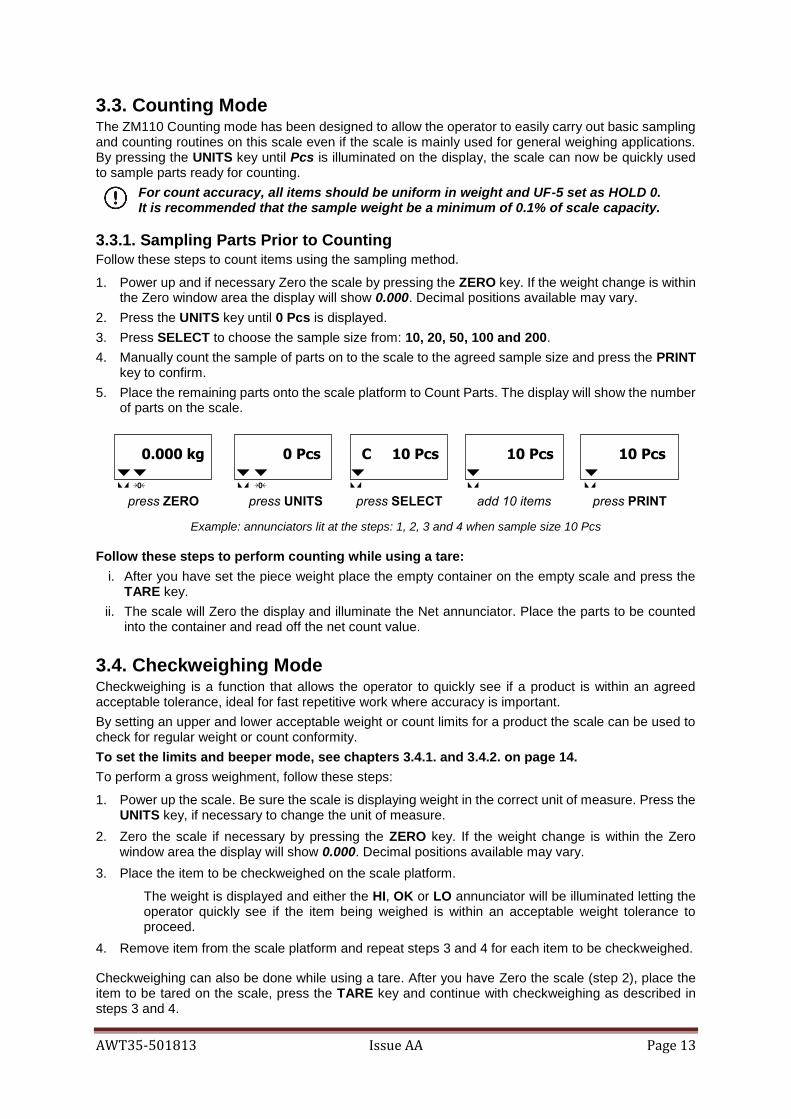
3.3.1. Sampling Parts Prior to Counting Follow these steps to count items using the sampling method.
1. Power up and if necessary Zero the scale by pressing the ZERO key. If the weight change is within the Zero window area the display will show 0.000. Decimal positions available may vary.
2. Press the UNITS key until 0 Pcs is displayed.
3. Press SELECT to choose the sample size from: 10, 20, 50, 100 and 200.
4. Manually count the sample of parts on to the scale to the agreed sample size and press the PRINT key to confirm.
5. Place the remaining parts onto the scale platform to Count Parts. The display will show the number of parts on the scale.
Example: annunciators lit at the steps: 1, 2, 3 and 4 when sample size 10 Pcs
Follow these steps to perform counting while using a tare:
i. After you have set the piece weight place the empty container on the empty scale and press the TARE key.
ii. The scale will Zero the display and illuminate the Net annunciator. Place the parts to be counted into the container and read off the net count value.
3.4. Checkweighing Mode Checkweighing is a function that allows the operator to quickly see if a product is within an agreed acceptable tolerance, ideal for fast repetitive work where accuracy is important.
By setting an upper and lower acceptable weight or count limits for a product the scale can be used to check for regular weight or count conformity.
To set the limits and beeper mode, see chapters 3.4.1. and 3.4.2. on page 14.
To perform a gross weighment, follow these steps:
1. Power up the scale. Be sure the scale is displaying weight in the correct unit of measure. Press the UNITS key, if necessary to change the unit of measure.
2. Zero the scale if necessary by pressing the ZERO key. If the weight change is within the Zero window area the display will show 0.000. Decimal positions available may vary.
3. Place the item to be checkweighed on the scale platform.
The weight is displayed and either the HI, OK or LO annunciator will be illuminated letting the operator quickly see if the item being weighed is within an acceptable weight tolerance to proceed.
4. Remove item from the scale platform and repeat steps 3 and 4 for each item to be checkweighed.
Checkweighing can also be done while using a tare. After you have Zero the scale (step 2), place the item to be tared on the scale, press the TARE key and continue with checkweighing as described in steps 3 and 4.

AWT35-501813 Issue AA Page 14
Example: annunciators lit when acceptable limits are: LO < 1.00 kg and HI > 4.00 kg
3.4.1. Setting the Checkweighing Limits
i. When the scale is ON, press PRINT and TARE keys together;
UF-1 will be displayed.
ii. Press TARE (►) key;
UF-2 will be displayed.
iii. Press PRINT(↵) key;
iv. Enter or edit the LO limit value by pressing ZERO(◄) and/or TARE (►) keys to move the flashing digit left or right and press the SELECT (▲) key to increase the numeric value;
v. Press PRINT (↵) key to confirm;
vi. Repeat points iv. and v. for the HI limit;
vii. Choose the beeper mode [000; 001; 002; See Section 3.3.2 ] by pressing ZERO(◄) and/or TARE (►) keys to move the flashing digit left or right and press the SELECT (▲) key to increase the numeric value;
viii. Press PRINT (↵) key to complete and leave the procedure;
ix. Press UNITS (ESC) key to exit the User Menu.
To disable the checkweighing feature, set the LO limits to 0 in the User Menu [UF-2]. The LO and HI annunciators may vary. The illustration shows the annunciators displayed when acceptable limits are entered for first time.
3.3.2. Checkweighing Beeper Modes There are three beeper modes.
o 000 The beeper is disabled.
o 001 The beeper tones only when the load is within the acceptable limits.
o 002 The beeper tones only when the load is outside the acceptable limits.
Please, ignore any other mode not listed above.
3.5. Hold Mode for Animal Weighing Hold mode is not available in this model.

AWT35-501813 Issue AA Page 15
4. Menus
There are three menus that allow to configure, enable or execute specific functions or options.
pages
• User Menu UF – 1 ~ 11 16
• Supervisor Menu LF 1 ~ 8 18
• Quick Calibration Menu ECF – 1 ~ 3 19
4.1. User Menu In the User Menu there are various submenus available to configure specific sections of the scale operating modes, including a diagnostic feature.
4.1.1. User Menu Levels [UF]
Navigate the options by pressing ZERO (◄), TARE (►) and increase a numeric value by SELECT (▲) key. Press UNITS (ESC) to exit the option or the menu and PRINT (↵) key to confirm.

AWT35-501813 Issue AA Page 16
4.1.2. User Functions Descriptions [UF] There are 9 Setup Functions.
UF-1
Diagnostic: use this menu to check or verify the performance of the indicator. The diagnostic tests available include: Scale A to D to view output from the connected scale base or load device, Internal D-Value, and Battery Voltage.
UF-2
Checkweighing: the acceptable weight is any weight which falls between the upper and lower limits. Enter this option to set the items relating to checkweighing:
• LOW / HIGH limits. Valid beeper modes: o 000; o 001; o 002.
See chapter 3.4. Checkweighing Mode at page 13.
UF-3
Auto Power-Off: use this to set the length of time before the scale automatically turns off if not being used. Values can be set between 01 and 99 minutes.
Factory default: AoFF 10 (10min). Auto Power-OFF disabled when AoFF 00
UF-4
Backlight: use this to set the light mode:
• OFF / Automatic / ON
Factory default: Lit A (automatic)
UF-5
Not supported.
UF-6
Not supported.
UF-7
ADC Update Rate: use this to select the sampling frequency: 15 (1), 30 (2) or 7.5Hz (3)
See LF 4, Supervisor Functions Descriptions
UF-8
Zero Tracking: use this to define a ±0 /5div range around zero. When scale weight is not at the center of zero but inside this range, ½ of the weight will be subtracted until the weight is inside the center of zero region.
See LF 5, Supervisor Functions Descriptions.
UF-9
Gravitational value: use this item to key in a gravity constant value.
CAUTION! This item is locked when the calibration switch is at position OFF. See LF 7, Supervisor Functions Descriptions and chapter 6. Calibration on page 21.

AWT35-501813 Issue AA Page 17
4.2. Supervisor Menu In the Supervisor Menu there are various submenus available to configure system parameters, specific sections of the operating modes and the calibration feature (see also chapter 6. Calibration).
4.2.1. Supervisor Menu Levels [LF]
Navigate the options by pressing ZERO (◄), TARE (►) and increase a numeric value by SELECT (▲) key. Press UNITS (ESC) to exit the option or the menu and PRINT (↵) key to confirm.
4.2.2. Supervisor Functions Descriptions [LF] There are 8 functions.
LF 1
1st Calibration: see chapter 6. Calibration at page 21.
LF 2
Configuration: use this item to configure system parameters, specific sections of the operating modes. See chapter 5. Scale Configuration at page 20.
LF 3
Linearization: use this to add 1 linearization point for the scale.
CAUTION! Perform the linearity procedure only if test weights applied to the scale between the zero and span calibration points are showing slight inaccuracies, such as ± a few divisions. If large inaccuracies are recorded, this indicates a possible mechanical problem or possible load cell failure which linearity calibration may not be able to correct.
LF 4
ADC Update Rate: use this to select the sampling frequency: 15 (1), 30 (2) or 7.5Hz (3)

AWT35-501813 Issue AA Page 18
Factory default: SPEEd 1 (standard 15Hz)
LF 5
Zero Tracking: use this to define a ± 0 /5 divisions range around zero. When scale weight is not at the center of zero but inside this range, ½ of the weight will be subtracted until the weight is inside the center of zero region.
Factory default: ZP 0 (off)
LF 6
Factory default: none
LF 7
Gravitational value: use this item to key in a G constant value: 9.78031 < G < 9.83217 If the scale has been calibrated at a different location and it is not possible to re-calibrate with known test weights, the scale can be adjusted using this gravity factor.
• Current G value can only be edited if Cal Switch ON. See chapter 6. Calibration.
Factory default: 9.81259
CAUTION! Verify with local agencies if adjusting the gravity factor is accepted in your area. It may be required that calibration be done with certified weights.
LF 8
Zeroing at Every Power UP: use this items to set an auto zero at the power up.
Factory default: SEtZ Y (on)
4.3 Quick Calibration Menu Before entering this menu, make sure that UF-5 is set as HOLD 0. See chapter 6. Calibration on page 21 for a detailed procedure.
4.3.1. Quick Calibration Menu Levels [ECF] Navigate the options by pressing ZERO (◄), TARE (►) and increase a numeric value by SELECT (▲) key. Press UNITS (ESC) to exit the option or the menu and PRINT (↵) key to confirm.

AWT35-501813 Issue AA Page 19
4.3.2 Quick Calibration Functions Descriptions [ECF] There are 3 Calibration Functions.
ECF-1 Calibration: ZERO / SPAN. Test weight should be at least 1/3 of the max. capacity
ECF-2 Zero Calibration (only)
ECF-3 Span Calibration (only)
5. Scale Configuration [LF 2]
Enter the function LF 2 to set the units, counting mode, calibration units, decimal position of the separator and division size.
Navigate the options by pressing ZERO (◄), TARE (►) and increase a numeric value by SELECT (▲) key. Press UNITS (ESC) to exit the option or the menu and PRINT (↵) key to confirm.

AWT35-501813 Issue AA Page 20
6. Calibration
It is recommended to perform only the very first calibration following the function LF 1 in the Supervisor Menu (page 18). To prevent any unintentionally amendment of the scale configuration, all the next Calibration should be performed entering the Quick Calibration Menu (page 19).
6.1. Enabling the Calibration Procedures The access to the Supervisor and Quick Calibration Menus is allowed only if the Calibration Switch is at ON.
Calibr. Switch User Menu
Service Menu
Quick Cal. Menu
ON ✔ ✔ ✔
OFF ✔* ✕ ✕
Note: ✔* No Gravitational adjustment allowed. The function UF-9 is locked.
Please note: for legal for trade applications the indicator may be sealed and removing this seal may void the scale legal for trade stamping, this should only be carried out by a qualified technician. The switch is located on the bottom edge of the indicator main PBC board. (Fig. 6)
To change the Calibration Switch position, follow these steps:
i.Unplugged the PSU, remove the 4 screw of the case and carefully open the indicator.
ii.Shift gently the switch from right (NOT SEALED) to left (SEALED) and vice versa.
Figure 6 – ZM110 position of the Calibration Switch on the main PCB
6.2. Scale Calibration Procedure The following procedures assume that the scale has been already properly configured [function LF 2], including the settings of the Gravitational correction values [function LF 7] and Linearity correction points [function LF 3].
Note: Perform the linearity procedure only if test weights applied to the scale between the zero and span calibration points are showing slight inaccuracies, such as ± a few divisions. If large inaccuracies are recorded, this indicates a possible mechanical problem or possible load cell failure which linearity calibration may not be able to correct.

AWT35-501813 Issue AA Page 21
LF-2 CALIBRATION SETTINGS
• Default setting for calibrating in kg with counting function active is [110101]
• Default setting for Legal-for-Trade calibrating in kg is [110001]. Counting function must be
turned off for Legal-for-Trade use.
The calibration steps following the function LF 1 or entering the Calibrations Menu ECF are the same. For this reason, only the ECF-1 is described below.
Before starting, make sure that UF-5 is set as HOLD 0 and Calibration Switch set to NOT SEALED (see chapter 6.1). Test weights equivalent to at least 1/3 of the maximum capacity are needed.
i.When the scale is ON, press the PRINT and ZERO keys together;
ECF-1 will be displayed.
ii.Press PRINT(↵) key;
CAL Z will be displayed;
iii.Remove the loads from the pan (0 kg) and press PRINT(↵) to confirm;
iv. Edit the span by pressing ZERO(◄) and/or TARE (►) keys to move the flashing digit left or right and press the SELECT (▲) key to increase the numeric value;
v.Press PRINT (↵) to confirm;
vi. Load the test weight;
vii. Press PRINT (↵) to complete and leave the procedure.
If Err 10 is displayed re-edit the span value, confirm and move to the next step.
6.3. Stamped Calibration For legal for trade applications the following configuration settings need to be set and the indicator seal according to OIML directives.
• Set the scale division sizes according to the approval document and set the LF6 setting in the configuration menu to OIML
• (OIML setting represents all the legal for trade setting for both NTEP and OIML) • Attach the correct capacity labels to the front of the display and seal as shown below
Sealing with supplied tamper proof labels Sealing with lead seals
For legal for trade applications the indicator has to be properly configured entering the functions available in the Supervisor Menu before setting the Calibration Switch at OFF and sealing the indicator.

AWT35-501813 Issue AA Page 22
7. Replacement Parts
Description P/N
ZM110 indicator AWT05-509350
Replacement battery : DJW6-4.0 (6V 4.0AH) sealed lead acid battery
RS232 kit AWT15-501905
Replacement Power Supply (switch mode input 100 to 240VAC output:
12V 1A with positive centre) with UK – EU – USA plug adaptors AWT15-501904
Plug Adaptors AUS AWT25-502470
Loadcell Zemic L6E3-FS
100 kg AWT27-500241
200 kg AWT27-500242
500 kg AWT27-500252
Loadcell Zemic L6W -FS- 500kg 500 kg AWT27-500244
Stainless Steel Top Pan
40 x 40cm AWT20-509282
40 x 50cm AWT20-509283
50 x 60cm AWT20-509284
Adjustable column bracket AWT20-509267
Foot Kit AWT20-509280
8. Loadcell pinouts
LOADCELL connection (for indicator) PIN 1 : Ex + PIN 2 : Sense + PIN 3 : Ex- PIN 4 : Sense - PIN 5: Sig + PIN 6 : GND PIN 7 : Sig –

AWT35-501813 Issue AA Page 23