model no.ssbu-t.psn-web.net/products/analogue camera/wv-cs950...model no. wv-cs954 before attempting...
TRANSCRIPT

Color CCTV Camera
Operating InstructionsModel No. WV-CS954
Before attempting to connect or operate this product,please read these instructions carefully and save this manual for future use.
FRAN
ÇAIS
ENGL
ISH

-2-
WARNING: • This apparatus must be earthed.• To prevent fire or electric shock hazard, do not expose this appliance to rain or moisture.• The apparatus should not be exposed to dripping or splashing and that no objects filled with liquids, such as vases, shall be placed
on the apparatus.• All work related to the installation of this apparatus should be made qualified service personnel or system installers.
The serial number of this product may be found on the topof the unit.You should note the serial number of this unit in the spaceprovided and retain this book as a permanent record of yourpurchase to aid identification in the event of theft.
Model No. WV-CW964
Serial No.
NOTE: This equipment has been tested and found to complywith the limits for a Class A digital device, pursuant to Part15 of the FCC Rules. These limits are designed to providereasonable protection against harmful interference when theequipment is operated in a commercial environment. Thisequipment generates, uses, and can radiate radio frequencyenergy and, if not installed and used in accordance with theinstruction manual, may cause harmful interference to radiocommunications.Operation of this equipment in a residential area is likely tocause harmful interference in which case the user will berequired to correct the interference at his own expense.
FCC Caution: To assure continued compliance, (example -use only shielded interface cables when connecting tocomputer or peripheral devices). Any changes or modifi-cations not expressly approved by the party responsible forcompliance could void the user’s authority to operate thisequipment.
For U.S.A
This Class A digital apparatus complies with CanadianICES-003.
For CanadaThe lightning flash with arrowheadsymbol, within an equilateral triangle, isintended to alert the user to thepresence of uninsulated "dangerousvoltage" within the product's enclosurethat may be of sufficient magnitude toconstitute a risk of electric shock topersons.
The exclamation point within anequilateral triangle is intended to alertthe user to the presence of importantoperating and maintenance (servicing)instructions in the literature accompa-nying the appliance.
SA 1965
SA 1966
CAUTION: TO REDUCE THE RISK OF ELECTRIC SHOCK,
DO NOT REMOVE COVER (OR BACK).
NO USER-SERVICEABLE PARTS INSIDE.
REFER SERVICING TO QUALIFIED SERVICE PERSONNEL.
CAUTIONRISK OF ELECTRIC SHOCK
DO NOT OPEN
ENGLISH VERSION
WV-CS954 Cover(1-4) tan 09.1.30 6:29 PM ページ2
-3-
IMPORTANT SAFETY INSTRUCTIONS
1) Read these instructions.
2) Keep these instructions.
3) Heed all warnings.
4) Follow all instructions.
5) Do not use this apparatus near water.
6) Clean only with dry cloth.
7) Do not block any ventilation openings. Install in accordance with the manufacturer's instructions.
8) Do not install near any heat sources such as radiators, heat registers, stoves, or other apparatus (includingamplifiers) that produce heat.
9) Do not defeat the safety purpose of the polarized or grounding-type plug. A polarized plug has two blades withone wider than the other. A grounding type plug has two blades and a third grounding prong. The wide blade orthe third prong are provided for your safety. If the provided plug does not fit into your outlet, consult anelectrician for replacement of the obsolete outlet.
10) Protect the power cord from being walked on or pinched particularly at plugs, convenience receptacles, and thepoint where they exit from the apparatus.
11) Only use attachments/accessories specified by the manufacturer.
12) Use only with the cart, stand, tripod, bracket, or table specified by the manufacturer, or sold with the apparatus.When a cart is used, use caution when moving the cart/apparatus combination to avoid injury from tip-over.
13) Unplug this apparatus during lightning storms or when unused for long periods of time.
14) Refer all servicing to qualified service personnel. Servicing is required when the apparatus has been damagedin any way, such as power-supply cord or plug is damaged, liquid has been spilled or objects fallen into theapparatus, the apparatus has been exposed to rain or moisture, does not operate normally, or has beendropped.
S3125A
ENGL
ISH
WV-CS954_E 09.1.21 2:58 PM ページ3

-4-
LIMITATION OF LIABILITY
THIS PUBLICATION IS PROVIDED “AS IS” WITHOUTWARRANTY OF ANY KIND, EITHER EXPRESS ORIMPLIED, INCLUDING BUT NOT LIMITED TO, THEIMPLIED WARRANTIES OF MERCHANTABILITY,FITNESS FOR ANY PARTICULAR PURPOSE, OR NON-INFRINGEMENT OF THE THIRD PARTY'S RIGHT.
IN NO EVENT SHALL Panasonic Corporation BE LIABLE TO ANY PARTY OR ANY PERSON, EXCEPT FOR REPLACEMENT OR REASONABLEMAINTENANCE OF THE PRODUCT, FOR THE CASES,INCLUDING BUT NOT LIMITED TO BELOW:
(1) ANY DAMAGE AND LOSS, INCLUDING WITH-OUT LIMITATION, DIRECT OR INDIRECT, SPE-CIAL, CONSEQUENTIAL OR EXEMPLARY,ARISING OUT OF OR RELATING TO THEPRODUCT;
(2) PERSONAL INJURY OR ANY DAMAGECAUSED BY INAPPROPRIATE USE OR NEGLI-GENT OPERATION OF THE USER;
(3) UNAUTHORIZED DISASSEMBLE, REPAIR ORMODIFICATION OF THE PRODUCT BY THEUSER;
(4) INCONVENIENCE OR ANY LOSS ARISINGWHEN IMAGES ARE NOT DISPLAYED, DUE TOANY REASON OR CAUSE INCLUDING ANYFAILURE OR PROBLEM OF THE PRODUCT;
THIS PUBLICATION COULD INCLUDE TECHNICALINACCURACIES OR TYPOGRAPHICAL ERRORS.CHANGES ARE ADDED TO THE INFORMATIONHEREIN, AT ANY TIME, FOR THE IMPROVEMENTS OFTHIS PUBLICATION AND/OR THE CORRESPONDINGPRODUCT(S).
DISCLAIMER OF WARRANTY
(5) ANY PROBLEM, CONSEQUENTIAL INCONVE-NIENCE, OR LOSS OR DAMAGE, ARISING OUTOF THE SYSTEM COMBINED BY THE DEVICESOF THIRD PARTY.
(6) ANY CLAIM OR ACTION FOR DAMAGES,BROUGHT BY ANY PERSON OR ORGANIZA-TION BEING PHOTOGENIC SUBJECT, DUE TOVIOLATION OF PRIVACY WITH THE RESULT OFTHAT SURVEILLANCE-CAMERA's PICTURE,INCLUDING SAVED DATA, FOR SOME REA-SON, BECOMES PUBLIC OR IS USED FOR THEPURPOSE OTHER THAN SURVEILLANCE.
(7) ANY PROBLEM, CONSEQUENTIAL INCONVE-NIENCE, ANY LOSS OR DAMAGE, ARISINGOUT OF THE IMPROPER DETECTION OR SLIP-UP IN DETECTION BY VMD (Video MotionDetector) FUNCTION OF THE PRODUCT.
WV-CS954_E 09.1.21 2:58 PM ページ4

-5-
This Color CCTV Camera is a video surveillance devicethat incorporates a 1/4-type {1/4"} CCD, a 30x zoomlens, preset and pan and tilt capabilities in a domeconfiguration. It also has the following features.
■ Super Dynamic 33 (SUPER-D 33)SUPER-D 3 makes it possible to capture clear imagesof subjects whose illumination is extremely different(page 25).
■ New DSP for High SensitivityA new noise reduction system lowers minimumilluminance to 0.5 lux{fc} in the color mode and 0.04lux{fc} in the black and white mode.
■ Auto Nighttime Switching to Blackand White Mode
The camera can be configured to switch to the blackand white mode automatically under low light condi-tions for clear images, even at night.
■ Digital Flip Normally, a camera needs to stop when it pointsstraight down during a tilt operation. With digital flip,however, the camera is able to tilt from 0° to 180° in asingle motion. This makes it possible to track subjectspassing directly under the camera more smoothly.
■ Privacy Zone Function The privacy zone function makes it possible to maskspecific areas of the scene from view.
■ Patrol Function The patrol function remembers manual camera move-ment routines for automatic playback when they areneeded. For example, you can teach the camera themovements of the people you want to monitor, byreplaying the stored parameters complicated move-ments are done automatically.
■ Camera Position MemoryThe system can be configured with up to 256 camerapositions. A particular camera position can be selectedand viewed by entering the applicable preset numberon the system controller 10-key pad.
■ Motion Detection The system can be configured so any motion on themonitor screen during surveillance causes output of analarm signal. This function can be used to structure a system with aVCR that records images of nighttime intruders.
FEATURES
ACCESSORIES
Operating Instructions (this manual) . . . . . . . . . .1 pc.Warranty Certificate . . . . . . . . . . . . . . . . . . . . . . .1 pc.
The following items are for installation. Decorative Cover . . . . . . . . . . . . . . . . . . . . . . . . .1 pc.Dust Protection Sheet . . . . . . . . . . . . . . . . . . . . . .1 pc.8P Alarm Cable . . . . . . . . . . . . . . . . . . . . . . . . . . .1 pc.4P Alarm Cable . . . . . . . . . . . . . . . . . . . . . . . . . . .1 pc.Connector for 24 V AC . . . . . . . . . . . . . . . . . . . . .1 pc.
Tilting downwards
The picture is flipped when the camera is pointing straight down (at around 135°).
Tilting upwards.
· · · Digital flip is performed only when the system controller joystick is held downwards.
Digital Flip Operation
OPTIONAL ACCESSORIES
Dome Cover(approx.50 % transparency,smoked type) . . . . . . .WV-CS3SCeiling Mount Bracket . . . . . . . . . . . . . . . . . . . . . . . . . . . . . . . . .WV-Q105/WV-Q116/WV-Q117Wall Mount Bracket . . . . . . . . . . . . . . . . . . . . . . . . . . . . . . . . . . .WV-Q118
WV-CS954_E 09.1.21 2:58 PM ページ5

-6-
PRECAUTIONS
1. Do not attempt to disassemble the camera.To prevent electric shock, do not remove screws orcovers.There are no user-serviceable parts inside.Ask qualified service personnel for servicing.
2. Handle the camera with care.Do not misuse the camera. Avoid striking, shaking,etc. The camera could be damaged by improperhandling or storage.
3. Do not expose the camera to rain or moisture,nor try to operate it in wet areas.This product is designed for indoor use or locationswhere it is protected from rain and moisture.Turn the power off immediately and ask qualifiedservice personnel for servicing.Moisture can damage the camera and also createthe danger of electric shock.
4. Do not use strong or abrasive detergents whencleaning the camera body.Use a dry cloth to clean the camera when it is dirty.When the dirt is hard to remove, use a milddetergent and wipe gently. Care should be takennot to scratch the dome cover when wiping it.Afterwards, wipe off the remaining detergent with adry cloth.
5. Never aim the camera at the sun.Whether or not the camera is in use , never aim it atthe sun or other extremely bright objects.Otherwise, blooming or smear may be caused.
6. Never aim the camera at strong light sources foran extended period of time.A light source such as a spot light causes burn-inon the display screen. Failure to observe this maycause the image to become discolored due todeterioration of the color filter in the CCD.
7. Do not install this camera upside down.This camera is designed for mounting on the ceilingor wall. Using this camera installed upside down,for example, mounted on the floor, may causemalfunction.
8. Do not operate the camera beyond the specifiedtemperature, humidity or power source ratings.Do not use the camera in an extreme environmentwhere high temperature or high humidity exists. Donot place the camera near heat sources such asradiators, stoves or other units that produce heat.Use the camera under conditions where tempera-ture is between –10 °C - +50 °C {14 °F - 122 °F},preferably +40 °C {104 °F}, and humidity is below90 %.The input power source is 24 V AC 60 Hz.
9. Do not install the camera near the air outlet of anair conditioner.The lens may become cloudy due to condensationif the camera is used under the followingconditions.
• Rapid temperature fluctuations by switching the airconditioner on and off.
• Rapid temperature fluctuations due to frequent dooropening and closing.
• Use in an environment where eyeglasses becomefoggy.
• Use in a room filled with cigarette smoke or dust.If the lens becomes cloudy due to condensation,remove the dome cover and wipe all moist surfaceswith a soft cloth.
10.ConsumablesParts having contacts such as the lens-drivemotors, cooling fan motor and slip-rings inside thecamera are subject to wear with time. Please askthe nearest service center about replacement andmaintenance of such parts.
11.Do not aim the camera at the same object for along time.Burn-in of an image may be caused on thefluorescent screen of CRT.
12.Self-diagnosis FunctionIf the camera continues operating abnormally for 30seconds or more due to such an accident asexternal noise, the camera will automatically resetits power. In the case it happens frequently, checkif there would be any environmental cause.
* Panasonic Corporation herewith declares that it willnot be liable for any damage, whether direct orindirect, caused by using the product for businesstransaction or security, or malfunctioning of thisproduct.
WV-CS954_E 09.1.21 2:58 PM ページ6

-7-
OPERATING PRECAUTIONS
■ The camera does not have a power switch
Power turns on as soon as the power cord is pluggedinto a power outlet. Before cleaning the camera,unplug the power cord from the power outlet.
■ What to do if OVER HEAT appears on the display
This message indicates that the interior of the camerahas become very hot. Immediately unplug the powercord from the power outlet, and contact a qualifiedservice person or system installer.
■ Note the following to ensure long-term trouble-
free operation
Long operation under high temperatures and highhumidity can cause components to deteriorate andshorten camera life. The recommended ambient operation temperature isless than +35 °C. Make sure the camera is installed in a location where itis not directly exposed to heat from a radiator, heater,etc.
■ Avoid use of this camera in a food preparation
area and other locations where there are large
amounts of steam vapor and oil.
■ About the Camera Cleaning Function
Prolonged use can lead to noise on the monitor anddivergence of preset positions. If such conditions persist even after you performcamera cleaning (page 37), use the special setupmenu to execute the “REFRESH” operation (page 42).
■ This camera is designed for use in a hanging
configuration only.
Do not use it in an upright configuration on a tabletop,floor, etc. Such conditions create the risk ofmalfunction.
■ CCD color filter burn-in
Intense light concentrated on one spot for a longperiod can cause deterioration of the CCD internalcolor filters, and discoloration of the affected part. Evenif the camera position is changed from a fixed position,the discoloration at the previous location of theconcentrated light will remain on the screen.
■ Do not point the camera at a strong light source.
Intense light such as that produced by a spotlightconcentrated on one part of the screen can causeblooming (rainbow around the strong light) or smearing(vertical stripes above and below the strong light).
■ Do not aim the camera at the same object for a
long time.
Burn-in of an image may be caused on the fluorescentscreen of CRT.
■ Handle the camera carefully.
Do not drop the camera, or subject it to strong impactor vibration. Such conditions create the risk ofmalfunction.
■ Do not allow the camera to become wet.
Make sure that it is not exposed directly to water. Suchconditions create the risk of malfunction.
■ Condensation inside of the dome cover
Remove the dome cover and use a soft cloth to wipeoff the moisture (page 10).
■ Consumables
Parts having contacts such as the lens-drive motors,cooling fan motor and slip-rings inside the camera aresubject to wear with time. Please ask the nearestservice center about replacement and maintenance ofsuch parts.
■ Cleaning the camera
Turn off the camera and wipe it with a soft cloth. If thecamera is very dirty, wipe it off gently with a soft clothmoistened with a weak solution of water and a neutralkitchen detergent. Wring all excess liquid from thecloth before wiping the camera. Next, wipe off allremaining solution with a soft, dry cloth. A dirty dome cover or lens causes deterioration ofpicture quality. Use lens cleaning paper (like the typeavailable for cleaning eyeglasses or a camera lens) toclean the lens. The dome cover is particularly susceptible to damage.Gently wipe it with a soft cloth.
Smearing
Bright Subject
Blooming
WV-CS954_E 09.1.21 2:58 PM ページ7

-8-
■ Downloading (saving) or uploading (recovering)
camera setting information
Camera setting information that can be downloaded tothe system controller etc, includes existing presetposition settings and menu settings. However, thefollowing items are not included. • Patrol function (page 34) • Area title function (page 36) • Blemish compensation pattern (page 41)• RS485 settings (page 20) • Password settings (page 44)
Be sure the camera is not moving and aimed atsomething that moves very little (like a wall) beforedownloading camera preset data to the systemcontroller etc. or uploading downloaded data to thecamera.Uploading of WV-CS954 preset data to other models(e.g. WV-CS854, WV-CS854A, WV-CS854B and WV-NS324) may cause an error and failure of theuploading process.
■ Self-diagnosing Function
If abnormal operation due to external noise or someother reason continues for more than 30 seconds, thecamera will automatically reset itself and restorenormal operation. Reset operation the sameinitialization routine that is performed when the camerais turned on. If the reset is required too often, it couldmean that the camera is installed in a location wherethere is a large amount of external noise. This cancause malfunction of the camera, so you shouldcontact a qualified service person or system installeras soon as possible.
WV-CS954_E 09.1.21 2:58 PM ページ8
-9-
CONTENTSIMPORTANT SAFETY INSTRUCTIONS . . . . . . . . . . . . . . . . . . . . . . . . . . . . . . . . . . . . . . . . . .3LIMITATION OF LIABILITY . . . . . . . . . . . . . . . . . . . . . . . . . . . . . . . . . . . . . . . . . . . . . . . . . . . .4DISCLAIMER OF WARRANTY . . . . . . . . . . . . . . . . . . . . . . . . . . . . . . . . . . . . . . . . . . . . . . . . .4FEATURES . . . . . . . . . . . . . . . . . . . . . . . . . . . . . . . . . . . . . . . . . . . . . . . . . . . . . . . . . . . . . . . .5
■ Super Dynamic 3 (SUPER-D 3) . . . . . . . . . . . . . . . . . . . . . . . . . . . . . . . . . . . . . . . . . . .5■ New DSP for High Sensitivity . . . . . . . . . . . . . . . . . . . . . . . . . . . . . . . . . . . . . . . . . . . . . .5■ Auto Nighttime Switching to Black and White Mode . . . . . . . . . . . . . . . . . . . . . . . . . . . .5■ Digital Flip . . . . . . . . . . . . . . . . . . . . . . . . . . . . . . . . . . . . . . . . . . . . . . . . . . . . . . . . . . . .5■ Privacy Zone Function . . . . . . . . . . . . . . . . . . . . . . . . . . . . . . . . . . . . . . . . . . . . . . . . . . .5■ Patrol Function . . . . . . . . . . . . . . . . . . . . . . . . . . . . . . . . . . . . . . . . . . . . . . . . . . . . . . . . .5■ Camera Position Memory . . . . . . . . . . . . . . . . . . . . . . . . . . . . . . . . . . . . . . . . . . . . . . . . .5■ Motion Detection . . . . . . . . . . . . . . . . . . . . . . . . . . . . . . . . . . . . . . . . . . . . . . . . . . . . . . .5
ACCESSORIES . . . . . . . . . . . . . . . . . . . . . . . . . . . . . . . . . . . . . . . . . . . . . . . . . . . . . . . . . . . .5OPTIONAL ACCESSORIES . . . . . . . . . . . . . . . . . . . . . . . . . . . . . . . . . . . . . . . . . . . . . . . . . . .5PRECAUTIONS . . . . . . . . . . . . . . . . . . . . . . . . . . . . . . . . . . . . . . . . . . . . . . . . . . . . . . . . . . . .6OPERATING PRECAUTIONS . . . . . . . . . . . . . . . . . . . . . . . . . . . . . . . . . . . . . . . . . . . . . . . . .7CONSTRUCTION . . . . . . . . . . . . . . . . . . . . . . . . . . . . . . . . . . . . . . . . . . . . . . . . . . . . . . . . . .10INSTALLATION PRECAUTIONS . . . . . . . . . . . . . . . . . . . . . . . . . . . . . . . . . . . . . . . . . . . . . .11DIP SWITCH SETTINGS . . . . . . . . . . . . . . . . . . . . . . . . . . . . . . . . . . . . . . . . . . . . . . . . . . . .12
■ Communication Parameters (DIP Switch 2) . . . . . . . . . . . . . . . . . . . . . . . . . . . . . . . . . .12■ Unit Number (DIP Switch 1) . . . . . . . . . . . . . . . . . . . . . . . . . . . . . . . . . . . . . . . . . . . . . .13■ RS485 Communication Parameters (DIP Switch 1) . . . . . . . . . . . . . . . . . . . . . . . . . . . .14
CAMERA INSTALLATION . . . . . . . . . . . . . . . . . . . . . . . . . . . . . . . . . . . . . . . . . . . . . . . . . . .15■ Preparing the Camera and Decorative Cover for Side Cable Exit . . . . . . . . . . . . . . . . .15■ Installing the Camera . . . . . . . . . . . . . . . . . . . . . . . . . . . . . . . . . . . . . . . . . . . . . . . . . . .15
UNINSTALLING THE CAMERA . . . . . . . . . . . . . . . . . . . . . . . . . . . . . . . . . . . . . . . . . . . . . .17■ Removing the Decorative Cover . . . . . . . . . . . . . . . . . . . . . . . . . . . . . . . . . . . . . . . . . .17■ Uninstalling the Camera . . . . . . . . . . . . . . . . . . . . . . . . . . . . . . . . . . . . . . . . . . . . . . . . .17
CONNECTIONS . . . . . . . . . . . . . . . . . . . . . . . . . . . . . . . . . . . . . . . . . . . . . . . . . . . . . . . . . . .18RS485 SETUP . . . . . . . . . . . . . . . . . . . . . . . . . . . . . . . . . . . . . . . . . . . . . . . . . . . . . . . . . . . .20USING THE SETUP MENU . . . . . . . . . . . . . . . . . . . . . . . . . . . . . . . . . . . . . . . . . . . . . . . . . .21
■ Displaying the Setup Menu . . . . . . . . . . . . . . . . . . . . . . . . . . . . . . . . . . . . . . . . . . . . . .21■ Camera ID Settings . . . . . . . . . . . . . . . . . . . . . . . . . . . . . . . . . . . . . . . . . . . . . . . . . . . .21■ Scene Select Settings . . . . . . . . . . . . . . . . . . . . . . . . . . . . . . . . . . . . . . . . . . . . . . . . . .22■ Preset Position Settings . . . . . . . . . . . . . . . . . . . . . . . . . . . . . . . . . . . . . . . . . . . . . . . . .22■ Language Setting . . . . . . . . . . . . . . . . . . . . . . . . . . . . . . . . . . . . . . . . . . . . . . . . . . . . . .24■ Advanced Menu Settings . . . . . . . . . . . . . . . . . . . . . . . . . . . . . . . . . . . . . . . . . . . . . . . .24
CAMERA SETTINGS . . . . . . . . . . . . . . . . . . . . . . . . . . . . . . . . . . . . . . . . . . . . . . . . . . . . . . .25■ Using the Camera Setup Menu . . . . . . . . . . . . . . . . . . . . . . . . . . . . . . . . . . . . . . . . . . .25
PAN/TILT SETTINGS . . . . . . . . . . . . . . . . . . . . . . . . . . . . . . . . . . . . . . . . . . . . . . . . . . . . . . .30■ Using the Pan/Tilt Setup Menu . . . . . . . . . . . . . . . . . . . . . . . . . . . . . . . . . . . . . . . . . . . .30
ALARM SETTINGS . . . . . . . . . . . . . . . . . . . . . . . . . . . . . . . . . . . . . . . . . . . . . . . . . . . . . . . . .38■ Using the Alarm Setup Menu . . . . . . . . . . . . . . . . . . . . . . . . . . . . . . . . . . . . . . . . . . . . .38
SPECIAL SETTINGS . . . . . . . . . . . . . . . . . . . . . . . . . . . . . . . . . . . . . . . . . . . . . . . . . . . . . . .41■ Using the Special Setup Menu . . . . . . . . . . . . . . . . . . . . . . . . . . . . . . . . . . . . . . . . . . . .41
SCENE SELECT SETTING . . . . . . . . . . . . . . . . . . . . . . . . . . . . . . . . . . . . . . . . . . . . . . . . . . .43■ Using the Scene Select Setting Menu . . . . . . . . . . . . . . . . . . . . . . . . . . . . . . . . . . . . . .43
PASSWORD SETTINGS . . . . . . . . . . . . . . . . . . . . . . . . . . . . . . . . . . . . . . . . . . . . . . . . . . . . .44■ Password Lock Settings . . . . . . . . . . . . . . . . . . . . . . . . . . . . . . . . . . . . . . . . . . . . . . . . .44
SHORTCUTS . . . . . . . . . . . . . . . . . . . . . . . . . . . . . . . . . . . . . . . . . . . . . . . . . . . . . . . . . . . . .46TROUBLESHOOTING . . . . . . . . . . . . . . . . . . . . . . . . . . . . . . . . . . . . . . . . . . . . . . . . . . . . . .48SPECIFICATIONS . . . . . . . . . . . . . . . . . . . . . . . . . . . . . . . . . . . . . . . . . . . . . . . . . . . . . . . . .52
WV-CS954_E 09.1.21 2:58 PM ページ9

-10-
CONSTRUCTION
Ensuring Trouble-free Operation• This camera uses a “slip ring” for transmission of electrical power and signals. A dirty slip ring can cause
deterioration of picture quality during panning and generation of noise. In order to ensure trouble-free camera operation, make sure that the cleaning function (page 37) is turned on.
• If cleaning the slip ring does not eliminate poor picture quality and noise, it could mean that the slip ring hasreached the end of its service life. Contact a qualified service person or system installer to have it replaced.
Power Connector for Camera
Video Output Connector
Decorative Cover (provided)
Dome Fix Ring
Safety Wire
LensThe lens cannot be replaced.
Data Port
Alarm Output Connector
Alarm Input Connector
Camera Mounting Base
Dome CoverRemove the camera first before removing the dome cover (page 17).Rotate the dome fix ring to the left to remove it. Tighten the dome fix ring securely to prevent it from coming loose. Securely anchor the camera when removing the dome cover. The dome cover is easily damaged, and should be handled with care.
Camera
WV-CS954_E 09.1.21 2:58 PM ページ10

-11-
INSTALLATION PRECAUTIONS
Warning: Discuss the installation location for thecamera with your retailer, and select a place that isstrong enough for the installation. If you install thecamera on a ceiling or wall, except for accidentscaused by fault in the camera, Panasonic holdsabsolutely no responsibility for accidents caused bythe camera falling due to unsuitable installation.Take sufficient care when installing the camera. Ifthe installation is not strong enough, be sure tosufficiently reinforce the location and check that it issafe.
Warning: Always request installation work from aqualified service person or system installer. Lack oftechnical knowledge creates the risk of fire, electricshock, personal injury, and material damage.
■ Camera Installation Location
• Install the camera on a ceiling (concrete, etc.) at alocation that is sufficiently strong to support it.
• When installing the camera on a ceiling ofinsufficient strength (like a drop ceiling), use theoptionally available WV-Q105 Direct AttachmentCeiling Mounting Bracket or the WV-Q116Embedded Ceiling Mount Bracket.
• For ceiling mounting, use the optionally availableWV-Q117 Ceiling Mount Bracket.
• For wall mounting, use the optionally available WV-Q118 Wall Mount Bracket.
■ This camera is an indoor camera. It is not
designed for outdoor use.
■ This camera is designed for use in a hanging con-
figuration only. Using it in an upright or inclined
configuration can cause malfunction and shorten
the life of the camera.
■ Install the camera in a horizontal configuration,
with the dome pointed downwards.
■ Never install or use the camera in the following
locations.
• Areas directly exposed to rain and water• Near a swimming pool or other areas where
chemicals are used• Food preparation areas and other locations where
there are large amounts of steam vapor and oil, inflammable atmospheres, other special environments
• Areas where radiation, X-rays, strong electricwaves, or magnetism is generated
• At sea, in coastal areas, or in areas where corrosivegas is being generated
• Areas outside of the allowable ambient operatingtemperature range (-10 °C to +50 °C {14 °F to 122°F})
• In a motor vehicle, on a boat, or other areas subjectto strong vibration (This camera is not designed foruse in a vehicle.)
• Near an air conditioner outlet, near a door that opensup to the outdoors, or any other area subjected totemperature extremes (Such conditions can causeclouding and condensation formation on the domecover.)
■ When wiring the camera, its cables (power, video
output, RS485, alarm in, alarm out) can exit out
the side or the top of the camera.
• When using the top cable exit configuration, drill ahole in the ceiling to allow passage of the cables.(See step 3 on page 15.)
• When using the side cable exit configuration,prepare the cutout in the die cast case anddecorative cover. (See “Preparing the Camera andDecorative Cover for Side Cable Exit” on page 15.)
■ Noise interference considerations
When using a power line that is greater than 120 V ACand wiring that is longer than 1 meter, wiring should beperformed using a separate metal conduit. (The metalconduit must be earth grounded.)
■ Screws should be ordered separately.
The camera does not come with screws. Make surethat the materials and structure of the installationlocation is strong enough to support the total weight ofthe camera.
Important: • Before setting up the camera for a configuration
where the camera's RS485 data port is used forcamera control (pan, tilt, etc.) by the systemcontroller, the camera's DIP switches must beconfigured to specify the unit number andcommunication parameters. (page 12) If DIP switch setting is not performed, thesystem controller control will not be possibleand camera setup will have to be performedagain. Be sure to check the DIP switch settingsbefore setting up the camera.
WV-CS954_E 09.1.21 2:58 PM ページ11

-12-
Notes:• If you need to connect a ground, be sure to do it before
you connect the main power plug. Also, whenremoving the ground, be sure to disconnect the mainpower plug.
• The camera does not have a power switch, so itturns on as soon as the power cord is plugged intoa power outlet. A self-cleaning function is activated(PAN/TILT/ZOOM/FOCUS) when the camera isturned on.
■ Heat radiation
The surface of the camera radiates heat. Ventilationholes should be provided when installing the camera inan enclosed ceiling or confined location where heatcan build up.
■ Beware of high humidity.
If the camera is installed when humidity is very high,moisture may collect in the camera and cause thedome to become foggy. If the dome becomes foggy,remove it when the humidity is low and eliminate themoisture inside the camera, and then replace thedome. (page 7, 10)
DIP SWITCH SETTINGS
In a configuration where the camera's RS485 data port is used for camera control (pan, tilt, etc.) by the systemcontroller, the camera's DIP switches must be configured to specify the unit number and communication parameters. The camera mounting base needs to be removed to access the DIP switches. See steps 1 and 2 on page 15 forinformation about how to remove the camera mounting base.
1 2 3 4
ON
1 2 3 4
ON
5 6 7 8
DIP Switch 1 DIP Switch 2
■ Communication Parameters (DIP Switch 2) The factory default settings of these DIP switches are all OFF.
Switch 1: Terminator (Internal Termination Resistance)Set it to ON in the following situations.• When only one camera is connected. • When only one camera is connected via a daisy chain over a long
distance.
Switches 2 through 4: Communication ParametersThis setting toggles between 2-line and 4-line communication.Use these switches to select the communication protocolbeing used.
1 2 3 4
ON
Terminator
Communication Parameters
1 2 3 4
ON
4-line Communication
1 2 3 4
ON
2-line Communication
Ventilation holes
WV-CS954_E 09.1.21 2:58 PM ページ12

-13-
■ Unit Number (DIP Switch 1) The factory default settings of these DIP switches are all OFF. (Coaxial Multiplex System)
1 2 3 4
ON
5 6 7 8
DIP Switch 1Unit
Number
1 2 3 4
ON
5 6 7 8
1 2 3 4
ON
5 6 7 8
1 2 3 4
ON
5 6 7 8
1 2 3 4
ON
5 6 7 8
1 2 3 4
ON
5 6 7 8
1 2 3 4
ON
5 6 7 8
1 2 3 4
ON
5 6 7 8
1 2 3 4
ON
5 6 7 8
1 2 3 4
ON
5 6 7 8
1 2 3 4
ON
5 6 7 8
1 2 3 4
ON
5 6 7 8
1 2 3 4
ON
5 6 7 8
1 2 3 4
ON
5 6 7 8
1 2 3 4
ON
5 6 7 8
1 2 3 4
ON
5 6 7 8
1 2 3 4
ON
5 6 7 8
1 2 3 4
ON
5 6 7 8
1 2 3 4
ON
5 6 7 8
1 2 3 4
ON
5 6 7 8
1 2 3 4
ON
5 6 7 8
1 2 3 4
ON
5 6 7 8
1 2 3 4
ON
5 6 7 8
1 2 3 4
ON
5 6 7 8
1 2 3 4
ON
5 6 7 8
1 2 3 4
ON
5 6 7 8
1 2 3 4
ON
5 6 7 8
1 2 3 4
ON
5 6 7 8
1 2 3 4
ON
5 6 7 8
1 2 3 4
ON
5 6 7 8
1 2 3 4
ON
5 6 7 8
1 2 3 4
ON
5 6 7 8
DIP Switch 1Unit
Number DIP Switch 1Unit
Number
1 ~ 96 *
1
2
3
4
5
6
7
8
9
10
11
12
13
14
15
16
17
18
19
20
21
22
23
24
25
26
27
28
29
30
31
32
33
34
35
36
37
38
39
40
41
42
43
44
45
46
47
48
49
50
51
52
53
54
55
56
57
58
59
60
61
62
63
64
65
66
67
68
1 2 3 4
ON
5 6 7 8
1 2 3 4
ON
5 6 7 8
1 2 3 4
ON
5 6 7 8
1 2 3 4
ON
5 6 7 8
1 2 3 4
ON
5 6 7 8
1 2 3 4
ON
5 6 7 8
1 2 3 4
ON
5 6 7 8
1 2 3 4
ON
5 6 7 8
1 2 3 4
ON
5 6 7 8
1 2 3 4
ON
5 6 7 8
1 2 3 4
ON
5 6 7 8
1 2 3 4
ON
5 6 7 8
1 2 3 4
ON
5 6 7 8
1 2 3 4
ON
5 6 7 8
1 2 3 4
ON
5 6 7 8
1 2 3 4
ON
5 6 7 8
1 2 3 4
ON
5 6 7 8
1 2 3 4
ON
5 6 7 8
1 2 3 4
ON
5 6 7 8
1 2 3 4
ON
5 6 7 8
1 2 3 4
ON
5 6 7 8
1 2 3 4
ON
5 6 7 8
1 2 3 4
ON
5 6 7 8
1 2 3 4
ON
5 6 7 8
1 2 3 4
ON
5 6 7 8
1 2 3 4
ON
5 6 7 8
1 2 3 4
ON
5 6 7 8
1 2 3 4
ON
5 6 7 8
1 2 3 4
ON
5 6 7 8
1 2 3 4
ON
5 6 7 8
1 2 3 4
ON
5 6 7 8
1 2 3 4
ON
5 6 7 8
1 2 3 4
ON
5 6 7 8
1 2 3 4
ON
5 6 7 8
1 2 3 4
ON
5 6 7 8
1 2 3 4
ON
5 6 7 8
1 2 3 4
ON
5 6 7 8
WV-CS954_E 09.1.21 2:58 PM ページ13

-14-
* When using the Unit Number 1 to 96 setting, the unit number setting needs to be configured using the RS485 SET UP menu. For detailsabout configuring this setting, see step 2 and page 20.
* Turning on power when this setting is selected causes the RS485 SET UP menu to appear during the initialization routine.
1 2 3 4
ON
5 6 7 8
DIP Switch 1Unit
Number
1 2 3 4
ON
5 6 7 8
1 2 3 4
ON
5 6 7 8
1 2 3 4
ON
5 6 7 8
1 2 3 4
ON
5 6 7 8
1 2 3 4
ON
5 6 7 8
1 2 3 4
ON
5 6 7 8
1 2 3 4
ON
5 6 7 8
1 2 3 4
ON
5 6 7 8
1 2 3 4
ON
5 6 7 8
1 2 3 4
ON
5 6 7 8
1 2 3 4
ON
5 6 7 8
1 2 3 4
ON
5 6 7 8
1 2 3 4
ON
5 6 7 8
1 2 3 4
ON
5 6 7 8
1 2 3 4
ON
5 6 7 8
1 2 3 4
ON
5 6 7 8
1 2 3 4
ON
5 6 7 8
DIP Switch 1Unit
Number DIP Switch 1Unit
Number
69
70
71
72
73
74
75
76
77
78
79
80
81
82
83
84
85
86
87
88
89
90
91
92
93
94
95
1 2 3 4
ON
5 6 7 8
1 2 3 4
ON
5 6 7 8
1 2 3 4
ON
5 6 7 8
1 2 3 4
ON
5 6 7 8
1 2 3 4
ON
5 6 7 8
1 2 3 4
ON
5 6 7 8
1 2 3 4
ON
5 6 7 8
1 2 3 4
ON
5 6 7 8
1 2 3 4
ON
5 6 7 8
■ RS485 Communication Parameters (DIP Switch 1) Configuring DIP Switch 1 as shown below resets communication parameters to their factory default settings. You canthen change the settings as desired.
1 2 3 4
ON
5 6 7 8
DIP Switch 1 Setting Description
1 2 3 4
ON
5 6 7 8
1 2 3 4
ON
5 6 7 8
1 2 3 4
ON
5 6 7 8
This setting resets communication parameters to the factory default settings.
BAUD RATE : 19 200 bit/s, DATA BIT : 8 bit, PARITY CHECK : NONE, STOP BIT : 1 bit
BAUD RATE : 9 600 bit/s, DATA BIT : 8 bit, PARITY CHECK : NONE, STOP BIT : 1 bit
BAUD RATE : 4 800 bit/s, DATA BIT : 8 bit, PARITY CHECK : NONE, STOP BIT : 1 bit
ON
Perform the following steps to use this setting. (1) Turn off the camera and use DIP Switch 1 to configure RS485 communication parameters as shown above. (2) Turn on the camera.
This applies the setting you configured in step (1). (3) Turn off the camera, use DIP Switch 1 to set the unit number (pages 13 and 14), and then turn the camera
back on again.
WV-CS954_E 09.1.21 2:58 PM ページ14

-15-
CAMERA INSTALLATION
■ Preparing the Camera andDecorative Cover for Side CableExit
The camera and decorative cover should be preparedas shown below when mounting the camera on aceiling or wall with its cables (power, video output,RS485, alarm in, alarm out) exiting from the side. The camera mounting base needs to be removed inorder to prepare the camera. See steps 1 and 2 belowfor information about how to remove the cameramounting base. * Prevent the dome cover from being scratched by
placing it on a soft cloth while you are working.
■ Installing the Camera• Select an installation location that is strong enough
to withstand the total weight of the camera.Installing the camera at a location that is too weakcan cause it to fall.
• Remove the protection sheet after the installationwork is complete.
• If you are using an optional bracket to install thecamera, install the bracket in accordance with theinstructions that come with it.
1. Remove the fixing screw (M3 × 6) that secures thecamera to the camera mounting base. Put the screw in a place where it will not becomelost.
2. Rotate the camera mounting base unit in thedirection indicated by the arrow and remove it.
3. Using the camera mounting base as a template,mark the locations of the four mounting holes on theceiling. If you are using the top cable exit configuration,mark the location of the cable hole on the ceilingand drill the hole.
4. Affix the camera mounting base onto the ceiling. Use screws (M4) at the locations you marked aboveto secure the camera mounting base to the ceiling. If you do not plan to install the camera right away,affix the dust protection sheet that comes with thecamera to the camera mounting base to keep dustoff of it.
Break it off with a pair of pliers.
Cut it off with a razor knife.
Preparing the Camera Die Cast Case*
Preparing the Decorative Cover
After loosening the screw, press upwards on the camera and then remove it.
Fixing screw
Rotate Pull the camera mounting base up to remove it.
15°
Mark here
Screws (M4, available separately)
Dust Protection Sheet (comes with camera)
WV-CS954_E 09.1.21 2:58 PM ページ15
-16-
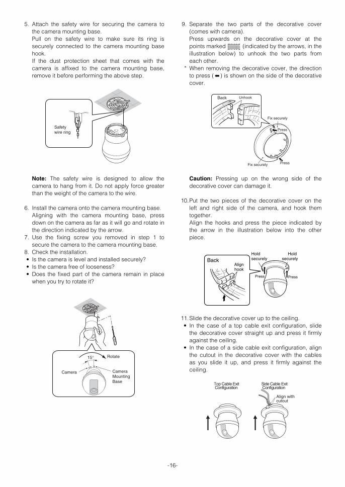
5. Attach the safety wire for securing the camera tothe camera mounting base. Pull on the safety wire to make sure its ring issecurely connected to the camera mounting basehook. If the dust protection sheet that comes with thecamera is affixed to the camera mounting base,remove it before performing the above step.
Note: The safety wire is designed to allow thecamera to hang from it. Do not apply force greaterthan the weight of the camera to the wire.
6. Install the camera onto the camera mounting base. Aligning with the camera mounting base, pressdown on the camera as far as it will go and rotate inthe direction indicated by the arrow.
7. Use the fixing screw you removed in step 1 tosecure the camera to the camera mounting base.
8. Check the installation. • Is the camera is level and installed securely?• Is the camera free of looseness? • Does the fixed part of the camera remain in place
when you try to rotate it?
9. Separate the two parts of the decorative cover(comes with camera). Press upwards on the decorative cover at thepoints marked (indicated by the arrows, in theillustration below) to unhook the two parts fromeach other.
* When removing the decorative cover, the directionto press ( ) is shown on the side of the decorativecover.
Caution: Pressing up on the wrong side of thedecorative cover can damage it.
10.Put the two pieces of the decorative cover on theleft and right side of the camera, and hook themtogether. Align the hooks and press the piece indicated bythe arrow in the illustration below into the otherpiece.
11.Slide the decorative cover up to the ceiling. • In the case of a top cable exit configuration, slide
the decorative cover straight up and press it firmlyagainst the ceiling.
• In the case of a side cable exit configuration, alignthe cutout in the decorative cover with the cablesas you slide it up, and press it firmly against theceiling.
➡
Safety wire ring
Camera Camera Mounting Base
Rotate15°
UnhookBack
Fix securely
Press
Fix securely Press
Press
Hold securelyBack
Hold securely
Align hook
Press
Top Cable Exit Configuration
Side Cable Exit Configuration
Align with cutout
WV-CS954_E 09.1.21 2:58 PM ページ16

-17-
UNINSTALLING THE CAMERA
Caution: Make sure you perform the steps belowcarefully and exactly when uninstalling the cameraand decorative cover. Failure to do so creates therisk of damage to the camera.
■ Removing the Decorative Cover Note that you need to separate the two parts of thedecorative cover in order to remove it. 1. Unhook the two parts of the decorative cover.
Press upwards on the decorative cover at thepoints marked (indicated by the arrows, in theillustration below) to unhook the two parts fromeach other.
* When removing the decorative cover, the directionto press ( ) is shown on the side of the decorativecover.
■ Uninstalling the Camera The camera and its base unit are secured by screws.This configuration provides double anchoring, and youshould use the following procedure to uninstall thecamera. 1. Remove the fixing screw that secures the camera to
the camera mounting base. Put the screw in a place where it will not becomelost.
2. Remove the camera from the camera mountingbase. Rotate the camera in the direction indicated by thearrow and remove it.
➡
UnhookBack
Fix securely
Press
Fix securely Press
3. Remove the safety wire from the camera mountingbase.
Camera Camera Mounting Base
Fixing screw
Rotate15°
After loosening the screw, press upwards on the camera and then remove it.
WV-CS954_E 09.1.21 2:58 PM ページ17
-18-
Pin no. Power source
1
2
3
4
24 V AC LIVE
24 V AC NEUTRAL
Ground
Not use
CONNECTIONS
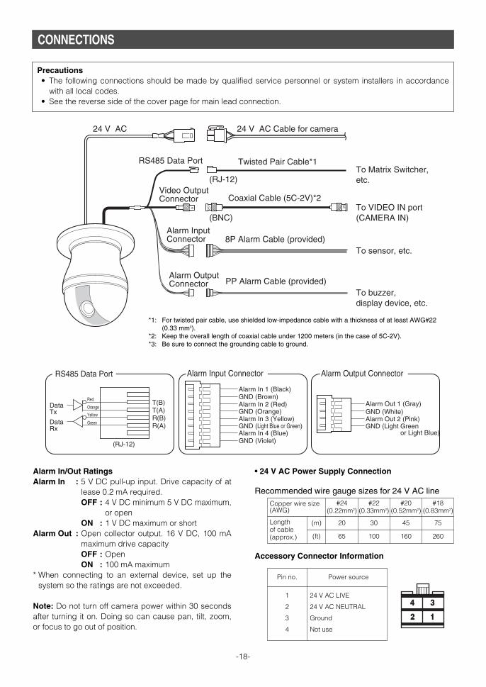
Coaxial Cable (5C-2V)*2
24 V AC 24 V AC Cable for camera
RS485 Data Port
To VIDEO IN port (CAMERA IN)
8P Alarm Cable (provided)
PP Alarm Cable (provided)
To sensor, etc.
To buzzer, display device, etc.
To Matrix Switcher, etc.
Video Output Connector
Alarm Input Connector
Alarm Output Connector
Twisted Pair Cable*1
(BNC)
(RJ-12)
RS485 Data Port Alarm Input Connector Alarm Output Connector
T(B)T(A)R(B)R(A)
Red
Orange
Yellow
Green
Data Tx
Data Rx
(RJ-12)
Alarm In 2 (Red)
Alarm In 1 (Black)GND (Brown)
Alarm In 3 (Yellow)
Alarm In 4 (Blue)
GND (Orange)
GND (Light Blue or Green)
GND (Violet)
Alarm Out 2 (Pink)
Alarm Out 1 (Gray)GND (White)
GND (Light Green or Light Blue)
*1: For twisted pair cable, use shielded low-impedance cable with a thickness of at least AWG#22(0.33 mm2).
*2: Keep the overall length of coaxial cable under 1200 meters (in the case of 5C-2V). *3: Be sure to connect the grounding cable to ground.
Alarm In/Out RatingsAlarm In : 5 V DC pull-up input. Drive capacity of at
lease 0.2 mA required. OFF : 4 V DC minimum 5 V DC maximum,
or open ON : 1 V DC maximum or short
Alarm Out : Open collector output. 16 V DC, 100 mAmaximum drive capacity OFF : OpenON : 100 mA maximum
* When connecting to an external device, set up thesystem so the ratings are not exceeded.
Note: Do not turn off camera power within 30 secondsafter turning it on. Doing so can cause pan, tilt, zoom,or focus to go out of position.
Precautions• The following connections should be made by qualified service personnel or system installers in accordance
with all local codes.• See the reverse side of the cover page for main lead connection.
#24(0.22mm2)
Copper wire size(AWG)
Lengthof cable(approx.)
(m)
(ft)
#22(0.33mm2)
#20(0.52mm2)
#18(0.83mm2)
20 30 45 75
65 100 160 260
• 24 V AC Power Supply Connection
Recommended wire gauge sizes for 24 V AC line
Accessory Connector Information
1
3
2
4
WV-CS954_E 09.1.21 2:58 PM ページ18

-19-
Contact InsertUp A
Approx.3 mm {0.1"}
Insert the wire until A positionand clamp the contacts.
Wire
Up
Contact
Wire
Approx.3 mm {0.1"}
Insert the wire until A positionand clamp the contacts.
Contact
Up Wire
How to Assemble the Cable with the AccessoryConnectorStrip back the cable jacket approx. 3 mm {0.1"} andseparate the individual conductors.
Prepare the individual conductors for clamping. UseMOLEX band tool part number 57027-5000 (for UL-Style Cable UL1015) or 57026-5000 (for UL-StyleUL1007) for clamping the contacts.After clamping the contacts, push them into the properholes in the accessory connector of this camera untilthey snap in place.
Cautions:• Shrinking the cable-entry seal is a one-time
procedure. Do not shrink the cable-entry seal untilascertaining that the unit is functioning.
• CONNECT THIS TO 24 V AC CLASS 2 POWERSUPPLY ONLY.
WV-CS954_E 09.1.21 2:58 PM ページ19

RS485 SETUP
The following procedure is to configure the RS485setup when using the system controller to control thecamera (pan, tilt, etc.) via the camera's data port.
1. Display the setup menu (page 24), move the cursorto COMMUNICATION O, and then press the CAM(SET) button. This will display the RS485 setup menu.
2. Check the unit number. (page 13)The UNIT NUMBER item shows the unit numberspecified by DIP Switch 1. The factory default unitnumber is 1. If DIP Switch 1 specifies 1 to 96 as the unit number,move the cursor to UNIT NUMBER and then tilt thejoystick left or right to select a unit number (1 to 96).
Note: It is not necessary to configure the RS485SET UP menu SUB ADDRESS setting.
3. Move the cursor to BAUD RATE, and then tilt thejoystick left or right to select a baud rate setting. Tilting the joystick cycles through the baud rate(transmission speed) display in the sequenceshown below. (unit: bits/s) The factory defaultsetting is 19200.
4. Move the cursor to DATA BIT, and then tilt thejoystick left or right to select a data bit setting (7 or8). The factory default setting is 8.
5. Move the cursor to PARITY CHECK, and then tilt thejoystick left or right to select a parity bit setting(NONE, ODD, EVEN). The factory default setting is NONE.
6. Move the cursor to STOP BIT, and then tilt thejoystick left or right to select a stop bit setting (1 or2). The factory default setting is 1.
7. Move the cursor to XON/XOFF, and then tilt thejoystick left or right to select an XON/XOFF setting. The factory default setting is NOT USE. NOT USE: Disables X ON/X OFF data flow control. USE : Enables X ON/X OFF data flow control.
8. Move the cursor to WAIT TIME, and then tilt thejoystick left or right to select a wait time setting. The wait time is the time that the camera shouldwait before resending data when no receiveacknowledgement (ACK) is returned after data issent. Tilting the joystick cycles through the wait timedisplay in the sequence shown below. (unit: ms)The factory default setting is OFF.
9. Move the cursor to ALARM DATA, and then tilt thejoystick left or right to select an alarm data sendmode setting. POLLING : Sends alarm data in response to a
request by the system controller. AUTO1 : Sends alarm data each time an alarm
signal is input. AUTO2 : Sends alarm data at five-second intervals.
This is the factory default setting. 10.Move the cursor to DELAY TIME, and then tilt the
joystick left or right to select a delay time setting.The delay time is the time is the time the camerashould wait before sending a receive acknowledge(ACK). The delay time display changes in thesequence shown below. (unit: ms) The factorydefault setting is OFF.
This setting can be configured only when 2-lineconfiguration is selected by DIP Switch 2. (page 12)
-20-
** RS485 SETUP ** UNIT NUMBERSUB ADDRESS BAUD RATEDATA BITPARITY CHECKSTOP BITXON/XOFFWAIT TIMEALARM DATADELAY TIME RET TOP
1-----192008NONE1NOT USEOFFAUTO2OFF
2400 4800 9600 19200
OFF ↔ 100MS ↔ 200MS ↔ 400MS ↔ 1000MS
OFF ↔ 100MS
WV-CS954_E 09.1.21 2:58 PM ページ20

USING THE SETUP MENU
This manual describe procedures for operating systemcontroller WV-CU650. All setting configuration procedures start from thesetup menu. This section explains how to display thesetup menu and provides details about the menu itemsthat it contains.
■ Displaying the Setup Menu
● When using the WV-CU650(1) Select the camera (this camera), and the
monitor where displays the setup menu. (2) Press the MENU button to display LCD MENU
CAM 101. (3) Press the ENTER button or CAM (SET) button to
display CAMERA SETUP. (4) Press the F1 button.
Refer to the pages below for details.
q CAMERA ID Camera ID SettingsPage 21
w SCENE SELECT Scene Select SettingsPage 22
e PRESET POSITION Preset Position SettingsPage 22
r LANGUAGE Language SettingPage 24
t ADVANCED SETUP Advanced Menu SettingsPage 24
■ Camera ID SettingsThe camera ID is a series of alphanumericcharacters that indicate the location of the camera.This item can be used to turn display of the cameraID on the monitor screen on or off, and to input thecamera ID.
1. Move the cursor to CAMERA ID, and then tilt thejoystick left or right to toggle camera ID display onand off.
2. Select ON or OFF, and then press the CAM (SET)button. The factory default setting is OFF.
3. Use the joystick to move the cursor the characteryou want to input, and then press the CAM (SET)button. This will cause the selected character to appear inthe camera ID input area. Repeat step 3 as manytimes as necessary to input all of the characters forthe camera ID. (Example: DOOR)To input a blank space Move the cursor to SPACE, and then press theCAM (SET) button. To delete all previously input charactersMove the cursor to RESET, and then press the CAM(SET) button. To change previously input charactersUse the joystick to move the cursor to the cameraID input area. Next, tilt the joystick left and right tomove the ↑ pointer to the character you want tochange. Finally, use step 3 above to input the newcharacter.
4. Move the cursor to POSI, and then press the CAM(SET) button. This will display the ID position setting menu.
5. Use the joystick to select a camera ID displayposition, and then press the MON (ESC) button. This registers the camera ID display position andreturns to the camera setting menu.
-21-
MODEL WV-CS954
CAMERA ID OFFSCENE SELECTPRESET POSITIONLANGUAGE
→ADVANCED SETUP
q
e
t
w
r
CAMERA ID--- 0123456789 ABCDEFGHIJKLM NOPQRSTUVWXYZ ().,'":;&#!?= +-*/%$
SPACE ---- POSI RET RESET
DOOR............
DOOR
Camera ID Input area
WV-CS954_E 09.1.21 2:58 PM ページ21

-22-
■ Scene Select SettingsDisplay the scene select setting menu from the setupmenu to configure scene select settings. First, displaythe scene select setting menu. 1. Display the setup menu (page 21), move the cursor
to SCENE SELECT O, and then press the CAM(SET) button. This will display the scene select setting menu.
● Scene Select SettingsUse the following procedure to configure scene selectsettings. 1. Move the cursor to SCENE, and then tilt the joystick
left or right to change the scene setup.INDOOR (L) : Indoor setting (picture quality
priority)INDOOR (H) : Indoor setting (sensitivity
priority)OUTDOOR (L) : Outdoor setting (picture
quality priority) OUTDOOR (H) : Outdoor setting (sensitivity
priority)
Settings related to the picture switch depending onthe scene settings. Scene select settings andrelationship to other settings are shown in the tablebelow.
2. Move the cursor to LOAD, and then press the CAM(SET) button. This will cause the setup you selected for SCENE instep 1 to be applied to the image.
■ Preset Position Settings● Position Number Selection (MAP) You could use the MAP item on the pan/tilt setup menuinstead of the PRESET item to select a position number. 1. Move the cursor to PRESET POSITION O, and then
press the CAM (SET) button.
2. Move the cursor to the number you want to select,and then press the CAM (SET) button. This registers the position number setting anddisplays the preset setting menu. (this page) To select a position number in the range of 033 to064, move the cursor to 33-64 in the lower left cornerof the menu, and then press the CAM (SET) button.Preset numbers set subsequently are the same.
Notes:• An asterisk (*) to the right of a position number
indicates that it already has a preset positionassigned to it. The home position number is indicated by theletter H next to the asterisk.
• When the cursor is located at a position numberthat has a position ID, the position ID textappears next to ID: on the menu screen.
● Position Setting (POSITION SET) The position setting can be used to specify the cameraposition (pan and tilt), the lens zoom setting, and thefocus setting. 1. Move the cursor to POSITION SET O and press the
CAM (SET) button to display the position setting menu.
**SCENE SELECT**
SCENE INDOOR(L)
LOAD RET TOP
AGC SENS UP SHUTTER
INDOOR (L) MID OFF OFF
INDOOR (H) HIGH ×2 AUTO OFF
OUTDOOR (L) MID OFF AUTO
OUTDOOR (H) HIGH ×2 AUTO AUTO
BW DNR WHITE BAL
INDOOR (L) OFF LOW ATW1
INDOOR (H) OFF HIGH ATW1
OUTDOOR (L) AUTO LOW ATW2
OUTDOOR (H) AUTO HIGH ATW2
**PRESET POSITION** 2 6 10 14 18 22 26 30
1* 5 9 13 17 21 25 29 ID:DOOR033-064 225-256RET TOP
3 7 11 15 19 23 27 31
4 8 12 16 20 24 28 32
**PRESET POSITION** 34 38 42 46 50 54 58 62
33 37 41 45 49 53 57 61 ID:065-096 001-032RET TOP
35 39 43 47 51 55 59 63
36 40 44 48 52 56 60 64
PRESET NO. 1*POSITION SETPRESET ID
RET TOP DEL
ON
WV-CS954_E 09.1.21 2:58 PM ページ22
-23-
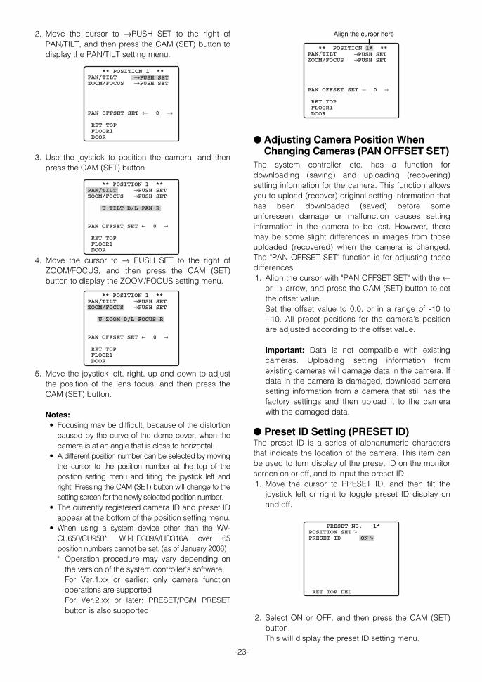
2. Move the cursor to →PUSH SET to the right ofPAN/TILT, and then press the CAM (SET) button todisplay the PAN/TILT setting menu.
3. Use the joystick to position the camera, and thenpress the CAM (SET) button.
4. Move the cursor to → PUSH SET to the right ofZOOM/FOCUS, and then press the CAM (SET)button to display the ZOOM/FOCUS setting menu.
5. Move the joystick left, right, up and down to adjustthe position of the lens focus, and then press theCAM (SET) button.
Notes:• Focusing may be difficult, because of the distortion
caused by the curve of the dome cover, when thecamera is at an angle that is close to horizontal.
• A different position number can be selected by movingthe cursor to the position number at the top of theposition setting menu and tilting the joystick left andright. Pressing the CAM (SET) button will change to thesetting screen for the newly selected position number.
• The currently registered camera ID and preset IDappear at the bottom of the position setting menu.
• When using a system device other than the WV-CU650/CU950*, WJ-HD309A/HD316A over 65position numbers cannot be set. (as of January 2006) * Operation procedure may vary depending on
the version of the system controller's software. For Ver.1.xx or earlier: only camera functionoperations are supportedFor Ver.2.xx or later: PRESET/PGM PRESETbutton is also supported
● Adjusting Camera Position WhenChanging Cameras (PAN OFFSET SET)
The system controller etc. has a function fordownloading (saving) and uploading (recovering)setting information for the camera. This function allowsyou to upload (recover) original setting information thathas been downloaded (saved) before someunforeseen damage or malfunction causes settinginformation in the camera to be lost. However, theremay be some slight differences in images from thoseuploaded (recovered) when the camera is changed.The "PAN OFFSET SET" function is for adjusting thesedifferences. 1. Align the cursor with "PAN OFFSET SET" with the ←
or → arrow, and press the CAM (SET) button to setthe offset value.Set the offset value to 0.0, or in a range of -10 to+10. All preset positions for the camera's positionare adjusted according to the offset value.
Important: Data is not compatible with existingcameras. Uploading setting information fromexisting cameras will damage data in the camera. Ifdata in the camera is damaged, download camerasetting information from a camera that still has thefactory settings and then upload it to the camerawith the damaged data.
● Preset ID Setting (PRESET ID) The preset ID is a series of alphanumeric charactersthat indicate the location of the camera. This item canbe used to turn display of the preset ID on the monitorscreen on or off, and to input the preset ID. 1. Move the cursor to PRESET ID, and then tilt the
joystick left or right to toggle preset ID display onand off.
2. Select ON or OFF, and then press the CAM (SET)button. This will display the preset ID setting menu.
→PUSH SET
** POSITION 1 **PAN/TILTZOOM/FOCUS
PAN OFFSET SET ← 0 →
RET TOP FLOOR1 DOOR
→PUSH SET
→PUSH SET→PUSH SET
** POSITION 1 **PAN/TILTZOOM/FOCUS
U TILT D/L PAN R
PAN OFFSET SET ← 0 →
RET TOP FLOOR1 DOOR
PRESET NO. 1*POSITION SETPRESET ID
RET TOP DEL
ON
→PUSH SET →PUSH SET
** POSITION 1* **PAN/TILTZOOM/FOCUS
PAN OFFSET SET ← 0 →
RET TOP FLOOR1 DOOR
Align the cursor here
→PUSH SET→PUSH SET
** POSITION 1 **PAN/TILTZOOM/FOCUS
U ZOOM D/L FOCUS R
PAN OFFSET SET ← 0 →
RET TOP FLOOR1 DOOR
WV-CS954_E 09.1.21 2:58 PM ページ23

-24-
3. Use the joystick to move the cursor the character youwant to input, and then press the CAM (SET) button. The text input procedure is the same as that forcamera ID input. See steps 3 through 5 under “Camera ID Settings”on page 21 for information about inputting the textfor the preset ID and specifying its position on thedisplay.
To copy the preset ID of another position number Move the cursor to COPY, and then press the CAM(SET) button. This displays the preset ID of theposition number preceding the one you arecurrently configuring. Each press of the CAM (SET)button scrolls back to the next sequential positionnumber and displays its preset ID.
■ Language Setting1. Move the cursor to LANGUAGE O, and then press
the CAM (SET) button. 2. On the 8-language selection menu that appears,
select the language you want to use. The factory default setting is English.
* All of the example screens in these OperatingInstructions show English display messages.
3. Move the cursor to SET, and then press the CAM(SET) button. When you switch the languages, the password andtitles are deleted.
* The item that was set flashes when the language isbeing changed and stops flashing when thelanguage has been changed. Do not operate thesystem controller when changing settings.
* If you have selected either Japanese or Chinese asthe language, only the IDs and titles can be set inkatakana or Chinese.
* The “LANGUAGE” display remains in English evenwhen the language setting is changed.
■ Advanced Menu SettingsThe advanced setup menu can be displayed from thesetup menu. 1. Display the setup menu (page 21), move the cursor
to → ADVANCED SETUP, and then press the CAM(SET) button. This will display the advanced setup menu.
All items can be set on the advanced setup menu. To switch back to the quick setup menu from thedetailed menu, move the cursor to →QUICK SETUP, and then press the CAM (SET) button.
Refer to the pages below for details of setup menuitems.
q CAMERA Camera Settings Page 25w PAN/TILT Pan/Tilt Settings Page 30e ALARM Alarm Settings Page 38r SPECIAL Special Settings Page 41t COMMUNICATION* Communication Settings
Page 20y SCENE SELECT Scene Select Settings
Page 22u LANGUAGE Language Setting
This pagei QUICK SETUP Quick Menu Settings
Page 21o PASSWORD LOCK Password Settings
Page 44
* This item appears only when RS485 settings areconfigured with the DIP switches.
PRESET NO. 1* 0123456789 ABCDEFGHIJKLM NOPQRSTUVWXYZ ().,'":;&#!?= +-*/%$
SPACE COPY POSI RET RESET
DOOR............
MODEL WV-CS954CAMERAPAN/TILTALARMSPECIALCOMMUNICATIONSCENE SELECTLANGUAGE
→QUICK SETUPPASSWORD LOCK OFF
q
e
t
u
o
w
r
y
i
WV-CS954_E 09.1.21 2:58 PM ページ24
CAMERA SETTINGS
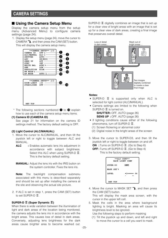
■ Using the Camera Setup Menu Display the camera setup menu from the setupmenu (Advanced Menu) to configure camerasettings (page 24). 1. Display the setup menu (page 24), move the cursor to
CAMERA O, and then press the CAM (SET) button. This will display the camera setup menu.
* The following sections numbered q to !3 explainhow to use each of the camera setup menu items.
(1) Camera ID (CAMERA ID)See page 21 for information on the camera IDsettings method. The factory default setting is OFF.
(2) Light Control (ALC/MANUAL) 1. Move the cursor to ALC/MANUAL, and then tilt the
joystick left or right to toggle between ALC andMANUAL. ALC : Enables automatic lens iris adjustment in
accordance with subject brightness.Select this ALC when using SUPER-D 3.This is the factory default setting.
MANUAL: Adjust the lens iris with the IRIS button onthe system controller. Fixes the lens iris.
Note: The backlight compensation submenuassociated with this menu is described separatelyand should be set up after installing the camera atthe site and observing the actual site picture.
2. If ALC is set in step 1, press the CAM (SET) buttonto set SUPER-D 3.
SUPER-D 33 (Super Dynamic 33) When there is wide variation between the illumination oflight and dark areas of the location being monitored,the camera adjusts the lens iris in accordance with thebright areas. This causes loss of detail in dark areas.Conversely, adjusting lens brightness for the darkareas cause brighter area to become washed out.
SUPER-D 3 digitally combines an image that is set upfor a clear view of bright areas with an image that is setup for a clear view of dark areas, creating a final imagethat preserves overall detail.
Notes:• SUPER-D 3 is supported only when ALC is
selected for light control (ALC/MANUAL). • Camera settings are limited to the following when
SUPER-D 3 is turned on. SHUTTER: OFF, AUTO (page 26) SENS UP : OFF, AUTO (page 26)
• If lighting conditions cause either of the followingphenomena, turn off SUPER-D 3. (1) Screen flickering or abnormal color(2) Digital noise in the bright areas of the screen
3. Move the cursor to SUPER-D3, and then tilt thejoystick left or right to toggle between on and off. ON : Turns on SUPER-D 3. (Go to Step 6) OFF : Turns off SUPER-D 3. (Go to Step 4)
This is the factory default setting.
4. Move the cursor to MASK SET O, and then pressthe CAM (SET) button. This will display the mask area screen, with thecursor in the upper left cell.
5. Mask the cells in the area where backgroundlighting is bright. Masking an area will cause itsbrightness level to be ignored. Use the following steps to perform masking (1) Tilt the joystick up and down, and left and right
to move the cursor to a cell you want to mask.
-25-
**CAMERA SETUP** 1/2CAMERA ID OFFALC/MANUAL ALCSHUTTER AUTOAGC ON(MID)SENS UP OFFSYNC INTWHITE BAL ATW1DNR LOWRESOLUTION HIGHBW MODEAF MODE AUTO L
q
e
t
u
o
!1
w
r
y
i
!0
**CAMERA SETUP** 2/2ZOOM LIMIT ×30STABILIZER OFF
RET TOP
!2!3
Loss of detail in dark areas...
Wash out of bright areas ...
Two images digitally combined to create a clear final image
**ALC CONT** BACK LIGHT COMP
SUPER-D3
MASK SET
LEVEL
RET TOP
OFF
•I••••• 64- +
WV-CS954_E 09.1.21 2:58 PM ページ25

-26-
(2) Press the CAM (SET) button to mask the cell. Moving the cursor to a cell that is alreadymasked causes the blinking pattern of thecursor to alternate between horizontal stripesand white. Pressing the CAM (SET) button while the cursoris located at a masked cell cancels the maskingof the cell. To cancel all masking areas, press the F3button.
(3) After masking all of the cells you want, press theMON (ESC) button to return to the ALC CONTmenu in step 1.
6. Move the cursor to LEVEL, and then tilt the joystickleft and right to adjust the picture output level(picture contrast). If you selected ON in step 3 of this procedure, bestresults can be obtained by setting a contrast levelthat is somewhat high. A contrast level that is toohigh, however, may increase the tendency ofafterimages and noise.
Note: If operation of the system controller's IRIS(OPEN, CLOSE) button during operation is doneafter the menu is closed, the LEVEL on theCAMERA menu is reflected and stored for thesesettings. However, if the camera is in a presetposition, it is reflected as a parameter of the presetposition. To return to the initial factory default level,execute the system controller's iris reset.
(3) Shutter Speed (SHUTTER) 1. Move the cursor to SHUTTER, and then tilt the
joystick left or right to select a shutter speedsetting. Tilting the joystick cycles through the shutter speedsettings display in the sequence shown below.(unit: sec)
When SUPER-D 33 is turned off
When SUPER-D 33 is turned on
AUTO: This setting, by moving the shutterautomatically when necessary, provides aclearer picture of extremely bright objectsoutdoors, etc. This is the factory defaultsetting.
OFF : Fixed at 1/60 seconds.
Notes:• When AUTO is selected for the shutter setting,
fluorescent lighting may cause flickering of thepicture. If this happens, select OFF or 1/100 forthe shutter speed setting.
• AUTO is disabled when MANUAL is selected forlight control (ALC/MANUAL) and FIX is selectedfor electronic sensitivity enhancement (SENS UP).
(4) Gain Control (AGC)1. Move the cursor to AGC, and then tilt the joystick
left or right to select a gain control setting. ON (LOW) : Low gainON (MID) : Medium gain. This is the factory default
setting.ON (HIGH) : High gainOFF : Fixed gain
Note: When AGC is turned on, the noise reductionfunction automatically activates under low illuminationto reduce digital noise. This also, however, can causeafterimages to be generated by moving objects, andby panning and tilting the camera. For moreinformation, see the DNR setting (page 28).
(5) Electronic Sensitivity Enhancement (SENS UP) 1. Move the cursor to SENS UP, and then tilt the
joystick left or right to select an electronic sensitivityenhancement setting. The electronic sensitivity enhancement setting canbe changed only when OFF or AUTO is selected forthe shutter speed (SHUTTER) setting. Tilting thejoystick cycles through the settings display in thesequence shown below. The factory default settingis OFF.
When SUPER-D 33 is turned off
When SUPER-D 33 is turned on
Note: The following are the differences betweenAUTO and FIX.
AUTO: Selecting X32 AUTO, for example,automatically increases sensitivity, up toa maximum of 32 times.
FIX : Selecting X32 FIX, for example,increases sensitivity 32 times.
The FIX settings cannot be selected when theshutter speed (SHUTTER) setting is 1/100.
Caution: Turning on SENS UP can cause digital noiseand white spots (blemish) to appear in the picture.
OFF ↔ AUTO ↔ 1/100 ↔ 1/250 ↔ 1/500 ↔ 1/1000
1/10000 ↔ 1/4000 ↔ 1/2000
OFF ↔ AUTO
OFF ↔ X2 AUTO ↔ X4 AUTO ↔ X6 AUTO ↔ X10 AUTO ↔ X16 AUTO
X16 FIX ↔ X10 FIX ↔ X6 FIX ↔ X4 FIX ↔ X2 FIX ↔ OFF
X32 FIX X32 AUTO
↔↔
↔↔
OFF ↔ X2 AUTO ↔ X4 AUTO ↔ X6 AUTO
X32 AUTO ↔ X16 AUTO ↔ X10 AUTO
WV-CS954_E 09.1.21 2:58 PM ページ26

-27-
(6) Synchronization (SYNC)This camera supports the following three sync modes,which are listed in priority sequence from highestpriority to lowest.
(1) Multiplexed vertical drive (VD2) (2) Internal sync (INT)(3) Line-lock (LL)
Input of a multiplexed vertical driver (VD2) signalautomatically switches to VD2 sync, regardless of thecamera's current sync mode (SYNC). In this case, thecamera setting menu shows EXT (VD2) for the SYNCsetting, which cannot be changed to internal sync(INT) or line-lock (LL). The following procedures explain how to select internalsync (INT) and line-lock (LL), and how to performphase adjustment when line-lock (LL) is selected. 1. Move the cursor to SYNC, and then tilt the joystick
left or right to select the sync mode. INT : Internal sync. This is the factory default setting.LL : Line-lock (Cannot be used in areas with 50 Hz
power.) Selecting LL and pressing the CAM (SET) buttonwill display the SYNC setting menu, which can beused for configuring detailed settings. (This page)
● Adjusting the Phase for Line-lockSynchronization
Connect the video output signal of the camera beingadjusted and the reference video output signal to atwo-input oscilloscope.Set the oscilloscope to the vertical rate, and thenexpand the vertical sync portion on the oscilloscope. 1. Move the cursor to COARSE, and then tilt the
joystick left or right to align the coarse adjustmentof the vertical phases of the camera being adjustedwith that of the reference camera. Coarse adjustment be performed across 16 steps(1 through 16). Adjusting past step 16 returns tostep 1.
2. Move the cursor to FINE, and then tilt the joystickleft or right to align the fine adjustment of thevertical phases of the camera being adjusted withthat of the reference camera.
Notes:• To reset COARSE and FINE to the preset values,
press the F3 button. For WV-RM70, press theright and left switches simultaneously. COARSEis preset to zero-crossing of the AC line phase.
• If the AC line phase contains spike noise, etc.,the vertical phase of the video output signal maybe disturbed.
(7) White Balance (WHITE BAL)1. Move the cursor to WHITE BAL, and then tilt the
joystick left or right to select a white balance mode. (1) Auto-Tracing White Balance Mode (ATW1/ATW2)
In this mode, the camera continually monitorsthe color temperature of the light source andautomatically adjusts white balance. The following are the approximate supportedcolor temperature ranges in this mode. ATW1: 2,700 K to 6,000 K. This is the factory
default setting.ATW2: 2,000 K to 6,000 K (Mode recommended
for sodium lighting)Proper white balance may not be possible underthe following conditions. In such cases, use theAWC while balance mode.
• When the subject contains mostly dark colors • When the light source is a deep blue sky or
twilight • When illumination of the subject is low
(2) Auto-Tracing White Balance Control (AWC) In this mode, the supported color temperaturerange is approximately 2,000 K to 10,000 K. Thismode is best in locations where the light sourceis constant.
(a) To select AWC, tilt the joystick left and selectAWC→PUSH SET.
(b) Press the CAM (SET) button to start whitebalance adjustment. PUSH SET is highlightedon the display while white balance adjustment isbeing performed.
• PUSH SET becomes unhighlighted again whenwhite balance adjustment is complete. Tilt thejoystick right to display AWC.
• If white balance adjustment cannot be completedfor some reason, PUSH SET will remainhighlighted on the display. If this happens, it couldmean that the color temperature is outside thesupported range, or that illumination is too low.
2. Select ATW1, ATW2, and AWC, then press the CAM(SET) button, either the ATW setting menu or theAWC setting menu appears, and you can fine tunethe white balance. Move the cursor to R or B, and then tilt the joystick leftor right to fine tune the level. The R is red and the B isblue, moving in the + direction makes the colorsdarker, moving in the - direction makes them lighter.
** SYNC **
V PHASE
COARSE
FINE
RET TOP
1(1--16)
••I•••• 96- +
WV-CS954_E 09.1.21 2:58 PM ページ27

-28-
Note: White balance is adjusted in accordance withon-screen color temperature, which the cameradetects automatically. Correct adjustment may notbe possible if a strong light source is shining on thescreen.
(8) Digital Noise Reduction (DNR) 1. Move the cursor to DNR, and then tilt the joystick
left or right to select a digital noise reduction (DNR)setting. LOW : Low DNR, Low afterimage. This is the factory
default setting.HIGH : High DNR, High afterimage
(9) Resolution (RESOLUTION) 1. Move the cursor to RESOLUTION, and then tilt the
joystick left or right to select NORMAL or HIGH.NORMAL: Sets horizontal resolution to a minimum
of 480 TV lines. (In color mode)HIGH : Sets horizontal resolution to a minimum
of 520 TV lines. (In color mode) This isthe factory default setting.
(10) Black and White Mode (BW MODE)Moving the cursor to BW MODE and pressing the CAM(SET) button displays a BW MODE setting menu. Use the BW MODE setting menu to configure blackand white mode settings. 1. Move the cursor to BW, and then tilt the joystick left
or right to select a black and white control setting. AUTO : The camera automatically switches
between the color mode and the black andwhite mode in accordance with picturebrightness (illuminance). The black and white mode is selectedwhen lighting is low, while the color mode isselected for bright lighting.
ON : Selects the black and white mode. OFF : Selects the color mode. This is the factory
default setting.
Note: The above setting cannot be configuredwhen BW is selected for the ALARM IN 4 setting(page 40).
2. If you selected AUTO in step 1, move the cursor toLEVEL and then tilt the joystick left to select thethreshold illuminance level for switching betweenthe color mode and the black and white mode.The illuminance shown below is based on theassumption that the camera is used in an area lit byhalogen lamps, and that AGC on the menu is set toMID. LOW : Switches to the black and white mode when
illuminance around the camera isapproximately 1.5 lux{fc} or lower (whenAGC ON (MID), SENS UP OFF is set).
HIGH : Switches to the black and white mode whenilluminance around the camera isapproximately 3 lux{fc} or lower (when AGCON (MID), SENS UP OFF is set). This is thefactory default setting.
Note: When near-infrared lamps are used, theimage may be displayed out of focus and modeswitching may not perform automatically.
3. If you selected AUTO in step 1, move the cursor toDURATION TIME and then tilt the joystick left toselect the time the camera should wait beforeswitching between the color mode and the blackand white mode after there is a change in theilluminance level. Available Settings: 10 s - 30 s - 60 s - 300 s
(S) (L)Note: When AUTO is selected, switching betweenthe color mode and the black and white mode is notperformed while pan, tilt, zoom, or focus is beingperformed.
4. Move the cursor to BURST (BW), and then tilt thejoystick left or right to turn burst signal output on oroff. This setting is for black and white mode display. ON: Turns on burst signal output. This is the
factory default setting.OFF: Turns off burst signal output.
Note: With some monitors and VCR models, outputof a camera images in the black and white modewill not display a proper image unless a burst signalis provided. Select ON for this setting when usingequipment that requires a burst signal.
** BW MODE **
BW LEVEL DURATION TIME
BURST(BW)
RET TOP
AUTOHIGH•I••S L
ON
** ATW1 **
R
B
RET TOP
•••I•••129- +
•••I•••127- +
WV-CS954_E 09.1.21 2:58 PM ページ28
-29-
(11) Auto Focus (AF MODE)1. Move the cursor to AF MODE, and then tilt the
joystick left or right to select an auto-focus modesetting.MANUAL S.M.L : Activates auto-focus when the AF
button on the system controller ispressed.
AUTO S.M.L : Auto focus is used automaticallywhen PAN, TILT or ZOOM areused in manual operation.
The letters S (Small), M (Medium), and L (Large)indicate the size of the auto-focus sensing area. The factory default setting is AUTO L.
Notes:• The AUTO (S.M.L.) setting can be selected only
when OFF, x2 FIX or x2 AUTO is selected for theelectronic sensitivity enhancement (SENS UP).Any other SENS UP setting causes MANUAL(S.M.L.) to be selected automatically for theauto-focus mode (AUTO).
• Zooming up from WIDE can cause the image togo out of focus.
• Auto-focus may not be possible with the types ofobjects listed below. For such objects, focusmanually.
Example:• Shiny or high intensity objects• Objects shot through wet or dirty glass • Pictures that are a mixture of distant and nearby
objects • White walls and other single-color objects• Venetian blinds and other vertically striped
objects • Slanted objects• Objects illuminated with low lighting
Auto-focus focuses on the object in the center ofthe picture, so objects around the outside peripheryof the picture will not be in focus.
(12) Zoom Limit (ZOOM LIMIT) 1. Move the cursor to ZOOM LIMIT, and then tilt the
joystick left or right to select a zoom limit setting. When doing manual operation, zoom operationcannot go beyond the zoom limit.Optical zoom ranges from 1 to 30 magnifications,while digital zoom is used for higher magnifications(up to 300). The factory default setting is x30 (30x opticalzoom).
Notes:• If zoom limit is set to more than 30x, then zoom
operation pauses at 30x magnification. • Increasing the zoom to over 30x magnification
(digital zoom) decreases the resolution. • You cannot set a zoom magnification of greater
than 30x as a preset position.
(13) Auto Image Stabilizer (STABILIZER)This function electronically compensates for anunstable camera image due to movement of amounting pole or bracket. 1. Move the cursor to STABILIZER, and then tilt the
joystick left or right to turn the stabilizer on or off.The default setting is OFFON : Automatically compensates for an unstable
image.OFF : Image stabilizer will not operate. This is the
factory default setting.
Notes:• The stabilizer may not be effective for the
following subjects. Example: • Objects illuminated with low lighting
• Single-color objects (white walls etc)• Fast moving periodic action, such as
mechanical vibration, may not be tracked.• The stabilizer does not work during
PAN/TILT/ZOOM/FOCUS or when the camerasetup menu is open.
• When set to ON, some effective pixels on theedge of the CCD are used by the stabilizationfunction. This may result in a small reduction inresolution and a narrower angle of view. Afteractivating the image stabilizer function, checkthat the field of view is correct.
• Image stabilization may not function where thereis excessive camera movement or when thescene is low light or low contrast objects.
WV-CS954_E 09.1.21 2:58 PM ページ29

PAN/TILT SETTINGS
■ Using the Pan/Tilt Setup Menu Display the pan/tilt setup menu from the setup menu toconfigure pan and tilt settings. First, display the pan/tilt setup menu. 1. Display the setup menu (page 24), move the cursor to
PAN/TILT O, and then press the CAM (SET) button.This will display the pan/tilt setup menu.
* The following sections numbered q to !4 explainhow to use each of the pan/tilt setup menu items.
(1) Position Number Selection (PRESET)Positions can be assigned numbers, each of which canbe configured with a monitoring position andmonitoring conditions. You can use either the PRESET item or the MAP item onthe pan/tilt setup menu to select a position number. Position numbers 1 through 4 are used for alarmfunctions (pages 39 and 40) and operating them. 1. Move the cursor to the 1 next to the PRESET item,
and then tilt the joystick left or right to change theposition number to the one you want.
2. Press the CAM (SET) button. This registers the position number setting anddisplays the preset setting menu.
(2) Position Number Selection (MAP) You could use the MAP item on the pan/tilt setup menuinstead of the PRESET item to select a position number. 1. Move the cursor to MAP O, and then press the
CAM (SET) button.
2. Move the cursor to the number you want to select,and then press the CAM (SET) button. This registers the position number setting anddisplays the preset setting menu. (this page) To select a position number in the range of 033 to064, move the cursor to 33-64 in the lower left cornerof the menu, and then press the CAM (SET) button.Preset numbers set subsequently are the same.
Notes:• An asterisk (*) to the right of a position number
indicates that it already has a preset positionassigned to it. The home position number is indicated by theletter H next to the asterisk.
• When the cursor is located at a position numberthat has a position ID, the position ID textappears next to ID: on the menu screen.
● Position Setting (POSITION SET) See pages 22 and 23 for information on the settingmethod.
● Adjusting Camera Position WhenChanging Cameras (PAN OFFSET SET)
See page 23 for information on the setting method.
● Preset ID Setting (PRESET ID) See pages 23 and 24 for information on the settingmethod.
● Light Control (ALC/MANUAL) See pages 25 and 26 for information on the settingmethod.You can adjust the lens iris setting on the detailedmenu when MANUAL is set.
-30-
**PAN/TILT SETUP**1/2PRESET 1MAPHOME POSITION OFFSELF RETURN OFFAUTO MODE OFFAUTOPAN KEY AUTO PANPATROLPRIVACY ZONE OFFIMAGE HOLD OFFDIGITAL FLIP ONPROPO.P/T ON
q
e
t
u
o
!1
w
r
y
i
!0
**PAN/TILT SETUP**2/2AREA TITLE ON(USER)TILT ANGLE 0°CLEANING OFF
RET TOP
!2!3
!4
**PRESET POSITION** 2 6 10 14 18 22 26 30
1* 5 9 13 17 21 25 29 ID:DOOR033-064 225-256RET TOP
3 7 11 15 19 23 27 31
4 8 12 16 20 24 28 32
**PRESET POSITION** 34 38 42 46 50 54 58 62
33 37 41 45 49 53 57 61 ID:065-096 001-032RET TOP
35 39 43 47 51 55 59 63
36 40 44 48 52 56 60 64
PRESET NO. 1*POSITION SETPRESET IDALC/MANUALAF MODEDWELL TIMESCENE FILEPRESET SPEED
RET TOP DEL
ON ALC MANUAL L10SOFF ••••••I255L H
WV-CS954_E 09.1.21 2:58 PM ページ30

● Auto Focus (AF MODE)1. Move the cursor to AF MODE, and then tilt the joystick
left or right to select an auto-focus function setting.MANUAL S.M.L : Auto focus does not operate
after moving to a preset position. AUTO S.M.L : Auto focus operates after
moving to a preset position.
● Sequence/Sort DWELL Time (DWELL TIME)
This section explains how to set the length of time thecamera stops (time it stops rotating) and tapes thescene while in the various preset positions for thesequence and sort operations (page 32). 1. Move the cursor to DWELL TIME, and then tilt the
joystick left or right to select a DWELL time setting. Tilting the joystick cycles through the stop timedisplay in the sequence shown below. (unit: sec, min)
● Scene File Setting (SCENE FILE) Up to 10 scene files, each of which contains camerasettings for a specific location (scene), can be storedin memory. Scene files are managed using scene filenumbers from 1 through 10, and can be selected whenconfiguring preset position settings. The following procedures explain how to select ascene file and how to configure scene file settings.
(1) Selecting a Scene File Use this procedure when you want to apply thesettings of a previously stored scene file when you areconfiguring the settings of a preset position. 1. Move the cursor to SCENE FILE, and then tilt it left
and right to select the number of the scene file youwant to select.
(2) Configuring Scene File Settings1. Move the cursor to SCENE FILE, and then tilt it left
and right to select the number of the scene filewhose settings you want to configure.
2. Press the CAM (SET) button. This will display the scene file setting menu.The following items can be set on the Scene filesettings menu. See camera settings for details oneach setting. • SHUTTER (page 26)• AGC (page 26)• SENS UP (page 26) • WHITE BAL (pages 27, 28)• MOTION DET (page 38)
● Preset Speed Setting (PRESET SPEED)Set the speed the camera moves to the various presetpositions for the sequence and sort operations (page32). 1. Move the cursor to PRESET SPEED, and then tilt the
joystick left or right to change the speed setting. Shifting the setting towards the L side decreases thespeed, while shifting towards the H side increase it.
● Deleting a Preset Position (DEL) 1. Move the cursor to DEL, and then press the CAM
(SET) button. This deletes the contents of the currently selectedposition number and displays the position selectionmenu.
-31-
2S ↔ 3S ↔ 5S ↔ 10S ↔ 30S ↔ 1MIN
4MIN ↔ 3MIN ↔ 2MIN
PRESET NO. 1*POSITION SETPRESET IDALC/MANUALAF MODEDWELL TIMESCENE FILEPRESET SPEED
RET TOP DEL
ON ALC MANUAL L10SOFF ••••••I255L H
PRESET NO. 1*POSITION SETPRESET IDALC/MANUALAF MODEDWELL TIMESCENE FILEPRESET SPEED
RET TOP DEL
ON ALC MANUAL L10S1 ••••••I255L H
**SCENE FILE 1**SHUTTERAGCSENS UPWHITE BALMOTION DET
RET TOP
OFFON(MID) OFFATW1OFF
PRESET NO. 1*POSITION SETPRESET IDALC/MANUALAF MODEDWELL TIMESCENE FILEPRESET SPEED
RET TOP DEL
ON ALC MANUAL L10SOFF ••••••I255L H
PRESET NO. 1*POSITION SETPRESET IDALC/MANUALAF MODEDWELL TIMESCENE FILEPRESET SPEED
RET TOP DEL
ON ALC MANUAL L10SOFF ••••••I255L H
**PRESET POSITION** 2* 6* 10* 14* 18* 22* 26* 30*
3* 7* 11* 15* 19* 23* 27* 31*
4* 8* 12* 16* 20* 24* 28* 32*
1 5* 9* 13* 17* 21* 25* 29* ID:DOOR033-064 225-256RET TOP
WV-CS954_E 09.1.21 2:58 PM ページ31

Notes:• The HOME setting should be selected when you
want to normally leave the camera in the homeposition and occasionally perform pan and tilt,or when you want to activate SEQ.
• PATR1-4 displays only the set number of patrolroutines (page 34).
(5) Auto Mode Setting (AUTO MODE) Use the auto mode setting to specify the cameramovement mode (OFF, SEQ, SORT, AUTO PAN,PATROL 1~4, AUTO TRACK). After selecting AUTO PAN, you can use the AUTO PANsetting menu to configure detailed settings. 1. Move the cursor to AUTO MODE, and then tilt the
joystick left or right to select a camera movementmode setting.OFF : Manual movement only SEQ : Sequentially switches between preset
positions in position number sequence.(sequential movement)
SORT : Sequentially switches between presetpositions counterclockwise, starting fromthe camera home position. (sort movement)
AUTO PAN:Camera pans automatically within the rangespecified by PAN. Selecting AUTO PAN andpressing the CAM (SET) button will display theAUTO PAN setting menu, which can be usedfor configuring detailed settings. (page 33)
PATROL 1 to 4:Operates the camera in accordancewith patrol function settings.
AUTO TRACK:Auto tracking is done for movingobjects under the following conditions. The moving object must be larger than oneof the screen blocks (1/48 of screen area),it must have 5 % comparative contrast withthe background image.
Notes:• Automatic tracking covers a range from
horizontal to directly below the camera. Thedigital flip function (page 36) does not operate.Also, the pan range can be limited by using thePAN LIMIT setting (page 33).
• The automatic tracking function incorporated inthis system easily tracks moving objects onscreen. Moving subjects are not automaticallytracked in the following situations. • When multiple moving subjects are on screen• When the subjects are moving very fast• When the subject has little contrast• When moving objects are either large or small• When the image is dark• When the image flickers
Tilting the joystick cycles through settings in thesequence shown below.
(3) Home Position Setting (HOME POSITION)A currently configured preset position can bedesignated as the home position. Pressing the HOME button of the system controller willcause the camera to move to the currently specifiedhome position. Use the following procedure to make apreset position the home position. 1. Move the cursor to HOME POSITION, and then tilt
the joystick left or right to select the positionnumber of the preset position you want to make thehome position. This causes the preset position whose positionnumber you select to become the home position. Ifyou do not want to use the home position function,select OFF for the HOME POSITION setting.
(4) Self Return Setting (SELF RETURN) The self return setting can be used to specify automaticreturn to a particular mode if a certain amount of timeelapses without any operation being performed. 1. Move the cursor to SELF RETURN, and then tilt the
joystick left or right to select a self return trigger setting.Tilting the joystick cycles through the self returndisplay in the sequence shown below. (unit: sec,min)
2. If you selected any setting other than OFF in step 1,press the CAM (SET) button and then tilt thejoystick left or right to select a self return mode.
OFF : In the auto mode, exits the auto modewhen the trigger time elapses.
AUTO (AUTO MODE setting not OFF) : Returns tothe auto mode when the trigger timeelapses.
AUTO (AUTO MODE setting OFF) : Returns to thehome position when the trigger timeelapses.
HOME : Returns to the home position when thetrigger time elapses.
APAN : Activates auto pan when the triggertime elapses.
SEQ : Activates the sequence function whenthe trigger time elapses.
SORT : Activates the sort function when thetrigger time elapses.
PTR 1 to 4: Activates the patrol function when thetrigger time elapses.
TRK : After the trigger time elapses, thecamera returns to the home position andthen automatic tracking starts. Followingthat, after a set time, the camera returnsto the home position and starts tocontinue automatic tracking.
-32-
30MIN ↔ 20MIN ↔ 10MIN ↔ 5MIN ↔ 3MIN ↔ 2MIN ↔ 1MIN
OFF ↔ 1S ↔ 2S ↔ 3S ↔ ....... ↔ 10S ↔ 20S ↔ 30S ↔ 40S
60MIN 50S
↔↔
↔↔
OFF ↔ AUTO ↔ HOME ↔ APAN ↔ SEQ ↔ SORT
TRK ↔ PTR4 ↔ PTR3 ↔ PTR2 ↔ PTR1
OFF ↔ SEQ ↔ SORT ↔ AUTO PAN ↔ PATROL1 ↔ PATROL2
AUTO TRACK ↔ PATROL4 ↔ PATROL3
WV-CS954_E 09.1.21 2:58 PM ページ32

4. Move the cursor to DWELL TIME, and then tilt thejoystick left or right to select the start point and endpoint dwell time setting. Tilting the joystick cycles through the stop timedisplay in the sequence shown below. (unit: sec)
5. Move the cursor to PAN LIMIT, and then tilt thejoystick left or right to toggle it on and off. ON : Limits manual panning to the zone between the
start point and the end point. The TILT range isfrom horizontal to straight down. Select OFF forthe ENDLESS setting (step 3) when using thissetting.
OFF : Allows manual panning outside the zonebetween the start point and the end point.
PAN LIMIT PAN LIMIT allows panning in the area from the startpoint to the end point specified in step 1, but not in thearea from the end point to the start point.
Notes:• When the panning, tilting, zooming or focusing
in the SEQ, SORT or PATROL mode is controlledmanually, the auto mode function should becancelled.To activate the auto mode, select the desiredauto mode again or set a time for SELF RETURNin the SET UP menu.
• When 0S is selected, the camera stops withoutdwelling and starts.
• Auto refreshing may be activated during the patrolplay or the auto mode to calibrate the lens position.
(6) AUTO PAN Key Setting (AUTO PAN KEY) Set the operations of the camera when AUTO PAN isexecuted from the system controller (page 32).1. Move the cursor to AUTO PAN KEY, and then tilt the
joystick left or right to select a camera movementmode setting.Tilting the joystick cycles through settings in thesequence shown below.
Notes:• Auto Mode can be started, but not stopped, with
the AUTO PAN key. • PATROL1-4 displays only the set number of
patrol routines (page 34).
Notes:• The auto mode is exited automatically whenever
manual PAN/TILT or ZOOM/FOCUS isperformed if AUTO PAN is operating andPAN/TILT does SEQ, SORT, PATROL, or AUTOTRACK movement. Note, however, that that thecontents of the setting menu do not change. Toreturn to the auto mode, open the setup menuand then close it again. The auto mode will alsoactivate when the self return trigger time (page32) elapses.
• During operation, the lens may enter the refreshmode.
• PATROL1-4 displays only the set number ofpatrol routines (page 34).
● Configuring AUTO PAN DetailedSettings
1. Perform the following steps to set the PAN startpoint and end point. (1) Move the cursor to POSITION, press the CAM
(SET) button, and then move the cursor to START. (2) Use the joystick to move the camera to the
desired PAN start point, and then press theCAM (SET) button. This defines the start point and moves thecursor to END.
(3) Use the joystick to move the camera to thedesired PAN end point, and then press the CAM(SET) button. This defines the start point and moves thecursor to POSITION.
2. Move the cursor to SPEED and then tilt the joystickleft or right to select a panning speed setting. Shifting the setting towards the "H" (right) sideincreases the speed, while shifting towards the "L"(left) side decreases it.
3. Move the cursor to ENDLESS, and then tilt the joystickleft or right to turn endless panning on or off. ON : Pans from the start point to the end point,
and then continues to pan in the samedirection from the end point to the start point.Select OFF for the PAN LIMIT setting (step 5)when using this setting. Panning will berepeated endlessly.
OFF : Pans from the start point to the end point,and then reverses direction to pan from theend point to the start point. Panning isrepeated endlessly.
-33-
**AUTO PAN**
POSITION
SPEED
ENDLESSDWELL TIMEPAN LIMIT
RET TOP
STARTEND•••I•••127L HOFF1SOFF
0S ↔ 1S ↔ 2S ↔ 3S ↔ 5S ↔ 10S ↔ 20S ↔ 30S
Start point
End point
AUTO PAN zone
PAN LIMIT zone
Camera
AUTO PAN ↔ SEQ ↔ SORT ↔ PATROL1 ↔ PATROL2
AUTO TRACK ↔ PATROL4 ↔ PATROL3
WV-CS954_E 09.1.21 2:58 PM ページ33

(2) Operate the camera to store the movements. "LEARNING (***S)" is displayed in the center of thescreen when the movements are being stored.(unit: sec)
* "(***S)" indicates the amount of time that remainsfor storing movements.
(3) The setup menu is displayed and teaching stops. Storing movements stops when the remaining timereaches "0S". Notes:• Selecting LEARN to teach the camera a patrol
routine causes the following parameters to bestored along with the camera movements. (1) Parameters at the Beginning of the Routine
• PAN, TILT, ZOOM, and FOCUS positions• IRIS level• Shutter speed (SHUTTER)• Gain (AGC) setting• Electronic sensitivity enhancement (SENS
UP) setting• White balance (WHITE BAL) setting • IMAGE HOLD• AREA TITLE• PRIVACY ZONE• CAMERA ID• PAN LIMIT• ZOOM LIMIT• TILT ANGLE• BURST• CLEANING
(2) During Camera Movement• PAN, TILT, ZOOM, and FOCUS positions• IRIS operation• Preset positioning
• The auto-focus function does not work duringpatrol operations. The image goes out of focuswhen the camera zooms in from a wide angle(WIDE), this is caused by the zoom lensmechanism. The fuzziness in the image can bereduced by starting from a telephoto angle(TELE) when registering a zoom operation.
• In the patrol play mode, the camera movementmay occasionally deviate from the enteredroutine when the routine includes a move to apreset position. If this happens, re-enter theroutine of manual operations for patrol-learn.
• In the patrol play mode, black and whiteautomatic switching does not work.
• In the patrol play mode, when the power of the systemcontroller is turned on or off, the patrol play stops. Inthis case, press the PATROL PLAY button again. (IfSELF RETURN is set to ON, the patrol play will startagain after elapsing the setting return time.)
• Patrol movement covers a range from horizontalto directly below the camera. The digital flipfunction (page 36) does not operate.
(7) Patrol Function Setting (PATROL) The patrol function remembers manual operations forlater automatic playback when they are needed. 1. Aim the camera, with the menu closed, at the start
point of the routine you want it to remember.2. Move the cursor to NUMBER, and then tilt the joystick
left or right to specify the number of patrol routines.Tilting the joystick cycles through settings in thesequence shown below. The amount of storagetime available depends on the number of routines.The storage time display changes in the sequenceshown below. (unit: sec, min)
Note that the total patrol time is two minutes, and thetime allowed for each routine depends on the numberof patrol routines that are configured. The values inparentheses indicate the time of each patrol routine(two minutes for one pattern, one minute each for twopatterns, 30 seconds each for four patterns).
If you want to change the number of patrol routinesfrom a previous setting, first delete all of the currentlystore patrol routines. To delete everything, move thecursor to RESET, and press the CAM (SET) button.
3. Move the cursor to a PATROL number (PATROL 1through 4), and then tilt the joystick left or right toselect a patrol setting. --- : Disables the selected patrol routine.PLAY : Performs the selected patrol routine. (see
this page)LEARN : Select this option to teach the camera a
series of movements (patrol routine). (Anasterisk (*) to the right of a PATROL numberindicates that it already has a patrol routineassigned to it.) (see this page)
DEL→PUSH SET : Press the CAM (SET) button todelete an existing patrol routine.
<When PLAY is selected>(1) Press the system controller's F2 button to close the menu.
The orientation of the camera moves to the storedstart position, and the camera starts to playback thestored movement.
(2) When the playback is finished, manually pan, tilt,zoom and focus.
<When LEARN is selected>(1) Press the system controller's F2 button to close the
menu. The start position is stored, and the camera'smovements can be stored.
-34-
1(2MIN) ↔ 2(1MIN) ↔ 4(30S)
**PATROL**
NUMBER PATROL1* PATROL2 PATROL3 PATROL4
RESET RET TOP
4(30S)PLAY---------
WV-CS954_E 09.1.21 2:58 PM ページ34

6. Use the joystick to point the camera at the location tobe masked, and then press the CAM (SET) button. This registers the camera position and returns tothe zone setting menu.
7. Move the cursor to →PUSH SET to the right ofZOOM/FOCUS, and then press the CAM (SET) button.This will display the ZOOM/FOCUS setting menu.
8. Move the joystick left, right, up and down to adjustthe position of the lens focus, and then press theCAM (SET) button. This completes the adjustment procedure andreturns to the zone setting menu. Zoom can be set in a range of 1 to 10 magnifications.
9. Move the cursor to ZONE SCALE, and then tilt thejoystick left or right to change the size of the zone frame.Shifting the setting towards the - side makes zoneframe smaller, while shifting towards the + side makesit larger. Note, that the aspect ratio of the zone frameis always 3:4. Also, the size of the zone frame that canbe set changes according to the zoom ratio.
10.Move the cursor to SET, and then press the CAM(SET) button. This completes the privacy zone setting procedureand returns to the zone number selection menu. Selecting DEL instead of SET deletes the zone settingsand returns to the zone number selection menu.
(9) Image Hold Setting (IMAGE HOLD)Image hold causes the current picture to be frozen untilthe camera finishes moving to a preset position. Thisfunction comes in handy when using a network interfaceunit for monitoring of camera images over a network. 1. Move the cursor to IMAGE HOLD, and then tilt the
joystick left or right to toggle it on and off. ON : Maintains the last image until the camera
finishes moving to a preset position. However, the still image may be distortedwith the effect of panning or tilting.
OFF : Picture being picked up by the cameracontinues to be displayed as the cameramoves to a preset position.
(8) Privacy Zone Setting (PRIVACY ZONE) The privacy zone function makes it possible to maskspecific areas of the scene (screen) from view. Up toeight privacy zones can be configured.
Notes:• Certain camera orientations can cause privacy
zone masked area to become visible. • The privacy zone function does not mask scene
areas during the initialization routine performedimmediately after camera power is turned on.
• The zone position may shift if the stabilizer settingsare change after setting the privacy zone.
1. Move the cursor to PRIVACY ZONE, and then tilt thejoystick left or right to select a privacy zone setting.ON (1) : Turns on the privacy zone function.ON (2) : Turns on the privacy zone function. (Mosaic)OFF : Turns off the privacy zone function.Use the following steps to configure privacy zones.
2. Move the cursor to PRIVACY ZONE, and then pressthe CAM (SET) button. This will display the ZONE NUMBER selection menu.The picture will be wide angle (WIDE) if there is noprivacy zone defined for the current zone number.
3. Move the cursor to ZONE NUMBER, and then tiltthe joystick left or right to select the zone number (1to 8) you want to configure. An asterisk (*) to the right of the a number indicatesthat it already has a privacy zone configured for it.Selecting such a zone number zooms the picture tothe zoom setting that was in effect when its privacyzone settings were configured.
4. Press the CAM (SET) button. This will display the zone setting menu. Theappearance of the menu depends on zone settings.
The currently configured zone frame will appear inthe center of the picture. Performing the remaining steps of this procedurewill delete the current zone frame and replace itwith the new zone frame that you configure.
5. Move the cursor to →PUSH SET to the right ofPAN/TILT, and then press the CAM (SET) button. This will display the PAN/TILT setting menu.
-35-
**ZONE NUMBER 1 /8**
RET TOP
→PUSH SET→PUSH SET
•••I•••128 - +
PAN/TILTZOOM/FOCUS
ZONE SCALE SET DEL RET TOP
**ZONE NUMBER 3 /8**
Zone frame
→PUSH SET→PUSH SET
•••I•••128 - +
PAN/TILTZOOM/FOCUS
U ZOOM D/L FOCUS R
ZONE SCALE SET DEL RET TOP
**ZONE NUMBER 3 /8**
→PUSH SET→PUSH SET
•••I•••128 - +
PAN/TILTZOOM/FOCUS
U TILT D/L PAN R
ZONE SCALE SET DEL RET TOP
** ZONE NUMBER 3 /8**
WV-CS954_E 09.1.21 2:58 PM ページ35

(10) Digital Flip Setting (DIGITAL FLIP) Normally, a camera needs to stop when it pointsstraight down during tilt. With digital flip, however, thecamera is able to tilt from 0° to 180° in a single motion.This makes it possible to track objects passing directlyunder the camera more smoothly. The picture isflipped vertically and horizontally when the camera isat an angle of around 135°. 1. Move the cursor to DIGITAL FLIP, and then tilt the
joystick left or right to toggle it on and off. ON : Turns on digital flip. Note that the tilt range
becomes 0° to 90° when ON is selected forthe PAN LIMIT setting.
OFF : Turns off digital flip. With this setting, the tiltrange is 0° to 90°.
Notes:• Digital flip is performed when the joystick is held
straight downwards only. It is not performedwhen the joystick is tilted in any other direction.
• When OFF is selected for DIGITAL FLIP, thefollowing steps need to be performed in order totilt the camera 180°.(1) Tilt the joystick downwards to point the
camera straight down. (2) Tilt the joystick left or right to pan the camera
180°. (3) Tilt the joystick upwards.
• Momentarily turn off DIGITAL FLIP and set thezoom limit to 30x magnification or less beforesetting a preset position directly from the WV-CU360C System Controller. You can turn thesefunctions back on again after setting the presetposition. Note that digital flip cannot be specified for the90° to 180° tilt range.
(11) Proportional Pan/Tilt Setting (PROPO. P/T) This function optimizes the image by automaticallyadjusting the PAN/TILT (horizontal/vertical rotation)speed according to the zoom ratio.1. Move the cursor to PROPO.P/T, and then tilt the
joystick left or right to toggle it on and off. ON : Pan/tilt speed is in inverse proportion to the
zoom ratio.OFF : The speed is constant at the fastest level
regardless of the zoom ratio.
(12) Area Title Setting (AREA TITLE) The area title function lets you display a directionindicator that appears in the picture to indicate thedirection of the location being shown on the screen.Text can also be displayed in place of the directionindicators, if desired. The direction indicators are N (north), NE (northeast), E(east), SE (southeast), S (south), SW (southwest), W(west), and NW (northwest).1. Move the cursor to AREA TITLE, and then tilt the
joystick left or right to turn the area title displayfunction on or off.
-36-
ON (NESW) : Displays direction indicators. Selecting ON (NESW) and pressing theCAM (SET) button will display the position(NESW) setting menu, which you can use forconfiguring detailed settings. (this page)
ON (USER) : Displays user input text. Selecting ON (USER) and pressing theCAM (SET) button will display the area title(USER) selection menu, which you can usefor configuring detailed settings. (page 37)
OFF : Turns off display of area title directionindicators and text.
(1) When ON (NESW) is selected After selecting ON (NESW), you can use the position(NESW) setting menu to configure detailed settings. Once you set the northerly (N) direction for the camera,all other directions are displayed automatically. 1. Move the cursor to →PUSH SET to the right of
PAN/TILT, and then press the CAM (SET) button. This will display the PAN/TILT setting menu.
2. Use the joystick to point the camera north, and thenpress the CAM (SET) button.
3. Move the cursor to →PUSH SET to the right ofZOOM/FOCUS, and then press the CAM (SET)button. This will display the ZOOM/FOCUS setting menu.
4. Move the joystick left, right, up and down to adjustthe position of the lens focus, and then press theCAM (SET) key.
5. Move the cursor to POSI O, and then press theCAM (SET) button. This will display the ID position setting menu.
→PUSH SET
**DIRECTION(NESW)**PAN/TILTZOOM/FOCUSPOSI
+ N
RET TOP
→PUSH SET
→PUSH SET→PUSH SET
**DIRECTION(NESW)**PAN/TILTZOOM/FOCUSPOSI U TILT D/L PAN R + N
RET TOP
→PUSH SET→PUSH SET
**DIRECTION(NESW)**PAN/TILTZOOM/FOCUSPOSI U ZOOM D/L FOCUS R + N
RET TOP
WV-CS954_E 09.1.21 2:58 PM ページ36

4. Input an area title. The text input procedure is the same as that forcamera ID input. See steps 3 through 5 under “Camera ID Settings”on page 21 for information about inputting the textfor the area title and specifying its position on thedisplay.
5. Repeat steps 1 through 4 for the other areanumbers, if you want.
(13) Tilt Angle Setting (TILT ANGLE) Selecting 5° for the TILT ANGLE setting allows tiltingpast horizontal, in the range of -5° to 185°. 1. Move the cursor to TILT ANGLE, and then tilt the
joystick left or right to toggle the setting between 0°and 5°.
Notes:• Zooming to WIDE while 5° is selected for the
TILT angle setting will cause the upper half ofthe picture to become hidden.
• With certain subjects, AGC (gain control) cancause the image to become white.
(14) Cleaning Settings (CLEANING) This camera uses a "slip ring" for transmission ofelectrical power and signals. A dirty slip ring can causedeterioration of picture quality and generation of noise. The cleaning function performs cleaning approximatelyonce a week to keep the slip ring clean. 1. Move the cursor to CLEANING, and then tilt the
joystick left or right to toggle it on and off. The text CLEANING appears in the center of thescreen while the cleaning process is beingperformed.
Note: Select OFF for CLEANING when the systemcontroller uploads or downloads the preset data.This protects against the download or upload failuredue to start up of the cleaning process.
6. Use the joystick to select an area title displayposition, and then press the MON (ESC) button. This registers the area title display position andreturns to the area title (NESW) setting menu.
Note: The area title is always displayed under thecamera ID. If you specify different display positionsettings for the camera ID and the area title ID, thearea title ID display position setting is used for both.
(2) When ON (USER) is selected After selecting ON (USER), you can use the area title(USER) setting menu to configure detailed settings.You can use the following procedure to configuredirection settings, and to input text associated with aparticular direction indicator. 1. Move the cursor to 1, and then press the CAM
(SET) button. This will display the position setting menu. An asterisk(*) to the right of an area title number indicates that italready has an area title assigned to it.If the there is already text associated with thedirection you selected, it will appear under thecross mark (+). If there is no text associated withthe direction, only the cross mark (+) will bedisplayed.
2. Adjust the camera orientation (pan and tilt), zoom,and focus. Perform steps 1 through 4 under “(1) When ON(NESW) is selected” on page 36.
3. Move the joystick to the right to align the cursor withthe title display, and press the CAM (SET) button. This will display the area title setting menu. In the example screen shown in step 1, NORTH Ois the title name of area title number 1.
-37-
FLOOR 1N
**AREA TITLE(USER)** NORTH 2 3 4 5 6 7 8
RET TOP RESET
1*
AREA TITLE 1 123456789 ABCDEFGHIJKLM NOPQRSTUVWXYZ ().,'":;&#!?= +-*/%$
SPACE ---- POSI RET RESET
................
0
→PUSH SET
**DIRECTION(USER) 1**PAN/TILTZOOM/FOCUS
+ NORTH
RET TOP DEL
→PUSH SET
FLOOR 1NORTH
WV-CS954_E 09.1.21 2:58 PM ページ37

-38-
ALARM SETTINGS
■ Using the Alarm Setup Menu Display the alarm setup menu from the setup menu toconfigure alarm settings. First, display the alarm setup menu. 1. Display the setup menu (page 24), move the cursor
to ALARM O, and then press the CAM (SET) button. This will display the alarm setup menu.
* The following sections numbered q to e explainhow to use each of the alarm setup menu items.
(1) Motion Detector Setting (MOTION DET)1. Move the cursor to MOTION DET, and then tilt the
joystick left or right to toggle it on and off. OFF :Turns off the motion detector. MODE 1 :Alarm signal is output when motion is
detected in the image. Selecting MODE 1and pressing the CAM (SET) button displaysthe mode 1 setting menu, which can beused for configuring detailed settings.
MODE 2 :Alarm signal is output when the camera iscovered by cloth, a lid, spray paint orsomething.
Motion Detector The motion detector divides the screen into 48 blocksand monitors changes in the luminance in each block.When it detects any change (movement) in the image,it outputs an alarm signal. When a change (movement)in the image is detected while in the auto mode, thealarm signal is output and the camera stops at thepreset position for a specified amount of time. Important: Conditions for Mode 2Monitoring might not be possible in the followingsituations.• If only one part of the screen is not covered, or if
the covering is translucentAlso, false detection might occur in the following situations.• When extreme changes in lighting occur, such as
turning lights on an off• If pedestrian or vehicle traffic is heavy
Note: If you want to set a motion detector for eachpreset position, do the scene file setting.
● Configuring Detailed Motion DetectorSettings for MODE 1
1. Move the cursor to MASK SET O, and then pressthe CAM (SET) button. This will display the mask setting screen.
2. Mask the areas of the screen that you do not wantthe motion detector to monitor for movement. To mask screen areas, use the same procedure asstep 5 under "SUPER-D 3 (Super Dynamic 3)" onpage 25. After configuring mask settings, press theMON (ESC) button to return to the motion detectorsetting menu.
3. Move the cursor to ALARM, and then tilt the joystickleft or right to toggle demo mode (see step 5) alarmoutput on and off. ON : Turns on alarm output in the demo mode. OFF : Turns off alarm output in the demo mode.
4. Move the cursor to DISPLAY MODE, and then pressthe CAM (SET) button. This activates the demo mode.
Demo ModeThe demo mode divides the screen into 48 blocks andmonitors changes in the luminance in each block. Italso masks any part of the picture where there is achange in average luminance that exceeds thecurrently specified detection sensitivity level. The demomode results can be used to determine the optimumdetection sensitivity level (step 5) and the areas of thescreen that need to be masked (step 1). 5. Move the cursor to LEVEL, and then tilt the joystick
left or right to set the detection sensitivity level. Shifting the setting towards the + side increasessensitivity, while shifting towards the - sidedecreases it. Repeat steps 4 and 5 until theoptimum sensitivity level is obtained.
Detection Conditions Object Size : The moving object must be larger
than one of the screen blocks (1/48of the total screen area).
Subject Contrast: The contrast ratio between thebackground and the moving objectmust be at least 5 % (at themaximum LEVEL setting).
Object Speed : The allowable time range for theobject to pass from one edge of thescreen to the other is 0.1 second to0.8 second. Movement that is faster orslower than this cannot be detected.
Important : Size and speed limitations arerelaxed somewhat when the contrastratio between the background andthe moving object is large.
**ALARM SETUP**MOTION DET OFFPRESET ALM OFFALARM IN/OUT
RET TOP
q
ew
**MODE1**
LEVEL
DWELL TIME
DISPLAY MODE ALARM MASK SETRECOVER TIME
RET TOP
•••I•••131- +2S
OFF
OFF
WV-CS954_E 09.1.21 2:58 PM ページ38

6. Move the cursor to DWELL TIME, and then tilt thejoystick left or right to select an alarm detect dwelltime setting. After alarm detection, the next alarm is not detecteduntil the specified dwell time elapses. Tilting the joystick cycles through the settingdisplay in the sequence shown below. (unit: sec)
7. Move the cursor to RECOVER TIME, and then tiltthe joystick left or right to select an alarm reset timesetting. Tilting the joystick cycles through the settingdisplay in the sequence shown below. (unit: sec,min)If you set OFF, then it does not reset until some otheroperation is done. If AUTO TRACK is set, the camerastarts automatic tracking when change (movement)is detected in the image during SEQ or SORT.
Notes:• Monitoring is usually done in SEQ mode, and
when the camera detects change (movement)automatic tracking starts. To have the camerareturn to SEQ mode after a certain amount oftime, set the SELF RETURN setting to SEQ.
• Use the mask setting to mask areas where thereis wind movement of curtains, etc.
• Use a lower sensitivity level (LEVEL) setting forareas where illumination is low and prone todigital noise. Also note that operation error canoccur when the illuminance of a subject ischanged suddenly by the headlights of passingcars, turning lights on or off, etc.
• There is a delay of about 0.2 second from thepoint that the camera detects change(movement) in the image and the point that asignal is sent to the alarm terminal of a VCR, etc.
• Alarms are not output while the setting menu isdisplayed, unless demo mode alarm output isturned on.
• Alarms are not output when PAN, TILT, ZOOM,FOCUS or other functions are operating.
• When the motion detector is set to MODE 1 orMODE 2, it outputs alarm data during theblanking period. This can cause operationalproblems for a VCR or other device that uses atime code signal, etc. Turn off the motiondetector when not using coaxial communication.
• The motion detector is not intended for use asspecialty device for the prevention of theft, fire,etc. The manufacturer assumes no responsibilityfor any accidents that occur or any lossesincurred while this product is being used.
(2) Preset Alarm Setting (PRESET ALM)Turning on the preset alarm will output an alarm fromthe video output port or alarm output connector whenthe camera completes a move to a preset position. Analarm is output in the following cases.
• When the self return function is activated (page 32)and the camera finishes moving to the homeposition, and when switching to the auto mode.
• When SEQ is selected for the auto mode (page 32),and the camera completes a move to a presetposition during sequential movement
• When SORT is selected for the auto mode (page32), and the camera completes a move to a presetposition during SORT movement
• When AUTO PAN is selected for the auto mode(page 32), and the camera completes a presetmove up to the AUTO PAN start point
• When the camera completes a move to a presetposition during manual operation
• When PLAY is selected for the PATROL mode(page 34), and the camera completes a presetmove up to the patrol start point
Use the following procedures to configure preset alarmsettings 1. Move the cursor to PRESET ALM, and then tilt the
joystick left or right to toggle it on and off. ON : Turns on the preset alarm function. OFF : Turns off the preset alarm function.
Note: Turn off the preset alarm function beforedownloading or uploading preset data.
(3) Alarm Input/Output (ALARM IN/OUT)Use this setting to specify what operation the camerashould perform when it an alarm signal is input to thealarm input connector or output from the alarm outputconnector.
Note: While the camera is in the AF mode or the lensmoves between WIDE and TELE, alarm input may beignored if several alarm inputs are received insuccession.
1. Move the cursor to the ALARM IN/OUT O and thenpress the CAM (SET) button. This will display the alarm setting menu.
2. Move the cursor to ALARM IN 1, and then tilt thejoystick left and right to select the operation thecamera should perform when an external signal isreceived by ALARM IN 1. OFF : Ignore alarm input signals. 1POSI : Move to preset position 1. AUTOPAN : Start auto pan. PATROL1 : Start PATROL 1. PATROL1 (S) : Start PATROL 1, and maintain the
stored picture quality settings(page 34) even after completion.
AUTOTRACK1 : Move to preset position number 1,and then perform auto tracking.
-39-
2S ↔ 5S ↔ 10S ↔ 30S
OFF ↔ 1MIN ↔ 2MIN ↔ 3MIN ↔ 5MIN ↔ 10MIN
AUTO TRACK ↔ 60MIN ↔ 30MIN ↔ 20MIN
**ALARM IN/OUT**ALARM IN1 OFFALARM IN2 OFFALARM IN3 OFFALARM IN4 OFF
CNT-CLS 1 OFF TIME OUT 100MSCNT-CLS 2 OFFCOAX ALM OUT OFF
RET TOP
WV-CS954_E 09.1.21 2:58 PM ページ39

-40-
3. Move the cursor to ALARM IN 2, and then tilt thejoystick left and right to select the operation thecamera should perform when an external signal isreceived by ALARM IN 2. OFF : Ignore alarm input signals. 2POSI : Move to preset position 2. SEQ : Start sequential movement. PATROL2 : Start PATROL 2.PATROL2 (S) : Start PATROL 2, and maintain the
stored picture quality settings(page 34) even after completion.
AUTOTRACK2 : Move to preset position number 2,and then perform auto tracking.
4. Move the cursor to ALARM IN 3, and then tilt thejoystick left and right to select the operation thecamera should perform when an external signal isreceived by ALARM IN 3. OFF : Ignore alarm input signals. 3POSI : Move to preset position 3. SORT : Start sort movement. PATROL3 : Start PATROL 3.PATROL3 (S) : Start PATROL 3, and maintain the
stored picture quality settings(page 34) even after completion.
AUTOTRACK3 : Move to preset position number 3,and then perform auto tracking.
5. Move the cursor to ALARM IN 4, and then tilt thejoystick left and right to select the operation thecamera should perform when an external signal isreceived by ALARM IN 4. OFF : Ignore alarm input signals. 4POSI : Move to preset position 4. BW : Black and white display while
signal is being input. PATROL4 : Start PATROL 4.PATROL4 (S) : Start PATROL 4, and maintain the
stored picture quality settings(page 34) even after completion.
AUTOTRACK4 : Move to preset position number 4,and then perform auto tracking.
Notes:• Use PATROL 1 (S) to 4 (S) if you want to switch
picture quality (for example to switch picture qualityfrom day to night) when an alarm input is received.ALARM IN4 can be used combined with BW. To use the camera with this application, set thepicture quality you want to switch before registeringthe patrol, then start the patrol registration and thenend the registration immediately.
• If you want to change the picture quality settingsaccording to alarm input for PATROL 1 (S) to 4 (S),the settings are applied to the camera settings andare kept even after the camera is turned on again.
• PATROL1(S)-4(S) displays only the set number ofpatrol routines (page 34).
6. Move the cursor to CNT-CLS 1, and then tilt thejoystick left and right to select the alarm output thatshould be performed over ALARM OUT 1 when analarm is detected.
OFF : No alarm output ALARM : Output an alarm signal when an
alarm is detected by the motiondetector (page 38) or the presetalarm (page 39). After selecting thissetting, perform step 7 to specifythe alarm signal output time.
AUX1 : Output a contact close signalwhen AUX1 input is received fromthe system controller.
7. If you selected ALARM in step 6, move the cursor toTIME OUT and then tilt the joystick left and right toselect the alarm signal output time. Tilting the joystick cycles through the output timedisplay in the sequence shown below. (unit: ms)
Note: The shorter the duration, the more frequentwill be the detection output.
8. Move the cursor to CNT-CLS 2, and then tilt thejoystick left and right to select the alarm output thatshould be performed from ALARM OUT 2 when analarm is detected. OFF : No alarm output BW : Output a contact close signal only
while the camera is in the blackand white mode.
AUX2 : Output a contact close signalwhen AUX2 input is received fromthe system controller.
Note: It is recommended to set the connectedexternal device to ignore the shorter alarm outputsof 90 ms or less from the camera.
9. Move the cursor to COAX ALM OUT, and then tiltthe joystick left or right to toggle it on and off. This setting turns alarm controls whether an alarm isoutput when the camera moves to one of the presetpositions specified for ALARM IN 1 through 4 (1POSI,2POSI, 3POSI, 4POSI) in steps 2 through 5, above. ON : Output an alarm signal from the
video output connector at thepoint the camera finishes movingto a preset position (number 1through 4) when there is alarminput to ALARM IN (1 through 4).
OFF : No alarm signal output
Notes:• The camera ignores alarm inputs during manual
operation.• Turn off alarm outputs when the system
controller downloads or uploads the preset data.
100 MS ↔ 200 MS ↔ 1000 MS ↔ 2000 MS ↔ 4000 MS
WV-CS954_E 09.1.21 2:58 PM ページ40

SPECIAL SETTINGS
■ Using the Special Setup Menu Display the special setup menu from the setup menu toadjust picture quality. First, display the special setup menu. 1. Display the setup menu (page 24), move the cursor
to SPECIAL O, and then press the CAM (SET)button. This will display the special setup menu.
* This section explains items q through t on thespecial setup menu in that order.
(1) Adjusting Picture Quality Use the following procedure to adjust picture quality. 1. Move the cursor to CHROMA GAIN, and then tilt the
joystick left or right to adjust the CHROMA GAIN level. 2. Move the cursor to AP GAIN, and then tilt the
joystick left or right to adjust the aperture level. 3. Move the cursor to PEDESTAL, and then tilt the
joystick left or right to adjust the PEDESTAL level. 4. Move the cursor to HUE, and then tilt the joystick
left or right to adjust the chroma phase (color tone).
(2) Setting the display [DISPLAY] 1. Move the cursor to DISPLAY, and then tilt the joystick
left or right to select a display setting.OFF : Pan, tilt, zoom position displays and
alarm are not displayed. POSITION : Only pan, tilt and zoom are displayed.
Alarm is not displayed.ALARM : Only alarm is displayed. Pan, tilt and
zoom positions are not displayed. This isthe factory default setting.
ALL : Pan, tilt, zoom position displays andalarm are all displayed.
The names and types of displays for the alarm displayare shown in the table below.
Notes:• Use a shortcut (page 47) to switch between
displaying or not displaying the pan, tilt, zoompositions (during pan, tilt and zoom operation)and type of alarm on the monitor screen. * The tilt position is displayed ranging from -5˚
to 90˚ to -5˚.• When the Light Control is in ALC, "IRIS CLOSE"
is displayed below the pan/tilt/zoom positiondisplay when the iris is completely closed.When the Light Control is in MANUAL, "IRISCLOSE" is not displayed.
(3) Compensating for Blemishes (PIX OFF) 1. Move the cursor to PIX OFF O, and then press the
CAM (SET) button. This will display the PIX OFF menu. Perform thefollowing steps to perform blemish compensationon the pixels.
2. Select a position that has a blemish with the PIXOFF number, and then press the CAM (SET) button.This will display the blemish compensation patternsetting screen. (1) Use the joystick to move the cross cursor ( ) to
the location of the defective pixels. (2) Move the cursor around the display until there
are no more white spots (blemishes) visible, andthen press the CAM (SET) button.This will store the blemish compensation pattern.
-41-
**SPECIAL SETUP**CHROMA GAIN AP GAIN PEDESTAL HUE DISPLAY →ALARMPIX OFFREFRESH →PUSH SETCAMERA RESET →PUSH SET SER.NO. BFB03964 RET TOP
w
r
••••I••160 ••I•••• 89 ••I••••101 •••I•••137 - +
q
et
360°/ 90°/X001
Pan positionTilt position*
Zoom ratio
Name of display Type of alarm
MOTION DET1 MOTION DET (MODE1)
MOTION DET2 MOTION DET (MODE2)
ALARM IN1 ALARM IN 1
ALARM IN2 ALARM IN 2
ALARM IN3 ALARM IN 3
ALARM IN4 ALARM IN 4
Type of alarm
MOTION DET1
WV-CS954_E 09.1.21 2:58 PM ページ41
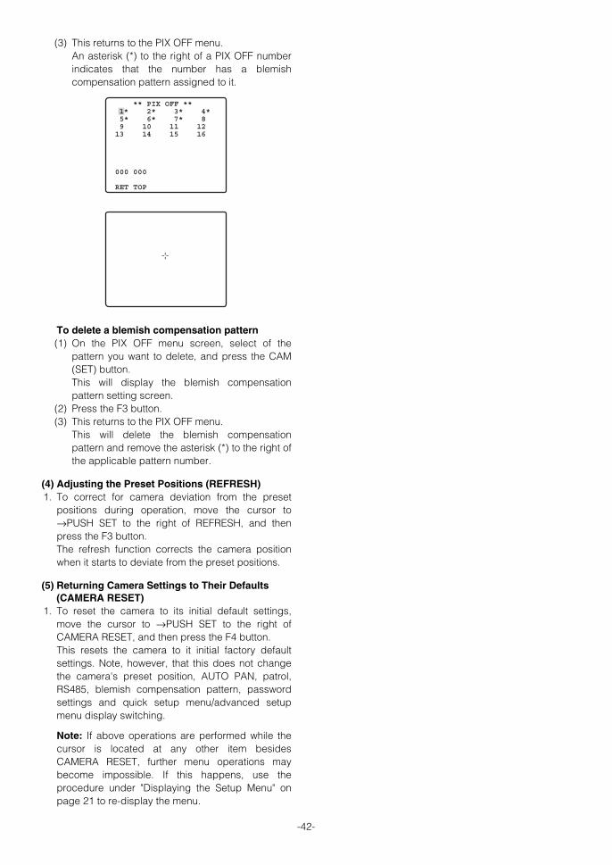
-42-
(3) This returns to the PIX OFF menu.An asterisk (*) to the right of a PIX OFF numberindicates that the number has a blemishcompensation pattern assigned to it.
To delete a blemish compensation pattern(1) On the PIX OFF menu screen, select of the
pattern you want to delete, and press the CAM(SET) button. This will display the blemish compensationpattern setting screen.
(2) Press the F3 button. (3) This returns to the PIX OFF menu.
This will delete the blemish compensationpattern and remove the asterisk (*) to the right ofthe applicable pattern number.
(4) Adjusting the Preset Positions (REFRESH) 1. To correct for camera deviation from the preset
positions during operation, move the cursor to→PUSH SET to the right of REFRESH, and thenpress the F3 button. The refresh function corrects the camera positionwhen it starts to deviate from the preset positions.
(5) Returning Camera Settings to Their Defaults(CAMERA RESET)
1. To reset the camera to its initial default settings,move the cursor to →PUSH SET to the right ofCAMERA RESET, and then press the F4 button. This resets the camera to it initial factory defaultsettings. Note, however, that this does not changethe camera's preset position, AUTO PAN, patrol,RS485, blemish compensation pattern, passwordsettings and quick setup menu/advanced setupmenu display switching.
Note: If above operations are performed while thecursor is located at any other item besidesCAMERA RESET, further menu operations maybecome impossible. If this happens, use theprocedure under "Displaying the Setup Menu" onpage 21 to re-display the menu.
** PIX OFF ** 2* 3* 4* 5* 6* 7* 8 9 10 11 12 13 14 15 16
000 000
RET TOP
1*
WV-CS954_E 09.1.21 2:58 PM ページ42

-43-
SCENE SELECT SETTING
■ Using the Scene Select SettingMenu
Display the scene select setting menu from the setupmenu to configure scene select settings. First, displaythe scene select setting menu. 1. Display the setup menu (page 21), move the cursor
to SCENE SELECT O, and then press the CAM(SET) button. This will display the scene select setting menu.
● Scene Select SettingsSee page 22 for information on the scene selectsettings method.
**SCENE SELECT**
SCENE INDOOR(L)
LOAD RET TOP
WV-CS954_E 09.1.21 2:58 PM ページ43

PASSWORD SETTINGS
■ Password Lock Settings Set the password lock on the setup menu.
● Turning Password Lock On and Off The password lock function can be used to allow onlyauthorized personnel to change camera settings. Apassword must be input in order to turn password lockon or off.
ON : Prohibits changing any settings except forthe password lock function.Selecting this setting limits cameraconfiguration changes to authorized personnel.
OFF : Settings on all menus can be changed.If you are using a VCR for recording, turn off recordingbefore inputting the password. Inputting the passwordwhile the picture is being recorded by a VCR will causethe password to be recorded with the picture. 1. Display the setup menu (page 24), move the cursor
to PASSWORD LOCK (ON or OFF), and then pressthe CAM (SET) button. This will display the password input menu.
2. To set the password for the first time, enter thefactory default password "123" and then press theCAM (SET) button.
Note: You must use this procedure. The passwordLock ON/OFF does not switch.
3. Input a 3-digit password by moving the cursor toeach of the applicable numbers along the top of thescreen (0 to 9) and pressing the CAM (SET) buttonfor each digit.
The ↑ pointer will move to the right each time youinput a digit. After you input all three digits, movethe cursor to OK. If you make a mistake during input, move the cursorto RESET, press the CAM (SET) button, and then re-input the entire password.
Note: The factory default password is 123.
4. Press the CAM (SET) button. This returns to the setup menu and togglesPASSWORD LOCK on or off. The password input screen will reappear if youpress the CAM (SET) button after inputting thewrong password. If this happens, perform step 3again.
● Changing the Password After turning on password lock, it is recommended thatyou use the following procedure to change the factorydefault password to a different one. Also, make sureyou keep a separate record of your password so youdo not forget it. If you are using a VCR for recording, turn off recordingbefore inputting the password. Inputting the passwordwhile the picture is being recorded by a VCR will causethe password to be recorded with the picture. 1. Display the setup menu (page 24), move the cursor
to PASSWORD LOCK (ON or OFF), and then pressthe CAM (SET) button. This will display the password input menu.
2. Input the current 3-digit password by moving thecursor to each of the applicable numbers along thetop of the screen (0 to 9) and pressing the CAM(SET) button for each digit. The ↑ pointer will move to the right each time youinput a digit. After you input all three digits, movethe cursor to OK. If you make a mistake during input, move the cursorto RESET, press the CAM (SET) button, and then re-input the entire password.
-44-
MODEL WV-CS954CAMERAPAN/TILTALARMSPECIALCOMMUNICATIONSCENE SELECTLANGUAGE
→QUICK SETUPPASSWORD LOCK OFF
** PASSWORD? **
0 1 2 3 4 5 6 7 8 9
. . .
OK RESETNEW PASSWORD RET TOP
MODEL WV-CS954CAMERAPAN/TILTALARMSPECIALCOMMUNICATIONSCENE SELECTLANGUAGE
→QUICK SETUPPASSWORD LOCK OFF
** PASSWORD? **
0 1 2 3 4 5 6 7 8 9
. . .
OK RESETNEW PASSWORD RET TOP
WV-CS954_E 09.1.21 2:58 PM ページ44

-45-
3. Move the cursor to NEW PASSWORD and press theCAM (SET) button to display the password settingmenu. The password input screen will reappear if youpress the CAM (SET) button after inputting thewrong password. If this happens, perform steps 2and 3 again.
4. Input the new 3-digit password by moving thecursor to each of the applicable numbers along thetop of the screen (0 to 9) and pressing the CAM(SET) button for each digit. After you input all three digits, move the cursor toOK.
5. Press the CAM (SET) button. This returns to the new password input screenagain for verification. Note that you cannot register the new password bypressing the MON (ESC) button.
6. Input the new 3-digit password again by moving thecursor to each of the applicable numbers along thetop of the screen (0 to 9) and pressing the CAM(SET) button for each digit. After you input all three digits, move the cursor toOK.
7. Press the CAM (SET) button. This completes the password change operationand returns to the setup menu. If the new passwordyou input in step 6 is different from the one youinput in step 4, the new password input screen willappear again. If this happens, perform steps 4through 7 again. Note that you cannot register thenew password by pressing the MON (ESC) button.
** NEW PASSWORD? **
0 1 2 3 4 5 6 7 8 9
. . .
. . .
OK RESET
RET TOP
WV-CS954_E 09.1.21 2:58 PM ページ45

-46-
SHORTCUTS
Shortcuts are supported when you are using the system controller that has a CAM FUNCTION button. With shortcuts,you can configure camera functions by inputting function codes on the 10-key pad and then pressing the CAMFUNCTION button. The following is a list of all of the shortcuts that are supported by this camera. In addition, you can also move thecamera to a preset position by inputting the applicable position number on the 10-key pad.
Notes:• Turn off digital flip before registering preset positions. If NO REGS.; FLIP ON appears, do the setting again. • Shortcuts may not be performed if they are executed while a pan, tilt, zoom, or focus operation is in progress. • Shortcuts 1 through 64, 169, 170, and 301~556 can be saved as part of a patrol routine. • Except for shortcuts 169 and 170, executing any shortcut during patrol routine PLAY will cause the PLAY
operation to stop.
Controller Operation Setting
[6] + [5] + [CAM FUNCTION] AUTO PAN ON
[6] + [6] + [CAM FUNCTION] AUTO PAN OFF
[6] + [7] + [CAM FUNCTION] Increases AUTO PAN speed one step.
[6] + [8] + [CAM FUNCTION] Decreases AUTO PAN speed one step.
[6] + [9] + [CAM FUNCTION] Sets AUTO PAN start point.
[7] + [0] + [CAM FUNCTION] Sets AUTO PAN end point.
[7] + [1] + [CAM FUNCTION] AUTO MODE: OFF
[7] + [2] + [CAM FUNCTION] AUTO MODE: SEQ ON
[7] + [3] + [CAM FUNCTION] AUTO MODE: SORT ON
[7] + [4] + [CAM FUNCTION] Reverses AUTO PAN range.
[7] + [6] + [CAM FUNCTION] ENDLESS: ON
[7] + [7] + [CAM FUNCTION] ENDLESS: OFF
[7] + [8] + [CAM FUNCTION] DIGITAL FLIP: ON
[7] + [9] + [CAM FUNCTION] DIGITAL FLIP: OFF
[8] + [0] + [CAM FUNCTION] PROPO.P/T: ON
[8] + [1] + [CAM FUNCTION] PROPO.P/T: OFF
[8] + [4] + [CAM FUNCTION] SUPER-D 3: ON
[8] + [5] + [CAM FUNCTION] SUPER-D 3: OFF
[8] + [6] + [CAM FUNCTION] AF MODE: AUTO
[8] + [7] + [CAM FUNCTION] AF MODE: MANUAL
[8] + [8] + [CAM FUNCTION] Performs auto focus.
[8] + [9] + [CAM FUNCTION] Moves to home position.
[9] + [0] + [CAM FUNCTION] BW: ON
[9] + [1] + [CAM FUNCTION] BW: OFF
[9] + [2] + [CAM FUNCTION] BW: AUTO
[9] + [3] + [CAM FUNCTION] CAMERA ID: ON
[9] + [4] + [CAM FUNCTION] CAMERA ID: OFF
[9] + [5] + [CAM FUNCTION] AREA TITLE: ON (NESW)
[9] + [6] + [CAM FUNCTION] AREA TITLE: ON (USER)
[9] + [7] + [CAM FUNCTION] AREA TITLE: OFF
[1] + [0] + [0] + [CAM FUNCTION] Adjusts camera position (REFRESH)
[1] + [0] + [1] + [CAM FUNCTION]~ Registers a position to a preset number (1 to 64).
[1] + [6] + [4] + [CAM FUNCTION]
[1] + [6] + [5] + [CAM FUNCTION] PATROL1: PLAY
[1] + [6] + [6] + [CAM FUNCTION] PATROL1 - PATROL4: STOP
[1] + [6] + [7] + [CAM FUNCTION] PATROL1: LEARN start
[1] + [6] + [9] + [CAM FUNCTION] IRIS: OPEN
WV-CS954_E 09.1.21 2:58 PM ページ46

-47-
Controller Operation Setting
[1] + [7] + [0] + [CAM FUNCTION] IRIS: CLOSE
[1] + [7] + [1] + [CAM FUNCTION] SHUTTER: ON
[1] + [7] + [2] + [CAM FUNCTION] SHUTTER: OFF
[1] + [7] + [3] + [CAM FUNCTION] Increases shutter speed one step.
[1] + [7] + [4] + [CAM FUNCTION] Decreases shutter speed one step.
[1] + [7] + [5] + [CAM FUNCTION] AGC: ON
[1] + [7] + [6] + [CAM FUNCTION] AGC: OFF
[1] + [7] + [7] + [CAM FUNCTION] SENS UP: FIX ON
[1] + [7] + [8] + [CAM FUNCTION] SENS UP: FIX OFF
[1] + [7] + [9] + [CAM FUNCTION] Increases electronic sensitivity enhancement (FIX) one step.
[1] + [8] + [0] + [CAM FUNCTION] Decreases electronic sensitivity enhancement (FIX) one step.
[1] + [8] + [1] + [CAM FUNCTION] SENS UP: AUTO ON
[1] + [8] + [2] + [CAM FUNCTION] SENS UP: AUTO OFF
[1] + [8] + [3] + [CAM FUNCTION] Increases electronic sensitivity enhancement (AUTO) one step.
[1] + [8] + [4] + [CAM FUNCTION] Decreases electronic sensitivity enhancement (AUTO) one step.
[1] + [8] + [5] + [CAM FUNCTION] Increases line lock phase (FINE) one step.
[1] + [8] + [6] + [CAM FUNCTION] Decreases line lock phase (FINE) one step.
[1] + [8] + [7] + [CAM FUNCTION] Pans 180° .
[1] + [8] + [8] + [CAM FUNCTION] CLEANING: ON
[1] + [8] + [9] + [CAM FUNCTION] CLEANING: OFF
[1] + [9] + [0] + [CAM FUNCTION] BW AUTO switching time: 10 seconds
[1] + [9] + [1] + [CAM FUNCTION] BW AUTO switching time: 30 seconds
[1] + [9] + [2] + [CAM FUNCTION] BW AUTO switching time: 60 seconds
[1] + [9] + [3] + [CAM FUNCTION] BW AUTO switching time: 300 seconds
[1] + [9] + [4] + [CAM FUNCTION] PATROL2: PLAY
[1] + [9] + [5] + [CAM FUNCTION] PATROL3: PLAY
[1] + [9] + [6] + [CAM FUNCTION] PATROL4: PLAY
[1] + [9] + [7] + [CAM FUNCTION] PATROL2: LEARN start
[1] + [9] + [8] + [CAM FUNCTION] PATROL3: LEARN start
[1] + [9] + [9] + [CAM FUNCTION] PATROL4: LEARN start
[2] + [0] + [0] + [CAM FUNCTION] Turns on auto tracking.
[2] + [0] + [1] + [CAM FUNCTION] STABILIZER: ON
[2] + [0] + [2] + [CAM FUNCTION] STABILIZER: OFF
[2] + [0] + [3] + [CAM FUNCTION] PAN, TILT, ZOOM, coordinate display ON
[2] + [0] + [4] + [CAM FUNCTION] PAN, TILT, ZOOM, coordinate display OFF
[2] + [0] + [5] + [CAM FUNCTION] Alarm display ON
[2] + [0] + [6] + [CAM FUNCTION] Alarm display OFF
[3] + [0] + [1] + [CAM FUNCTION]~ Moves to a preset number (1 to 256).*
[5] + [5] + [6] + [CAM FUNCTION] Example: Preset number 128 → [4] + [2] + [8] + [CAM FUNCTION]
[6] + [0] + [1] + [CAM FUNCTION]~ Registers a position to a preset number (1 to 256).*
[8] + [5] + [6] + [CAM FUNCTION] Example: Preset number 128 → [7] + [2] + [8] + [CAM FUNCTION]
* Do not do this operation with the previous dome type camera models (WV-CS850, WV-CS854 series, WV-CW860, WV-CW864 series, WV-CS564, WV-CS570 and WV-CS574 series), doing so may cause a malfunction.
WV-CS954_E 09.1.21 2:58 PM ページ47

TROUBLESHOOTING
Before requesting service, check the following symptoms to see if you can solve the problem yourself. If the countermeasures described below do not correct the problem, or if the symptoms you are experiencing are notcovered here, contact a quality service person or system installer.
-48-
Problem Cause and Recommended Action Reference Pages
No picture (dark screen)
• Is the camera connected correctly? Check theoperating instructions that come with your systemcontroller.
—
• Is the lens iris closed?
Execute the iris reset from the system controller youare using.
25-26
• Is the camera set up for a fixed shutter speed? 26
White picture
• Is FIX selected for the electronic sensitivityenhancement (SENS UP) setting?
26
• Is the lens iris open? 25-26
Out of focus picture
• Is the dome cover or lens of the camera dirty? If so,clean them.
7
• Is the object one that is not compatible with autofocus? For such objects, focus manually. 29
Digital noise in thepicture
• The slip ring may be dirty. Do you have thecleaning function turned on?
37
• Is the camera set up correctly? 11
• Is MANUAL selected for the auto focus mode? 29
WV-CS954_E 09.1.21 2:58 PM ページ48

-49-
Problem Cause and Recommended Action Reference Pages
Poor picture color
• Is the dome cover or lens of the camera dirty? If so,clean them. 7
• Use the special setup menu to adjust picturequality.
41
• Check the white balance setting. 27-28
Image flicker • If Super Dynamic 3 is turned on, turn it off. 25-26
Afterimages in the picture
• Check the DNR setting. 28
Black and white picture• The camera has an auto black and white switching
mode function. Check the setting of this mode. 28
Frequent switchingbetween the color andthe black and whitemodes
• Adjust the black and white mode switching level,and the duration time setting. 28
White specks in thepicture
• Use the PIX OFF function to perform blemishcompensation. 41-42
Menu does not open.
• Is the camera connected correctly? See theoperating instructions that come with the systemcontroller you are using.
—
• Are camera communication settings configuredcorrectly?
12-14
18-19
20
A circular objectappear in the picture(when the camera ispointing straight down)
• This is caused by the shape of the dome cover andis not a malfunction.
7
WV-CS954_E 09.1.21 2:58 PM ページ49

-50-
Menu settings will notchange.
• Is the password lock function turned on? 44
I forgot the password. • Contact a quality service person or system installer. —
Picture does not switchto black and white.
• Switching is not performed when the ALARM IN 4setting is BW. Check the setting. 40
Pan, tilt, zoom, or focusdo not work.
• Is the camera connected correctly? See theoperating instructions that come with the systemcontroller you are using.
—
• The camera has a pan limit function. Check thePAN LIMIT settings.
33
• The motor or lens may be worn. Contact a qualityservice person or system installer.
—
Problem Cause and Recommended Action Reference Pages
The camera movementmodes (OFF, SEQ,SORT, AUTO PAN,PATROL, AUTOTRACK) do not work.
• Check the self return function. 32
• Check the ALARM IN settings. 39-40
• Check the recover time setting of the motiondetector.
38-39
WV-CS954_E 09.1.21 2:58 PM ページ50

-51-
Power cord sheathing isdamaged.
• The power cord, connector, or power plug is damaged. Continueduse creates the risk of electric shock and fire. Immediately unplugthe power plug and contact a qualified service person or systeminstaller for servicing.
Power cord becomeshot during operation.
Power cord becomeswarm or hot when it isbent or stretched duringuse.
● Periodically check the power cord.
The camera movementmode (OFF, SEQ,SORT, AUTO PAN,PATROL, AUTOTRACK) settingchanges.
• Check the self return function. 32
Problem Cause and Recommended Action Reference Pages
Camera position isdifferent from thepreset position setting.
• Perform REFRESH from the special setup menu. 42
Picture is different fromthe position setting.
• Adjust the picture using the preset menu and ascene file.
30-31
Upper part of the pictureis black when the camerais in a horizontalorientation.
• This is caused by the camera's internal cover. Itdoes not indicate malfunction.
37
Camera suddenly startsto pan by itself.
• If the cleaning function is turned on, this is normaldoes not indicate malfunction. Check theCLEANING settings.
37
• If the cleaning function is not turned on, thissymptom could be due to noise.
8, 11
WV-CS954_E 09.1.21 2:58 PM ページ51

-52-
● GeneralPower Requirements 24 V AC, 60 HzPower Consumption 13 WPick-up Device 1/4-type {1/4"} interline transfer CCDEffective Pixels 768 (H) × 494 (V)Scanning Area 3.65 mm (H) × 2.74 mm (V)Signal NTSCSynchronization Internal (INT), multiplexed vertical drive (VD2), link-lock (LL)Scanning 2:1 interlaceScanning Frequencies Horizontal: 15.734 kHz, Vertical: 59.94 HzVideo Output VBS: 1.0 V [P-P]/75 Ω (BNC plug)Resolution (Center) Horizontal : 480 lines minimum (color NORMAL mode)
540 lines typ. , 520 lines minimum (color HIGH mode)570 lines minimum (black and white)
Vertical : 350 lines minimum (Center)Minimum Illumination 0.5 lux{fc} (color mode)
0.04 lux{fc} (black and white mode) SENS UP: OFF; AGC: HIGH
Dynamic Range 52 dB typ. (SUPER-D3: ON) S/N Ratio 50 dB minimum (AGC: OFF) Ambient Operating Temperature -10 °C to +50 °C (Less than +35 °C is recommended) ;
Humidity 90 % max. (non-condensation)Dimensions 154.5 mm(D) × 233 mm(H) {6-5/64"(D) × 9-11/64"(H)}Weight Approximately 2.2 kg {4.9 lbs}Finish Camera: Die cast aluminum with baked melanin coating (Paint color: Fine silver)
Dome: Clear acrylic resin
● Pan and Tilt Panning Range 360 ° endlessPanning Modes Manual, auto, manual position, sequential position Panning Speed* Manual: Approximately 0.065 °/s to 120 °/s 8 steps, 16 steps, 64 steps
Preset: Approximately 400 °/sTilting Range -5 ° to 185 ° (horizontal - vertical - horizontal)
(According to the TILT ANGLE)Tilting Modes Manual, manual position, sequential position Tilting Speed* Manual: Approximately 0.065 °/s to 120 °/s 8 steps, 16 steps, 64 steps
Preset: Approximately 400 °/s
* Actual speed depends on type of controller being used.
● LensZoom Ratio 30x (Approximately 300x with digital zoom) Focal Length 3.8 mm to 114 mmMaximum Aperture Ratio 1:1.4 (WIDE) to 3.7 (TELE) Object Distance 1.5 mIris Range F1.4 to 22, CloseAngular Field of View Horizontal: 1.9 ° (TELE) to 52 ° (WIDE)
Vertical: 1.4 ° (TELE) to 40 ° (WIDE)
SPECIFICATIONS
WV-CS954_E 09.1.21 2:58 PM ページ52
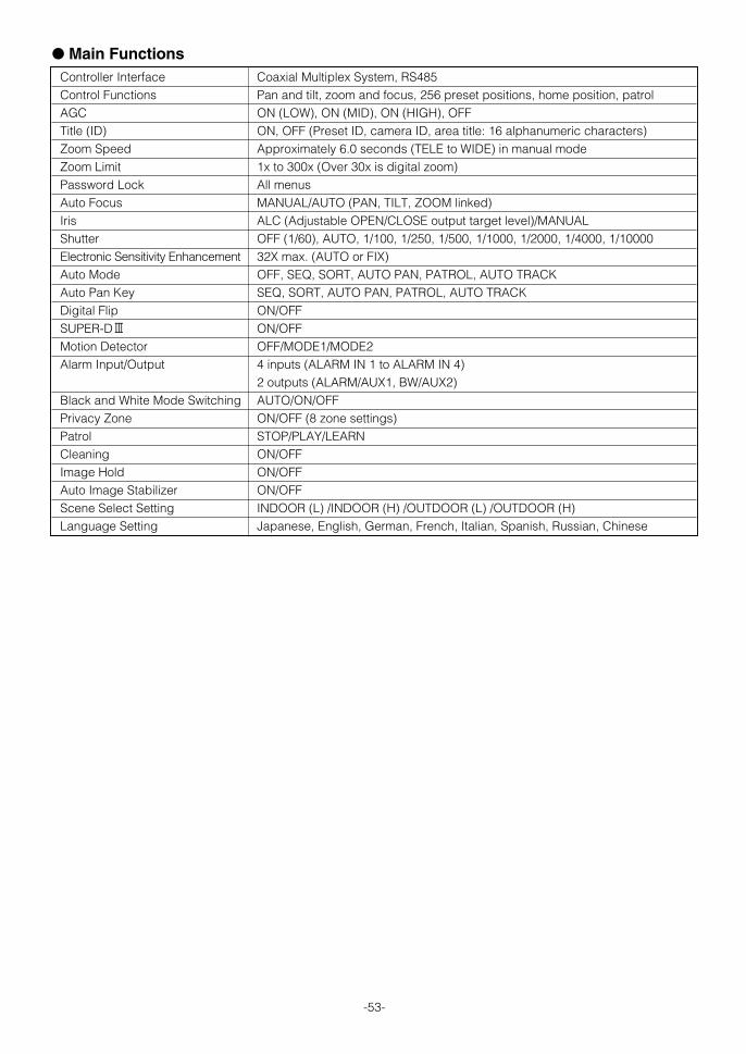
-53-
● Main FunctionsController Interface Coaxial Multiplex System, RS485Control Functions Pan and tilt, zoom and focus, 256 preset positions, home position, patrolAGC ON (LOW), ON (MID), ON (HIGH), OFFTitle (ID) ON, OFF (Preset ID, camera ID, area title: 16 alphanumeric characters) Zoom Speed Approximately 6.0 seconds (TELE to WIDE) in manual mode Zoom Limit 1x to 300x (Over 30x is digital zoom)Password Lock All menus Auto Focus MANUAL/AUTO (PAN, TILT, ZOOM linked) Iris ALC (Adjustable OPEN/CLOSE output target level)/MANUALShutter OFF (1/60), AUTO, 1/100, 1/250, 1/500, 1/1000, 1/2000, 1/4000, 1/10000Electronic Sensitivity Enhancement 32X max. (AUTO or FIX)Auto Mode OFF, SEQ, SORT, AUTO PAN, PATROL, AUTO TRACKAuto Pan Key SEQ, SORT, AUTO PAN, PATROL, AUTO TRACKDigital Flip ON/OFFSUPER-D3 ON/OFFMotion Detector OFF/MODE1/MODE2Alarm Input/Output 4 inputs (ALARM IN 1 to ALARM IN 4)
2 outputs (ALARM/AUX1, BW/AUX2)Black and White Mode Switching AUTO/ON/OFFPrivacy Zone ON/OFF (8 zone settings) Patrol STOP/PLAY/LEARN Cleaning ON/OFFImage Hold ON/OFFAuto Image Stabilizer ON/OFFScene Select Setting INDOOR (L) /INDOOR (H) /OUTDOOR (L) /OUTDOOR (H)Language Setting Japanese, English, German, French, Italian, Spanish, Russian, Chinese
WV-CS954_E 09.1.21 2:58 PM ページ53

-54-
MISE EN GARDE:• Cet appareil doit être mis à la terre.• Afin de prévenir tout risque d’incendie ou d’électrocution, éviter d’exposer cet appareil à la pluie ou à une humidité
excessive.• Cet appareil ne doit pas être exposé aux égouttements d’eau et aux éclaboussures. S’assurer qu’aucun objet
rempli de liquide, tel qu’un vase, n’est placé sur l’appareil.• Tous les travaux en rapport avec l’installation de cet appareil doivent être effectués par du personnel d’entretien
ou des installateurs de systèmes qualifiés.
L'éclair à extrémité fléchée placé dansun triangle équilatéral est destiné àattirer l'attention de l'utilisateur sur laprésence d'une "tension potentiel-lement dangereuse" et non isolée setrouvant dans les limites du coffret del'appareil dont la puissance est suf-fisante pour constituer un risque impor-tant d'électrocution.
Le point d'exclamation placé dans untriangle équilatéral sert à attirer l'atten-tion de l'utilisateur sur des instructionsde fonctionnement et d'entretien (dedépannage) à caractère importantdans la brochure qui accompagne l'ap-pareil.
Le numéro de série de l'appareil se trouve sur laplaque supérieure.Nous vous conseillons de relever le numéro de sériede votre appareil dans l'espace réservé ci-dessouset de conserver précieusement votre notice d'instruc-tions en tant que justificatif d'achat aux fins d'identifi-cation en cas de vol.
No. de modèle
No. de série
ATTENTION:AFIN DE PRÉVENIR LE RISQUE DE CHOCSÉLECTRIQUES, NE PAS RETIRER LES VIS.
TOUTE RÉPARATION DEVRAIT ÊTRECONFIÉE À UN PERSONNEL QUALIFIÉ.
CAUTION ATTENTIONRISK OF ELECTRIC SHOCK DO NOT OPEN
RISQUE DE CHOCS ELECTRIQUES NE PAS OUVRIR
SA 1965
SA 1966
L’interférence radioélectrique générée par cet appareilnumérique de type A ne dépasse pas les limites radio-électriques, section appareil numérique, du Ministère desCommunications.
Cet appareil numérique de la classe A est conforme à lanorme NMB-003 du Canada.
VERSION FRANÇAIS(FRENCH VERSION)
WV-CS954_FR 09.1.21 2:55 PM ページ54

-55-
FRAN
ÇAIS
INSTRUCTIONS DE SÉCURITÉ IMPORTANTES
1) Veuillez lire ces instructions.
2) Conservez ces instructions.
3) Tenir compte de tous les avertissements.
4) Conformez-vous à toutes les instructions.
5) Ne pas utiliser cet appareil près de lieux en présence d'eau.
6) Nettoyer uniquement avec un chiffon sec.
7) N'obturer aucune des ouvertures d'aération. Installer conformément aux instructions du fabricant.
8) Ne pas installer à proximité de sources de chaleur, telles que des radiateurs, des bouches de chauffage, des appareilsde chauffage ou tout autre appareil (y compris les amplificateurs) produisant de la chaleur.
9) Ne pas asservir l'objectif de sécurité de la prise polarisée ou de la prise de mise à la terre. Une prise polarisée possèdedeux lames dont l'une est plus large que l'autre. Une prise de mise à la terre possède deux lames ainsi qu'un troisièmeélément, un ergot de mise à la terre. La lame qui est large ou le troisième élément, l'ergot, sont installés pour assurervotre sécurité. Si la prise fournie ne s'engage pas correctement dans votre prise, veuillez consulter un électricien pourqu'il effectue le remplacement de l'ancienne prise de sortie secteur.
10) Protéger le cordon d’alimentation afin que personne ne marche dessus et que le cordon ne soit pas pincé, notammentau niveau des prises, des prises pratiques et du point de sortie de l’appareil.
11) Utiliser uniquement les fixations ou les accessoires spécifiés par le fabricant.
12) Utiliser uniquement le chariot, le support, le trépied, la platine de fixation ou la tablette spécifiée par le fabricant ouvendu avec l'appareil. Quand un chariot est utilisé, prendre toutes les précautions nécessaires lors du déplacement dela combinaison chariot-appareil afin que le tout ne se renverse pas.
13) Débrancher cet appareil pendant les orages électriques ou s'il n'est pas utilisé sur de longues périodes de temps.
14) Toute réparation ou dépannage doit Ítre confié à un personnel qualifié. Un dépannage est nécessaire lorsque l'appareila été endommagé d'une manière quelconque, par exemple, lorsque le cordon d'alimentation électrique ou la prise sontendommagés, si un liquide s'est répandu dessus ou si des objets sont tombés dans l'appareil, lorsque l'appareil a étéexposé à la pluie ou à l'humidité, ne fonctionne pas normalement ou s'il a fait une chute.
S3125A
WV-CS954_FR 09.1.21 2:55 PM ページ55

-56-
LIMITATION DE RESPONSABILITÉ
DÉNI DE LA GARANTIE
CETTE PUBLICATION EST FOURNIE "COMME TEL" SANSGARANTIE DE TOUTE SORTE, EXPRÈS OU IMPLICITE,ÉTANT INCLUSE MAIS NON LIMITÉE AUX GARANTIESIMPLICITES DE LA VALEUR MARCHANDE, ADAPTATIONPOUR TOUT BUT PARTICULIER OU NON-INFRACTIONDES DROITS D'UN TIERS.
CETTE PUBLICATION A PU INCLURE DES INEXACTI-TUDES TECHNIQUES OU DES ERREURSTYPOGRAPHIQUES. DES CHANGEMENTS SONTAJOUTÉS AUX INFORMATION CI-DESSUS, À TOUTMOMENT, AUX FINS D'AMÉLIORATION DE CETTE PUB-LICATION ET/OU DU PRODUIT CORRESPONDANT (S).
EN AUCUN CAS Panasonic Corporation NE PEUT ÊTRETENU POUR RESPONSABLE POUR TOUT PARTI OUTOUTE PERSONNE, À L'EXCEP-TION DE DUREMPLACEMENT OU D'UN ENTRETIEN RAISONNABLEDE CE PRODUIT POUR LES CAS, Y COMPRIS MAIS NONLIMITÉ À CE QUI EST MENTIONNÉ CI-DESSOUS:
(1) TOUT DÉGÂT ET PERTE, Y COMPRIS SANS LIMITA-TION, DIRECT OU INDIRECT, SPÉCIAL, IMPORTANTOU EXEMPLAIRE, SURVENANT OU CONCERNANTLE PRODUIT;
(2) BLESSURE PERSONNELLE OU TOUT DÉGÂTCAUSÉS PAR UN USAGE NON APPROPRIÉ OU UNEUTILISA-TION NÉGLIGENTE DE L'UTILISATEUR;
(3) DÉMONTAGE, RÉPARATION OU MODIFICATIONNON AUTORISÉS DU PRODUIT EFFECTUÉS PARL'UTILISA-TEUR;
(4) LES INCONVÉNIENTS OU PERTES QUI SURVIEN-NENT SI LES IMAGES NE SONT PAS AFFICHÉES, DUFAIT D'UNE QUELCONQUE RAISON OU CAUSEINCLUANT UNE QUELCONQUE PANNE OUPROBLÈME INHÉRENT AU PRODUIT.
(5) TOUT PROBLÈME, INCOMMODITÉ IMPORTANTE DECONSÉQUENCE OU PERTE OU ENDOMMAGEMENT,SURVENANT DU SYSTÈME COMBINÉ PAR DESAPPAREILS DE TIERS.
(6) TOUTE RÉCLAMATION OU ACTION ENTREPRISEPOUR DES DOMMAGES, APPORTÉE PAR TOUTEPERSONNE OU ORGANISATION ÉTANT UN SUJETPHOTOGÈNE, DÛ À LA VIOLATION DE L'INTIMITÉAVEC POUR RÉSULTAT DES IMAGES DE SURVEIL-LANCE DE CAMÉRA VIDÉO, Y COMPRIS DESDONNÉES SAUVEGARDÉES, POUR UNE RAISONQUELCONQUE, EST DIFFUSÉE PUBLIQUEMENT OUEST EMPLOYÉE POUR UN BUT AUTRE QUE CELADE LA SURVEILLANCE
(7) TOUT PROBLÈME, INCOMMODITÉ CONSÉCUTIVEIMPORTANTE OU PERTE OU DOMMAGES, SUR-VENANT DE LA DÉTECTION INAPPROPRIÉE OUINTRODUCTION DANS LA DÉTECTION PAR LAFONCTION VMD (Détection de mouvement vidéo) DUPRODUIT.
WV-CS954_FR 09.1.21 2:55 PM ページ56

-57-
Cette caméra couleur CCTV est un appareil devidéosurveillance qui incorpore un dispositif à transfert decharge CCD de 1/4 de pouce, un zoom grossissant 30x,préréglée et des capacités de balayage panoramique etde réglage d’inclinaison dans une configuration en dôme.Cet appareil offre également les caractéristiquessuivantes.
■ Super Dynamic 33 (SUPER-D 33)Le processeur SUPER-D 3 rend possible la captured’images claires de sujets diversement éclairés (page 77).
■ Nouveau DSP pour une haute sensibilitéUn nouveau système de réduction de bruit réduit laluminance minimum à 0,5 lux{fc} en mode couleur et à0,04 en mode noir et blanc.
■ Passage automatique de nuit en modeNoir et blanc
Cette caméra peut être configurée de manière à passerautomatiquement en mode noir et blanc dans desconditions de faible lumière pour obtenir des imagesclaires même de nuit.
■ Digital Flip (retournement numérique)Une caméra doit normalement s’arrêter pour pointer versle bas pendant une opération de retournement. Avec leretournement numérique, la caméra peut s’incliner de 0 à180 ° d’un seul mouvement. Il devient ainsi possible desuivre sans problème des sujets passant directement sousla caméra
■ Fonction Zone de confidentialitéLa fonction Zone de confidentialité permet de masquerdes zones spécifiques de manière qu’elles n’apparaissentpas.
■ Fonction PatrouilleLa fonction patrouille garde en mémoire les mouvementsde routine manuels de la caméra pour pouvoir les relire encas de nécessité. Vous pouvez ainsi apprendre à lacaméra les mouvements des personnes à surveiller, enrelisant les paramètres mis en mémoire, les mouvementsautomatiques sont faits automatiquement.
■ Mémoire de position caméraLe système peut être configuré avec 256 positions caméraau maximum. Une position caméra particulière peut êtresélectionné et vue en saisissant le numéro de prérégléeapplicable sur le clavier à 10 touches.
■ Détection de mouvementLe système peut être configuré de sorte que le moindremouvement sur l’écran de surveillance déclenchel’émission d’un signal d’alarme. Cette fonction peut être utilisée avec un système demagnétoscope pour enregistrer des images d'intrusionnocturne.
DÉNI DE LA GARANTIECARACTÉRISTIQUES
ACCESSOIRES
Mode d’emploi (ce manuel) . . . . . . . . . . . . . . . . . . . . .1 élCertificat de garantie . . . . . . . . . . . . . . . . . . . . . . . . . .1 él
Les éléments suivants sont nécessaires à l’installation.Couvercle décoratif . . . . . . . . . . . . . . . . . . . . . . . . . . .1 élFeuille de protection contre la poussière . . . . . . . . . . .1 élCâble d’alarme 8P . . . . . . . . . . . . . . . . . . . . . . . . . . . .1 élCâble d’alarme 4P . . . . . . . . . . . . . . . . . . . . . . . . . . . .1 élConnecteur pour 24 V CA . . . . . . . . . . . . . . . . . . . . . .1 él
Fonctionnement de la bascule numérique
Inclinaison vers le bas
L’image se retourne lorsque la caméra est pointée vers le bas (environ 135°).
Inclinaison vers le haut.
. . . La bascule numérique est effectuée uniquement lorsque la manette de contrôle est tenue vers le bas.
ACCESSOIRES EN OPTION
Couvercle de dôme (transparent à environ 50 %, type fumé) . . . . .WV-CS3SSupport de montage plafond . . . . . . . . . . . . . . . . . . . . . . . . . . . . . . .WV-Q105/WV-Q116/WV-Q117Support de montage mural . . . . . . . . . . . . . . . . . . . . . . . . . . . . . . . .WV-Q118
WV-CS954_FR 09.1.21 2:55 PM ページ57

-58-
MESURES DE PRÉCAUTIONS
1. Ne jamais tenter de démonter la caméra.Pour éviter tout risque d’électrocution, ne pas enlevervis ou couvercles.Il n’y a aucune pièce réparable par l’utilisateur àl’intérieur. Adressez-vous à des techniciens dépanneurs qualifiéspour toute réparation.
2. Manipuler soigneusement la caméra.Ne pas employer improprement la caméra. Évitez de lasecouer, de lui faire subir des chocs etc. La camérapourrait être endommagée par de mauvaisesconditions de rangement ou de manipulation.
3. Ne jamais exposer la caméra à la pluie ou à l’humid-ité, et n’essayez pas de la faire fonctionner en zonehumide.Ce produit est destiné à une utilisation en intérieur ou àdes lieux abrités de la pluie ou de l’humidité.Mettez l’appareil immédiatement hors tension etdemandez l’aide d’un technicien qualifié pour ledépannage.L’humidité peut endommager la caméra et créer undanger d'électrocution.
4. Ne jamais se servir de détergents abrasifs et vio-lents pour nettoyer le caisson de la caméra. Utilisez un chiffon sec pour nettoyer la caméra en casde besoin. Si la saleté est difficile à enlever, utilisez un détergentdoux et frottez délicatement. Il faut faire extrêmementattention à ne pas rayer le dôme en l’essuyant. Avec un chiffon sec retirez toute trace de détergentpour terminer.
5. Ne jamais pointer la caméra vers le soleil.Que la caméra soit ou non en service, ne la pointezjamais directement vers le soleil ou vers d’autres objetsextrêmement lumineux. Cela peut entraîner un traînageou une hyper luminosité.
6. Ne dirigez jamais la caméra vers de puissantessources d’éclairage pendant de longs momentsUne lumière telle celle d’un projecteur risque defavoriser la formation d’une tache rémanente surl’écran d’affichage. Le fait de ne pas respecter cettemise en garde, peut produire une image décoloréesuite à la détérioration du filtre couleur intégré dans ledispositif à transfert de charge CCD.
7. Ne jamais installer cette caméra en positioninversée.Cette caméra est conçue pour être installée sur unplafond ou un mur. Le fait de l’installer en positioninversée par exemple sur un plancher, peut avoir poureffet d’empêcher un fonctionnement normal.
8. Ne jamais faire fonctionner la caméra dans des con-ditions excédant ses limites d’utilisation en termesde température, d’humidité ou de puissance d’ali-mentation.Evitez d’utiliser la caméra dans un milieu extrême avecdes conditions de température ou d’humidité trèsélevées. La caméra ne doit pas être placée près desources de chaleur telles que des radiateurs, despoêles ou tout autre appareil produisant de la chaleur. Elle doit être utilisée dans des conditions detempérature ambiante située entre -10 °C et + 50 °C{14 °F - 122 °F} (et de préférence +40 °C {104 °F})avec une humidité inférieure à 90 %.La source d’alimentation est de 24 V de courantalternatif 60 Hz.
9. La caméra ne doit pas être installée près d’unebouche d’aération d'air conditionné.L’objectif risque de s’embuer en raison de lacondensation si la caméra vidéo est utilisée dans lesconditions suivantes.
• Variations rapides de température suite à la mise enmarche ou l’arrêt de l’air conditionné.
• Variations rapides de température en raison d'uneouverture et d'une fermeture fréquentes des portes.
• Utilisation dans un environnement où les lunettess’embuent.
• Utilisation dans une pièce remplie de fumée decigarettes ou de poussière. Si l’objectif s’embue, suite à une condensation, retirezle couvercle du dôme et éliminez l’humidité dessurfaces avec un chiffon doux.
10. Pièces de remplacementLes pièces munies de contacts telles que les moteursd’entraînement d’objectif, le moteur du ventilateur derefroidissement et les bagues collectrices à l'intérieurde la caméra vidéo, sont sujettes à usure avec letemps. Demandez au centre après vente le plusproche d’effectuer le remplacement et l’entretien deces pièces.
11. Ne pas diriger la caméra vidéo vers le même sujetpendant un long moment.Une rémanence d’image risque de se produire surl’écran fluorescent du tube à rayons cathodiques.
12. Fonction d’auto diagnosticSi la caméra vidéo continue de fonctionner de façonanormale pendant plus de 30 secondes du fait deproblème tels des bruits externes, elle redémarreautomatiquement. Si cela se produit fréquemment,vérifiez s’il existe une raison liée à l’environnement.
* Nous, Panasonic Corporation déclarons ci-après quenous ne serions être tenu pour responsable desdommages survenus, directs ou indirects, parl’utilisation de ce produit pour une transactioncommerciale ou pour la sécurité, ou par un défaut deson fonctionnement.
WV-CS954_FR 09.1.21 2:55 PM ページ58

-59-
PRÉCAUTIONS PENDANT LE FONCTIONNEMENT
■ La caméra vidéo n’est pas équipée d’un commuta-teur d’alimentation.
La mise sous tension est immédiate dès que le cordond’alimentation est branché. Avant de procéder aunettoyage de la caméra vidéo, débranchez le cordond’alimentation de la prise de courant.
■ Que faire si le message OVER HEAT apparaît surl’écran
Ce message indique que la température interne de lacaméra vidéo est très chaude. Débranchez immédiatementle cordon d’alimentation de la prise de courant et con-tactez un technicien ou un installateur système qualifiés.
■ Notez les recommandations suivantes pour vousassurer, à long terme, un fonctionnement sansproblème.
Une utilisation prolongée dans des températures et unehumidité élevées peut entraîner la détérioration descomposants et peut abréger la durée de vie de la caméravidéo. La température ambiante de fonctionnement recommandéeest située à moins de +35 °C. Veillez à ce que la caméra soit installée dans unemplacement qui ne soit pas exposé à la chaleur directed'un radiateur, chauffage etc.
■ Évitez d’utiliser cette caméra vidéo dans des lieuxoù se prépare de la cuisine et dans des endroits d’oùse dégagent de grandes quantités de vapeur d’eau etd’huile.
■ A propos de la fonction de nettoyage de la caméraUne utilisation prolongée peut provoquer des bruits sur lemoniteur et dérégler les positions préréglées. Si de telles conditions persistent même après avoir effec-tué un nettoyage de la caméra vidéo (page 89), allez auMenu pour activer et exécuter la fonction "RAFRAICHIR"(page 94).
■ La caméra vidéo est uniquement prévue pour fonc-tionner en position suspendue.
Ne pas l’utiliser dans une autre position comme parexemple posée sur la surface d’une table, au sol etc. Detelles conditions d’utilisation peuvent provoquer desdysfonctionnements.
■ Rémanence d’image sur le filtre couleur du dispositifde transfert de charge CCD
Une lumière intense concentrée sur un point pendant unelongue période, peut entraîner une détérioration du filtrecouleur intégré dans le dispositif à transfert de chargeCCD et une décoloration de la partie affectée. Même si laposition de la caméra vidéo est modifiée, la décolorationpersiste à l’endroit où la lumière s’était concentrée.
■ Ne pas pointer la caméra en direction d'une sourcelumineuse violente.
Une lumière intense comme celle d’un projecteurconcentré sur un endroit de l’écran, peut provoquer unehyper luminosité (arc en ciel autour de la forte lumière) ouun traînage (des rayures verticales au-dessus et au-dessous de la forte lumière).
■ Ne pas diriger la caméra vidéo vers le même sujetpendant un long moment.
Une rémanence d’image risque de se produire sur l’écranfluorescent du tube à rayons cathodiques.
■ Manipuler soigneusement la caméra.Ne pas faire tomber la caméra ou lui faire subir de chocou de vibration. Cela peut entraîner un dysfonctionnementde l’appareil.
■ Ne pas mouiller la caméra.Veillez à ce qu’elle ne soit pas directement exposée àl’eau. Cela peut entraîner un dysfonctionnement del’appareil.
■ Condensation à l’intérieur du couvercle du dômeRetirez le couvercle du dôme et utilisez un chiffon douxpour éliminer l’humidité (page 62).
■ ConsommablesLes pièces munies de contacts telles que les moteursd’entraînement d’objectif, le moteur du ventilateur derefroidissement et les bagues collectrices à l'intérieur de lacaméra vidéo, sont sujettes à usure avec le temps.Demandez au centre après vente le plus proched’effectuer le remplacement et l’entretien de ces pièces.
■ Nettoyage de la caméra vidéoMettez la caméra hors tension et nettoyez-la à l’aide d’unchiffon doux. Si elle est très sale, essuyez la caméra avecun chiffon doux humecté d’un mélange très dilué d’eau etde détergent de cuisine neutre. Essorez bien le chiffonavant d'essuyer la caméra. Puis avec un chiffon sec etdoux retirez tout trace d’humidité.Un couvercle de dôme ou un objectif sali risque dedétériorer la qualité de l’image. Utilisez du papier ànettoyer les lunettes pour nettoyer l'objectif. Le couvercle du dôme est particulièrement susceptibled’être endommagé. Essuyez le soigneusement avec un chiffon doux.
Traînage
Sujet lumineux
Hyper luminosité
WV-CS954_FR 09.1.21 2:55 PM ページ59

-60-
■ Téléchargement (sauvegarde) ou télétransmission(récupération) les paramètres de la caméra vidéo
Les paramètres de la caméra qui peuvent êtretéléchargées du contrôleur système etc., incluent lesréglages existants de positions préréglées et les réglagesde menu. En revanche, les éléments suivants ne sont pasinclus.
• Fonction Patrouille (page 86)• Fonction Titre de zone (page 88)• Motifs de compensation d’imperfections (page 93)• Réglages RS485 (page 72)• Réglages du mot de passe (page 96)
Assurez-vous que la caméra est immobile et qu’elle estorientée vers un objet qui bouge très peu (comme un mur)avant de télécharger du contrôleur etc. les données depréréglage ou de télécharger ces données vers lacaméra.Le téléchargement des données de préréglage du WV-CS954 vers d’autres modèles (par exemple WV-CS854,WV-CS854A, WV-CS854B et WV-NS324) peut entraînerdes erreurs ou l’échec du processus de téléchargement.
■ Fonction d’auto-diagnosticSi un dysfonctionnement dû à un bruit externe ou à toutautre raison se prolonge au-delà de 30 secondes, lacaméra se réinitialise automatiquement et se remet àfonctionner normalement. C’est la même procédure deréinitialisation que celle de la mise sous tension de lacaméra. Si une réinitialisation est trop souvent requise,cela pourrait vouloir dire que la caméra est installée dansun lieu où il y a trop de bruits externes. Ceci peut entraînerun dysfonctionnement de la caméra, vous devez donccontacter le plus rapidement possible un technicien ou uninstallateur système qualifiés.
WV-CS954_FR 09.1.21 2:55 PM ページ60
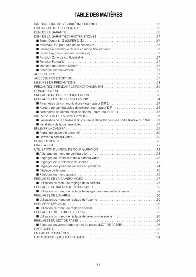
-61-
TABLE DES MATIÈRESINSTRUCTIONS DE SÉCURITÉ IMPORTANTES . . . . . . . . . . . . . . . . . . . . . . . . . . . . . . . . . .55LIMITATION DE RESPONSABILITÉ . . . . . . . . . . . . . . . . . . . . . . . . . . . . . . . . . . . . . . . . . . . .56DÉNI DE LA GARANTIE . . . . . . . . . . . . . . . . . . . . . . . . . . . . . . . . . . . . . . . . . . . . . . . . . . . . .56DÉNI DE LA GARANTIECARACTÉRISTIQUES . . . . . . . . . . . . . . . . . . . . . . . . . . . . . . . . . . .57
■ Super Dynamic 3 (SUPER-D 3) . . . . . . . . . . . . . . . . . . . . . . . . . . . . . . . . . . . . . . . . . . .57■ Nouveau DSP pour une haute sensibilité . . . . . . . . . . . . . . . . . . . . . . . . . . . . . . . . . . . . .57■ Passage automatique de nuit en mode Noir et blanc . . . . . . . . . . . . . . . . . . . . . . . . . . .57■ Digital Flip (retournement numérique) . . . . . . . . . . . . . . . . . . . . . . . . . . . . . . . . . . . . . . .57■ Fonction Zone de confidentialité . . . . . . . . . . . . . . . . . . . . . . . . . . . . . . . . . . . . . . . . . . .57■ Fonction Patrouille . . . . . . . . . . . . . . . . . . . . . . . . . . . . . . . . . . . . . . . . . . . . . . . . . . . . . .57■ Mémoire de position caméra . . . . . . . . . . . . . . . . . . . . . . . . . . . . . . . . . . . . . . . . . . . . . .57■ Détection de mouvement . . . . . . . . . . . . . . . . . . . . . . . . . . . . . . . . . . . . . . . . . . . . . . . . .57
ACCESSOIRES . . . . . . . . . . . . . . . . . . . . . . . . . . . . . . . . . . . . . . . . . . . . . . . . . . . . . . . . . . . .57ACCESSOIRES EN OPTION . . . . . . . . . . . . . . . . . . . . . . . . . . . . . . . . . . . . . . . . . . . . . . . . . .57MESURES DE PRÉCAUTIONS . . . . . . . . . . . . . . . . . . . . . . . . . . . . . . . . . . . . . . . . . . . . . . . .58PRÉCAUTIONS PENDANT LE FONCTIONNEMENT . . . . . . . . . . . . . . . . . . . . . . . . . . . . . . .59CONSTRUCTION . . . . . . . . . . . . . . . . . . . . . . . . . . . . . . . . . . . . . . . . . . . . . . . . . . . . . . . . . .62PRÉCAUTIONS POUR L’INSTALLATION . . . . . . . . . . . . . . . . . . . . . . . . . . . . . . . . . . . . . . . .63RÉGLAGES DES INTERRUPTEURS DIP . . . . . . . . . . . . . . . . . . . . . . . . . . . . . . . . . . . . . . . .64
■ Paramètres de communications (Interrupteur DIP 2) . . . . . . . . . . . . . . . . . . . . . . . . . . .64■ Numéro de caméra vidéo déterminé (Interrupteur DIP 1) . . . . . . . . . . . . . . . . . . . . . . . .65■ Paramètres de communication RS485 (Interrupteur DIP 1) . . . . . . . . . . . . . . . . . . . . . . .66
INSTALLATION DE LA CAMÉRA VIDÉO . . . . . . . . . . . . . . . . . . . . . . . . . . . . . . . . . . . . . . . .67■ Préparation de la caméra et du couvercle décoratif pour une sortie latérale du câble. . . .67■ Installation de la caméra vidéo . . . . . . . . . . . . . . . . . . . . . . . . . . . . . . . . . . . . . . . . . . . .67
ENLEVER LA CAMÉRA . . . . . . . . . . . . . . . . . . . . . . . . . . . . . . . . . . . . . . . . . . . . . . . . . . . . . .69■ Retrait du couvercle décoratif . . . . . . . . . . . . . . . . . . . . . . . . . . . . . . . . . . . . . . . . . . . . .69■ Enlever la caméra vidéo . . . . . . . . . . . . . . . . . . . . . . . . . . . . . . . . . . . . . . . . . . . . . . . . . .69
BRANCHEMENTS . . . . . . . . . . . . . . . . . . . . . . . . . . . . . . . . . . . . . . . . . . . . . . . . . . . . . . . . . .70RS485 AJUST . . . . . . . . . . . . . . . . . . . . . . . . . . . . . . . . . . . . . . . . . . . . . . . . . . . . . . . . . . . . .72UTILISATION DU MENU DE CONFIGURATION . . . . . . . . . . . . . . . . . . . . . . . . . . . . . . . . . .73
■ Affichage du menu de configuration . . . . . . . . . . . . . . . . . . . . . . . . . . . . . . . . . . . . . . . .73■ Réglages de l’identifiant de la caméra vidéo . . . . . . . . . . . . . . . . . . . . . . . . . . . . . . . . . .73■ Réglages de la sélection de scènes . . . . . . . . . . . . . . . . . . . . . . . . . . . . . . . . . . . . . . . .73■ Réglages des positions définies au préalable . . . . . . . . . . . . . . . . . . . . . . . . . . . . . . . . .74■ Réglage de langue . . . . . . . . . . . . . . . . . . . . . . . . . . . . . . . . . . . . . . . . . . . . . . . . . . . . . .76■ Réglages du menu avancé . . . . . . . . . . . . . . . . . . . . . . . . . . . . . . . . . . . . . . . . . . . . . . .76
RÉGLAGES DE LA CAMÉRA VIDÉO . . . . . . . . . . . . . . . . . . . . . . . . . . . . . . . . . . . . . . . . . . .77■ Utilisation du menu de réglage de la caméra . . . . . . . . . . . . . . . . . . . . . . . . . . . . . . . . .77
RÉGLAGES DE BALAYAGE PAN/AZIMUTH . . . . . . . . . . . . . . . . . . . . . . . . . . . . . . . . . . . . .82■ Utilisation du menu de réglage balayage panoramique/inclinaison . . . . . . . . . . . . . . . .82
RÉGLAGES DE L’ALARME . . . . . . . . . . . . . . . . . . . . . . . . . . . . . . . . . . . . . . . . . . . . . . . . . . .90■ Utilisation du menu de réglage de l’alarme . . . . . . . . . . . . . . . . . . . . . . . . . . . . . . . . . . .90
RÉGLAGES SPÉCIAUX . . . . . . . . . . . . . . . . . . . . . . . . . . . . . . . . . . . . . . . . . . . . . . . . . . . . .93■ Utilisation du menu de réglage spécial . . . . . . . . . . . . . . . . . . . . . . . . . . . . . . . . . . . . . .93
RÉGLAGE DE SÉLECTION DE SCÈNE . . . . . . . . . . . . . . . . . . . . . . . . . . . . . . . . . . . . . . . . .95■ Utilisation du menu de réglage de sélection de scène . . . . . . . . . . . . . . . . . . . . . . . . . .95
RÉGLAGES DU MOT DE PASSE . . . . . . . . . . . . . . . . . . . . . . . . . . . . . . . . . . . . . . . . . . . . . .96■ Réglages du verrouillage du mot de passe (MOT DE PASSE) . . . . . . . . . . . . . . . . . . . .96
RACCOURCIS . . . . . . . . . . . . . . . . . . . . . . . . . . . . . . . . . . . . . . . . . . . . . . . . . . . . . . . . . . . .98EN CAS DE PROBLÈMES . . . . . . . . . . . . . . . . . . . . . . . . . . . . . . . . . . . . . . . . . . . . . . . . . . .100CARACTÉRISTIQUES TECHNIQUES . . . . . . . . . . . . . . . . . . . . . . . . . . . . . . . . . . . . . . . . . .104
WV-CS954_FR 09.1.21 2:55 PM ページ61

-62-
CONSTRUCTION
Fonctionnement sans problème• Cette caméra vidéo utilise une "bague collectrice" pour la transmission de l'alimentation électrique et des signaux. Une
bague collectrice encrassée peut provoquer une détérioration de la qualité de l’image pendant le balayage ainsi que dubruit. Pour que la caméra fonctionne sans problème assurez-vous que la fonction nettoyage (voir page 89) est activée.
• Si le nettoyage de la bague collectrice ne suffit pas à améliorer la qualité d’image, cela voudrait dire que la baguecollectrice a atteint la fin de sa durée de fonctionnement. Demandez à un technicien ou à l’installateur système qualifiésde la remplacer.
L’objectif ne peut pas être remplacé.
Connecteur d’entrée d’alarme
Connecteur de sortie d’alarme
Connecteur de sortie vidéo
Port de transmission de données
Câble d’alimentation de la caméra
Base de fixation de la caméra
Fil de sécurité
Couvercle décoratif (fourni)
Bague de fixation du dômeCaméra
Couvercle du dôme
Retirez d’abord la caméra avant d’enlever le couvercle du dôme. (page 69)Faites pivoter la bague de fixation du dôme vers la gauche pour l’enlever.Serrez solidement la bague de fixation du dôme pour éviter qu’il se détache. Maintenez solidement la caméra lorsque vous retirez le couvercle du dôme.Le couvercle du dôme peut être facilement endommagé, il doit être manipulé avec soin.
Objectif
WV-CS954_FR 09.1.21 2:55 PM ページ62

-63-
Avertissement: Discutez de l’emplacement d’installationde la caméra avec votre détaillant et sélectionnez unemplacement pouvant soutenir l’installation. Si vousinstallez la caméra au plafond ou au mur, Panasonicne peut être tenu responsable des accidentsoccasionnés par la chute de la caméra suite à uneinstallation incorrecte (à l’exception des accidentsoccasionnés par la caméra elle-même). Soyez vigilantlors de l’installation de la caméra. Si l’installation n’estpas suffisamment stable, veillez à la renforcer demanière adaptée et à vous assurer qu’elle est sûre.
Avertissement: L’installation doit toujours être effectuéepar un technicien ou un installateur système qualifiés.Le manque de connaissances techniques entraîne unrisque d’incendie, d’électrocution, de blessures et dedommages matériels.
■ Emplacement et installation de la caméra• Fixez la camera sur un plafond (béton etc.) à un endroit
suffisamment solide pour la supporter. • Si vous installez la caméra vidéo sur un plafond peu solide
(comme un faux plafond), utilisez le support de fixationdirect au plafond WV-Q105 ou le support de fixationintégré WV-Q116, disponibles en option.
• Pour la fixation au plafond, utilisez le support plafond WV-Q117 disponible en option.
• Pour la fixation au mur, utilisez le support mural WV-Q118disponible en option.
■ Cette caméra est destinée à un usage en intérieur. Ellene doit pas servir à un usage en extérieur.
■ La caméra vidéo est uniquement prévue pour fonction-ner en position suspendue. Une utilisation verticale ouinclinée peut entraîner des dysfonctionnements etabréger la durée de vie de la caméra.
■ Installez la caméra en position horizontale, dôme pointévers le bas.
■ Ne jamais installer ou utiliser la caméra dans lesemplacements suivants.
• Lieux directement exposés à la pluie ou à l’eau.• A proximité d’une piscine ou d’endroits où des produits
chimiques sont utilisés.• Cuisines et autres lieux où de grandes quantités de
vapeur d’eau ou d’huiles sont dégagées, autres lieuxinflammables et autres environnements spécifiques.
• Endroits où des radiations, des rayons X, des champsmagnétiques forts sont générés.
• En mer, en bord de mer ou dans des endroits où des gazcorrosifs sont émis.
• Emplacements situé hors de la fourchette de températurede fonctionnement (-10 °C à +50 °C {14 °F - 112 °F}).
• Dans un véhicule à moteur, un bateau ou dans d’autreslieux soumis à de fortes vibrations (cette caméra vidéon’est pas destinée à une utilisation à bord d’un véhicule).
• A proximité d’une bouche d’aération, d’une porte quis'ouvre vers l'extérieur, ou tout autre endroit sujet à destempératures extrêmes (de telles conditions provoquent laformation de buée et de condensation sur le couvercle dudôme).
■ Les câbles de branchement de la caméra (alimentation,sortie vidéo, RS485, entré d’alarme, sortie d’alarme)peuvent sortir sur le côté ou sur le sommet de lacaméra.
• Pour une configuration de sortie supérieure de câble,faites un trou dans le plafond pour le passage des câbles.(Voir l’étape 3 page 67).
• Pour une configuration de sortie de câble latérale,préparer une ouverture dans le boîtier coulé et lecouvercle décoratif. (Voir page 67 "Préparation de lacaméra et du couvercle décoratif pour une sortie latéraledu câble.")
■ Questions relatives à des interférences de bruitSi vous utilisez un câble d’alimentation supérieur à 120 V CA,et un câblage supérieur à 1 mètre, il faut effectuer le câblageen utilisant un conduit métallique séparé. (Le conduitmétallique doit être relié à la terre).
■ Les vis doivent être commandées séparément.Des vis ne sont pas fournies avec la caméra video. Veillezà ce que tous les matériaux et la structure del'emplacement où la caméra sera installée, soient assezsolides pour supporter le poids total de l'appareil.
Important :• Avant de régler la caméra pour une configuration
dans laquelle son port de données RS485 est utilisépour le contrôle caméra (balayage, inclinaison) parun contrôleur de système, les interrupteurs DIPdoivent être configurés conformément au numérode caméra déterminé et aux paramètres decommunication. (page 64) Si la configuration DIP n’est pas effectuée, lecontrôle du contrôleur de système ne sera paspossible et le réglage de la caméra devra êtreeffectué à nouveau. Veillez à contrôler les réglagesde l’interrupteur DIP avant d’installer la caméra.
Remarques:• En cas de connexion à la terre, veillez à le faire avant de
brancher la prise d’alimentation principale. De même enenlevant la mise à la terre, veillez à débrancher la prised’alimentation principale.
• La caméra vidéo n’est pas équipée d’un commutateurd’alimentation, elle se met sous tension dès que lecâble d’alimentation est branché à la prise de courant.Une fonction d’autonettoyage est activés(PAN/AZIMUTH/ZOOM/FOCUS) lorsque la caméra estmise sous tension.
PRÉCAUTIONS POUR L’INSTALLATION
WV-CS954_FR 09.1.21 2:55 PM ページ63

-64-
■ Émission de chaleurLa surface de la caméra émet de la chaleur. Des trous deventilation devraient être prévus lors de l'installation de lacaméra dans un plafond ou un emplacement confiné oùde la chaleur peut monter.
■ Degré d’humidité élevé. Si la caméra est installée alors que le degré d’humidité est trèsélevé, de la buée risque de se former et d’embuer le dôme. Sile dôme s’embue, retirez-le lorsque l'humidité baisse etnettoyez la buée à l’intérieur de la caméra puis replacez-le.(page 59, 62)
Trous de ventilation
RÉGLAGES DES INTERRUPTEURS DIP
Pour une configuration dans laquelle le port de données RS485 de la caméra est utilisé pour le contrôle caméra (balayage,inclinaison etc.) par un contrôleur de système, les interrupteurs DIP doivent être configurés conformément au numéro decaméra déterminé et aux paramètres de communication. La base de fixation de la caméra doit être retirée pour accéder aux interrupteurs DIP Voir les étapes 1 et 2 à la page 67 pourdes informations sur la manière de démonter la base de fixation de la caméra.
1 2 3 41 2 3 4
ON(OUI) ON(OUI)
5 6 7 8
Interrupteur DIP 1 Interrupteur DIP 2
■ Paramètres de communications (Interrupteur DIP 2)Le réglage d'usine par défaut de ces interrupteurs DIP sont tous OFF.
Interrupteur 1: Terminateur (Résistance de la terminaison interne) Le régler sur ON dans les circonstances suivantes.• Lorsqu’une seule caméra vidéo est branchée. • Lorsqu’une seule caméra vidéo est branchée via une connexion en
guirlande sur une longue distance.
Interrupteurs 2 à 4 : Paramètres de communicationCe réglage alterne entre une communication à 2 ou à 4 lignes. Utilisez ces interrupteurs pour sélectionner le protocole decommunication en cours d’utilisation.
1 2 3 4
Terminateur
Paramètres de communication
ON(OUI)
1 2 3 4
Communication à 4 lignes
1 2 3 4
Communication bi-filaire
ON(OUI)ON(OUI)
WV-CS954_FR 09.1.21 2:55 PM ページ64

-65-
■ Numéro de caméra vidéo déterminé (Interrupteur DIP 1)Le réglage d'usine par défaut de ces interrupteurs DIP sont tous OFF. (Système coaxial multiplexe)
1 2 3 4 5 6 7 8
Interrupteur DIP 1Numéro de
caméra
1 2 3 4 5 6 7 8
1 2 3 4 5 6 7 8
1 2 3 4 5 6 7 8
1 2 3 4 5 6 7 8
1 2 3 4 5 6 7 8
1 2 3 4 5 6 7 8
1 2 3 4 5 6 7 8
1 2 3 4 5 6 7 8
1 2 3 4 5 6 7 8
1 2 3 4 5 6 7 8
1 2 3 4 5 6 7 8
1 2 3 4 5 6 7 8
1 2 3 4 5 6 7 8
1 2 3 4 5 6 7 8
1 2 3 4 5 6 7 8
1 2 3 4 5 6 7 8
1 2 3 4 5 6 7 8
1 2 3 4 5 6 7 8
1 2 3 4 5 6 7 8
1 2 3 4 5 6 7 8
1 2 3 4 5 6 7 8
1 2 3 4 5 6 7 8
1 2 3 4 5 6 7 8
1 2 3 4 5 6 7 8
1 2 3 4 5 6 7 8
1 2 3 4 5 6 7 8
1 2 3 4 5 6 7 8
1 2 3 4 5 6 7 8
1 2 3 4 5 6 7 8
1 2 3 4 5 6 7 8
1 2 3 4 5 6 7 8
Interrupteur DIP 1Numéro de
caméra Interrupteur DIP 1Numéro de
caméra
1 ~ 96 *
1
2
3
4
5
6
7
8
9
10
11
12
13
14
15
16
17
18
19
20
21
22
23
24
25
26
27
28
29
30
31
32
33
34
35
36
37
38
39
40
41
42
43
44
45
46
47
48
49
50
51
52
53
54
55
56
57
58
59
60
61
62
63
64
65
66
67
68
1 2 3 4 5 6 7 8
1 2 3 4 5 6 7 8
1 2 3 4 5 6 7 8
1 2 3 4 5 6 7 8
1 2 3 4 5 6 7 8
1 2 3 4 5 6 7 8
1 2 3 4 5 6 7 8
1 2 3 4 5 6 7 8
1 2 3 4 5 6 7 8
1 2 3 4 5 6 7 8
1 2 3 4 5 6 7 8
1 2 3 4 5 6 7 8
1 2 3 4 5 6 7 8
1 2 3 4 5 6 7 8
1 2 3 4 5 6 7 8
1 2 3 4 5 6 8
1 2 3 4 5 6 7 8
1 2 3 4 5 6 7 8
1 2 3 4 5 6 7 8
1 2 3 4 5 6 8
1 2 3 4 5 6 7 8
1 2 3 4 5 6 7 8
1 2 3 4 5 6 7 8
1 2 3 4 5 6 7 8
1 2 3 4 5 6 7 8
1 2 3 4 5 6 7 8
1 2 3 4 5 6 7 8
1 2 3 4 5 6 7 8
1 2 3 4 5 6 7 8
1 2 3 4 5 6 7 8
1 2 3 4 5 6 7 8
1 2 3 4 5 6 7 8
1 2 3 4 5 6 7 8
1 2 3 4 5 6 7 8
1 2 3 4 5 6 7 8
1 2 3 4 5 6 7 8
1 2 3 4 5 6 7 8
ON(OUI)
ON(OUI)
ON(OUI)
ON(OUI)
ON(OUI)
ON(OUI)
ON(OUI)
ON(OUI)
ON(OUI)
ON(OUI)
ON(OUI)
ON(OUI) ON(OUI)
ON(OUI)
ON(OUI)
ON(OUI)
ON(OUI)
ON(OUI)
ON(OUI)
ON(OUI)
ON(OUI)
ON(OUI)
ON(OUI)
ON(OUI)
ON(OUI)
ON(OUI)
ON(OUI)
ON(OUI)
ON(OUI)
ON(OUI)
ON(OUI)
ON(OUI)
ON(OUI)
ON(OUI)
ON(OUI)
ON(OUI)
ON(OUI)
ON(OUI)
ON(OUI)
ON(OUI)
ON(OUI)
ON(OUI)
ON(OUI)
ON(OUI)
ON(OUI)
ON(OUI)
ON(OUI)
ON(OUI)
ON(OUI)
ON(OUI)
ON(OUI)
ON(OUI)
ON(OUI)
ON(OUI)
ON(OUI)
ON(OUI)
ON(OUI)
ON(OUI)
ON(OUI)
ON(OUI)
ON(OUI)
ON(OUI)
ON(OUI)
ON(OUI)
ON(OUI)
ON(OUI)
ON(OUI)
ON(OUI)
ON(OUI)
7
7
WV-CS954_FR 09.1.21 2:55 PM ページ65

-66-
* Pour utiliser le réglage Numéro de caméra vidéo de 1 à 96 il faut configurer le réglage du numéro de la caméra à l’aide du menu RS485AJUST. Pour des détails sur la configuration de ce réglage, voir l’étape 2 et la page 72.
* Mettre sous tension alors que ce réglage est sélectionné déclenche l’affichage du menu RS485 AJUST pendant la routine d’initialisation.
1 2 3 4 5 6 7 8
Interrupteur DIP 1Numéro de
caméra
1 2 3 4 5 6 7 8
1 2 3 4 5 6 7 8
1 2 3 4 5 6 7 8
1 2 3 4 5 6 7 8
1 2 3 4 5 6 7 8
1 2 3 4 5 6 7 8
1 2 3 4 5 6 7 8
1 2 3 4 5 6 7 8
1 2 3 4 5 6 7 8
1 2 3 4 5 6 7 8
1 2 3 4 5 6 7 8
1 2 3 4 5 6 7 8
1 2 3 4 5 6 7 8
1 2 3 4 5 6 7 8
1 2 3 4 5 6 7 8
1 2 3 4 5 6 7 8
1 2 3 4 5 6 7 8
Interrupteur DIP 1Numéro de
caméra Interrupteur DIP 1Numéro de
caméra
69
70
71
72
73
74
75
76
77
78
79
80
81
82
83
84
85
86
87
88
89
90
91
92
93
94
95
1 2 3 4 5 6 7 8
1 2 3 4 5 6 7 8
1 2 3 4 5 6 7 8
1 2 3 4 5 6 7 8
1 2 3 4 5 6 7 8
1 2 3 4 5 6 7 8
1 2 3 4 5 6 7 8
1 2 3 4 5 6 7 8
1 2 3 4 5 6 7 8
ON(OUI)
ON(OUI)
ON(OUI)
ON(OUI)
ON(OUI)
ON(OUI)
ON(OUI)
ON(OUI)
ON(OUI)
ON(OUI)
ON(OUI)
ON(OUI)
ON(OUI)
ON(OUI)
ON(OUI)
ON(OUI)
ON(OUI)
ON(OUI)
ON(OUI)
ON(OUI)
ON(OUI)
ON(OUI)
ON(OUI)
ON(OUI)
ON(OUI)
ON(OUI)
ON(OUI)
■ Paramètres de communication RS485 (Interrupteur DIP 1)Le fait de configurer l’interrupteur DIP 1 de la manière indiquée ci-dessous réinitialise les paramètres de communication àleurs réglages par défaut d’usine. Vous pouvez changer ces réglages selon vos souhaits.
1 2 3 4 5 6 7 8
Interrupteur DIP 1 Description du réglage
1 2 3 4 5 6 7 8
1 2 3 4
ON
5 6 7 8
1 2 3 4 5 6 7 8
Ce réglage remet les paramètres de communication à leurs réglages par défaut d’usine.
VITESSE : 19 200 bits par seconde, DATA BIT : 8 bits, CONTR PARITE : NON, BIT DE STOP : 1 bit
VITESSE : 9 600 bits par seconde, DATA BIT : 8 bits, CONTR PARITE : NON, BIT DE STOP : 1 bit
VITESSE : 4 800 bits par seconde, DATA BIT : 8 bits, CONTR PARITE : NON, BIT DE STOP : 1 bitON(OUI)
ON(OUI)
ON(OUI)
ON(OUI)
Exécutez les étapes suivantes pour utiliser ce réglage.(1) Mettez la caméra vidéo hors tension et utilisez l’interrupteur DIP 1 pour configurer les paramètres de communication
RS485 comme indiqué ci-dessus.(2) Mettez la caméra vidéo sous tension.
Ceci a pour effet d’appliquer les paramètres configurés à l’étape (1). (3) Mettez la caméra hors tension, utilisez l’interrupteur DIP 1 pour régler le numéro de caméra (voir pages 65 et 66 puis
remettez la caméra sous tension.
WV-CS954_FR 09.1.21 2:55 PM ページ66

-67-
INSTALLATION DE LA CAMÉRA VIDÉO
■ Préparation de la caméra et du cou-vercle décoratif pour une sortielatérale du câble.
La caméra vidéo et le couvercle décoratif doivent êtrepréparés comme indiqué ci-dessous lors de l’installationde la caméra au plafond ou sur un mur, si ses câbles(alimentation, sortie vidéo, RS485, entrée d’alarme, sortied’alarme) sortent latéralement. La base de fixation de la caméra vidéo doit être retiréepour préparer la caméra. Voir les étapes 1 et 2 ci-dessouspour des informations sur la manière de retirer la base defixation de la caméra. * Pour éviter de rayer le dôme pendant que vous travaillez,
placez-le sur un tissu doux.
■ Installation de la caméra vidéo• Sélectionner un emplacement suffisamment robuste
pour supporter le poids total de la caméra. L’installersur un emplacement peu robuste peut entraîner sachute.
• Une fois le travail d’installation terminé, retirez la feuillede protection.
• Si vous utilisez un support en option pour installer lacaméra, installez le support selon les instructionsfournies.
1. Retirez la vis (M3 × 6) qui maintient la caméra sur sabase de fixation de la caméra. Mettez la vis de côté de manière à pouvoir la retrouverfacilement.
2. Faites pivoter la base de fixation de la caméra dans lesens indiqué par la flèche et retirez-la.
3. Utilisez la base de fixation de la caméra comme ungabarit pour repérer et marquer l’emplacement des 4points de fixation au plafond. Si vous utilisez la configuration de sortie supérieure decâble, marquez l’emplacement du trou du câble sur leplafond et percez le trou.
4. Posez la base de fixation de la caméra au plafond. Utilisez les vis (M4) aux emplacements que vous avezrepérés ci-dessus pour fixer solidement la base defixation de la caméra au plafond. Si vous ne prévoyez pas d’installer immédiatement lacaméra, placez sur la base de fixation de la caméra lafeuille de protection contre la poussière fournie avec lacaméra pour éviter qu’elle se salisse.
Cassez-le à l’aide d’une pince.
Coupez-le à l’aide d’une lame.
Préparation du boîtier moulé de la caméra vidéo*
Préparation du couvercle décoratif
Fixation de la vis
Après avoir desserré la vis, pressez la caméra vers le haut et ensuite retirez-la.
15°Faire pivoter Tirer la base de
fixation de la caméra vers le haut pour l’enlever.
Marquer ici
Vis (M4, disponibles séparément)
Feuille de protection contre la poussière (fourni avec la caméra)
WV-CS954_FR 09.1.21 2:55 PM ページ67

-68-
5. Installez le fil de sécurité pour maintenir la caméra sursa base de fixation de la caméra. Tirez sur le fil de sécurité pour vous assurer que sabague est solidement rattachée à la base de fixation. Si la feuille de protection contre la poussière fournieavec la caméra vidéo est mise sur la base de fixationde la caméra, retirez-la avant d'effectuer l’étape ci-dessus.
Remarque: Le fil de sécurité est conçu pour ysuspendre la caméra. Ne pas exercer sur le fil uneforce plus élevée que le poids de la caméra vidéo.
6. Installer la caméra sur la base de fixation de lacaméra. Alignez la caméra avec la base de fixation de lacaméra, appuyez au maximum sur la caméra puisfaites-la pivoter dans le sens indiqué par la flèche.
7. Utilisez la vis mise de côté à l’étape 1 pour visser lacaméra sur sa base de fixation de la caméra.
8. Vérifiez l'installation. • La caméra vidéo est-elle à niveau et solidemenet
installée ?• Y a-t-il un risque de relâchement de la fixation ? • Est-ce que la partie fixe de la caméra reste en place
quand vous essayez de la faire pivoter ?
9. Séparez les deux parties du couvercle décoratif (fourniavec la caméra). Poussez le couvercle décoratif vers le haut enappuyant sur les points indiqués (repérés par lesflèches, dans l’illustration ci-dessous) pour déboîter lesdeux parties l’une de l’autre.
* Pour enlever le couvercle décoratif, la direction àpresser ( ) est indiquée sur le côté du couvercle.
Attention: Si vous appuyez sur le mauvais côté ducouvercle décoratif vous risquez de l’endommager.
10. Placez les deux pièces du couvercle décoratif àgauche et à droite de la caméra et accrochez-lesensemble. Alignez les crochets et appuyez la pièce indiquée parla flèche ci-dessous pour l’emboîter sur l’autre.
11. Glissez le couvercle décoratif sur le plafond. • Dans le cas d’une configuration de sortie supérieure
de câble, glissez le couvercle décoratif et appuyez-lefermement contre le plafond.
• Dans le cas d’une configuration de sortie de câblelatérale, alignez la partie découpée du couvercledécoratif avec les câbles en le faisant glisser et en lepressant fermement contre le plafond.
➡
Bague du fil de sécurité
Faire pivoter
Base de fixation de la caméra
Caméra vidéo
15°
DécrocherArrière
Fixer solidement
AppuyerAppuyerAppuyer
Fixer solidementAppuyer
ArrièreAlignez le crochet
Tenir solidement
Tenir solidement
Appuyer Appuyer
Configuration de sortie supérieure de câble
Configuration de sortie de câble latérale
Alignez avec la découpe
WV-CS954_FR 09.1.21 2:55 PM ページ68

-69-
ENLEVER LA CAMÉRA
Attention: Pour enlever la caméra et son couvercledécoratif, veillez à effectuer scrupuleusement etfidèlement les étapes ci-dessous. Vous risquez,autrement, d’endommager la caméra vidéo.
■ Retrait du couvercle décoratifNotez que vous devez séparer les deux parties ducouvercle décoratif pour l'enlever. 1. Séparez les deux parties du couvercle décoratif.
Poussez le couvercle décoratif vers le haut enappuyant sur les points indiqués (repérés parles flèches, dans l’illustration ci-dessous) pour déboîterles deux parties l’une de l’autre.
* Pour enlever le couvercle décoratif, la direction àappuyer ( ) est indiquée sur le côté du couvercle.
■ Enlever la caméra vidéoLa caméra vidéo et sa base sont fixées par des vis. Celafournit un double ancrage ; pour retirer la caméra vousdevez suivre la procédure suivante. 1. Retirez la vis qui maintient la caméra sur sa base de
fixation de la caméra. Mettez la vis de côté de manière à pouvoir la retrouverfacilement.
2. Retirez la caméra de sa base de fixation de la caméra. Faites pivoter la caméra dans le sens indiqué par laflèche et retirez-la.
3. Retirez le fil de sécurité de la base de fixation de lacaméra.
➡
DécrocherArrière
Fixer solidement
AppuyerAppuyerAppuyer
Fixer solidementAppuyer
15°
Fixation de la vis
Après avoir desserré la vis, pressez la caméra vers le haut et ensuite retirez-la.
Faire pivoter
Base de fixation de la caméra
Caméra vidéo
WV-CS954_FR 09.1.21 2:55 PM ページ69

-70-
No. debroche Source d’alimentation
1
2
3
4
24 V Courant Alternatif LIVE
24 V Courant alternatif NEUTRAL
Mise à la terre
Non utilisé
BRANCHEMENTS
Câble Coaxial (5C-2V)*2
24 V CA Câble pour la caméra 24 V CA
Données port RS485
Câble d’alarme 8P (fourni)
Câble d’alarme PP (fourni)
Connecteur de sortie vidéo
Connecteur d’entrée d’alarme
Connecteur de sortie d’alarme
Câble à paires torsadées*1
(BNC)
(RJ-12)
T(B)T(A)R(B)R(A)
(RJ-12)
Vers le Sélecteur matriciel etc.
Vers la prise d’entrée vidéo (CAMERA IN)
Vers le détecteur, etc.
Vers sonnerie, dispositif d’affichage etc.
Données port RS485 Connecteur d’entrée d’alarme
Entrée d’alarme 1 (noir)
GND (marron)
Entrée d’alarme 2 (rouge)
GND (orange)
Entrée d’alarme 3 (jaune)
GND (bleu clair ou vert)
rouge
orange
jaune
vert
Entrée d’alarme 4 (bleu)
GND (violet)
Connecteur de sortie d’alarme
Sortie d’alarme 1 (Gris)
GND (blanc)
Sortie d’alarme 2 (rose)
GND (vert clair ou bleu clair)
Transmission de données
Réception de données
*1: Pour le câble à paires torsadées, utilisez un câble blindé de faible impédance au calibrageaméricain # 22 (0,33mm2).
*2: Maintenez la longueur totale du câble coaxial en-dessous 1 200 mètres (en cas de 5C-2V).*3: Assurez-vous de connecter le câble conducteur de terre à la terre.
Capacités entrée/sortie d’alarmeEntrée d’alarme: Entrée amplifiée 5 V CC Capacité
d’excitation requise d’au moins 0,2 mA. OFF : 4 V CC minimum 5 V CC maximum,
ou ouvert OUI : 1 V CC maximum or court circuit
Sortie d’alarme: Sortie collecteur ouvert. 16 V CC,capacité d’excitation maximum 100 mA
OFF : OuvertOUI : 100 mA maximum
* Lors d’une connexion à un dispositif externe, configurezle système de manière à ne pas dépasser les capacités.
Remarque: Ne mettez pas la caméra hors tension dansles 30 secondes qui suivent sa mise sous tension. Sinon lebalayage panoramique, l’inclinaison, le zooming, ou lamise au point risquent de se dérégler.
Mesures de précautions• Les branchements suivants doivent être exécutés par un dépanneur ou un installateur système qualifiés en conformité
avec les codes locaux en vigueur. • Voir le verso de la page de couverture pour le branchement des fils de connexion.
#24(0,22mm2)
Calibre des fils decuivre (AWG)
Longueurde câble(approx.)
(m)
(pd.)
#22(0,33mm2)
#20(0,52mm2)
#18(0,83mm2)
20 30 45 75
65 100 160 260
1
3
2
4
• Connexion d’alimentation en courant alternatif de 24 V
Calibres recommandés des fils de connexion pour unealimentation en courant alternatif 24 V.
Informations relatives aux connecteurs accessoires
WV-CS954_FR 09.1.21 2:55 PM ページ70
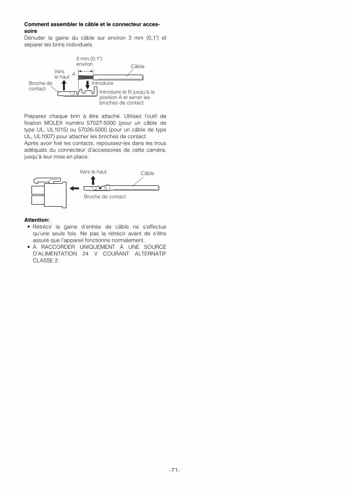
-71-
Broche de contact
Introduire
Vers le haut A
3 mm {0,1"} environ Câble
Introduire le fil jusqu'à la position A et serrer les broches de contact.
Broche de contact
Vers le haut Câble
Comment assembler le câble et le connecteur acces-soireDénuder la gaine du câble sur environ 3 mm {0,1"} etséparer les brins individuels.
Préparez chaque brin à être attaché. Utilisez l’outil defixation MOLEX numéro 57027-5000 (pour un câble detype UL, UL1015) ou 57026-5000 (pour un câble de typeUL, UL1007) pour attacher les broches de contact.Après avoir fixé les contacts, repoussez-les dans les trousadéquats du connecteur d’accessoires de cette caméra,jusqu’à leur mise en place.
Attention:• Rétrécir la gaine d’entrée de câble ne s’effectue
qu’une seule fois. Ne pas la rétrécir avant de s’êtreassuré que l’appareil fonctionne normalement.
• À RACCORDER UNIQUEMENT À UNE SOURCED’ALIMENTATION 24 V COURANT ALTERNATIFCLASSE 2.
WV-CS954_FR 09.1.21 2:55 PM ページ71

RS485 AJUST
Le paramétrage d’origine affiche l’écran du menu enlangue anglaise. Après avoir sélectionné le français dansle menu de réglage de langue (page 76), effectuez leparamétrage du RS485.La procédure suivante permet de configurer le réglage deRS485 lors de l’utilisation du contrôleur du système dansle cadre du contrôle de la caméra vidéo (balayagepanoramique, inclinaison, etc.) via son port detransmission de données.
1. Affichez le menu de configuration (voir page 73),amenez le curseur jusqu’à COMMUNICATION O etappuyez ensuite sur le bouton CAM (SET).Ceci a pour effet d’afficher le menu de configuration duRS485.
2. Vérifier le numéro de la caméra. (page 65)Le paramètre NUMERO UNITE affiche le numéro decaméral spécifié par l'interrupteur DIP 1. Le numéro decaméra par défaut est 1.Si l’interrupteur DIP 1 indique 1 à 96 comme le numérode caméra, amenez le curseur sur NUMERO UNITEpuis inclinez à gauche ou à droite la manette deréglage tous azimuts pour sélectionner un numéro decaméra (1 à 96).
Remarque: Il n’est pas nécessaire de configurer leréglage SOUS ADRESSE du menu RS485 AJUST.
3. Amenez le curseur sur VITESSE puis inclinez lamanette de réglage tous azimuts à gauche ou à droitepour sélectionner un réglage de vitesse detransmission. L’inclinaison de la manette de réglage tous azimuts faitdérouler l’affichage de la vitesse de transmissioncomme indiqué ci-dessous. (unité : bits/s) Le réglaged’usine par défaut est 19200.
4. Amenez le curseur sur DATA BIT puis inclinez lamanette de réglage tous azimuts à gauche ou à droitepour sélectionner un réglage de bit d’information (7 ou8). Le réglage d’usine par défaut est 8.
5. Amenez le curseur sur CONTR PARITE puis inclinez lamanette de réglage tous azimuts à gauche ou à droitepour sélectionner un réglage de contrôle de parité(NON, IMPAIR, PAIR). Le réglage d’usine par défaut est NON.
6. Amenez le curseur sur BIT DE STOP puis inclinez lamanette de réglage tous azimuts à gauche ou à droitepour sélectionner réglage de bit d’arrêt (1 ou 2). Le réglage d’usine par défaut est 1.
7. Amenez le curseur sur XON/XOFF puis inclinez lamanette de réglage tous azimuts à gauche ou à droitepour sélectionner un réglage XON/XOFF. Le réglage d’usine par défaut est NON UTILE. NON UTILE : Désactive le contrôle de flux de
données X ON/X OFF. UTILISE : Active le contrôle de flux de données X
ON/X OFF.8. Amenez le curseur sur TEMPS ATTENTE puis inclinez
la manette de réglage tous azimuts à gauche ou àdroite pour sélectionner un réglage de durée d’attente. La durée d’attente est le temps pendant lequel lacaméra devrait attendre avant de renvoyer lesdonnées quand aucun accusé de réception (ACK)n’est retourné après l’envoi des données. L’inclinaison de la manette de réglage tous azimuts faitdérouler l’affichage du temps d’attente dans l’ordreindiqué ci-dessous. (unité : ms) Le réglage d’usine pardéfaut est OFF.
9. Amenez le curseur sur DATA ALARME puis inclinez lamanette de réglage tous azimuts à gauche ou à droitepour sélectionner un réglage de mode d’envoi dedonnées d’alarme.SONDAGE : Envoie des données d’alarme en
réponse à une demande du contrôleurde système.
AUTO1 : Envoie des données d’alarme chaquefois qu'un signal d'alarme est reçu.
AUTO2 : Envoie des données d’alarme à 5secondes d’intervalles. C’est le réglaged’usine par défaut.
10. Amenez le curseur sur DELAI puis inclinez la manettede réglage tous azimuts à gauche ou à droite poursélectionner un réglage de temporisation.La temporisation est le délai d’attente de la caméraavant qu’elle envoie un accusé de réception (ACK).L’affichage de la temporisation change selon l’ordre ci-dessous. (unité : ms) Le réglage d’usine par défaut estOFF.
Ce réglage ne peut être configuré que si uneconfiguration bi-filaire est sélectionnée parl’interrupteur DIP 2 (voir page 64).
-72-
**RS485 AJUST**NUMERO UNITE 1SOUS ADRESSE -----VITESSE 19200DATA BIT 8CONTR PARITE NONBIT DE STOP 1XON/XOFF NON UTILETEMPS ATTENTE OFFDATA ALARME AUTO2DELAI OFF RET PRI
2400 4800 9600 19200
OFF ↔ 100MS ↔ 200MS ↔ 400MS ↔ 1000MS
OFF ↔ 100MS
WV-CS954_FR 09.1.21 2:55 PM ページ72

UTILISATION DU MENU DE CONFIGURATION
Ce mode d’emploi décrit les procédures defonctionnement du contrôleur de système WV-CU650.Le paramétrage d’origine affiche l’écran de menu enlangue anglaise. Après avoir sélectionné le français dansle menu de réglage de langue (page 76), effectuez lesopérations de paramétrage.Toutes les procédures de configuration de réglagescommencent depuis ce menu. Cette section expliquecomment afficher le menu de configuration et donne tousles détails concernant les éléments qu’il contient.
■ Affichage du menu de configuration
● Pour le WV-CU650(1) Sélectionner la caméra vidéo et l’écran sur lequel le
menu de configuration doit être affiché.(2) Appuyez sur le bouton MENU pour afficher LCD
MENU CAM 101.(3) Appuyez sur le bouton ENTER ou CAM (SET) pour
afficher CAMERA AJUST. (4) Appuyez sur le bouton F1.
Se reporter aux pages ci-dessous pour plus de détails.
q CAMÉRA ID Réglages de l’identifiant de lacaméra vidéo Cette page
w SELECT SCENE Réglages de sélection descène Cette page
e PREPO POSI Réglages des positionsdéfinies au préalable Page 74
r LANGUAGE Réglage de languePage 76
t AJUST AVANCE Réglages du menu avancéPage 76
■ Réglages de l’identifiant de la caméravidéoL’identification de la caméra est une série de caractèresalphanumériques qui indiquent l’emplacement de lacaméra. Ce paramètre peut être utilisé pour activer oudésactiver l’affichage de l’ID de la caméra sur lemoniteur et pour saisir l’ID de la caméra.
1. Amenez le curseur sur CAMÉRA ID puis inclinez lamanette de réglages tous azimuts à gauche ou à droitepour afficher ou non l'ID de caméra.
2. Sélectionnez OUI ou OFF et appuyez ensuite sur lebouton CAM (SET). Par défaut, le réglage estdésactivé.
3. Servez-vous de la manette de réglage tous azimutspour amenez le curseur sur le caractère souhaité etappuyez ensuite sur le bouton CAM (SET). Le caractère sélectionné apparaît alors dans la zonede saisie d’ID de caméra. Répétez l’étape 3 autant defois qu’il le faut pour saisir tous les caractères de l’IDde caméra. (Exemple : DOOR)
Pour saisir un espaceAmenez le curseur sur ESPACE et appuyez ensuite surle bouton CAM (SET). Pour effacer tous les caractères déjà saisisAmenez le curseur sur RESET et appuyez ensuite surle bouton CAM (SET). Pour modifier des caractères déjà saisisUtilisez la manette de réglage tous azimuts pouramener le curseur dans la zone de saisie d’ID decaméra. Inclinez ensuite la manette à droite ou agauche pour déplacer le ↑ pointeur sur le caractère àmodifier. Enfin, répétez l’étape 3 pour saisir unnouveau caractère.
4. Amenez le curseur sur POSI et appuyez ensuite sur lebouton CAM (SET). Ceci a pour effet d’afficher le menu de réglage de laposition d’affichage de l’ID.
5. Utilisez la manette pour sélectionner une positiond’affichage d’identification de la caméra et appuyezensuite sur le bouton MON (ESC). L’enregistrement de la position d’affichage d’identificationde la caméra est effectué et le menu de réglage de lacaméra s’affiche.
■ Réglages de la sélection de scènesAffichez le menu de sélection de scène à partir du menude configuration pour configurer les réglages de sélectionde scène. Affichez d’abord le menu de réglage desélection de scène. 1. Affichez le menu de configuration (cette page),
amenez le curseur jusqu’à SELECT SCENE O etappuyez ensuite sur le bouton CAM (SET). Ceci permet d’afficher le menu de configuration desélection de scène.
-73-
MODELE WV-CS954
CAMÉRA ID OFF∫SELECT SCENE∫PREPO POSI∫LANGUAGE∫
∑AJUST AVANCE
q
e
t
w
r
CAMÉRA ID--- 0123456789 ABCDEFGHIJKLM NOPQRSTUVWXYZ ().,'":;&#!?= +-*/%$
ESPACE ----- POSI RET RESET
DOOR··········· ≤
DOOR
Zone de saisie d’ID de caméra
**SELECT SCENE**
SCENE INTERIEUR(-)
CHARGEMENT RET PRI
WV-CS954_FR 09.1.21 2:55 PM ページ73

Remarques:• Un astérisque (*) à la droite d’un numéro de position
indique qu’il a déjà une position préréglée qui lui a étéassignée. Le numéro de position d’origine est signalé par la lettre Hà côté de l’astérisque.
• Lorque le curseur est situé sur un numéro de position quipossède une position d’identification, le texte de laposition d’identification s’affiche à côté de l’ID : sur l’écrande menu.
● Paramétrage de positionnement(REGLAGE POSI)
Le paramétrage de positionnement peut être utilisé pourspécifier la position de la caméra vidéo (balayagepanoramique et inclinaison), les réglages de zoom et de miseau point. 1. Amenez le curseur sur REGLAGE POSI O et appuyez sur
le bouton CAM (SET) pour afficher le menu deparamétrage de positionnement.
2. Amenez le curseur sur → BOUTON SET à droite dePAN/AZIMUTH, et appuyez ensuite sur le bouton CAM(SET) pour afficher le menu de réglage de balayagePAN/AZIMUTH.
3. Positionnez la caméra à l’aide de la manette deréglage tous azimuts et appuyez ensuite sur le boutonCAM (SET).
● Réglages de sélection de scèneUtilisez les procédures suivantes pour configurer lesréglages de sélection de scène. 1. Amenez le curseur sur SCENE puis inclinez la manette
de réglage tous azimuts à gauche ou à droite pourmodifier la configuration de scène.INTERIEUR (-) : Réglage pour l’intérieur (priorité à la
qualité de l’image)INTERIEUR (+) : Réglage pour l’intérieur (priorité à la
sensibilité)EXTERIEUR (-) : Réglage pour l’extérieur (priorité à
la qualité de l’image)EXTERIEUR (+) : Réglage pour l’extérieur (priorité à
la sensibilité).
Les réglages concernant l’image changent selon lesréglages de scène. Les réglages de sélection descène et les rapports avec les autres réglages sontmontrés dans le tableau ci-dessous.
2. Amenez le curseur sur CHARGEMENT et appuyezensuite sur le bouton CAM (SET). Ceci a pour effet d’appliquer à l’image la configurationque vous avez sélectionnée pour SCENE à l’étape 1.
■ Réglages des positions définies aupréalable
● Sélection du numéro de position (TABLE)Pour sélectionner un numéro de position, vous pouvez utiliserle paramètre TABLE du menu de réglage de balayagepanoramique/inclinaison au lieu du paramètre PREPO. 1. Amenez le curseur sur PREPO POSI O et appuyez ensuite
sur le bouton CAM (SET).
2. Amenez le curseur sur le numéro souhaité et appuyezensuite sur le bouton CAM (SET). Ceci a pour effet d’enregistrer le réglage de numéro deposition et d’afficher le menu de réglage de préréglage.(cette page) Pour sélectionner un numéro de position dans lafourchette de 033 à 064, amenez le curseur sur 33-64dans le coin inférieur gauche du menu puis appuyez sur lebouton CAM (SET). Les numéros préréglés configurés à lasuite sont les mêmes.
-74-
CAG VISION NUIT SHUTTER
INTERIEUR (-) MOYEN OFF OFF
INTERIEUR (+) ELEVE ×2 AUTO OFF
EXTERIEUR (-) MOYEN OFF AUTO
EXTERIEUR (+) ELEVE ×2 AUTO AUTO
NB RÉDUCT BRUIT BAL BLC
INTERIEUR (-) OFF BAS BAL BLC PERM1
INTERIEUR (+) OFF ÉLEVÉ BAL BLC PERM1
EXTERIEUR (-) AUTO BAS BAL BLC PERM2
EXTERIEUR (+) AUTO ÉLEVÉ BAL BLC PERM2
**PREPO POSI** 1* 2 3 4 5 6 7 8 9 10 11 12 13 14 15 16 17 18 19 20 21 22 23 24 25 26 27 28 29 30 31 32 ID:DOOR 033-064 225-256 RET PRI
**PREPO POSI** 33 34 35 36 37 38 39 40 41 42 43 44 45 46 47 48 49 50 51 52 53 54 55 56 57 58 59 60 61 62 63 64 ID: 065-096 001-032 RET PRI
PREPO NO. 1*REGLAGE POSI∫PRÉPO ID OUI∫
RET PRI SUPPRIMER
**POSI 1 **PAN/AZIMUTH ∑BOUTON SETZOOM/FOCUS ∑BOUTON SET
H AZIMUTH B/G PAN D
AJUST FIN PAN ∂ 0 ∑
RET PRI FLOOR1 DOOR
**POSI 1 **PAN/AZIMUTH ∑BOUTON SETZOOM/FOCUS ∑BOUTON SET
AJUST FIN PAN ∂ 0 ∑
RET PRI FLOOR1 DOOR
WV-CS954_FR 09.1.21 2:55 PM ページ74

1. Alignez le curseur “AJUST FIN PAN” avec les flèches← ou → et appuyez sur la touche SET pour régler lavaleur de décalage. Réglez la valeur de décalage à0,0 ou sur échelle de -10 à +10. Toutes les positionspréréglées de la position de la caméra sont ajustéesen fonction de la valeur de décalage.
Important: Données non compatibles avec les camérasexistantes. La télétransmission (upload) d’informations deparamétrage de caméras existantes, endommagera lesdonnées de la caméra. Si les données de la caméra sontendommagées, téléchargez (download) les informationsde réglage d’une caméra qui possède encore sesréglages par défaut d’usine puis télétransmettez-les(upload) vers la caméra dont les données sontendommagées.
● Préréglage d’identification (PRÉPO ID)L’identification préréglée de la caméra est une série decaractères alphanumériques qui indiquent l’emplacementde la caméra. Ce paramètre peut être utilisé pour activerou désactiver l’affichage de l’ID préréglée sur le moniteuret pour saisir l’ID préréglée. 1. Amenez le curseur sur PRÉPO ID puis inclinez la
manette de réglages tous azimuts à gauche ou à droitepour activer ou non l'ID préréglée.
2. Sélectionnez OUI ou OFF et appuyez ensuite sur lebouton CAM (SET). Ceci a pour effet d'afficher le menu de réglage de l’IDpréréglée.
3. Servez-vous de la manette de réglage tous azimutspour amenez le curseur sur le caractère souhaité etappuyez ensuite sur le bouton CAM (SET). La procédure de saisie de texte est la même que pourla saisie de l’ID de caméra. Voir les étapes 3 à 5 de “(1) Identification de la caméra(CAMÉRA ID)” page 73 pour des détails sur la saisiede texte pour l’ID préréglée et pour spécifier saposition sur l’écran.
Comment copier une ID préréglée de caméra vidéopréréglée à une autre positionAmenez le curseur sur COPIE et appuyez ensuite surle bouton CAM (SET). Cela affiche l’ID préréglée de laposition qui précède celle que vous êtes en train deparamétrer. Chaque pression de le bouton CAM (SET)fait défiler le numéro de position qui précède et afficheson identification préréglée.
4. Amenez le curseur sur → BOUTON SET à droite deZOOM/FOCUS, et appuyez ensuite sur le bouton CAM(SET) pour afficher le menu de réglage de ZOOM/FOCUS.
5. Déplacez la manette de réglage à gauche, à droite, enhaut et en bas pour ajuster la position de la mise aupoint et appuyez ensuite sur le bouton CAM (SET).
Remarques :• La mise au point peut s’avérer difficile lorsque la caméra
vidéo est à un angle proche de l’horizontale en raison de ladéformation créée par la courbe du couvercle du dôme.
• Un numéro de position différent peut être sélectionné enamenant le curseur sur le numéro de position au haut dumenu de paramétrage du positionnement et en inclinant lamanette de réglage à gauche et à droite. Le fait d’appuyersur le bouton CAM (SET) modifie l’écran de réglage pourle numéro de position nouvellement sélectionné.
• L’identification de la caméra vidéo et le préréglaged’identification mémorisés en cours, s’affichent en basdu menu de paramétrage de position.
• Lorsque vous utilisez un dispositif système autre que leWV-CU650/CU950*, WJ-HD309A/HD316A il est impossiblede paramétrer plus de 65 numéros de position. (à partir deJanvier 2006)* Les procédures de commande peuvent varier selon
la version logicielle du contrôleur de système. Pour la Ver.1.xx ou antérieure, seules les commandesde fonction de caméra video sont prises en charge.Pour la Ver.2.xx ou ultérieure, les touches boutonPRESET/PGM PRESET sont également prises en charge.
● Réglage de la position de la caméra enchangeant de caméra (AJUST FIN PAN)
Le contrôleur système etc. possède une fonction detéléchargement (sauvegarde) et télétransmission(récupération) des paramètres de réglage de la caméravidéo. Cette fonction vous permet de récupérer desinformations de paramétrages d'origine qui avaient étésauvegardées avant qu'un incident ou un dommageimprévu ait provoqué la perte des réglages de la caméra.Quand la caméra est changée il se peut, cependant, qu’ily ait de légères différences d’images entre les imagesd’origine et les images récupérées. La fonction “AJUSTFIN PAN” sert à ajuster ces différences.
-75-
**POSI 1 **PAN/AZIMUTH ∑BOUTON SETZOOM/FOCUS ∑BOUTON SET H ZOOM B/G FOCUS D
AJUST FIN PAN ∂ 0 ∑ RET PRI FLOOR DOOR
PREPO NO. 1*REGLAGE POSI∫PRÉPO ID OUI∫
RET PRI SUPPRIMER
**POSI 1* **PAN/AZIMUTH ∑BOUTON SETZOOM/FOCUS ∑BOUTON SET
AJUST FIN PAN ∂ 0 ∑
RET PRI FLOOR1 DOOR
Alignez le curseur ici.
PREPO NO. 1* 0123456789 ABCDEFGHIJKLM NOPQRSTUVWXYZ ().,'":;&#!?= +-*/%$ ESPACE COPIE POSI RET RESET
DOOR············ ≤
WV-CS954_FR 09.1.21 2:55 PM ページ75

■ Réglages du menu avancéLe menu de configuration avancée peut être affiché àpartir du menu de configuration.1. Affichez le menu de configuration (voir page 73),
amenez le curseur jusqu’à → AJUST AVANCE etappuyez ensuite sur le bouton CAM (SET).Le menu de configuration avancée apparaît alors.
TOUS les éléments peuvent être définis au niveau dumenu de configuration avancée.Pour retourner au menu de configuration rapide à partirdu menu détaillé, placer le curseur sur → AJUSTRAPIDE et appuyer sur le bouton CAM (SET).
Voir les pages ci-dessous pour des détails sur lesparamètres du menu de réglage.
q CAMÉRA Configuration de la caméravidéo Page 77
w PAN/AZIMUTH Réglages de balayagepanoramique et Inclinaison
Page 82e ALARME Réglages de l’alarme Page 90r SPECIAL Réglages spéciaux Page 93t COMMUNICATION* Réglages de communication
Page 72y SELECT SCENE Réglages de sélection de
scène Page 73u LANGUAGE Réglage de langue
Cette pagei AJUST RAPIDE Réglages du menu rapide
Page 73o MOT DE PASSE Réglage de mot de passe
Page 96
* Ce paramètre s’affiche uniquement si les réglages deRS485 sont configurés avec les interrupteurs DIP.
-76-
MODELE WV-CS954CAMÉRA∫PAN/AZIMUTH∫ALARME∫SPECIAL∫COMMUNICATION∫SELECT SCENE∫LANGUAGE∫
∑AJUST RAPIDEMOT DE PASSE OFF∫
q
e
t
u
o
w
r
y
i
■ Réglage de langue1. Amenez le curseur sur LANGUAGE O et appuyez
ensuite sur le bouton CAM (SET). 2. Sur le menu de sélection de 8 langues qui s’affiche,
sélectionnez la langue souhaitée. Par défaut, le réglage est anglais.
* Tous les écrans d’exemple de ce mode d’emploiaffichent des messages en anglais.
3. Amenez le curseur sur SET et appuyez ensuite sur lebouton CAM (SET). Quand vous changez de langue, le mot de passe etles titres sont effacés.
* L’élément configuré clignote lorsque la langue est encours de modification et il s’arrête de clignoter quand lalangue est changée. Ne faites pas fonctionner lecontrôleur du système lorsque vous modifiez lesréglages.
* Si vous sélectionnez la langue japonaise ou chinoise,seuls les identifiants et les titres s’affichent en katakanaou en chinois.
* L’affichage "LANGUAGE" reste en anglais même si leréglage de langue est modifié.
WV-CS954_FR 09.1.21 2:55 PM ページ76

RÉGLAGES DE LA CAMÉRA VIDÉO
■ Utilisation du menu de réglage de lacaméra
Afficher le menu de configuration de la caméra vidéo àpartir du menu de configuration (menu avancé) demanière à configurer les réglages de la caméra vidéo(page 76).1. Affichez le menu de configuration (voir page 76),
amenez le curseur jusqu’à CAMÉRA O et appuyezensuite sur le bouton CAM (SET). Ceci a pour effet d’afficher le menu de réglage de lacaméra.
* Les sections suivantes numérotées de q à !3expliquent l’utilisation de chaque paramètre du menude réglage de la caméra.
(1) Identification de la caméra (CAMÉRA ID)Voir la page 73 pour plus d’informations au sujet de laméthode de réglage de l’identifiant de la caméra vidéo.Par défaut, le réglage est désactivé.
(2) Contrôle de lumière (ALC/MANUEL)1. Amenez le curseur sur ALC/MANUEL puis inclinez la
manette de réglage tous azimuts à gauche ou à droitepour basculer entre ALC et MANUEL. ALC : Active l’ajustement automatique du
diaphragme pour l’adapter à la luminositédu sujet. Sélectionnez cet ALC en utilisantSUPER-D 3. Il s’agit du réglage pardéfaut.
MANUEL : Réglez le diaphragme à l’aide du boutonIRIS sur le contrôleur de système. Fixe lediaphragme.
Remarque: Le menu secondaire de compensationd’éclairage de contre-jour associé à ce menu est décritséparément et doit être configuré après avoir installé lacaméra vidéo dans son emplacement définitif et danssa position d’observation réelle.
2. Si ALC est réglé à l’étape 1, appuyez sur le boutonCAM (SET) pour régler SUPER-D3.
SUPER-D 33 (Super Dynamique 33)En cas de grande variation entre l’illumination du sujet etdes zones sombres de l’emplacement surveillé, la caméraajuste l’objectif en fonction des zones lumineuses. Il enrésulte une perte de détails dans les zones sombres. Aucontraire l’ajustement de la luminosité de l’objectif enfonction des zones sombres, fait que les zoneslumineuses deviennent pâles. SUPER-D 3 combinenumériquement une image configurée pour une visionnette des zones lumineuses avec une image configuréepour une vision nette des zones sombres créant ainsi uneimage finale qui préserve l’ensemble des détails.
Remarques:• SUPER-D 3 est uniquement pris en charge lorsque
ALC est sélectionné pour le contrôle de lumière(ALC/MANUEL).
• Les réglages de la caméra vidéo sont limités à ce quisuit lorsque SUPER-D 3 est activé.
SHUTTER (OBTURATEUR): OFF, AUTO (page 78) VISION NUIT: OFF, AUTO (page 78)
• Si les conditions de luminosité entraînent l’un desphénomènes suivants, désactivez SUPER-D 3. (1) Scintillement de l’écran ou couleur anormale (2) Bruit numérique dans les zones lumineuses de l’écran.
3. Amenez le curseur sur SUPER-D3 puis inclinez lamanette de réglage tous azimuts à gauche ou à droitepour basculer entre Oui et Off. OUI : Active SUPER-D 3 (Allez à l’étape 6)OFF : Désactive SUPER-D 3 (Allez à l’étape 4).
Il s’agit du réglage par défaut.
4. Amenez le curseur sur REGLAGE MASQUE O etappuyez ensuite sur le bouton CAM (SET). Cela a pour effet d’afficher l’écran de zone demasquage, avec le curseur sur la cellule supérieuregauche.
-77-
**CAMERA AJUST** 1/2CAMÉRA ID OFF∫ALC/MANUEL ALC∫SHUTTER AUTOCAG OUI(MOYEN)VISION NUIT OFFSYNC INTBAL BLC BAL BLC PERM1∫RÉDUCT BRUIT BASRÉSOLUTION ÉLEVÉMODE NB∫MODE AF AUTO L
**CAMERA AJUST** 2/2LIMITE ZOOM ×30STABILISATEUR OFF
RET PRI
q
e
t
u
o
!1
w
r
y
i
!0
!2!3
Perte de détail dans les zones sombres…
Zones lumineuses pâles…
Deux images combinées numériquement pour créer une image finale nette.
**CONTRÔLE ALC** CONTRE-JOUR
SUPER-D3 OFF
REGLAGE MASQUE∫
NIVEAU •I••••• 64 - +
RET PRI
WV-CS954_FR 09.1.21 2:55 PM ページ77

-78-
5. Masquez les cellules dans la zone où la lumière decontre jour est vive. Le fait de masquer une zone faitque son niveau de luminosité est ignoré. Exécutez les étapes suivantes pour effectuer unmasquage. (1) Inclinez la manette de réglage vers le haut et vers
le bas ainsi que vers la gauche et vers la droitepour amener le curseur sur la cellule que voussouhaitez masquer.
(2) Appuyez sur le bouton CAM (SET) pour masquer lacellule. Si vous amenez le curseur sur une cellule déjàmasquée, le motif clignotant du curseur alterneentre rayures horizontales et blanches. Le fait d’appuyer sur le bouton CAM (SET) lorsquele curseur est sur l’emplacement d’une cellulemasquée, annule son masquage. Pour annuler toutes les zones de masquage,appuyez sur le bouton F3.
(3) Après avoir masqué toutes les cellules souhaitées,appuyez sur le bouton MON (ESC) pour retournerau menu CONTRÔLE ALC de l’étape 1.
6. Amenez le curseur sur NIVEAU puis inclinez la manettede réglage tout azimuts à droite et à gauche pourajuster le niveau de sortie de l’image (contraste del’image). Si vous aviez sélectionné OUI à l’étape 3 de cetteprocédure, de meilleurs résultats seront obtenus enétablissant un contraste relativement élevé. Cependantun niveau de contraste trop élevé risqué d’augmenterla tendance à la rémanence d’images et au bruit.
Remarque: Si une manipulation de la touche ducontrôleur de système d’IRIS (OUV, FERMER)intervient après fermeture du menu, le niveau(NIVEAU) du menu CAMÉRA est répercuté etsauvegardé pour ces réglages. Cependant si lacaméra vidéo est sur une position préréglée, il estrépercuté en tant que paramètre de la positionpréréglée. Pour retourner au niveau initial par défaut,lancez la réinitialisation du diaphragme du contrôleurde système.
(3) Vitesse d’obturation (SHUTTER) 1. Amenez le curseur sur SHUTTER puis inclinez la
manette de réglage tous azimuts à gauche ou à droitepour sélectionner un réglage de vitesse d’obturation. L’inclinaison de la manette de réglage tous azimuts faitdérouler l’affichage des réglages de vitessed’obturation dans l’ordre indiqué ci-dessous. (unité :sec)
Si SUPER-D 33 est désactivé
Si SUPER-D 33 est activé
AUTO: Ce paramètre permet, par déplacementautomatique de l’obturateur lorsque cela estnécessaire, d’obtenir une image plus claired’objets extrêmement lumineux en extérieur,etc. Il s’agit du réglage par défaut.
OFF : réglé sur 1/60 seconde.
Remarques:• Lorsqu’AUTO est sélectionné pour le réglage de
l’obturateur, la lumière fluorescente risque deprovoquer des scintillements sur l'image. Si cela seproduit, sélectionnez OFF ou 1/100 pour le réglagede la vitesse d’obturation.
• AUTO est désactivé si MANUEL est sélectionnépour le contrôle de lumière (ALC/MANUEL) et FIXEest sélectionné pour l’accroissement de lasensibilité électronique (VISION NUIT).
(4) Contrôle de gain (CAG)1. Amenez le curseur sur CAG puis inclinez la manette de
réglage tous azimuts à gauche ou à droite poursélectionner un réglage de contrôle de gain. OUI (BAS) : Gain faibleOUI (MOYEN) : Gain moyen. Il s’agit du réglage par
défaut.OUI (ELEVE) : Gain élevéOFF : Gain fixe
Remarque: Si CAG est activé, la fonction de réductionde bruit est automatiquement active en cas de basseluminosité pour réduire le bruit numérique. Cela aussipeut cependant entraîner des rémanences d’imagesgénérées par des objets en mouvement et par lebalayage panoramique et l’inclinaison de la caméravidéo. Pour plus d’informations, voir le réglageRÉDUCT BRUIT (page 80).
(5) Accroissement de la sensibilité électronique (VISION NUIT)1. Amenez le curseur sur VISION NUIT puis inclinez la
manette de réglage tous azimuts à gauche ou à droitepour sélectionner un réglage d’accroissement de lasensibilité électronique. Le réglage d’accroissement de la sensibilité électroniquene peut être modifié que si OFF ou AUTO est sélectionnépour le réglage de vitesse d’obturation (SHUTTER).L’inclinaison de la manette de réglage tous azimuts faitdérouler l’affichage des réglages dans l’ordre indiqué ci-dessous. Par défaut, le réglage est OFF.
Si SUPER-D 33 est désactivé
Si SUPER-D 33 est activé
Remarque: Les différences entre AUTO et FIXE sontles suivantes.
AUTO : En sélectionnant X32 AUTO par exemple, lasensibilité s’accroît automatiquementjusqu’à un maximum de 32 fois.
FIXE : En sélectionnant X32 FIXE par exemple, lasensibilité s’accroît de 32 fois. Les réglages
OFF ↔ AUTO ↔ 1/100 ↔ 1/250 ↔ 1/500 ↔ 1/1000
1/10000 ↔ 1/4000 ↔ 1/2000
OFF ↔ AUTO
OFF ↔ X2 AUTO ↔ X4 AUTO ↔ X6 AUTO ↔ X10 AUTO ↔ X16 AUTO
X16 FIXE ↔ X10 FIXE ↔ X6 FIXE ↔ X4 FIXE ↔ X2 FIXE ↔ OFF
X32 FIXE X32 AUTO
↔↔
↔↔
OFF ↔ X2 AUTO ↔ X4 AUTO ↔ X6 AUTO
X32 AUTO ↔ X16 AUTO ↔ X10 AUTO
WV-CS954_FR 09.1.21 2:55 PM ページ78

-79-
FIXE ne peuvent pas être sélectionnés si la vitessed’obturation (SHUTTER) est de 1/100.
Attention: L’activation de VISION NUIT peut provoquerdu bruit numérique et des taches blanches(imperfections) peuvent apparaître sur l’image.
(6) Synchronisation (SYNC)Cette caméra prend en charge les trois modes suivants desynchronisation, qui sont énumérés par ordre de prioritéde la plus élevée à la moins élevée.
(1) Signal de commande verticale multiplexé (VD2)(2) Signal de synchronisation interne (INT)(3) Verrouillage de synchronisation de fréquence trame
et réseau (SECTEUR)L’entrée d’un signal de commande vertical multiplexé (VD2)commute automatiquement la caméra en synchronisationVD2 quel que soit le mode de synchronisation en cours.Dans ce cas, le menu de réglage de la caméra indique EXT(VD2) pour le réglage SYNC qui ne peut être modifié ensignal de synchronisation interne (INT) ou en verrouillage desynchronisation de fréquence trame et réseau (SECTEUR). Les procédures suivantes expliquent commentsélectionner le signal de synchronisation interne (INT) oule verrouillage de synchronisation de fréquence trame etréseau (SECTEUR) et comment effectuer un ajustement dephase si une synchronisation (SECTEUR) est sélectionnée. 1. Amenez le curseur sur SYNC puis inclinez la manette
de réglage tous azimuts à gauche ou à droite poursélectionner le mode sync. INT : Signal de synchronisation interne. Il
s’agit du réglage par défaut.SECTEUR : Verrouillage de synchronisation de
fréquence trame et réseau (ne peut êtreutilisé dans des zones avec unealimentation de 50 Hz).
Le fait de sélectionner SECTEUR et d’appuyer sur le boutonCAM (SET), fait apparaître le menu des réglages SYNC qui peutêtre utilisé pour configurer des réglages détaillés. (cette page)
● Ajuster la phase pour la synchronisationSECTEUR
Connectez le signal de sortie vidéo de la caméra en coursde réglage et le signal de sortie vidéo de référence à unoscilloscope à deux voies.Réglez l’oscilloscope en taux vertical puis étendre la sectionde synchronisation verticale sur l'écran de l'oscilloscope 1. Amenez le curseur sur GROSSIER puis inclinez la
manette de réglage à gauche ou à droite pour alignerl’ajustement global des phases verticales de la caméraen cours de réglage avec celles de la caméra deréférence Le réglage global se fait en 16 étapes (1 à16). En dépassant l’étape 16, on retourne à l’étape 1.
2. Amenez le curseur sur FIN puis inclinez la manette deréglage à gauche ou à droite pour aligner l’ajustementprécis des phases verticales de la caméra en cours deréglage avec celles de la caméra de référence.
Remarques:• Pour ramener GROSSIER (global) et FIN (précis) à les
valeurs préréglées, appuyez sur le bouton F3. Pour WV-RM70, appuyez simultanément sur les interrupteursgauche et droit. La position de la valeur de préréglageglobal GROSSIER correspond à l’intersection à zéroavec la phase de ligne de courant alternatif.
• Si la phase de ligne CA contient des crêtes de bruitetc., la phase verticale du signal de sortie vidéopeut être perturbée.
(7) Balance des blancs (BAL BLC)1. Amenez le curseur sur BAL BLC puis inclinez la
manette de réglage tous azimuts à gauche ou à droitepour sélectionner un mode de balance des blancs. (1) Mode d’analyse automatique de balance des
blancs (BAL BLC PERM1/BAL BLC PERM2). Avecce mode la caméra surveille en continu latempérature de la couleur de la source lumineuseet ajuste automatiquement la balance des blancs. Les plages des températures de couleur prises encharge dans ce mode, sont approximativement lessuivantes. BAL BLC PERM1:2 700 K à 6 000 K. Il s’agit du
réglage par défaut.BAL BLC PERM2:2 000 K à 6 000 K (Mode recommandé
pour les lampes au sodium) Le calage de la balance des blancs peut ne pas êtrepossible dans les conditions suivantes. Il est préférabled’utiliser le mode BLANCS MEMO dans ces cas.
• Quand le sujet contient essentiellement descouleurs foncées.
• Quand la source de lumière est un ciel bleu foncéou un crépuscule
• Quand le sujet est faiblement éclairé(2) Contrôle d’analyse automatique de balance des
blancs (BLANCS MEMO). Avec ce mode, la plage des températures descouleurs pris en charge est d’environ 2 000 K à 10000 K. Ce mode convient mieux aux emplacementsoù la source de lumière est régulière.
(a) Pour sélectionner BLANCS MEMO, incliner lamanette de réglage tous azimutset sélectionnezAWC → APP SET.
(b) Appuyez sur le bouton CAM (SET) pour lancer lecalage de la balance des blancs. APP SET est misen surbrillance sur l’écran pendant que le calageest en cours.
• Lorsque le calage de la balance des blancs estterminé APP SET n’est plus en surbrillance. Inclinez lamanette vers la droite pour afficher BLANCS MEMO.
• Si le calage de la balance des blancs ne peut êtreterminé pour une raison quelconque, APP SETreste en surbrillance. Dans ce cas, cela pourraitvouloir dire que la température de la couleur est endehors de la plage prise en charge ou que laluminosité est trop faible.
2. Sélectionnez BAL BLC PERM1, BAL BLC PERM2, etBLANCS MEMO, puis appuyez sur le bouton CAM(SET), le menu de réglage BAL BLC PERM ou le menude réglage BLANCS MEMO apparaît , et vous pouvezaffiner la balance des blancs. Amenez le curseur sur R ou B puis inclinez la manettede réglage tous azimuts à gauche ou à droite pouraffiner le niveau. R = rouge et B = bleu ; en allant versla direction + les couleurs deviennent plus foncées etvers - elles deviennent plus claires.
** SYNC **
PHASE V
GROSSIER 1(1--16)
FIN ••I•••• 96 - +
RET PRI
WV-CS954_FR 09.1.21 2:55 PM ページ79

-80-
Remarque: La balance des blancs est caléeconformément à la température de la couleur sur l’écranque la caméra détecte automatiquement. Un réglagecorrect peut ne pas être possible si une source delumière violente brille sur l’écran.
(8) Réduction de bruit numérique (RÉDUCT BRUIT)1. Amenez le curseur sur RÉDUCT BRUIT puis inclinez la
manette de réglage tous azimuts à gauche ou à droitepour sélectionner un réglage de réduction de bruitnumérique (RÉDUCT BRUIT).BAS : RÉDUCT BRUIT bas : Rémanence d’images
faible. Il s’agit du réglage par défaut.ÉLEVÉ : RÉDUCT BRUIT élevé : Rémanence d’images
élevée
(9) Résolution (RÉSOLUTION) 1. Amenez le curseur sur RÉSOLUTION puis inclinez la
manette de réglage tous azimuts à gauche ou à droitepour sélectionner le mode NORMAL ou ÉLEVÉ. NORMAL : Permet de régler la résolution horizontale
sur un minimum de 480 lignes TV. (Enmode couleur)
ÉLEVÉ : Permet de régler la résolution horizontalesur un minimum de 520 lignes TV. (Enmode couleur). Il s’agit du réglage pardéfaut.
(10) Mode noir et blanc (MODE NB)En mettant le curseur sur MODE NB et en appuyant sur lebouton CAM (SET), un menu de réglage MODE NBs’affiche. Utiliser ce menu de MODE NB réglage pour configurer lesréglages de mode noir et blanc. 1. Amenez le curseur sur NB puis inclinez la manette de
réglage tous azimuts à gauche ou à droite poursélectionner un réglage de contrôle de blanc et noir. AUTO : La caméra alterne automatiquement entre le
mode couleur et le mode noir et blanc selon laluminosité de l’image. Le mode noir et blanc est sélectionné quandla lumière est faible alors que le mode couleurest sélectionné quand elle est vive.
OUI : Sélectionne le mode noir et blanc. OFF : Sélectionne le mode couleur. Il s’agit du
réglage par défaut.
Remarque: Le réglage ci-dessus ne peut pas êtreconfiguré si NB est sélectionné pour le réglage ALM IN4 (page 92).
2. Si vous avez sélectionné AUTO à l’étape 1, amenez lecurseur sur NIVEAU puis inclinez la manette deréglage tous azimuts sur la gauche pour sélectionnerle seuil de niveau de luminosité pour alterner entre lesmodes couleur et noir et blanc. La luminosité indiquée ci-dessous est basée surl’hypothèse que la caméra est utilisée dans une zoneéclairée par des lampes halogènes et que dans lemenu, CAG est réglé sur MOYEN. BAS : Commute le mode noir et blanc quand la
luminosité autour de la caméra est à environ1,5 lux{fc} ou moins (quand CAG OUI(MOYEN), VISION NUIT OFF est réglé).
ÉLEVÉ : Commute le mode noir et blanc quand laluminosité autour de la caméra est à environ3 lux{fc} ou moins (quand CAG OUI(MOYEN), VISION NUIT OFF est réglé). Ils’agit du réglage par défaut.
Remarque: Quand des lampes proches de l’infrarougesont utilisées, l’image peut apparaître avec un écart demise au point tandis que la commutation de moderisque de ne pas se faire automatiquement.
3. Si vous avez sélectionné AUTO à l’étape 1, amenez lecurseur sur DUREE puis inclinez la manette de réglageà gauche pour sélectionner le temps pendant lequel lacaméra est en attente avant de commuter entre lesmodes couleur et noir et blanc après une modificationdu niveau de luminosité. Réglages disponibles : 10 s - 30 s - 60 s - 300 s
(C) (L)Remarque: Lorsqu’AUTO est sélectionné, il n’est paspossible d’alterner entre les modes couleur et noir etblanc quand le balayage, l’inclinaison, le zoom ou lamise au point sont en cours.
4. Amenez le curseur sur BURST (NB) puis inclinez lamanette de réglage tous azimuts à gauche ou à droitepour activer ou désactiver la sortie de signal de salve.Ce réglage est destiné à l’affichage du mode noir etblanc. OUI : Active la sortie du signal de salve. Il s’agit du
réglage par défaut.OFF : Désactive la sortie du signal de salve.
Remarque: Sur certains modèles de moniteurs et deVCR, la sortie d’images d’une caméra en mode noir etblanc ne donnera pas de bonnes images à moinsqu’un signal de salve soit fourni. Sélectionnez OUIpour ce réglage quand vous utilisez un équipement quinécessite un signal de salve.
(11) Mode de mise au point automatique (MODE AF)1. Amenez le curseur sur MODE AF puis inclinez la
manette de réglage tous azimuts à gauche ou à droitepour sélectionner un réglage de mode de mise aupoint automatique.MANUEL S.M.L : La mise au point automatique est
activée quand la touche AF ducontrôleur de système est pressée.
AUTO S.M.L : La mise au point automatique estautomatiquement activée quandPAN, AZIMUTH ou ZOOM sontutilisés en fonctionnement manuel.
**MODE NB**
NB AUTO NIVEAU ÉLEVÉ DUREE •I•• C L
BURST(NB) OUI
RET PRI
**BAL BLC PERM1**
R •••I•••129 - +
B •••I•••127 - +
RET PRI
WV-CS954_FR 09.1.21 2:55 PM ページ80

-81-
Les lettres S (réduite), M (moyenne), et L (grande)représentent la dimension de la zone de mise au pointautomatique analysée. Par défaut, le réglage est AUTO L.
Remarques:• Le réglage AUTO (S.M.L.) ne peut être sélectionné
que lorsque OFF, x2 FIXE ou x2 AUTO sontsélectionnés pour l’accroissement de la sensibilitéélectronique (VISION NUIT). Tout autre réglage deVISION NUIT provoque la sélection automatique deMANUEL (S.M.L.) en mode de mise au pointautomatique (AUTO).
• Zoomer avec WIDE peut entraîner un écart de miseau point de l’image.
• La mise au point automatique risque de ne pas êtrepossible avec les types d’objets ci-dessous. Pour cegenre d’objets, faire la mise au point manuellement.
Exemple :• Objets lumineux ou à haute intensité• Objets pris à travers une vitre mouillée ou sale• Images qui sont un mélange de sujets éloignés et
rapprochés • Murs blancs et autres objets de teinte unique• Stores vénitiens et autres objets à rayures
verticales• Objets inclinés• Objets faiblement éclairés
La mise au point automatique se concentre sur le sujetau milieu de l’image, les objets tout autour ne serontpas mis au point.
(12) Limite de réglage de zoom (LIMITE ZOOM)1. Amenez le curseur sur LIMITE ZOOM, puis inclinez la
manette de réglage tous azimuts à gauche ou à droitepour sélectionner un réglage de limite zoom. Lors du fonctionnement manuel, le zoom ne peut êtresupérieur à la limite zoom. Le grossissement du zoom optique va de 1 à 30 foisalors que le zoom numérique est utilisé pour desgrossissements supérieurs (jusqu’à 300).Par défaut, le réglage est x30 (zoom optique x30).
Remarques:• Si la limite zoom est réglée sur plus de 30x, le
grossissement maximal du zoom est de 30x. • Lorsque le zoom est réglé sur un grossissement de
plus de 30x (zoom numérique), la résolutiondiminue.
• Vous ne pouvez pas sélectionner un grossissementsupérieur à 30x en guise de position prédéfinie.
(13) Stabilisateur d’images automatique (STABILISATEUR)
Cette fonction compense électroniquement l’imageinstable de la caméra due au mouvement de la potencede fixation.1. Amenez le curseur sur STABILISATEUR puis inclinez la
manette de réglage tous azimuts à gauche ou à droitepour activer ou désactiver le stabilisateur. Le réglaged’usine par défaut est OFF.OUI : Compense automatiquement l’image instable.OFF : Le stabilisateur d’image ne fonctionne pas. Il
s’agit du réglage par défaut.
Remarques :• Le stabilisateur peut ne pas être effectif pour les
sujets suivants. Exemple : • Objets faiblement éclairés
• Objets d’une seule teinte (murs blancsetc.)
• Des actions périodiques et rapides comme parexemple une vibration mécanique, peuvent ne pasêtre pistées.
• Le stabilisateur ne fonctionne pas pendant lesmodes PAN/AZIMUTH/ZOOM/FOCUS ou si le menude réglage de la caméra est ouvert.
• Sur OUI, quelques pixels effectifs sur les bords duCCD sont utilisés pour la fonction de stabilisation.Cela peut entraîner une légère diminution derésolution et un angle de vue plus étroit. Aprèsactivation de la fonction de stabilisation d’image,vérifiez que le champ de vision est bon.
• La stabilisation de l’image peut ne pas fonctionnersi les mouvements de la caméra sont excessifs ousi la scène est faiblement éclairée ou que les objetssont peu contrastés.
WV-CS954_FR 09.1.21 2:55 PM ページ81
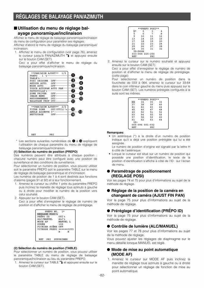
RÉGLAGES DE BALAYAGE PAN/AZIMUTH
■ Utilisation du menu de réglage bal-ayage panoramique/inclinaison
Affichez le menu de réglage de balayage panoramique/inclinaisondu menu de configuration pour paramétrer ses réglages. Affichez d’abord le menu de réglage du balayage panoramique/inclinaison.1. Affichez le menu de configuration (voir page 76), amenez
le curseur jusqu’à PAN/AZIMUTH O et appuyez ensuitesur le bouton CAM (SET). Ceci a pour effet d’afficher le menu de réglage dubalayage panoramique/inclinaison.
* Les sections suivantes numérotées de q à !4 expliquentl’utilisation de chaque paramètre du menu de réglage debalayage panoramique/inclinaison.
(1) Sélection du numéro de position (PREPO)Des numéros peuvent être attribués à chaque position :chacune numéro peut être configuré avec une position desurveillance et des conditions de surveillance. Pour sélectionner un numéro de position, vous pouvez utilisersoit le paramètre PREPO soit le paramètre TABLE sur le menude réglage de balayage panoramique et d'inclinaison. Les numéros de position de 1 à 4 sont destinés aux fonctionsd’alarme (pages 91 et 92) et à leur fonctionnement. 1. Amenez le curseur au chiffre 1 près du paramètre PREPO
puis inclinez la manette de réglage tous azimuts à gaucheou à droite pour modifier le numéro de la position verscelui souhaité.
2. Appuyez sur le bouton CAM (SET). Ceci a pour effet d’enregistrer le réglage de numéro deposition et d’afficher le menu de réglage de préréglage.
(2) Sélection du numéro de position (TABLE)Pour sélectionner un numéro de position, vous pouvez utiliserle paramètre TABLE du menu de réglage de balayagepanoramique/inclinaison au lieu du paramètre PREPO. 1. Amenez le curseur sur TABLE O et appuyez ensuite sur le
bouton CAM (SET).
2. Amenez le curseur sur le numéro souhaité et appuyezensuite sur le bouton CAM (SET). Ceci a pour effet d’enregistrer le réglage de numéro deposition et d’afficher le menu de réglage de préréglage.(cette page) Pour sélectionner un numéro de position dans lafourchette de 033 à 064, amenez le curseur sur 33-64dans le coin inférieur gauche du menu puis appuyez sur lebouton CAM (SET). Les numéros préréglés configurés à lasuite sont les mêmes.
Remarques:• Un astérisque (*) à la droite d’un numéro de position
indique qu’il a déjà une position préréglée qui lui a étéassignée. Le numéro de position d’origine est signalé par la lettre Hà côté de l’astérisque.
• Lorque le curseur est situé sur un numéro de position quipossède une position d’identification, le texte de laposition d’identification s’affiche à côté de l’ID : sur l’écrande menu.
● Paramétrage de positionnement(REGLAGE POSI)
Voir les pages 74 et 75 pour plus d’informations au sujet de laméthode de réglage.
● Réglage de la position de la caméra enchangeant de caméra (AJUST FIN PAN)
Voir la page 75 pour plus d’informations au sujet de laméthode de réglage.
● Préréglage d’identification (PRÉPO ID)Voir la page 75 pour plus d’informations au sujet de laméthode de réglage.
● Contrôle de lumière (ALC/MANUEL)Voir les pages 77 et 78 pour plus d’informations au sujetde la méthode de réglage.Vous pouvez ajuster les réglages de diaphragme sur lemenu détaillé lorsque MANUEL est réglé.
● Mode de mise au point automatique(MODE AF)
1. Amenez le curseur sur MODE AF puis inclinez lamanette de réglage tous azimuts à gauche ou à droitepour sélectionner un réglage de fonction de mise aupoint automatique.
-82-
**PAN/AZIM AJUST** 1/2PREPO 1 ∫TABLE∫POSI ORIGINE OFFRETOUR AUTO OFFMODE AUTO OFFTOUCH AUTOPAN AUTO PANPATROUILLE∫ZONE PRIVEE OFFIMAGE MEMO OFFRETOURNEMENT OUIBALAYAGE PROP OUI
**PAN/AZIM AJUST** 2/2TITRE ZONE OUI(UTIL)∫ANGLE AZIMUTH 0°NETTOYAGE OFF
RET PRI
q
e
t
u
o
!1
w
r
y
i
!0
!2!3
!4
**PREPO POSI** 1* 2 3 4 5 6 7 8 9 10 11 12 13 14 15 16 17 18 19 20 21 22 23 24 25 26 27 28 29 30 31 32 ID:DOOR 033-064 225-256 RET PRI
**PREPO POSI** 33 34 35 36 37 38 39 40 41 42 43 44 45 46 47 48 49 50 51 52 53 54 55 56 57 58 59 60 61 62 63 64 ID: 065-096 001-032 RET PRI
PREPO NO. 1*REGLAGE POSI∫PRÉPO ID OUI∫ALC/MANUEL ALC∫MODE AF MANUEL LDURÉE 10SFICHIER SCÉNE OFFVITESSE PREPO ••••••I255 B H
RET PRI SUPPRIMER
WV-CS954_FR 09.1.21 2:55 PM ページ82

-83-
MANUEL S.M.L : La mise au point automatique nefonctionne pas après le déplacementvers une position préréglée.
AUTO S.M.L : La mise au point automatiquefonctionne après le déplacementvers une position préréglée.
● Temps d’arrêt de séquence/tri (DURÉE)Cette section explique comment régler la durée pendantlaquelle la caméra s’arrête (durée pendant laquelle elles’arrête de tourner), pendant laquelle elle enregistre lascène lorsque les différentes positions préréglées de laséquence sont activées et pendant laquelle les opérationssont classées (page 84). 1. Amenez le curseur sur DURÉE puis inclinez la manette
de réglage tous azimuts à gauche ou à droite poursélectionner un réglage de durée d’arrêt. L’inclinaison de la manette de réglage tous azimuts faitdérouler l’affichage de durée d’arrêt dans l’ordreindiqué ci-dessous. (unité : sec, min)
● Réglage de fichier de scène (FICHIER SCÉNE)10 fichiers de scène au maximum, chacun contenant desparamétres de caméra pour un emplacement spécifique(scène), peuvent être mis en mémoire. Les fichiers descène sont gérés en utilisant des numéros de fichier descène de 1 à 10, et ils peuvent être sélectionnés au coursde la configuration des réglages de position préréglée. Les procédures suivantes montrent comment sélectionnerun fichier de scène et comment configurer les réglages defichiers de scène.
(1) Sélection d’un fichier de scène Utilisez cette procédure lorsque vous souhaitez appliquer lesparamètres d’un fichier de scène précédemment sauvegardépendant la configuration d’une position préréglée. 1. Amenez le curseur sur FICHIER SCÉNE puis inclinez-le
à gauche ou à droite pour sélectionner le numéro defichier de scène souhaité.
(2) Configurer les paramètres de fichier de scène1. Amenez le curseur sur FICHIER SCÉNE puis inclinez-le
à gauche ou à droite pour sélectionner le numéro defichier de scène à configurer.
2. Appuyez sur le bouton CAM (SET). Ceci permet d’afficher le menu de configuration dufichier de scène.Les paramètres suivants peuvent être réglés avec lemenu de réglage de fichier de scène. Voir les réglagesde caméra pour des détails sur chaque réglage.
• SHUTTER (page 78)• CAG (page 78)• VISION NUIT (page 78) • BAL BLC (page 79, 80)• DÉTECT MVT (page 90)
● Paramétrage de la vitesse préréglée(VITESSE PREPO)
Règle la vitesse à laquelle la caméra active les différentespositions préréglées de la séquence et classe lesopérations (page 84). 1. Amenez le curseur sur VITESSE PREPO puis inclinez la
manette de réglage tous azimuts à gauche ou à droitepour changer le réglage de vitesse. Lorsque le réglageest effectué vers B, la vitesse diminue et vers H, elleaugmente.
● Suppression de positions préréglées(SUPPRIMER)
1. Amenez le curseur sur SUPPRIMER et appuyez ensuitesur le bouton CAM (SET). Cela a pour effet de supprimer le contenu du numérode position en cours de sélection et d’afficher le menude sélection de position.
2S ↔ 3S ↔ 5S ↔ 10S ↔ 30S ↔ 1MIN
4MIN ↔ 3MIN ↔ 2MIN
PREPO NO. 1*REGLAGE POSI∫PRÉPO ID OUI∫ALC/MANUEL ALC∫MODE AF MANUEL LDURÉE 10SFICHIER SCÉNE OFFVITESSE PREPO ••••••I255 B H
RET PRI SUPPRIMER
PREPO NO. 1*REGLAGE POSI∫PRÉPO ID OUI∫ALC/MANUEL ALC∫MODE AF MANUEL LDURÉE 10SFICHIER SCÉNE 1∫VITESSE PREPO ••••••I255 B H
RET PRI SUPPRIMER
**FICHIER SCÉNE 1**SHUTTER OFFCAG OUI(MOYEN)VISION NUIT OFFBAL BLC BAL BLC PERM1∫DÉTECT MVT OFF
RET PRI
PREPO NO. 1*REGLAGE POSI∫PRÉPO ID OUI∫ALC/MANUEL ALC∫MODE AF MANUEL LDURÉE 10SFICHIER SCÉNE OFFVITESSE PREPO ••••••I255 B H
RET PRI SUPPRIMER
**PREPO POSI** 1 2* 3* 4* 5* 6* 7* 8* 9* 10* 11* 12* 13* 14* 15* 16* 17* 18* 19* 20* 21* 22* 23* 24* 25* 26* 27* 28* 29* 30* 31* 32* ID:DOOR 033-064 225-256 RET PRI
PREPO NO. 1*REGLAGE POSI∫PRÉPO ID OUI∫ALC/MANUEL ALC∫MODE AF MANUEL LDURÉE 10SFICHIER SCÉNE OFFVITESSE PREPO ••••••I255 B H
RET PRI SUPPRIMER
WV-CS954_FR 09.1.21 2:55 PM ページ83

-84-
Remarques:• Le réglage ORIG devrait être sélectionné lorsque
vous souhaitez laisser la caméra en positiond’origine et effectuer occasionnellement unbalayage panoramique et une inclinaison ou sivous souhaitez activer SÉQ.
• PTR1-4 affiche uniquement le nombre de routinesde patrouille configurées (page 86).
(5) Réglage du mode automatique (MODE AUTO) Utilisez ce mode de réglage pour paramétrer le mode demouvement de la caméra (OFF, SÉQ, TRI, AUTO PAN,PATR1-4, SUIVI AUTO). Après avoir sélectionné AUTO PAN, vous pouvez utiliser lemenu de réglage AUTO PAN pour configurer les réglagesde détail. 1. Amenez le curseur sur MODE AUTO puis inclinez la
manette de réglage tous azimuts à gauche ou à droitepour sélectionner un réglage de mode de mouvementde caméra.OFF :Mouvement manuel uniquementSÉQ :Commute séquentiellement entre les
positions préréglées selon le numéro deséquence. (mouvement séquentiel)
TRI :Commute séquentiellement entre lespositions préréglées dans le sens con-traire des aiguilles d’une montre, à partirde la position d’origine de la caméra.(mouvement tri)
AUTO PAN :La caméra balaye automatiquement lerayon spécifié par PAN. SélectionnerAUTO PAN et appuyer sur le boutonCAM (SET), fait apparaître le menu desréglages AUTO PAN qui peut être utilisépour configurer des réglages détaillés.(page 85)
PATR 1 à 4 :Fait fonctionner la caméra selon lesparamètres de la fonction patrouille.
SUIVI AUTO :Le pistage automatique a lieu pour lesobjets en déplacement dans les condi-tions suivantes. L’objet en déplacement doit être plusgrand que l’un des blocs de l’écran(1/48ème de la zone de l’écran) et doitprésenter un contraste comparatif de 5% par rapport à l’image d’arrière-plan
Remarques :• Le pistage automatique couvre un rayon horizontal
jusqu’à directement sous la caméra. La fonction deretournement numérique (page 88) ne fonctionnepas. De même le rayon de balayage panoramiquepeut être limité par l’utilisation du réglage LIMITPAN (page 85).
• La fonction automatique de pistage intégré à ce système,piste facilement des objets en mouvement sur l’écran.Les sujets en mouvement ne sont pas automatiquementpistés au cours des situations suivantes.• Si de multiples sujets en mouvement sont à l’écran.• Si les sujets bougent trop rapidement• Si le sujet présente peu de contraste• Si les sujets sont mouvement sont trop grands ou
trop petits• Si l’image est sombre• Si l’image scintille
(3) Réglage de position d’origine (POSI ORIGINE)Une position préréglée en cours peut être désignée entant que position d’origine. En appuyant sur le bouton HOME du contrôleur desystème, la caméra passe sur la position attribuée à laposition d'origine. Utilisez la procédure suivante pourattributer à une position préréglée la position d’origine. 1. Amenez le curseur sur POSI ORIGINE puis inclinez la
manette de réglage tous azimuts à gauche ou à droitepour sélectionner le numéro de position de la positionpréréglée qui sera la position d’origine. La position préréglée choisie devient la positiond’origine. Si vous ne souhaitez pas utiliser cettefonction, sélectionnez OFF pour le réglage POSIORIGINE.
(4) Réglage de retour automatique (RETOUR AUTO)Ce réglage peut être utilisé pour affecter le retourautomatique à un mode particulier si un certain tempss’écoule sans qu’aucune opération ne soit effectuée. 1. Amenez le curseur sur RETOUR AUTO puis inclinez la
manette de réglage tous azimuts à gauche ou à droitepour sélectionner un réglage de déclenchement deretour automatique. L’inclinaison de la manette de réglage tous azimuts faitdérouler l’affichage de retour automatique dans l’ordreindiqué ci-dessous. (unité : sec, min)
2. Si vous aviez sélectionné à l’étape 1 un réglage autreque OFF, appuyez sur le bouton CAM (SET) puisinclinez la manette de réglage sur la gauche ou sur ladroite pour sélectionner un mode de retourautomatique.
OFF : En mode automatique, fait sortir de cemode lorsque le temps de déclenchementest écoulé.
AUTO (MODE AUTO réglage non sur OFF): Revientau mode automatique lorsque le temps dedéclenchement est écoulé.
AUTO (MODE AUTO réglage OFF): Revient à la posi-t ion d’origine lorsque le temps dedéclenchement est écoulé.
ORIG : Revient à la position d’origine lorsque letemps de déclenchement est écoulé.
APAN : Active le balayage panoramique automa-tique lorsque le temps de déclenchementest écoulé.
SÉQ : Active la fonction de séquence lorsque letemps de déclenchement est écoulé.
TRI : Active la fonction de tri lorsque le tempsde déclenchement est écoulé.
PTR 1 à 4 : Active la fonction de patrouille lorsque letemps de déclenchement est écoulé.
SUIV : Après écoulement du temps de déclenche-ment, la caméra retourne à sa position d'o-rigine et le pistage automatique com-mence. Après cela et après un délai pen-dant lequel le mouvement s’est arrêté, lacaméra retourne à sa position d’origine etse remet à continuer le pistage automa-tique.
30MIN ↔ 20MIN ↔ 10MIN ↔ 5MIN ↔ 3MIN ↔ 2MIN ↔ 1MIN
OFF ↔ 1S ↔ 2S ↔ 3S ↔ ....... ↔ 10S ↔ 20S ↔ 30S ↔ 40S
60MIN 50S
↔↔
↔↔
OFF ↔ AUTO ↔ ORIG ↔ APAN ↔ SÉQ ↔ TRI
SUIV ↔ PTR4 ↔ PTR3 ↔ PTR2 ↔ PTR1
WV-CS954_FR 09.1.21 2:55 PM ページ84

4. Amenez le curseur sur DURÉE puis inclinez la manettede réglage tous azimuts à gauche ou à droite poursélectionner un réglage de point de départ et de duréede temporisation au point de fin de course. L’inclinaison de la manette de réglage tous azimuts faitdérouler l’affichage de durée d’arrêt dans l’ordreindiqué ci-dessous. (unité : sec)
5. Amenez le curseur sur LIMIT PAN puis inclinez lamanette de réglage tous azimuts à gauche ou à droitepour activer ou désactiver la fonction. OUI :Limite le balayage manuel à la zone entre le
point de depart et le point de fin de course. Lerayon AZIMUTH va de l’horizontale à droit vers lebas. Quand ce réglage est utilisé, sélectionnezOFF pour le réglage de SANS FIN (étape 3).
OFF :Permet le balayage panoramique manuel horsde la zone entre le point de depart et le point defin de course.
LIMIT PAN LIMIT PAN permet le balayage panoramique de la zonecomprise entre le point de départ et le point de fin decourse spécifié à l’étape 1, mais pas de la zone entre lepoint de fin de course et le point de départ.
Remarques:• Lorsque le balayage panoramique, l’inclinaison, le
changement de focale ou la mise au point en modeSÉQ, TRI ou PATR sont contrôlés manuellement, lafonction de mode automatique doit être débrayée.Pour activer le mode automatique, sélectionnez ànouveau le mode auto souhaité ou définissez unedurée pour RETOUR AUTO (retour auto) dans lemenu AJUST.
• Quand 0S est sélectionné, la caméra s’arrête sanstemporisation et commence.
• Le mode de rafraîchissement automatique peutêtre activé pendant la lecture de patrouille ou lemode automatique pour étalonner la position del’objectif.
(6) Paramétrage de touche de balayage panoramiqueautomatique (TOUCH AUTOPAN)
Règle les opérations de la caméra lorsque la fonctionAUTO PAN est activée à partir du contrôleur du système(page 84).1. Amenez le curseur sur TOUCH AUTOPAN puis inclinez
la manette de réglage tous azimuts à gauche ou àdroite pour sélectionner un réglage de mode demouvement de caméra. L’inclinaison de la manette de réglage tous azimuts faitdérouler les réglages dans l’ordre indiqué ci-dessous.
Remarques:• Le mode automatique peut être déclenché mais
pas arrêté avec la touche AUTO PAN. • PATR1-4 affiche uniquement le nombre de routines
de patrouille configurées (page 86).
L’inclinaison de la manette de réglage tous azimuts faitdérouler les réglages dans l’ordre indiqué ci-dessous.
Remarques :• Le mode automatique est automatiqement quitté
lorsqu’un PAN/AZIMUTH ou un ZOOM/FOCUS manuelest effectué alors qu’AUTO PAN fonctionne et quePAN/AZIMUTH effectue des mouvements SÉQ, TRI,PATR, ou SUIVI AUTO. Notez cependant que le contenudu menu de réglage ne change pas. Pour retourner enmode automatique, ouvrez le menu de configuration etfermez-le à nouveau. Le mode automatique seraégalement activé lorsque le temps de déclenchement deretour automatique est écoulé (page 84).
• Pendant le fonctionnement, il se peut que l’objectifpasse en mode de rafaîchissement.
• PATR1-4 affiche uniquement le nombre de routinesde patrouille configurées (page 86).
● Configuration des réglages détaillésd’AUTO PAN
1. Exécutez les étapes suivantes pour régler les points dedépart et de fin de course de PAN. (1) Amenez le curseur sur POSITION, appuyez sur le
bouton CAM (SET) puis amenez le curseur surDEMARAGE.
(2) Servez-vous de la manette de réglage tous azimutspour amenez le curseur sur le point de départ PANsouhaité et appuyez ensuite sur le bouton CAM(SET). Ceci a pour effet de définir le point de départ et dedéplacer le curseur sur FIN.
(3) Servez-vous de la manette de réglage tous azimutspour amener le curseur au point de fin de course PANsouhaité et appuyez ensuite sur le bouton CAM (SET).Cela a pour effet de définir le point de départ et dedéplacer le curseur sur POSITION.
2. Amenez le curseur sur VITESSE puis inclinez la manette deréglage tous azimuts à gauche ou à droite pour sélectionnerun réglage de vitesse de balayage panoramique. Lorsque le réglage est effectué vers “H“ (à droite), lavitesse augmente et vers “L“ (à gauche), elle diminue.
3. Amenez le curseur sur SANS FIN puis inclinez la manettede réglage tous azimuts à gauche ou à droite pouractiver ou désactiver le balayage panoramique infini. OUI :Balaye du point de départ au point de fin de
course puis continue de balayer dans la mêmedirection du point de fin de course au point dedépart. Sélectionnez OFF pour le réglage deLIMIT PAN (étape 5) pour utiliser ce réglage. Lebalayage sera recommencé en permanence.
OFF :Balaye du point de départ au point de fin decourse puis inverse la direction pour balayer dupoint de fin de course au point de départ. Le bal-ayage est répété en permanence.
-85-
OFF ↔ SÉQ ↔ TRI ↔ AUTO PAN ↔ PATR1 ↔ PATR2
SUIVI AUTO ↔ PATR4 ↔ PATR3
**AUTO PAN**
POSITION DEMARAGE FINVITESSE •••I•••127 B HSANS FIN OFFDURÉE 1SLIMIT PAN OFF
RET PRI
0S ↔ 1S ↔ 2S ↔ 3S ↔ 5S ↔ 10S ↔ 20S ↔ 30S
AUTO PAN ↔ SÉQ ↔ TRI ↔ PATR1 ↔ PATR2
SUIVI AUTO ↔ PATR4 ↔ PATR3
Point de départ
Point de fin de course
Zone AUTO PAN
Zone de LIMIT PAN
Caméravidéo
WV-CS954_FR 09.1.21 2:55 PM ページ85

-86-
(2) Faites fonctionner la caméra pour mettre les mouvementsen mémoire. “MÉMORISATION (***S)” s’affiche au milieu de l’écran lorsqueles mouvements sont en cours d'enregistrement. (unité : sec)* “(***S)” indique le temps qui reste pour la mémorisation.
(3) Le menu de configuration s’affiche et la mémorisations’arrête. La mémorisation des mouvements s’arrête quand ledélai atteint “0S“. (unité : sec)
Remarques : • Sélectionner MÉMORISATION pour apprendre à la
caméra une routine de patrouille, fait que lesparamètres suivants sont mis en mémoire en mêmetemps que les mouvements de la caméra.(1) Paramètres en début de routine
• Positions PAN, AZIMUTH, ZOOM, et FOCUS • Niveau IRIS • Vitesse d’obturation (SHUTTER)• Réglage de gain (CAG) • Réglage de l’accroissement de la sensibilité
électronique (VISION NUIT) • Réglage de la blance des blancs (BAL BLC) • IMAGE MEMO• TITRE ZONE• ZONE PRIVEE• CAMÉRA ID• LIMIT PAN• LIMITE ZOOM• ANGLE AZIMUTH• BURST• NETTOYAGE
(2) Pendant les movement de la caméra• Positions PAN, AZIMUTH, ZOOM, et FOCUS • Fonctionnement d’IRIS • Positionnement préréglé
• Le mode mise au point automatique ne fonctionne paspendant les opérations de patrouille. Du fait dumécanisme du zoom, l’image est floue quand lacaméra fait un zoom avant en grand angle (WIDE). Leflou de l’image peut être réduit en commençant autéléobjectif (TELE) lors de l’enregistrement d’uneopération de zoom.
• En mode de lecture de patrouille, le mouvement dela caméra peut parfois dévier de la routine saisielorsque la routine comporte un mouvement versune position préréglée. Si cela se produit, saisissezà nouveau la routine d’opérations manuelles pour lamémorisation de patrouille.
• En mode de lecture de patrouille, le passageautomatique au noir et blanc ne fonctionne pas.
• En mode de lecture de patrouille, lorsquel’alimentation du contrôleur de système est misesous ou hors tension, la lecture de patrouilles’interrompt. Dans ce cas, appuyez à nouveau surla touch PATROUILLE LECTURE. (Si RETOURAUTO est réglé sur OUI, la lecture de patrouillereprendra après écoulement du délai de retour).
• La fonction patrouille couvre un rayon horizontaljusqu’à directement sous la caméra. La fonction deretournement numérique (page 88) ne fonctionne pas.
(8) Réglage de zone de confidentialité (ZONE PRIVEE)La fonction Zone de confidentialité permet de masquerdes zones spécifiques de la scène (écran) de manièrequ’elles n’apparaissent pas. 8 zones de confidentialité, aumaximum, peuvent être configurées.
(7) Réglage de la fonction de patrouille (PATROUILLE)La fonction patrouille garde en mémoire les opérationsmanuelles pour pouvoir les relire en cas de nécessité. 1. Dirigez la caméra, menu fermé, sur le point de départ
de la routine dont vous souhaitez vous rappeler.2. Amenez le curseur sur NUMERO puis inclinez-le à
gauche ou à droite pour sélectionner le numéro deroutines de patrouille.L’inclinaison de la manette de réglage tous azimuts faitdérouler les réglages dans l’ordre indiqué ci-dessous.Le temps de sauvegarde disponible dépend dunombre de routines. L’affichage du temps de stockagechange selon l’ordre ci-dessous. (unité : sec, min)
Notez que le temps de patrouille total est de deuxminutes et que le temps affecté à chaque routinedépend du nombre de routines de patrouillesconfiguré. Les valeurs entre parenthèses indiquent letemps de chaque routine de patrouille (2 minutes pourune patrouille, 1 minute pour deux, et 30 pour quatre)
Si vous désirez modifier le nombre des routines depatrouille, effacez d’abord toutes les routines depatrouilles actuellement mémorisées. Pour tout effacer,amenez le curseur sur RESET et appuyez sur le boutonCAM (SET).
3. Amenez le curseur sur un numéro de PATR (PATR 1 à4) puis inclinez la manette de réglage à gauche ou àdroite pour sélectionner un réglage de patrouille. --- : Désactive la routine de patrouil le
sélectionnée.LECTURE : Exécute la routine de patrouil le
sélectionnée. (cette page)MÉMORISATION: Sélectionnez cette option pour
apprendre à la caméra une série de mouve-ments (routine de patrouille). (Un astérisque(*) à la droite d’un numéro de PATR indiquequ’il a déjà une routine de patrouille qui lui aété assignée). (cette page)
SUPP → APP SET: Appuyez sur le bouton CAM (SET)pour effacer une routine de patrouille existante.
<Si LECTURE est sélectionnée>(1) Appuyez sur la touche F2 du contrôleur du système
pour fermer le menu. L’orientation de la caméra passe à la positionenregistrée de départ puis la caméra commence à lirele mouvement mis en mémoire.
(2) Lorsque la lecture est terminée, exécutez manuellement unbalayage, une inclinaison, un zoom et une mise au point.
<Si MÉMORISATION est sélectionnée>(1) Appuyez sur la touche F2 du contrôleur du système
pour fermer le menu. La position de départ est mémorisée et les mouvementsde la caméra peuvent être mis en mémoire.
1(2MIN) ↔ 2(1MIN) ↔ 4(30S)
**PATROUILLE**
NUMERO 4(30S) PATR1* LECTURE PATR2 --- PATR3 --- PATR4 ---
RESET RET PRI
WV-CS954_FR 09.1.21 2:55 PM ページ86

6. Servez-vous de la manette de réglage tous azimutspour pointer la caméra sur l’emplacement à masqueret appuyez ensuite sur le bouton CAM (SET). Ceci a pour effet d’enregistrer la position de la caméraet de revenir au menu de réglage de zone.
7. Amenez le curseur sur → BOUTON SET à droite deZOOM/FOCUS, et appuyez ensuite sur le bouton CAM(SET). Le menu de réglage ZOOM/FOCUS s’affiche.
8. Déplacez la manette de réglage à gauche, à droite, enhaut et en bas pour ajuster la position de la mise aupoint et appuyez ensuite sur le bouton CAM (SET). Ceci a pour effet de terminer la procédure d’ajustementet de retourner au menu de réglage de zone. Le zoom peut être réglé pour un grossissement de 1 à 10.
9. Amenez le curseur sur AIRE puis inclinez la manettede réglage tous azimuts à gauche ou à droite pourchanger le format du cadre de zone. Faire passer le réglage vers le côté – réduit la taille ducadre de zone, alors que vers le côté + il l’agrandit.Notez que le rapport d’aspect du cadre de zone esttoujours de 3:4. De même, le format du cadre de zonepeut être modifié en fonction du pourcentage de zoom.
10. Amenez le curseur sur REGLAGE et appuyez ensuitesur le bouton CAM (SET). Cela termine la procédure de réglage de zone deconfidentialité ; le menu de sélection de numéro dezone s’affiche. Si vous sélectionnez SUP au lieu de REGLAGE, lesréglages de zone sont effacés et vous revenez aumenu de sélection de numéro de zone.
(9) Maintien d’Image (IMAGE MEMO)Cette fonction fige l’image en cours jusqu’à ce que lacaméra ait atteint sa position préréglée. Cette fonction estbien utile lors de l’utilisation d’un appareil d’interface enréseau pour surveiller les images d’une caméra sur unréseau. 1. Amenez le curseur sur IMAGE MEMO puis inclinez la
manette de réglage tous azimuts à gauche ou à droitepour basculer entre activer ou désactiver la fonction. OUI : Maintient la dernière image juqu’à ce que la
caméra atteigne sa position préréglée. Cependant, l’image fixe risque d’être déforméedu fait du balayage panoramique ou de l’inclinai-son.
OFF: L’image observée par la caméra continue d’êtreaffichée pendant que la caméra opère sondéplacement jusqu’à sa position préréglée.
Remarques :• Certaines orientations de la caméra peuvent rendre
visibles des zones de confidentialité masquées.• La fonction de zone de confidentialité ne masque pas
les zones pendant la routine d’initialisation effectuéejuste après la mise sous tension de la caméra.
• La position de zone peut varier si les paramètres dustabilisateur sont modifiés après réglage de la zone deconfidentialité.
1. Amenez le curseur sur ZONE PRIVEE puis inclinez lamanette de réglage tous azimuts à gauche ou à droitepour sélectionner un réglage de zone deconfidentialité. OUI (1) :Active la fonction de zone de confidentialité. OUI (2) :Active la fonction de zone de confidentialité.
(Mosaïque) OFF :Désactive la fonction de zone de confidentialité.Exécutez les étapes suivantes pour configurer leszones de confidentialité.
2. Amenez le curseur sur ZONE PRIVEE et appuyezensuite sur le bouton CAM (SET). Le menu de sélection de numéro de zone (NUMEROZONE) s'affiche. L’image s’affiche en plein écran grandangle total (WIDE) si aucune zone de confidentialitén’est définie pour le numéro de zone en cours.
3. Amenez le curseur sur NUMERO ZONE puis inclinez lamanette de réglage tous azimuts à gauche ou à droitepour sélectionner le numéro de zone (1à 8) que voussouhaitez configurer. Un astérisque (*) sur la droite d’un numéro indique qu’ila déjà une zone de confidentialité qui lui a été attribuée.La sélection d’un tel numéro de zone, agrandit l’imageselon le réglage de zoom qui était défini lorsque sesréglages de zone de confidentialité ont été configurés.
4. Appuyez sur le bouton CAM (SET). Le menu de configuration de zone s’affiche. L’apparence dumenu dépend des réglages de zone.
Le cadre de zone actuellement configuré apparaît au centrede l'image. Si vous exécutez les étapes qui restent à effectuerdans cette procédure, vous effacerez le cadre de zone encours et le remplacerez par le nouveau que vous configurez.
5. Amenez le curseur sur → BOUTON SET à droite dePAN/AZIMUTH, et appuyez ensuite sur le bouton CAM(SET). Ceci a pour effet d'afficher le menu de réglagePAN/AZIMUTH.
-87-
**NUMERO ZONE 1 /8**
RET PRI
**NUMERO ZONE 3 /8**PAN/AZIMUTH ∑BOUTON SETZOOM/FOCUS ∑BOUTON SET
AIRE •••I•••128 REGLAGE SUP - + RET PRI
Cadre de zone
**NUMERO ZONE 3 /8**PAN/AZIMUTH ∑BOUTON SETZOOM/FOCUS ∑BOUTON SET
H AZIMUTH B/G PAN D
AIRE •••I•••128 REGLAGE SUP - + RET PRI
**NUMERO ZONE 3 /8**PAN/AZIMUTH ∑BOUTON SETZOOM/FOCUS ∑BOUTON SET H ZOOM B/G FOCUS D
AIRE •••I•••128 REGLAGE SUP - + RET PRI
WV-CS954_FR 09.1.21 2:55 PM ページ87

-88-
être utilisé pour configurer des réglagesdétaillés. (cette page)
OUI (UTIL): Affiche le texte saisi par l’utilisateur. Le fait de sélectionner OUI (UTIL) et d’appuyersur le bouton CAM (SET), fait apparaître lemenu de sélection du titre de zone (UTIL) quipeut être utilisé pour configurer des réglagesdétaillés. (page 89)
OFF : Désactive l’affichage des indicateurs d’orienta-tion de zone de titre ainsi que le texte.
(1) Si OUI (NESO) est sélectionné Après avoir sélectionné OUI (NESO), vous pouvez utiliserle menu de réglage de position (NESO) pour configurerles réglages de détail. Une fois que vous définissez la direction du nord (N) lesautres orientations s’affichent automatiquement. 1. Amenez le curseur sur → BOUTON SET à droite de
PAN/AZIMUTH, et appuyez ensuite sur le bouton CAM(SET). Ceci a pour effet d'afficher le menu de réglagePAN/AZIMUTH.
2. Pointez la caméra vers le nord à l’aide de la manettede réglage tous azimuts et appuyez ensuite sur lebouton CAM (SET).
3. Amenez le curseur sur → BOUTON SET à droite deZOOM/FOCUS, et appuyez ensuite sur le bouton CAM(SET). Le menu de réglage ZOOM/FOCUS s’affiche.
4. Déplacez la manette de réglage à gauche, à droite, enhaut et en bas pour ajuster la position de la mise aupoint et appuyez ensuite sur le bouton CAM (SET).
5. Amenez le curseur sur POSITION O et appuyezensuite sur le bouton CAM (SET). Ceci a pour effet d’afficher le menu de réglage de laposition d’affichage de l’ID.
6. Utilisez la manette pour sélectionner une positiond’affichage de titre de zone et appuyez ensuite sur latouche MON (ESC).
(10) Réglage de retournement numérique (RETOURNEMENT) Une caméra doit normalement s’arrêter pour pointer versle bas pendant l’inclinaison. Mais avec le retournementnumérique, la caméra peut s’incliner de 0° à 180 ° d’unseul mouvement. Il devient ainsi possible de suivre sansproblème des sujets passant directement sous la caméraL’image est retournée verticalement et horizontalementquand la caméra est à un angle d'environ 135°. 1. Amenez le curseur sur RETOURNEMENT puis inclinez la
manette de réglage tous azimuts à gauche ou à droitepour basculer entre activer ou dé sactiver la fonction. OUI : Active le retournement numérique. Notez que le
rayon de retournement est de 0° à 90° lorsqueOUI est sélectionné sur le réglage LIMIT PAN.
OFF: Désactive le retournement numérique. Avec ceréglage le rayon de retournement est de 0° à 90°.
Remarques :• Le retournement numérique est effectué uniquement
lorsque la manette de réglage est tenue directementvers le bas. Elle ne se fait pas si la manette deréglage est penchée sur une autre direction.
• Lorsque OFF est sélectionné pour RETOURNEMENT,les étapes suivantes doivent être effectuées pourpencher la caméra à 180°.(1)Basculez la manette de réglage vers le bas pour
que la caméra pointe aussi droit vers le bas. (2)Inclinez la manette de réglage vers la gauche ou
la droite pour un balayage de la caméra à 180°. (3)Inclinez la manette de réglage vers le haut.
• Désactivez momentanément RETOURNEMENT etréglez la limite zoom sur un grossissement de 30xou moins avant de régler une position préréglée àpartir du contrôleur système WV-CU360C.Notez que le retournement numérique ne peut êtredéfini pour un rayon de retournement de 90° à 180°.
(11) Réglage de vitesse du balayage panoramique etd’inclinaison proportionnelle (BALAYAGE PROPO)
Cette fonction optimise l’image en ajustant automatiquementla vitesse PAN/AZIMUTH (rotation verticale/horizontale) enfonction du rapport zoom.1. Amenez le curseur sur BALAYAGE PROP, puis inclinez
la manette de réglage tous azimuts à gauche ou àdroite pour basculer entre activer ou désactiver lafonction. OUI : La vitesse de balayage panoramique et d’incli-
naison est inversement proportionnelle au rap-port zoom.
OFF: La vitesse est constante au niveau le plus rapidequel que soit le rapport zoom.
(12) Réglage du titre de zone (TITRE ZONE) Cette fonction vous permet d’afficher un indicateur dedirection qui apparaît à l’image pour indiquer l’orientationde l’emplacement qui est montré sur l’écran. Du texte peut aussi, si l’on veut, s’afficher à la place desindicateurs d’orientation. Les indicateurs d’orientation sontN (nord) NE (nord est), E (est), SE (sud est), S (sud), SW(sud ouest), W (ouest) et NW (nord ouest).1. Amenez le curseur sur TITRE ZONE puis inclinez la
manette de réglage tous azimuts à gauche ou à droitepour activer ou désactiver la fonction. OUI (NESO): Affiche les indicateurs d’orientation.
Le fait de sélectionner OUI (NESO) et d’appuy-er sur le bouton CAM (SET), fait apparaître lemenu de réglage de position (NESO) qui peut
**DIRECTION(NESO)**PAN/AZIMUTH ∑BOUTON SETZOOM/FOCUS ∑BOUTON SETPOSITION∫
+ N
RET PRI
**DIRECTION(NESO)**PAN/AZIMUTH ∑BOUTON SETZOOM/FOCUS ∑BOUTON SETPOSITION∫ H AZIMUTH B/G PAN D + N
RET PRI
**DIRECTION(NESO)**PAN/AZIMUTH ∑BOUTON SETZOOM/FOCUS ∑BOUTON SETPOSITION∫ H ZOOM B/G FOCUS D + N
RET PRI
WV-CS954_FR 09.1.21 2:55 PM ページ88

Voir les étapes 3 à 5 de “Réglages de l’identifiant de lacaméra vidéo” page 73 pour des détails sur la saisiede texte pour le titre de zone et pour indiquer saposition sur l’écran.
5. Si vous le souhaitez, répétez les étapes 1 à 4 pour lesautres numéros de zone.
(13) Réglage de l’angle d’inclinaison (ANGLE AZIMUTH) Le fait de sélectionner 5° pour le réglage de ANGLEAZIMUTH permet une inclinaison dans une fourchette quiva de -5° à 185°. 1. Amenez le curseur sur ANGLE AZIMUTH puis inclinez
la manette de réglage tous azimuts à gauche ou àdroite pour basculer le réglage entre 0° et 5°.
Remarques :• Le fait de zoomer jusqu’à WIDE alors que 5° est
sélectionné pour l’angle d’inclinaison, fait que lamoitié supérieure de l’image est cachée.
• Avec certains sujets, l’effet CAG (contrôle de gain)fait que l’image peut devenir blanche.
(14) Réglages de nettoyage (NETTOYAGE) Cette caméra vidéo utilise une “bague collectrice” pour latransmission de l'alimentation électrique et des signaux.Une bague collectrice encrassée peut provoquer unedétérioration de la qualité de l’image ainsi que du bruit. La fonction de nettoyage effectue un nettoyage environune fois par semaine pour garder la bague collectricepropre. 1. Amenez le curseur sur NETTOYAGE puis inclinez la
manette de réglage tous azimuts à gauche ou à droitepour l’activer ou la désactiver. Le mot NETTOYAGE s’affiche au mileu de l’écran alorsque le processus de nettoyage est en cours.
Remarque: Sélectionnez OFF pour NETTOYAGE lorsquele contrôleur de système télécharge des donnéespréréglées de ou vers un système. Cela a pour effet deprotéger le téléchargement contre un échec dû à lamise en route du processus de nettoyage.
L’enregistrement de la position d’affichage du titre dezone est effectué et le menu de réglage de titre dezone (NESO) s’affiche.
Remarque: Le titre de zone est toujours affiché sousl’ID de caméra. Si vous définissez des réglages deposition d’affichage différents pour l’ID de caméra et l’IDde titre de zone, le réglage de position de l’affichage del’ID de titre de zone est utilisé pour les deux.
(2) Si OUI (UTIL) est sélectionné Après avoir sélectionné OUI (UTIL), vous pouvez utiliser lemenu de réglage de titre de zone (UTIL) pour configurerles réglages de détail. Vous pouvez utiliser la procédure suivante pour configurerdes réglages d’orientation et pour saisir un texte associé àun indicateur d’orientation particulier. 1. Amenez le curseur sur 1 et appuyez ensuite sur le
bouton CAM (SET). Le menu de configuration de position s’affiche. (Unastérisque (*) à la droite d’un numéro du numéro detitre de zone indique qu’il a déjà un titre de zone qui luia été assigné). S’il y a déjà un texte associé à l’orientation sélectionnée,il apparaîtra sous la croix (+). Si aucun texte n’estassocié à l’orientation, seule la croix (+) sera affichée.
2. Ajustez l’orientation (balayage panoramique, inclinaison),le zoom et la mise au point de la caméra. Exécutez les étapes 1 à 4 sous “(1) Si OUI (NESO) estsélectionné” à la page 88.
3. Poussez la manette de réglage tous azimuts vers ladroite pour aligner le curseur avec l’affichage du titreet appuyez sur le bouton CAM (SET). Cela a pour effet d’afficher le menu de réglage de titrede zone. Sur l’écran d’exemple à l’étape 1, NORD O est le nomde titre du titre de zone numéro 1.
4. Saisie d’un titre de zone. La procédure de saisie de texte est la même que pourla saisie de l’ID de caméra.
-89-
FLOOR 1 N
**TITRE ZONE(UTIL)**1*∫ NORD∫2 ∫ ∫3 ∫ ∫4 ∫ ∫5 ∫ ∫6 ∫ ∫7 ∫ ∫8 ∫ ∫
RET PRI RESET
**DIRECTION(UTIL) 1**PAN/AZIMUTH ∑BOUTON SETZOOM/FOCUS ∑BOUTON SET
+ NORD
RET PRI SUPPRIMER
TITRE ZONE 1 0123456789 ABCDEFGHIJKLM NOPQRSTUVWXYZ ().,'":;&#!?= +-*/%$
ESPACE ----- POSI RET RESET
················ ≤
FLOOR 1 NORD
WV-CS954_FR 09.1.21 2:55 PM ページ89

-90-
RÉGLAGES DE L’ALARME
■ Utilisation du menu de réglage del’alarme
Affichez le menu de réglage d’alarme à partir du menu deconfiguration pour configurer les réglages d’alarme. Affichez d’abord le menu de réglage de l’alarme. 1. Affichez le menu de configuration (voir page 76),
amenez le curseur jusqu’à ALARME O et appuyezensuite sur le bouton CAM (SET). Le menu de réglage de l’alarme s’affiche.
* Les sections suivantes numérotées de q à eexpliquent l’utilisation de chaque paramètre du menude réglage de l'alarme.
(1) Réglage du détecteur de mouvement (DÉTECT MVT)1. Amenez le curseur sur DÉTECT MVT puis inclinez la
manette de réglage tous azimuts à gauche ou à droitepour l’activer ou la désactiver. OFF : Désactive le détecteur de mouvement. MODE 1 : Un signal d’alarme est émis lorsqu’un mou-
vement est détecté à l’image. Le fait desélectionner MODE 1 et d’appuyer sur lebouton CAM (SET), fait apparaître le menudes réglages du mode 1 qui peut être utilisépour configurer des réglages détaillés.
MODE 2 : Un signal d’alarme est émis lorsque lacaméra est recouverte d’un tissu, d’un cou-vercle, de peinture ou autre.
Détecteur de mouvementLe détecteur de mouvement partage l’écran en 48 blocs etsurveille les changements de luminosité de chaque bloc.Lorsqu’un changement est détecté (mouvement) à l’image,un signal d’alarme est émis. Lorsqu’un changement(mouvement) à l’image est détecté en mode auto, le signald’alarme est émis et la caméra s’arrête sur la positionpréréglée pendant un temps défini. Important : Conditions du Mode 2La surveillance pourrait être impossible dans lescirconstances suivantes.
• Si une partie seulement de l’écran n’est pas couverteou si le couvercle est translucide
De même, une détection erronée pourrait survenir dansles situations suivantes.
• Lorsque des modifications extrêmes de luminosité surviennent,comme par exemple la lumière qui s 'éteint ou s’allume.
• Si le trafic automobile ou piéton est chargéRemarque: Si vous souhaitez paramétrer un détecteurde mouvement pour chaque position préréglée,effectuez un réglage de fichier de scène.
● Configuration des réglages détaillés dudétecteur de mouvement du MODE 1
1. Amenez le curseur sur REGLAGE MASQUE O etappuyez ensuite sur le bouton CAM (SET).
Ceci a pour effet d’afficher l’écran de réglage demasque.
2. Masquez les zones de l’écran pour lesquelles vous nesouhaitez pas de surveillance du détecteur demouvement. Pour masque des zones de l’écran, utilisez la mêmeprocédure qu’à l’étape 5 sous "SUPER-D 3 (SuperDynamic 3)" en page 77. Après avoir configuré lesréglages de masque, appuyez sur le bouton MON(ESC) pour revenir au menu de réglage du détecteurde mouvement.
3. Amenez le curseur sur ALARME puis inclinez lamanette de réglage tous azimuts à gauche ou à droitepour l’activer ou la désactiver la sortie d’alarme enmode démo (voir à l’étape 5). OUI : Active la sortie d’alarme en mode démo. OFF : Désactive la sortie d’alarme en mode démo.
4. Amenez le curseur sur MODE DE VISU et appuyezensuite sur le bouton CAM (SET). Ceci a pour effet d’activer le mode démo.
Mode DémoLe mode démo partage l’écran en 48 blocs et surveille leschangements de luminosité de chaque bloc. Il masqueaussi toute partie de l’image où il y a un changement deluminosité moyenne qui excède le niveau courant desensibilité de détection indiqué. Les résultats du modedémo peuvent être utilisés pour déterminer le niveauoptimum de sensibilité de la détection (étape5) et leszones de l’écran qui doivent être masquées (étape 1). 5. Amenez le curseur sur NIVEAU puis inclinez la manette
de réglage tous azimuts à gauche ou à droite poursélectionner le niveau de sensibilité de détection. Lorsque le réglage est effectué vers le côté +, lasensibilité augmente alors que vers -, elle diminue.Répétez les étapes 4 et 5 jusqu’à ce que le niveauoptimum de sensibilité soit obtenu.
Conditions de détectionTaille de l’objet: L’objet en mouvement doit être plus
large que l’un des blocs de l’écran (1/48 èmede la zone totale de l’écran).
Contrast du sujet: Le rapport du contraste entre l’arrièreplan et l’objet en mouvement doit être d’aumoins 5 % (à un réglage maximum deNIVEAU).
Vitesse de l’objet: Le temps imparti à un objet pour qu’ilpasse d’un bord à l'autre de l'écran va de 0,1seconde à 0,8 seconde. Un mouvement plusrapide ou plus lent que cela ne peut êtredétecté.
Important : Les limitations de taille et de vitesse sontquelque peu flexibles quand le pourcentagede contraste entre l’arrière plan et l’objet enmouvement est élevé.
**AJUST ALARME**DÉTECT MVT OFF ALARME PREPO OFFALARME ENTRÉE-SORTIE∫ RET PRI
q
ew
**MODE1** NIVEAU ••I•••• 83 - +DURÉE 2S
MODE DE VISU∫ ALARME OFF REGLAGE MASQUE∫ TEMPS RETOUR OFF
RET PRI
WV-CS954_FR 09.1.21 2:55 PM ページ90

-91-
6. Amenez le curseur sur DURÉE puis inclinez la manettede réglage tous azimuts à gauche ou à droite poursélectionner un réglage de durée de temporisation dedétection d’alarme. Après la détection d’alarme, l'alarme suivante n’est pasdétectée tant que la durée de temporisation n'est pasécoulée. L’inclinaison de la manette de réglage tous azimuts faitdérouler l’affichage de retour automatique dans l’ordreindiqué ci-dessous. (unité : sec)
7. Amenez le curseur sur TEMPS RETOUR puis inclinez lamanette de réglage tous azimuts à gauche ou à droitepour sélectionner un réglage de durée deréinitialisation d’alarme. L’inclinaison de la manette de réglage tous azimuts faitdérouler l’affichage de retour automatique dans l’ordreindiqué ci-dessous. (unité : min)Si vous sélectionnez OFF, il n’y a pas réinitialisationjusqu’à ce qu’une autre opération soit effectuée. SiAUTO TRACK est réglé, la caméra vidéo commence lepistage automatique lorsqu’un changement(mouvement) est détecté pendant SEQ ou SORT.
Remarques :• La surveillance est généralement effectuée en mode
SEQ et lorsque la caméra détecte un changement(mouvement), le pistage automatique commence.Pour que la caméra retourne en mode SEQ au boutd’un certain délai, régler SELF RETURN sur SEQ.
• Utilisez le réglage de masque pour masquer leszones où le vent soulève les rideaux etc.
• Utilisez un réglage de niveau (NIVEAU) desensibilité plus faible pour les zones où la luminositéest faible et où des risques de bruit existent. Notezaussi qu’une erreur de fonctionnement peut survenirlorsque la luminosité d’un sujet changebrusquement, si les phares d’une voiture l’illuminentou si la lumière est allumée ou éteinte etc.
• Il y a un délai d'environ 0,2 secondes à partir dumoment où la caméra détecte un changement(mouvement) de l'image et le moment où un signal estenvoyé à la borne d’alarme d’un magnétoscope etc.
• Les alarmes ne sont pas émises lorsque le menude réglage est affiché, à moins que l’émissiond’une alarme en mode démo est activée.
• Les alarmes ne sont pas émises si PAN, AZIMUTH,ZOOM, FOCUS ou d’autres fonctions sont enfonctionnement.
• Lorsque le détecteur de mouvement est réglé surMODE 1 ou MODE 2, il émet des données d'alarmependant l’intervalle de blanking. Ceci peutprovoquer des problèmes de fonctionnement pourun magnétoscope ou autre appareils qui utilisentun signal de code temporel etc. Désactivez ledétecteur de mouvement lorsque vous n’utilisezpas de communication coaxiale.
• Le détecteur de mouvement n’est pas destiné àêtre utilisé comme un appareil de prévention devol, de feu etc. Les fabricants n’assument aucuneresponsabilité pour les accidents ou les pertes quisurviennent lors de l’utilisation de ce produit.
(2) Configuration de préréglage d'alarme (ALARME PREPO)Le fait d’activer l’alarme préréglée provoque l’émissiond’une alarme depuis le port de sortie vidéo ou leconnecteur de sortie d’alarme lorsque la caméra atteintune position préréglée. Une alarme est émise dans les cassuivants.
• Lorsque la fonction de retour automatique est activée(page 84), que la caméra atteint sa position d’origine,et en passant en mode auto.
• Si SÉQ est sélectionné pour le mode automatique(page 84) et que la caméra atteint une positionpréréglée pendant un mouvement séquentiel.
• Si TRI est sélectionné pour le mode automatique (page84) et que la caméra atteint une position prérégléependant un mouvement TRI.
• Si AUTO PAN est sélectionné en mode automatique(page 84) et que la caméra termine un mouvementpréréglé pour atteindre le point de départ AUTO PAN.
• Lorsque la caméra termine un mouvement vers uneposition préréglée pendant une opération manuelle.
• Lorsque LECTURE est sélectionné en modeautomatique (page 86) et que la caméra termine unmouvement préréglé pour atteindre le point de départde patrouille.
Utilisez les procédures suivantes pour configurer lesréglages d’alarme préréglés.1. Amenez le curseur sur ALARME PREPO puis inclinez
la manette de réglage tous azimuts à gauche ou àdroite pour l’activer ou la désactiver. OUI : Active la fonction d’alarme préréglée. OFF : Désactive la fonction d’alarme préréglée.
Remarque: Désactive la fonction d’alarme prérégléeavant de télécharger des données préréglées vers oud’un sytème.
(3) Entrée/Sortie d’Alarme (ALARME ENTRÉE-SORTIE)Utilisez ce réglage pour définir l’opération que doiteffectuer la caméra lorsqu’un signal d’alarme est reçu surle connecteur d’entrée d’alarme ou émis par le connecteurde sortie d’alarme.
Remarque: Lorsque la caméra est en mode AF ou quel’objectif alterne entre WIDE et TELE, une entréed’alarme peut être ignorée si plusieurs entréesd’alarme sont successivement reçues.
1. Amenez le curseur sur ALARME ENTRÉE-SORTIE OOet appuyez ensuite sur la touche CAM (SET).Le menu de réglage ALARME affiche.
2. Amenez le curseur sur ALM IN 1 puis inclinez lamanette de réglage à gauche et à droite poursélectionner l’opération que doit effectuer la caméralorsqu’un signal externe est reçu sur ALM IN 1.OFF : Ignorez les signaux d’entrée d’alarme. 1POSITION :Allez à la position préréglée 1.AUTOPAN :Démarrez le balayage panoramique
automatique. PATR1 :Démarrez PATR 1.PATR1 (S) :Démarrez PATR 1 et maintenez les
réglages de qualité de l’image enreg-istrée (voir page 86) même après la fin.
AUTO SUIV1 :Allez à la position préréglée 1 puisexécutez un pistage automatique.
2S ↔ 5S ↔ 10S ↔ 30S
OFF ↔ 1MIN ↔ 2MIN ↔ 3MIN ↔ 5MIN ↔ 10MIN
SUIVI AUTO ↔ 60MIN ↔ 30MIN ↔ 20MIN
WV-CS954_FR 09.1.21 2:55 PM ページ91

-92-
3. Amenez le curseur sur ALM IN 2 puis inclinez lamanette de réglage à gauche et à droite poursélectionner l’opération que doit effectuer la caméralorsqu’un signal externe est reçu sur ALM IN 2.OFF :Ignorez les signaux d’entrée d’alarme.2POSITION :Allez à la position préréglée 2.SÉQ :Démarrez le mouvement séquentiel.PATR2 :Démarrez PATR 2.PATR2 (S) :Démarrez PATR 2 et maintenez les
réglages de qualité de l’image enreg-istrée (voir page 86) même après la fin.
AUTO SUIV2 :Allez à la position préréglée 2 puisexécutez un pistage automatique.
4. Amenez le curseur sur ALM IN 3 puis inclinez lamanette de réglage à gauche et à droite poursélectionner l’opération que doit effectuer la caméralorsqu’un signal externe est reçu sur ALM IN 3.OFF :Ignorez les signaux d’entrée d’alarme.3POSITION :Allez à la position préréglée 3.TRI :Démarrez le mouvement de tri.PATR3 :Démarrez PATR 3.PATR3 (S) :Démarrez PATR 3 et maintenez les
réglages de qualité de l’image enreg-istrée (voir page 86) même après la fin.
AUTO SUIV3 : Allez à la position préréglée 3 puisexécutez un pistage automatique.
5. Amenez le curseur sur ALM IN 4 puis inclinez lamanette de réglage à gauche et à droite poursélectionner l’opération que doit effectuer la caméralorsqu’un signal externe est reçu sur ALM IN 4.OFF : Ignorez les signaux d’entrée d’alarme.4POSITION :Allez à la position préréglée 4.NB :Affichage noir et blanc lorsqu’un signal
est en cours d’émission.PATR4 :Démarrez PATR 4.PATR4 (S) :Démarrez PATR 4 et maintenez les
réglages de qualité de l’image enreg-istrée (voir page 86) même après la fin.
AUTO SUIV4 :Allez à la position préréglée 4 puisexécutez un pistage automatique.
Remarques :• Utilisez PATR 1(S) à 4 (S) si vous voulez changer
de qualité d’image (par exemple pour commuter laqualité d’image de jour à nuit) lorsqu’une entréed’alarme est reçue. ALARM IN4 peut être utiliséconjointement à BW. Pour utiliser la caméra avec cette application, réglezla qualité d’image à changer avant d’enregistrer lapatrouille puis démarrez l’enregistrement de lapatrouille et terminez immédiatement l’enregistrement.
• Si vous souhaitez modifier les réglages de qualitéd’image en fonction de l’entrée d’alarme pour PATR 1(S) à 4 (S), les réglages s’appliquent aux paramètresde la caméra et sont gardés même lorsque la caméraest remise sous tension à nouveau.
• PATR1(S)-4(S) affiche uniquement le nombre deroutines de patrouille configurées (page 86).
6. Amenez le curseur sur CONTACT 1 puis inclinez lamanette de réglage à gauche et à droite poursélectionner la sortie d’alarme qui doit être effectuéesur ALARM OUT 1 lorsqu’une alarme est détectée.OFF :Aucune sortie d’alarmeALARME : Émettre un signal d’alarme lorsqu’une
alarme est détectée par le détecteur de mouve-ment (page 90) ou l’alarme préréglée (page91). Après avoir sélectionné ce réglage,exécutez l ’étape 7 pour définir la duréed’émission d’un signal d’alarme.
AUX1 :Emission d’un signal de fermeture de contactlorsqu’une entrée AUX1 est reçue du contrôleurde système.
7. Si vous avez sélectionné ALARME à l’étape 6, amenezle curseur sur TEMPS SORTIE puis inclinez la manettede réglage à gauche et à droite pour sélectionner ladurée d’un signal d’alarme de sortie. L’inclinaison de la manette de réglage tous azimuts faitdérouler l’affichage de la durée d’émission dans l’ordreindiqué ci-dessous. (unité : ms)
Remarque: Plus la durée est brève, plus la sortie dedétection sera fréquente.
8. Amenez le curseur sur CONTACT 2 puis inclinez lamanette de réglage à gauche et à droite poursélectionner la sortie d’alarme qui doit être effectuéedepuis ALARM OUT 2 lorsqu’une alarme est détectée. OFF :Aucune sortie d’alarmeNB :Emettez un signal de fermeture de contact unique-
ment si la caméra est en mode noir et blanc. AUX2 :Emission d’un signal de fermeture de contact
lorsqu’une entrée AUX2 est reçue du contrôleurde système.
Remarque: Il est recommandé de régler le dispositifconnecté externe de manière à ignorer les sortiesalarmes les plus courtes à 90 ms ou moins quiproviennent de la caméra.
9. Amenez le curseur sur ALARME COAX puis inclinez lamanette de réglage tous azimuts à gauche ou à droitepour l’activer ou la désactiver. Ce réglage permet des contrôles d’alarme si unealarme est émise lorsque la caméra tourne vers l’unedes positions préréglées pour ALM IN 1 à 4(1POSITION, 2POSITION, 3POSITION, 4POSITION)aux étapes 2 à 5 ci-dessus. OUI :Emission d’un signal d’alarme depuis le con-
necteur de sortie vidéo quand la caméra atteintune position préréglée (numéro 1 à 4) lorsqu’ily a entrée d’alarme sur ALM IN (1 à 4).
OFF :Aucune sortie de signal d’alarme
Remarques:• La caméra vidéo ignore les signaux d’entrées
d’alarme pendant une opération manuelle.• Désactivez les signaux de sortie d’alarme lorsque
le contrôleur de système télécharge des donnéespréréglées vers ou d’un système.
100MS ↔ 200MS ↔ 1000MS ↔ 2000MS ↔ 4000MS
**ALARME ENTRÉE-SORTIE**ALM IN1 OFFALM IN2 OFFALM IN3 OFFALM IN4 OFF
CONTACT 1 OFF TEMPS SORTIE 100MSCONTACT 2 OFFALARME COAX OFF
RET PRI
WV-CS954_FR 09.1.21 2:55 PM ページ92

-93-
RÉGLAGES SPÉCIAUX
■ Utilisation du menu de réglage spécialAffichez le menu de réglage spécial à partir du menu deconfiguration pour ajuster la qualité de l’image. Affichez d’abord le menu de réglage spécial. 1. Affichez le menu de configuration (voir page 76),
amenez le curseur jusqu’à SPECIAL O et appuyezensuite sur le bouton CAM (SET). Le menu de configuration spéciale s’affiche.
* Cette section détaille les éléments 1 à 5 du menu deconfiguration spéciale (dans cet ordre).
(1) Réglage de la qualité d’imageUtilisez la procédure suivante pour le réglage de la qualitéd’image. 1. Amenez le curseur sur GAIN CHROMA puis inclinez la
manette de réglage tous azimuts à gauche ou à droitepour ajuster le niveau de GAIN CHROMA.
2. Amenez le curseur sur CONTOURS puis inclinez lamanette de réglage tous azimuts à gauche ou à droitepour ajuster le niveau de CONTOURS.
3. Amenez le curseur sur PEDESTAL puis inclinez lamanette de réglage tous azimuts à gauche ou à droitepour ajuster le niveau PEDESTAL.
4. Amenez le curseur sur NUANCE puis inclinez lamanette de réglage tous azimuts à gauche ou à droitepour ajuster la phase chromatique (ton des couleurs).
(2) Réglage de l’écran [VISUALISATION]1. Placer le curseur sur VISUALISATION et incliner le
levier de commande vers la gauche ou vers la droitepour régler l’écran.OFF : les écrans des positions de balayage
numérique, d’inclinaison et de zoom etl’alarme ne sont pas affichés.
POSITION : seuls le balayage numérique, l’inclinaisonet le zoom sont affichés. L’alarme n’estpas affichée.
ALARME : seule l’alarme est affichée. Les positionsde balayage numérique, d’inclinaison etde zoom ne sont pas affichées. Il s’agitdu réglage par défaut.
TOUS : les écrans des positions de balayagenumérique, d’inclinaison et de zoom etl’alarme sont affichés.
Les noms et types d’écrans d’alarme sont détaillés dans letableau ci-dessous.
Remarques :• Utiliser un raccourci (page 99) pour afficher ou non sur
l’écran de surveillance des positions de balayagepanoramique, d’inclinaison et de zoom (lors dubalayage, de l’inclinaison ou du zoom), ainsi que le typed’alarme. * La position d’inclinaison, comprise entre -5 et 90°, est
affichée. • Lorsque le contrôle de lumière est en mode ALC,
"IRIS CLOSE" s’affiche sous la position debalayage/d’inclinaison/de zoom lorsque lediaphragme est entièrement fermé. Lorsque lecontrôle de lumière est en mode MANUEL, "IRISCLOSE" ne s’affiche pas.
(3) Compensation des défauts (PIX OFF)1. Amenez le curseur sur PIX OFF O et appuyez ensuite
sur le bouton CAM (SET). Le menu PIX OFF s’affiche. Exécutez les étapes suivantespour effectuer une compensation d’imperfections de pixels.
2. Sélectionnez une position contenant une imperfectionà l’aide du numéro PIX OFF et appuyez ensuite sur lebouton CAM (SET).Ceci a pour effet d’afficher l’écran de réglage desmotifs de compensation d’imperfections. (1) Actionnez la manette de réglage tous azimuts pour
amener le curseur croix ( ) vers l’emplacementdes pixels défectueux.
(2) Déplacez le curseur sur l’écran jusqu’à ce qu’il n’yait plus de points blancs (imperfections) visibles,puis appuyez sur le bouton CAM (SET).Le motif de compensation d’imperfections est ainsimis en mémoire.
(3) Le menu PIX OFF s’affiche.Un astérisque (*) à la droite d’un numéro de PIXOFF indique que ce numéro a déjà un motif decompensation d’imperfection qui lui a été assigné.
**AJUST SPECIAL**GAIN CHROMA ••••I••160CONTOURS ••I•••• 89PEDESTAL ••I••••101NUANCE •••I•••137 - + VISUALISATION ALARMEPIX OFF∫RAFRAICHIR ∑BOUTON SETRESET CAMERA ∑BOUTON SET NO SER BFB03964 RET PRI
w
r
q
et
360°/ 90°/X001
Position panoramiquePosition d'inclinaison*
Rapport zoom
Type d’alarme
MOTION DET1
Nom de l’écran Type d’alarmeMOTION DET1 DÉTECT MVT (MODE1)MOTION DET2 DÉTECT MVT (MODE2)ALARM IN1 ALM IN 1ALARM IN2 ALM IN 2ALARM IN3 ALM IN 3ALARM IN4 ALM IN 4
WV-CS954_FR 09.1.21 2:55 PM ページ93

Pour effacer un motif de compensation d’imperfections(1) Sur l’écran du menu PIX OFF, sélectionnez le motif
que vous souhaitez effacer puis appuyez sur lebouton CAM (SET). Ceci a pour effet d’afficher l’écran de réglage desmotifs de compensation d’imperfections.
(2) Appuyez sur le bouton F3. (3) Le menu PIX OFF s’affiche.
Ceci a pour effet d'effacer le motif de compensationd’imperfections et enlève l’astérisque (*) placée à ladroite du numéro de motif approprié.
(4) Réglage des positions définies au préalable(RAFRAICHIR)
1. Pour corriger la déviation de la caméra de sespositions préréglées au cours de son fonctionnement,amenez le curseur sur → BOUTON SET à droite duRAFRAICHIR puis appuyez sur le bouton F3. La fonction rafraîchissement corrige la position de lacaméra lorsqu’elle dévie de ses positions préréglées.
(5) Restauration des réglages par défaut de la caméravidéo (RESET CAMERA)
1. Pour réinitialiser la caméra à ses réglages par défautd’usine, amenez le curseur sur → BOUTON SET àdroite de RESET CAMERA et appuyez sur le boutonF4. Ceci a pour effet de ramener la caméra à ses réglagespar défaut d’usine. Noter cependant que cela nemodifie pas la position de la caméra vidéo définie aupréalable, ainsi que le balayage automatique, lafonction Patrouille, RS485, le motif de compensationdes défauts, le mot de passe, et le changementd’affichage entre menu de réglage rapide et menu deréglage avance.
Remarque: Si les opérations ci-dessus sont faitesalors que le curseur est positionné sur un autreélément que RESET CAMERA, toute autre opération dumenu est impossible à effectuer. Si cela se produit,utilisez la procédure décrite à la page 73 "Affichage dumenu de configuration" pour afficher à nouveau lemenu.
-94-
** PIX OFF ** 1* 2* 3* 4* 5* 6* 7* 8 9 10 11 12 13 14 15 16
000 000
RET PRI
WV-CS954_FR 09.1.21 2:55 PM ページ94

-95-
RÉGLAGE DE SÉLECTION DE SCÈNE
■ Utilisation du menu de réglage desélection de scène
Affichez le menu de sélection de scène à partir du menude configuration pour configurer les réglages de sélectionde scène. Affichez d’abord le menu de réglage desélection de scène. 1. Affichez le menu de configuration (voir page 73),
amenez le curseur jusqu’à SELECT SCENE O etappuyez ensuite sur le bouton CAM (SET). Ceci permet d’afficher le menu de configuration desélection de scène.
● Réglages de sélection de scèneVoir la page 73 pour plus d’informations au sujet de laméthode de réglage de la sélection de scènes.
**SELECT SCENE**
SCENE INTERIEUR(-)
CHARGEMENT RET PRI
WV-CS954_FR 09.1.21 2:55 PM ページ95

RÉGLAGES DU MOT DE PASSE
■ Réglages du verrouillage du mot depasse (MOT DE PASSE)
Réglez le verrouillage du mot de passe sur le menu deconfiguration.
● Activation et désactivation du verrouillagedu mot de passe
La fonction de verrouillage du mot de passe peut êtreutilisée pour permettre aux seules personnes autoriséesde modifier les paramètres de la caméra. Un mot depasse doit être saisi pour pouvoir activer ou désactiver leverrouillage du mot de passe.
OUI : bloque la modification de l’ensemble desréglages à l’exception de la fonction de verrouil-lage du mot de passe.En sélectionnant ce réglage, seul le personnelautorisé peut modifier la configuration de lacaméra vidéo.
OFF : vous pouvez modifier les réglages de l’ensem-ble des menus.
Si un magnétoscope est utilisé pour l’enregistrement, il fautéteindre l’enregistrement avant de saisir un mot de passe.Si vous saisissez le mot de passe alors qu’une image esten cours d’enregistrement sur un magnétoscope, le mot depasse sera enregistré avec l’image. 1. Affichez le menu de configuration (voir page 76),
amenez le curseur jusqu’à MOT DE PASSE (OUI ouOFF) et appuyez ensuite sur le bouton CAM (SET). Le menu de configuration de saisie du mot de passes’affiche.
2. Pour établir un mot de passe pour la première fois,saisissez le mot de passe d’usine par défaut “123” etappuyez ensuite sur le bouton CAM (SET).
Remarque: Vous devez utiliser cette procédure. Leverrouillage du mot de passe OUI/OFF ne commutepas.
3. Saisissez un mot de passe à trois chiffres en amenantle curseur sur chacun des chiffres appropriés sur lehaut de l’écran (0 à 9) et en pressant sur le boutonCAM (SET) pour chaque chiffre.
Le pointeur ↑ se positionne sur la droite chaque foisque vous saisissez un chiffre. Après avoir saisi les troischiffres, amenez le curseur sur OK. En cas d’erreur de saisie, amenez le curseur surRESET, appuyez sur le bouton CAM (SET) et re-saisissez tout le mot de passe.
Remarque: Le mot de passe d’usine par défaut est123.
4. Appuyez sur le bouton CAM (SET). Ceci a pour effet de retourner au menu de configurationet de basculer MOT DE PASSE sur OUI ou off. L’écran de saisie du mot de passe réapparaît si vousappuyez sur le bouton CAM (SET) après avoir saisi unmauvais mot de passe. Dans ce cas, répéter l’étape 3.
● Changer de mot de passeAprès avoir activé le verrouillage du mot de passe, il estrecommandé d’utiliser la procédure suivante pour changerle mot de passe par défaut. Assurez-vous également denoter le mot de passe de manière à ne pas l’oublier. Si un magnétoscope est utilisé pour l’enregistrement, il fautéteindre l’enregistrement avant de saisir un mot de passe.Si vous saisissez le mot de passe alors qu’une image esten cours d’enregistrement sur un magnétoscope, le mot depasse sera enregistré avec l’image. 1. Affichez le menu de configuration (voir page 76),
amenez le curseur jusqu’à MOT DE PASSE (OUI ouOFF) et appuyez ensuite sur le bouton CAM (SET). Le menu de configuration de saisie du mot de passes’affiche.
2. Saisissez le mot de passe à trois chiffres actuel enamenant le curseur sur chacun des chiffres appropriéssur le haut de l’écran (0 à 9) et en pressant sur lebouton CAM (SET) pour chaque chiffre. Le pointeur ↑ se positionne sur la droite chaque foisque vous saisissez un chiffre. Après avoir saisi les troischiffres, amenez le curseur sur OK. En cas d’erreur de saisie, amenez le curseur surRESET, appuyez sur le bouton CAM (SET) et re-saisissez tout le mot de passe.
-96-
MODELE WV-CS954CAMÉRA∫PAN/AZIMUTH∫ALARME∫SPECIAL∫COMMUNICATION∫SELECT SCENE∫LANGUAGE∫
∑AJUST RAPIDEMOT DE PASSE OFF∫
** MOT DE PASSE? **
0 1 2 3 4 5 6 7 8 9
· · · ≤
OK RESETNOUVEAU MOT DE PASSE∫ RET PRI
MODELE WV-CS954CAMÉRA∫PAN/AZIMUTH∫ALARME∫SPECIAL∫COMMUNICATION∫SELECT SCENE∫LANGUAGE∫
∑AJUST RAPIDEMOT DE PASSE OFF∫
** MOT DE PASSE? **
0 1 2 3 4 5 6 7 8 9
· · · ≤
OK RESETNOUVEAU MOT DE PASSE∫ RET PRI
WV-CS954_FR 09.1.21 2:55 PM ページ96

-97-
3. Amenez le curseur sur NOUVEAU MOT (DE) PASSE etappuyez sur le bouton CAM (SET) pour afficher lemenu de réglage du mot de passe. L’écran de saisie du mot de passe réapparaît si vousappuyez sur le bouton CAM (SET) après avoir saisi unmauvais mot de passe. Dans ce cas, refaites lesétapes 2 et 3.
4. Saisissez le nouveau mot de passe à trois chiffres enamenant le curseur sur chacun des chiffres appropriéssur le haut de l’écran (0 à 9) et en pressant sur lebouton CAM (SET) pour chaque chiffre. Après avoir saisi les trois chiffres, amenez le curseursur OK.
5. Appuyez sur le bouton CAM (SET). Ceci a pour effet de retourner à nouveau à l’écran desaisie du nouveau mot de passe pour vérification. Notez que vous ne pouvez pas enregistrer le nouveaumot de passe en appuyant sur la touche MON (ESC).
6. Saisissez à nouveau le nouveau mot de passe à troischiffres en amenant le curseur sur chacun des chiffresappropriés sur le haut de l’écran (0 à 9) et en pressantsur le bouton CAM (SET) pour chaque chiffre. Après avoir saisi les trois chiffres, amenez le curseursur OK.
7. Appuyez sur le bouton CAM (SET). Ceci termine l’opération de changement de mot depasse et vous ramène au menu de configuration. Si lenouveau mot de passe saisi à l’étape 6 est différent decelui saisi à l’étape 4, l’écran de saisie du nouveau motde passe s’affichera à nouveau. Dans ce cas, refaitesles étapes 4 à 7. Notez que vous ne pouvez pasenregistrer le nouveau mot de passe en appuyant surla touche MON (ESC).
** NOUVEAU MOT PASSE? **
0 1 2 3 4 5 6 7 8 9
· · · ≤ · · ·
OK RESET
RET PRI
WV-CS954_FR 09.1.21 2:55 PM ページ97

-98-
RACCOURCIS
Les raccourcis sont possibles si vous utilisez un contrôleur de système muni d’une touche CAM FUNCTION. Avec lesraccourcis, vous pouvez configurer les fonctions de la caméra vidéo en saisissant des codes de fonction sur le clavier à 10touches et en appuyant ensuite sur la touche CAM FUNCTION. Vous trouverez ci-dessous la liste de tous les raccourcis pris en charge par cette caméra. De plus, vous pouvez aussiamener la caméra sur une position préréglée en saisissant le numéro de position approprié sur le clavier à 10 touches.
Remarques:• Désactivez le retournement numérique avant d’enregistrer les positions préréglées. Si NO REGS.; FLIP OUI s’affiche,
recommencez le réglage. • Les raccourcis peuvent ne pas fonctionner s’ils sont exécutés alors qu’une opération de balayage panoramique,
d'inclinaison, de mise au point ou de zoom est en cours. • Les raccourcis 1 à 64, 169, 170 et 301-556 peuvent être sauvegardés comme faisant partie d’une routine de patrouille. • Sauf pour les raccourcis 169 et 170, il ne faut pas exécuter de raccourcis pendant une routine de patrouille LECTURE,
autrement LECTURE s’arrêtera.
Opération du contrôleur Réglage
[6] + [5] + [CAM FUNCTION] AUTO PAN OUI
[6] + [6] + [CAM FUNCTION] AUTO PAN OFF
[6] + [7] + [CAM FUNCTION] Augmente la vitesse d’AUTO PAN d’un pas.
[6] + [8] + [CAM FUNCTION] Diminue la vitesse d’AUTO PAN d’un pas.
[6] + [9] + [CAM FUNCTION] Règle le point de départ d’AUTO PAN.
[7] + [0] + [CAM FUNCTION] Règle le point de fin de course de AUTO PAN.
[7] + [1] + [CAM FUNCTION] MODE AUTO: OFF
[7] + [2] + [CAM FUNCTION] MODE AUTO: SÉQ OUI
[7] + [3] + [CAM FUNCTION] MODE AUTO: TRI OUI
[7] + [4] + [CAM FUNCTION] Inverse la portée d'AUTO PAN
[7] + [6] + [CAM FUNCTION] SANS FIN: OUI
[7] + [7] + [CAM FUNCTION] SANS FIN: OFF
[7] + [8] + [CAM FUNCTION] RETOURNEMENT: OUI
[7] + [9] + [CAM FUNCTION] RETOURNEMENT: OFF
[8] + [0] + [CAM FUNCTION] BALAYAGE PROP: OUI
[8] + [1] + [CAM FUNCTION] BALAYAGE PROP: OFF
[8] + [4] + [CAM FUNCTION] SUPER-D 3: OUI
[8] + [5] + [CAM FUNCTION] SUPER-D 3: OFF
[8] + [6] + [CAM FUNCTION] MODE AF: AUTO
[8] + [7] + [CAM FUNCTION] MODE AF: MANUEL
[8] + [8] + [CAM FUNCTION] Effectue une mise au point automatique.
[8] + [9] + [CAM FUNCTION] Va à la position d’origine.
[9] + [0] + [CAM FUNCTION] NB: OUI
[9] + [1] + [CAM FUNCTION] NB: OFF
[9] + [2] + [CAM FUNCTION] NB: AUTO
[9] + [3] + [CAM FUNCTION] CAMÉRA ID: OUI
[9] + [4] + [CAM FUNCTION] CAMÉRA ID: OFF
[9] + [5] + [CAM FUNCTION] TITRE ZONE: OUI (NESO)
[9] + [6] + [CAM FUNCTION] TITRE ZONE: OUI (UTIL)
[9] + [7] + [CAM FUNCTION] TITRE ZONE: OFF
[1] + [0] + [0] + [CAM FUNCTION] Ajuste la position de la caméra (RAFRAICHIR)
[1] + [0] + [1] + [CAM FUNCTION]~ Met en mémoire une position sur un numéro préréglé (1 à 64).
[1] + [6] + [4] + [CAM FUNCTION]
[1] + [6] + [5] + [CAM FUNCTION] PATR1: LECTURE
[1] + [6] + [6] + [CAM FUNCTION] PATR1 - PATR4: STOP
[1] + [6] + [7] + [CAM FUNCTION] PATR1 : Début de MÉMORISATION
[1] + [6] + [9] + [CAM FUNCTION] IRIS: OUV
WV-CS954_FR 09.1.21 2:55 PM ページ98

-99-
Opération du contrôleur Réglage
[1] + [7] + [0] + [CAM FUNCTION] IRIS: FERMER
[1] + [7] + [1] + [CAM FUNCTION] SHUTTER: OUI
[1] + [7] + [2] + [CAM FUNCTION] SHUTTER: OFF
[1] + [7] + [3] + [CAM FUNCTION] Augmente la vitesse d’obturation d’un pas.
[1] + [7] + [4] + [CAM FUNCTION] Diminue la vitesse d’obturation d’un pas.
[1] + [7] + [5] + [CAM FUNCTION] CAG: OUI
[1] + [7] + [6] + [CAM FUNCTION] CAG: OFF
[1] + [7] + [7] + [CAM FUNCTION] VISION NUIT: FIXE OUI
[1] + [7] + [8] + [CAM FUNCTION] VISION NUIT: FIXE OFF
[1] + [7] + [9] + [CAM FUNCTION] Augmente l’accroissement de sensibilité électronique (FIXE) d’un pas.
[1] + [8] + [0] + [CAM FUNCTION] Diminue l’accroissement de sensibilité électronique (FIXE) d’un pas.
[1] + [8] + [1] + [CAM FUNCTION] VISION NUIT: AUTO OUI
[1] + [8] + [2] + [CAM FUNCTION] VISION NUIT: AUTO OFF
[1] + [8] + [3] + [CAM FUNCTION] Augmente l’accroissement de sensibilité électronique (AUTO) d’un pas.
[1] + [8] + [4] + [CAM FUNCTION] Diminue l’accroissement de sensibilité électronique (AUTO) d’un pas.
[1] + [8] + [5] + [CAM FUNCTION] Augmente la phase de verrouillage de synchronisation de fréquence trame et réseau (FIN) d’un pas.
[1] + [8] + [6] + [CAM FUNCTION] Diminue la phase de verrouillage de synchronisation de fréquence trame et réseau (FIN) d’un pas.
[1] + [8] + [7] + [CAM FUNCTION] Balaie à 180°
[1] + [8] + [8] + [CAM FUNCTION] NETTOYAGE: OUI
[1] + [8] + [9] + [CAM FUNCTION] NETTOYAGE: OFF
[1] + [9] + [0] + [CAM FUNCTION] Temps de basculement NB AUTO : 10 secondes
[1] + [9] + [1] + [CAM FUNCTION] Temps de basculement NB AUTO : 30 secondes
[1] + [9] + [2] + [CAM FUNCTION] Temps de basculement NB AUTO : 60 secondes
[1] + [9] + [3] + [CAM FUNCTION] Temps de basculement NB AUTO : 300 secondes
[1] + [9] + [4] + [CAM FUNCTION] PATR2: LECTURE
[1] + [9] + [5] + [CAM FUNCTION] PATR3: LECTURE
[1] + [9] + [6] + [CAM FUNCTION] PATR4: LECTURE
[1] + [9] + [7] + [CAM FUNCTION] PATR2 : Début de MÉMORISATION
[1] + [9] + [8] + [CAM FUNCTION] PATR3: Début de MÉMORISATION
[1] + [9] + [9] + [CAM FUNCTION] PATR4: Début de MÉMORISATION
[2] + [0] + [0] + [CAM FUNCTION] Active le pistage automatique.
[2] + [0] + [1] + [CAM FUNCTION] STABILISATEUR: OUI
[2] + [0] + [2] + [CAM FUNCTION] STABILISATEUR: OFF
[2] + [0] + [3] + [CAM FUNCTION] PAN, AZIMUTH, ZOOM, affichage synchronisé sur OUI
[2] + [0] + [4] + [CAM FUNCTION] PAN, AZIMUTH, ZOOM, affichage synchronisé sur OFF
[2] + [0] + [5] + [CAM FUNCTION] Affichage de l’alarme activé
[2] + [0] + [6] + [CAM FUNCTION] Affichage de l’alarme désactivé
[3] + [0] + [1] + [CAM FUNCTION]~ Va à un numéro préréglé (1 à 256).*
[5] + [5] + [6] + [CAM FUNCTION] Exemple: Numéro préréglé 128 → [4] + [2] +[8] +[CAM FUNCTION]
[6] + [0] + [1] + [CAM FUNCTION]~ Met en mémoire une position sur un numéro préréglé (1 à 256).*
[8] + [5] + [6] + [CAM FUNCTION] Exemple: Numéro préréglé 128 → [7] + [2] +[8] +[CAM FUNCTION]
* N’exécutez pas cette opération avec le dôme de modèles et types de caméras précédents (Série WV-CS850, séries WV-CS854 et WV-CS854E, série WV-CW860, séries WV-CW864 et WV-CW864E, WV-CS564 et WV-CS570), un dysfonctionnement pourrait en résulter.
WV-CS954_FR 09.1.21 2:55 PM ページ99

EN CAS DE PROBLÈMES
Avant de vous addresser à un réparateur, vérifiez les symptômes suivants et essayez de résoudre le problème. Si les solutions données ci-dessous ne corrigent pas le problème ou si les problèmes que vous rencontrez ne sont pasabordés ici, contactez un dépanneur ou un installateur système qualifiés.
-100-
Problème Cause et action recommandée
Aucune image (écran sombre)
• La camera est-elle correctement branchée ? Consultez le mode d’emploi fourni avec le contrôleurde système.
—
• L’objectif est-il fermé ?
Lancez la réinitialisation du diaphragme du contrôleurde système utilisé.
77-78
• La caméra est-elle réglée sur une vitesse d’obturationfixe ?
78
Image blanche• FIXE est-il sélectionné pour le réglage d’accroissement
de sensibilité électronique (VISION NUIT) ? 78-79
• L’objectif est-il ouvert ? 77-78
Image floue
• Le couvercle du dôme ou l’objectif est-il sale ? Si oui, nettoyez-les. 59
• L’objet est-il incompatible avec la mise au pointautomatique ? Pour ce genre d’objets, faire la mise aupoint manuellement.
80-81
Bruit numérique surl’image
• La bague collectrice est peut-être sale. La fonctionnettoyage est-elle activée ? 89
• La camera est-elle correctement réglée ? 63
• MANUEL est-il sélectionné pour le mode de mise aupoint automatique ? 80-81
Pages deréférence
WV-CS954_FR 09.1.21 2:55 PM ページ100

-101-
Couleurs d’image demauvaise qualité
• Le couvercle du dôme ou l’objectif est-il sale ? Si oui, nettoyez-les. 59
• Utilisez le menu de réglage spécial pour le réglage dela qualité d’image. 93
• Vérifiez le réglage de balance des blancs 79-80
Image vacillante • Si Super Dynamic 3 est activé, désactivez-le. 77-78
Rémanences d’image • Vérifier le réglage RÉDUCT BRUIT. 80
Image en noir et blanc• La caméra possède une fonction de commutation
automatique en noir et blanc Vérifiez le réglage de cemode.
80
Alterncance fréquenteentre les modes couleuret noir et blanc
• Ajustez le niveau de commutation de mode noir etblanc et le réglage la durée du délai. 80
Points blancs surl’image
• Utilisez la fonction PIX OFF pour effectuer unecompensation d'imperfection. 93-94
Le menu n’ouvre pas.
• La camera est-elle correctement branchée ? Voir le mode d’emploi fourni avec le contrôleur desystème que vous utilisez.
—
• Est ce que des réglages de communication de camérasont configurés correctement ?
64-66
70-71
72
Problème Cause et action recommandée Pages deréférence
Un objet circulaireapparaît au niveau del’image (lorsque lacaméra vidéo estorientée complètementvers le bas).
• Ce phénomène est lié à la forme du couvercle dudôme. Il ne s’agit pas d’une anomalie defonctionnement.
59
WV-CS954_FR 09.1.21 2:55 PM ページ101
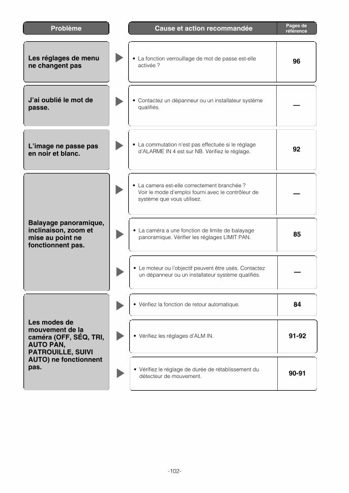
-102-
Les réglages de menune changent pas
• La fonction verrouillage de mot de passe est-elleactivée ?
96
J’ai oublié le mot depasse.
• Contactez un dépanneur ou un installateur systèmequalifiés. —
L’image ne passe pasen noir et blanc.
• La commutation n’est pas effectuée si le réglaged’ALARME IN 4 est sur NB. Vérifiez le réglage. 92
Balayage panoramique,inclinaison, zoom etmise au point nefonctionnent pas.
• La camera est-elle correctement branchée ? Voir le mode d’emploi fourni avec le contrôleur desystème que vous utilisez.
—
• La caméra a une fonction de limite de balayagepanoramique. Vérifier les réglages LIMIT PAN. 85
• Le moteur ou l’objectif peuvent être usés. Contactezun dépanneur ou un installateur système qualifiés. —
Les modes demouvement de lacaméra (OFF, SÉQ, TRI,AUTO PAN,PATROUILLE, SUIVIAUTO) ne fonctionnentpas.
• Vérifiez la fonction de retour automatique. 84
• Vérifiez les réglages d’ALM IN. 91-92
• Vérifiez le réglage de durée de rétablissement dudétecteur de mouvement. 90-91
Problème Cause et action recommandée Pages deréférence
WV-CS954_FR 09.1.21 2:55 PM ページ102

-103-
La gaine du câbled’alimentation estendommagée.
• Le câble d’alimentation, le connecteur ou la prise sont endommagés.Il y a risque d’électrocution et d’incendie à continuer à les utiliser.Débranchez immédiatement le câble d’alimentation et contactez undépanneur ou un installateur système qualifiés.
Le cordon d’alimentationchauffe pendant lefonctionnement.
Le câble d’alimentationdevient tiède ou chaudlorsqu’il est plié ou tiréen cours defonctionnement.
● Vérifier régulièrement le cordon d’alimentation.
Le réglage de mode demouvement de lacaméra (OFF, SÉQ, TRI,AUTO PAN,PATROUILLE, SUIVIAUTO) change.
• Vérifiez la fonction de retour automatique. 84
La position de lacaméra est différentede la position préréglée
• Faites RAFRAICHIR à partir du menu de réglagespécial. 94
L’image est différentepar rapport au réglagede position.
• Ajustez l’image avec le menu préréglé et un fichier descène. 82-83
La partie supérieure del’image est noire lorsquela caméra est enorientation horizontale.
• Cela vient du couvercle interne de la caméra. Cecin’indique pas un dysfonctionnement. 89
La caméra commencetoute seule un balayagepanoramique.
• Si la fonction de nettoyage est activée, ceci est normalet n’indique pas de dysfonctionnement. Vérifiez lesréglages de NETTOYAGE.
89
• Si la fonction nettoyage est désactivée, ce symptômepourrait être dû à du bruit. 60, 63
Problème Cause et action recommandée Pages deréférence
WV-CS954_FR 09.1.21 2:55 PM ページ103

-104-
● GénéralPuissance requise 24 V CA, 60 Hz
Puissance consommée 13 W
Dispositif de prise de vue Capteur CCD 1/4" à transfert d’interligne
Pixels effectifs 768 (H) × 494 (V)
Zone de balayage 3,65 mm (H) × 2,74 mm (V)
Signal NTSC
Synchronisation Interne (INT)/ signal de commande multiplexé (VD2)/source d’alimentation (SECTEUR)
Balayage Entrelacement 2:1
Fréquences de balayage Horizontale : 15,734 kHz, Verticale : 59,94 Hz
Sortie vidéo VBS : 1,0 V [P-P]/75 Ω (prise BNC)
Résolution (Centre) Horizontale: 480 lignes minimum (couleur mode NORMAL)
540 lignes typ.,520 lignes minimum (couleur mode ÉLEVÉ)
570 lignes minimum (noir et blanc)
Verticale : 350 lignes minimum (Centre)
Éclairage minimum 0,5 lux{fc} (mode couleur) 0,04 lux{fc} (mode noir et blanc) VISION NUIT : OFF; CAG : ÉLEVÉ
Gamme dynamique 52 dB typ. (SUPER-D3: OUI)
Rapport S/N 50 dB minimum (CAG: OFF)
Température ambiante de fonctionnement -10 °C à +50 °C (moins de +35 °C recommandé) ; Humidité 90 % max. (non condensation)
Dimensions 154.5 mm(P) × 233 mm(H) {6-5/64"(P) × 9-11/64"(H)}
Poids Environ 2,2 kg {4,9 lbs}
Finition Caméra video : Aluminium moulé avec un revêtement de mélanine (Couleur de peinture : Argent fin)
Dôme: Résine acrylique transparente
● Pan/AzimuthLimite de balayage panoramique 360°, infini
Modes de balayage panoramique Manuel, auto, position manuelle, position séquentielle
Vitesse de balayage panoramique* Manuel : Environ 0,065 °/s à 120 °/s 8 pas, 16 pas, 64 pas Préréglé : Environ 400 °/s
Limites d’inclinaison -5 °à 185 °(horizontale - verticale - horizontale) (selon l’angle d'inclinaison ANGLE AZIMUTH)
Modes d’inclinaison Manuel, position manuelle, position séquentielle
Vitessse d’inclinaison* Manuelle : Environ 0,065 °/s à 120 °/s 8 pas, 16 pas, 64 pas Préréglée : Environ 400 °/s
● ObjectifRapport zoom 30x (Environ 300x avec zoom numérique)
Longueur focale 3,8 mm à 114 mm
Rapport d’ouverture maximum 1:1,4 (WIDE) à 3,7 (TELE)
Distance de l’objet 1,5 m
Limites de réglage de diaphragme F1,4 à 22, Close
Champ angulaire d’observation Horizontal : 1,9 ° (TELE) à 52 ° (WIDE) Vertical : 1,4 ° (TELE) à 40 ° (WIDE)
CARACTÉRISTIQUES TECHNIQUES
* La vitesse réelle dépend du type de contrôleur utilisé.
WV-CS954_FR 09.1.21 2:55 PM ページ104

-105-
● Fonctions principalesInterface contrôleur Système coaxial multiplex, RS485
Fonctions de contrôle Balayage panoramique et inclinaison, zoom et mise au point, 256 positionspréréglées, position d’origine, patrouille
CAG OUI (BAS), OUI (MOYEN), OUI (ELEVE), OFF
Titre (ID) OUI, OFF (ID préréglée, ID caméra, titre de zone : 16 caractères alphanumériques)
Vitesse zoom Environ 6,0 secondes (TELE à WIDE) en mode manuel
Limite de réglage de zoom 1x à 300x (plus de 30x zoom numérique)
Verrouillage mot de passe Tous menus
Mise au point auto MANUEL/AUTO (lié PAN, AZIMUTH, ZOOM)
Diaphragme ALC (Niveau cible OUV/FERMER réglable)/MANUEL
Obturateur OFF (1/60), AUTO, 1/100, 1/250, 1/500, 1/1000, 1/2000, 1/4000, 1/10000
Accroissement de la sensibilité électronique 32X max. (AUTO ou FIXE)
Mode automatique OFF, SÉQ, TRI, AUTO PAN, PATR, SUIVI AUTO
Touche balayage panoramique SÉQ, TRI, AUTO PAN, PATR, SUIVI AUTO
Digital Flip (retournement numérique) OUI/OFF
SUPER-D3 OUI/OFF
Détecteur de mouvement OFF/MODE1/MODE2
Entrée/sortie d’alarme 4 entrées (ALM IN 1 à ALM IN 4) 2 sorties (ALARME/AUX1, NB/AUX2)
Basculement en mode noir et blanc AUTO/OUI/OFF
Zone de confidentialité OUI/OFF (8 réglages de zone)
Patrouille STOP/LECTURE/MÉMORISATION
Nettoyage OUI/OFF
Maintien d’image OUI/OFF
Stabilisateur d’images automatique OUI/OFF
Réglage de sélection de scène INTERIEUR (-) /INTERIEUR (+) /EXTERIEUR (-) /EXTERIEUR (+)
Réglage de langue Japonais, anglais, allemand, français, italien, espagnol, russe, chinois
WV-CS954_FR 09.1.21 2:55 PM ページ105

-106-
WV-CS954_FR 09.1.21 2:55 PM ページ106

-107-
WV-CS954 Cover(1-4) tan 09.1.30 6:29 PM ページ107

Printed in ChinaAs0109-1010 3TR003278HZA Imprimé en Chine