model no.nn-sg636 cth nn-sg656s cth -...
TRANSCRIPT

Microwave Oven
Model No.
© Panasonic Corporation 2015 Unauthorizedcopying and distribution is a violation of law
Order No.
Specifications
Power Requirement
Power Output
Microwave Frequency
Magnetron
Timer
Outside Dimensions
Cavity Dimensions
Net Weight
Shipping weight
Specifications subject to change without notice.
Single phase, 3 wire grounded
2,450 MHz
2M248J
Volts ~ AC 60 Hz
16kg (approx.)
18kg (approx.)
351(W) x 249(H) x 386 (D) mm
1201500 Watts (
1100 Watts full microwave power (IEC60705)
5 (W) x (H) x 410(D) mm19 315
13.5 A)
Max.30 min (P10) Max.99 (Other Power level) 99min sec
NN-SG636 CTH
1.3 cu.ft
Canada
S
NN-SG656 CTHS
Stainless
PCI160300 CEEI
3

Your 国rety and the sarety of others are very important
We ha帽 provided ImporIant safety messages in 酌is manual a r回 on your appliance. Always read and obey 副1 sa~副y messages
A This is I tJe sa阳Iy .rt aymbol 11 is us回 t口 ."'" ,凶 '0 0町o、幅dnual haz,r也阳t国n kilt 回 h"MWtAyR恤N, and o晴、.,且The safety m essages w ill 101阳w the S81ety alert sym bol and ei酌e r I t回 word "DANGER". "WARNING~ Of ''CAUT阳Wn胃sewor咽"γ晤M'
~ DANOER YO" 国内 be.蜘00' 槌『阳,lly Injure<l if yOl.l don'1 !mn回<:I I8to. Iv '0阳w irlSlruet阳".
~ WARNIN。 You can be killed or ...而OUllty Inj ured if y且, don'l foNow insl rucl ionll
~ CAUTION Y由J can be axp圃ed 10 a pol回tJally hazard国且由uallon whlch. if nol avoid田, may fesutt In mlnor 町m回扣帽le Injury,
The salely 世咽mHs'aEgUed-i w ,tl t耐归。 whøl lhe polenlløl høvord i.. le ll yoo how 10 re<lu面址、. d田,田e of injury. ønd lalyou what cøn ha阿>enll rtlelnstructior晤 are nol tollow咽d
& WAR N ING
\ . T hls prodl皿 should be servi咽<:1 only by tr/lllned. qua lifl回 personn酬
2. Though 酌is prodlJCt hais been manulactured in ∞mpliunce 町响'
MFecleraJ Petlorma町EI Star回ard 2 1 CFR Sotx:l'咽pter J"(O.H .H ,曰: U,S.A, models 口r 幽A.d国tbn Emtm『a咱tl DeVEesAct-it相'alth and Wellarl! Canada): Ganadian modols it is ve叩 important all rep.;!"s should be made in acco咽a~砸回Ih procedures described in I t.is manuallo avoid being I! ~posed 10 e1<<:回副..m比拍.wave r&<li酬。o.
3. Chock for rOdiot晤o 崎恤且由e before or回 oller e呻叩,.~悔旷咱 00四rding to the "pro国dure for meo..uri吨 rodio.tion 崎oI<o.ge."
4. 11 the unit C4l'lnol be repalr&d on site. acMse the customer nol lO use until unil ls repaired. 5. A n y servlceman w ho leams 01 any accidenl pertaln lng to m lcrowave radlallon 阳akage Including the 口ven operat lng wi lh
open d四f 吉hould immediately no l il y the appropriate address 1;5阳d below and Cente. lor Dev咽s and Radiolog昭al Health . DHHS
IN U.SA AN口 PlIMsonÎC Corpa'lIIÎO罚。' "咀r1h ArlW'lClI IN CANADA panason昭 Car\ada loc. PUERTO RICO Two Riverlront PløZ9 (PCI) 5770 Arr也幅, 0,闸 . Mlss恒sauga.
(PNA) Newo.r1I. NJ 07102 OntariO. L4W2T3 AI\e.、U咽,. Tec阳、目.0 1 Holl ine (905阳24 -501 0归国)572_2672
6. There are Gpeclal c白mponliln l G usad 11"1 the rT首crowave oven whlch a ra Imporlanllor lIa l a l y. Thege p a r19 a ra markad w llh a Lh on lhe replacemenl parts 1 ;剖 , H js essenHa l that these crule-lpar1s shouM be replaced on1ly n wtth the m anufacture'S speci lied parlS 10 prevenl micr口wave leakage. shock.li帽. 0 ' o lher hazards. Do r田t modil y Ihe orginal de岳go.
PRECAUTIONS TO BE OBSERVED BEFORE AND DURING SERVICING TO AVOID POSSIBLE EXPOSURE TO EXCESSIVE MICROWAVE ENERGY (A ) Do nOI operala 01 allow the oven 10 be operalQd wlth the Inspec:t1on Wil h1n lha m盹附,wave generatlng COIl1PSr1叫"'0回.
door open ched<; thø magnølron. waveguide or transmission Ilne . and 6 Make the 10110'明吨 saletyc陶cks 00 a ll 口.~暗 10 be serviced "叫y for prope' al;gnmenl , inlegrity and connect白~.
""0," 前甘v;;llÎ吨 ~. "可gnelron or other microwave回""四. (D) Any曲feçtive 0' m'5ad阳刷刷回m阳"enl~ in Ihe inler1ock. and make r,饵抽'fS as necessary : monitor. 曲o. seal. and mÎσ.owave gene.剧'01"1 a咽 t'8ns.
(1) Inta r10ck 呵>eratlon mlsslon sysTems shall be rapalred. replac田. or adJusted i2) Proper 曲唱"'~到og 国"出国uresde缸rÎb回 In Ihls manual belore Ihe 刷刷"(3) Seal and 8ealing surlace s (arclng. weaf . and olh匾, released 10 1I咽。恻、".
damage) (E ) Am比'0附..阳k啕e check 10 verlfy ∞mpliance WÎth Ihe (4) Damage 10 or Ioosenl吨。,1 hlr咱帕 西.. 阳"".. Federal Pertormal'lC8 Slandard 圳、OU IO be pertorm ecl on (5) Evidence 01 d.o阳"" 日",,"皿 each oven prior 10 release 10 Ihe o wne.
(C)B酬。咱 Iu.m吨。om尼rowave阳Wef lor 8ny servl(:串闹剧。,
&CAUTI O N About lelKf free salde r (PbF)
Dl s tlncUon 01 PbF PC8 : PC Bs (manulaclured) using lead I ree soIde. will ha'四 a PbF sla mp ofl Ihe PCB C a utlon : • Pb Iree sok旬r hasa h咱国r melting poÎn l than sta.回ard soIder: Typically Ihe m刨Tîngp但时 is 30 - 40-C h国国『
Ploasø uso a hlgh lemporalure soldoring IrOfl. In cose 0 1 tho soldaring Iron wi lh temparalure c刷吼,时. ple08C国t
1110370 ::t: 10 ' C • Pb l røe sok阳 will l end to sp陆目、 wtlan heated I∞ h咱h (aOOu l 6∞.C) . Use 自y唱warl! proleclioo

(Page)
SAFETY PRECAUTIONS - - - - - - - - - - - - - - - - - - - - - - - - - - - - - - - - - - - - - - - - - - - - - - - - - - - - - - - - - - - - - - - - - - - - - Inside front cover
POWER LEVEL & ACCESSORIES - - - - - - - - - - - - - - - - - - - - - - - - - - - - - - - - - - - - - - - - - - - - - - - - - - - - - - - - - - - - - - - - - - - - - - - - - - - - - 1-1
CAUTIONS - - - - - - - - - - - - - - - - - - - - - - - - - - - - - - - - - - - - - - - - - - - - - - - - - - - - - - - - - - - - - - - - - - - - - - - - - - - - - - - - - - - - - - - - - - - - - - - - - - - - - - - - - - - - - - 2-1
INSTALLATIONS - - - - - - - - - - - - - - - - - - - - - - - - - - - - - - - - - - - - - - - - - - - - - - - - - - - - - - - - - - - - - - - - - - - - - - - - - - - - - - - - - - - - - - - - - - - - - - - - - - - - - - 3-1
OPERATING INSTRUCTIONS - - - - - - - - - - - - - - - - - - - - - - - - - - - - - - - - - - - - - - - - - - - - - - - - - - - - - - - - - - - - - - - - - - - - - - - - - - - - - - - - - - - - 4-1
FEATURES- - - - - - - - - - - - - - - - - - - - - - - - - - - - - - - - - - - - - - - - - - - - - - - - - - - - - - - - - - - - - - - - - - - - - - - - - - - - - - - - - - - - - - - - - - - - - - - - - - - - - - - - - - - - - - - - - - - - - - - - 4-1
CONTROL PANEL - - - - - - - - - - - - - - - - - - - - - - - - - - - - - - - - - - - - - - - - - - - - - - - - - - - - - - - - - - - - - - - - - - - - - - - - - - - - - - - - - - - - - - - - - - - - - - - - - - - - - - - - - - - - - - 4-1
OPERATING SEQUENCE- - - - - - - - - - - - - - - - - - - - - - - - - - - - - - - - - - - - - - - - - - - - - - - - - - - - - - - - - - - - - - - - - - - - - - - - - - - - - - - - - - - - - - - - - - - - - - - - - - - - 4-2
SCHEMATIC DIAGRAM - - - - - - - - - - - - - - - - - - - - - - - - - - - - - - - - - - - - - - - - - - - - - - - - - - - - - - - - - - - - - - - - - - - - - - - - - - - - - - - - - - - - - - - - - - - - - - - - - - - - - - 4-4
CIRCUIT DESCRIPTION - - - - - - - - - - - - - - - - - - - - - - - - - - - - - - - - - - - - - - - - - - - - - - - - - - - - - - - - - - - - - - - - - - - - - - - - - - - - - - - - - - - - - - - - - - - - - - - - - - - - - 4-5
SERVICE INFORMATION - - - - - - - - - - - - - - - - - - - - - - - - - - - - - - - - - - - - - - - - - - - - - - - - - - - - - - - - - - - - - - - - - - - - - - - - - - - - - - - - - - - - - - - - - - 5-1
TOOLS AND MEASURING INSTRUMENTS - - - - - - - - - - - - - - - - - - - - - - - - - - - - - - - - - - - - - - - - - - - - - - - - - - - - - - - - - - - - - - - - - - - - - - - - - - - 5-1
MICROWAVE LEAKAGE TEST - - - - - - - - - - - - - - - - - - - - - - - - - - - - - - - - - - - - - - - - - - - - - - - - - - - - - - - - - - - - - - - - - - - - - - - - - - - - - - - - - - - - - - - - - - - - 5-1
MEASUREMENT OF MICROWAVE POWER OUTPUT - - - - - - - - - - - - - - - - - - - - - - - - - - - - - - - - - - - - - - - - - - - - - - - - - - - - - - - - - - - 5-3
DISASSEMBLY AND ADJUSTMENT - - - - - - - - - - - - - - - - - - - - - - - - - - - - - - - - - - - - - - - - - - - - - - - - - - - - - - - - - - - - - - - - - - - - - - - - - - - - - - - - - - - - - 5-3
INTERLOCK CONTINUITY TEST- - - - - - - - - - - - - - - - - - - - - - - - - - - - - - - - - - - - - - - - - - - - - - - - - - - - - - - - - - - - - - - - - - - - - - - - - - - - - - - - - - - - - - - - - - 5-7
COMPONENT TEST PROCEDURE - - - - - - - - - - - - - - - - - - - - - - - - - - - - - - - - - - - - - - - - - - - - - - - - - - - - - - - - - - - - - - - - - - - - - - - - - - - - - - - - - - - - - - 5-8
TROUBLE SHOOTING - - - - - - - - - - - - - - - - - - - - - - - - - - - - - - - - - - - - - - - - - - - - - - - - - - - - - - - - - - - - - - - - - - - - - - - - - - - - - - - - - - - - - - - - - - - - - - - - - - - - - - 5-12
CONTENTS
EXPLODED VIEW - - - - - - - - - - - - - - - - - - - - - - - - - - - - - - - - - - - - - - - - - - - - - - - - - - - - - - - - - - - - - - - - - - - - - - - - - - - - - - - - - - - - - - - - - - - - - - - - - - - - - 6-1
REPLACEMENT PARTS LIST - - - - - - - - - - - - - - - - - - - - - - - - - - - - - - - - - - - - - - - - - - - - - - - - - - - - - - - - - - - - - - - - - - - - - - - - - - - - - - - - - - - - 7-1
SCHEMATIC DIAGRAM OF P.C.B. - - - - - - - - - - - - - - - - - - - - - - - - - - - - - - - - - - - - - - - - - - - - - - - - - - - - - - - - - - - - - - - - - - - - - - - - - - - - - - 8-1

1-1
POWER LEVEL & ACCESSORIES
This microwave oven is designed for household use only.
It is not recommended for commercial purposes.
DESCRIPTIONMicrowave Power for Variable Cooking
Power level
ITEMControl Complement
Rating Label Location
Accessories
Glass Traygnirell R oR
Inside
High
Defrost
Medium
Med
Low
1100 Watts750 Watts550 Watts
300 Watts150 Watts
• DO NOT operate on a 2-wire extension cord duringrepair and use.
• NEVER TOUCH any oven components or wiring duringoperation.
• BEFORE TOUCHING any parts of the oven, alwaysremove the power plug from the outlet.
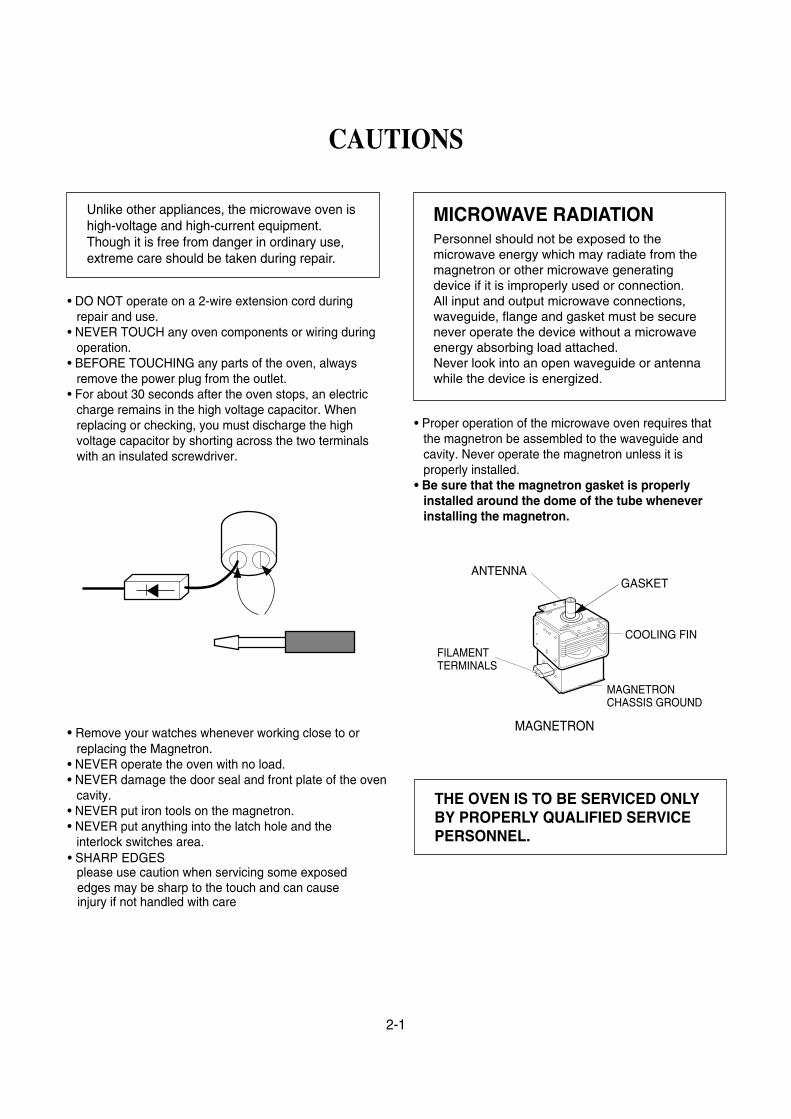
• For about 30 seconds after the oven stops, an electriccharge remains in the high voltage capacitor. Whenreplacing or checking, you must discharge the highvoltage capacitor by shorting across the two terminalswith an insulated screwdriver.
• Remove your watches whenever working close to orreplacing the Magnetron.
• NEVER operate the oven with no load.• NEVER damage the door seal and front plate of the oven
cavity.• NEVER put iron tools on the magnetron.• NEVER put anything into the latch hole and the
interlock switches area.
• Proper operation of the microwave oven requires thatthe magnetron be assembled to the waveguide andcavity. Never operate the magnetron unless it isproperly installed.
• Be sure that the magnetron gasket is properlyinstalled around the dome of the tube wheneverinstalling the magnetron.
2-1
CAUTIONS
Unlike other appliances, the microwave oven ishigh-voltage and high-current equipment.Though it is free from danger in ordinary use,extreme care should be taken during repair.
THE OVEN IS TO BE SERVICED ONLYBY PROPERLY QUALIFIED SERVICEPERSONNEL.
MICROWAVE RADIATIONPersonnel should not be exposed to themicrowave energy which may radiate from themagnetron or other microwave generatingdevice if it is improperly used or connection.All input and output microwave connections,waveguide, flange and gasket must be securenever operate the device without a microwaveenergy absorbing load attached.Never look into an open waveguide or antennawhile the device is energized.
ANTENNA
COOLING FIN
MAGNETRONCHASSIS GROUND
FILAMENTTERMINALS
MAGNETRON
GASKET
• SHARP EDGESplease use caution when servicing some exposededges may be sharp to the touch and can cause injury if not handled with care

INSTALLATIONS
3-1
INSTALLING1. Empty the microwave oven and clean inside it with
a soft, damp cloth. Check for damage such asmisaligned door, damage around the door or dentsinside the cavity or on the exterior.
2. Put the oven on a counter, table, or shelf that isstrong enough to hold the oven and the food andutensils you put in it. (The control panel side of theoven is the heavy side. Use care when handling.)
3. Do not block the vent and the air intake openings.Blocking vent or air intake openings can causedamage to the oven and poor cooking results.Make sure the microwave oven legs are in place toensure proper air flow.
4. The oven should not be installed in any area whereheat and steam are generated, because they maydamage the electronic or mechanical parts of theunit.Do not install the oven next to a conventionalsurface unit or above a conventional wall oven.
5. Use microwave oven in an ambient temperatureless than 104°F(40°C).
6. Place the microwave oven on a sturdy and flatsurface at least 10 cm(4 inches) from the wall.
7. Place the microwave oven as far away as possiblefrom TV, RADIO, COMPUTER, etc., to preventinterference.
EARTHING INSTRUCTIONSThis microwave oven is designed to be used in a fullyearthed condition.It is imperative, therefore, to make sure it is properlyearthed before servicing
WARNING-THIS APPLIANCEMUST BE EARTHED
IMPORTANT
As the colors of the wires in the mains lead of thisappliance may not correspond with the coloredmarkings identifying the terminals in your plug,proceed as follows.
The wire which is colored greenconnected to the terminal in the plug which is markedwith the letter E or by the earth symbol ( ) orcolored green or green-and-yellow.
The wire which is colored the terminal in the plug which is marked with the letterN or colored
The wire which is colored to the terminal in the plug which is marked with theletter L or colored .
BEFORE YOU BEGIN, READ THE FOLLOWING INSTRUCTIONS COMPLETELY AND CAREFULLY.
10cm
The wires in this mains lead are colored inaccordance with the following code:
Green: EarthWhite: NeutralBlack: Live
must be
white must be connected to
.
black must be connected
black
white

4-1
Location of Controls
1 External Air Vent 2 Internal Air Vent 3 Door Safety Lock System 4 Exhaust Air Vent
21 Auto Defrost Pad (See page 11)
22 Keep Warm Pad (See page 10) 23 Quick 30 Pad (See page 10)
Stop/Reset Pad is pressed once during oven operation, Start Pad must be pressed again to
5 Control Panel 6 Identification Plate
24 More Pad 25 Less Pad
(See page 10) (See page 10)
restart oven.
7 Glass Tray 8 Roller Ring 9 Heat/Vapor Barrier Film
(do not remove) 10 Waveguide Cover
(do not remove) 11 Door Release Button 12 Warning label 13 Menu label 14 Power Supply Cord 15 Power Supply Plug 16 Display Window 17 Popcorn Pad (See page 10) 18 Sensor Reheat Pad
(See page 12) 19 Sensor Cook Pad (See page 12)
20 Power level Pad (See page 8)
26 Number Pads 27 Timer Pad
(See page13)
28 Clock Pad (See page 8)
29 Stop/Reset Pad Before cooking: One tap clears all your instructions. During cooking: one tap temporarily stops the cooking process. Another tap cancels all your instructions, and time of day or colon appears in the display window.
30 Start Pad After cooking program setting, one tap allows oven to begin functioning. If door is opened or
Beep Sound: When a pad is pressed correctly, a beep will be heard. If a pad is pressed and no beep is heard, the unit did not or cannot accept the instruction. When operating, the oven will beep twice between programmed stages. At the end of any complete program, the oven will beep 5 times. NOTE: If no operation after cooking program setting, 6 minutes later, the oven will automatically cancel the cooking program. The display will return to clock or colon display.
16
17
2021
23
26
27
29
18
19
22
28
2425
30
➀➃
➆
➇
11
12 14
15
12 ➉ ➁➈
➂
➄
➅➂13

OPERATING SEQUENCE
4-2
Sensor cookingAuto sensor cooking without setting a power level or selectinga time. All that is necessary is to select an Auto SensorProgram before starting to cook.Understanding Auto Sensor Cooking
As the food cooks, a certain amount of steam is produced.If the food is covered, this steam builds up and eventuallyescapes from the container. In Auto Sensor Cooking, acarefully designed instrument, called the steam sensorelement, senses this escape of steam. Then, based uponthe Auto Sensor Program selected, the unit willautomatically determine the correct power level and theproper length of time it will take to cook the food.
NOTE:Auto Sensor Cooking is successful with the foods andrecipes found in the Auto Sensor Cooking Guide.Because of the vast differences in food composition,items not mentioned in the Cooking Guide should beprepared in the microwave oven using power selectand time features. Please consult Variable PowerMicrowave Cookbook for procedures.
The following is a description of component functionsduring oven operation.
1. SETTING THE CLOCK
NOTE: Clock is a 12-hour display.
• Press twice.Colon will blink in the display window.
2. CANCEL FUNCTIONTouch the Stop/Reset pad whenever you need tocancel an entry or a function currently in use.The display will either return to the last item enteredor to the clock.
Stop/Reset
Stop/Reset
Timer/Clock
Timer/Clock
Set the timeby pressing
Desiredcooking time
Desiredcooking power Start
3. MICROWAVE COOKING
time pads
This oven has a CHILD LOCK feature • TO SET CHILD LOCK
• Press start pad three timesappear in the display.
• TO CANCEL CHILD LOCK• Press stop/reset pad three times
disappears.
Stop/Reset
Select the weight
of foodStart
4. TURBO DEFROST
5. CHILD LOCK

Explanation of the Auto Sensor Cooking process 1. During the first 10 second period there is no microwave
activity. When calculating the T2 time by using theformula below make sure this 10 seconds is subtractedfrom the T1 time. In other words, T1 time starts at theend of the 10 second period.
2. T1 time The total amount of time it takes the microwaveoven to switch to T2 time after the 10second period.
3. T2 time When the steam escapes from the cookingcontainer placed in the oven, the steam sensor detectsit and the microprocessor calculates the balance ofcooking time. This T2 time is then shown in the displayand begins counting down.Balance of cooking time (T2 time)The balance of cooking time which is called T2 time,can be calculated by the following formula.T2 time (in sec.) = T1 time X K factor
NOTE:Remember, the T1 time starts after the 10 secondperiod. The coefficient K is programmed into themicroprocessor memory and they are listed in thefollowing tables along with the P1 and P2 powers.
NOTE:When "More" or "Less" pad is selected, the K factorvaries resulting in T2 time to be increased or decreased.
Example of calculating the T2 timeExample 1: If the T1 time is measured to be 2 minutes and40 seconds after the 10 second period.T2 = T1 × K= 2 min. and 40 sec. × 1.1= 160sec. × 1.1= 176 sec.
Category P1Power
P2Power
K FactorStandard
Frozen Entrees Power Level P6 Power Level P7 0.5
Sensor reheatAuto Sensor Reheat is a quick and easy way to reheatrefrigerated and room temperature foods.Simply press the reheat pad. There is no need to select powerlevel and cooking time.NOTE:
The Auto Sensor Reheat process is similar as Auto SensorCooking process.
Balance of cooking time (T2 time)The balance of cooking time which is called T2 time, can becalculated by the following formula.T2 time (in sec.) = T1 time X K factorNOTE:
Remember, the T1 time starts after the 10 second period.The coefficient K is programmed into the microprocessormemory and they are listed in the following tables alongwith the P1 and P2 powers.
NOTE:When "More" or "Less" pad is selected, the K factor variesresulting in T2 time to be increased or decreased.
Example of calculating the T2 timeExample 1: If the T1 time is measured to be 2 minutes and40 seconds after the 10 second period.T2 = T1 × K= 2 min. and 40 sec. × 1.1= 160sec. × 1.1= 176 sec.
Category P1Power
P2Power
K FactorStandard
Sensor Reheat Power Level P10 Power Level P6 0.2 or 0.4
Steam sensor and digitalprogrammer circuit
In order to determine if the steam sensor function of the digitalprogrammer circuit is working, do the following test. 1. Place a water load (100 cc) in the oven. 2. Tap Sensor Reheat pad. 3. Tap Start pad. 4. Steam Sensor detects steam about 1.5 to 2 minutes after
the Start pad is tapped. 5. T1 time cooking automatically switches to remaining time
for cooking (T2). 6. The remaining cooking time (T2) appears in display
window. If the following cooking time appears, SteamSensor function is normal.
T1 TIME T2 TIME (Remaining cookingtime)
50 Sec. ~ 2 Min. 0 Sec. ~ 24 Sec.
4-3

SCHEMATIC DIAGRAM
4-4

CIRCUIT DESCRIPTIONGENERAL DETAILS• The low voltage transformer supplies the necessary
voltage to the micom controller when power cord isplugged in.
• When the door is closed, the primary switch is ON, thesecondary switch is ON, and the monitor switch opens(contact COM and NO).
WHEN SELECTING COOKING POWERLEVEL AND TIME• The micom controller memorizes the function you set.• The time you set appears in the display window.• Each indicator light turns on to indicate that the stage
has been set.
WHEN TOUCHING THE START PAD• The coil of the relay is energized by the micom
controller.• Power input is supplied to the high voltage transformer
through the fuse to the primary switch and relay 2.• Turntable rotates.
• Cooking time starts counting down.• 3.2 volts AC is generated from the filament winding of
the high voltage transformer. This 3.2 volts is applied tothe magnetron to heat the magnetron filament throughtwo noise-preventing choke coils.
• A high voltage of approximately 2100 volts AC isgenerated in the secondary of the high voltagetransformer which is increased by the action of the highvoltage diode and charging of the high voltagecapacitor.
• The negative 4000 Volts DC is applied to the filamentof the magnetron.
WHEN THE OVEN IS SET AT ANY LEVELEXCEPT MAXIMUM.• The micom controller controls the ON-OFF time of relay
2 by the applied signal to vary the average output
power of microwave oven as POWER LEVEL. (refer to page 1-1)
WHEN THE DOOR IS OPENED DURINGCOOKING• Both the primary switch and relay 2 are cut off primary
winding voltage of the high voltage transformer.• ON-OFF of relay 2 is coupled electrically with opening
and closing of the secondary switch.• When the door is opened, the secondary switch is
opened and when the door is closed, the secondaryswitch is closed.
• The cooking time stops counting down.• Relay stops functioning.• As the door is opened, if the contact of primary switch
and relay 2 and/or secondary switch fails to open, thefuse opens due to the large current surge caused bythe monitor switch activation, which in turn stopsmagnetron oscillation.
4-5
L
FUSE
TRANS-FORMER
RELAY 2
MICOM CONTROLLER
SECONDARYSWITCH
SWITCH
N
MONITORSWITCH
PRIMARY
MONITORSWITCH
L
FUSE
RELAY 2
MICOM CONTROLLER
SECONDARYSWITCH
PRIMARYSWITCH
N
• The fan motor rotates and cools the magnetron byblowing the air (coming from the intake on the
• The air is also directed into the oven to exhaust thevapor in the oven through the left side.
backplate).
TRANS-FORMER

CAUTIONS
• Be sure to check microwave leakage prior toservicing the oven if the oven is operative prior toservicing.
• The service personnel should inform themanufacture importer, or assembler of anycertified oven unit found to have a microwaveemission level in excess of 1 mW/cm2 and shouldrepair any unit found to have excessive emission levelsat no cost to the owner and should ascertain the causeof the excessive leakage. The service personnelshould instruct the owner not to use the unit until theoven has been brought into compliance.
• If the oven operates with the door open, the servicepersonnel should:- Tell the user not to operate the oven.- Contact the manufacturer.
• The service personnel should check all surface andvent openings for microwave leakage.
• Check for microwave leakage after every servicing.The power density of the microwave radiation leakageemitted by the microwave oven should not exceed
mW/cm2. Always start measuring of an unknown fieldto assure safety for operating personnel from radiationleakage.
MEASURING MICROWAVE ENERGYLEAKAGE• Pour 275±15cc of 20±5°C(68±9°F) water in a beaker
which is graduated to 600 cc, and place the beakeron the center of the turntable.
• Set the energy leakage monitor to 2450 MHz anduse it following the manufacturer's recommendedtest procedure to assure correct result.
• When measuring the leakage, always use the 2-inch (5cm) spacer supplied with the probe.
• Operate the oven at its maximum output.• Measure the microwave radiation using and
electromagnetic radiation monitor by holding theprobe perpendicular to the surface being measured
Move probe along shaded area
Probe scanning speedLess than 2.5 cm/sec( 1in/sec)
5-1
SERVICE INFORMATION
TOOLS AND MEASURING INSTRUMENTS
MICROWAVE LEAKAGE TEST
NECESSARY TOOLSTools normally used for TV servicing are sufficient.Standard tools are listed below.
• Diagonal pliers• Long nose pliers• • Flat blade screwdriver• Wrench (size 5mm)• Nutdriver (size 5mm)• Adjustable wrench• Soldering iron• Solder• Vinyl insulation tape• Polishing cloth
NECESSARY MEASURING INSTRUMENTS• TESTER(VOLTS-DC, AC., Ohmmeter)• Microwave survey meter
- Holaday HI-1500HI-1501
- Narda 81008200
• Inch scale• 600 cc non conductive material beaker (glass or plastic),
inside diameter: approx. 8.5 cm(31/2 in.)• Cylindrical and made of borosilicate glass vessel.
max. thickness: 3 mmoutside diameter: approx. 190mmheight: approx. 90mm
• Glass thermometer: 100°C or 212°F (1 deg scale)
Torx screwdriver
1

MEASUREMENT WITH OUTER CASEREMOVED• When you replace the magnetron, measure for
microwave energy leakage before the outer case isinstalled and after all necessary components arereplaced or adjusted.Special care should be taken in measuring thefollowing parts. (Circled area of below Fig.)- Around the magnetron- The waveguide
MEASUREMENT WITH A FULLYASSEMBLED OVEN• After all components, including the outer case, are fully
assembled, measure for microwave energy leakagearound the door viewing window, the exhaust opening,and air inlet openings.
• Microwave energy leakage must not exceed the valuesprescribed below.
NOTE: Leakage with the outer case removed less than5 mW/cm2
oven (Before the latch switch (primary) isinterrupted) with the door in a slightly openedposition-less than 2 mW/cm .2
NOTES WHEN MEASURING• Do not exceed meter full scale deflection.• The test probe must be removed no faster than
1 inch/sec (2.5 cm/sec) along the shaded area,otherwise a false reading may result.
• The test probe must be held with the grip portion of thehandle.A false reading may result if the operator's hand isbetween the handle and the probe.
• When testing near a corner of the door, keep the probeperpendicular to the surface making sure the probehorizontally along the oven surface, this may possiblycause probe damage.
RECORD KEEPING AND NOTIFICATIONAFTER MEASUREMENT• After adjustment and repair of any microwave energy
interruption or microwave energy blocking device,record the measured values for future reference. Alsoenter the information on the service invoice.
• The microwave energy leakage should not be morethan 1 mW/cm2
in good condition, functioning properly and genuinereplacement parts which are listed in this manual havebeen used.
• At least once a year, have the electromagnetic energyleakage monitor checked for calibration by itsmanufacturer.
WARNING : AVOID CONTACTING ANY HIGH VOLTAGE PARTS
5-2
after determining that all parts are
Leakage for a fully assembled

5-3
MEASUREMENT OF MICROWAVE POWER OUTPUT
• Microwave power output measurement is made withthe microwave oven supplied at its rated voltage andoperated at its maximum microwave power setting witha load of (1000±5) g of potable water.
• The water is contained in a cylindrical borosilicate glassvessel having a maximum material thickness of 3 mmand an outside diameter of approximately 190mm.
• The oven and the empty vessel are at ambienttemperature prior to the start of the test.
• The initial temperature (T1) of the water is (10±2)°C. Itis measured immediately before the water is added tothe vessel. After addition of the water to the vessel,the load is immediately placed on the center of theturntable which is in the lowest position and themicrowave power switched on.
• The time T for the temperature of the water to rise by avalue ∆ T of (10±2)°K is measured, where T is the timein seconds and ∆T is the temperature rise. The initialand final water temperatures are selected so that themaximum difference between the final watertemperature and the ambient temperature is 5°K.
4187 x (∆T) + 0.55 X (T2 - T0 ) X M
T
• T2: Temperature after heating• T0: Temperature of bowl• M: Weight of bowl
is measured while the microwave generator isoperating at full power. Magnetron filament heat-uptime is not included. (about 3 sec)
• The water is stirred to equalize temperature throughoutthe vessel, prior to measuring the final watertemperature.
• Stirring devices and measuring instruments areselected in order to minimize addition or removal ofheat.
WATER LOAD
TURNTABLE
P =
• The microwave power output P in watts is calculatedfrom the following formula :
NOTES:For simple tests of micromave power output, it by heating one litre water for one minute,minimum temperature rise should be 6 C
conduct
°
DISASSEMBLY AND ADJUSTMENTA. OUTER CASE REMOVAL
1) Disconnect the power supply cord from the outlet.2) Remove the screws from the rear and along side
edges of the case.The outer case must be moved backward to be liftedoff.
C. CONTROL PANEL ASSEMBLY
1) Disconnect the leadwire from the Timer motor2) Remove the screws for securing the control panel.3) Lift control panel ASS ’Y from the oven by the tab
unhooked.
B. POWER SUPPLY CORD
1) Remove the outer case.2) Disconnect two terminals, and remove one screw of
the earth terminal.
CAUTION: DISCHARGE THE HIGH VOLTAGE CAPACITOR BEFORE SERVICING
(refer to page 2-1)

5-4
D. DOOR ASSEMBLY REMOVAL1) Open the door.
CAUTION : Be careful not to damage Door Cby screwdriver.
3) Lift up and pull the door.
NOTE:1. After replacing the door, be sure to check that the
primary switch, monitor switch, and secondary switchoperate normally.
2. After replacing the door, check for microwave energyleakage with a survey meter. Microwave energy mustbe below the limit of 1 mW/cm2. (with a 275 ml waterload)
3. When mounting the door assembly to the ovenassembly, be sure to adjust the door assembly parallelto the chassis. Also adjust so the door has no playbetween the inner door surface and oven frameassembly. If the door assembly is not mountedproperly, microwaves may leak from the clearancebetween the door and the oven.
E. HIGH VOLTAGE TRANSFORMERREMOVAL
1) Discharge the high voltage capacitor.2) Disconnect the leadwire from magnetron, high voltage
transformer, and capacitor.3) Remove the screw holding the high voltage
transformer to the baseplate.
to the Cavity Ass'y.2) Remove two screws holding the Hinge
F. 1) Discharge the high voltage capacitor.2) Disconnect the leadwire from fan motor, noise filter
and high voltage capacitor.3) Remove the two screws holding the orifice
oven cavity and remove the high voltage earth screw.
4) Remove the screw of the capacitor bracket.5) Remove the two screws holding the fan motor ASS’Y
to the Orifice
G. HIGH VOLTAGE CAPACITOR ANDDIODE REMOVAL
ORIFICE
to the diode
ASSEMBLY REMOVAL
ASS’Y
.ASS’Y
1) Discharge the high voltage capacitor.2) Disconnect the leadwire from fan motor, noise filter
and high voltage capacitor.
earth screw.4) Remove the screw holding the high voltage capacitor
bracket.
3) Remove the screw holding the Orifice the oven
Remove door Assembly
Remove door Assembly

5-5
H. AIR GUIDE ASSEMBLY REMOVAL1) Disconnect the leadwire from lamp, A.C Relay and
monitor resistor and magnetron.2) Remove the screw to the cavity.
I. MAGNETRON REMOVAL1) Disconnect the leadwire from the high voltage
transformer and high voltage capacitor.2) Remove the air guide.3) Carefully remove the mounting screws holding the
magnetron and the waveguide.4) Remove the magnetron until the tube is
clear from the waveguide.
J. REMOVING THE TURNTABLE MOTOR1) Remove the .2) Remove the pully shaft VERY CAREFULLY 3) Lay the unit down on its back.4) Remove the turntable motor cover.
The turntable base cover is easily removed bypinching the six parts with a wire cutting.
5) Disconnect the leadwire from the turntable motorterminals.
6) Remove the screw securing the turntable motor tothe oven cavity ASS’Y
7) After rep the motor, rotate the removedturntable motor cover.
8) Fit the turntable motor cover’s projecting part to thebase plate slit.
glass tray
lacing
NOTE:1. Remove the wire lead from the turntable motor
VERY CAREFULLY.2. Be sure to grasp the connector, not the wires, when
removing
NOTE:1. When removing the magnetron, make sure its
dome does not hit any adjacent parts, or it may bedamaged.
magnetron.
2. When replacing the magnetron, be sure to installthe magnetron gasket in the correct position andbe sure that the gasket is in good condition.
3. After replacing the magnetron, check for microwaveleakage with a survey meter around themagnetron. Microwave energy must be below thelimit of 5 mW/cm2. (With a 275 ml. water load).Make sure that gasket is rigidly attached to the
To prevent microwave leakage, tighten themounting screws properly, making sure there is no gapbetween the waveguide and the magnetron.
Waveguide
MagnetronGasket
Magnetron
Dome
Waveguide Bracket
Magnetron
Base plate

K. PCB ASSEMBLY REMOVAL1) Remove the control panel assembly from the
cavity. 2) Remove screws which hold the PCB to
control panel.3) Disconnect the flat cable from the PCB
take off the PCB .
L. INTERLOCK SYSTEM1) INTERLOCK MECHANISM
The door lock mechanism is a device which hasbeen specially designed to eliminate completelymicrowave activity when the door is opened duringcooking and thus to prevent the danger resultingfrom the microwave leakage.
2) MOUNTING OF THE PRIMARY/MONITOR/SECONDARY SWITCHES TO THE LATCHBOARD
3) INSTALLATION AND ADJUSTMENT OF THELATCH BOARD TO THE OVEN ASSEMBLY
• Mount the latch board to the oven assembly.• Adjust the latch board in the arrow direction so that
oven door will not have any play in it when the dooris closed.
• Tighten the mounting screw.• Check for play in the door by pushing the door
release button. Door movement should be lessthan 0.5 mm. (1/64 inch)Don't push the door release button while makingadjustment. Make sure that the latch movessmoothly after adjustment are completed and thatthe screws are tight. Make sure the primary, monitor,and secondary switches operate properly byfollowing the continuity test procedure.
5-6
ADJUSTMENTDIRECTION
CAUTION: CHECK THE CORRECT POSITION
MAGNETRON
H.V. TRANSFORMER
PRIMARY
H.V. CAPACITOR
H.V.DIODE
FIG. 1
the
and
C
PRIMARYSWITCH
MONITORSWITCH
SECONDARYSWITCH

A. PRIMARY INTERLOCK SWITCH TESTWhen the door release button is depressed slowlywith the door closed, an audible click should beheard at the same time or successively atintervals. When the button is released slowly, thelatches should activate the switches with anaudible click.If the latches do not activate the switches whenthe door is closed, the switches should be aadjusted in accordance with the adjustmentprocedure. Disconnect the wire lead from theprimary switch. Connect the ohmmeter leads tothe common (COM) and normally open (NO)terminal of the switch. The meter should indicatean open circuit in the door open condition.When the door is closed, the meter shouldindicate a closed circuit.When the primary switch operation is abnormal,make the necessary adjustment or replace theswitch only with the same type of switch.
B. SECONDARY INTERLOCK SWITCH TESTDisconnect the wire lead from the secondaryswitch.Connect the ohmmeter leads to the common(COM) and normally open (NO) terminals of theswitch. The meter should indicate a open circuit inthe door open condition. When the door is closed,meter should indicate an closed circuit. When thesecondary switch operation is abnormal, make thenecessary adjustment or replace the switch onlywith the same type of switch.
C. MONITOR SWITCH TESTDisconnect the wire lead from the monitor switch.Connect the ohmmeter leads to the common(COM) and normally closed (NC) terminals of theswitch. The meter should indicate closed circuit inthe door open condition. When the door is closed,meter should indicate an open circuit. When themonitor switch operation is abnormal, replace withthe same type of switch.NOTE: After repairing the door or the interlocksystem, it is necessary to do this continuitytest before operating the oven.
5-7
WARNING : FOR CONTINUED PROTECTION AGAINST EXCESSIVE RADIATION EMISSION, REPLACE ONLY WITH IDENTICAL REPLACEMENT PARTS.
COMPONENTS TEST PROCEDURE RESULTS
SWITCHES Check for continuity of the Door Door(Wire leads removed) switch with an Ohm-meter open closed
PrimarySwitch
MonitorSwitch
NOTE : After checking for the continuity of switches, make sure that arecorrectly connected.
COMNO
COM
NC
COMNO
INTERLOCK CONTINUITY TEST
SecondarySwitch
TYPE NO. KW3A FOR SWITCHS
Type No.KW3A
Type No.KW3A
Type No.KW3A

5-8
CAUTIONS1. DISCONNECT THE POWER SUPPLY CORD FROM THE OUTLET WHENEVER REMOVING THE
OUTER CASE FROM THE UNIT. PROCEED WITH THE TEST ONLY AFTER DISCHARGING THE HIGHVOLTAGE CAPACITOR AND REMOVING THE WIRE LEADS FROM THE PRIMARY WINDING OF THEHIGH VOLTAGE TRANSFORMER. (SEE PAGE 2-1)
2. ALL OPERATIONAL CHECKS WITH MICROWAVE ENERGY MUST BE DONE WITH A LOAD (1 LITEROF WATER IN CONTAINER) IN THE OVEN.
COMPONENTS TEST PROCEDURE RESULTSHIGH VOLTAGETRANSFORMER(Wire leads removed)
MAGNETRON(Wire leads removed)
1. Measure the resistance.(Ohm-meter scale: Rx1)• Primary winding• Secondary winding• Filament winding
2. Measure the resistance.(Ohm-meter scale: Rx1000)• Primary winding to ground• Filament winding to ground
1. Measure the resistance.(Ohm-meter scale: Rx1)• Filament terminal
2. Measure the resistance.(Ohm-meter scale: Rx1000)• Filament to chassis
Approx.: 1.4 ohmApprox.: 90 ohmLess than: 1 ohm
Normal: InfiniteNormal: Infinite
Normal: Less than 1 ohm
Normal: Infinite
COMPONENT TEST PROCEDURE
PRIMARY TERMINAL
SECONDARY WINDING
FILAMENT WINDINGTERMINAL

5-9
COMPONENTS TEST PROCEDURE RESULTS
HIGH VOLTAGECAPACITOR
HIGH VOLTAGEDIODE
Measure the resistance.(Ohm-meter scale: Rx1000)• Terminal to terminal.
Measure the resistance.(Ohm-meter scale: Rx1000)• Terminal to case.
Measure the continuity (Forward).(Ohm-meter scale: Rx10000)
Measure the continuity (Reverse).(Ohm-meter scale: Rx10000)
Normal: Momentarily indicatesseveral ohms, and thengradually returns to
Normal:
Normal: Abnormal: Continuity.
NOTE: When testing the magnetron, be sure to install the magnetron gasketin the correct position and be sure that the gasket is in good condition.
Antenna
Gasket
Chassis
Filament
10M ohms.
NOTE :Some inexpensive metersmay indicate infiniteresistance in both direction.
*
Normal: Continuity.Abnormal: *

5-10
COMPONENTS TEST PROCEDURE RESULTS
1 3 5
Relay 2
Relay 1
FUSE
THERMALCUT-OUT
RELAY 2 OF P.C.B.(Wire leads removed.)Note: RelayRelay 1: Fan motor
Turntable motorOven lamp
Relay 2: Microwave
Check for continuity of the fuse with anmulti-meter.
NOTE: If the fuse is blown, check the primary, the secondary, and the monitor switches,H.V.D. and H.V.C. before replacing the fuse.If the fuse is blown by improper switch operation replace the defective switch and thefuse at the same time. Replace just the fuse if the switches operate normally.
Check for P.C.B. connector.
Normal Abnormal
Cooking Start OFF
Below specifiedtemperature
specifiedtemperature
Above
L.V.Transformer of P.C.BDisconnect the 3 pinconnector from P.C.B.
*Normal Abnormal
(Refer to schemetic diagram)
Normal Normal
Normal Normal

5-11
COMPONENTS TEST PROCEDURE RESULTS
FAN MOTOR(Wire leads removed)
TURNTABLEMOTOR(Wire leads removed)
Measure the resistance.(Ohm-meter scale: R x 100)
Measure the resistance.(Ohm-meter scale: R x 1000)
Normal:Abnormal: ∞ or several Ω
Normal: Approx. 100~200KAbnormal: ∞ or several Ω
NOTE : • A MICROWAVE LEAKAGE TEST MUST ALWAYS BE PERFORMED WHEN THE UNIT ISSERVICED FOR ANY REASON.
• MAKE SURE THE WIRE LEADS ARE IN THE CORRECT POSITION.• WHEN REMOVING THE WIRE LEADS FROM THE PARTS, BE SURE TO GRASP THE
CONNECTOR, NOT THE WIRES.
00~5001
Ω
Ω

5-12
TROUBLE SHOOTING
WHEN YOU GET A COMPLAINT FROM YOUR CUSTOMER, EVALUATE THE COMPLAINT CAREFULLY. IFTHE FOLLOWING SYMPTOMS APPLY, PLEASE INSTRUCT THE CUSTOMER IN THE PROPER USE OF THEMICROWAVE OVEN. THIS CAN ELIMINATE AN UNNECESSARY SERVICE CALL.
CAUTIONS1. Check grounding before checking for trouble.2. Be careful of the high voltage circuit.3. Discharge the high voltage capacitor. (See page 2-1)4. When checking the continuity of the switches or of the high voltage transformer, disconnect one lead wire
from these parts and then check continuity with the AC plug removed. To do otherwise may result in afalse reading or damage to your meter.
5. Do not touch any part of the circuitry on the digital programmer circuit since static electric discharge maydamage this control panel.
Always touch yourself ground while working on this panel to discharge any static charge built up in yourbody.
CONDITION
Microwave oven does not work.
Inserting many plug into oneplug outlet and using them at the same time (causes overloading).
Microwave oven plug is notinserted tightly.
Output power is too low. Low AC input voltage.
Food temperature is too low.
Using metallic ware andallowing it to touch the ovenwall.
Sparks occurring.
Inconsistent intensity ofmicrowave by theircharacteristics.
1. Wrap the thinner part withaluminum foil.
2. Use plastic wrap or lid.3. Stir once or twice while cooking
soup, cocoa or milk, etc.
Uneven cooking.
Ceramic ware trimmed ingold or silver powder is used.
Avoid using other electricalappliances when you use themicrowave oven.
Insert microwave oven plugsecurely.
Use the microwave oven atadequate line voltage.
This may not be a defect.It is possible that the foodshould be cooked for alonger time period.
Do not use metallic ware forcooking except where notedin the cooking guide.
Do not use any type ofcookware with metallictrimming.
CAUSE REMEDY
Excessive weight on tray orimproperly balanced.
Distribute food evenly. Cooksmaller portions and,or use lighter weight cookware.
Turntable drags or makesnoise.

1. Incomplete segments.• Segment missing.• Partial segment missing.• Digit flickering (NOTE: Slight flickering is normal.)
2. Colon does not turn on or blink.3. A distinct change in the brightness of one or more numbers in display.4. One or more digits in the display are not lighting.5. Display indicates a number different from one touched, for example, key in 5 and 3 appears in the display.6. Specific numbers (for example 7 or 9) will not display when key pad is touched.7. Display does not count down with time blinking or up with clock operation.8. Display obviously jumps in time while counting down.9. Display counts down too fast while cooking.
10. Each indicator light does not turn on after setting cooking cycle.11. Display time of day does not reappear when cooking is finished.12. Beep sound is not heard when correct key is touched.
5-13
(TROUBLE 1) The following visual conditions indicate a probable defective control circuit.
CONDITION CHECK RESULT CAUSE REMEDY
1. No input can beprogrammed.
Continuity.
No continuity.
Everything worksas specified.
Still havetrouble. Defective PCB
assembly.Replace PCBassembly.
Defective PCBassembly.
Looseconnection.
Defective keymembraneassembly.
Replace PCBassembly.
Connect themtightly.
Replace keymembraneassembly.
Check the conn-ection betweenmembrane keyassembly andPCB assembly.
2. Some inputscannot beprogrammed.
Replace keymembraneassembly andcheck operation.
3. Display shows anumber or figuredifferent from onetouched.
4. Randomprogrammingwhen touchingother pads.
5. Display is fixedat some figureand can notaccept anyinput.

5-14
CONDITION CHECK RESULT CAUSE REMEDY
1. Fuse blows. Continuity.
No continuity.
Continuity. Shorted contact atthe primary switch.
Replace primaryand monitorswitches.
No continuity.
Normal.Defective highvoltage capacitor.
Replace highvoltage capacitor.
Fuse blows againDefective high volt-age transformer.
Replace high volt-age transformer.
Malfunction of themonitor switch.
Replace primaryand monitorswitches.
Check continuityof monitorswitch (withdoor closed).
Check continuityof primaryswitch (withdoor opened).
Disconnect oneside of the wirelead connectedfrom transformerto the highvoltagecapacitor andoperate the unit.
Replace fuse
(TROUBLE 2) Oven does not operate at all ; Display window does not display any figures andno input is accepted.
NOTE : All these switches must be replaced at the same time. Refer to page 5-6, 5-7
2. Fuse does notblow.
No continuity.
No continuity. Replace powersupply cord.
Defective thermostat.
Defective powersupply cord.
Replace thermostat.
Check continuityof OVENthermostat.
Check continuityof power supplycord.
Continuity.
OVEN OVEN

5-15
(TROUBLE 3) Display shows all figures set, but oven does not start cooking whiledesired program times are set and START pad is touched.
CONDITION CHECK RESULT CAUSE REMEDY
1.Setting time doesnot count downwhen touchingSTART pad.
2. Fan motor oroven lampdo not turnon.
No continuity.
continuity.
No continuity.
Continuity.
Check the con-nection betweenconnector andP.C.B assembly.
Defectivesecondary switch.
Replacesecondary switch.
Defective P.C.Bassembly.
Replace P.C.Bassembly.
Check continuityof secondaryswitch (withdoor closed).
Check fan motor.
Check oven lamp.
Abnormal.
Abnormal.
Normal.
Defective fanmotor.
Defective ovenlamp.
Replace fanmotor.
Replace ovenlamp.
Loose connection.Connection thentightly.

5-16
(TROUBLE 4) Oven seems to be operation but output power is low.
CONDITION CHECK RESULT CAUSE REMEDY
Output is low.Lower than 90% ofrating voltage.
Normal.
Normal.
Abnormal.
Disconnect thewire leads fromrelay 2 and checkon and off timewith multitester.
Defective P.C.Bassembly.
Replace P.C.Bassembly.
Decrease in powersource voltagewith load.
Suggest customercontact localelectric powerutility co. orqualifiedelectrician.
Check thepower sourcevoltage.
NOTE: Refer to Page 5-3 for measuring of microwave power output.
Abnormal.Measure theoutput power.
Defectivemagnetron.
Replacemagnetron.
Abnormal.
Check connectionbetween MagnetronFilament Terminalsand lead wires.
Loose connection
Normal.

5-17
CONDITION CHECK RESULT CAUSE REMEDY
No microwaveoscillation.
No continuity.
Continuity.
Defective P.C.Bassembly
Replace P.C.Bassembly
Disconnect thewire leads fromrelay 2 andcheck continuityof relay2.(Operate theunit)
Abnormal
normal
Defective highvoltagetransformer.
Replace highvoltagetransformer .
Check H.V.transformer.
normal
normal
AbnormalDefective highvoltage Diode.
Replace highvoltage Diode.
Check H.V.diode.
AbnormalDefective highvoltage capacitor.
Replace highvoltage capacitor.
Check H.V.capacitor.
AbnormalDefectivemagnetron.
Replacemagnetron .
CheckMagnetron.
(TROUBLE 5) No microwave oscillation even though oven lamp and fan motor run(Display operates properly)

5-18
(TROUBLE 6) Oven does not cook properly when programmed for the set power level (Operates properly on HIGH)
CONDITION CHECK RESULT CAUSE REMEDY
Output is full whenyou set lowerpower level.
Abnormal.Disconnect thewire leads fromrelay 2 and checkcontinuity relay 2.(Operate the unit)
Defective P.C.B.assembly.
Replace P.C.B.assembly.

6-1
EXPLODED VIEW
INTRODUCTION
CONTROL PANEL PARTS
DOOR PARTS
PLATFORM PARTS

6-2
CONTROL PANEL PARTS
6-3
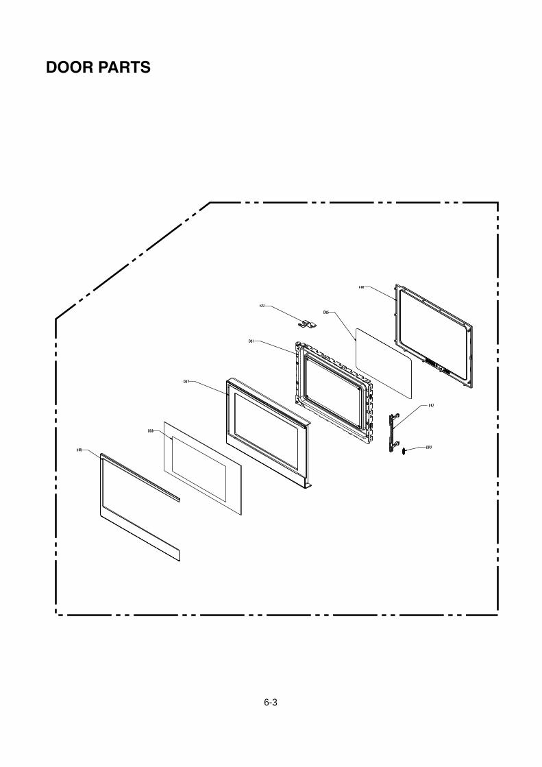
DOOR PARTS

6-4
PLATFORM EXPLODED VIEW

7-1
REPLACEMENT PARTS LISTNOTE:
1. When ordering replacement part(s), please use part number(s) shown in this part list.Do not use description of the part.
2. Important safety notice:Components identified by mark have special characteristics important for safety.When replacing any of these components, use only manufacture’s specified parts.
For Model: NN-SG636S CTH
PartName&Description
Pcs/SetRemark
s
A00 12270000004820 ASS'Y CAVITY 1
A01 12570000001036 SPLASH COVER 1
B01 12270000005139 BASE PLATE 1
B02 12170000000192 RUBBER FOOT 4
D46 12270000006167 ASS'Y HINGE *LOWER 1
C0017270000A71656+17170000A01312+160700
00A34185ASS'Y C/PANEL 1 component
C01 12170000014189 CONTROL PANEL 1 black
C02 12270000018297 DECO. C/PANEL 1 SUS
C05 16070000A34185 MEMBRANE DECO. 1 black
C07 12170000007208 DOOR OPEN BUTTON 1 black
C08 12970000000400 BUTTON SPRING 2
C13 12170000009459 DOOR OPEN LEVER 1
C26 17170000A01312 MEMBRANE SWITCHCIRCUIT 1
C38 12270000000604 DOOR OPEN BUTTONDECO. 1 SUS
C55 12270000018296 SHIELDER 1
C77 17170000009000 ASS'Y PCB 1
D00 12270000A73146+12570000A05517 ASS'Y DOOR 1 component
D01 12270000003835 ASS'Y DOOR FRAME 1
D02 12170000003870 LATCH 1
D03 12970000000365 LATCH SPRING 1
D22 12270000006147 ASS'Y HINGE *UPPER 1
D05 12170000009509 DOOR FILM 1
D06 12570000A05517 DOOR SCREEN 1
D07 12170000014188 DOOR PANEL 1 black
D08 12170000009546 DOOR GASKET 1
D09 12270000A47530 DOOR DECO. 1 SUS
Y30+Y32+Y31 17170000004576 ASS'Y SENSOR 1
W06 12170000000653 PLASTIC DAMPER 1
Safety Ref.No. Midea part No.
7-2
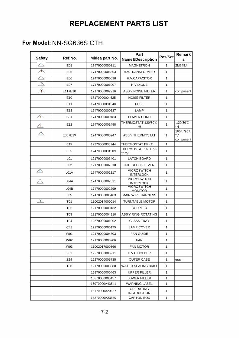
REPLACEMENT PARTS LIST
For Model: NN-SG636S CTHPart
Name&DescriptionPcs/Set
Remarks
E01 17470000000811 MAGNETRON 1 2M248J
E05 17470000005503 H.V.TRANSFORMER 1
E06 17470000000696 H.V.CAPACITOR 1
E07 17470000001007 H.V.DIODE 1
E11+E10 17170000002916 ASS'Y NOISE FILTER 1 component
E10 17170000004625 NOISE FILTER 1
E11 17470000001540 FUSE 1
E13 17470000000637 LAMP 1
B31 17470000000183 POWER CORD 1
E32 17470000001498 THERMOSTAT 120/80*H
1 120/80*H
E35+E19 17470000000247 ASS'Y THERMOSTAT 1160/95*Vcomponent
E19 12270000008244 THERMOSTAT BRKT. 1
E35 17470000001509 THERMOSTAT 160/95 *V
1
L01 12170000003401 LATCH BOARD 1
L02 12170000007318 INTERLOCK LEVER 1
L01A 17470000002317 MICROSWITCHINTERLOCK 1
L04A 17470000002311 MICROSWITCHINTERLOCK 1
L04B 17470000002299 MICROSWITCHMONITOR 1
L05 17470000005483 MAIN WIRE HARNESS 1
T01 11002014000014 TURNTABLE MOTOR 1
T02 12170000000432 COUPLER 1
T03 12170000004310 ASS'Y RING ROTATING 1
T04 12570000001002 GLASS TRAY 1
C43 12270000000175 LAMP COVER 1
W01 12170000004303 FAN GUIDE 1
W02 12170000000206 FAN 1
W03 11002017000366 FAN MOTOR 1
Z01 12270000006211 H.V.C HOLDER 1
Z24 12270000005735 OUTER CASE 1 gray
T36 12170000003988 WATER SEALING BRKT 1
16370000000463 UPPER FILLER 1
16370000000457 LOWER FILLER 1
16070000A43541 WARNING LABEL 1
16170000A29657 OPERATINGINSTRUCTION 1
16270000A23530 CARTON BOX 1
Safety Ref.No. Midea part No.

Safety Ref.No. Midea Part No.Part
Name&DescriptionPcs/Set Remarks
A00 12270000004820 ASS'Y CAVITY 1
A01 12570000001036 SPLASH COVER 1
B01 12270000005139 BASE PLATE 1
B02 12170000000192 RUBBER FOOT 4
D46 12270000006167 ASS'Y HINGE *LOWER 1
C0017270000A71662+16070000A34186+17170000A0
1313ASS'Y C/PANEL 1 component
C01 12170000014189 CONTROL PANEL 1 black
C02 12270000018297 DECO. C/PANEL 1 SUS
C05 16070000A34186 MEMBRANE DECO. 1 black
C07 12170000007208 DOOR OPEN BUTTON 1 black
C08 12970000000400 BUTTON SPRING 2
C13 12170000009459 DOOR OPEN LEVER 1
C26 17170000A01313 MEMBRANE SWITCHCIRCUIT 1
C38 12270000000604 DOOR OPEN BUTTONDECO. 1 SUS
C55 12270000018296 SHIELDER 1
C77 17170000009000 ASS'Y PCB 1
D00 12270000A73188+12570000A05518 ASS'Y DOOR 1 component
D01 12270000003835 ASS'Y DOOR FRAME 1
D02 12170000003870 LATCH 1
D03 12970000000365 LATCH SPRING 1
D22 12270000006147 ASS'Y HINGE *UPPER 1
D05 12170000009509 DOOR FILM 1
D06 12570000A05518 DOOR SCREEN 1
D07 12170000014188 DOOR PANEL 1 black
D08 12170000009546 DOOR GASKET 1
D09 12270000A47530 DOOR DECO. 1 SUS
Y30+Y32+Y31 17170000004576 ASS'Y SENSOR 1
W06 12170000000653 PLASTIC DAMPER 1
REPLACEMENT PARTS LISTNOTE:
1. When ordering replacement part(s), please use part number(s) shown in this part list.Do not use description of the part.
2. Important safety notice:Components identified by mark have special characteristics important for safety.When replacing any of these components, use only manufacture’s specified parts.
For Model: NN-SG656S CTH
7-3

Safety Ref.No. Midea Part No.Part
Name&DescriptionPcs/Set Remarks
E01 17470000000811 MAGNETRON 1 2M248J
E05 17470000005503 H.V.TRANSFORMER 1
E06 17470000000696 H.V.CAPACITOR 1
E07 17470000001007 H.V.DIODE 1
E11+E10 17170000002916 ASS'Y NOISE FILTER 1 component
E10 17170000004625 NOISE FILTER 1
E11 17470000001540 FUSE 1
E13 17470000000637 LAMP 1
B31 17470000000183 POWER CORD 1
E32 17470000001498 THERMOSTAT 120/80*H
1 120/80 *H
E35+E19 17470000000247 ASS'Y THERMOSTAT 1160/95*Vcomponent
E19 12270000008244 THERMOSTAT BRKT. 1
E35 17470000001509 THERMOSTAT 160/95 *V
1
L01 12170000003401 LATCH BOARD 1
L02 12170000007318 INTERLOCK LEVER 1
L01A 17470000002317 MICROSWITCHINTERLOCK 1
L04A 17470000002311 MICROSWITCHINTERLOCK 1
L04B 17470000002299 MICROSWITCHMONITOR 1
L05 17470000005483 MAIN WIRE HARNESS 1
T01 11002014000014 TURNTABLE MOTOR 1
T02 12170000000432 COUPLER 1
T03 12170000004310 ASS'Y RING ROTATING 1
T04 12570000001002 GLASS TRAY 1
C43 12270000000175 LAMP COVER 1
W01 12170000004303 FAN GUIDE 1
W02 12170000000206 FAN 1
W03 11002017000366 FAN MOTOR 1
Z01 12270000006211 H.V.C HOLDER 1
Z24 12270000005735 OUTER CASE 1 gray
T36 12170000003988 WATER SEALING BRKT 1
16370000000463 UPPER FILLER 1
16370000000457 LOWER FILLER 1
16070000A43541 WARNING LABEL 1
16170000A29657 OPERATINGINSTRUCTION 1
16270000A23531 CARTON BOX 1
REPLACEMENT PARTS LIST
For Model: NN-SG656S CTH

8-1
SCHEMATIC DIAGRAM OF P.C.B
ABCDD C B A
Pow
erB
oard
SEG1
SEG3SEG4
SEG6SEG7
SEG
8
COM
1/SW
ACO
M2
COM
3CO
M4
COM
5
ZERO
BUZZ
ER
HUM_OHUM_A
KEY_
IN_1
KEY_
SCAN
_1
INRUSHMICRO
DOORLAMP
SWE
SWB
SWC
XINXOUT
DSDADSCL
SEG5
SEG2
SWD
KEY_
SCAN
_7
GRILL
C14
104
E722
0UF/
16V
+5V
Res
et
Mod
elSw
itch
KEY_
SCAN
_2KE
Y_SC
AN_3
KEY_
SCAN
_4KE
Y_SC
AN_5
KEY_
SCAN
_6
KEY_
IN_2
KEY_IN_3KEY_IN_4
DSD
A
+5V
12
34
56
JP1
JP6
DSC
L
R20
10K
R19
10K
OC
D
+5V
1 2 3 4 5 6 7 8 9 10 11 12 13
LED1
LED
4047
5*8
GRE
EN
SEG
1SE
G2
SEG
3SE
G4
SEG
5SE
G6
SEG
7SE
G8
COM
1/SW
A
COM
2
COM
3
COM
4
COM
5
E C
B
Q13 S855
0
E C
B
Q12 S855
0
E C
B
Q11 S855
0
E C
B
Q10 S855
0
E C
B
Q9 S855
0
R77
4K7
R76
4K7
R75
4K7
R74
4K7
R73
4K7
R72
220R
R71
220R
R70
220R
R69
220R
R68
220R
R67
220R
R66
220R
R65
220R
LED
Dis
play
Key
Boa
rd
Hum
idity
Sens
or
12
34
RLY3
MIC
ROD4 1N
4148
12
34
RLY2
INRU
SHPT
C1PT
CD3 1N
4148
INRU
SH
MIC
RO
GRI
LL
D2 1N41
48
12
34
RLY
1G
RILL
R8 10K
+5V R7 10
K
D1 1N41
48
+5V
C3 104
DOO
RR1 2K
R2 3K3
1 2
GN
DCN
1
DO
OR
B
C E
Q4
KRC
105(
2.2K
,47K
)
B
C E
Q3
KRC
105(
2.2K
,47K
)
B
C E
Q2
KRC
105(
2.2K
,47K
)
R3 4K7
E3 10uF
/16V
R9 10K
C4 105
B
C E
Q5
KRC
105(
2.2K
,47K
)
LAM
P
E C
B
Q6
KRA
107(
10K
,47K
)
+12V
+5V
R10
2K
E C
B
Q1
8550
D12
1N41
48D5 1N
4148
1 2
3 4
RLY4
MO
TOR
Rel
ayX
OU
T
R26
1M
C1220
PF
C11 20
PF
OSC
14M
Hz
R27
1KX
IN
Osc
illat
or
MO
TOR
R24
1K2
R22
3K3
R21
10K
R23
1K
E C
B
Q8
S855
0
C9 104
C10
104
RESE
T
+5V
烧烤、非烧
烤选择电阻:
1)烧
烤型不装
R8,
R7和烧烤其它部
分元器件均安
装2)
非烧烤型只装
R8
RESE
T
D10
01N
4007
R109
10K
D10
31N
4007
ZERO
E104
220u
F,16
V
+5V
@25
0mA
RX1
22R,
2W
D10
11N
4007
MO
TOR
Z100
4.3V
+-2%
R101
100R
R104
1KE103
470u
F,25
V@
250m
A
R106
4K7
L101
2.2m
H,0
.1A
S 1BP3
FB4
D5
S7
S8
S2
IC10
0LN
K36
4
1 234
IC10
2
PC81
7
C100
102,
1KV
123 4
IC10
1
PC81
7
+12V
R103
20R
C105
103
E102
470u
F,25
V
R111
100K
N
R110
1K
L100
4.7u
H,0
.3A
R105
330R
E101
10uF
,250
V
C101
102,
1KV
D10
41N
4007
C102
104
D10
21N
4007
D10
6
UF4
002
L
D10
7
UF4
002
2
679
4
10
5V12V
IN1
83
T1EE16
线绕
电阻
R102
100K
E100
10uF
,250
V
135CN10
0
VH
5-3
+5V
RY 100K
C103
104
C104
104
MC9
6F64
32Q
P55/
Rese
t1
P40
2
P41
3
P42
4
P33/
COM
4/SE
G2
10
P32/
COM
5/SE
G3
11
P31/COM6/SEG4 12
P30/COM7/SEG5 13
P27/SEG6 14
P26/SEG7 15
P22/SEG11 19
P21/SEG12/AN15 20
P20/SEG13/AN14 21
P10/SEG14/AN13 22
P11/
SEG
15/A
N12
/EIN
T12
23P1
2/SE
G16
/AN
11/E
INT1
124
P13/
SEG
17/A
N10
/BU
Z25
P07/
SEG
22/A
N5/
EIN
T530
P06/
SEG
23/A
N4/
EIN
T431
P05/
SEG
24/A
N3/
EIN
T332
P04/
SEG
25/A
N2/
EIN
T233
P03/SEG26/AN1/EINT134 P02/AN0/EINT035 P01/DSCL36 P00/DSDA37 VDD38 VSS39 P50/XOUT40 P51/XIN41 P52/EINT842 P5343 P54/EINT1044 P43
5
P37/
COM
06
P36/
COM
17
P35/
COM
2/SE
G0
8
P34/
COM
3/SE
G1
9
P25/SEG8 16
P24/SEG9 17
P23/SEG10 18
P14/
SEG
18/A
N9
26P1
5/SE
G19
/AN
827
P16/
SEG
20/A
N7
28P1
7/SE
G21
/AN
629
IC1
MC9
6F64
32Q
R60
1KR5
9
1KR5
8
1KR5
7
1KR5
6
1KR5
5
1KR5
4
1KKE
Y_SC
AN_7
KEY_
SCAN
_6
KEY_
SCAN
_5
KEY_
SCAN
_4
KEY_
SCAN
_3
KEY_
SCAN
_2
KEY_
SCAN
_1
1 2 3 4 5 6 7 8 9 10 11 12
CN3
C20
103
C21
103
C19
103
C18
103
R53
1KR5
21K
R51
1KR5
01K
R64
47K
R63
47K
R62
47K
R61
47K
KEY_
IN_4
KEY_
IN_3
KEY_
IN_2
KEY_
IN_1
COM1/SWA
SWB
SWC
SWA
SWB
SWC
R34
2KR3
52K
R36
2K
SWD SWD
R37
2K
SWE SWE
R38
2K
BUZ1
BUZ
+12V R1
82K
BUZZ
ER
R17
100R B
C E
Q7 KRC
107(
10K
,47K
)
Buz
zer
C25
103
C26
103
C24
103
C23
103
C29
103
C28
103
C27
103
美的版
按键模块:不
装C2
3~C2
9电容
松下版
按键模块:不
装R5
4~R5
7电阻
,
松下
1.3c
ft薄膜插座为
8 pin
.
E(G
)MLA
AM
R-S1
-K/E
MLA
ALL
-S1-
K
V1.
1
N
R205
150K
8
L200
2.2M
H
EC20
1
0.47
uF/5
0VVC
CEC
204
1uF/
16V
R212
470
R210
10K/
1%
2R2
072K
/1%
C204
104/
50V
R203
1M
6
EC20
347
uF/1
6V
15
R201
4K7
R208
2K/1
%
R213
56K
R204
1M
4
R211
10K
C200
47nF
R206
680K
HT_A
DR2
09
43k/
1%
C203
15P
EC20
22.
2uF/
50V
D200
1N41
48
3
7
VCC
C201
471
HT_C
ON
EC20
01u
F/50
V
HT_A
D
HT_CON
123456
CN20
0
CN6
L201
2.2M
H
GND
OU
T1
IN-
2
IN+
3
Vcc- 4Vcc+8
U200
A
LM35
8
R200
4K7
C202
104
OU
T7
IN-
6
IN+
5U2
00B LM
358
R202
1M
AD
1
GN
D2
VCC
3
CON
4
S15
S26
M1
HU
M-S
EN-Y
13
CN2
HU
M_A
GN
D+5
VH
UM
_O