model name : h27 - optomaeasp.optomausa.com/asp/upload/service manuals/h27 service manual...h27....
TRANSCRIPT

Model Name : H27
�����������
etaD noisreVesiveR noitpircseD
22/3/5002 0.1V eussIlaitinI
Copyright March, 2005 . All Rights Reserved
Document #80J-G04-01A . P/N: 36.80J02.001
Prepared by SI :
________________________________________
Prepared by TSE :
________________________________________
Checked by :
________________________________________
Approved by :
________________________________________

H27i
Preface������������������ ����������������������� ����������� ������!������"�#�������� ���$�������%���&
����'����(������ �)�*+�,�-�*)�+.,�����������������������/���!����0���$� �� ���������$�0��� ��� ���1
����$����������������������/� ���� �������������������� ��
2��� ��������3������� ���������4� 5���������������3����!������ ����!�� ����$!����0���������� �
3���������� �����'���-�� ��!��� ��������3������� ������������/� �������!���$$��������
�������������$����� ��� ������� �������3�����/������� ����� �0� 5���� ������ �������� ��0� 5���
���� �����0����$��������������� � ����������������� ����!�������������� ����-������������������� �������
���0����������
������
������$���������$�� ������������������0�� ����� ������3���������������� �����!��0��4���� ������
�� ��������� �����������3��0���� �������� ����$������� ������
6��!����������&���� �
��7������7����/�
�����.�������8��
�� ������9�)�:1��*1�8�

Table of ContentsChapter 1 Introduction 1-1
Product Highlights 1-1
Computer Compatibility (Analog and DVI) 1-4
Chapter 2 Disassembly of Procedure 2-1Removing Lamp Module 2-1
Removing Rear Cover, Keypad Board, Top Cover and Main Board 2-2
Removing 70x20 AXIAL Fan Module, Lamp Driver Module,
Interrupt Switch and LVPS Module 2-4
Removing Front Cover Insert, Front Cover, IR Receiver Board
and Zoom Ring 2-6
Removing Color Wheel Module and Engine Module 2-8
Disassemble Engine Module 2-9
Removing 50x20 Blower Fan Module, Elevator Module
and Thermal Sensor Board 2-10
Chapter 3 Troubleshooting 3-1Equipment Needed 3-1
Main Procedure 3-2
Chapter 4 Function Test and Alignment Procedure 4-1Product 4-1
Test Equipment 4-1
Test Condition 4-1
Test Display Modes and Pattern 4-2
Inspection Procedure 4-7
Chapter 5 Firmware Upgrade Procedure 5-1Equipment Needed 5-1
Hardware Setup Procedure 5-1
Firmware Upgrade Procedure 5-2
H27

Chapter 6 DDC Key-in Procedure 6-1Equipment Needed 6-1
Setup Procedure 6-2
DDC Key-in Procedure 6-3
Appendix A 7-1
Exploded Overview 7-1
Appendix B 7-15Serial Number System Definition 7-15
Appendix C 7-16
Board S/N Coding 7-16
Appendix D 7-17
DLP Composer Lite Setup Procedure 7-17
Appendix E 7-22
The Comparision of EDID Fixture 7-22
Reader’s Response 7-23
H27iii

H271-1
Chapter 1
Introduction
1-1 Product Highlights
- Target is to create the highest quality entry level home theatre projector in the market
- TI DMD, 0.5” 480P DDR SXGA Digital Mirror Device
- Uses Single 16:9 854 x 480 DMD
- Uses 2x six segment color wheel RGB
- High end scaler DDP2000 with 3:2\2:2 Pull Down
- Lightweight ID for a total weight 5.5 lb.
- SCART RGB support via an adaptor
- 35 +/- 2 dBA in normal mode
- On-Screen menu with 7 languages.
- Four types of projection method. (Front desktop, Front Ceiling, Rear desktop, Rear Ceiling)
- Four types of display mode. (Normal, Game TV, Movie or User for selections). *Notice
* Notice :
All modes except “Normal Mode” are fixed values. Only “ Normal Mode” can be
adjusted for user’s preference.
- Cooling System
a. Advanced air flow
b. Two fans with low system acoustic noise level
c. Temperature control circuits with adaptive voltage control fan speed.
- Tilt angle : 7 degrees with elevator mechanism
- IR receivers : Front and back of projector
- Power supply : Input 100-240V, 50/60Hz
- Power Consumption : 265W+-10% Full Power
H271-2
- Terminals :
a. One 29-pin DVI-I connector for Digital signal with HDCP input.
b. One D-Sub 15-pin female connector for analog RGB / HDTV / component video / SCART
RGBSync input.
c. One Mini DIN 4-pin for S-Video Input
d. One RCA Jack for Composite Video Input
e. Three RCA Jacks for component video / HDTV input
f. One Mini DIN 3-pin for RS232
- Input signal spec
a. PC Signal
b. Hsync Frequency 31.5 ~ 100 kHz
c. Vsync Frequency 56 ~ 85 Hz
d. Video Signal RGB (PC)
e. Analog RGB 0.7Vp-p, 75 ohm
f. Analog RGB 1Vp-p, 75 ohm, Sync. signal
g. Separate TTL H, V Sync.
h. Composite TTL Sync.
i. Video
j. Composite video 1Vp-p,75 ohm
k. S-video Luminance 0.714Vp-p,75 ohm
l. Chrominance 0.286Vp-p,75 ohm
- Video compatibility :
NTSC : M (3.58MHz), 4.43 MHz, 480i
PAL : B, D, G, H, I, M, N; 576i
SECAM : B, D, G, K, K1, L
HDTV : 480p, 576p, 720p, 1080i
- WVGA / Compression : by using “DDP2000” Chips to compress SVGA/XGA/SXGA image into
WVGA display.
- Keystone correction : +/ -16 degree
- Brightness :
Specification : 800 lumens ; 520 lumens (minimum)
- Contrast ratio :
Specification : 2300:1 or higher full on/full off ; 1300:1 full on/full off (minimum)

H271-3
- Uniformity :
Specification : 85% (Japan standard)
- Displayable colours : 16.7 million colours 256 shades of gray
- Color temperature : 7500° K (Video) Adjustable from 6500° K to 9500° K
- Lamp type : 200W lamp with ECO mode supported.
- Lamp life : 2000 hours Brite mode
3000 hours ECO mode
1500 hours to 50% survival typical
- Projection lens : F/ 2.6~2.8, f = 22.34 ~ 26.8mm. Zoom Lens
- Projection screen size : 30.1” to 241.6” (Diagonal for 16:9)
- Projection distance : 1.5M ~ 10M
- Throw ratio : 1.87~2.25:1 distance/width
- Operational noise :
Specification : 28dB (Normal mode),32 dB (Brite mode)
- Temperatures :
a. Operating: 5-35°C, 80% humidity (Max.)
b. Storage: -20 - 60°C, 80% humidity (Max.)
- Altitude :
a. Operating 5-35°C @ 0 - 2,500 ft
5-30°C @ 2,500 - 5,000 ft
5-25°C @ 5,000 - 10,000 ft
b. Storage 40,000 ft (Max.)
- MTBF : Operating more than 12,000 hours ( 90% Confidence Level )

H271-4
1-2 Computer Compatibility (Analog and DVI)
ytilibitapmoC noituloseR ]zH[cnyS-V ]zHK[cnyS-H
AGV 053x046 07 5.13
053x046 58 9.73
004x046 58 9.73
084x046 06 5.13
084x046 27 9.73
084x046 57 5.73
084x046 58 3.34
004x027 07 5.13
004x027 58 9.73
AGVW 084x458 06 2.23
AGVS 006x008 65 2.53
006x008 06 9.73
006x008 27 1.84
006x008 57 9.64
006x008 58 7.35
AGX 867x4201 06 4.84
867x4201 07 5.65
867x4201 57 0.06
867x4201 58 7.86
AGXS 468x2511 07 8.36
4201x0821 06 89.36
"61CAM 426x238 55.47 527.94
"91CAM 867x4201 57 42.06
CAM 078x2511 60.57 86.86
4GCAM 084x046 06 53.13
VDcaMi 867x4201 57 06
VDcaMi 078x2511 57 94.86

H272-1
Chapter 2
Disassembly Procedure
The Front Side The Rear Side
Equipment Needed
Screw Bit(+) : 107
Hex Sleeves 5mm
Screw Bit(+) : 101
Hex Sleeves 8mm
Appearance

H272-2
1. Unscrew 4 screws and 4 hex screws to remove Rear Cover.
Rear Cover
2-2 Removing Rear Cover, Keypad Board, Top Coverand Main Board
Hex screws
2-1 Removing Lamp Module1. Turn over the unit.
Loosen 2 screws to remove Lamp Cover.
Loosen 2 screws to pull out Lamp Module.
Lamp Module
H272-3
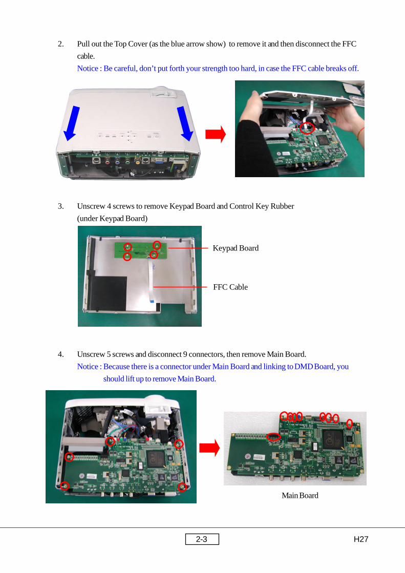
3. Unscrew 4 screws to remove Keypad Board and Control Key Rubber
(under Keypad Board)
2. Pull out the Top Cover (as the blue arrow show) to remove it and then disconnect the FFC
cable.
Notice : Be careful, don’t put forth your strength too hard, in case the FFC cable breaks off.
Keypad Board
FFC Cable
4. Unscrew 5 screws and disconnect 9 connectors, then remove Main Board.
Notice : Because there is a connector under Main Board and linking to DMD Board, you
should lift up to remove Main Board.
Main Board

H272-4
1. Unscrew 2 screws to remove 70x20 AXIAL Fan Module.
2. Unscrew 4 screws and 2 hex spacers and disconnect the connector to remove Lamp Driver
Module.
3. Unscrew 2 screws to remove Interrupt Switch.
2-3 Removing 70x20 AXIAL Fan Module, Lamp DriverModule, Interrupt Switch and LVPS Module
70x20 AXIAL Fan Module
Lamp Driver Modulehex spacers connector

H272-5
4. Unscrew 7 screws (one of 7 screws is used by Grounding) to remove LVPS Module.
used by Grounding
Interrupt
SwitchLVPS Plate
LVPS Module

H272-6
2. Unscrew one screw, then loosen 4 tenons inside of the Front Cover.
Finally remove Front Cover.
Notice : Lift up the four plastic plates and you can loosen the tenons as well as the Front Cover
Module.
2-4 Removing Front Cover Insert, Front Cover,IR Receiver Board and Zoom Ring
1. Remove Front Cover Insert.
Notice : Press two sides of the Front Cover Insert to lift it up.
Zoom Ring

H272-7
4. Take off the Mylar to remove IR Receiver Board.
IR Receiver Board
Front Cover
Zoom Ring
Front Cover Insert
3. Remove Zoom Ring.

H272-8
1. Unscrew one screw to remove Color Wheel Module from Engine Module.
2. Loosen one screw from Engine Base, then unscrew 6 screws to remove Engine Module.
2-5 Removing Color Wheel Module andEngine Module
Color Wheel Module
Notice : Please screw well (the two tenons
should be stick out) when you
assemble Color Wheel Module.
Lens Clamp/Stopper
MB Bracket
Color Wheel
Module
Two tenons

H272-9
1. Unscrew 4 screws to remove HeatSink from Engine Module.
2. Unscrew 4 screws to remove Formatter Board and DMD Chip from Engine Module.
3. Unscrew 2 screws to remove Light Cut.
Formatter Board
Heat Sink
DMD Chip
2-6 Disassemble Engine Module
DMD Thermal Pad
DMD Insulator Mylar
DMD Heatsink Baker Plate
DMD Heatsink
DMD Heatsink Spring Plate
SUB ASSY Engine Module
Light Cut
Sponges
Notice : Don’t forget to paste the sponges when you assemble the SUB ASSY Engine Module.

H272-10
1. Unscrew 3 screws to remove 50x20 Blower Fan Module.
2. Unscrew one screw to remove Thermal Sensor Board.
2-7 Removing 50x20 Blower Fan Module, ElevatorModule and Thermal Sensor Board
50x20 Blower Fan Module
Thermal Sensor Board

H272-11
3. Unscrew 9 screws to remove Bottom Base and Elevator Module.
4. Turn over the Bottom Base and unscrew two screws to remove Elevator Foot.

H273-1
3-1 Equipment Needed
Chapter 3
Troubleshooting
- PC or pattern generator
- DVD player (Video, S-Video, Audio, HDCP/HDMI)
- Quantum Data 802B or CHROMA 2327
3-2 Main Procedure
3-2.1 No Power- Ensure that the power cord and AC power outlet are securely connected.
- Check Lamp Cover and Interrupt Switch
- Ensure that all connectors are securely connected and haven’t broken.
- Check LVPS
- Check Lamp Driver
- Check Main Board
3-2.2 Auto Shutdown- Check LED indicator *Notice
a. If Lamp LED lit, please check Lamp Module
b. If Temp LED lit, please check Thermal Sensor Board
c. If Temp LED blinks, please check Fan Module
d. If Power LED off, please check LVPS
- Check Main Board
- Check Lamp Driver
3-2.3 No Image- Ensure that the signal cables and source are work as well. (If you connect multiple
sources at the same time, use the “Source” button on the control panel to switch.)
- Ensure that all connectors are securely connected and haven’t broken.
- Check Main Board
- Check DMD Board
- Check Color Wheel
H273-2
- Check DMD Chip
- Check Engine Module
3-2.4 No Light on- Ensure that all connectors are securely connected and haven’t broken.
- Check Lamp Module
- Check LVPS
- Check Lamp Driver
- Check Main Board
3-2.5 Mechanical Noise- Check Color Wheel
- Check Fan Module
- Check LVPS
- Check Lamp Driver
- Check Engine Module
3-2.6 Line Bar/Line Defect- Sometimes it’s because of DMD chip and DMD board did not assemble properly
- Check DMD Board
- Check DMD Chip
- Check Main Board
3-2.7 Image Flicker- Do “Factory Reset” of the engineering mode.
- Ensure that the signal cables and source are work as well.
- Check Lamp Module
- Check Color Wheel
- Check DMD Board
- Check Main Board
3-2.8 Color Abnormal- Check “Color Setting” of the engineering mode.
(including ADC calibration and Color Wheel index)
- Check Main Board
- Check DMD Board
- Check Color Wheel

H273-3
3-2.9 Poor Uniformity/Shadow- Ensure the projection screen without dirty
- Ensure the projection lens is clean
- Ensure the Brightness is within spec.
a. Replace the Lamp if the Brightness is less than spec.
- Check Engine Module
3-2.10 Dead Pixel/Dust (Out of spec.)- Ensure the projection screen without dirty
- Ensure the projection lens is clean
- Clean DMD Chip and Engine Module
- Check DMD Chip
- Check Engine Module
3-2.11 Screen Size Abnormal- Do “Factory Reset” of the engineering mode.
- Adjust “Aspect Ratio”
- Check Main Board
3-2.12 Garbage Image- Ensure that the signal cables and source are work as well.
- Check Main Board
- Check DMD Board
3-2.13 Remote Mouse Abnormal- Check PC/Laptop (Hardware setting)
- Check battery
- Check Remote Controller
- Check IR Receiver Board
- Check Main Board
3-2.14 OSD Problem- Remote Controller and Control Panel Both Failed
a. Check Main Board
- Remote Controller Failed
a. Check battery
b. Check Remote Controller

H273-4
c. Check IR Receiver Board
d. Check Main Board
- Control Panel Failed
a. Check Cable FFC
b. Check Keypad Board
c. Check Main Board
- Function Abnormal
a. Do “Factory Reset” of the engineering mode
b. Do Firmware Upgrade
c. Check Main Board
d. Check DMD Board
3-2.15 Firmware/EDID Upgrade Failed- Check hardware setting
Firmware hardware setting (please refer to pages 5-1 and 5-2)
EDID hardware setting (please refer to pages 6-1 and 6-2)
- Check PC/Laptop setting
- Check PC/Laptop OS system
- Check program
- Re-boot PC/Laptop
- Check Main Board
3-2.16 Other Input Signal Problem- Video/S-Video No Image, Image Noise or Line Defect (DVI input OK)
a. Check Main Board
- DVI No Image (Video/S-Video input OK)
a. Check Main Board
- DVI Image Noise/Ripple (Video/S-Video input OK)
a. Adjust “Tracking” function
b. Change resolution/refresh rate
c. Check Main Board
- DVI Line Defect (Video/S-Video input OK)
a. Check Main Board
- DVI input with poor quality of text
a. Check resolution
b. Check Main Board

H273-5
* Notice :
L E D S ta tu s M e a n in g O p e ra tio n
Te m p + L a m p P ro je c to r is c he c k i f ne e d to A U TO
B U R N - IN P o w e r c o rd p lug g e d
Te m p + L a m p
(L a s ting o ve r 4 s e c )
P ro je c to r is in A U T O B U R N - IN d e la y
p ro c e d ure , i t ta k e s 9 0 ~ 5 9 0 s e c
ra nd o m ly
P o w e r c o rd p lug g e d
P o w e r
(B link ) S ta nd b y m o d e P o w e r c o rd p lug g e d
P o w e r B U R N - IN d e la y tim e s up a nd
c o nti n ue B U R N - IN p ro c e d ure P o w e r c o rd p lug g e d
P o w e r N o rm a l o p e ra tio n P o w e r b ut to n
p re s s e d
Te m p P ro je c to r o ve r he a te d
Te m p
(B link ) F a n lo c k
L a m p L a m p fa i l
P o w e r
C o o ling s ta g e 1
(N o t in te rr up tib le )
(F a n b lo w s )
N o rm a l tu r n o f f
P o w e r
(B link )
C o o ling s ta g e 2
(C a n a c c e p t P O W E R b u tto n )
(F a n b lo w s la s ting a b o u t 6 0 s e c )
N o rm a l tu r n o f f
P o w e r + Te m p + L a m p
B U R N - IN d e la y s ta g e 1
(N o t in te rr up tib le )
(F a n b lo w s )
B U R N - IN
Te m p / L a m p
(b link in te rla c e d )
B U R N - IN d e la y s ta g e 2
(C a n a c c e p t P O W E R b u tto n )
(F a n b lo w s la s ting a b o u t 7 0 s e c )
B U R N - IN

H274-1
4-1 Product- H27
4-2 Test Equipment- IBM PC with WVGA resolution (Color Video Signal & Pattern Generator)
- DVD player with component video (Y, Pb, Pr) and Multi-system (NTSC/PAL/
SECAM)
- HDTV Tuner or Source (480i/p, 576i/p, 720p, 1080i)
- Minolta CL-100
- CHROMA 2316, Quantum Data 802B or CHROMA2327
4-3 Test Condition
Chapter 4
Function Test and AlignmentProcedure
- Circumstance Brightness : Dark room less than 2.5 lux.
- Inspection Distance : 1.5m~3m for functional inspection
- Screen Size : 60 inches diagonal (wide)
- After repairing each H27, the unit should be burn-in for at least 4 hours.
Notice : Set H27 in Burn-in Mode
Press “Power”, “ ”, “ ”, “Menu” to enter the engineering mode.
Choose “Burn in test”, and then set “Lamp on (min.)” to 240,
“Lamp off (min.)” >0 and “Set burn in cycle” to 1.

H274-2
4-4 Test Display Modes & Pattern
4-4.1 Compatible Modes (Analog and DVI)
ytilibitapmoC noituloseR ]zH[cnyS-V ]zHK[cnyS-H
AGV 053x046 07 5.13
053x046 58 9.73
004x046 58 9.73
084x046 06 5.13
084x046 27 9.73
084x046 57 5.73
084x046 58 3.34
004x027 07 5.13
004x027 58 9.73
AGVW 084x458 06 2.23
AGVS 006x008 65 2.53
006x008 06 9.73
006x008 27 1.84
006x008 57 9.64
006x008 58 7.35
AGX 867x4201 06 4.84
867x4201 07 5.65
867x4201 57 0.06
867x4201 58 7.86
AGXS 468x2511 07 8.36
4201x0821 06 89.36
"61CAM 426x238 55.47 527.94
"91CAM 867x4201 57 42.06
CAM 078x2511 60.57 86.86
4GCAM 084x046 06 53.13
VDcaMi 867x4201 57 06
VDcaMi 078x2511 57 94.86

H274-3
4-4.2 Function Test Display Pattern
metI tnetnoCtseT nrettaP noitacificepS krameR
1&ycneuqerF
gnikcarTerioMeniLeniF
ybesionyvawlausivetanimilEgnikcarTroycneuqerF,cnysR
.noitceles1erugiF
2 ssenthgirB/tsartnoC/elacSyarG61elacsWBGR46
ebdluohslevelyarGroloctuohtiwdnaelbahsiugnitsid
.lamronba
erugiF3,2
3etihWdnaB,G,RecnamrofreProloC
dnaB,G,RroloCetihW
ebdluohsrolocB,G,RhcaElamronbaroloctuohtiwlamron
.eussi
Fi erug4 7~
4 ytimrofinUneercS etihWlluFhtiwtnailpmocebdluohS
)muminiM(.%56Fi erug 7
5
thgirB(lexiPdaeD)lexip
kcalBlluF lexipthgirbynatpeccatonnaC 8erugiF
kraD(lexiPdaeD)lexip
etihWlluFdluohslexipdaedfosrebmunehT
.lexip6ottnuomarorellamseb7erugiF
6 )thgirB(hsimelByarG/kcalBlluF
03
ebtonnachsimelbthgirbehThtiwraeppamelborpehtfitpecca
.nrettap03yraG
,8erugiF9
7 )kraD(hsimelBeulB/etihwlluF
06
tpeccaebtonnachsimelbkradehT06eulBhtiwraeppamelborpehtfi
.nrettap
erugiF01,7
8 sucoF nrettaPtxeTebdluohsrenrocehtnitxetehT.gnirsucofehttsujdaretfaraelc
erugiF11
9 yradnuoB emarFyradnuoBoedivfonoitisop.treVdnA.zroH
ehtebotelbatsujdaebdluohs.emarfneercs
erugiF21
01 kaeLthgiL 01yarGsiegakaelehttpeccat'nactinuehT
nrettap01yarGnahtrethgirberugiF
31

H274-4
Figure 7. Full White Figure 8. Full Black
Figure 1. Fine Line Moire Figure 2. 16 Gray Scale
Figure 3. 64 RGBW Scale Figure 4. Red Pattern
Figure 5. Green Pattern Figure 6. Blue Pattern

H274-5
Figure 9. Gary 30 Pattern Figure 10. Blue 60 Pattern
Figure 11. Text Pattern Figure 12. Boundary Frame
Figure 13. Gary 10 Pattern
H274-6
4-5 Inspection Procedure
- Factory Reset
Please press “Power”, “ ”, “ ”, “Menu” on the projector control panel to enter the
engineering mode, and then choose “Factory Reset” then choose “YES” and press enter to see
if it works.
This action will allow you to erase all end-user’s settings and restore the original setting.
- Firmware Version
Test Signal : None
Test Pattern : Service Mode
* Check and see if the firmware version is suited to the projector.
- Frequency and Tracking
Test Signal : 854x480@60Hz
Test Pattern : Line Moire Pattern
* Check and see if image sharpness and focus is well performed.
* If not, readjust by following steps.
(1) Select “Frequency” function to adjust the total pixel number of pixel clock in one
line period.
(2) Then select “Tracking” function and use right or left arrow key to adjust the value
to minimize video flicker.
- Boundary
Test Signal : 854x480@60Hz
Test Pattern : Boundary Frame
* Adjust Resync or Frequency/Tracking/H. Position/V. Position to the inner of the screen.
- Focus
Test Signal : 854x480@60Hz
Test Pattern : Text Pattern
* Adjust the center clearly, meanwhile, one slightly vague corner in the image is allowed
- HDTV
Equipment : Quantum Data 802B or CHROMA 2327
Test Signal : 576P, 720P, 1080i
Test Pattern : Master
If the test result was discoloration or flickering, please adjust Video Calibration first.
Notice : (1) Please ignore the image flickering under 480P signal.
(2) Video Calibration :
Test Signal : 480P
Test Pattern : SMPTE Bar
- Enter the engineering mode and choose “Color setting”
- Choose “Reset offset”
H274-7
- Connect the signal
- Choose “Video Calibration” function
- Color Performance and Contrast
Test Signal : 854x480@60Hz
Test Pattern : 64 RGBW scale Pattern and Gray 16 Pattern
* Please check and ensure if each color is normal and distinguishable
* If not, please return the unit to repair area.
- Screen Uniformity
Test Signal : 854x480@60Hz
Test Pattern : Full White Pattern
* Please check and ensure the unit is under the spec. (Pixel number should be smaller or
amount to 6 pixels.)
* Please check and see if it’s in normal condition.
* If not, please return the unit to repair area.
- Dead Pixel (Bright/Dark pixel)
Test Signal : 854x480@60Hz
Test Pattern : Full Black Pattern and Full White Pattern
* Please check and see if there are dead pixels on DMD chip
* The total numbers and distance of dead pixels should be complaint with the spec.
Notice : (1) Bright Pixel :
Test Pattern : Full Black Pattern
- Please check and ensure that the unit cannot accept any bright pixel.
- If not, please return the unit to repair area.
(2) Dark Pixel :
Test Pattern : Full White Pattern
- Please check and ensure that the pixel number should be smaller or
amount to 6 pixels
- If not, please return the unit to repair area.
- Light Leak
Test Signal : 854x480@60Hz
Test Pattern : Gray 10 Pattern
* Please check and see if the light leaks*Notice
* The unit cannot accept the leakage is brighter than Gary 10 pattern
Notice : light leak on reflective edge, eyecatcher, bond wires and exposed metal.
- ECO Mode
Test Signal : 854x480@60Hz
Test Pattern : Gray Scale Pattern
* Press “Menu” and choose “Brite” function
* When choose “On”, the screen will become darkness.
* When choose “Off”, the screen will resume normally.

H274-8
- Remote Controller
Test Signal : Any
Test Pattern : Any
* Cover Front IR Receiver up first and then test the remote controller.
* Cover Rear IR Receiver up first and then test the remote controller.
- Projection Mode
Test Signal : Any
Test Pattern : Any
* Test all projection modes to ensure the displays are normal or not.
- Aspect Ratio (4:3/16:9/1:1/Letterbox)
Test Signal : Any
Test Pattern : Any
* Please check and see if it’s in normal condition.
* If not, please return the unit to repair area.
- Check for Secondary Display Modes
Test Signal :
* 640x350 (70Hz, 31.5KHz/85Hz, 37.9KHz)
* 640x400 (85Hz, 37.9KHz)
* 640x480 (60Hz, 31.5KHz/72Hz, 37.9KHz/75Hz, 37.5KHz/85Hz, 43.3KHz)
* 720x400 (70Hz, 31.5KHz/85Hz, 37.9KHz)
* 800x600 (56Hz, 35.2KHz/60Hz, 37.9KHz/72Hz, 48.1KHz/75Hz, 46.9KHz/85Hz,
53.7KHz)
* 1024x768 (60Hz, 48.4KHz/70Hz, 56.5KHz/75Hz, 60.0KHz/85Hz, 68.7KHz)
* 1152x864 (70Hz, 63.8KHz)
* 1280x1024 (60Hz, 63.98KHz)
* 832x624 (74.55Hz, 49.725KHz)
* 1024x768 (75Hz, 60.24KHz)
* 1152x870 (75.06Hz, 68.68KHz)
* 640x480 (60Hz, 31.35KHz)
* 1024x768 (75Hz, 60KHz)
* 1152x870 (75Hz, 68.49KHz)
Normally when the primary mode 854x480@60Hz is well adjusted and complaint with the
specification, then the secondary display modes will be great possibility to be complaint with
the specification. But we still have to check with general test pattern to make sure every
secondary modes is complaint with specification.
H274-9
- Factory Reset
After final QC step, we have to erase all saved change again and restore the factory defaults.
Please press “Power”, “ ”, “ ”, “Menu” on the projector control panel to enter the
engineering mode, and then choose “Factory Reset” then choose “YES” and press enter to see
if it works.
This action will allow you to erase all end-user’s settings and restore the original setting.

H275-1
Chapter 5
Firmware Upgrade Procedure
5-1 Equipment Needed
5-2 Hardware Setup Procedure
Software :- DLP Composer Lite
- H27.IMG
Hardware :- H27 Projector
- PC or Laptop
- Cable One Mini DIN 3-pin for RS232
- Power Cord
1. Connecting the RS232 Cable (One Mini DIN 3-pin) between PC/Laptop and H27
projector.
Notice : Do not connect the H27 Power Cord in this procedure.
RS232 Cable

H275-2
5-3 Firmware Upgrade Procedure1. Keep pressing "Menu" button and then plug in the H27 power cord until "LAMP",
"TEMP" and "POWER" LED turn into the light.
Notice : "LAMP" and "TEMP" LED turn into light first at the same time, and then
"POWER" LED turn into the light. ( Firmware Upgrade Mode)
3. Click "Edit" and then "Preferences...".
2. Execute the "DLP Composer Lite" program.

H275-3
4. Check the path that you installed "DLP Composer Lite" is correct or not.
If the path is wrong, please click "Browse" to select the right path.
5. Click "Communications"
Choose "Projector Interface" as "Serial Port DDP2000"
Select "COM1" port and then click "Configure"
1
2
3 4
H275-4
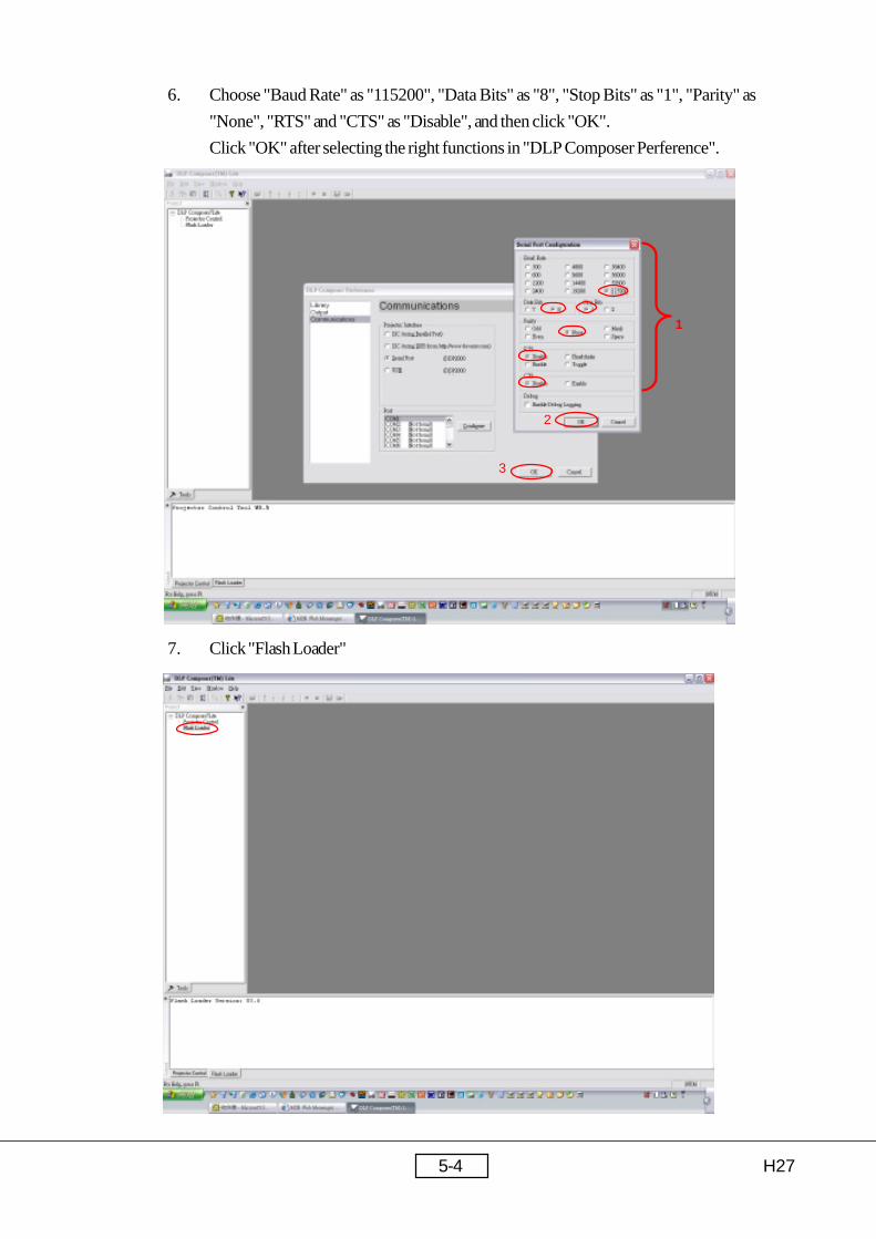
6. Choose "Baud Rate" as "115200", "Data Bits" as "8", "Stop Bits" as "1", "Parity" as
"None", "RTS" and "CTS" as "Disable", and then click "OK".
Click "OK" after selecting the right functions in "DLP Composer Perference".
7. Click "Flash Loader"
1
2
3
H275-5
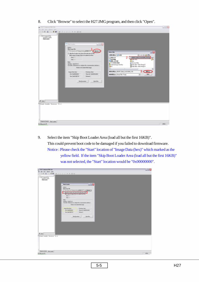
8. Click "Browse" to select the H27.IMG program, and then click "Open".
9. Select the item "Skip Boot Loader Area (load all but the first 16KB)".
This could prevent boot code to be damaged if you failed to download firmware.
Notice : Please check the "Start" location of "Image Data (hex)" which marked as the
yellow field. If the item "Skip Boot Loader Area (load all but the first 16KB)"
was not selected, the "Start" location would be "0x00000000".
1
2
3

H275-6
10. Click "Reset Bus" and you will see the status change to "Bus Reset"
11. Click "Start Download" and then click "Yes" to continue.
1
2

H275-7
12. You will see the status is earsing elash ROM at first, and then downloading the new
firmware. *Notice
13. Download complete.
H275-8
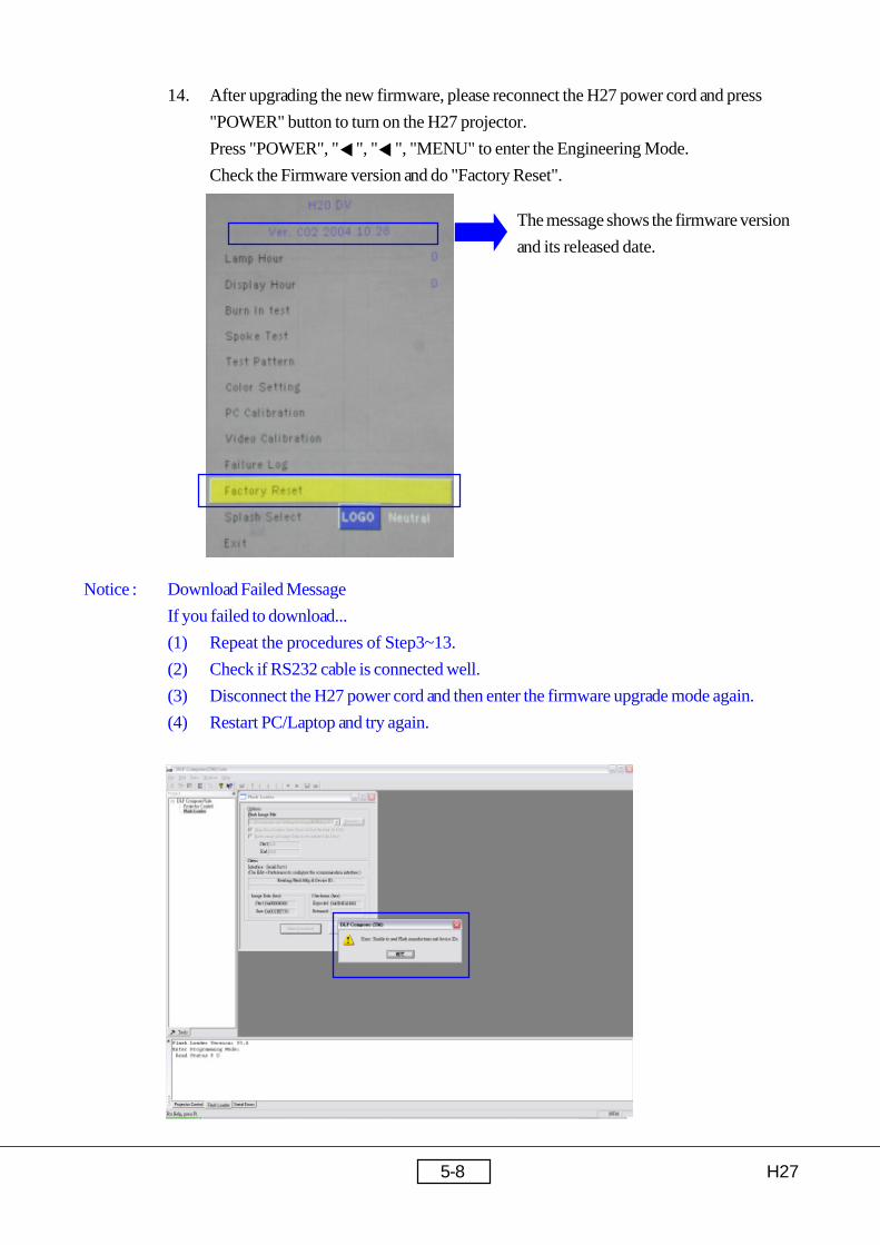
Notice : Download Failed Message
If you failed to download...
(1) Repeat the procedures of Step3~13.
(2) Check if RS232 cable is connected well.
(3) Disconnect the H27 power cord and then enter the firmware upgrade mode again.
(4) Restart PC/Laptop and try again.
14. After upgrading the new firmware, please reconnect the H27 power cord and press
"POWER" button to turn on the H27 projector.
Press "POWER", " ", " ", "MENU" to enter the Engineering Mode.
Check the Firmware version and do "Factory Reset".
The message shows the firmware version
and its released date.

H276-1
Chapter 6
DDC Key-in Procedure
6-1 Equipment Needed
- PC or Laptop
- EDID Fixture
- DVI to DVI Cable
- Power Adapter
- RS-232 Cable (Female to Female)
- VGA Cable
- Power Cord
- DDC Driver
- H27 Unit
EDID Fixture
P/N : 80.00001.001
DVI to DVI Cable
P/N : 42.56108.201
RS-232 Cable (F-F)
P/N : 42.86603.001 VGA Cable
P/N : 42.53001.051
Power Adapter
P/N : 47.53402.004

H276-2
6-2 Setup Procedure
Step1. Connect Power Adapter with the fixture.
Step2. Connect P1 of the fixture with COM1 of PC/Laptop by RS232 cable.
Step3. Connect P2 or P4 of the fixture with VGA in port of H27 cable.
Step4. Connect P3 of the fixture with DVI port of DVI-DVI cable.
Step5. Plug Power Adapter to the fixture and connect the H27 Power Cord.
*Notice : Confirm JP3 is “Close” status (EDID Mode).
P3 P2 P4
Power Adapter P1
COM1
VGA in port
DVI port
marked as “Generic”
JP3

H276-3
6-3 DDC Key-in Procedure
Step 1. Execute “EDID” program.
Step 2. Check the Com port is “COM1”, then click the “Model” item and choose the
source file “DREAMY_H27_EDID2_110m” and then open it.
1
2
H276-4
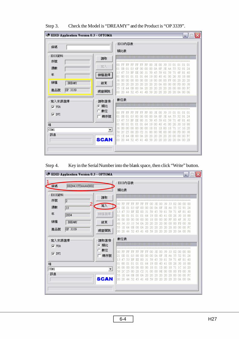
Step 3. Check the Model is “DREAMY” and the Product is “OP 3339”.
Step 4. Key in the Serial Number into the blank space, then click “Write” button.
1
2

H276-5
Step 5. “Please connect to VGA” message is shown on the screen, then click “OK”
button.
Notice : “RUN” message will appear on the screen.
Step 6. “Please connect to DVI” message is shown on the screen, then click “OK” button.
Notice : “RUN” message will appear on the screen.

H276-6
Step 7. When the H27 EDID program is finish, the “OK” message will appear on the
screen.
Step 8. Find Read function and choose “Analog” and “Trans” icon, then click “Read”
button.
1
2
H276-7
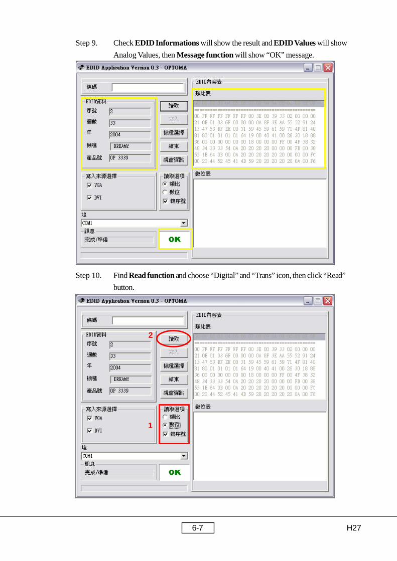
Step 9. Check EDID Informations will show the result and EDID Values will show
Analog Values, then Message function will show “OK” message.
Step 10. Find Read function and choose “Digital” and “Trans” icon, then click “Read”
button.
1
2

H276-8
Step 11. Check EDID Informations will show the result and EDID Values will show
Digital Values, then Message function will show “OK” message.
Step 12. Click “Exit” button to close the EDID program.

H277-1
Appendix A
Serial Number System Definition
Serial Number for Projector
EX: O82H433T0AAAA0002
This label “O82H433T0AAAA0002” represents the whole serial number
for H27, including Ver. 1st of BIOS and Ver. 1 of PCB Board. Both mechanical
and optical version are 1st. In addition, panel vendor is T. It’s produced on 33-week
of 2004 for universal area and its serial code is 0002.
A BBB Y WW C D BEMO EEEE1 2 3 4 5 6 7 8
1
2
3
4
5
6
7
8
: O = Optoma
: Product Code (ex: 82H= H27)
: Y = Last Number of the Year (ex: 2002 - 2, 2003 - 3)
: Week of Year
: Panel Vendor Code
: Electrical Classification (1=110V, 2=220V, 0=Universal)
: B = BIOS Version, E = PCB Board Version,
M = Mechanical Version, L = Location of Manufacture
: Serial Code (from 0001~)

H277-2
Appendix B Board S/N Coding
A B XXXXXXXXXX C XXX XXXX
ID
Vendor Code
P/N
Revision
*Date Code
S/N
B. DMD BD
C. MAIN BD
*Date Code : Year(1 digit)+Week(2 digits)
H277-3
Appendix C DLP Composer LiteSetup Procedure
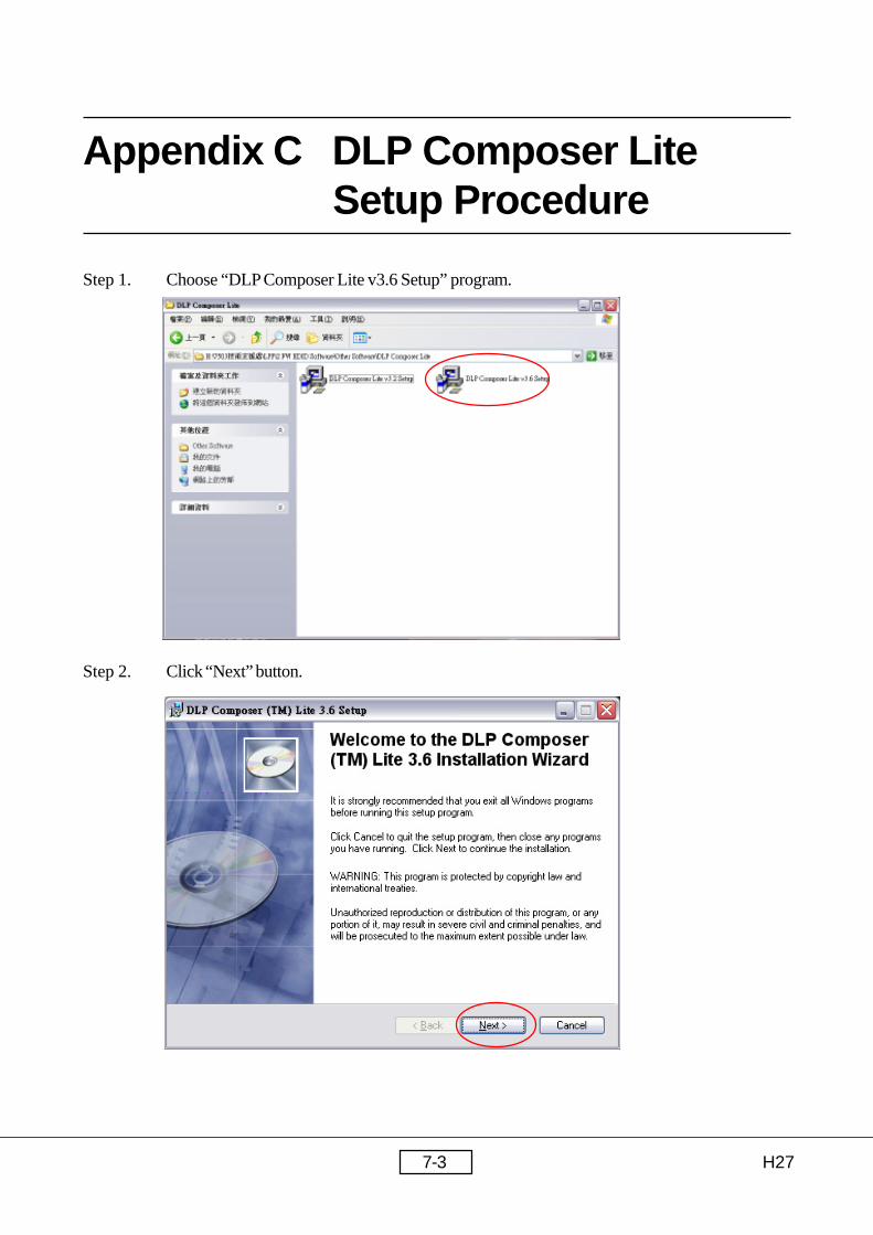
Step 1. Choose “DLP Composer Lite v3.6 Setup” program.
Step 2. Click “Next” button.

H277-4
Step 3. Reading the “License Agreement” rules, choose “I accept and agree to be bound by all the
terms and conditions of this License Agreement” icon, then click “Next” button.
1
2
3

H277-5
Step 4. Click “Next” button.
1
2
Step 5. Choose “All” icon, then click “Next” button.

H277-6
Step 6. Click “Next” button.
Step 7-1. The program is executing “Initializing” status.

H277-7
Step 8. Click “Finish” button , then click “Yes” button to restart your computer.
Step 7-2. If the screen is show the below message, please choose “Ignore” button.
H277-8
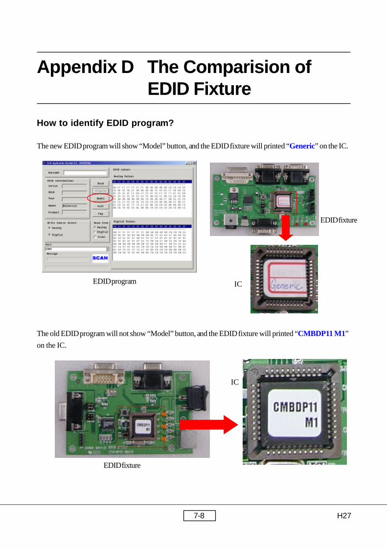
Appendix D The Comparision ofEDID Fixture
How to identify EDID program?
The new EDID program will show “Model” button, and the EDID fixture will printed “Generic” on the IC.
The old EDID program will not show “Model” button, and the EDID fixture will printed “CMBDP11 M1”
on the IC.
EDID program
EDID fixture
EDID fixture
IC
IC

H277-9
*Reader’s Response*
Dear Readers:
Thank you for your backing our service manual up. In order to refine our content of theservice manual and satisfy your requirement. We expect you can offer us some preciousopinions for reference.
Assessment:
:emaN :eltiT
:ynapmoC
:ddA
:leT :xaF
:liam-E
metI tnellecxE dooG riaF daB
tnetnoClaunaMecivreS.1
tuoyaLlaunaMecivreS.2
gnitsildnamrofehT.3
tinU tnellecxE dooG riaF daB
noitcudortnI.1
erudecorPylbmessasiD.2
gnitoohselbuorT.3
erudecorPtnemngilA&tseTnoitcnuF.4
erudecorPedargpUerawmriF.5
erudecorPni-yekCDD.6
xidneppA.7
B. Are you satisfied with the H27 service manual?
C. Do you have any other opinion or suggestion about this service manual?
Reader’s basic data:
After your finishing this form, please send it back to Coretronic Customer ServiceDept. by fax: 886-3-563-5333.
A. What do you think about the content after reading H27 Service Manual?