model free control design for a semi-active suspension of a
TRANSCRIPT

Model free control design for a semi-active suspension ofa passenger car
C. Lauwerys, J. Swevers, P. SasK.U.Leuven, Department of Mechanical Engineering,Division PMA,Celestijnenlaan 300 B, B-3001, Heverlee, Belgiume-mail: [email protected]
AbstractComfort and road handling in passenger cars can be improved by including a semi-active suspension system,controlled by online varying the damping based on measurements of the car motions. The selection ofan appropriate control structure is crucial, since it determines the complexity of the control design andparameter tuning process. Model based control requires the identification of a physical or black-box model ofthe car and semi-active suspension dynamics, which is not straightforward and time-consuming, especiallywhen these dynamics are highly nonlinear and strongly coupled. Model free controllers, such as neuralnetworks, can be hard to train or intuitively fine tune manually since its control parameters have no physicalmeaning. This paper presents a flexible model free control structure based on physical insights in the car andsemi-active suspension dynamics used to linearize and decouple the system, such that decentralized linearfeedback control can be applied. The resulting controller can be tuned online intuitively using a limitednumber of physically interpretable parameters.
KEY WORDSautomotive, semi-active suspension, model free control
1 Introduction
Comfort and road handling performance of a passenger car are mainly determined by the damping char-acteristic of the shock absorbers. Passive shock absorbers have a fixed damping characteristic determinedby their design. Depending on the road excitation, however, it is desirable to adjust this characteristic toincrease performance. Semi-active and active suspension systems offer the possibility to vary the dampercharacteristics along with the road profile e.g. by changing the restriction of one or two current controlledvalves or by changing the viscosity of a magneto rheological fluid. An active shock absorber has the addi-tional advantages that negative damping can be provided and that a larger range of forces can be generated atlow velocities, thereby potentially allowing an increase in system performance. Semi-active suspensions onthe other hand are less complex, more reliable and commercially available. They do not require an externalpower source (e.g. hydraulic pump) and are more safe because they can only dissipate energy and thereforecannot render the system unstable.
Literature describes several linear and nonlinear techniques to control a car using an active or semi-activesuspension. Karnopp and Crosby (1974),Butsuen (1989) and Esmailzadeh and Taghirad (1995) applylin-ear control strategies based on linear physical car models consisting of lumped masses, linear springs anddampers, and a shock absorber modelled as an ideal force source. Real car dynamics are much more complexand active shock absorbers are not ideal force sources but have a complex nonlinear dynamic behavior. Theseunrealistic assumptions make these linear control approaches less appropriate for practical applications.
75
Nonlinear control strategies such as linear parameter varying gain scheduling (Fialho and Balas, 2002),(Szasziet al., 2002), backstepping (Lin and Kannellakopoulos, 1997) and adaptive control (Alleyne and Hedrick,1995),(Zhan and Alleyne, 2002), have been applied to active suspension systems. These controllers arebased on a nonlinear physical car and damper model which have a large number of parameters. The experi-mental identification of these model parameters is a complex problem. In addition, the design and tuning ofthe above mentioned nonlinear controller is not straightforward. Basically the use of nonlinear models andcontrollers lead to very time-consuming designs, since no standard techniques or software tools are available.
Lauwerys et al. (2003) present a practical, experimental approach using linear identification and robust con-trol techniques on an active suspension of a quarter car test rig. A linear robustly performant controller wasobtained usingµ-synthesis based on an experimentally identified linear model of both the active suspensionand the quarter car dynamics. The relatively simple construction of the test-rig and the linearity of the ac-tive suspension made it possible to apply linear identification and control design techniques. The dynamicsof a real car are much more complex and a semi-active suspension behaves quite differently then an activesuspension: it becomes uncontrollable when the rattle velocity1 is zero. Because of these two reasons, thetechniques developed in (Lauwerys et al., 2003) are not extendable to this application.
While the above mentioned model based approaches may, in theory, yield optimal controllers for a certainshock-absorber and car model, their application to a full car and highly nonlinear semi-active shock-absorberis complex or even infeasible.
This paper presents a model free control structure that does not directly aim at optimality, but incorporatesmany physically interpretable parameters that can be easily tuned online according to guidelines given bytest-pilots and based on test-results. This approach is based on physical principles of semi-active shock-absorbers and cars in general, but does not require a model of its dynamics. Therefore it is applicable to anysemi-active or active suspension system and any type of car.
The semi-active suspension hardware, the available sensor signals, the car and the hydraulic shaker aredescribed in Section 2. Sections 3 and 4 discuss the systems linearization and decoupling. The structure ofthe controller, consisting of several feedback and feedforward modules, is explained in Section 5. Each ofthese modules tackles a particular comfort or handling issue. Section 6 discusses the manual and adaptivetuning of the control parameters resulting from this approach. Final conclusions are given in Section 7.
2 Hardware description
2.1 Semi-active shock-absorber
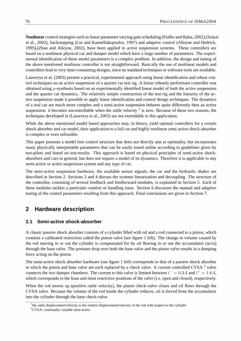
A classic passive shock absorber consists of a cylinder filled with oil and a rod connected to a piston, whichcontains a calibrated restriction called the piston valve (see figure 1 left). The change in volume caused bythe rod moving in or out the cylinder is compensated for by oil flowing in or out the accumulator (accu)through the base valve. The pressure drop over both the base valve and the piston valve results in a dampingforce acting on the piston.
The semi-active shock absorber hardware (see figure 1 left) corresponds to that of a passive shock absorberin which the piston and base valve are each replaced by a check valve. A current controlled CVSA2 valveconnects the two damper chambers. The current to this valve is limited betweeni− = 0.3A andi+ = 1.6A,which corresponds to the least and most restrictive positions of the valve (i.e. open and closed), respectively.
When the rod moves up (positive rattle velocity), the piston check-valve closes and oil flows through theCVSA valve. Because the volume of the rod inside the cylinder reduces, oil is forced from the accumulatorinto the cylinder through the base check-valve.
1the rattle displacement/velocity is the relative displacement/velocity of the rod with respect to the cylinder2CVSA: continually variable semi-active
76 PROCEEDINGS OFISMA2004

pistoncheckvalve
basecheckvalve
CVSAvalve
F v
+
pistonvalve
basevalve
accu
F v
+rod
cylinder
piston
accu
0.20.4
0.60.8
11.2
1.41.6
−2
−1
0
1
2−6000
−4000
−2000
0
2000
4000
6000
8000
Current [A]Velocity [m/s]
Forc
e [N
]
Figure 1: Working principle of a passive and semi-active shock-absorber (left). Semi-active shock absorberdamping characteristic relating the damper force to the control current and the rattle velocity (right)
When the rod moves down (negative rattle velocity), the piston check-valve opens. Because the volume ofthe rod inside the cylinder increases, the base check-valve closes and oil flows from the cylinder into theaccumulator through the CVSA valve.
Figure 1 (right) shows a measured velocity-force damping characteristic for different currents of the con-sidered semi-active shock-absorber. A low/high current to the CVSA valve corresponds to a small/largerestriction yielding a low/high damping ratio. This characteristic is obtained experimentally by applying asinusoidal rattle displacement signal for different settings of the control current to the CVSA valve.
2.2 Passenger car
A passenger car equipped with 4 semi-active shock-absorbers is available as a test-vehicle. Figure 2 showsthe car on an 4 hydraulic shakers which are capable of independently exciting the 4 wheels of the car with adesired road profile.
Figure 2: Picture of the passenger test-car on the hydraulic shaker
The body acceleration of the car is measured using 4 accelerometers mounted on the 4 corners of the chassis.Also the rattle displacement of all 4 shock-absorbers is measured using linear displacement sensors. For thistest-setup, the disturbance inputs of the system are the displacement of the shakers under the wheels of thecar. The control inputs are the currents to the 4 semi-active shock-absorber CVSA valves. The developedcontrollers are implemented on a dSpace 1003 controller board located in the trunk of the car.
ACTIVE SUSPENSIONS 77

3 Feedback linearization
The goal of feedback linearization is to transform the original control inputs of the system (the currents tothe semi-active shock-absorber CVSA valves) into virtual control inputs, in order to linearize the dynamicrelation between these new control inputs and the outputs of the system to be controlled (the measured bodyaccelerations). If the relation between the system inputs and outputs is linear (or sufficiently linear), controldesign and tuning simplifies since well known and CACSD-supported linear control design techniques canbe applied successfully.
When this transformation includes a physical damper model (e.g. Fialho and Balas (2002), Szaszi et al.(2002), Lin and Kannellakopoulos (1997), Alleyne and Hedrick (1995) and Zhan and Alleyne (2002)), thenew control input corresponds to the damper force. This paper presents an alternative transformation, usinga bilinear damper model, which results in another new control input that isnot the damper force, but which,however, results in a better linearization of the system.
3.1 Combining feedback linearization and linear control
In order to explain how feedback linearization and linear control are combined, only one corner of the car isconsidered. The shock absorber generates a forcefd depending on the rattle velocityvr and the damper valvecurrentiv. The disturbance input is the road displacementxa. The measured output is the body accelerationab. To control the body of the car, i.e. to reduce the body acceleration, a nonlinear controller is required thatfeeds back the body accelerationab, to the damper control currentiv (see Figure 3 left).
nonlinearcontroller
damper
ab
vr
xa
fd
iv
car
abiv
car
damper
ab
vr
xa
fd
iv
fc
iv vrlinearizingcontroller
linearcontroller
abfc
Figure 3: Control schemes representing the controller and the car and damper dynamics. Left: originalcar and damper system controlled by a nonlinear controller which calculates a damper currentiv from ameasured body accelerationab. Right: feedback linearized system controlled by a linear controller whichcalculates a desired damper force from a measured body acceleration.
The design and tuning of such a nonlinear controller is not straightforward. Since the semi-active shockabsorber is the most nonlinear element of the system, a linearizing controller is introduced, which calculatesan appropriate damper currentiv, such that a desired damper forcefc is realized for the given rattle velocityvr (see Figure 3 right). The desired damper forcefc is generated using a linear controller based on themeasured body accelerationab.
The linearizing controller is based on an inverse damper characteristic. Two different characteristics are con-sidered: the measured velocity-force characteristic shown in Figure 1 (right), which represents a simplifiedphysical damper model (see Section 3.2), and an analytically derived bilinear characteristic (see Section 3.3).
78 PROCEEDINGS OFISMA2004

The quality of both linearizing controllers is verified by checking the linearity of the transformed system (up-per block of right scheme in Figure 3).
3.2 Linearizing controller based on physical damper model
The classic approach to feedback linearization is to use a physical model. In this application the physicalmodel is a simplified 2D-lookup table (see Figure 1 right) which relates the damper forcefd to the controlcurrentiv and the rattle velocityvr. The inverse model is obtained by using 2D-interpolation techniquessuch that the damper currentiv can be calculated from the rattle velocityvr and the desired damper forcefc.
3.3 Linearizing controller based on bilinear damper characteristic
A semi-active shock absorber is a device that delivers a forcefc related to the rattle velocityvr and the controlsignaliv (equation 1). A bilinear approximation of this relation (equation 2) can be simplified (equation 3)by setting coefficientsF0 andF10 to 0 since a semi-active shock absorber cannot deliver any force whenthe rod is not moving (vr = 0). Equations 4 and 5 show the forward and inverse damper model similarityrelations. Based on this bilinear approximation, the damper force is linearly related to the product of therattle velocity and the biased control signal.
fc = F (vr, iv) (1)
fc = F0 + vrF01 + ivF10 + vrivF11 (2)
fc = vrF11(F01F11
+ iv) (3)
fc ∼ vr(i0 + iv) (4)
iv ∼ fc
vr− i0 (5)
Since a scaling is a linear operation that is compensated for by the linear controller, a new inputfc can becreated which is equal to the product of the rattle velocityvr and the biased control currentiv + i0. Thisinput no longer has the physical dimension of a damper force. Therefore it is called avirtual damper force.Note that this linearizing controller contains only one parameteri0, the control current bias, around whichthe controller will operate.
3.4 Linearizing controller comparison
To check and compare the performance of the linearizing controllers, the following experiment was setup.The test car was placed on the dynamic shakers and excited with the following signals:
• Uncorrelated pink noise road profile displacement signals to the 4 shakers under the wheels of the car.
• Uncorrelated white noise currents to the 4 CVSA valves of the semi-active shock absorbers.
The following signals where measured:
• The 4 accelerometer signals on the 4 corners of the car.
• The 4 rattle displacements of the 4 shock absorbers.
The 4 (virtual) damper forces were calculated offline based on the physical and the bilinear damper models.
Note that the performance of the damper models isnot validated by comparing the real (measured) and thecalculated (virtual) damper forces, since reproduction of this force is not the issue here and moreover since
ACTIVE SUSPENSIONS 79

the bilinear model produces a virtual damper force which no longer has this physical meaning since it hasbeen scaled and offset. The intention was to calculate a signal that is more linearly related to the bodyacceleration then the original control signal. Figure 4 shows the multiple coherence (Bendat and Piersol,1980) between the calculated damper forces, based on the physical and the bilinear model, and the bodyacceleration measured on one of the corners of the car. The coherence obtained with the bilinear model is
10−1
100
101
102
0
0.1
0.2
0.3
0.4
0.5
0.6
0.7
0.8
0.9
1
Frequency (Hz)
Coh
eren
ce
physicalbilinear
Figure 4: Linearity comparison based on the multiple coherence of the feedback linearized systems using aphysical and bilinear damper characteristic
higher, therefore indicating a more linear dynamic behavior, then the one obtained with the physical dampermodel.
The problem with the physical damper model is that it tries to compensate for the nonlinear current-velocity-force characteristics of the shock-absorber, which is much more complex then the lookup table in Figure 1(right). This lookup table was obtained with specific harmonic excitation signals for a range of fixed currentsettings. However, the response of a nonlinear system can be amplitude dependant. Therefore, the model isonly valid for excitation signals with similar amplitude levels to the ones that were used for its identification.The bilinear model on the other hand does not include these nonlinear characteristics but implements abilinear approximation which turns out to be more linearizing for broadband excitation signals, such asstochastic road excitations. Note that this bilinear damper model includes only one parameteri0 while thelookup table damper model consists of a large amount of data points to describe the nonlinear characteristicsof the damper.
4 Modal decoupling
The system as described in section 2 is a 4-by-4 multiple-input multiple-output (MIMO) system whichrequires a 4-by-4 MIMO controller (see figure 5). The control inputs of the system (outputs of the controller)are the virtual forces of the semi-active shock-absorbersfcd. The transformation of these virtual forces intocontrol currents is not considered in this section, and also not shown in figures 5 and 7. The measured outputsof the system (inputs of the controller) are the body accelerations at the 4 corners of the carac
b.
Figure 6 shows the measured frequency response function (FRF) matrix of this system. The relatively largemagnitude of the off-diagonal elements with respect to the diagonal elements indicates a strong coupling.
A static decoupling matrixD (see equation 6) and its pseudo-inverseD† are used to decouple the systeminto its modal motions heave, roll and pitch, which are then controlled by amodal (diagonal) controller(see figure 7 right). The transformed control inputs of the system (outputs of the controller) are 3 virtualmodal forces acting on the car through the 4 semi-active shock-absorbersfdd . The transformed outputs of
80 PROCEEDINGS OFISMA2004

xxxx
xxxx
xxxx
xxxx
coupledsystem
xxxx
xxxx
xxxx
xxxx
full MIMOcontroller
fdc
abc
Figure 5: Controller scheme for the 4-by-4 coupled system
the system (inputs of the controller) are the 3 modal motions of the caradb.
D =
+1 +1 +1 + δ +1 + δ+1 −1 +1 + δ −1− δ+1 +1 −1− δ −1− δ
(6)
A perfectly symmetric car would be decoupled by the transformation matricesD andD† with δ = 0. Thecolumns of this matrix correspond to a location of the sensors on the car: front-left, front-right, rear-left,rear-right. The rows represent the modal motions: heave (all in phase), roll (left in anti-phase with right),pitch (front in anti-phase with rear).
Figure 8 shows the measured FRF matrix of this decoupled system, withδ = 0. The relative magnitudeof the off-diagonal elements is significantly smaller indicating less coupling allowing decentralized control.Based on the FRF matrices in Figures 6 and 8 it is not possible to conclude whether values forδ 6= 0 wouldlead to more optimal decoupling for control. Thereforeδ is introduced as a control parameter that can betuned online in order to achieve symmetric car dynamics as a result of the longitudinally eccentricity of thecenter of gravity.
5 Control strategies
The linear controller consists of several feedback and feedforward modules, each tackling a specific comfortor handling issue. The output of all modules are summed to a desired modal virtual damper force.
5.1 Integral feedback control for comfort improvement
The goal is to suppress the modal motions of the car to increase the passengers comfort. The feedbacklinearization controller and modal decoupling transformations allow to directly specify desired modal forces,to be delivered by the shock-absorbers, from measured modal motions. Based on the skyhook principle( Karnopp and Crosby (1974)) the diagonal modal controllers consist of 3 first order low-pass filters ofwhich the bandwidthfb and gain can is tuned online to meet on optimal trade-off between desired comfortspecifications and input saturation.
5.2 Damping adjustment for optimal road handling
Wheelhop is a resonance mode where the wheels of the car move with large amplitude with respect to theroad while the car body remains relatively still. This phenomenon deteriorates the handling performance ofthe car because of the large tire contact force variations. The wheelhop mode can be damped by increasingthe control current biasi0 (see Equation 5) around which the control currents are varied.
ACTIVE SUSPENSIONS 81

1 10
From: fdrr
1 10
From: fdrl
1 10
From: fdfr
1 10−40−20
02040
To: a
brr
−40−20
02040
To: a
brl
−40−20
02040
To: a
bfr
−40−20
02040
From: fdfl
To: a
bfl
Bode Diagram
Frequency (Hz)
Mag
nitu
de (d
B)
Figure 6: Frequency response function matrix of the 4-by-4 coupled system from the virtual forces (fd) tothe body accelerations (ab) at the 4 corners of the car (fl:front-left, fr:front-right, rl:rear-left, rr:rear-right)
5.3 Steering angle feedforward control
When driving the car in a turn, it will roll because of the centrifugal force, which is proportional to the drivingvelocity squared and the curvature of the turn. This roll motion is compensated for using a feedforwardcontroller, which adds a modal roll force to the desired damper forces, opposite to the roll motion caused bythe turn and proportional to the measured driving velocity squared and the steering angle.
5.4 Throttle and break pedal feedforward control
When accelerating or braking, the car will pitch respectively backward and forward, proportional to theimposed lateral acceleration. This pitch motion is compensated for using a feedforward controller, whichadds a modal pitch force to the desired damper forces. This additional desired pitch force is proportional tothe measured breaking force and the desired wheel torque (both available on the CAN bus of the car).
6 Controller parameter tuning
6.1 Manual parameter tuning
No model is available to tune the controller e.g. in simulation. The translation of subjective issues likecomfort and road handling, into classical control specifications, e.g. bandwidth and settling time, is verydifficult and ambiguous. Therefore, the developed controller is equipped with a number of parameters thatcan be tuned separately on-line, based on comments provided by an experienced test-pilot driving the carover calibrated test tracks. All tunable parameters have a physical interpretation such that their effect on
82 PROCEEDINGS OFISMA2004

xxxx
xxxx
xxxx
xxxx
coupledsystem
xoo
oxo
oox
modalcontroller
fdd
abd
DDy
couplingmatrix
decouplingmatrix
fdc
abc
Figure 7: Controller scheme where the coupled 4-by-4 system is modally decoupled by the static transfor-mation matricesD andD† and controlled by a diagonal 3-by-3 modal controller
the total behavior of the suspension is clear. The following discusses the different control parameters, theirphysical interpretation and their effect on the behavior of the car.
• The modal decoupling matrixD contains one parameterδ representing the longitudinal offset of thecenter of gravity. This parameter is tuned in order to get a balanced car response where the front andrear dynamics behave similarly.
• The integral feedback controller, which consists of 3 first-order low-pass filters, contains 6 parame-ters: 3 gains and 3 bandwidths. Increasing these gains and bandwidths improves the low-frequencyattenuation of the modal motions of the car up to a certain point where they also start to deteriorate thehigh-frequency harshness.
• The bilinear damper model used to linearize the system dynamics, includes the rattle velocity to cal-culate the control currents based on the desired virtual damper force. Therefore the measured rattledisplacement is differentiated and filtered with a low-pass filter in order to prevent high-frequencynoise amplification. The bandwidth of this filter is an important parameter which is tuned to optimizethe trade-off between controller bandwidth and noise sensitivity.
• The control current biasi0 (see Equation 5) determines the average amount of damping in the systemand is mainly tuned to optimize the handling performance of the car. Increasing this value providesthe car with a better tire force contact but deteriorates the passengers comfort. Experimental tuningshowed that the optimal value depends on the type of road: a smooth road allows for a soft settingwhile a rough road requires a harder setting.
6.2 Adaptive parameter tuning
The control current biasi0 resulting in the optimal compromise between comfort and road handling dependson the roughness of the road. The goal is to limit the tire contact force variations in order to maintain acertain amount of handling performance, independently of the road input. Since these tire contact forcescannot be measured online, it is assumed that the average amount of kinetic energy of the wheels is relatedto the average amount of tire contact force variation. The absolute wheel velocity can be approximated bythe rattle velocity, since at wheelhop resonance, the body of the car remains relatively still with respect to thewheels. This leads to the following adaptive control law to maintain constant handling performance: adaptthe control current biasi0 such that the mean amount of kinetic energy of the wheels remains constant.
A measureE proportional to the (moving) average amount of kinetic energy of the wheels is calculatedonline by filtering the sum (of all 4 wheels) of the rattle velocitiesvr squared with a first order low-passfilter. The time-constantτ of this filter determines the time over which the average is calculated.
E =1
τs + 1(∑
v2r ) (7)
ACTIVE SUSPENSIONS 83

1 10
From: fdpitch
1 10
From: fdroll
1 10−20
0
20
40
To: a
b pitc
h
−20
0
20
40
To: a
b roll
−20
0
20
40
From: fdheave
To: a
b heav
e
Bode Diagram
Frequency (Hz)
Mag
nitu
de (d
B)
Figure 8: Frequency response function matrix of the 3-by-3 decoupled system from the virtual modal forces(fd) to the modal body accelerations (ab)
For a certain type of road and a fixed value of the control current biasi0, a time constantτ exists for whichthe average amount of kinetic energy of the wheelsE converges to a constant value (within given bounds).Increasingi0, resulting in a harder shock absorber, will decreaseE. The car, seen as a systemG with controlinput i0 and measured outputE, can be modelled as a first order system with time constantτ and a negativeDC-gainA (see equation 8). A proportional feedback controllerP results in a new first order system with atime-constantτc = τ
1+PA and a DC-gainAc = PA1+PA (see figure 9). The parameterP and the referenceE0
can be tuned to obtain a desired amount of road-independent handling performance.
G = Aτs+1 (8)
I0P
EG
E0
+
Figure 9: Adaptive controller to keep the averaged kinetic energy of the wheelsE, related to the averaged tirecontact force variation, at a constant levelE0 by controlling the control current biasi0 with a proportionalcontroller.
84 PROCEEDINGS OFISMA2004

7 Conclusions
The generic controller structure presented in this paper is derived based on physical insight in car and semi-active suspension dynamics without explicitly using a model. The control structure consists of three basicparts. First the system is linearized by transforming the original current control inputs to virtual damper forceinput signals. Experimental results show that this linearization is improved if a bilinear damper characteristicis used instead of a nonlinear characteristic based on a physical model. Then the system dynamics aredecoupled into their modal components using static decoupling matrices. Although the actual car dynamicsare not symmetric nor statically decouplable, the off-diagonal elements of the FRF-matrix are sufficientlysmall with respect to the diagonal elements after static decoupling. A single parameter allows to fine tune thelongitudinal offset of the center of gravity in order to achieve symmetric car dynamics. Finally this linearizedand decoupled system is controlled by a linear decentralized controller, which consists of several modulesthat all tackle a specific comfort or handling issue. All parameters resulting from this model free controlstructure have physical meaning and therefor can be intuitively tuned online based on comments of a test-pilot. Because the optimal average damping of the system depended on the roughness of the road excitation,an adaptive controller was designed to regulate the control current bias.
Acknowledgement
The financial support by the Flemish Institute for Support of Scientific and Technological Research in Indus-try (IWT) is gratefully acknowledged. This research is sponsored by the Belgian programme on Interuniver-sity Poles of Attraction, initiated by the Belgian State, Prime Minister’s Office, Science Policy Programming(IUAP).
References
Alleyne, A., Hedrick, J. K., 1995. Nonlinear adaptive control of active suspensions. IEEE Transactions onControl Systems Technology 3 (1), 94–101.
Bendat, J. S., Piersol, A. G., 1980. Engineering applications of correlations and spectral analysis. John Wiley& Sons, New York.
Butsuen, T., June 1989. The design of semi-active suspensions for automotive vehicles. Ph.D. thesis, Mas-sachusetts Institute of Technology.
Esmailzadeh, E., Taghirad, H., 1995. State-feedback control for passenger ride dynamics. Transactions ofthe Canadian Society for Mechanical Engineering 19(4), 495–508.
Fialho, I., Balas, G. J., January 2002. Road adaptive active suspension design using linear parameter varyinggain-scheduling. IEEE transactions on control systems technology 10 (1), 43–54.
Karnopp, D. C., Crosby, M. J., 1974. Vibration control using semi-active force generators. Journal of Enge-neering for Industry 96, 619–626.
Lauwerys, C., Swevers, J., Sas, P., 2003. Control of an active suspension of a quarter car. Some paper orjournal ? (?), ?–?
Lin, J.-S., Kannellakopoulos, I., 1997. Road adaptive nonlinear design of active suspensions. Proceedings ofthe American Control Conference , 714–718.
Szaszi, I., Gaspar, P., Bokor, J., 2002. Nonlinear active suspension modeling using linear parameter vary-ing approach. Proceedings of the 10th IEEE Mediterranean Conference on Control and Automation,MED2002,Portugal THA (5-4).
Zhan, Y., Alleyne, A., 2002. A practical and effective approach to active suspension control. 6th InternationalSymposium on Advanced Vehicle Control, AVEC 02, Hiroshima, Japan .
ACTIVE SUSPENSIONS 85

86 PROCEEDINGS OFISMA2004