a new modified parametric algebraic …€¦ · ... and therefore the design of a mechanical...
TRANSCRIPT
International Journal of Automobile Engineering
Research and Development (IJAuERD)
ISSN 2277-4785
Vol. 3, Issue 1, Mar 2013, 1-14
© TJPRC Pvt. Ltd.
APPLICATION OF A NEW MODIFIED PARAMETRIC ALGEBRAIC MODEL FOR
MAGNETORHEOLOGICAL DAMPER IN VEHICLE SEMI-ACTIVE SUSPENSION
SYSTEM
LOGANATHAN BALAMURUGAN1 & JEYARAJ JANCIRANI
2
1Research Scholar, Anna University, Chennai, Tamilnadu, India
2Assistant Professor, Anna University, Chennai, Tamilnadu, India
ABSTRACT
The purpose of this paper is to present a new modified parametric algebraic model for MR damper in
controlling the semi-active suspension system. Except for its accuracy, modified algebraic model is additionally more
preferable in terms of its low computational expenses compared to differential modified Bouc-Wen’s model that is
extremely computationally demanding. The control part consists of two nuzzled controllers, one the system controller
that generates the required damping force, and other the damper controller that adjusts the voltage level to MR damper
thus to track the required damping force. For the system controller a model reference skyhook Sliding Mode
Controller (SMC) is employed and for damper controller a continuous state algorithm is constructed to determine the
input voltage thus to gain the required damping force. Along with the proposed modified algebraic model and a
suitably designed skyhook SMC with continuous-state damper controller, the MR damper is applied to a quarter-car
suspension model and therefore the performance of the semi-active controller is compared to the active controller and
with the prevailing passive suspension system. A computer simulation is executed to prove the effectiveness and
robustness of the semi-active control approach.
KEYWORDS: Semi-Active Suspension System, Skyhook Sliding Mode System Controller, Continuous-State Damper
Controller and Quarter-Car Suspension Model
INTRODUCTION
A suspension, in its more classical and traditional configuration is constituted by three main components:
• An elastic component (typically a coil spring), that delivers a force proportional and opposite to the suspension
elongation; this part carries the complete static load.
• A damping component (typically a hydraulic shock absorber), that delivers a dissipative force proportional and
opposite to the elongation speed; this part delivers a negligible force in steady-state, however plays a vital role with in the
dynamic behaviour of the suspension.
• A set of mechanical components that links the suspended (sprung) body to the unsprung mass. Roughly speaking,
the suspension could be a mechanical low-pass filter that attenuates the consequences of a disturbance (e.g. an irregular
road profile) on an output variable. The output variable is usually the body acceleration when comfort is that the main
objective; the tire deflection when the design goal is road-holding. For passive suspension from Figure-1 it’s clear that
these two objectives are somehow conflting the tuning and therefore the design of a mechanical suspension tries to search
out the most effective compromise between these two goals [1]. In this respect, the birth of electronic suspensions for the
car mass-market can probably be dated from the early Sixties, when Citroen introduced hydro-pneumatic suspensions [1],
which modified opened the way to the concept of “on-line” electronic adaptation of the suspension. Heavy power

2 Loganathan Balamurugan & Jeyaraj Jancirani
consumption, large and unsafe hydraulic systems, and unsure management of the safety issues: the fatal attraction for fully-
active electronic suspensions lasted solely a few years. They were banned in F1 competitions with in the early nineties, and
that they never had a big impact on mass-market automotive production [1]. Within the second half of the nineties, a new
trend emerged: it became clear that the best compromise of cost and performance lay in another technology namely, semi-
active suspensions. From the paper by Song and Ahmadian [2], it’s clear that the semi-active control system presented is
stable despite of the damping tuning approach. One among the most option of semi-active control systems is that they are
fail-safe. This suggests that if the control system fails for any reason (including power failure and sensor failure), the
system acts as a passive system. Therefore a semi-active suspension systems are getting more popular because they provide
both the reliability of passive systems and also the versatility of active systems without imposing heavy power demands.
Figure 1: Filtering Effect of a Passive Suspension: Example of a Road-to-Chassis Frequency
SEMI-ACTIVE SUSPENSIONS
Semi-active suspensions are an incredible mixture of appealing features; like negligible power-demand, safety,
low cost, low weight and significant impact on the vehicle performance. Many types of vehicle are equipped (or are being
equipped) with semi-active suspension. Such vehicles vary from small vehicles like motorcycles, snowmobiles, etc. to
massive off-road vehicles, passing through classic cars, and duty-vehicles like trucks, ambulances, fire-trucks, etc. [3–12].
It should particularly bear in mind the actual fact that the most semi-active control challenge lies within the dissipative
constraint of the damper control and not within the spring nonlinearities description [13]. Hence semi-active suspensions
are implemented by the use of controllable shock absorbers. The technologies out there are based mostly on devices with
variable orifices (electrohydraulic dampers) or on devices with fluids capable of varying their viscosity as a function of
electric or magnetic field (electro-rheological and magneto-rheological dampers). Recently, the semi-active suspension
based mostly on MR damper has attracted a lot of attention [14–17] due to its quick response characteristic to the applied
magnetic fields, in-sensitiveness to temperature variations or impurities within the fluid, obtainment of convenient power
and broad control bandwidth. However, the practical use of MR dampers for control is considerably hindered by its
inherently hysteretic and highly nonlinear dynamics. Therefore, a dynamic hysteresis model is required to simulate the
Application of a New Modified Parametric Algebraic Model for 3
Magnetorheological Damper in Vehicle Semi-Active Suspension System
hysteresis phenomenon of MR dampers. To this end, numerous models are proposed within the literature like parametric
viscoelastic-plastic model based mostly on the Bingham model [18], the Bouc–Wen model [19], non-parametric models
[20], and lots of. Additionally, theoretical and experimental researches have demonstrated that the performance of a semi-
active control system is also highly dependent on the selection of control strategy [21]. Therefore, some semi-active control
schemes are presented and compared in [22] and lots of other approaches, such as skyhook, ground-hook and hybrid
control [23], H∞ control [24], model-following sliding mode control [25], Neuro-fuzzy control [26] and observer-based
control [27] are evaluated in terms of their applicability in practice. Thus MR dampers in semi-active vehicle suspension
applications are determined by two aspects: one is that the accurate modelling of the MR dampers and the other is that the
choice of an appropriate control strategy.
In this paper, the control of the stationary response of a quarter car vehicle model to random road excitation is
considered with semi-active MR dampers. The MR damper is modelled by the proposed modified algebraic model. Except
for its accuracy, modified algebraic model is additionally more preferable in terms of its low computational expenses
compared to differential modified Bouc-Wen’s model that is extremely computationally demanding. The control part
consists of two nuzzled controllers, one the system controller that generates the required damping force, and other the
damper controller that adjusts the voltage level to MR damper thus to track the required damping force. For the system
controller a model reference skyhook Sliding Mode Controller (SMC) is employed and for damper controller a continuous
state algorithm is constructed to determine the input voltage thus to gain the required damping force. Along with the
proposed modified algebraic model and a suitably designed skyhook SMC with continuous-state damper controller, the
MR damper is applied to a quarter-car suspension model and therefore the performance of the semi-active controller is
compared to the active controller and with the prevailing passive suspension system.
The rest of this paper is organised as follows. Section 3 outlines the description of the modelling of the MR
damper. Section 4 gives an overview of the quarter vehicle model. Section 5 describes the semi-active control system. The
results obtained for random road disturbance inputs are presented and discussed in section 6.
MODELING THE HYSTERETIC BEHAVIOR OF MR DAMPER
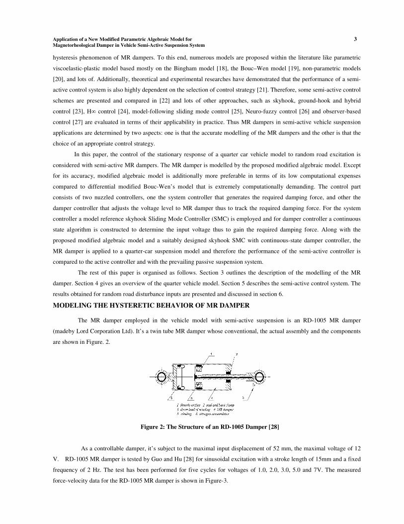
The MR damper employed in the vehicle model with semi-active suspension is an RD-1005 MR damper
(madeby Lord Corporation Ltd). It’s a twin tube MR damper whose conventional, the actual assembly and the components
are shown in Figure. 2.
Figure 2: The Structure of an RD-1005 Damper [28]
As a controllable damper, it’s subject to the maximal input displacement of 52 mm, the maximal voltage of 12
V. RD-1005 MR damper is tested by Guo and Hu [28] for sinusoidal excitation with a stroke length of 15mm and a fixed
frequency of 2 Hz. The test has been performed for five cycles for voltages of 1.0, 2.0, 3.0, 5.0 and 7V. The measured
force-velocity data for the RD-1005 MR damper is shown in Figure-3.

4 Loganathan Balamurugan & Jeyaraj Jancirani
Figure 3: Force Vs. Velocity of RD-1005 MR Damper at 2 Hz Sinusoidal Excitation [28]
The algebraic model proposed by Guo and Hu [28] is adopted and modified to provide more correct results. The
model is given by
1
0
0
2( ) ( ) tan { [ ( )
sgn( ( ))]}
b yF t f C x t f k x t
x x t
−= + +π
−
& &
& && (1)
Where F represents the damping force of the MR damper, f0 the preload of the nitrogen accumulator, Cb the
coefficient of hysteretic damping, fy the yielding force, k the damper coefficient, 0x&,
( )x t&and
( )x t&& are the hysteretic
velocity, the excitation velocity and acceleration of the piston within the damper, respectively. This mathematical model is
developed primarily based on some physical phenomena. Whereas the primary term is to represent the preload force of the
pressurized nitrogen gas within the accumulator, the second term is to explain the viscous force of the damper and the last
one is to replicate the observed hysteretic behaviour, respectively. The mathematical descriptions of the first two terms
come back from classical mechanics, whereas of the third one is developed primarily based on the definition of a
trigonometric arctangent function that best resembles the characteristic force–velocity curve of the damper. Further, the
two terms within the braces of the arctangent function are to account for the lag within the force response to a sinusoidal
excitation. In this model 2( ) sin( ), ( ) cos( ), ( ) sin( )x t a t x t a t x t a t= ω = ω ω = − ω ω& &&
where a is the displacement amplitude and ω
is that angular velocity. In equation (1) f0, Cb , fy , k, and 0x&
are
the unknown parameters and to be determined on the basis of experimental data by using least-square curve fitting
technique.
In order to validate the algebraic model, Guo and Hu [28] compared the measured damper force and the
predicted damper force obtained from the algebraic model are shown in Figure- 4
Figure 4: Force Vs. Velocity Comparisons between the Algebraic Model Predictions and Experimental Data
It is observed that there’s a general sensible agreement between the estimated and measured values apart from
higher voltage inputs of 5V and 7V at the highest excitation velocity of 200mm/s (see also Figure-5). The measured force-

Application of a New Modified Parametric Algebraic Model for 5
Magnetorheological Damper in Vehicle Semi-Active Suspension System
velocity data for the MR damper presented in Figure-3 suggests nonlinear dependence of the force on the applied voltage.
Starting from this point, the model given in Eq. (1) is modified by multiplying an incremental nonlinear voltage function in
order to improve the agreement.
0202
1
0 0
2 2
(( ) )0.16
2( ) tan { [ ( ) sgn( ( ))]}*
(1 )1
1
d b y
V a Ia I
f f C x t f k x t x x t
k k
ee
−
−− +
= + + −π
+ −+
+
& & & &&
(2)
The nonlinear incremental behaviour of the voltage is characterised by an asymmetric sigmoid function with a bias
within the lateral axis [29]. The function should also exhibit post-yield limiting behaviour of the damping force attributed
to the rheological properties of the MR fluid. The nonlinear voltage function k2 and a2 are positive constants and I0 is an
arbitrary constant representing the bias. The parameters are determined on the basis of experimental data by using least-
square curve fitting technique.
For instance, one arrives at the subsequent mathematical model of RD-1005 MR damper for model parameter estimates,
when 15a mm≤
and 2f Hzω
= =2π , respectively. Substituting
( )x t&=
cos( )a tω ω into equation (1) yields
2 1
1.04 1.1( 2.3)
1.51 2 710( sin( ), cos( ), ) 247 cos( ) tan
1 10.34 1d V V
f a t a t V a te e
−
− − −− ω ω ω ω = + ω ω +
π+ + (3)
0.2
40*{0.0725[ cos( ) sgn(sin )]}
1 1.81V
a t te
−ω ω − ω ∗
+ (0.00001)( 0.1375)(0.00001)(( ) 0.1375)
0.16
500 500(1 )
11
Ve
e
− −− −
+ −+
+ (4)
Figure 5: Hysteretic Loops of Damping Force of RD-1005 MR Damper with Respect to Velocity Obtained from
the Model given by Eq. (1) at Voltage Inputs of 5 and 7V

6 Loganathan Balamurugan & Jeyaraj Jancirani
Figure 6: Hysteretic Loops of Damping Force of RD-1005 MR Damper with Respect to Velocity Obtained from
the Model given by Eq. (2) at Voltage Inputs of 5 and 7V
It is obvious from Figure-6 that the proposed modified algebraic model removed the disagreement at the mention
higher voltage input higher velocity region. This is often presumably because of the impact of the multiplied incremental
nonlinear voltage function to the algebraic model. It had been inferred that the suggested modified algebraic model might
overcome the shortcomings of the original algebraic model. Except for its accuracy, modified algebraic model is also more
preferable in terms of its low computational expenses compared to differential modified Bouc-Wen’s model that is highly
computationally demanding. It’s hoped that the current improved model can aid to develop more practical control
strategies and algorithms for MR dampers.
SEMI-ACTIVE MR SUSPENSION SYSTEM
The schematic of the quarter car model with semi-active suspension provided by MR dampers is shown in Figure-7.
The MR damper is modelled by the modified algebraic model as within the previous section. The equations of motion of
the semi- active MR suspension system is given by
1 1 2 1 2 2 1 2 1 1
1
( ) ( ) ( )
d r
m z c z z k z z k z q
f F m g
= − − − − − −
+ − +
&& & &
(5)
2 2 2 2 1 2 2 1
2
( ) ( )
d r
m z c z z k z z
f F m g
= − − − −
− + +
&& & &
(6)
Where m2 is that the sprung mass of the vehicle body, m1 is that the unsprung mass, z2 is the absolute
displacement of the vehicle body, z1 is that the unsprung mass displacements, k2 is that the passive suspension stiffness, c2
is that the passive suspension damping coefficient, k1 is that the tyre stiffness, g is that the are the gravity acceleration, and
Fr is that the friction of suspension, q is that the road(random) excitations and fd is thatthe control force generated by the
MR damper. The passive components will guarantee a minimal level of performance and safety, whereas the semi-active
components will be designed to further improve the performance.
Figure 7: Semi-Active Suspension System-Quarter Car with MR Damper

Application of a New Modified Parametric Algebraic Model for 7
Magnetorheological Damper in Vehicle Semi-Active Suspension System
Defining the state variable
1 2 1 1 2[( ),( ), , ]
TX z q z z z z= − − & &
, then the state-equations and output-equations can be listed as follows:
X AX BQ EU= + +&
(7)
Y CX DQ FU= + +
(8)
Where,
1 2 2 2
1 1 1 1
2 2 2
2 2 2
0 0 1 0
0 0 1 1
0
k k c cA
m m m m
k c c
m m m
− − −=
− −
, 1
2
1 0 0
0 0 0
10 1
10 1
Bm
m
−
−=
,
2 2 2
2 2 2
0
1 0 0 0
0 1 0 0
k c c
m m m
C
− −
=
,
2
10 1
0 0 0
0 0 0
m
D
=
,
1
2
0
0
1
1
Em
m
= −
2
1
0
0
m
F
− =
r
q
Q g
F
=
&
, { }dU f=
,
2
1
2 1
z
Y z q
z z
= − −
&&
.
THE SEMI-ACTIVE CONTROL SYSTEM USING MR DAMPERS
The semi-active control system based primarily on an MR damper is illustrated as block diagram in Figure-8. The
plant is that the two degree-of-freedom semi-active suspension system as explained in previous chapter excluding the MR
damper. The control part consists of two nuzzled controllers. The system controller generates the required damping force
whereas the damper controller adjusts the voltage level to track the required force. Within the block diagram, the plant is
represented by the state space equation (7) and the MR damper has been modelled as given in section 2. The damping force
of MR damper is fd and the required damping force generated by the system controller is fc.
Figure 8: Block Diagram of Semi-Active Control System with MR Damper
System Controller: Skyhook Sliding Mode Controller
This section provides an summary of the system controller, that was derived in reference [30]. In designing a
Skyhook Sliding Mode Controller (SMC), the target is to consider the subsequent nth order non-linear system because the
controlled plant, and thus defined by the general state-space within the equation
( , , )x f x u t=& (9)
Where x∈Rn is that the state vector, n is that the order of the nonlinear system, and u ∈ Rm is that the control input, m
is that the number of inputs.

8 Loganathan Balamurugan & Jeyaraj Jancirani
A time varying surface s(t) is outlined within the state space R(n)
. S (e, t) is that the sliding surface of the hyper-
plane, which is given in equation (10) and shown in Figure-9.
1
( , ) *
nd
s e t edt
−
= + λ
(10)
In the 2-DOF active suspension system, we let n = 2, given that, because it is a second-order system.
s e e= + λ& (11)
Figure 9: Sliding Surface Design
Where velocity and acceleration of the vehicle body are selected as error (e) and change in error (e&
) feedback
signals for the 2-DOF SA suspension system control and λ is a positive constant that defines the slope of the sliding
surface.
From the above equation, the second-order tracking problem is currently being replaced by a first-order
stabilization problem within which the scalar s is kept at zero by means of governing condition [31].
21( )
2V s s=
(12)
This is obtained from the utiliation of Lyapunov stability theorem and it states that the origin is a globally
asymptotically stable equilibrium point for the control system. Equation shown on the top of is positive definite and its
time derivative is given in inequality,
( ) 0V s ss= <& &
(13)
To satisfy the negative definite condition, the system should satisfy the above shown inequality. If the inequality
equation is not satisfied means, the state of system deviates from the sliding surface. It is desirable that whenever the
system isn’t on the sliding surface, at a given instant of time it’s driven on the sliding surface and kept there. The variable s
will be driven to zero by means that actual control input u from the controller.
The controller design procedure consists of two steps. First, a feedback control law u is chosen to verify sliding
condition. However, so as to account for the presence of modelling imprecision and of disturbances, the control law needs
to be discontinuous across the s(t). If the implementation of the associated control switching is imperfect, this may lead to
chattering. Thus, in a second step, the discontinuous control law u is suitably smoothed to attain an optimal trade-off
between control bandwidth and tracking precision. The skyhook control will reduce the resonant peak of the sprung mass
quite considerably and therefore can achieve a good ride quality.By borrowing this concept to reduce the sliding chattering
phenomenon, as in Figure-10 shown, a soft switching control law is introduced to the major sliding surface switching
activity of control law that is to attain a sensible switch quality for the SkyhookSMC.

Application of a New Modified Parametric Algebraic Model for 9
Magnetorheological Damper in Vehicle Semi-Active Suspension System
Figure 10: Sliding Mode Surface Design with Skyhook Control Law
This can be done by stipulating the following condition.
0 tanh 0
0 0
skyhookSMC c
sc ss
u f
ss
− >
= = δ ≤
&
&
(14)
The variable of s is outlined in Equation (10), that contains the system information. It may be taken as a part of the
Skyhook SMC control law in Equation (13), where c0 is an assumed positive damping ratio for the switching control law.
The Skyhook SMC has to be chosen in such a way that the existence and also the reachability of the sliding-mode are both
guaranteed. Noting that δ is an assumed positive constant that defines the thickness of the sliding mode boundary layer [32].
The control system parameters employed in this research are identical as those used in [32] and are summarized in Table 1.
Table 1: System Controller Parameters
Parameter Symbol Value
SkyhookSMC damping
coefficient c0 -5000
Thickness of the sliding
mode boundary layer δ
28.1569
Sliding surface slope λ 10.6341
Damper Controller: Continuous-State Control
Force-tracking control of the MR damper model is performed employing a simple continuous-state control. The
continuous-state control of the MR damper was employed by [33, 34 and 35], within which a simple feedback control
strategy might linearize the response of the MR damper. To induce the MR damper to give roughly the corresponding
required control force, the command signal is chosen and described by the SIMULINK block diagram as in Figure-11.
Figure 11: Force Tracking Control of MR Damper
The damping force of MR damper is fed back with a gain B and compared to the required force. The resultant
error is scaled by a gain K. To make sure the damper cannot generate energy to the system, the controller function is
enabled solely when the direction of damping force and also the error have the same direction. Therefore it’s essential to
10 Loganathan Balamurugan & Jeyaraj Jancirani
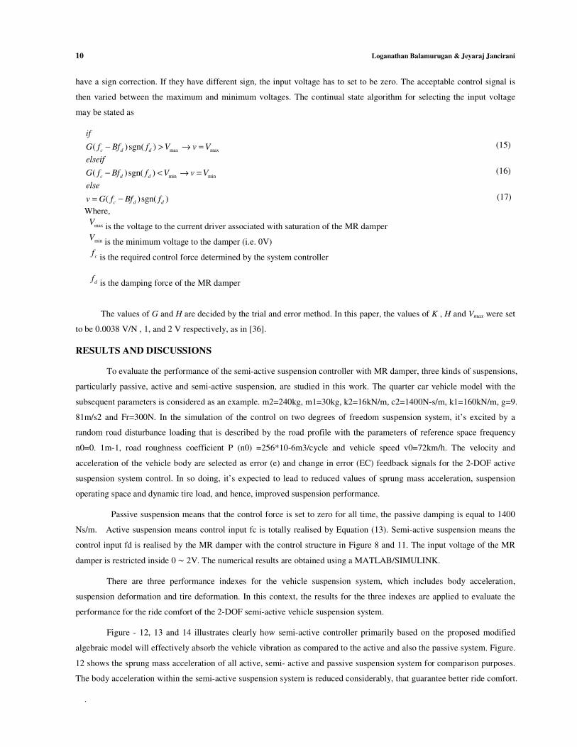
have a sign correction. If they have different sign, the input voltage has to set to be zero. The acceptable control signal is
then varied between the maximum and minimum voltages. The continual state algorithm for selecting the input voltage
may be stated as
max max( ) sgn( )c d d
if
G f Bf f V v V− > → = (15)
min min( )sgn( )c d d
elseif
G f Bf f V v V− < → = (16)
( )sgn( )c d d
else
v G f Bf f= − (17)
Where,
maxV
is the voltage to the current driver associated with saturation of the MR damper
minVis the minimum voltage to the damper (i.e. 0V)
cf
is the required control force determined by the system controller
df
is the damping force of the MR damper
The values of G and H are decided by the trial and error method. In this paper, the values of K , H and Vmax were set
to be 0.0038 V/N , 1, and 2 V respectively, as in [36].
RESULTS AND DISCUSSIONS
To evaluate the performance of the semi-active suspension controller with MR damper, three kinds of suspensions,
particularly passive, active and semi-active suspension, are studied in this work. The quarter car vehicle model with the
subsequent parameters is considered as an example. m2=240kg, m1=30kg, k2=16kN/m, c2=1400N-s/m, k1=160kN/m, g=9.
81m/s2 and Fr=300N. In the simulation of the control on two degrees of freedom suspension system, it’s excited by a
random road disturbance loading that is described by the road profile with the parameters of reference space frequency
n0=0. 1m-1, road roughness coefficient P (n0) =256*10-6m3/cycle and vehicle speed v0=72km/h. The velocity and
acceleration of the vehicle body are selected as error (e) and change in error (EC) feedback signals for the 2-DOF active
suspension system control. In so doing, it’s expected to lead to reduced values of sprung mass acceleration, suspension
operating space and dynamic tire load, and hence, improved suspension performance.
Passive suspension means that the control force is set to zero for all time, the passive damping is equal to 1400
Ns/m. Active suspension means control input fc is totally realised by Equation (13). Semi-active suspension means the
control input fd is realised by the MR damper with the control structure in Figure 8 and 11. The input voltage of the MR
damper is restricted inside 0 ∼ 2V. The numerical results are obtained using a MATLAB/SIMULINK.
There are three performance indexes for the vehicle suspension system, which includes body acceleration,
suspension deformation and tire deformation. In this context, the results for the three indexes are applied to evaluate the
performance for the ride comfort of the 2-DOF semi-active vehicle suspension system.
Figure - 12, 13 and 14 illustrates clearly how semi-active controller primarily based on the proposed modified
algebraic model will effectively absorb the vehicle vibration as compared to the active and also the passive system. Figure.
12 shows the sprung mass acceleration of all active, semi- active and passive suspension system for comparison purposes.
The body acceleration within the semi-active suspension system is reduced considerably, that guarantee better ride comfort.
.

Application of a New Modified Parametric Algebraic Model for 11
Magnetorheological Damper in Vehicle Semi-Active Suspension System
Figure 12: Sprung Mass Acceleration Response
Figure. 12 and 13 shows the suspension deflection and tire load of all active, semi- active and passive suspension
system for comparison purposes. The suspension deflection and tyre load is also smaller using the semi-active controller
based on the proposed modified algebraic model, that guarantee better road holding.
Figure 13:Suspension Stroke Response
Figure 14:Tyre Load Response
Thus in overall from Figure.(12-14), it may be seen that both active and semi-active suspension systems are able to
comparatively lower magnitude for vehicle body acceleration, suspension deflection and tire load within the time domain
in comparison with the passive suspension system. Using the presented control structure in Figure-8, the semi-active
suspension system in conjunction with the MR damper can achieve a control performance that’s almost like that of the
active suspension system apart from a little deterioration due to the passivity and the limitation constraints. It demonstrates
the effectiveness of the semi-active controller with MR damper for vibration suppression of the suspension system.
Figure.15 shows the psd(power spectral density) of sprung mass acceleration for various suspension systems. The
vehicle model considered for the analysis is two degrees of freedom vehicle model, thus two predominant frequencies are
observed within the Figure-15. It may be seen that, the sprung mass acceleration characteristics as compared to the passive

12 Loganathan Balamurugan & Jeyaraj Jancirani
suspension, is improved by the active and semi-active suspension system at both the predominant frequencies.
Figure 15: Sprung Mass Acceleration Psd
All these results indicate that the semi-active controller presented in this paper dissipate the energy due to road
excitation very well and improve both the ride comfort and vehicle stability.
CONCLUSIONS
The paper presents a new modified algebraic model for semi-active MR damper suspensions in controlling the
stationary response of a quarter car vehicle model traversing a rough road with constant velocity. The modified algebraic
model will accurately characterize the dynamics of the MR damper. A static output skyhook sliding mode controller is
designed directly using the measurable sprung mass velocity and acceleration signals that generate the required damping
force. Next a continual state algorithm is constructed to determine the input voltage so as to gain the required damping
force. Along with the proposed modified algebraic model and a suitably designed skyhook sliding mode controller with
continuous-state damper controller, the MR damper is applied to a quarter-car suspension model. The performance
characteristics and the robustness of the semi-active suspension system are evaluated by two nuzzled controllers, and then
compared with the active and passive suspension system. The results show that the performance of semi-active controller
primarily based on the proposed modified algebraic model is better than the performance of the passive suspension and can
achieve compatible performance as that of active suspension controller apart from a little deterioration.
REFERENCES
1. S.M. Savaresi et al., “Semi-Active Suspension Control Design for Vehicles” First published 2010, Copyright ©
2010. Published by Elsevier Ltd.
2. M. Ahmadian and J.C. Poynor, An evaluation of magneto rheological dampers for controlling gun recoil
dynamics, Shock Vib. 8 (3–4) (2001), pp. 147–155.
3. Ahmadian, M. and Simon, D. (2001). Vehicle evaluation of the performance of magneto rheological dampers for
heavy truck suspensions. Journal of Vibration and Acoustics, 123:365–376.
4. Aubouet, S., Sename, O., Talon, B., Poussot-Vassal, C., and Dugard, L. (2008). Performance analysis and
simulation of a new industrial semi-active damper. In Proceedings of the 17th IFAC World Congress (WC), Seoul,
South Korea.
5. Choi, S., Nam, M., and Lee, B. (2000). Vibration control of a MR seat damper for commercial vehicles. Journal of
Intelligent Material Systems and Structures, 11:936–944.
Application of a New Modified Parametric Algebraic Model for 13
Magnetorheological Damper in Vehicle Semi-Active Suspension System
6. Codeca, F., Savaresi, S., Spelta, C., Montiglio, M., and Ieluzzi, M. (2007). Semiactive control of a secondary train
suspension. In IEEE/ASME International Conference on Advanced Intelligent Mechatronics, Zurich, Switzerland.
7. Deprez, K., Moshou, D., Anthonis, J., Baerdemaeker, J. D., and Ramon, H. (2005). Improvement of vibrational
comfort on agricultural vehicles by passive and semi-active cabin suspensions. Computers and Electronics in
Agriculture, 49:431–440.
8. Fischer, D. and Isermann, R. (2003). Mechatronic semi-active and active vehicle suspensions. Control Engineering
Practice, 12 (11): 1353–1367.
9. Goodall, R. and Kortum,W. (2002). Mechatronic developments for railway vehicles of the future. Control
Engineering Practice, 10 (8): 887–898.
10. Ieluzzi, M., Turco, P., and Montiglio, M. (2006). Development of a heavy truck semi-active suspension control.
Control Engineering Practice, 14 (3): 305–312.
11. Spelta, C. (2008). Design and applications of semi-active suspension control systems. Ph.D. thesis, Politecnico di
Milano, dipartimento di Elettronica e Informazione, Milano, Italy.
12. Z.D. Xu, Y.P. Shen, and Y.Q. Guo, Semi-active control of structures incorporated with magneto rheological
dampers using neural networks, Smart Mater. Struct. 12 (1) (2003), pp. 80–87.Italy.
13. Milliken, William F., 1988, ―Active Suspension, ‖ Society of Automotive Engineers, Paper 880799.
14. H.P. Du, K.Y. Sze, and J. Lam, Semi-active H-infinity control of vehicle suspension with magneto-rheological
dampers, J. Sound Vibr. 283(3–5) (2005), pp. 981–996.
15. X.B. Song, M. Ahmadian, S. Southward, and L.R. Miller, An adaptive semi-active control algorithm for magneto
rheological suspension systems, J. Vib. Acoust.-Trans. ASME 127 (5) (2005), pp. 493–502.
16. M. Biglarbegian, W. Melek, and F. Golnaraghi, A novel Neuro-fuzzy controller to enhance the performance of
vehicle semi-active suspension systems, Veh. Syst. Dyn. 46 (8) (2008), pp. 691–711.
17. C.M.D. Wilson and M.M. Abdullah, Structural vibration reduction using self-tuning fuzzy control of magneto
rheological dampers, Bull. Earthquake Eng. 8 (4) (2010), pp. 1037–1054.
18. Wereley NM, Lindler J, Rosenfeld N, Choi YT. Biviscous damping behavior in electrorheological shock absorbers.
Smart Materials and Structures 2004;13: 743–52.
19. Spencer Jr. BF, Dyke SJ, Sain MK, Carlson JD. Phenomenological model of a magneto-rheological damper. Journal
of Engineering Mechanics, ASCE 1997;123:230–8.
20. Song X, Ahmadian M, Southward SC. Modeling magneto-rheological dampers with multiple hysteresis
nonlinearities. Journal of Intelligent Material Systems and Structures 2005;16 (5): 421–32.
21. Z.G. Ying, W.Q. Zhu, T.T. Soong, A stochastic optimal semi-active control strategy for ER/MR damper, Journal of

14 Loganathan Balamurugan & Jeyaraj Jancirani
Sound and Vibration 259 (1) (2003) 45–62.
22. L.M. Jansen, S.J. Dyke, Semi-active control strategies for MR dampers: comparative study, Journal of Engineering
Mechanics 126 (8) (2000) 795–803.
23. M. Ahmadian, C.A. Pare, A quarter-car experimental analysis of alternative semi-active control methods, Journal of
Intelligent Material Systems and Structures 11 (8) (2000) 604–612.
24. S.B. Choi, H.S. Lee, Y.P. Park, H∞ control performance of a full-vehicle suspension featuring magneto-rheological
dampers, Vehicle System Dynamics 38 (5) (2002) 341–360.
25. M. Yokoyama, J.K. Hedrick, S. Toyama, A model following sliding mode controller for semi-active suspension
systems with MR dampers, in: Proceedings of the American Control Conference, 2001, pp. 2652–2657.
26. K.C. Schurter, P.N. Roschke, Neuro-fuzzy control of structures using magneto-rheological dampers, in:
Proceedings of the American Control Conference, 2001, pp. 1097–1102.
27. K. Yi, B.S. Song, J.H. Park, Observed-based control of vehicle semi-active suspensions, in: Proceedings of the
Institution of Mechanical Engineers Part D 213 (1999) 531–543.
28. Guo D, Hu H. Nonlinear-Stiffness of a magneto-rheological fluid damper. Nonlinear Dynamics 2005;40:241–9.
29. Ma X Q, Rakheja S and Su C Y 2007 Development and relative assessments of models for characterizing thecurrent
dependent hysteresis properties of magneto-rheological fluid dampers J. Intell. Mater. Syst. Struct. 18 487–502.
30. Yi Chen. “Skyhook Surface Sliding Mode Control on Semi-Active Vehicle Suspension System for Ride Comfort
Enhancement” Scientific Research Engineering, 2009, 1, 1-54.
31. J. J. E. Slotine and W. P. Li, “Applied nonlinear control,” Prentice-Hall International, 1991.
32. J. J. E. Slotine, “Tracking control of non-linear systems using sliding surfaces with application to robot manipula-
tions,” PhD Dissertation, Laboratory for Information and Decision Systems, Massachusetts Institute of Technology,
1982.
33. Lai, C.W. and Liao, W.H. (2002) `Vibration control of a suspension system via a magnetorheological fluid damper',
Journal of Sound and Vibration, Vol. 8, pp. 527±547.
34. Lai, C.W. and Liao, W.H. (2002) `Harmonic analysis of a magnetorheological damper for vibration control', Journal
of Smart Materials and Structure, Vol. 11, pp. 288±296.
35. Sims, N.D., Stanway, R., Peel, D.J., Bullough, W.A. and Johnson, A.R. (1999) `Controllable viscous damping: an
experimental study of an electrorheological long-stroke damper under proportional feedback control', Journal of
Smart Materials and Structure, Vol. 8, pp. 601±615.
36. Lam, A. H. & Liao, H. W. Semi-active control of automotive suspension systems with magnetorheological dampers
2003, International Journal of Vehicle Design, Volume: 33, pp 50-75.