model driven, component based development for cbdds · model driven, component based development...
TRANSCRIPT

Model Driven,
Component Based
Development for CBDDS
March 20, 2013
Mark Hayman Consulting Systems Architect
Northrop Grumman Corporation
OMG DDS Information Day

Component Based DDS (CBDDS) Full Application Framework Support for DDS Middleware
• CBDDS is a commercial term for the comprehensive, integrated suite of the following seven OMG open standards
– LwCCM1, DDS, DDS4CCM, AMI4CCM, CORBA, IDL and D&C2
• Supports architecture development at a higher level of abstraction
– On a more comprehensive application vs. messaging DRE software framework
• Encapsulation of event queue/dispatch, threading model, boilerplate code, app lifecycle management, extensions and connection management in a “container”
• CCM Generic Interaction Support (GIS) encapsulates DDS or any other middleware functionality inside a “connector” with APIs defined by local IDL interfaces
• DDS4CCM APIs for DDS access are middleware agnostic and vendor independent
• CBDDS extends DDS to fill in the holes needed to define a complex, full featured DRE architecture with open standard vs. custom solutions
2
OS, Comms, Network Stack
OS Abstraction & Utilities Framework
Messaging Framework
Application Framework - Run-Time Application Framework - Deployment Possible
Middleware
Framework
Sub-Layers
Application Components
Distributed, Real-time & Embedded (DRE) Processing HW Environment
(3) Simplest software framework choice, embodies
the least number of architecture quality attributes
3) OS Level Framework
2) DDS Messaging Framework
1) CBDDS Application Framework
(1) Most comprehensive software
framework choice, embodies the highest
number of architecture quality attributes
Software Framework Foundation Options
1LwCCM: Lightweight CORBA Component Model 2D&C: Deployment and Configuration of Component-based Distributed Applications
Why Are We Using CBDDS? It Addresses All Five of Our Guiding Architectural Tenets
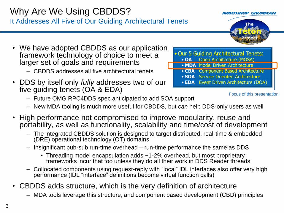
• We have adopted CBDDS as our application framework technology of choice to meet a larger set of goals and requirements
– CBDDS addresses all five architectural tenets
• DDS by itself only fully addresses two of our five guiding tenets (OA & EDA)
– Future OMG RPC4DDS spec anticipated to add SOA support
– New MDA tooling is much more useful for CBDDS, but can help DDS-only users as well
• High performance not compromised to improve modularity, reuse and portability, as well as functionality, scalability and time/cost of development
– The integrated CBDDS solution is designed to target distributed, real-time & embedded (DRE) operational technology (OT) domains
– Insignificant pub-sub run-time overhead – run-time performance the same as DDS
• Threading model encapsulation adds ~1-2% overhead, but most proprietary frameworks incur that too unless they do all their work in DDS Reader threads
– Collocated components using request-reply with “local” IDL interfaces also offer very high performance (IDL “interface” definitions become virtual function calls)
• CBDDS adds structure, which is the very definition of architecture – MDA tools leverage this structure, and component based development (CBD) principles
3
• Our 5 Guiding Architectural Tenets: • OA Open Architecture (MOSA) • MDA Model Driven Architecture • CBA Component Based Architecture • SOA Service Oriented Architecture • EDA Event Driven Architecture (DOA)
Focus of this presentation

CBDDS MDA Tooling Development History
• NGC1 has been helping the OT community develop CBDDS technology since 2008 – Many customer & NGC funded sponsorships of OSS/commercial middleware implementations and MDE tooling
• Early recognition: MDA tooling for DDS in general was lacking for architecture & design – In 2008-2009 time frame, DDS specific tooling mostly limited to run-time debug & integration
• Initial efforts began with the CoSMIC GME-based research tool from Vanderbilt ISIS – CoSMIC already supported CCM and D&C artifact generation, but had no DDS support
– Leveraged expertise of Dr. James Hill at IUPUI and Vanderbilt ISIS to improve it
• Added DDS4CCM, AMI4CCM & improved D&C support to CoSMIC – still available
– Established tool use for CBDDS as a viable, desirable and necessary approach (D&C CDP files are complex)
• Soon looked toward UML-based, commercially supported alternatives – Easier to develop a fully integrated, MDA-driven, soup-to-nuts systems/software engineering approach
• SysML UML profile for systems architecture
• CBDDS UML profile for component-level software architecture supporting a CBD2 process
• Vanilla UML for class-level, intra-component software design & implementation
– Added support for CBDDS architecture/design, rather than just deployment planning (primary CoSMIC strength)
• Began dual development efforts with Zeligsoft (now PrismTech) and Atego in 2009 – Zeligsoft already proficient in CBD for its SDR products, Atego was our sector’s enterprise UML tool vendor
– CoSMIC generated artifacts and research results used as gold standard reference for both efforts
– Today we have two capable commercial products available to support OMG CBDDS and DDS open standards
1NGC: Northrop Grumman Corporation 2CBD: Component Based Development (process) 4
MDA Tools are Available to Support CBD for
CBDDS and Auto-Generation of Critical Artifacts
5
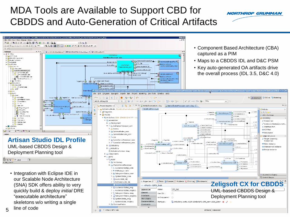
• Component Based Architecture (CBA)
captured as a PIM
• Maps to a CBDDS IDL and D&C PSM
• Key auto-generated OA artifacts drive
the overall process (IDL 3.5, D&C 4.0)
Artisan Studio IDL Profile UML-based CBDDS Design &
Deployment Planning tool
Zeligsoft CX for CBDDS UML-based CBDDS Design &
Deployment Planning tool
• Integration with Eclipse IDE in
our Scalable Node Architecture
(SNA) SDK offers ability to very
quickly build & deploy initial DRE
“executable architecture”
skeletons w/o writing a single
line of code

Component Based Software Lifecycle Process Agile, Iterative Six-Step Process Driven by Standard File Artifacts
6
IDL CDP CDD
• Zeligsoft CX • Artisan Studio • Eclipse
• Zeligsoft CX • Artisan Studio
Design Tool IDE Tool Deployment
Planning Tool
System Software Design &
Component Definition
Component Interface
Design
Component Packaging &
Assembly
Component Deployment, Integration &
Reuse
Component Software Design
Component Implementation
1 2 5 6 4 3
Arc
hitect
ure
&
Syst
em
D
esi
gn
Syst
em
In
tegra
tion,
Test
&
Verifica
tion
SNA CBD Software Lifecycle Process
Key
Artifacts CPP, H SO
• IDE: Integrated Development Environment
• CBD: Component Based Development
• SNA: Scalable Node Architecture
• IDL: Interface Definition Language (OMG)
• CDP: Component Deployment Plan
• CDD: Component Domain Descriptor
Tool-Centric CBD Software Lifecycle Process View
Agile process iterations early & often, incrementally building up from an early executable “skeleton” architecture
IDL 3.5 File
Taxonomy
Supported by
MDA Tools
-
5 Standard File
Types
-
Use of optional
file extensions
enables “smart”
build by an SDK
OMG IDL Defines All CBDDS Elements Components, Connectors, Messages, Interfaces & Basic Def’s
7
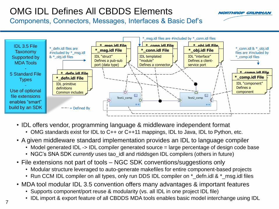
• IDL offers vendor, programming language & middleware independent format • OMG standards exist for IDL to C++ or C++11 mappings, IDL to Java, IDL to Python, etc.
• A given middleware standard implementation provides an IDL to language compiler • Model generated IDL -> IDL compiler generated source = large percentage of design code base
• NGC’s SNA SDK currently uses tao_idl and rtiddsgen IDL compilers (others in future)
• File extensions not part of tools – NGC SDK conventions/suggestions only • Modular structure leveraged to auto-generate makefiles for entire component-based projects
• Run CCM IDL compiler on all types, only run DDS IDL compiler on *_defn.idl & *_msg.idl files
• MDA tool modular IDL 3.5 convention offers many advantages & important features • Supports component/port reuse & modularity (vs. all IDL in one project IDL file)
• IDL import & export feature of all CBDDS MDA tools enables basic model interchange using IDL
*_defn.idl File
IDL primitive definitions Common includes
*_defn.idl File
IDL primitive definitions Common includes
*_comp.idl File
IDL “component” Defines a component
*_comp.idl File
IDL “component” Defines a component
*_conn.idl & *_obj.idl files are #included by *_comp.idl files
*_obj.idl File
IDL “interface” Defines a client- service port
*_obj.idl File
IDL “interface” Defines a client- service port
*_defn.idl files are #included by *_msg.idl & *_obj.idl files
*_msg.idl File
IDL “struct” Defines a pub-sub port (data type)
*_msg.idl File
IDL “struct” Defines a pub-sub port (data type)
= Defined By
*_conn.idl File
IDL “struct” Defines a pub-sub port (data type)
*_conn.idl File
IDL templated “module” Defines a connector
*_msg.idl files are #included by *_conn.idl files

Examples of Modular IDL 3.5 Important for Modularity, Reuse & Tool Interoperability
8
// File: EX_Test2_comp.idl
// Example component definition
// Well-defined, using OMG IDL 3.5
#include <Components.idl>
#include “EX_PubSub_conn.idl“
#include “EX_MyMsg_conn.idl“
#include “EX_ControlService_obj.idl“
#pragma ciao lem “EX_Component_compE.idl"
module EX
{
component Test2_comp
{
attribute string myProp;
uses ControlService_obj ClientRecept;
port PubSub_conn::DDS_Write ExamplePub;
port MyMsg_conn::DDS_Listen MyMsgSub;
};
};
// File: EX_PubSub_conn.idl
// Example module instantiation of one or more connectors
// Well-defined, using OMG IDL 3.5
#include <Components.idl>
#include <ccm_dds.idl>
#include “EX_PubSub_msg.idl“
#pragma ciao lem “EX_PubSub_connE.idl"
module AGSP
{
typedef sequence<PubSub_msg> PubSub_msgSeq;
module CCM_DDS::Typed<PubSub_msg, PubSub_msgSeq> PubSub_conn;
};
// File: EX_ControlService_obj.idl
// Example request-reply service
// Well-defined, using OMG IDL
#include “EX_Common_defn.idl”
#pragma ciao lem
“EX_ControlService_objE.idl“
module EX
{
interface ControlService_obj
{
ReturnStatus changeState(
in SystemState newState);
SystemState getCurrentState();
ReturnStatus setMode(
in SystemMode newMode);
SystemMode getCurrentMode();
boolean setStateTimeout (
inout TimeStruct timer,
in long timeValue);
};
};
// File: EX_PubSub_msg.idl
// Example pub-sub message
// Well-defined, using OMG IDL
#include “EX_Common_defn.idl”
#pragma ndds typesupport
“EX_PubSub_msgSupport.h“
module EX
{
struct PubSub_msg
{
SystemMode modeID;
JobID_t jobID; //@key
StatusEnum status;
ErrorEnum errorVal;
SystemTime startTime;
unsigned long long duration;
short currPicCount;
boolean valid;
}; //@top-level true
};
// File: EX_Common_defn.idl
// Example definitions package
// Well-defined, using OMG IDL
module EX
{
const long TEST_CONSTANT = 9876;
typedef double SystemTime;
enum ReturnStatus {
SUCCESS,
FAILURE
};
typedef string<512> BoundString;
// more...
};
• Modeling & generation of
IDL for definitions & DDS
messages also useful to
DDS-only users
ONE struct/union per file, any/all required
types #included from *_defn.idl file(s)
N types from a single UML package
ONE interface per file, any/all required
types #included from *_defn.idl file(s)
ONE component per file, plus optional home
ONE “connector” module instantiation per file

Model Element to CBDDS Artifact Mappings
9
Model Element that Generates a
File System Artifact Artisan
Studio Icon Zeligsoft CX
Icon
Package (Directory)
IDL Module (keyword)
IDL Component (type, mono impl)
IDL Interface
IDL Connector (pkg stereotype)
IDL Message (msg, sequence)
IDL Definitions
D&C Target Domain (CDD)
D&C Deployment Plan (CDP)
• Each of the model elements in this table creates a corresponding artifact in a source project file system on generation
• Models can contain other types and elements as desired, but only the uniquely stereotyped elements in this table will generate CBDDS artifacts
File
System
IDL
D&C
• File system directory
• Two results: • IDL “module” (namespace) block
inside generated IDL files of children
• Prefix on generated IDL filenames
*_defn.idl File
*_msg.idl File *_conn.idl File
*_obj.idl File
*_comp.idl File
*.cdd File
*.cdp File

Module/Package View CX Project Explorer & Studio Package Browser
10
• Project static architecture view in model used to define and generate project source tree
– Initially populated with modular IDL 3.5 and D&C 4.0 descriptor files
– Developers add business logic classes to initial component executor stubs
• Integrated soup-to-nuts SDK offers architecture, design, eventual coding & implementation, deployment planning, launch & debug in a common tool
– Integrated steps include:
• Define components, connectors & ports
• Create instances & connections in an assembly
• Create a domain & basic deployment plan (including component server process instances as needed for deployment)
• Generate IDL and D&C artifacts
• Auto-gen makefiles and build project
• Compile (IDL & source in one compile)
• Launch executable architecture
• Test & Debug
– Entire process can be completed in just a few minutes for a small set of components
• For initial executable skeleton architecture w/o code added to “your code goes here” callback stubs
Definitions
Package Type
Component
Type
Interface
Type
Message
Type
Connector
Type
Packages
become dirs
on source
project
generation
assemblies
components
ports
Definitions
Package Type
Component
Type
Interface
Type
Message
Type
Connector
Type
Packages
become dirs
on source
project
generation
assemblies
components
ports
Zeligsoft CX for CBDDS Artisan Studio IDL Profile
Component Assembly Hierarchy Example Artisan Studio IDL Profile
11
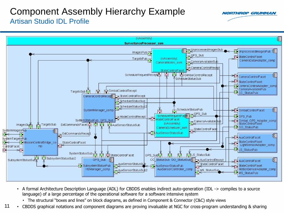
• A formal Architecture Description Language (ADL) for CBDDS enables indirect auto-generation (IDL -> compiles to a source language) of a large percentage of the operational software for a software intensive system
• The structural “boxes and lines” on block diagrams, as defined in Component & Connector (C&C) style views
• CBDDS graphical notations and component diagrams are proving invaluable at NGC for cross-program understanding & sharing
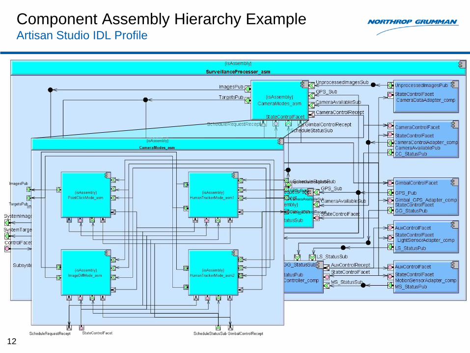
Component Assembly Hierarchy Example Artisan Studio IDL Profile
12

Component Assembly Hierarchy Example Artisan Studio IDL Profile
13

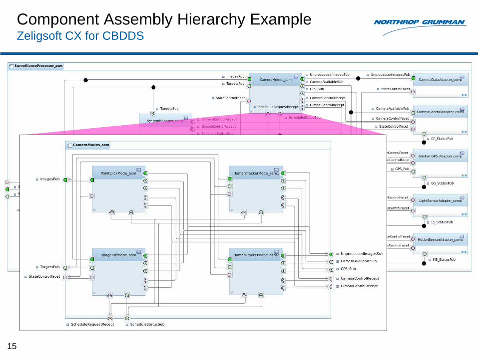
Component Assembly Hierarchy Example Zeligsoft CX for CBDDS
14
• C&C style Component Assembly diagrams offer a “software schematic” view of your run-time structural architecture
• Shows system run-time composition using standard “software parts”
• Similar to hardware schematics connecting standard hardware parts
• Connections drawn in an MDA modeling tool are automatically established during the deployment launch phase by the D&C deployment framework – big time/code savings to developers
Component Assembly Hierarchy Example Zeligsoft CX for CBDDS
15
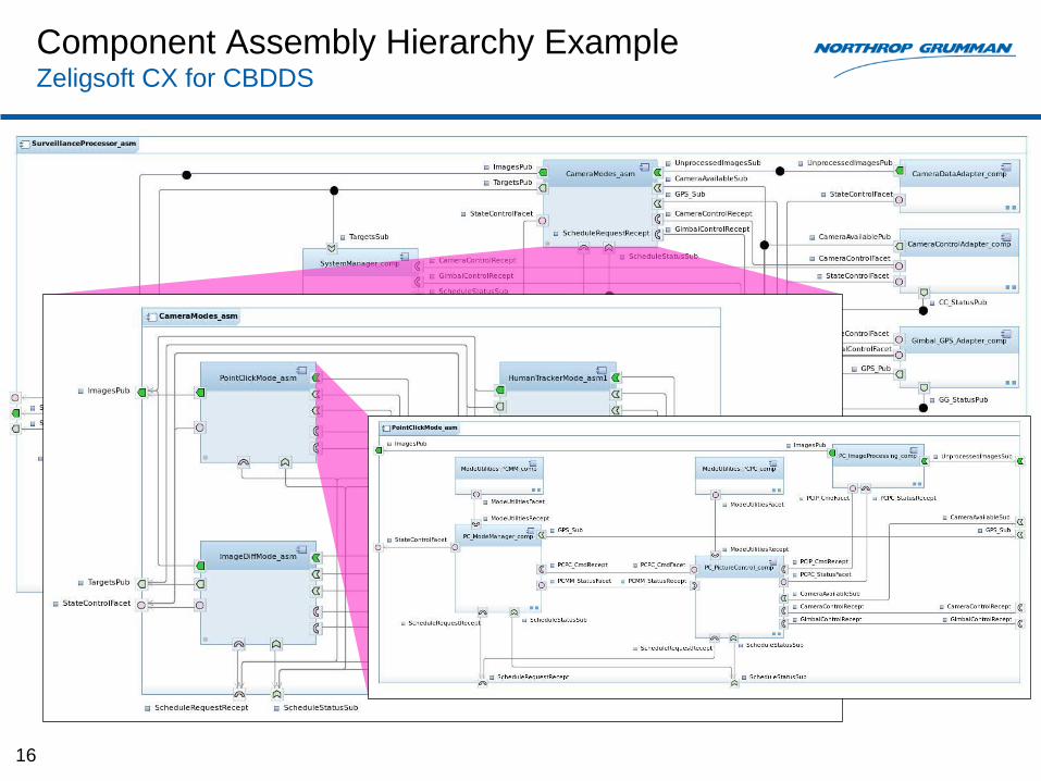
Component Assembly Hierarchy Example Zeligsoft CX for CBDDS
16

Domain Diagram & Deployment Plan Editor Zeligsoft CX for CBDDS
17
• Allocation style Domain & Deployment diagrams capture QoS, config & aspects of system resource utilization for resource allocation and concurrency
• A Deployment “diagram” maps:
• Each component instance to a component server process (+ container)
• Processes to compute nodes (OS instances) defined for a Domain

Domain Diagram & Deployment Plan Editor Artisan Studio IDL Profile
18
• The Deployment Plan editor in both tools allows users to set many configurable parameters post-design, later generated to a D&C CDP deployment plan
• Per-instance user defined component attributes, accessible at run-time
• Connector attributes, including topic names, domain IDs, QoS profiles & content filter expressions & parameters to auto-define content filtered topics
• Component server OS process attributes, including name, process priority, and core affinity for real-time tuning
• Each deployment plan starts with a 1) Domain, 2) Top level assembly (contains component/connector instances & connections), and 3) a set of process instances created for the plan
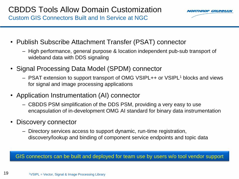
CBDDS Tools Allow Domain Customization Custom GIS Connectors Built and In Service at NGC
• Publish Subscribe Attachment Transfer (PSAT) connector
– High performance, general purpose & location independent pub-sub transport of
wideband data with DDS signaling
• Signal Processing Data Model (SPDM) connector
– PSAT extension to support transport of OMG VSIPL++ or VSIPL1 blocks and views
for signal and image processing applications
• Application Instrumentation (AI) connector
– CBDDS PSM simplification of the DDS PSM, providing a very easy to use
encapsulation of in-development OMG AI standard for binary data instrumentation
• Discovery connector
– Directory services access to support dynamic, run-time registration,
discovery/lookup and binding of component service endpoints and topic data
19 1VSIPL = Vector, Signal & Image Processing Library
GIS connectors can be built and deployed for team use by users w/o tool vendor support

Support for User-Defined Connectors Example Showing Basic and Extended Port Types & Connectors
20
Service (Facet)
Client (Receptacle)
Sync or Async (AMI4CCM)
Basic Port Types Extended Port Types
DDS_Write, DDS_Update
DDS_Listen, DDS_Read,
DDS_StateListen, DDS_Get
PSAT_Write
PSAT_Listen
SPDM PSAT_Base::PSAT_Write
SPDM PSAT_Base::PSAT_Listen Discover (Data or Services)
AI_Save
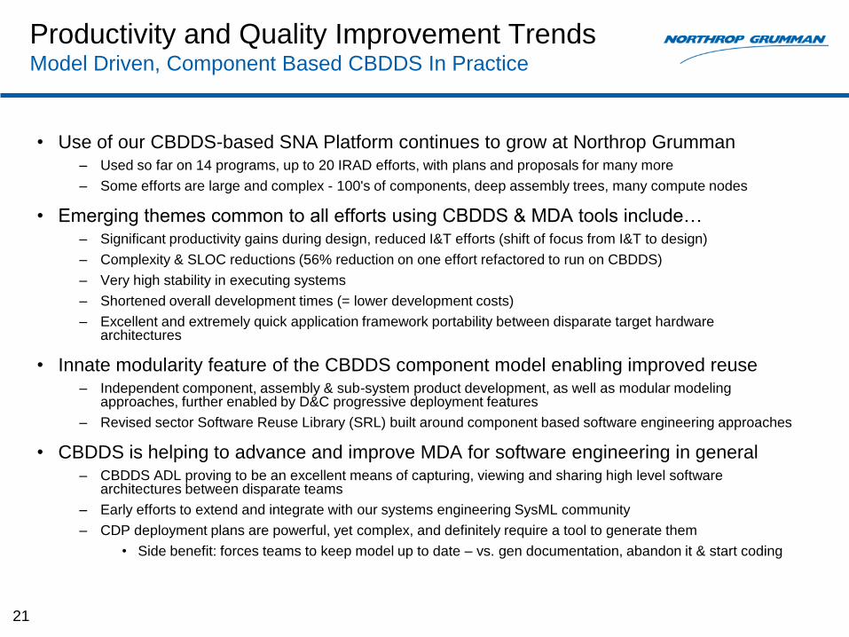
Productivity and Quality Improvement Trends Model Driven, Component Based CBDDS In Practice
• Use of our CBDDS-based SNA Platform continues to grow at Northrop Grumman – Used so far on 14 programs, up to 20 IRAD efforts, with plans and proposals for many more
– Some efforts are large and complex - 100's of components, deep assembly trees, many compute nodes
• Emerging themes common to all efforts using CBDDS & MDA tools include… – Significant productivity gains during design, reduced I&T efforts (shift of focus from I&T to design)
– Complexity & SLOC reductions (56% reduction on one effort refactored to run on CBDDS)
– Very high stability in executing systems
– Shortened overall development times (= lower development costs)
– Excellent and extremely quick application framework portability between disparate target hardware architectures
• Innate modularity feature of the CBDDS component model enabling improved reuse – Independent component, assembly & sub-system product development, as well as modular modeling
approaches, further enabled by D&C progressive deployment features
– Revised sector Software Reuse Library (SRL) built around component based software engineering approaches
• CBDDS is helping to advance and improve MDA for software engineering in general – CBDDS ADL proving to be an excellent means of capturing, viewing and sharing high level software
architectures between disparate teams
– Early efforts to extend and integrate with our systems engineering SysML community
– CDP deployment plans are powerful, yet complex, and definitely require a tool to generate them
• Side benefit: forces teams to keep model up to date – vs. gen documentation, abandon it & start coding
21

Where is CBDDS Going in the Future?
• Unified Component Model (UCM) – Future alternative to the LwCCM component model used today for CBDDS
– Transition from LwCCM to UCM anticipated to be straightforward
• Very similar in approach, common foundational technologies, IDL centric
• Future UCM-based CBDDS framework to offer the following features: – Vendor, programming language & middleware agnostic APIs
• Current LwCCM dependency on CORBA removed
• Middleware products like DDS, CORBA, others… - become selectable options
– Same fundamental GIS connector framework used today by LwCCM
• All middleware options abstracted into connectors – no native middleware
• Enables domain customization and extension
– All-DDS transport option for both pub-sub and request-reply pattern oriented port APIs
– Lighter weight, smaller memory/storage footprint, higher performance
• Impact on CBDDS MDA tooling – Minimal - most model content & tooling capabilities are already either platform
independent (PIM), or IDL specific (high level, middleware agnostic PSM)
– Add support for extended ports for request-reply as well as pub-sub patterns
– Updates to OMG D&C CDP descriptor file generation algorithms (backend generator)
22


Backup Slides
Abstract
A Component Based DDS (CBDDS) application framework encompasses an integrated suite of seven OMG open
standard technologies, including CCM, DDS, DDS4CCM, AMI4CCM, CORBA, IDL and D&C (DEPL). Two relatively
new UML-based commercial tools are now generally available from vendors Atego and Zeligsoft to support the full
CBDDS technology suite. These tools offer significant productivity gains for development of distributed, real-time,
embedded (DRE) component-based applications that leverage DDS, particularly for large, complex systems. Their
CBDDS UML profiles and workflows provide support for independent component-oriented engineering design and
deployment planning methodologies, and they generate IDL 3.5 and D&C 4.0 compliant file artifacts to greatly simplify
the construction of CBDDS deployments. Supplemented by future DDS QoS file generation per a standardized
UML4DDS profile, hierarchical CBDDS component & connector (C&C) style dynamic architecture views, plus DDS-
annotated IDL file output artifacts, there is also potential value for software intensive systems that leverage a simpler,
less-structured, DDS-only messaging framework.
This presentation will provide an overview of the comprehensive features and capabilities available in the Artisan Studio
IDL Profile and Zeligsoft CX for CBDDS model-driven tool suites, citing real-world examples, custom DDS4CCM
compliant “connector” extensions, and Model Driven Architecture (MDA) lessons learned at Northrop Grumman over
the past 3 years through wide application of this technology. We will cover the agile, model-based, component-based
development (CBD) process we have established, driven primarily by standards-based file artifacts that enable use of
any current or future tool at the various lifecycle stages of CBD development. Finally, we will present the productivity
gains we are seeing as a result of building complex DRE systems at the higher, more structured application framework
layer of abstraction offered by CBDDS, and the numerous advantages offered by CBDDS over DDS in terms of MDA
tooling, enforced modularity, portability, more efficient development, complexity reduction and scalability through
threading model encapsulation, and improved component level software reuse.