model-based thermal design for smaller,
TRANSCRIPT

1
With higher performance demands than ever, various electronic devices, such as mobile phones, cameras, and ECUs mounted on automobiles, are becoming more integrated with sophisticated electronics. At the same time, electronic devices are required to be further miniaturized and have to be densified, which makes the heat problem in electronic devices more serious.
If the thermal design is neglected, the temperature of the equipment can rise to dangerous levels, causing not only malfunction and shorter life span, but also increasing the risk of accidents such as burns to the user.
Generally, thermal design has been handled individually by mechanical designers and electrical designers. In addition, verification of system performance is often done towards later stages of design using physical devices. If problems arise, countermeasures have to be considered within a limited range of design freedom because physical production is already underway. However, with the densification of electronic devices in recent years, it is becoming difficult to deal with
post-process countermeasures, and it is becoming more important to implement thermal design of the entire system much earlier in the design process.
The Thermal Network Method and 1D CAESimulation using a computer is very effective in evaluating the design at the concept level, which is the absence of detailed shape information such as CAD or the physical machine. On the other hand, the Thermal
Model-Based Thermal Design for Smaller, Efficient Electronic Devices
Thermal Design Techniques for Higher Integration and Downsizing of Electronic Devices
Figure 1: With the shrinking sizes of sophisticated electronics, neglect of thermal design can have serious consequences.

2
Network Method (TNM) is an effective technique for expressing the heat phenomenon with features on a computer1 2 3.
In addition, 1D CAE (or, 1D simulation) software such as MapleSimTM [4] can express the entire system with the necessary degree of detail, and is suitable for use at the initial stages of design. This technique is compatible with the TNM, and simulation can be executed after modeling based on that concept. This whitepaper outlines the TNM and demonstrates the advantages of using a 1D CAE tool for this method.
Shown in Figure 2 is an example of an object with its associated thermal network, in which a heat-generating component is mounted on a substrate whose temperature is kept constant. In this TNM, the voltage in the electronic circuit is modeled as temperature and the current is modeled as heat quantity. The amount of heat generated by the heat-generating component is represented by a current source, and the heat capacity of the heat-generating component is represented by a capacitor. The substrate expresses a constant temperature rise from the reference temperature with a voltage source. Also, the heat-generating component and the substrate are in close contact with each other due to thermal conduction (thermal resistance).
In Figure 3, the previous thermal network is represented with MapleSim, the 1D CAE modeling and simulation tool from Maplesoft. The Modelica Standard Library makes it possible to create an intuitive model, expressed as a thermal problem rather than an electronic circuit representation. This library also supports convection and radiation. Using a 1D CAE modeling approach offers many capabilities for thermal design, but projects can become highly complicated and difficult for non-expert users. Therefore, combining the Thermal Network Method and MapleSim can provide an easier approach to thermal design that is more accessible to designers.
Thermal Analysis of an Electronic DeviceIn this section, the thermal analysis of electronic devices using Thermal Network Method and 1D CAE tool are explored. Figure 4 shows the heat transfer path in the electronic board and the case enclosure, while Figure 5 shows the thermal network. Red dots indicate contact points and represent the positions of the heat capacity for calculating temperature.
Heat generated, in part due to the electric power consumed, is transmitted to the part surface, the substrate, and the heat transfer sheet by heat conduction, and then further flows to the case.
Figure 2: A simple example using a thermal network approach.
Figure 3: A thermal network method represented using a 1D CAE tool.

3
Thereafter, it is transferred by conduction inside the case, and is dissipated from the case surface to the surroundings by convection and radiation. Additionally, the heat of the parts and the substrate are transmitted to the case also by convection through the internal air. It is important that radiation heat from parts to the case is also taken into consideration.
When modeling with a 1D CAE tool based on the TNM, placement of heat-generating parts and temperature distribution on the substrate can be problems. Since the thermal network representation in Figure 5 is simple, when modeling the physical device it is necessary to roughly divide the substrate and the case so that the temperature distribution can be analyzed.
Figure 6 is a model created by MapleSim, using components from the Modelica Standard Library. As described above, the substrate is divided into 16, and the case is divided for each surface, in order to confirm the temperature distribution. Therefore, it is a fairly detailed model as compared with the thermal network shown in Figure 5. In this model, it is possible to represent the rough placement of heat-generating parts, and fixing points between the substrate and case, depending on where the heat-generating parts are connected in the divided substrate.
Figure 7 and Figure 8 show the analysis results using the model found in Figure 6. As a whole, the device is in a steady state at about 3000 seconds, with the heat-generating part B rising to the highest temperature of 52°C (326 K). If the operating temperature is intended to be 50°C, there is likely a problem in the thermal design. Additionally, looking at the steady state case temperature, only the lower surface of the case experiences a large temperature rise due to the heat transmitted through the substrate and the heat
Figure 6: The MapleSim model of the circuit board example, which offers a higher fidelity approach than the previous thermal network.
Figure 4: Heat transfer path of an electronic circuit board.
Figure 5: The electronic circuit board from Figure 4, modeled as a thermal network.

4
transfer sheet. If the case material, while often plastic, can be changed to other heat-conductive materials and the temperature distribution of the case can be made uniform, then it can be expected to lower the temperature of the heat-generating component.
Two countermeasures were examined and verified against this design task. One is to change the case material as mentioned and the other is to change from natural air cooling to forced air cooling by fan. The material change is expressed and analyzed by the physical property value, and the effect of the fan is done by changing the heat transfer coefficient of the convection. The result is shown in Figure 9. These
measures succeed in suppressing the temperature of the heat-generating component B to 50°C or lower by changing the material as expected. On the other hand, forced air cooling by fan is also effective, but may pose other considerations to the design, such as cost or lifespan issues.
As demonstrated here, it can be very effective to validate the design concepts by combining the TNM and a 1D CAE tool such as MapleSim. Moreover, in this example, it is possible to calculate the analysis of 5000 seconds in less than a minute, using only a modern personal computer. Using this efficiency, parameter studies with various combinations can be performed at high speed.
Thermal Modeling Challenges and SolutionsAs shown in the previous section, combining the TNM and a 1D CAE tool can be an effective approach for solving thermal design problems. However, the modeling process itself can pose limitations. As shown in Figure 6, when the substrate is divided into 16 sections to calculate the temperature distribution, arranging the necessary components can be burdensome.
Figure 7: The time-dependent heating of various locations of the electronic circuit board.
Figure 8: The steady-state temperatures of the electronic circuit board.
Figure 9: Thermal analysis of the circuit board with different cooling measures taken.
5
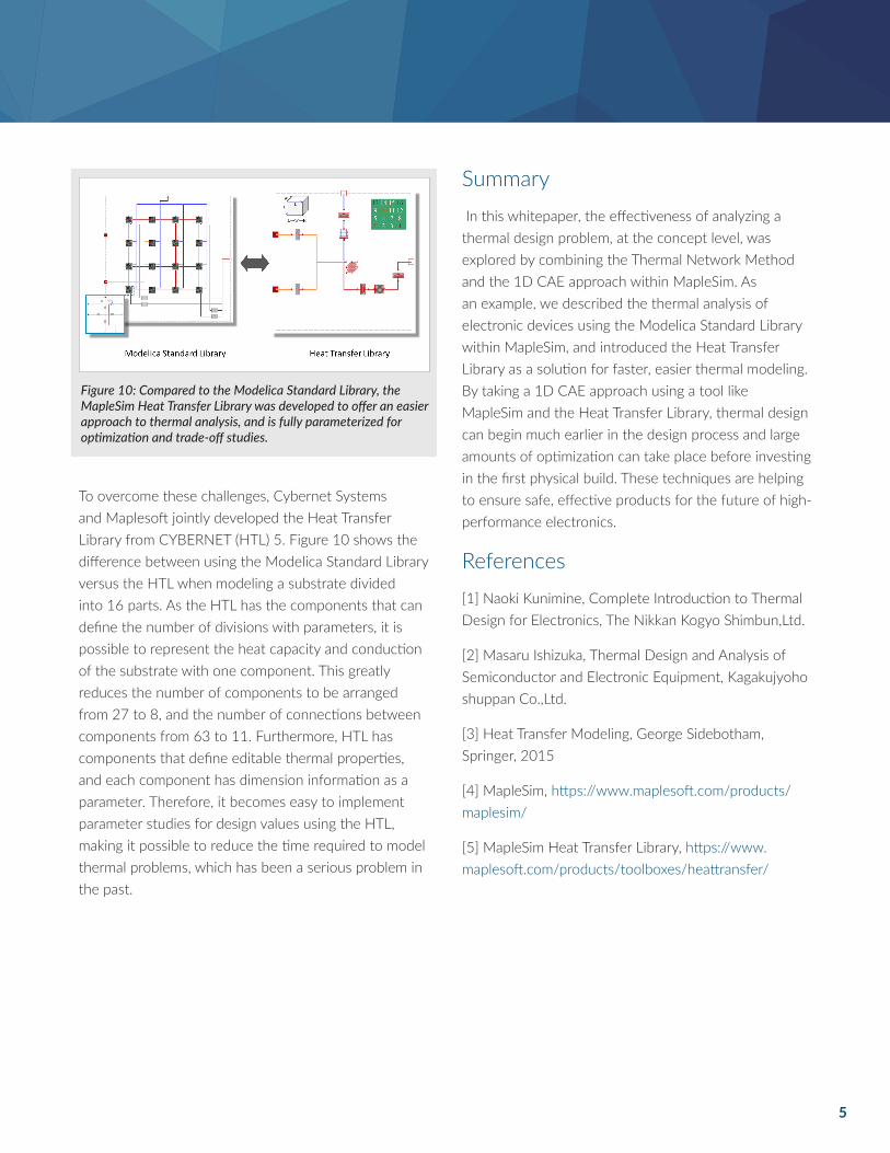
To overcome these challenges, Cybernet Systems and Maplesoft jointly developed the Heat Transfer Library from CYBERNET (HTL) 5. Figure 10 shows the difference between using the Modelica Standard Library versus the HTL when modeling a substrate divided into 16 parts. As the HTL has the components that can define the number of divisions with parameters, it is possible to represent the heat capacity and conduction of the substrate with one component. This greatly reduces the number of components to be arranged from 27 to 8, and the number of connections between components from 63 to 11. Furthermore, HTL has components that define editable thermal properties, and each component has dimension information as a parameter. Therefore, it becomes easy to implement parameter studies for design values using the HTL, making it possible to reduce the time required to model thermal problems, which has been a serious problem in the past.
Summary In this whitepaper, the effectiveness of analyzing a thermal design problem, at the concept level, was explored by combining the Thermal Network Method and the 1D CAE approach within MapleSim. As an example, we described the thermal analysis of electronic devices using the Modelica Standard Library within MapleSim, and introduced the Heat Transfer Library as a solution for faster, easier thermal modeling. By taking a 1D CAE approach using a tool like MapleSim and the Heat Transfer Library, thermal design can begin much earlier in the design process and large amounts of optimization can take place before investing in the first physical build. These techniques are helping to ensure safe, effective products for the future of high-performance electronics.
References[1] Naoki Kunimine, Complete Introduction to Thermal Design for Electronics, The Nikkan Kogyo Shimbun,Ltd.
[2] Masaru Ishizuka, Thermal Design and Analysis of Semiconductor and Electronic Equipment, Kagakujyoho shuppan Co.,Ltd.
[3] Heat Transfer Modeling, George Sidebotham, Springer, 2015
[4] MapleSim, https://www.maplesoft.com/products/maplesim/
[5] MapleSim Heat Transfer Library, https://www.maplesoft.com/products/toolboxes/heattransfer/
Figure 10: Compared to the Modelica Standard Library, the MapleSim Heat Transfer Library was developed to offer an easier approach to thermal analysis, and is fully parameterized for optimization and trade-off studies.

6
www.maplesoft.com | [email protected] Toll-free: (US & Canada) 1-800-267-6583 | Direct:1-519-747-2373 © Maplesoft, a division of Waterloo Maple Inc., 2018. Maplesoft, Maple, and MapleSim are trademarks of Waterloo Maple Inc. All other trademarks are the property of their respective owners.