model based cloud platform upperware deliverable d2.1 · d2.1.3 camel documentation page 1 of 82...
TRANSCRIPT
D2.1.3CAMELDocumentation Page1of82
PaaSage
ModelBasedCloudPlatformUpperware
DeliverableD2.1.3
CAMELDocumentation
Version:1.1
PAA AGE

D2.1.3CAMELDocumentation Page2of82
D2.1.3Name,titleandorganisationofthescientificrepresentativeoftheproject'scoordinator:
MrPhilippeRohouTel:+33492385306Fax:+33492387822E-mail:[email protected]:http://www.paasage.eu
Project
Grant Agreement number 317715
Project acronym: PaaSage
Project title: Model Based Cloud Platform Upperware
Funding Scheme: Integrated Project
Date of latest version of Annex I against which the assessment will be made:
30th September 2015
Document
Period covered:
Deliverable number: D2.1.3
Deliverable title CAMEL Documentation
Contractual Date of Delivery: 301h September 2015 (M36)
Actual Date of Delivery: 16th October 2015
Editor (s): Alessandro Rossini
Author (s): Alessandro Rossini, Kiriakos Kritikos, Nikolay Nikolov, Jörg Domaschka, Frank Griesinger, Daniel Seybold, Daniel Romero
Reviewer (s): Jörg Domaschka, Achilleas Achilleos
Participant(s):
Work package no.: 2
Work package title: Languages
Work package leader: Alessandro Rossini
Distribution:
Version/Revision: 1.1
Draft/Final: Final
Total number of pages (including cover): 82

D2.1.3CAMELDocumentation Page3of82
DISCLAIMER
ThisdocumentcontainsdescriptionofthePaaSageprojectworkandfindings.
Theauthorsofthisdocumenthavetakenanyavailablemeasureinorderforitscontenttobeaccurate,consistentandlawful. However, neither the project consortium as a whole nor the individual partners that implicitly or explicitlyparticipatedinthecreationandpublicationofthisdocumentholdanyresponsibilityforactionsthatmightoccurasaresultofusingitscontent.
ThispublicationhasbeenproducedwiththeassistanceoftheEuropeanUnion.ThecontentofthispublicationisthesoleresponsibilityofthePaaSageconsortiumandcaninnowaybetakentoreflecttheviewsoftheEuropeanUnion.
TheEuropeanUnion isestablished inaccordancewith theTreatyonEuropeanUnion(Maastricht).Therearecurrently28MemberStatesoftheUnion.ItisbasedontheEuropeanCommunities and the member states cooperation in thefieldsofCommonForeignandSecurityPolicyandJusticeandHome Affairs. The five main institutions of the EuropeanUnionaretheEuropeanParliament,theCouncilofMinisters,theEuropeanCommission,theCourtofJusticeandtheCourtofAuditors.(http://europa.eu)
PaaSageisaprojectfundedinpartbytheEuropeanUnion.
Executive SummaryCloud computing provides ubiquitous networked access to a shared and virtual-ised pool of computing capabilities that can be provisioned with minimal man-agement e↵ort [25]. Cloud applications are deployed on cloud infrastructuresand delivered as services. The PaaSage project aims to facilitate the model-ling and execution of cloud applications by leveraging model-driven engineering(MDE) and by exploiting multiple cloud infrastructures. Models enable the ab-straction from the implementation details of heterogeneous cloud services, whilemodel transformations facilitate the automatic generation of the source code thatexploits these services. The Cloud Application Modelling and Execution Lan-guage (CAMEL) is the core modelling and execution language developed inthe PaaSage project and enables the specification of multiple aspects of cross-cloud applications (i.e., applications deployed across multiple private, public,or hybrid cloud infrastructures). By exploiting models at both design- and run-time, and by allowing both direct and programmatic manipulation of models,CAMEL enables the management of self-adaptive cross-cloud applications (i.e.,cross-cloud applications that autonomously adapt to changes in the environment,requirements, and usage). In this document, we describe the design and imple-mentation of CAMEL. Moreover, we provide a real-world running example toillustrate how to specify models in a concrete textual syntax and how to program-matically manipulate and persist them through Java APIs. Finally, we describethe abstract syntax of the language.
D2.1.3 CAMEL Documentation Page 4 of 82

Contents
Contents 5
1 Introduction 7
2 CAMEL and the Self-Adaptation Workflow 8
3 Technologies 11
4 Installation and Usage of CAMEL Textual Editor 124.1 Installation—Users . . . . . . . . . . . . . . . . . . . . . . . . 134.2 Installation—Developers . . . . . . . . . . . . . . . . . . . . . 134.3 Usage . . . . . . . . . . . . . . . . . . . . . . . . . . . . . . . 14
5 CAMEL Design and Syntax 14
6 Deployment 176.1 Interplay with Executionware . . . . . . . . . . . . . . . . . . . 21
6.1.1 Life Cycle Scripts for Unix-based Applications . . . . . 216.1.2 Life Cycle Scripts for Windows-based Applications . . . 24
7 Requirements 26
8 Metrics and Scalability Rules 288.1 Interplay with Executionware . . . . . . . . . . . . . . . . . . . 32
9 Organisations 32
10 Providers 33
11 Security 36
12 Execution 38
13 Locations 40
14 Units 40
15 Types 41
16 Java APIs and CDO 43
D2.1.3 CAMEL Documentation Page 5 of 82

17 Related Work 4717.1 Tools . . . . . . . . . . . . . . . . . . . . . . . . . . . . . . . . 4817.2 Languages . . . . . . . . . . . . . . . . . . . . . . . . . . . . . 4817.3 Comparison . . . . . . . . . . . . . . . . . . . . . . . . . . . . 4917.4 Analysis . . . . . . . . . . . . . . . . . . . . . . . . . . . . . . 51
18 Conclusion and Future Work 53
References 54
A Abstract Syntax 58A.1 Deployment . . . . . . . . . . . . . . . . . . . . . . . . . . . . 59A.2 Requirements . . . . . . . . . . . . . . . . . . . . . . . . . . . 61
A.2.1 Hardware, OS & Image and Provider Requirements . . . 62A.2.2 Service Level Objectives and Optimisation Requirements 63A.2.3 Scale Requirements . . . . . . . . . . . . . . . . . . . . 64A.2.4 Security Requirements . . . . . . . . . . . . . . . . . . 64
A.3 Metrics and Scalability Rules . . . . . . . . . . . . . . . . . . . 65A.3.1 Metrics, Properties, Windows, and Schedule . . . . . . . 65A.3.2 Conditions and Contexts . . . . . . . . . . . . . . . . . 69A.3.3 Scalability Rules . . . . . . . . . . . . . . . . . . . . . 71A.3.4 Actions . . . . . . . . . . . . . . . . . . . . . . . . . . 71A.3.5 Events . . . . . . . . . . . . . . . . . . . . . . . . . . . 72
A.4 Organisations . . . . . . . . . . . . . . . . . . . . . . . . . . . 74A.5 Providers . . . . . . . . . . . . . . . . . . . . . . . . . . . . . 75A.6 Security . . . . . . . . . . . . . . . . . . . . . . . . . . . . . . 77A.7 Execution . . . . . . . . . . . . . . . . . . . . . . . . . . . . . 78A.8 Locations . . . . . . . . . . . . . . . . . . . . . . . . . . . . . 79A.9 Units . . . . . . . . . . . . . . . . . . . . . . . . . . . . . . . . 80A.10 Types . . . . . . . . . . . . . . . . . . . . . . . . . . . . . . . 81
D2.1.3 CAMEL Documentation Page 6 of 82

1 IntroductionMDE is a branch of software engineering that aims to improve the productivity,quality, and cost-e↵ectiveness of software development by shifting the paradigmfrom code-centric to model-centric. MDE promotes the use of models and modeltransformations as the primary assets in software development, where they areused to specify, simulate, generate, and manage software systems. This approachis particularly relevant when it comes to the modelling and execution of cross-cloud applications (i.e., applications deployed across multiple private, public, orhybrid cloud infrastructures). This solution allows to exploit the peculiarities ofeach cloud service and hence to optimise the performance, availability, and costof the applications.
Models can be specified using general-purpose languages like the UnifiedModeling Language (UML) [29]. However, to fully unfold the potential ofMDE, models are frequently specified using domain-specific languages (DSLs),which are tailored to a specific domain of concern. The PaaSage1 project exploitsthe latter approach and provides an integrated platform to support the modellingand execution of cross-cloud applications. To achieve this goal, PaaSage de-veloped the Cloud Application Modelling and Execution Language (CAMEL).This DSL allows to specify multiple aspects of cross-cloud applications, suchas provisioning, deployment, service level, monitoring, scalability, providers,organisations, users, roles, security, and execution.
CAMEL supports the models@run-time [5] approach, which provides an ab-stract representation of the underlying running system, whereby a modificationto the model is enacted on-demand in the system, and a change in the system isautomatically reflected in the model.
Reasoning engine
Models@run-time
(1) (2)
Targetmodel
Diff (3)
Adaptationengine
(4)(4)
Currentmodel
Runningsystem
Figure 1: Models@run-time architecture
1http://www.paasage.eu
D2.1.3 CAMEL Documentation Page 7 of 82

Fig. 1 depicts the architecture of models@run-time. A reasoning enginereads the current model (step 1) and produces a target model (step 2). Then,the run-time environment computes the di↵erence between the current modeland the target one (step 3). Finally, the adaptation engine enacts the adaptationby modifying only the parts of the cross-cloud application necessary to accountfor the di↵erence and the target model becomes the current model (step 4).
CAMEL was designed and implemented to allow the design-time specific-ation of models by users as well as their run-time manipulation by reasoners.By exploiting models at both design- and run-time, and by allowing both dir-ect and programmatic manipulation of models, CAMEL enables the manage-ment of self-adaptive cross-cloud applications (i.e., cross-cloud applications thatautonomously adapt to changes in the environment, requirements, and usage).This represents the main motivation for our research and contribution of ourwork, since, to the best of our knowledge, no other integrated language in the lit-erature supports the management of self-adaptive cross-cloud applications (seeSection 17).
Structure of the document: The remainder of the document is organisedas follows. Section 2 describes the role of CAMEL models in a self-adaptationworkflow. Section 3 presents some technologies used to design and implementCAMEL. Section 4 provide instructions for installing and using the CAMELTextual Editor. Sections 5–15 present the various packages of the CAMELmetamodel along with corresponding sample models in concrete syntax. Sec-tion 16 exemplifies the usage of Java APIs to programmatically manipulate andpersist models. Section 17 compares the proposed approach with related work,while Section 18 draws conclusions and outlines plans for future work. Finally,Appendix A presents the abstract syntax of CAMEL.
2 CAMEL and the Self-Adaptation WorkflowThe components managing the life cycle of cross-cloud applications are in-tegrated by leveraging CAMEL models. These models are progressively re-fined throughout the modelling, deployment, and execution phases of a self-adaptation workflow based on the models@run-time approach, as proposed inPaaSage [35].
Figure 2 shows the self-adaptation workflow. The white trapezes representthe activities performed by the user. The white rectangles represent the processesexecuted by the PaaSage platform. The coloured shapes represent the modellingartefacts, whereby the blue ones pertain to the modelling phase, the red ones tothe deployment phase, and the green ones to the execution phase.
D2.1.3 CAMEL Documentation Page 8 of 82

Provisioninganddeploymentmodelling
Qualityofservice
modelling
Provisioninganddeploymentrequirements
Service-levelobjectives Scalabilityrules
Organisationmodelling
Providermodelling
Organisationmodels Providermodels
CAMELCloudprovider-
independentmodelProfiler
Constraintproblem Reasoner
CAMELCloudprovider-specificmodel
Adapter
DeploymentplansExecutionwareInfrastructures
Monitoringdata
Modellingphase
Deploymentphase
Executionphase
Figure 2: CAMEL models in the self-adaptation workflow
In the remainder of the document, we adopt the Scalarm2 [23] use case asa real-world running example to illustrate how to specify multiple aspects ofcloud applications in CAMEL, and how these specifications facilitate the de-ployment of cloud applications across multiple clouds and their self-adaptationto changes in the environment, requirements, and usage. Scalarm is a massivelyself-scalable platform for data farming. Data farming experiments utilise high-performance and high-throughput computing to generate large amounts of datavia simulations. These data are analysed to obtain new insights into the studiedphenomena. The architecture of Scalarm is based on the principles of service-oriented architecture (SOA) and consists of the following services:
• Experiment Manager provides a graphical user interface to coordinate theexecution of data farming experiments.
• Simulation Manager provides a wrapper to execute the simulations onmultiple computational infrastructures.
As data farming experiments are often executed on a large amount of com-putational infrastructures and across multiple data centres, the Scalarm use caseis particularly suitable to illustrate the features of CAMEL.
Modelling phase. The users design a cloud provider-independent model (CPIM),which specifies the deployment of a cross-cloud application along with its re-
2http://www.scalarm.com/
D2.1.3 CAMEL Documentation Page 9 of 82

quirements and objectives (e.g., on virtual hardware, location, and service level)in a cloud provider-independent way.
Figure 3(a) shows the CPIM of Scalarm in graphical syntax. It consists of anExperiment Manager (represented by ExpMan) hosted on a GNU/Linux virtualmachine (represented by Linux). Moreover, the Experiment Manager communic-ates with a Simulation Manager (represented by SimMan) hosted on a GNU/Linuxvirtual machine in a data centre in Norway. Finally, the Experiment Manager hasa service-level objective specifying that the response time must be below 100 ms.
AmazonEC2[location =EU]
SINTEF[location=NO][location:NO]
ExpMan [resp. time< 100 ms]
Linux
SimMan
Linux
expMan1
ubuntu1
simMan1
centos1
simMan2
centos2
CPIM CPSM
(a) (b)
Types
ExpMan
SimMan
Linux
Figure 3: Sample CAMEL models: (a) CPIM; (b) CPSM
Deployment phase. The Profiler component consumes the CPIM, matchesthis model with the profile of cloud providers, and produces a constraint prob-lem. The Reasoner component solves the constraint problem (if possible) andproduces a cloud provider-specific model (CPSM), which specifies the deploy-ment of a cross-cloud application along with its requirements and objectives in acloud provider-specific way. The Adapter component consumes the CPSM andproduces deployment plans, which specify the platform-specific details of thedeployment.
For instance, the Profiler could match the CPIM of Scalarm with the pro-file of cloud providers, identify Amazon EC2, Google Compute Engine, andAzure as the three cloud providers satisfying the virtual hardware requirementsand service-level objectives of the Experiment Manager (response time below100 ms). Moreover, the Profiler could identify SINTEF3 and EVRY4 as the twocloud providers satisfying the virtual hardware and location requirements of theSimulation Manager (data centre in Norway), and produce a corresponding con-straint problem. Then, the Reasoner could rank Amazon and SINTEF as thebest cloud providers to satisfy these requirements and produce a correspondingCPSM.
3https://www.sintef.no/en/4https://www.cloudservices.no/
D2.1.3 CAMEL Documentation Page 10 of 82

Figure 3(b) shows the CPSM in graphical syntax. It consists of an Experi-ment Manager instance, which is hosted on a Ubuntu 14.04 instance at AmazonEC2 in the EU. Moreover, the Experiment Manager instance communicates withtwo Simulation Manager instances, which are hosted on two CentOS 7 virtualmachine instances at SINTEF in Norway.
Execution phase. The Executionware consumes the deployment plans andenacts the deployment of the application components on suitable cloud infra-structures. The PaaSage platform records monitoring data about the applicationexecution from the Executionware, which allows the Reasoner to continuouslyrevise the solution to the constraint problem to better exploit the cloud infra-structures.
3 TechnologiesIn order to design and implement CAMEL, we adopted the Eclipse ModelingFramework (EMF)5 along with Object Constraint Language (OCL) [28], Xtext6,and Connected Data Objects (CDO).7 In the following, we outline these tech-nologies and describe how they facilitate the implementation of the PaaSageplatform described in Section 2.
Eclipse Modeling Framework (EMF). In MDE, the abstract syntax of a DSLis typically defined by its metamodel, which describes the set of concepts, theirattributes, and their relations, as well as the rules for combining these conceptsto specify valid models conforming to this metamodel [29]. EMF is a model-ling framework that facilitates defining DSLs. It provides the Ecore metamodel,which is an Ecore model that conforms to itself (i.e., it is reflexive). The CAMELmetamodel is an Ecore model that conforms to the Ecore metamodel.
EMF allows to generate a Java class hierarchy representation of a metamodel.The Java representation provides a set of APIs that allows the programmaticmanipulation of models.
Object Constraint Language (OCL). EMF enables to check the cardinalityconstraints on properties and to validate models against their metamodels. How-ever, it lacks the expressiveness required to capture all of the semantics of the do-main. OCL is a declarative language for specifying expressions on metamodels
5https://www.eclipse.org/modeling/emf/6https://eclipse.org/Xtext/7https://www.eclipse.org/cdo/
D2.1.3 CAMEL Documentation Page 11 of 82

that are evaluated on models conforming to these metamodels. Eclipse OCL8 isa tool-supported implementation of OCL that integrates with EMF. The CAMELmetamodel is annotated with OCL expressions to capture part of the semanticsof cross-cloud applications and to guarantee the consistency, correctness, andintegrity of CAMEL models at both design-time and run-time.
Xtext. In MDE, the concrete syntax describes the textual or graphical notationthat renders the concepts, attributes, and relations in the abstract syntax. Theconcrete syntax may vary depending on the domain, e.g., a DSL could providea textual notation as well as a graphical notation along with the correspondingserialisation in XML Metadata Interchange (XMI) [30]. Xtext is a languagedevelopment framework that is based on- and integrates with EMF. It facilitatesthe implementation of Eclipse-based IDEs providing features, such as syntaxhighlighting, code completion, code formatting, static analysis, and serialisation.The concrete syntax of CAMEL is a textual syntax defined as an Xtext grammar.The textual syntax was preferred over the graphical syntax by the early adoptersof CAMEL.
Connected Data Objects (CDO). CDO is semi-automated persistence frame-work that works natively with Ecore models and their instances. It providesa model repository where clients can persist, share, and query their models.It provides features that satisfy the design-time and run-time requirements ofthe self-adaptation workflow (see Section 2), such as abstraction from databasemanagement systems (DBMSs), validation, transactional processing, optimisticversioning [38], automatic notification, auditing, and role-based security [21].
Thanks to the combination of EMF, Eclipse OCL, and Xtext, we realised theCAMEL Textual Editor, which allows users not only to specify CAMEL modelsbut also to validate them. Moreover, thanks to these technologies and CDO,we realised the models@run-time approach, which allows multiple reasoners toprogressively refine CAMEL models throughout the various phases of the self-adaptation workflow (see Section 2).
4 Installation and Usage of CAMEL TextualEditorIn this section, we provide instructions for installing and using the CAMEL Tex-tual Editor. These steps have been tested with the latest version of Eclipse, which
8http://wiki.eclipse.org/OCL
D2.1.3 CAMEL Documentation Page 12 of 82
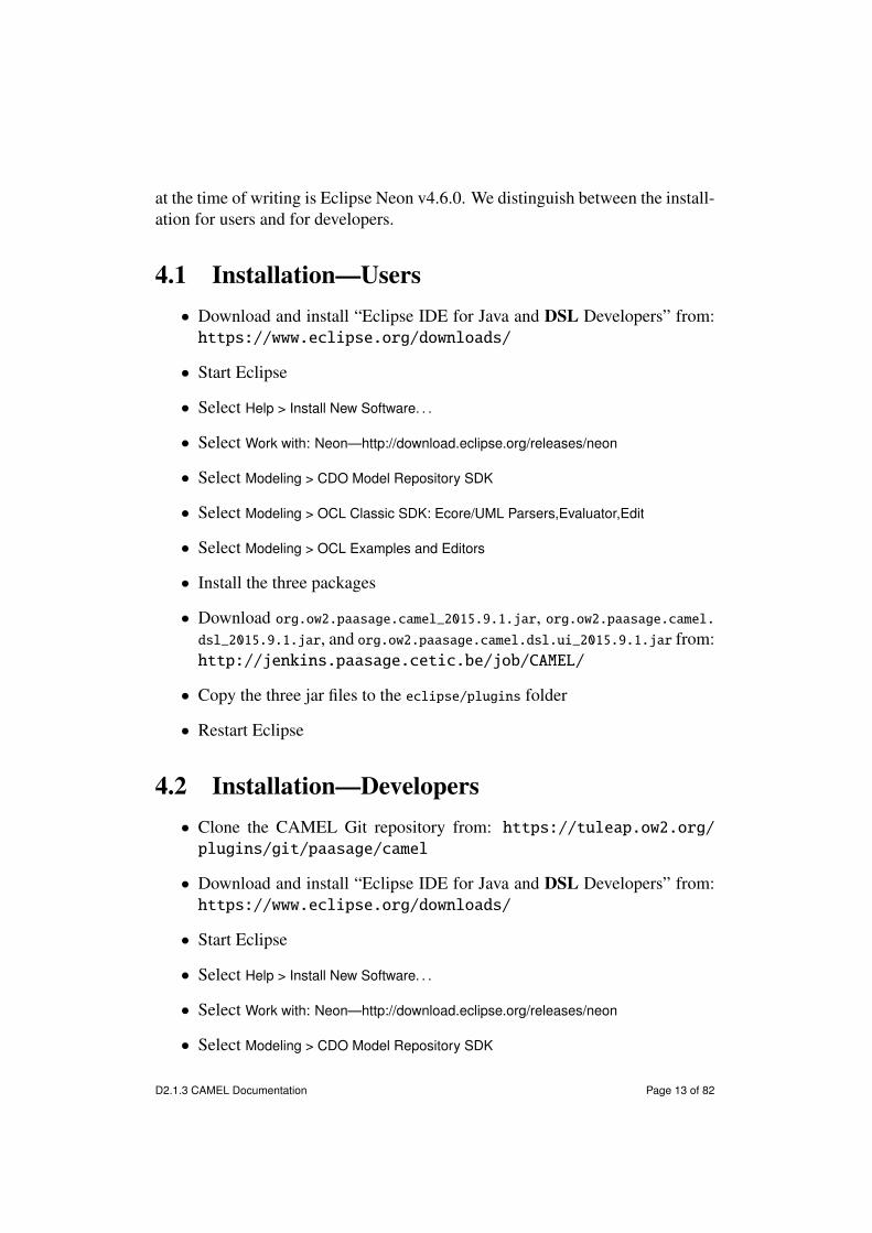
at the time of writing is Eclipse Neon v4.6.0. We distinguish between the install-ation for users and for developers.
4.1 Installation—Users• Download and install “Eclipse IDE for Java and DSL Developers” from:https://www.eclipse.org/downloads/
• Start Eclipse
• Select Help > Install New Software. . .
• Select Work with: Neon—http://download.eclipse.org/releases/neon
• Select Modeling > CDO Model Repository SDK
• Select Modeling > OCL Classic SDK: Ecore/UML Parsers,Evaluator,Edit
• Select Modeling > OCL Examples and Editors
• Install the three packages
• Download org.ow2.paasage.camel_2015.9.1.jar, org.ow2.paasage.camel.dsl_2015.9.1.jar, and org.ow2.paasage.camel.dsl.ui_2015.9.1.jar from:http://jenkins.paasage.cetic.be/job/CAMEL/
• Copy the three jar files to the eclipse/plugins folder
• Restart Eclipse
4.2 Installation—Developers• Clone the CAMEL Git repository from: https://tuleap.ow2.org/plugins/git/paasage/camel
• Download and install “Eclipse IDE for Java and DSL Developers” from:https://www.eclipse.org/downloads/
• Start Eclipse
• Select Help > Install New Software. . .
• Select Work with: Neon—http://download.eclipse.org/releases/neon
• Select Modeling > CDO Model Repository SDK
D2.1.3 CAMEL Documentation Page 13 of 82

• Select Modeling > OCL Classic SDK: Ecore/UML Parsers,Evaluator,Edit
• Select Modeling > OCL Examples and Editors
• Install the three packages
• Restart Eclipse
• Select Import > Existing Projects into Workspace
• Select Browse. . .
• Select the folder where you cloned the CAMEL Git repository
• Select Finish
• Select eu.paasage.camel.dsl/src/eu.paasage.camel.dsl/GenerateCamelDsl.mwe2
• Select Run As > MWE2 Workflow. . .
• Select eu.paasage.camel.dsl
• Select Run > Run As > Eclipse Application. . .
4.3 Usage• Add a (general) project
• Add a new file (or open an existing one) with .camel extension to theproject
• Accept to add the Xtext nature to the project
• Restart Eclipse
• Read the remainder of this document
• Edit the file
5 CAMEL Design and SyntaxCAMEL has been designed based on the following requirements, among others:
D2.1.3 CAMEL Documentation Page 14 of 82
• Cloud provider-independence (R1): CAMEL should support a cloud provi-der-agnostic specification of multiple aspects of cross-cloud applications(i.e., provisioning, deployment, service level, monitoring, scalability, pro-viders, organisations, users, roles, security, and execution). This will pre-vent vendor lock-in.
• Separation of concerns (R2): CAMEL should support loosely-coupledpackages (or modules) corresponding to multiple aspects of cross-cloudapplications. This will facilitate the development of models.
• Reusability (R3): CAMEL should support reusable types for multiple as-pects of cross-cloud applications. This will ease the evolution of models.
• Abstraction (R4): CAMEL should provide an up-to-date, abstract repres-entation of the running system. This will enable the reasoning, simulation,and validation of the adaptation actions before their enactment.
CAMEL is inspired by component-based approaches, which facilitate sep-aration of concerns (R2) and reusability (R3). In this respect, deployment mod-els can be regarded as assemblies of components exposing ports, and bindingsbetween these ports.
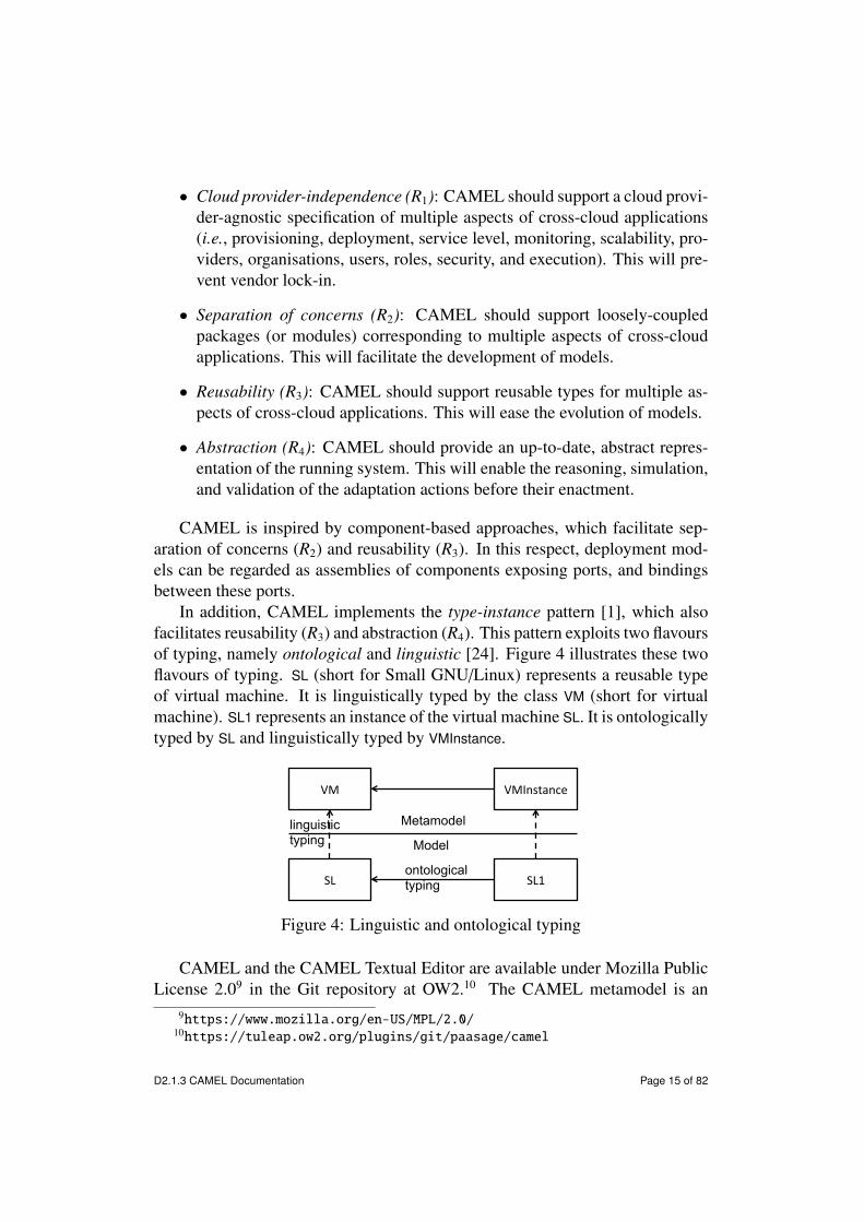
In addition, CAMEL implements the type-instance pattern [1], which alsofacilitates reusability (R3) and abstraction (R4). This pattern exploits two flavoursof typing, namely ontological and linguistic [24]. Figure 4 illustrates these twoflavours of typing. SL (short for Small GNU/Linux) represents a reusable typeof virtual machine. It is linguistically typed by the class VM (short for virtualmachine). SL1 represents an instance of the virtual machine SL. It is ontologicallytyped by SL and linguistically typed by VMInstance.
VM# VMInstance#
SL# SL1#
linguistic typing
ontological typing
Metamodel
Model
Figure 4: Linguistic and ontological typing
CAMEL and the CAMEL Textual Editor are available under Mozilla PublicLicense 2.09 in the Git repository at OW2.10 The CAMEL metamodel is an
9https://www.mozilla.org/en-US/MPL/2.0/10https://tuleap.ow2.org/plugins/git/paasage/camel
D2.1.3 CAMEL Documentation Page 15 of 82

Ecore model organised into packages, whereby each package reflects an aspect(or domain).
As mentioned, in the remainder of the document, we adopt the Scalarm11 [23]use case as a real-world running example to illustrate how to specify CAMELmodels in textual syntax. The complete Scalarm CAMEL model in textual syn-tax can be downloaded from the Git repository at OW2.12 This running examplecovers the most commonly used concepts in CAMEL. The interested reader mayrefer to [37] for a complete description of the abstract syntax of CAMEL.
Listing 5.1: Scalarm sample application1 camel model ScalarmModel {23 application ScalarmApplication {4 version: ’v1.0’5 owner: AGHOrganisation.morzech6 deployment models [ScalarmModel.ScalarmDeployment]7 }89 organisation model AGHOrganisation {
10 ...11 user morzech {12 ...13 }14 }1516 deployment model ScalarmDeployment {17 ...18 }19 }
Listing 5.1 shows an excerpt of the CAMEL model of Scalarm in textualsyntax. An element of a CAMEL model is specified by the name of the ele-ment followed by an identifier in CamelCase and a block delimited by curlybrackets. camel model ScalarmModel {...} specifies the CAMEL model of Scal-arm, where ScalarmModel represents the identifier of this model. applicationScalarmApplication specifies the Scalarm application itself.
A property is specified by the name of the property followed by a colon anda value. version: ’v1.0’ specifies that the Scalarm application has version 1.0.
A reference to a single element is specified by the name of the reference fol-lowed by a colon and a fully qualified name conforming to the pattern:id1.id2.. . . .idn, where idi refers to element at the ith level of the containmentpath and idn refers to the element at the leaf level, which is the element un-der discussion. owner: AGHOrganisation.morzech specifies that the application
11http://www.scalarm.com/12https://tuleap.ow2.org/plugins/git/paasage/camel?p=camel.git&a=blob&
f=examples/Scalarm.camel
D2.1.3 CAMEL Documentation Page 16 of 82

is owned by the user Michal Orzechowski by referring to the user morzech in theorganisation model AGHOrganisation (see Section 9, Listing 9.1).
Finally, a reference to a list of elements is specified by the name of the ref-erence followed by a comma separated list of fully qualified names delimited bysquare brackets.13 deployment models [ScalarmModel.ScalarmDeployment] spe-cifies that the Scalarm application has one deployment model by referring to thedeployment model ScalarmDeployment (see Section 6, Listing 6.1).
6 DeploymentThe deployment package of the CAMEL metamodel is based on CloudML14 [13,11, 12], which was developed in collaboration with the MODAClouds project.15
CloudML consists of a tool-supported DSL for modelling and enacting the pro-visioning and deployment of cross-cloud applications, as well as for facilitatingtheir dynamic adaptation, by leveraging MDE techniques and methods. In thefollowing, we exemplify the main concepts in the deployment package.
Assume that we have to specify the Experiment Manager component of theScalarm use case. Listing 6.1 shows this specification in textual syntax.internal component ExperimentManager specifies a reusable type of the com-
ponent Experiment Manager. provided communication ExpManPort specifies thatthe Experiment Manager provides its features through port 443. required commu-nication SimManPortReq specifies that the Experiment Manager requires featuresfrom the Simulation Manager through port 80 (cf. Listing 6.3 for the corres-ponding specification of the communication binding). The property mandatoryof SimManPortReq specifies that the Experiment Manager depends on the featuresof the Simulation Manager, and hence, that the Simulation Manager has to be de-ployed and started before the Experiment Manager. required host CoreInten-siveUbuntuNorwayReq specifies that the Experiment Manager requires a virtualmachine that provides a large number of CPU cores, runs the operating systemUbuntu, and is located in Norway (cf. Listing 6.2 for the specification of the VMand VM requirements, and Listing 6.4 for the specification of the correspondinghosting binding).configuration ExperimentManagerConfiguration specifies the commands to
handle the life cycle of the Experiment Manager. download, install, and startspecify the OS-specific shell scripts (in this case, Bash scripts) for download-ing, installing, and starting the Experiment Manager, respectively. Note that,
13Note that the colon is not used in this case.14http://cloudml.org15http://www.modaclouds.eu
D2.1.3 CAMEL Documentation Page 17 of 82

although not shown in this example, it is also possible to specify the configureand stop commands of a component.
The aforementioned commands are used by the Executionware during theexecution phase to enact the deployment of the application components and tomanage their life cycles (see Section 6.1).
Listing 6.1: Scalarm sample internal component1 deployment model ScalarmDeployment {23 internal component ExperimentManager {4 provided communication ExpManPort {port: 443}5 required communication SimManPortReq {port: 80 mandatory}6 required host CoreIntensiveUbuntuNorwayHostReq78 configuration ExperimentManagerConfiguration {9 download: ’wget http://www.scalarm.com/scalarm_exp_man.sh &&
chmod +x scalarm_exp_man.sh’10 install: ’./scalarm_exp_man.sh install’11 start: ’./scalarm_exp_man.sh start’12 }13 }14 ...
Then, assume that we have to specify the virtual machine on which the Ex-periment Manager can be deployed. Listing 6.2 shows this specification in tex-tual syntax.vm CoreIntensiveUbuntuNorway specifies a reusable type for a virtual ma-
chine. requirement set refers to the aforementioned requirement set CoreInten-siveUbuntuNorwayRS. provided host CoreIntensiveUbuntuNorwayPort specifiesthat the virtual machine provides a large number of CPU cores, runs the operat-ing system Ubuntu, and is located in Norway (cf. Listing 6.4 for the specificationof the corresponding hosting binding).requirement set CoreIntensiveUbuntuNorwayRS specifies a reusable set of re-
quirements for a virtual machine. quantitative hardware, os, and location referto the requirements CoreIntensive, Ubuntu, and NorwayReq, respectively, in therequirement model ScalarmRequirement (cf. Listing 7.1), which in turn specifythe hardware requirements encompassing a large number of CPU cores, the op-erating system requirement of Ubuntu, and the location requirement of Norway,respectively.
Listing 6.2: Scalarm sample vm1 ...2 vm CoreIntensiveUbuntuNorway {3 requirement set CoreIntensiveUbuntuNorwayRS4 provided host CoreIntensiveUbuntuNorwayPort5 }67 requirement set CoreIntensiveUbuntuNorwayRS {8 quantitative hardware: ScalarmRequirement.CoreIntensive
D2.1.3 CAMEL Documentation Page 18 of 82

9 os: ScalarmRequirement.Ubuntu10 location: ScalarmRequirement.NorwayReq11 }12 ...
Next, assume that we have to specify the communication binding betweenthe Experiment Manager and the Simulation Manager. Listing 6.3 shows thisspecification in textual syntax.communication ExperimentManagerToSimulationManager specifies a reusable
type of communication binding between the Experiment Manager and the Sim-ulation Manager. The from .. to .. block specifies that the communicationbinding is from the required communication port SimManPortReq of the com-ponent ExperimentManager to the provided communication port SimManPort ofthe component SimulationManager. type: REMOTE specifies that the ExperimentManager and the Simulation Manager must be deployed on separate virtual ma-chine instances. Note that this property could have a value ANY (default) to spe-cify that the components at each end of the communication can be deployed onany virtual machine instance(s), or LOCAL to specify that the components must bedeployed on the same virtual machine instance.
Listing 6.3: Scalarm sample communication1 ...2 communication ExperimentManagerToSimulationManager {3 from ExperimentManager.SimManPortReq to SimulationManager.
SimManPort4 type: REMOTE5 }6 ...
Finally, assume that we have to specify the hosting binding between the Ex-periment Manager and the virtual machine CoreIntensiveUbuntuNorway. List-ing 6.4 shows this specification in textual syntax.hosting ExperimentManagerToCoreIntensiveUbuntuNorway specifies a reusable
type of hosting binding between the Experiment Manager and the virtual ma-chine CoreIntensiveUbuntuNorway. The from .. to .. block specifies that thehosting binding is from the required hosting port CoreIntensiveUbuntuNorwayPort-Req of the component ExperimentManager to the provided hosting port CoreInten-siveUbuntuNorwayPortReq of the virtual machine CoreIntensiveUbuntuNorway.
Listing 6.4: Scalarm sample hosting1 ...2 hosting ExperimentManagerToCoreIntensiveUbuntuNorway {3 from ExperimentManager.CoreIntensiveUbuntuNorwayPortReq to
CoreIntensiveUbuntuNorway.CoreIntensiveUbuntuNorwayPort4 }5 ...
D2.1.3 CAMEL Documentation Page 19 of 82

The types presented above can be instantiated in order to form a CPSM. InPaaSage, the instances within the deployment model are automatically manip-ulated during the deployment phase (see Section 2). In the general case, theinstances could also be manipulated manually. Note that di↵erent CPSMs canadopt di↵erent instantiation patterns for communications and hosting bindings,while still conforming to the same CPIM. The interested reader may refer to [7]for an extensive discussion on the subject.
Listing 6.5 shows the specification of instances of the components, virtualmachines, communications, and hosting bindings from the previous examples(cf. Listings 6.1, 6.2, 6.3, and 6.4) in textual syntax.vm instance CoreIntensiveUbuntuNorwayInst specifies an instance of a vir-
tual machine. vm type and vm type value refer to the virtual machine flavourM1.LARGE in the provider model SINTEFProvider (cf. Listing 10.1), which is com-patible with the requirement set of the virtual machine template CoreIntensive-UbuntuNorway (cf. Listing 7).internal component instance ExperimentManagerInst specifies an instance of
the component ExperimentManager. The connect .. to .. typed .. and host.. on .. typed .. blocks specify instances of the communication Experiment-ManagerToSimulationManager and the hosting ExperimentManagerToCoreIntensive-UbuntuNorway, respectively. typed refers to the identifier of the correspondingtype.
Listing 6.5: Scalarm sample instances of internal component, vm, communication,and hosting
1 ...2 vm instance CoreIntensiveUbuntuNorwayInst typed ScalarmModel.
ScalarmDeployment.CoreIntensiveUbuntuNorway {3 vm type: ScalarmModel.SINTEFProvider.SINTEF.VM.VMType4 vm type value: ScalarmModel.SINTEFType.VMTypeEnum.M1.LARGE5 provided host instance CoreIntensiveUbuntuNorwayHostInst typed
CoreIntensiveUbuntuNorway.CoreIntensiveUbuntuNorwayHost6 }78 internal component instance SimulationManagerInst typed ScalarmModel
.ScalarmDeployment.SimulationManager {9 provided communication instance SimManPortInst typed
SimulationManager.SimManPort10 required host instance SimulationIntensiveUbuntuNorwayHostReqInst
typed SimulationManager.SimulationIntensiveUbuntuNorwayHostReq11 }1213 internal component instance ExperimentManagerInst typed ScalarmModel
.ScalarmDeployment.ExperimentManager {14 provided communication instance ExpManPortInst typed
ExperimentManager.ExpManPort15 required communication instance SimManPortReqInst typed
ExperimentManager.Si,ManPortReq16 required host instance CoreIntensiveUbuntuNorwayHostReqInst typed
ExperimentManager.CoreIntensiveUbuntuNorwayHostReq
D2.1.3 CAMEL Documentation Page 20 of 82

17 }1819 connect ExperimentManagerInst.SimManPortReqInst to
SimulationManagerInst.SimManPortInst typed ScalarmModel.ScalarmDeployment.ExperimentManagerToSimulationManager
2021 host ExperimentManagerInst.CoreIntensiveUbuntuNorwayHostReqInst on
CoreIntensiveUbuntuNorwayInst.CoreIntensiveUbuntuNorwayHostInsttyped ScalarmModel.ScalarmDeployment.ExperimentManagerToCoreIntensiveUbuntuNorway
22 ...
6.1 Interplay with ExecutionwareIn order to execute a cloud application, the Executionware provisions VMs, de-ploys one or more component instances on these VMs, and starts these instancesby relying on a cross-cloud orchestration framework. In PaaSage, this cross-cloud orchestration framework is Cloudiator [6]. Note the Executionware cansolely rely on the information provided in a CAMEL model. Hence, the Execu-tionware does not make any assumptions besides the information provided.
In order to steer the individual instances of internal components, the Execu-tionware relies on handlers that have been specified in the configuration of aninternal component. The handlers are invoked in the following order:
1. download
2. install
3. configure
4. start
6.1.1 Life Cycle Scripts for Unix-based ApplicationsAs stated above, the Executionware relies on the deployment model within aCAMEL model, and in particular on the configuration block of internal compo-nents, in order to manage the component instances. For GNU/Linux deploy-ments, all of the handlers are executed as a single Unix shell script (e.g., com-patible with Bash) that has to be specified in the configuration block of internalcomponents (e.g., for downloading the executable code of the component). A re-turn value di↵erent from 0 is interpreted as an error and causes the componentinstance to move to an error state. Data about ports and connection informationas well as the local host is provided via environment variables.
D2.1.3 CAMEL Documentation Page 21 of 82

Note that the di↵erent handlers are not necessarily executed in the very sameinstance of the Unix shell. This means that custom environment variables setin a handler (e.g., in the download command) are not necessarily available inlater handlers. If such information is required, the only approach is to write thenecessary data to a file and source this file in later handlers. For GNU/Linuxdeployments, all component instances are run within an own Docker container16
in order to enable a maximum of isolation between the instances. This has aconsequence for user handling and networking: As for the users, this means thatall commands are executed as root. Also, the handlers cannot assume that anyother user beside root exists in the system. Hence, if further users are required,the handlers are responsible for creating them. As for networking, the e↵ects onboth IP addresses and port numbers are discussed in the following.
IP Addresses in the Execution Environment. First, all components have atleast two IP addresses, namely the IP address of their Docker container and theIP address of the virtual machine this container is hosted on. Often, the IP of thevirtual machine is a cloud-internal IP address that is not routed outside the cloudprovider. Hence, it is very likely that there is a third IP address involved thatrepresents the public IP address of the virtual machine. All three IP addressesare passed to configuration and start handlers as environment variables usingthe following formats:
• CONTAINER_IP: the IP address of the container. It should be used for bindingpurposes.
• CLOUD_IP: the IP address of the virtual machine running the container. ThisIP is probably cloud provider-specific and cannot be reached from outsidethe cloud.
• PUBLIC_IP: the public IP address of the virtual machine running the con-tainer, if available.
Port Numbers in the Execution Environment. Moreover, the port numbersused within the container do not necessarily match the port numbers used by theoperating system hosting the Docker container. Indeed, the Executionware willnot force the use of any fixed port numbers outside the container in order to allowmaximum flexibility. Again, the port numbers are passed to the configurationand start handlers as environment variables. The name of the variable is based
16http://docker.io
D2.1.3 CAMEL Documentation Page 22 of 82

on the name of the provided communication from the deployment model. For in-stance, the provided port ExpManPort from Listing 6.1 is mapped to the followingthree environment variables:
• CONTAINER_EXPMANPORT: the port number as specified in the deploymentmodel and as accessible from within the container. Should be used forbinding.
• CLOUD_EXPMANPORT: the port number as accessible from within the cloud.
• PUBLIC_EXPMANPORT: the port number as accessible from the outside world(i.e., by using the public IP).
Outgoing Connections in the Execution Environment. Similar to the provid-ed communications, there is a mapping for required communications. The maindi↵erence is that it uses sets of IP addresses in combination with ports. Forinstance, the required port StoManPortReq from Listing 6.1 is mapped to the fol-lowing three environment variables; all consisting of a sequence of ipv4:portseparated by a comma (,).
• PUBLIC_STOMANPORTREQ: provides access to the public IP addresses and pub-lic ports of all downstream component instances.<stoman1publicip>:<public_port>,<stoman2publicip>:<public_port>
• CLOUD_STOMANPORTREQ: provides access to the cloud-internal IP addressesand cloud-internal ports of all downstream component instances. Notethat the addresses of component instances that are not hosted in the samecloud as the local component instances are still in the list, but it is verylikely that tra�c cannot be routed to them.<stoman1cloudip>:<cloud_port>,<stoman2cloudip>:<cloud_port>
• CONTAINER_STOMANPORTREQ: provides access to the container-internal IP ad-dresses and container-internal ports of all downstream component instances.Note that the addresses of component instances that are not hosted in thesame container as the local component instances are still in the list, but itis very likely that tra�c cannot be routed to them.<stoman1containerip>:<container_port>,<stoman2containerip>:
<container_port>
Currently, it is up to the CAMEL user to decide which of the combinationsis needed. Using the public IPs and ports enables a full routability of networktra�c, but may introduce networking overhead. Future work may improve uponthis status quo by providing the shortest distance combinations of the addresses.
D2.1.3 CAMEL Documentation Page 23 of 82

Updating Required Communications. Whenever the set of downstream in-stances changes (e.g., a new Storage Manager instance is created), the starthandler of the associated required communication is invoked. This should leadto an updated configuration and if necessary a re-started main process.
The Start Life Cycle Scripts. The life cycle script attached to start is a spe-cial script. It is supposed to not return from its call. As such, the ExecutionEnvironment will use exec <install command from CAMEL>. This means that theCAMEL user shall not use more than one command in the install handler, ase.g., cd directory && ./run.sh will not work. The same holds for cd directory; ./run.sh. Use directory/run.sh instead.
Other Environment Variables. Per default, Docker uses only very few en-vironment variables in a default container, except for HOME (home of the currentuser—root by default), PWD (current working directory—/ by default), and PATH.Users should not rely on any of these.
6.1.2 Life Cycle Scripts for Windows-based ApplicationsFor Windows-based deployments the Executionware relies on the same deploy-ment model as GNU/Linux deployments, mainly the configuration block ofinternal components. All handlers are executed as a single Powershell script.The return value will be interpreted and a value di↵erent from 0 will move theinstance to an error state. Information about ports, connection and the local hostis provided via environment variables.
Like on GNU/Linux, the di↵erent handlers are not necessarily executed inthe very same shell instance, in particular the same Powershell instance. If cus-tom environment variables are set in a handler which will be used in a later hand-ler they have to be set on the user-level. In Powershell this can be achieved withthe command [Environment]::SetEnvironmentVariable($NAME, $VALUE, "User").$NAME and $VALUE represent the respective parameters and the static value "User"specifies the user-level for the environment variable. For Windows deploymentsevery component runs in its own folder. All commands are executed as Adminis-trator and no other existing users can be assumed. If further users are required,the handlers are responsible for creating them. The networking is discussed inthe following.
IP Addresses in the Execution Environment. Unlike Unix components, Win-dows components have at least one IP address. Depending on the cloud provider,it is possible that this IP is a cloud-internal IP and there is a second IP address
D2.1.3 CAMEL Documentation Page 24 of 82

that represents the public IP address of the virtual machine. Both IP addressesare passed to configuration and start handlers as environment variables:
• CLOUD_IP: the IP address of the virtual machine running the component.This IP is probably cloud provider-specific and cannot be reached fromoutside the cloud.
• PUBLIC_IP: the public IP address of the virtual machine running the com-ponent, if available.
Port Numbers in the Execution Environment. As Windows components justrun in an unique folder and not in a container like Unix components there isa small di↵erence. The port numbers of Windows components match the portnumbers of the virtual machine’s operating system. The port numbers are passedto the configuration and start handlers as environment variables. The nameof the variable is based on the name of the provided communication from thedeployment model. Considering the example from Listing 6.1 as a Windowscomponent the resulting two environment variables are set:
• CLOUD_EXPMANPORT: the port number as accessible from within the cloud.
• PUBLIC_EXPMANPORT: the port number as accessible from the outside world(i.e., by using the public IP).
Outgoing Connections in the Execution Environment. The mapping of re-quired communications is similar to Unix components (cf. Section 6.1.1) exceptthere is no need to map the communication to a container-internal IP. Again,consider Listing 6.1 as a Windows component the required port is mapped to thefollowing environment variables:
• PUBLIC_STOMANPORTREQ: provides access to the public IP addresses and pub-lic ports of all downstream component instances.<stoman1publicip>:<public_port>,<stoman2publicip>:<public_port>
• CLOUD_STOMANPORTREQ: provides access to the cloud-internal IP addressesand cloud-internal ports of all downstream component instances. Notethat addresses of component instances not hosted in the same cloud asthe local component instance are still in the list, but very likely cannot berouted to.<stoman1cloudip>:<cloud_port>,<stoman2cloudip>:<cloud_port>
D2.1.3 CAMEL Documentation Page 25 of 82

Updating Required Communications. Whenever the set of downstream in-stances changes (e.g., a new Storage Manager instance is created), the starthandler of the associated required communication is invoked. This should leadto an updated configuration and if necessary a re-started main process.
The Start Life Cycle Scripts. In contrast to Unix components, for Windowscomponents the start command is supposed to return from its call. It is alsopossible to use more than one command like in all other handlers.
Other Environment Variables. The default Windows environment variablesare set (e.g., HOMEPATH or ProgramData), but the user should be aware that theenvironment variables can di↵er depending on the operating system version.
7 RequirementsThe requirement package of the CAMEL metamodel is not based on existingDSLs and has been developed to enable the specification of requirements forcross-cloud applications. A requirement can be hard, such as a service levelobjective (SLO) (e.g., response time < 100 ms), meaning that it is measurableand must be satisfied, or soft, such as a optimisation objective (e.g., maximiseperformance), meaning that it is not measurable. A soft requirement has a pri-ority from 0.0 to 1.0 that is used to rank these requirements when reasoning onthe application and generating a new CPSM. In the following, we exemplify themain concepts in the requirement package.
Assume that we have to specify the requirements for the components of theScalarm use case. Listing 7.1 shows this specification in textual syntax.quantitative hardware CoreIntensive specifies that a virtual machine must
have from 8 to 32 CPU cores and from 4 to 8 GB of RAM. os Ubuntu spe-cifies that a virtual machine must run Ubuntu operating system 64-bit edition.location requirement NorwayReq specifies that a virtual machine must be de-ployed in Norway. locations refers to the location NO in the location modelScalarmLocation (cf. Listing 13.1). The three requirements above are referred toby the requirement set CoreIntensiveUbuntuNorwayRS in the deployment modelScalarmDeployment (cf. Listing 6.2).slo CPUMetricSLO specifies that the metric condition CPUMetricCondition is
an SLO. service level refers to the metric condition CPUMetricCondition in themetric model ScalarmModel (cf. Listing 8.2).optimisation requirement MinimisePerformanceDegradationOfExperimentMan-
ager specifies that the metric MeanValueOfResponseTimeOfAllExprimentManagers-Metric of the component ExperimentManager should be minimised and that this
D2.1.3 CAMEL Documentation Page 26 of 82

minimisation has a priority 0.8. metric refers to the metric MeanValueOfResponse-TimeOfAllExprimentManagersMetric in the metric model ScalarmModel (cf. List-ing 8.2), while component refers to the internal component ExperimentManager inthe deployment model ScalarmDeployment (cf. Listing 6.2). optimisation require-ment MinimiseDataFarmingExperimentMakespan specifies a similar optimisation re-quirement with priority 0.2.group ScalarmRequirementGroup specifies that the requirements CPUMetricSLO,
MinimisePerformanceDegradationOfExperimentManager, and MinimiseDataFarming-ExperimentMakespan are logically connected through the AND operator. Note thata requirement group also allows a requirement tree to be created. For example,a top-level requirement group could contain two or more requirement groups lo-gically connected by an OR operator. Each of the latter requirement groups couldin turn contain single requirements, such as SLOs, logically connected by an ANDoperator.horizontal scale requirement HorizontalScaleSimulationManager specifies
that the component SimulationManager can scale horizontally between 1 and 5instances. component refers to the internal component SimulationManager in thedeployment model ScalarmDeployment (cf. Listing 6.2).
Listing 7.1: Scalarm requirement model1 requirement model ScalarmRequirement {23 quantitative hardware CoreIntensive {4 core: 8..325 ram: 4096..81926 }78 os Ubuntu {9 os: ’Ubuntu’ 64os
10 }1112 location requirement NorwayReq {13 locations [ScalarmLocation.NO]14 }1516 slo CPUMetricSLO {17 service level: ScalarmModel.ScalarmMetric.CPUMetricCondition18 }1920 optimisation requirement
MinimisePerformanceDegradationOfExperimentManager {21 function: MIN22 metric: ScalarmModel.ScalarmMetric.
MeanValueOfResponseTimeOfAllExprimentManagersMetric23 component: ScalarmModel.ScalarmDeployment.ExperimentManager24 priority: 0.825 }2627 optimisation requirement MinimiseDataFarmingExperimentMakespan {28 function: MIN
D2.1.3 CAMEL Documentation Page 27 of 82

29 metric: ScalarmModel.ScalarmMetric.MakespanMetric30 component: ScalarmModel.ScalarmDeployment.ExperimentManager31 priority: 0.232 }3334 group ScalarmRequirementGroup {35 operator: AND36 requirements [ScalarmRequirement.CPUMetricSLO , ScalarmRequirement.
MinimisePerformanceDegradationOfExperimentManager ,ScalarmRequirement.MinimiseDataFarmingExperimentMakespan]
37 }3839 horizontal scale requirement HorizontalScaleSimulationManager {40 component: ScalarmModel.ScalarmDeployment.SimulationManager41 instances: 1 .. 542 }43 }
8 Metrics and Scalability RulesThe scalability and metric packages of the CAMEL metamodel are based on theScalability Rule Language (SRL) [20, 8]. SRL enables the specification of rulesthat support complex adaptation scenarios of cross-cloud applications. In partic-ular, SRL provides mechanisms for specifying cross-cloud behaviour patterns,metric aggregations, and the scaling actions to be enacted in order to change theprovisioning and deployment of an application. SRL is inspired by the EsperProcessing Language (EPL)17 with respect to the specification of event patternswith formulas including logic operators and timing. SRL provides mechanismsfor (a) specifying event patterns, (b) specifying scaling actions, and (c) associ-ating these scaling actions with the corresponding event patterns. Moreover, inorder to identify event patterns, the components of cross-cloud applications mustbe monitored. Therefore, SRL provides mechanisms for (d) expressing whichcomponents must be monitored by which metrics, and (e) associating event pat-terns with monitoring data. In the following, we exemplify the main concepts inthe scalability and metric packages.
Assume that we have to specify scalability rules and metrics for the Scalarmuse case. The SimulationManager scales out when the following conditions aremet: (a) all instances have had an average CPU load beyond 50% for at least5 min, and (b) concurrently at least one instance has had an average CPU loadbeyond 80% for at least 1 min. These conditions are represented by the followingexpression, where cpui and cpuj represent the average CPU loads for instance iand j, respectively:
17http://esper.codehaus.org/
D2.1.3 CAMEL Documentation Page 28 of 82
8i | cpui � 50 ^ 9 j | cpuj � 80
To implement this scenario, we specified a scalability and a metric modelthat represent, respectively: (a) the scalability rule along with the events usedto trigger it, and (b) the metrics and conditions that, when evaluated, trigger theaction of the scalability rule.
Listing 8.1 shows the scalability model in textual syntax. non-functionalevent CPUAvgMetricNFEAll specifies the violation of a metric condition. metriccondition refers to the metric condition CPUAvgMetricConditionAll in the metricmodel ScalarmMetric (cf. Listing 8.2). non-functional event CPUAvgMetricNFEAnyspecifies a similar violation of a metric condition.binary event pattern CPUAvgMetricBEPAnd specifies that the non-functional
events above are logically connected through an AND operator.horizontal scaling action HorizontalScalingSimulationManager specifies a
scale-out action. vm and internal component refer to the vm CPUIntensiveUbuntu-Norway and the internal component SimulationManager, respectively, in the de-ployment model ScalarmDeployment (cf. Listings 6.2 and 6.1).scalability rule CPUScalabilityRule refers to the binary event pattern and
the horizontal scaling action above, along with the scale requirement Horizon-talScaleSimulationManager in the requirement model ScalarmRequirement (cf.Listing 7.1).
Listing 8.1: Scalarm scalability model1 scalability model ScalarmScalability {23 non-functional event CPUAvgMetricNFEAll {4 metric condition: ScalarmModel.ScalarmMetric.
CPUAvgMetricConditionAll5 violation
6 }78 non-functional event CPUAvgMetricNFEAny {9 metric condition: ScalarmModel.ScalarmMetric.
CPUAvgMetricConditionAny10 violation
11 }1213 binary event pattern CPUAvgMetricBEPAnd {14 left event: ScalarmModel.ScalarmScalability.CPUAvgMetricNFEAll15 right event: ScalarmModel.ScalarmScalability.CPUAvgMetricNFEAny16 operator: AND17 }1819 horizontal scaling action HorizontalScalingSimulationManager {20 type: SCALE_OUT21 vm: ScalarmModel.ScalarmDeployment.CPUIntensiveUbuntuNorway
D2.1.3 CAMEL Documentation Page 29 of 82

22 internal component: ScalarmModel.ScalarmDeployment.SimulationManager
23 }2425 scalability rule CPUScalabilityRule {26 event: ScalarmModel.ScalarmScalability.CPUAvgMetricBEPAnd27 actions [ScalarmModel.ScalarmScalability.
HorizontalScalingSimulationManager]28 scale requirements [ScalarmRequirement.
HorizontalScaleSimulationManager]29 }30 }
Listing 8.2 shows the metric model in textual syntax. raw metric CPUMetric,along with the elements referred by it, specify a raw (sensor) metric meas-uring CPU load. composite metric CPUAverage, along with the elements re-ferred by it, specify an average CPU load metric. composite metric contextCPUAvgMetricContextAll and composite metric context CPUAvgMetricContextAnyspecify that the average CPU load metric is instantiated in two contexts, one witha window of five minutes and one with a window of one minute, respectively.The aggregated composite metrics are instantiated as metric instances twice pervirtual machine, and once per metric context.
Listing 8.2: Scalarm metric model1 metric model ScalarmMetric {23 window Win5Min {4 window type: SLIDING5 size type: TIME_ONLY6 time size: 57 unit: ScalarmModel.ScalarmUnit.minutes8 }9
10 window Win1Min {11 window type: SLIDING12 size type: TIME_ONLY13 time size: 114 unit: ScalarmModel.ScalarmUnit.minutes15 }1617 schedule Schedule1Min {18 type: FIXED_RATE19 interval: 120 unit: ScalarmModel.ScalarmUnit.minutes21 }2223 schedule Schedule1Sec {24 type: FIXED_RATE25 interval: 126 unit: ScalarmModel.ScalarmUnit.seconds27 }2829 sensor CPUSensor {
D2.1.3 CAMEL Documentation Page 30 of 82

30 configuration: ’cpu_usage;de.uniulm.omi.cloudiator.visor.sensors.CpuUsageSensor ’
31 push
32 }3334 property CPUProperty {35 type: MEASURABLE36 sensors [ScalarmMetric.CPUSensor]37 }3839 raw metric CPUMetric {40 value direction: 041 layer: IaaS42 property: ScalarmModel.ScalarmMetric.CPUProperty43 unit: ScalarmModel.ScalarmUnit.CPUUnit44 value type: ScalarmModel.ScalarmType.Range0_10045 }4647 raw metric context CPURawMetricContext {48 metric: ScalarmModel.ScalarmMetric.CPUMetric49 sensor: ScalarmMetric.CPUSensor50 component: ScalarmModel.ScalarmDeployment.SimulationManager51 schedule: ScalarmModel.ScalarmMetric.Schedule1Sec52 quantifier: ALL53 }5455 raw metric context CPUMetricConditionContext {56 metric: ScalarmModel.ScalarmMetric.CPUMetric57 sensor: ScalarmMetric.CPUSensor58 component: ScalarmModel.ScalarmDeployment.SimulationManager59 quantifier: ANY60 }6162 composite metric CPUAverage {63 description: "Average of the CPU"64 value direction: 165 layer: PaaS66 property: ScalarmModel.ScalarmMetric.CPUProperty67 unit: ScalarmModel.ScalarmUnit.CPUUnit6869 metric formula FormulaAverage {70 function arity: UNARY71 function pattern: MAP72 MEAN( ScalarmModel.ScalarmMetric.CPUMetric )73 }74 }7576 composite metric context CPUAvgMetricContextAll {77 metric: ScalarmModel.ScalarmMetric.CPUAverage78 component: ScalarmModel.ScalarmDeployment.SimulationManager79 window: ScalarmModel.ScalarmMetric.Win5Min80 schedule: ScalarmModel.ScalarmMetric.Schedule1Min81 composing metric contexts [ScalarmModel.ScalarmMetric.
CPURawMetricContext]82 quantifier: ALL83 }8485 composite metric context CPUAvgMetricContextAny {86 metric: ScalarmModel.ScalarmMetric.CPUAverage
D2.1.3 CAMEL Documentation Page 31 of 82

87 component: ScalarmModel.ScalarmDeployment.SimulationManager88 window: ScalarmModel.ScalarmMetric.Win1Min89 schedule: ScalarmModel.ScalarmMetric.Schedule1Min90 composing metric contexts [ScalarmModel.ScalarmMetric.
CPURawMetricContext]91 quantifier: ANY92 }9394 metric condition CPUMetricCondition {95 context: ScalarmModel.ScalarmMetric.CPUMetricConditionContext96 threshold: 80.097 comparison operator: >98 }99
100 metric condition CPUAvgMetricConditionAll {101 context: ScalarmModel.ScalarmMetric.CPUAvgMetricContextAll102 threshold: 50.0103 comparison operator: >104 }105106 metric condition CPUAvgMetricConditionAny {107 context: ScalarmModel.ScalarmMetric.CPUAvgMetricContextAny108 threshold: 80.0109 comparison operator: >110 }111 }
8.1 Interplay with ExecutionwareIn order to enact the scalability rules, the Executionware provides a monitoringand adaptation engine for cross-cloud applications. In PaaSage, this monitoringand adaptation engine is Axe [9]. In particular, the Executionware configuresthe monitoring probes based on the specified metrics and evaluates the specifiedscalability rules. If a metric condition is violated, the Executionware enacts thespecified scaling action (e.g., scale-out), which may include the provisioning ofvm instances, the deployment of component instances, and the wiring of these(see Section 6.1). Life-cycle handlers attached to the specified communicationscan wire existing component instances by reconfiguring them. The interestedreader may refer to [9] for a detailed description of how the Executionware en-acts scaling actions.
9 OrganisationsThe organisation package of the CAMEL metamodel is based on the organisa-tion subset of CERIF [18]. CERIF is an EU standard18 for research information.
18http://cordis.europa.eu/cerif/
D2.1.3 CAMEL Documentation Page 32 of 82

In particular, the organisation package of the CAMEL reuses the concepts fromCERIF for specifying organisations, users, and roles. In the following, we ex-emplify the main concepts in the organisation package.
Assume that we have to specify the organisation model for the Scalarm usecase. Listing 9.1 shows this specification in textual syntax.organisation AGH specifies the organisation AGH (Akademia Górniczo-Hut-
nicza, i.e., AGH University of Science and Technology), while user MichalOrze-chowski specifies the user Michal Orzechowski belonging to the organisationAGH and owning the application Scalarm (cf. Listing 5.1).role devop specifies the role development and operations (devop), while role
assignment MichalOrzechowskiDevop specifies the assignment of the role devop tothe user Michal Orzechowski, which is valid from 1 March 2016 to 28 February2017.
Listing 9.1: Scalarm organisation model1 organisation model AGHOrganisation {23 organisation AGH {4 www: ’http://www.agh.edu.pl/en/’5 email: ’[email protected]’6 }78 user MichalOrzechowski {9 first name: Michal
10 last name: Orzechowski11 email: ’[email protected]’12 password: ’************’13 }1415 role devop1617 role assignment MichalOrzechowskiDevop {18 start: 2016-03-0119 end: 2017-02-2820 assigned on: 2016-02-2921 user: AGHOrganisation.morzech22 role: ScalarmModel.AGHOrganisation.devop23 }24 }
10 ProvidersThe provider package of the CAMEL metamodel is based on Saloon [32, 33, 34].Saloon is a tool-supported DSL for specifying the features of cloud providersand matching them with requirements by leveraging feature models [3] and on-tologies [17]. In the following, we exemplify the main concepts in the providerpackage.
D2.1.3 CAMEL Documentation Page 33 of 82

Assume that we have to specify the provider model for the Scalarm use case.Listing 10.1 shows an excerpt of the provider model for a SINTEF private cloudspecified using the CAMEL textual syntax.root feature SINTEF is the root feature and specifies the attributes and sub-
features characterising SINTEF’s private cloud. attribute DeliveryModel spe-cifies that SINTEF provides a private cloud. attribute ServiceModel specifiesthat SINTEF provides a IaaS. attribute Availability specifies that the guaran-teed availability of SINTEF’s private cloud is 95%. attribute Driver specifiesthat the provider uses an OpenStack Nova API. attribute EndPoint specifies theendpoint of the SINTEF’s OpenStack Nova API.feature VM is a sub-feature and specifies the attributes characterising the vir-
tual machine flavours provided by SINTEF’s private cloud, such as type (attri-bute VMType), operating system (attribute VMOS), size of RAM (attribute VM-Memory), size of storage (attribute VMStorage), and number of CPU cores (attri-bute VMCores). Each attribute has a value type, and a unit type. For instance,VMMemory has MemoryList, a list of integer values (256, 512, 2048, etc.), as valuetype, and MEGABYTES as unit type (cf. Listings 15.1 and 14.1). feature cardinalityspecifies that the feature has a cardinality between 1 and 8.constraints specifies the constraints characterising SINTEF’s private cloud.
implies M1LARGEMapping is an intra-feature constraint and specifies the mappingbetween the assigned resources and the virtual machine flavours provided bySINTEF’s private cloud. For instance, the first attribute constraint specifiesthat the size of RAM of the M1.LARGE virtual machine flavour is 8192 (mega-bytes).
Listing 10.1: SINTEF provider model (excerpt)1 provider model SINTEFProvider {23 root feature SINTEF {45 attributes {67 attribute DeliveryModel {8 value: string value ’Private’9 value type: ScalarmModel.SINTEFType.StringValueType
10 }1112 attribute ServiceModel {13 value: string value ’IaaS’14 value type: ScalarmModel.SINTEFType.StringValueType15 }1617 attribute Availability {18 unit type: PERCENTAGE19 value: string value ’95’20 value type: ScalarmModel.SINTEFType.StringValueType21 }22
D2.1.3 CAMEL Documentation Page 34 of 82

23 attribute Driver {24 value: string value ’openstack -nova’25 value type: ScalarmModel.SINTEFType.StringValueType26 }2728 attribute EndPoint {29 value: string value ’https://minicloud.modelbased.net’30 value type: ScalarmModel.SINTEFType.StringValueType31 }32 }3334 sub-features {3536 feature VM {3738 attributes {39 attribute VMType {value type: ScalarmModel.SINTEFType.
VMTypeEnum}40 attribute VMOS {value type: ScalarmModel.SINTEFType.VMOSEnum
}41 attribute VMMemory {unit type: MEGABYTES value type:
ScalarmModel.SINTEFType.MemoryList}42 attribute VMStorage {unit type: GIGABYTES value type:
ScalarmModel.SINTEFType.StorageList}43 attribute VMCores {value type: ScalarmModel.SINTEFType.
CoresList}44 }4546 feature cardinality {cardinality: 1 .. 8}47 }48 ...49 }5051 feature cardinality {cardinality: 1 .. 1}52 }5354 constraints {55 ...56 implies M1LARGEMapping {5758 from: ScalarmModel.SINTEFProvider.SINTEF.VM59 to: ScalarmModel.SINTEFProvider.SINTEF.VM6061 attribute constraints {6263 attribute constraint {64 from: ScalarmModel.SINTEFProvider.SINTEF.VM.VMType65 to: ScalarmModel.SINTEFProvider.SINTEF.VM.VMMemory66 from value: string value ’M1.LARGE’67 to value: int value 819268 }6970 attribute constraint {71 from: ScalarmModel.SINTEFProvider.SINTEF.VM.VMType72 to: ScalarmModel.SINTEFProvider.SINTEF.VM.VMCores73 from value: string value ’M1.LARGE’74 to value: int value 475 }76
D2.1.3 CAMEL Documentation Page 35 of 82

77 attribute constraint {78 from: ScalarmModel.SINTEFProvider.SINTEF.VM.VMType79 to: ScalarmModel.SINTEFProvider.SINTEF.VM.VMStorage80 from value: string value ’M1.LARGE’81 to value: int value 8082 }83 }84 }85 ...86 }87 }
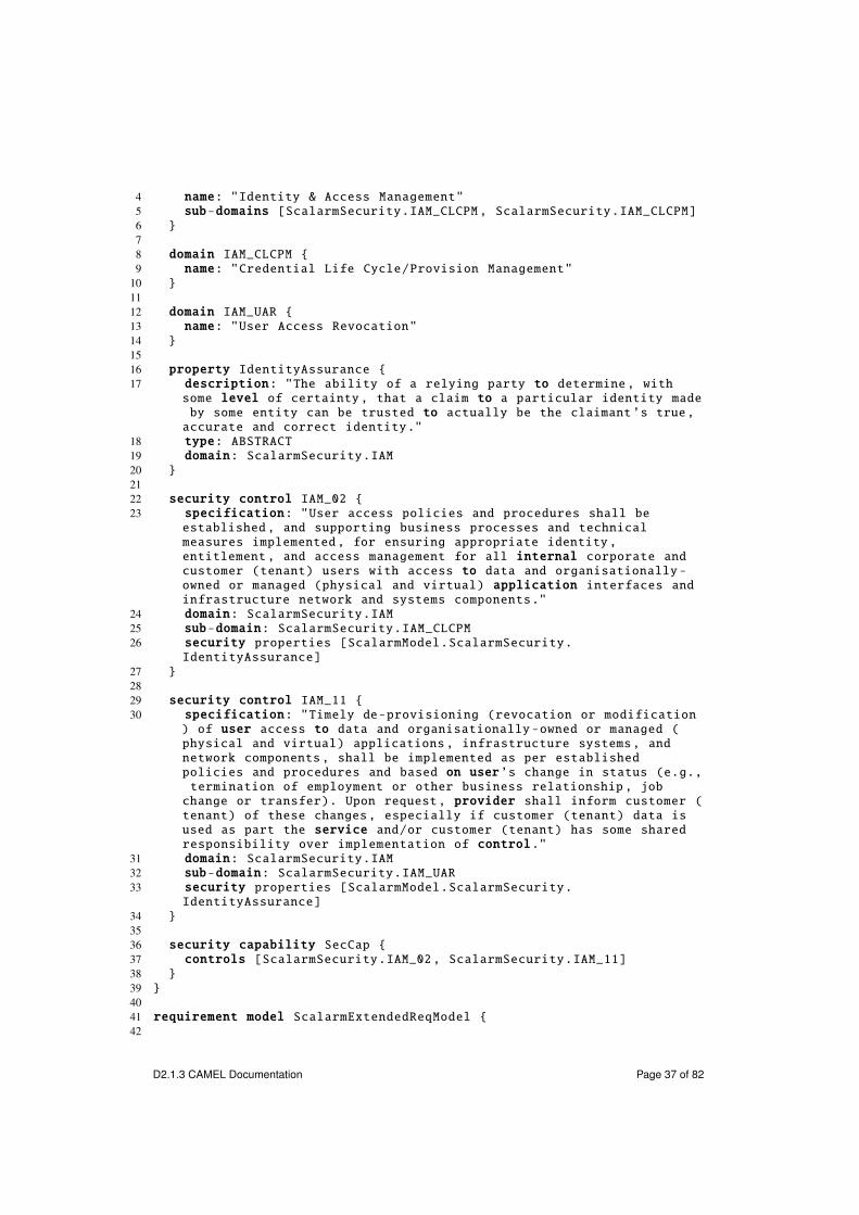
11 SecurityThe security package of the CAMEL metamodel is not based on existing DSLsand has been developed to enable the specification of security aspects of cross-cloud applications. It enables the specification of high-level and low-level se-curity requirements and capabilities that can be exploited for filtering providersas well as adapting cross-cloud applications. In the following, we exemplify themain concepts in the security package.
Assume that we have to specify the security model for the Scalarm use case.Listing 9.1 shows this specification in textual syntax.domain IAM specifies the domain of Identity & Access Management (IAM).
domain IAM_CLCPM and IAM_UAR specify two sub-domains of IAM, namely Creden-tial Life Cycle/Provision Management (CLCPM) and User Access Revocation(UAR), respectively.property IdentityAssurance specifies an abstract property of identity assur-
ance associated with the domain IAM. security control IAM_02 specifies a se-curity control associated with the sub-domain (CLCPM) and the property Identi-tyAssurance. Similarly, security control IAM_11 specifies a security control as-sociated with the sub-domain (UAR) and the property IdentityAssurance. Notethat these security controls are part of the set of security controls identified bythe Cloud Security Alliance (CSA).19
security capability SecCap specifies a security capability associated withthe security controls IAM_02 and IAM_11. Finally, the organisation model Amazon-Ext refers to the security capability SecCap, which specifies that the Amazonprovider supports this security capability.
Listing 11.1: Scalarm security model1 security model ScalarmSecurity {23 domain IAM {
19https://cloudsecurityalliance.org/
D2.1.3 CAMEL Documentation Page 36 of 82
4 name: "Identity & Access Management"5 sub-domains [ScalarmSecurity.IAM_CLCPM , ScalarmSecurity.IAM_CLCPM]6 }78 domain IAM_CLCPM {9 name: "Credential Life Cycle/Provision Management"
10 }1112 domain IAM_UAR {13 name: "User Access Revocation"14 }1516 property IdentityAssurance {17 description: "The ability of a relying party to determine , with
some level of certainty , that a claim to a particular identity madeby some entity can be trusted to actually be the claimant ’s true,accurate and correct identity."
18 type: ABSTRACT19 domain: ScalarmSecurity.IAM20 }2122 security control IAM_02 {23 specification: "User access policies and procedures shall be
established , and supporting business processes and technicalmeasures implemented , for ensuring appropriate identity,entitlement , and access management for all internal corporate andcustomer (tenant) users with access to data and organisationally -owned or managed (physical and virtual) application interfaces andinfrastructure network and systems components."
24 domain: ScalarmSecurity.IAM25 sub-domain: ScalarmSecurity.IAM_CLCPM26 security properties [ScalarmModel.ScalarmSecurity.
IdentityAssurance]27 }2829 security control IAM_11 {30 specification: "Timely de-provisioning (revocation or modification
) of user access to data and organisationally -owned or managed (physical and virtual) applications , infrastructure systems, andnetwork components , shall be implemented as per establishedpolicies and procedures and based on user’s change in status (e.g.,termination of employment or other business relationship , jobchange or transfer). Upon request, provider shall inform customer (tenant) of these changes, especially if customer (tenant) data isused as part the service and/or customer (tenant) has some sharedresponsibility over implementation of control."
31 domain: ScalarmSecurity.IAM32 sub-domain: ScalarmSecurity.IAM_UAR33 security properties [ScalarmModel.ScalarmSecurity.
IdentityAssurance]34 }3536 security capability SecCap {37 controls [ScalarmSecurity.IAM_02, ScalarmSecurity.IAM_11]38 }39 }4041 requirement model ScalarmExtendedReqModel {42
D2.1.3 CAMEL Documentation Page 37 of 82
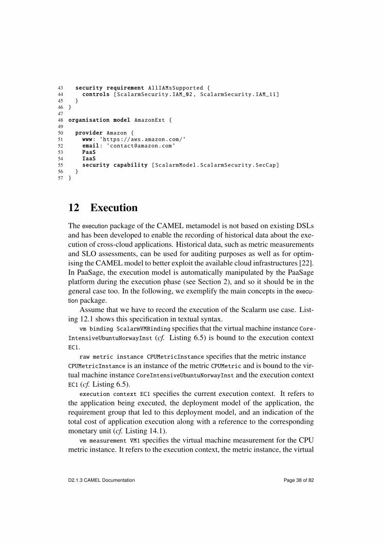
43 security requirement AllIAMsSupported {44 controls [ScalarmSecurity.IAM_02, ScalarmSecurity.IAM_11]45 }46 }4748 organisation model AmazonExt {4950 provider Amazon {51 www: ’https://aws.amazon.com/’52 email: ’[email protected]’53 PaaS
54 IaaS
55 security capability [ScalarmModel.ScalarmSecurity.SecCap]56 }57 }
12 ExecutionThe execution package of the CAMEL metamodel is not based on existing DSLsand has been developed to enable the recording of historical data about the exe-cution of cross-cloud applications. Historical data, such as metric measurementsand SLO assessments, can be used for auditing purposes as well as for optim-ising the CAMEL model to better exploit the available cloud infrastructures [22].In PaaSage, the execution model is automatically manipulated by the PaaSageplatform during the execution phase (see Section 2), and so it should be in thegeneral case too. In the following, we exemplify the main concepts in the execu-tion package.
Assume that we have to record the execution of the Scalarm use case. List-ing 12.1 shows this specification in textual syntax.vm binding ScalarmVMBinding specifies that the virtual machine instance Core-
IntensiveUbuntuNorwayInst (cf. Listing 6.5) is bound to the execution contextEC1.raw metric instance CPUMetricInstance specifies that the metric instance
CPUMetricInstance is an instance of the metric CPUMetric and is bound to the vir-tual machine instance CoreIntensiveUbuntuNorwayInst and the execution contextEC1 (cf. Listing 6.5).execution context EC1 specifies the current execution context. It refers to
the application being executed, the deployment model of the application, therequirement group that led to this deployment model, and an indication of thetotal cost of application execution along with a reference to the correspondingmonetary unit (cf. Listing 14.1).vm measurement VM1 specifies the virtual machine measurement for the CPU
metric instance. It refers to the execution context, the metric instance, the virtual
D2.1.3 CAMEL Documentation Page 38 of 82

machine instance (cf. Listing 6.5), the measured value (95.0), and the timestampof the measurement.
Similar to the vm measurement, the assessment A1 specifies the assessmentfor the CPU metric SLO. It comprises the appropriate reference, the indicationthat the SLO has been violated, and the timestamp of the assessment.
Listing 12.1: Scalarm execution model1 metric model ScalarmMetric {23 vm binding ScalarmVMBinding {4 execution context: ScalarmExecution.EC15 vm instance: ScalarmModel.ScalarmDeployment.
CoreIntensiveUbuntuNorwayInst6 }78 raw metric instance CPUMetricInstance {9 metric: ScalarmModel.ScalarmMetric.CPUMetric
10 sensor: ScalarmMetric.CPUSensor11 binding: ScalarmModel.ScalarmMetric.ScalarmVMBinding12 }13 }1415 execution model ScalarmExecution {1617 execution context EC1 {18 application: ScalarmModel.ScalarmApplication19 deployment model: ScalarmModel.ScalarmDeployment20 requirement group: ScalarmRequirement.ScalarmRequirementGroup21 total cost: 100.022 cost unit: ScalarmModel.ScalarmUnits.Euro23 }2425 vm measurement VM1 {26 execution context: ScalarmExecution.EC127 metric instance: ScalarmMetric.RawCPUMetricInstance28 vm instance: ScalarmModel.ScalarmDeployment.
CoreIntensiveUbuntuNorwayInst29 value: 95.030 time: 2016-10-31 T 22:5031 }3233 assessment A1 {34 execution context: ScalarmExecution.EC135 measurement: ScalarmExecution.VM136 slo: ScalarmRequirement.CPUMetricSLO37 violated
38 time: 2016-10-31 T 22:5039 }40 }
D2.1.3 CAMEL Documentation Page 39 of 82
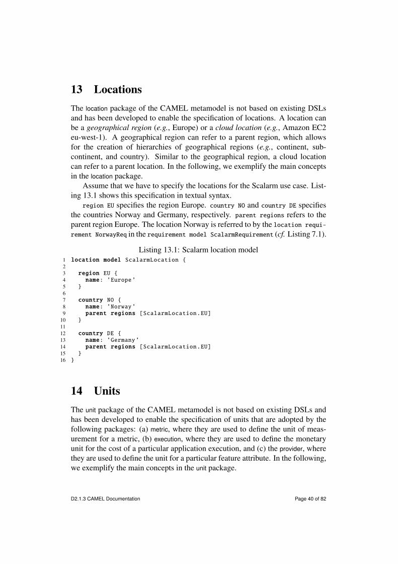
13 LocationsThe location package of the CAMEL metamodel is not based on existing DSLsand has been developed to enable the specification of locations. A location canbe a geographical region (e.g., Europe) or a cloud location (e.g., Amazon EC2eu-west-1). A geographical region can refer to a parent region, which allowsfor the creation of hierarchies of geographical regions (e.g., continent, sub-continent, and country). Similar to the geographical region, a cloud locationcan refer to a parent location. In the following, we exemplify the main conceptsin the location package.
Assume that we have to specify the locations for the Scalarm use case. List-ing 13.1 shows this specification in textual syntax.region EU specifies the region Europe. country NO and country DE specifies
the countries Norway and Germany, respectively. parent regions refers to theparent region Europe. The location Norway is referred to by the location requi-rement NorwayReq in the requirement model ScalarmRequirement (cf. Listing 7.1).
Listing 13.1: Scalarm location model1 location model ScalarmLocation {23 region EU {4 name: ’Europe’5 }67 country NO {8 name: ’Norway’9 parent regions [ScalarmLocation.EU]
10 }1112 country DE {13 name: ’Germany’14 parent regions [ScalarmLocation.EU]15 }16 }
14 UnitsThe unit package of the CAMEL metamodel is not based on existing DSLs andhas been developed to enable the specification of units that are adopted by thefollowing packages: (a) metric, where they are used to define the unit of meas-urement for a metric, (b) execution, where they are used to define the monetaryunit for the cost of a particular application execution, and (c) the provider, wherethey are used to define the unit for a particular feature attribute. In the following,we exemplify the main concepts in the unit package.
D2.1.3 CAMEL Documentation Page 40 of 82

Assume that we have to specify the units of the Scalarm use case. List-ing 14.1 shows this specification in textual syntax.
The unit model ScalarmUnit encompasses seven units that are referred to bymetrics in the metric model ScalarmMetric (cf. Listing 8.2). The specification ofeach unit follows the pattern: <unit_class> <unit_name>: <unit_type>. For in-stance, monetary unit {Euro: EUROS} specifies a monetary unit named “euros”and typed EUROS).
Listing 14.1: Scalarm unit model1 unit model ScalarmUnit {2 monetary unit {Euro: EUROS}3 throughput unit {SimulationsPerSecondUnit: TRANSACTIONS_PER_SECOND}4 time interval unit {ResponseTimeUnit: MILLISECONDS}5 time interval unit {ExperimentMakespanInSecondsUnit: SECONDS}6 transaction unit {NumberOfSimulationsLeftInExperimentUnit:
TRANSACTIONS}7 dimensionless {AvailabilityUnit: PERCENTAGE}8 dimensionless {CPUUnit: PERCENTAGE}9 }
The complete list of available units is a follows:
• core unit, which represents the unit of CPU cores
• monetary unit, which represents a monetary unit (e.g., EUROS)
• request unit, which represents the unit of number requests
• storage unit, which represents the unit of storage (e.g., BYTES)
• throughput unit, which represents the unit of throughput (e.g., REQUESTS-_PER_SECOND)
• time interval unit, which represents the unit of time interval (e.g., SE-CONDS)
• transaction unit, which represents the number of transactions
• dimensionless, which represents a unit without dimension (e.g., a unit ofPERCENTAGE is dimensionless)
15 TypesThe type package of the CAMEL metamodel is also based on Saloon [32, 33, 34].It provides the concepts to specify value types and values used across CAMEL
D2.1.3 CAMEL Documentation Page 41 of 82

models (e.g., integer, string, or enumeration). In the following, we exemplify themain concepts in the type package.
Assume that we have to specify the types of the Scalarm use case. List-ing 15.1 shows this specification in textual syntax.range Range0_100 specifies an integer range between 0 and 99 (i.e., 100, not
included). It is referred to by the metric CPUMetric (cf. Listing 8.2).range Range0_1000 specifies an integer range between 1 (i.e., 0, not included)
and 1000. It is referred to by the metric ResponseTimeMetric (cf. Listing 8.2).range DoubleRange0_100 specifies a double range between 0.0 and 100.0. It
is referred to by the metric AvailabilityMetric (cf. Listing 8.2).The other value types, enumerations, and lists in the type model SINTEFType
are referred to by the features in the provider model SINTEFProvider Availability-Metric (cf. Listing 10.1).
Listing 15.1: Scalarm type model1 type model ScalarmType {23 range Range0_100 {4 primitive type: IntType5 lower limit {int value 0 included}6 upper limit {int value 100}7 }89 range Range0_10000 {
10 primitive type: IntType11 lower limit {int value 0}12 upper limit {int value 10000 included}13 }1415 range DoubleRange0_100 {16 primitive type: DoubleType17 lower limit {double value 0.0 included}18 upper limit {double value 100.0 included}19 }20 }2122 type model SINTEFType {2324 string value type StringValueType {25 primitive type: StringType26 }2728 enumeration VMTypeEnum {29 values [ ’M1.MICRO’ : 0, ..., ’M1.LARGE’ : 4, ..., ’C1.XXLARGE’ :
15 ]30 }3132 enumeration VMOSEnum {33 values [ ’Fedora 20 server x86_64’ : 0, ’Ubuntu 14.04 LTS Server
x86_64’ : 1, ... ]34 }3536 list StorageList {
D2.1.3 CAMEL Documentation Page 42 of 82

37 values [ int value 0, int value 20, int value 40, int value 80,int value 160 ]
38 }3940 list MemoryList {41 values [ int value 256, int value 512, int value 2048, int value
4096, int value 8192, int value 16384, int value 32768 ]42 }4344 list CoresList {45 values [ int value 1, int value 2, int value 4, int value 8, int
value 16 ]46 }47 }
16 Java APIs and CDOAs mentioned, CAMEL consists of an Ecore model (cf. Section 5). This en-ables to specify CAMEL models using the CAMEL Textual Editor as well as toprogrammatically manipulate and persist them through Java APIs.
Listing 16.1 shows the creation of a VM of Scalarm (cf. Section 2). Theclasses that are instantiated and initialised in the code have been automaticallygenerated by the EMF generator model based on the deployment package. Allclass instances are obtained using the DeploymentFactory object specific for thedeployment package. This object provides a set of methods that are used to makesure the model objects are appropriately instantiated.
Listing 16.1: A sample VM definition//create a ML VMVM coreIntensiveVM = DeploymentFactory.eINSTANCE.createVM();//First create VM requirement set & add it to the deployment modelVMRequirementSet coreIntensiveReqs = DeploymentFactory.eINSTANCE.
createVMRequirementSet();mlReqs.setName("CoreIntensiveReqs");coreIntensiveVM.setVmRequirementSet(coreIntensiveReqs);sensAppDeploymentModel.getVmRequirementSets().add(coreIntensiveReqs);//Create a quantitative hardware requirement to include it in the
requirement setQuantitativeHardwareRequirement coreIntensiveRequirment =
RequirementFactory.eINSTANCE.createQuantitativeHardwareRequirement();
coreIntensiveRequirment.setName("CoreIntensive");coreIntensiveRequirment.setMaxCores(32);coreIntensiveRequirment.setMinCores(8);coreIntensiveRequirment.setMaxRAM(8192);coreIntensiveRequirment.setMinRAM(4096);rm.getRequirements().add(coreIntensiveRequirment);coreIntensiveReqs.setQuantitativeHardwareRequirement(
coreIntensiveRequirment);//Create a LOcation requirement imposing that the VM should be located
in Scotland
D2.1.3 CAMEL Documentation Page 43 of 82
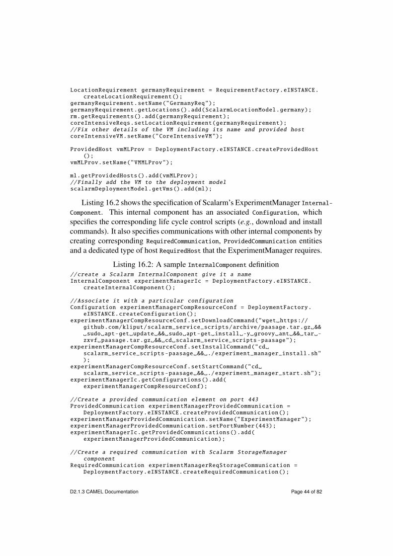
LocationRequirement germanyRequirement = RequirementFactory.eINSTANCE.createLocationRequirement();
germanyRequirement.setName("GermanyReq");germanyRequirement.getLocations().add(ScalarmLocationModel.germany);rm.getRequirements().add(germanyRequirement);coreIntensiveReqs.setLocationRequirement(germanyRequirement);//Fix other details of the VM including its name and provided hostcoreIntensiveVM.setName("CoreIntensiveVM");
ProvidedHost vmMLProv = DeploymentFactory.eINSTANCE.createProvidedHost();
vmMLProv.setName("VMMLProv");
ml.getProvidedHosts().add(vmMLProv);//Finally add the VM to the deployment modelscalarmDeploymentModel.getVms().add(ml);
Listing 16.2 shows the specification of Scalarm’s ExperimentManager Internal-Component. This internal component has an associated Configuration, whichspecifies the corresponding life cycle control scripts (e.g., download and installcommands). It also specifies communications with other internal components bycreating corresponding RequiredCommunication, ProvidedCommunication entitiesand a dedicated type of host RequiredHost that the ExperimentManager requires.
Listing 16.2: A sample InternalComponent definition//create a Scalarm InternalComponent give it a nameInternalComponent experimentManagerIc = DeploymentFactory.eINSTANCE.
createInternalComponent();
//Associate it with a particular configurationConfiguration experimentManagerCompResourceConf = DeploymentFactory.
eINSTANCE.createConfiguration();experimentManagerCompResourceConf.setDownloadCommand("wget https://
github.com/kliput/scalarm_service_scripts/archive/paasage.tar.gz && sudo apt-get update && sudo apt-get install -y groovy ant && tar -zxvf paasage.tar.gz && cd scalarm_service_scripts -paasage");
experimentManagerCompResourceConf.setInstallCommand("cd scalarm_service_scripts -paasage && ./experiment_manager_install.sh");
experimentManagerCompResourceConf.setStartCommand("cd scalarm_service_scripts -paasage && ./experiment_manager_start.sh");
experimentManagerIc.getConfigurations().add(experimentManagerCompResourceConf);
//Create a provided communication element on port 443ProvidedCommunication experimentManagerProvidedCommunication =
DeploymentFactory.eINSTANCE.createProvidedCommunication();experimentManagerProvidedCommunication.setName("ExperimentManager");experimentManagerProvidedCommunication.setPortNumber(443);experimentManagerIc.getProvidedCommunications().add(
experimentManagerProvidedCommunication);
//Create a required communication with Scalarm StorageManagercomponent
RequiredCommunication experimentManagerReqStorageCommunication =DeploymentFactory.eINSTANCE.createRequiredCommunication();
D2.1.3 CAMEL Documentation Page 44 of 82

experimentManagerReqStorageCommunication.setIsMandatory(true);experimentManagerReqStorageCommunication.setName("
ExperimentManager_consumes_SotrageManager");experimentManagerReqStorageCommunication.setPortNumber(20001);experimentManagerIc.getRequiredCommunications().add(
experimentManagerReqStorageCommunication);
//Create a required host elementRequiredHost coreIntensiveUbuntuGermanyHostReq = DeploymentFactory.
eINSTANCE.createRequiredHost();coreIntensiveUbuntuGermanyHostReq.setName("
coreIntensiveUbuntuGermanyHostReq");experimentManagerIc.setRequiredHost(coreIntensiveUbuntuGermanyHostReq)
;
//Finally add the component to the deployment modelscalarmDeploymentModel.getInternalComponents().add(experimentManagerIc
);
Listing 16.3 shows the creation of a Communication binding between the Scal-arm’s ExperimentManager and the Scalarm’s StorageManager.
Listing 16.3: A sample Communication definition//Create communication by also specifying its name and the provided
and required communicationsCommunication experimentManagerToStorageManager = DeploymentFactory.
eINSTANCE.createCommunication();experimentManagerToStorageManager.setName("
experimentManagerToStorageManager");experimentManagerToStorageManager.setProvidedCommunication(
storageManagerProvidedCommunicationMongodNnginx);experimentManagerToStorageManager.setRequiredCommunication(
experimentManagerReqStorageCommunication);
//Add communication to deployment modelscalarmDeploymentModel.getCommunications().add(
experimentManagerToStorageManager);
Listing 16.4 shows the specification of a Hosting binding between the Experi-mentManager InternalComponent and the VM of coreIntensiveUbuntuGermanyHosttype.
Listing 16.4: A sample Hosting definition//Create hosting, specify its name and the required and provided hostsHosting experimentManagerToCoreIntensiveUbuntuGermany =
DeploymentFactory.eINSTANCE.createHosting();experimentManagerToCoreIntensiveUbuntuGermany.setName("
ExperimentManagerToCoreIntensiveUbuntuGermany");experimentManagerToCoreIntensiveUbuntuGermany.setProvidedHost(
coreIntensiveUbuntuGermanyHost);experimentManagerToCoreIntensiveUbuntuGermany.setRequiredHost(
coreIntensiveUbuntuGermanyHostReq);
//Add hosting to the deployment modelscalarmDeploymentModel.getHostings().add(
experimentManagerToCoreIntensiveUbuntuGermany);
D2.1.3 CAMEL Documentation Page 45 of 82

Listing 16.5 shows the process of saving a deployment model in a CDO re-pository. As mentioned, CDO uses a set of APIs that are designed after the JDBCAPIs. In order to save a model, we first need to create a session and obtain atransaction over it. This example adopts a local database that is accessed using aTCP connector from the Net4j framework20, a partner project used within CDO.Once the transaction is obtained, the deployment model refers to the CDOResourceresponsible for its persistence, and the transaction is committed.
Listing 16.5: Saving a deployment model in a CDO repository//initialize and activate a containerfinal IManagedContainer container = ContainerUtil.createContainer();Net4jUtil.prepareContainer(container);TCPUtil.prepareContainer(container);// CDONet4jUtil.prepareContainer(container);container.activate();
// create a Net4j TCP connectorfinal IConnector connector = (IConnector) TCPUtil.getConnector(
container , "localhost:2036");
// create the session configurationCDONet4jSessionConfiguration config = CDONet4jUtil.
createNet4jSessionConfiguration();config.setConnector(connector);config.setRepositoryName("repo1");
// create the actual session with the repositoryCDONet4jSession cdoSession = config.openNet4jSession();
// obtain a transaction objectCDOTransaction transaction = cdoSession.openTransaction();
// create a CDO resource objectCDOResource resource = transaction.getOrCreateResource("/
scalarmResource1");EObject camelModel = ScalarmModel.createScalarmModel();
// associate the deployment model to the resourceresource.getContents().add(camelModel);
// commit the transaction to persist the modeltransaction.commit();
Listing 16.6 shows the process of loading and modifying a deployment model.In this example, the host VM for the ExperimentManager is changed. We change itby setting the ProvidedHost of the Hosting to point to a virtual machine definitionsuitable for single CPU intensive tasks (assuming it is initially one suited formulti-core processing).
Listing 16.6: Loading and modifying a deployment model in a CDO repository
20https://www.eclipse.org/modeling/emf/?project=net4j
D2.1.3 CAMEL Documentation Page 46 of 82

// open a new transactionCDOTransaction transaction = cdoSession.openTransaction();
// load the existing resource of SensApp and get the top-most modelwhich is a deployment one
CDOResource resource = transaction.getResource("/scalarmResource1");assertTrue(resource.getContents().get(0) instanceof DeploymentModel);DeploymentModel model = (DeploymentModel) resource.getContents().get
(0);
// get provided host for the CPU intensive virtual machine (which wewant to change to)
ProvidedHost CPUIntensiveProvidedHost = null;for(VM vm: model.getVMs()){if (vm.getName().equals("CPUIntensiveUbuntuGermany")){
CPUIntensiveProvidedHost = vm.getProvidedHost();break;
}}
// find the current hosting in the deployment modelHosting currentHosting = null;for (Hosting h2: model.getHostings()){if (h2.getName().equals("
ExperimentManagerToCoreIntensiveUbuntuGermany")){currentHosting = h2;break;
}}
// modify hosting in the deployment model and replace the currentprovided host (which is presumably "CoreIntensiveUbuntuGermany")
currentHosting.setName("ExperimentManagerToCPUIntensiveUbuntuGermany");
currentHosting.setProvidedHost(CPUIntensiveProvidedHost);
// commit the transaction to persist the updated modeltransaction.commit();
The example above show the Java code for programmatically saving, load-ing, and modifying part of a deployment model in a CDO repository. The Javacode for programmatically saving, loading, and modifying models from otherpackages of the CAMEL metamodel is analogous. The full version of the Javacode of the Scalarm example is available for reference in the Git repository atOW2.21
17 Related WorkIn the following, we compare CAMEL with related work. We distinguish betweentools (e.g., DevOps and cloud orchestration tools) to automate the deployment
21https://github.com/groundnuty/scalarm-paasage-camel/tree/master/model_in_java/src/main/java/eu/paasage/camel/agh
D2.1.3 CAMEL Documentation Page 47 of 82

of cloud applications and languages to model cloud aspects. For the latter cat-egory, we define six comparison criteria and evaluate the languages according tothese criteria. This comparison will validate our claim that CAMEL advancesthe state-of-the-art in modelling and execution of cloud applications.
17.1 ToolsIn the cloud community, libraries such as jclouds22 or DeltaCloud23 provide gen-eric APIs abstracting over the heterogeneous APIs of IaaS providers. These lib-raries reduce the cost and e↵ort of deploying cloud applications and can be usedby the platforms supporting CAMEL. For instance, the PaaSage platform usesjclouds.
DevOps tools such as Puppet24 or Chef25 rely on scripting languages to spe-cify the deployment of cloud applications. These tools increase the automationin deploying cloud applications. However, the deployment scripts cannot betreated as deployment models, which introduces a mismatch between the de-ployment topology of cloud applications and the technique used to representthem.
Cloud orchestration tools such as Cloudify26 or Apache Brooklyn27 rely onthe TOSCA [31] (see below) to specify the topologies of cloud applicationsalong with the processes for their orchestration. These tools facilitate the provi-sioning, deployment, and monitoring of cloud applications across multiple cloudinfrastructures [2]. However, TOSCA does not provide an instance model andhence does not support models@run-time, which makes these tools unsuitablefor reasoning on the models and hence enabling self-adaptive cross-cloud ap-plications.
17.2 LanguagesIn the research community, within the Reservoir28 EU project, Galán et al. [15]proposed a service specification language for cloud computing platforms, whichextends the DMTF’s Open Virtualization Format (OVF) standard to address thespecific requirements of these environments.
22http://www.jclouds.org23http://deltacloud.apache.org/24https://puppetlabs.com/25http://www.opscode.com/chef/26http://getcloudify.org/27https://brooklyn.apache.org/28http://www.reservoir-fp7.eu/
D2.1.3 CAMEL Documentation Page 48 of 82
Within the 4CaaSt29 EU project, Nguyen et al. [26] proposed a language tospecify Blueprint Templates—a uniform abstract description for cloud serviceo↵erings that may cross di↵erent cloud computing layers, i.e., infrastructure andplatform.
The MODAClouds project30 provides a family of DSLs collectively calledMODACloudML. MODACloudML relies on the following three layers of ab-straction: (i) the cloud-enabled computation independent model (CCIM) to de-scribe an application and its data, (ii) the CPIM (as in PaaSage) to describeconcerns of cloud applications in a cloud-agnostic way, and (iii) the CPSM (asin PaaSage) to describe concerns of cloud applications in a cloud-specific way,so that they can be provisioned and deployed on specific clouds.
The ARTIST project31 provides the Cloud Application Modelling Language(CAML). CAML consists of an internal DSL [14] realised as a UML libraryalong with UML profiles [4] rather than an external DSL such as CAMEL. Themain rationale behind the latter stems from the goal of the ARTIST project tosupport the migration of existing applications to the cloud, whereby UML mod-els are reverse-engineered and tailored to a selected cloud environment.
The ARCADIA project32 provides a methodology and a framework to sup-port the development of highly-distributed applications (HDAs) that are recon-figurable by design. The ARCADIA Framework [36] relies on unikernel tech-nology in order to bundle microservices, and leverages on an extensible contextmodel throughout the entire life cycle of HDAs. Similar to CAMEL, the AR-CADIA Context Model [16] has multiple facets, such as the component model,the service graph model, the service deployment model, and the service run-timemodel.
In the standards community, the Topology and Orchestration Specificationfor Cloud Applications (TOSCA) [31] is a specification developed by the OASISconsortium, which provides a language for specifying the components compris-ing the topology of cloud applications along with the processes for their orches-tration.
17.3 ComparisonIn the following, we define six comparison criteria and evaluate the aforemen-tioned languages according to these criteria. These criteria were selected to eval-uate the usefulness, usability, and self-adaptation support of the lanugages. In
29http://www.4caast.eu30http://www.modaclouds.eu/31http://www.artist-project.eu/32http://www.arcadia-framework.eu
D2.1.3 CAMEL Documentation Page 49 of 82

particular, the abstract syntax and aspect coverage, delivery model support, andmodels@run-time support reflect the usefulness of the language; the concretesyntax and integration level reflect the usability; and models@run-time supportalso reflects the self-adaptation support.
Abstract syntax. The abstract syntax of a language describes the set of con-cepts, their attributes, and their relations, as well as the rules for combiningthese concepts to specify valid statements that conform to this abstract syntax.The abstract syntax can be defined using formalisms that provide di↵erent cap-abilities. For instance, XML Schema are more suitable for tree-based structures,while MOF-based formalisms are more suitable for graph-based structures ando↵er better tool support and better integration with constraint languages such asOCL. This criterion is used to identify which formalisms are used by a language.The values for this criterion are “XML Schema” and “MOF”.33
Concrete syntax. The concrete syntax of a language describes the textual orgraphical notation that renders the concepts of the abstract syntax, their attrib-utes, and their relations. The concrete syntax can be defined using notations thatprovide a trade-o↵ between the intuitiveness and the e↵ectiveness of the syntax.For instance, a textual syntax may be less intuitive but more e↵ective than a cor-responding graphical syntax. This criterion is used to identify which notationsare supported by a language. The values for this criterion can be “XML”, “txt”(textual), and “gra” (graphical).
Aspect coverage. A language may cover multiple aspects within the same do-main or across multiple domains. For instance, in CAMEL we specify the lifecycle of cross-cloud applications using 11 aspects, namely deployment, require-ment, location, metric, scalability, provider, organisation, security, execution,unit, and type. This criterion reflects how many of these aspects are covered bya language. The values for this criterion can be “low” if it covers at most threeaspects, “medium” if it covers at most six aspects, and “high” otherwise.
Integration level. A language that covers multiple aspects may provide dif-ferent levels of integration across these aspects, especially when these aspectsinclude similar or equivalent concepts. The integration solution has to: (a) joinequivalent concepts and separate similar concepts into respective sub-concepts;(b) homogenise the remaining concepts so that they are defined at the same levelof granularity; (c) enforce a uniform formalism and notation for the abstract and
33Abstract syntaxes defined in Ecore fall into this category.
D2.1.3 CAMEL Documentation Page 50 of 82

concrete syntaxes; and (d) enforce the consistency, correctness, and integrity ofthe models. Each of these steps is a precondition to the following step and re-quires an increasing amount of e↵ort. This criterion reflects how many of thesesteps have been adopted to integrate the sub-languages. The values for this cri-terion can be “low” if the sub-languages were integrated following only step(a), “medium” if they were integrated following steps (a) and (b), “high” if theywere integrated following all steps, and “N/A” if they were not integrated. Inthe last case, each sub-language covers one aspect and is independent from theother sub-languages. This independence leads to the following disadvantages:(a) it raises the complexity of the language, since each sub-language has its ownabstract and concrete syntax; (b) it steepens the learning curve and increases themodelling e↵ort for the same reason; (d) it leads to the duplication of model-ling for similar or equivalent concepts; (e) it leads to the manual validation ofcross-aspect dependencies.
Delivery model support. A cross-cloud application may exploit any of thecloud delivery models, namely IaaS and PaaS. A language for specifying the lifecycle of cross-cloud applications should support concepts for each of these clouddelivery models. This criterion reflects how many of these delivery models aresupported by a language. The values for this criterion can be “IaaS” and “PaaS”.
Models@run-time support. Models@run-time [5] provides an abstract rep-resentation of the underlying running system, whereby a modification to themodel is enacted on-demand in the system, and a change in the system is auto-matically reflected in the model. Models@run-time can be implemented usingthe type-instance pattern [1], which facilitates reusability and abstraction. Forinstance, we implemented the type-instance pattern in two aspects, namely de-ployment and metric. In the case of deployment, this allows to automaticallyadapt the component- and virtual machine instances in the deployment modelbased on scalability rules (e.g., scale out a Scalarm service along with the under-lying virtual machine). In the case of monitoring, this allows to automaticallypopulate the metric model with metric instances (e.g., CPU load measurementsof the virtual machine hosting the Scalarm service). This criterion reflects howmany of these aspects implement the type-instance pattern. The values for thiscriterion can be “deployment” and “metric”.
17.4 AnalysisTable 1 shows the comparison of the languages based on the criteria above.CAMEL scores best in all criteria apart from the last one.
D2.1.3 CAMEL Documentation Page 51 of 82
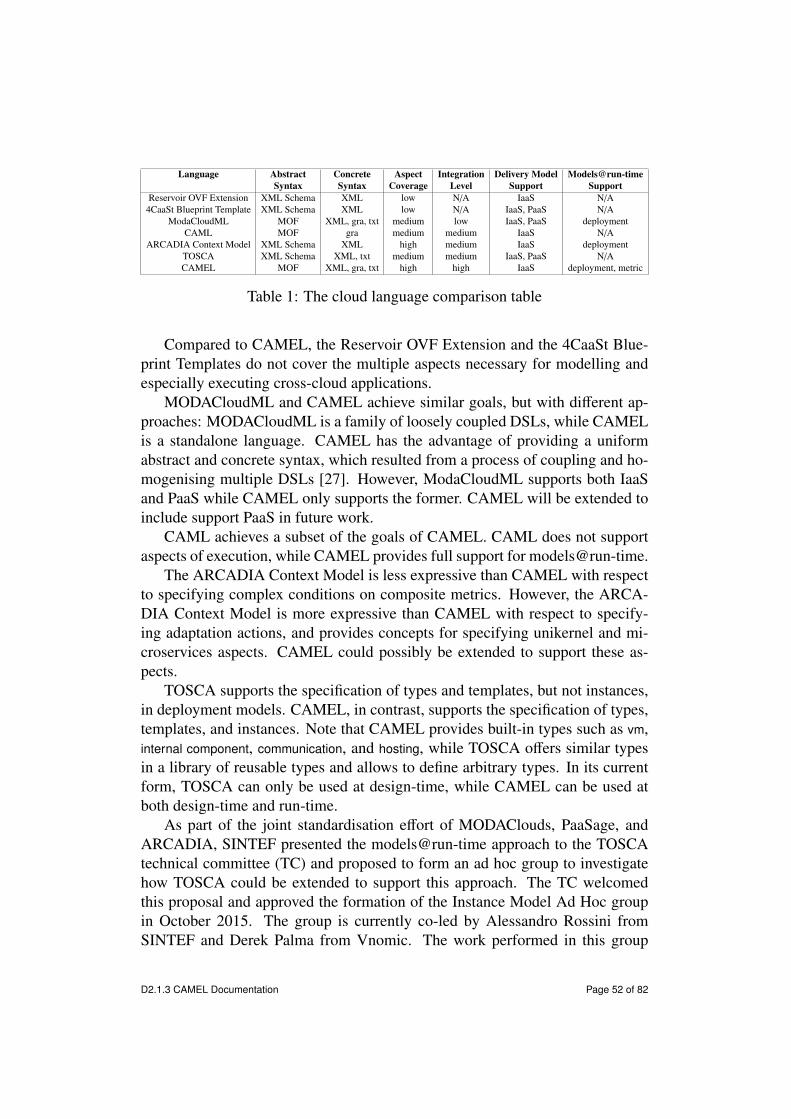
Language Abstract Concrete Aspect Integration Delivery Model Models@run-timeSyntax Syntax Coverage Level Support Support
Reservoir OVF Extension XML Schema XML low N/A IaaS N/A4CaaSt Blueprint Template XML Schema XML low N/A IaaS, PaaS N/A
ModaCloudML MOF XML, gra, txt medium low IaaS, PaaS deploymentCAML MOF gra medium medium IaaS N/A
ARCADIA Context Model XML Schema XML high medium IaaS deploymentTOSCA XML Schema XML, txt medium medium IaaS, PaaS N/ACAMEL MOF XML, gra, txt high high IaaS deployment, metric
Table 1: The cloud language comparison table
Compared to CAMEL, the Reservoir OVF Extension and the 4CaaSt Blue-print Templates do not cover the multiple aspects necessary for modelling andespecially executing cross-cloud applications.
MODACloudML and CAMEL achieve similar goals, but with di↵erent ap-proaches: MODACloudML is a family of loosely coupled DSLs, while CAMELis a standalone language. CAMEL has the advantage of providing a uniformabstract and concrete syntax, which resulted from a process of coupling and ho-mogenising multiple DSLs [27]. However, ModaCloudML supports both IaaSand PaaS while CAMEL only supports the former. CAMEL will be extended toinclude support PaaS in future work.
CAML achieves a subset of the goals of CAMEL. CAML does not supportaspects of execution, while CAMEL provides full support for models@run-time.
The ARCADIA Context Model is less expressive than CAMEL with respectto specifying complex conditions on composite metrics. However, the ARCA-DIA Context Model is more expressive than CAMEL with respect to specify-ing adaptation actions, and provides concepts for specifying unikernel and mi-croservices aspects. CAMEL could possibly be extended to support these as-pects.
TOSCA supports the specification of types and templates, but not instances,in deployment models. CAMEL, in contrast, supports the specification of types,templates, and instances. Note that CAMEL provides built-in types such as vm,internal component, communication, and hosting, while TOSCA o↵ers similar typesin a library of reusable types and allows to define arbitrary types. In its currentform, TOSCA can only be used at design-time, while CAMEL can be used atboth design-time and run-time.
As part of the joint standardisation e↵ort of MODAClouds, PaaSage, andARCADIA, SINTEF presented the models@run-time approach to the TOSCAtechnical committee (TC) and proposed to form an ad hoc group to investigatehow TOSCA could be extended to support this approach. The TC welcomedthis proposal and approved the formation of the Instance Model Ad Hoc groupin October 2015. The group is currently co-led by Alessandro Rossini fromSINTEF and Derek Palma from Vnomic. The work performed in this group
D2.1.3 CAMEL Documentation Page 52 of 82

will guarantee that the contribution of CAMEL will partly be integrated into thestandard.
18 Conclusion and Future WorkCAMEL allows to specify multiple aspects of cross-cloud applications, suchas provisioning, deployment, service level, monitoring, scalability, providers,organisations, users, roles, security, and execution. It supports models@run-time, which enables reasoning on CAMEL models and hence managing self-adaptive cross-cloud applications.
In this document, we described the design and implementation of CAMEL.Moreover, we provided a real-world running example to illustrate how to specifymodels in a concrete textual syntax and how to programmatically manipulate andpersist them through Java APIs. Finally, we described the abstract syntax of thelanguage.
In the future, we will continue to develop CAMEL iteratively. In particular,we will adapt and extend the capabilities of CAMEL to the changing require-ments. In this respect, the developers will provide feedback on whether theconcepts in CAMEL are adequate to design and implement their components.Similarly, the users will provide feedback on whether the concepts in CAMELare satisfactory for modelling the use cases. In addition to the PaaSage project,CAMEL has been adopted by the CACTOS34, CloudSocket35, and MUSA36 pro-jects. This will guarantee the further development and validation of CAMEL ina wide variety of cloud computing scenarios.
In addition, CAMEL models that conform to an old version of CAMEL oftenhave to be migrated to conform to its current version. In the future, we wouldlike to integrate a solution for the challenge of maintaining multiple versions andautomatically migrating CAMEL models [27] based on CDO and Edapt.
Finally, we will contribute to the Instance Model Ad Hoc group of TOSCAso that the contribution of CAMEL will partly be integrated into the standard.
Acknowledgements. The research leading to these results was supported bythe European Commission’s Seventh Framework Programme (FP7/2007-2013)under grant agreement number 317715 (PaaSage) and the European Commis-sion’s Framework Programme Horizon 2020 (ICT-07-2014) under grant agree-ment numbers 644690 (CloudSocket) and 645372 (ARCADIA). The authorswould like to thank the use case providers and component developers in the
34http://www.cactosfp7.eu/35https://www.cloudsocket.eu36http://www.musa-project.eu/
D2.1.3 CAMEL Documentation Page 53 of 82
above projects for the constructive feedback on CAMEL. Michal Orzechowskiis also grateful to AGH University of Science and Technology for their supportunder grant number 15.11.230.212.
References[1] Colin Atkinson and Thomas Kühne. ‘Rearchitecting the UML infrastruc-
ture’. In: ACM Transactions on Modeling and Computer Simulation 12.4(2002), pp. 290–321. doi: 10.1145/643120.643123.
[2] Daniel Baur, Daniel Seybold, Frank Griesinger, Athanasios Tsitsipas, Chris-topher B. Hauser and Jörg Domaschka. ‘Cloud Orchestration Features:Are Tools Fit for Purpose?’ In: UCC 2015: 8th IEEE/ACM InternationalConference on Utility and Cloud Computing. Ed. by Ioan Raicu, Omer F.Rana and Rajkumar Buyya. IEEE Computer Society, 2015, pp. 95–101.isbn: 978-0-7695-5697-0. doi: 10.1109/UCC.2015.25.
[3] David Benavides, Sergio Segura and Antonio Ruiz Cortés. ‘Automatedanalysis of feature models 20 years later: A literature review’. In: Inf.Syst. 35.6 (2010), pp. 615–636. doi: 10.1016/j.is.2010.01.001.
[4] Alexander Bergmayr, Javier Troya, Patrick Neubauer, Manuel Wimmerand Gerti Kappel. ‘UML-based Cloud Application Modeling with Lib-raries, Profiles, and Templates’. In: CloudMDE 2014: 2nd InternationalWorkshop on Model-Driven Engineering on and for the Cloud. Ed. byRichard F. Paige, Jordi Cabot, Marco Brambilla, Louis M. Rose and JamesH. Hill. Vol. 1242. CEUR Workshop Proceedings. CEUR, 2014, pp. 56–65. url: http://ceur-ws.org/Vol-1242/paper7.pdf.
[5] Gordon S. Blair, Nelly Bencomo and Robert B. France. ‘[email protected]’.In: IEEE Computer 42.10 (2009), pp. 22–27. doi: 10.1109/MC.2009.326.
[6] Jörg Domaschka, Daniel Baur, Daniel Seybold and Frank Griesinger. ‘Cloud-iator: A Cross-Cloud, Multi-Tenant Deployment and Runtime Engine’.In: SummerSOC 2015: 9th Workshop and Summer School On Service-Oriented Computing 2015. 2015.
[7] Jörg Domaschka, Frank Griesinger, Daniel Baur and Alessandro Rossini.‘Beyond Mere Application Structure: Thoughts on the Future of CloudOrchestration Tools’. In: Procedia Computer Science 68 (2015). CloudForward 2015: 1st International Conference on Cloud Forward: FromDistributed to Complete Computing, pp. 151–162. issn: 1877-0509. doi:10.1016/j.procs.2015.09.231.
D2.1.3 CAMEL Documentation Page 54 of 82
[8] Jörg Domaschka, Kyriakos Kritikos and Alessandro Rossini. ‘Towards aGeneric Language for Scalability Rules’. In: Advances in Service-Orientedand Cloud Computing—Workshops of ESOCC 2014. Ed. by GuadalupeOrtiz and Cuong Tran. Vol. 508. Communications in Computer and In-formation Science. Springer, 2015, pp. 206–220. isbn: 978-3-319-14885-4. doi: 10.1007/978-3-319-14886-1_19.
[9] Jörg Domaschka, Daniel Seybold, Frank Griesinger and Daniel Baur. ‘Axe:A Novel Approach for Generic, Flexible, and Comprehensive Monitoringand Adaptation of Cross-Cloud Applications’. In: Advances in Service-Oriented and Cloud Computing—Workshops of ESOCC 2015. Ed. by Ant-onio Celesti and Philipp Leitner. Vol. 567. Communications in Computerand Information Science. Springer, 2016, pp. 184–196. isbn: 978-3-319-33312-0. doi: 10.1007/978-3-319-33313-7_14.
[10] Jörg Domaschka et al. D5.1.2—Product Executionware. PaaSage projectdeliverable. Sept. 2015.
[11] Nicolas Ferry, Franck Chauvel, Alessandro Rossini, Brice Morin and ArnorSolberg. ‘Managing multi-cloud systems with CloudMF’. In: NordiCloud2013: 2nd Nordic Symposium on Cloud Computing and Internet Techno-logies. Ed. by Arnor Solberg, Muhammad Ali Babar, Marlon Dumas andCarlos E. Cuesta. ACM, 2013, pp. 38–45. isbn: 978-1-4503-2307-9. doi:10.1145/2513534.2513542.
[12] Nicolas Ferry, Alessandro Rossini, Franck Chauvel, Brice Morin and ArnorSolberg. ‘Towards model-driven provisioning, deployment, monitoring,and adaptation of multi-cloud systems’. In: CLOUD 2013: 6th IEEE In-ternational Conference on Cloud Computing. Ed. by Lisa O’Conner. IEEEComputer Society, 2013, pp. 887–894. isbn: 978-0-7695-5028-2. doi: 10.1109/CLOUD.2013.133.
[13] Nicolas Ferry, Hui Song, Alessandro Rossini, Franck Chauvel and ArnorSolberg. ‘CloudMF: Applying MDE to Tame the Complexity of Man-aging Multi-Cloud Applications’. In: UCC 2014: 7th IEEE/ACM Interna-tional Conference on Utility and Cloud Computing. Ed. by Randall Bilof.IEEE Computer Society, 2014, pp. 269–277. doi: 10.1109/UCC.2014.36.
[14] Martin Fowler. Domain-Specific Languages. Addison-Wesley Professional,2010. isbn: 978-0321712943.
[15] Fermín Galán, Américo Sampaio, Luis Rodero-Merino, Irit Loy, VictorGil and Luis Miguel Vaquero. ‘Service specification in cloud environ-ments based on extensions to open standards’. In: COMSWARE 2009: 4th
D2.1.3 CAMEL Documentation Page 55 of 82

International Conference on COMmunication System softWAre and Mid-dlewaRE. Ed. by Jan Bosch and Siobhán Clarke. ACM, 2009, 19:1–19:12.isbn: 978-1-60558-353-2. doi: 10.1145/1621890.1621915.
[16] Panagiotis Gouvas et al. D2.2—Definition of the ARCADIA Context Model.ARCADIA project deliverable. July 2015.
[17] Thomas R. Gruber. ‘A translation approach to portable ontology specific-ations’. In: Knowledge Acquisition 5.2 (June 1993), pp. 199–220. issn:1042-8143. doi: 10.1006/knac.1993.1008.
[18] Keith Je↵ery, Nikos Houssos, Brigitte Jörg and Anne Asserson. ‘Researchinformation management: the CERIF approach’. In: IJMSO 9.1 (2014),pp. 5–14. doi: 10.1504/IJMSO.2014.059142.
[19] Kyo C. Kang, Sholom G. Cohen, James A. Hess, William E. Novak andA. Spencer Peterson. Feature-Oriented Domain Analysis (FODA)—FeasibilityStudy. Tech. rep. The Software Engineering Institute, 1990. url: http://www.sei.cmu.edu/reports/90tr021.pdf.
[20] Kyriakos Kritikos, Jörg Domaschka and Alessandro Rossini. ‘SRL: AScalability Rule Language for Multi-Cloud Environments’. In: CloudCom2014: 6th IEEE International Conference on Cloud Computing Techno-logy and Science. Ed. by Juan E. Guerrero. IEEE Computer Society, 2014,pp. 1–9. isbn: 978-1-4799-4093-6. doi: 10.1109/CloudCom.2014.170.
[21] Kyriakos Kritikos, Tom Kirkham, Bartosz Kryza and Philippe Massonet.‘Security Enforcement for Multi-Cloud Platforms—The Case of PaaS-age’. In: Procedia Computer Science 68 (2015). Cloud Forward 2015: 1stInternational Conference on Cloud Forward: From Distributed to Com-plete Computing, pp. 103–115. issn: 1877-0509. doi: 10.1016/j.procs.2015.09.227.
[22] Kyriakos Kritikos, Kostas Magoutis and Dimitris Plexousakis. ‘TowardsKnowledge-Based Assisted IaaS Selection’. In: CloudCom 2016: 8th IEEEInternational Conference on Cloud Computing Technology and Science.IEEE Computer Society, 2016.
[23] Dariusz Król and Jacek Kitowski. ‘Self-scalable services in service ori-ented software for cost-e↵ective data farming’. In: Future GenerationComp. Syst. 54 (2016), pp. 1–15. doi: 10.1016/j.future.2015.07.003.
[24] Thomas Kühne. ‘Matters of (meta-)modeling’. In: Software and SystemsModeling 5.4 (2006), pp. 369–385. doi: 10.1007/s10270-006-0017-9.
D2.1.3 CAMEL Documentation Page 56 of 82
[25] Peter Mell and Timothy Grance. The NIST Definition of Cloud Com-puting. Special Publication 800-145. National Institute of Standards andTechnology, Sept. 2011.
[26] Dinh Khoa Nguyen, Francesco Lelli, Yehia Taher, Michael Parkin, MikeP. Papazoglou and Willem-Jan van den Heuvel. ‘Blueprint Template Sup-port for Engineering Cloud-Based Services’. In: ServiceWave 2011: 4thEuropean Conference Towards a Service-Based Internet. Ed. by WitoldAbramowicz, Ignacio Martín Llorente, Mike Surridge, Andrea Zismanand Julien Vayssière. Vol. 6994. Lecture Notes in Computer Science. Springer,2011, pp. 26–37. isbn: 978-3-642-24754-5. doi: 10.1007/978-3-642-24755-2_3.
[27] Nikolay Nikolov, Alessandro Rossini and Kyriakos Kritikos. ‘Integrationof DSLs and Migration of Models: A Case Study in the Cloud Comput-ing Domain’. In: Procedia Computer Science 68 (2015). Cloud Forward2015: 1st International Conference on Cloud Forward: From Distributedto Complete Computing, pp. 53–66. issn: 1877-0509. doi: 10.1016/j.procs.2015.09.223.
[28] Object Management Group. Object Constraint Language. 2.4. http://www.omg.org/spec/OCL/2.4/. Feb. 2014.
[29] Object Management Group. Unified Modeling Language Specification.2.4.1. http://www.omg.org/spec/UML/2.4.1/. Aug. 2011.
[30] Object Management Group. XML Metadata Interchange Specification.2.4.2. http://www.omg.org/spec/XMI/2.4.2/. Apr. 2014.
[31] Derek Palma and Thomas Spatzier. Topology and Orchestration Specific-ation for Cloud Applications (TOSCA). Tech. rep. Organization for theAdvancement of Structured Information Standards (OASIS), June 2013.url: http://docs.oasis-open.org/tosca/TOSCA/v1.0/cos01/TOSCA-v1.0-cos01.pdf.
[32] Clément Quinton, Nicolas Haderer, Romain Rouvoy and Laurence Duch-ien. ‘Towards multi-cloud configurations using feature models and on-tologies’. In: MultiCloud 2013: International Workshop on Multi-cloudApplications and Federated Clouds. ACM, 2013, pp. 21–26. isbn: 978-1-4503-2050-4. doi: 10.1145/2462326.2462332.
[33] Clément Quinton, Daniel Romero and Laurence Duchien. ‘Cardinality-based feature models with constraints: a pragmatic approach’. In: SPLC2013: 17th International Software Product Line Conference. Ed. by To-moji Kishi, Stan Jarzabek and Stefania Gnesi. ACM, 2013, pp. 162–166.isbn: 978-1-4503-1968-3. doi: 10.1145/2491627.2491638.
D2.1.3 CAMEL Documentation Page 57 of 82

[34] Clément Quinton, Romain Rouvoy and Laurence Duchien. ‘LeveragingFeature Models to Configure Virtual Appliances’. In: CloudCP 2012:2nd International Workshop on Cloud Computing Platforms. ACM, 2012,pp. 21–26. isbn: 978-1-4503-1161-8. doi: 10.1145/2168697.2168699.
[35] Alessandro Rossini. ‘Cloud Application Modelling and Execution Lan-guage (CAMEL) and the PaaSage Workflow’. In: Advances in Service-Oriented and Cloud Computing—Workshops of ESOCC 2015. Ed. by Ant-onio Celesti and Philipp Leitner. Vol. 567. Communications in Computerand Information Science. Springer, 2016, pp. 437–439. isbn: 978-3-319-33313-7. doi: 10.1007/978-3-319-33313-7.
[36] Alessandro Rossini, Franck Chauvel, Panagiotis Gouvas, Anastasios Za-feiropoulos, Costantinos Vassilakis and Eleni Fotopoulou. D3.1a—SmartController Reference Implementation. ARCADIA project deliverable. Apr.2016.
[37] Alessandro Rossini, Kiriakos Kritikos, Nikolay Nikolov, Jörg Domaschka,Frank Griesinger, Daniel Seybold and Daniel Romero. D2.1.3—CAMELDocumentation. PaaSage project deliverable. Oct. 2015.
[38] Alessandro Rossini, Adrian Rutle, Yngve Lamo and Uwe Wolter. ‘A form-alisation of the copy-modify-merge approach to version control in MDE’.In: Journal of Logic and Algebraic Programming 79.7 (2010), pp. 636–658. doi: 10.1016/j.jlap.2009.10.003.
Appendix A Abstract SyntaxAs mentioned, the CAMEL metamodel is organised into packages, wherebyeach package reflects an aspect (or domain).
Figure 5 shows the top-level camel package of the CAMEL metamodel. ACamelModel consists of an Application along with a collection of sub-models, namelyDeploymentModels (see Section A.1), RequirementModels (see Section A.2), Met-ricModels (see Section A.3), ScalabilityModels (see Section A.3), ProviderModels(see Section A.5), OrganisationModels (see Section A.4), SecurityModels (see Sec-tion A.6), ExecutionModels (see Section A.7), LocationModels (see Section A.8),UnitModels (see Section A.9), and TypeModels (see Section A.10).
An Application (see Figure 6) represents a cross-cloud application. It refers toan Owner, which represents the entity of an organisation that owns the applica-tion. Moreover, it refers to one or more DeploymentModels, which represent thetopology of the application along with the commands to handle its life cycle.
D2.1.3 CAMEL Documentation Page 58 of 82

camel
CamelModelApplication
name : EStringversion : EStringdescription : EString
deployment
DeploymentModel
execution
ExecutionModel
location
LocationModel
metric
MetricModel
organisation
OrganisationModel
provider
ProviderModel
requirement
RequirementModel
scalability
ScalabilityModel
security
SecurityModel
type
TypeModel
unit
UnitModel
[0..*] applications
[0..*] deploymentModels
[0..*] executionModels
[0..*] locationModels
[0..*] metricModels
[0..*] organisationModels
[0..*] providerModels
[0..*] requirementModels [0..*] scalabilityModels
[0..*] typeModels
[0..*] securityModels
[0..*] unitModels
[0..*] applications
[0..*] deploymentModels
Figure 5: The class diagram of the CAMEL metamodel including packages
The properties version and description represent the version (or revision) and de-scription of the application, respectively.
A.1 DeploymentFigure 6 shows the type part of the class diagram of the deployment package. ADeploymentModel (omitted for brevity) is a collection of DeploymentElements. Adeployment element can be a Component, a Communication, or a Hosting. A deploy-ment element can refer to Configurations, which represent sets of commands tohandle the life cycle of the deployment element.
A Component (see Figure 6) represents a reusable type of application compon-ent. A component can be an InternalComponent or a VM (short for virtual machine).
A VMRequirementSet represents a set of requirements for virtual machines, i.e.hardware requirements, operating system requirements, location requirements,and image requirements (see Section A.2). It can be referred to by a virtual ma-chine or by a deployment model. In the former case, the set of requirementsapplies to all instances of the virtual machine, whereas in the latter case, the set
D2.1.3 CAMEL Documentation Page 59 of 82

Communication
type : CommunicationType = ANY
CommunicationPort
portNumber : EInt = 0
Component
DeploymentElement
name : EString
Hosting
HostingPort
InternalComponent
ProvidedCommunication ProvidedHost RequiredHost
VMVMRequirementSet
name : EString
RequiredCommunication
isMandatory : EBoolean = false
[1..1] providedCommunication
[0..*] providedCommunications [0..*] providedHosts
[1..1] providedHost [1..1] requiredHost
[0..*] compositeInternalComponents
[0..1] requiredHost
[0..1] vmRequirementSet
[1..1] requiredCommunication
[0..*] requiredCommunications
Figure 6: Part of the class diagram of the deployment package related to deploy-ment types
of requirements applies to all instances of all virtual machines within a deploy-ment model.
A CommunicationPort (see Figure 6) represents a communication port of anapplication component. A communication port can be a ProvidedCommunication,meaning that it provides a feature to another component, or a RequiredCommunic-ation, meaning that it consumes a feature from another component. The propertyisMandatory of RequiredCommunication represents that the component depends onthe feature provided by another component.
A HostingPort (see Figure 6) represents a containment port of a component.A hosting port can be a ProvidedHost, meaning that it provides an execution en-vironment to another component (e.g., a virtual machine provides an executionenvironment to a servlet container, and a servlet container provides an executionenvironment to a servlet), or a RequiredHost, meaning that a component consumesan execution environment from another component.
A Communication represents a reusable type of communication binding betweena required and a provided communication port. The property type of Communic-ation specifies that the components at each end of the communication can bedeployed on any virtual machine instance(s) (value ANY, default); the compon-ents must be deployed on the same virtual machine instance (value LOCAL);the components must be deployed on separate virtual machine instances (valueREMOTE).
A Hosting represents a reusable type of hosting binding between a required
D2.1.3 CAMEL Documentation Page 60 of 82

and a provided host port.The types presented above can be instantiated in order to form a CPSM.
A.2 RequirementsFigure 7 shows the part of the class diagram of the requirement package related toits main concepts.
HardRequirement
Requirement
name : EString
RequirementGroup
requirementOperator : RequirementOperatorType = AND
RequirementModel
SoftRequirement
priority : EDouble = 0.0
[1..*] requirements
[0..*] requirements
Figure 7: Part of the class diagram of the requirement package related to its mainconcepts
A RequirementModel is a collection of Requirements. A requirement can be aHardRequirement, such as a service level objective (SLO) (e.g., response time <100ms), meaning that it is measurable and must be satisfied, or a SoftRequire-ment, such as an optimisation objective (e.g., maximise performance), meaningthat it is not measurable. The property priority of SoftRequirement represents thepriority of the soft requirements. These priorities can be used to rank these softrequirements when reasoning on the application and generating a new CPSMfor it. They must be specified in the scale from 0.0 to 1.0 and the respective softrequirements could refer to metrics that are generated based on normalisationfunctions also taking values from 0.0 to 1.0.
A RequirementGroup represents a logical group of requirements, which can becomprised of single requirements or other requirement groups. The property re-quirementOperator of RequirementGroup represents the logical operator that is usedto connect these requirements and can be assigned values AND (logical conjunc-tion) or OR (logical disjunction). A requirement group refers to an Application forwhich the requirements must be satisfied. Note that a requirement group shouldnot contain conflicting requirements, such as scale requirements that are of thesame type and that refer to the same component.
A requirement group allows for the creation of a requirement tree, whichrepresents a tree of logically connected requirements that must be satisfied. Forinstance, a top-level requirement group (e.g., identified by the name Global) could
D2.1.3 CAMEL Documentation Page 61 of 82

contain two or more requirement groups logically connected by the OR operator.Each of the latter requirement groups (e.g., identified by the name Alternativei)could in turn contain single requirements, such as SLOs, logically connected bythe AND operator.
A.2.1 Hardware, OS & Image and Provider RequirementsFigure 8 shows the part of the class diagram of the requirement package related tohardware, OS, image, and provider requirements.
HardRequirement
LocationRequirement
Location
id : EString
ImageRequirement
imageId : EString
OSOrImageRequirement
OSRequirement
os : EStringis64os : EBoolean = true
ProviderRequirement
QualitativeHardwareRequirement
minBenchmark : EDouble = 0*0maxBenchmark : EDouble = 0*0
QuantitativeHardwareRequirement
minCPU : EDouble maxCPU : EDouble minCores : EInt maxCores : EInt minRAM : EInt maxRAM : EIntminStorage : EIntmaxStorage : EInt
HardwareRequirement
CloudProvider
public : EBoolean = falseSaaS : EBoolean = falsePaaS : EBoolean = falseIaaS : EBoolean = false
[1**p] locations[1**p] providers
Figure 8: Part of the class diagram of the requirement package related to hardware,OS, image, and provider requirements
HardwareRequirement, OsOrImageRequirement, and ProviderRequirement are hardrequirements. They can be referred to by a VMRequirementSet (see Section A.1).
A HardwareRequirement can be specialised into a QualitativeHardwareRequire-ment, which represents a requirement on the performance of a virtual machineinstance, or a QuantitativeHardwareRequirement, which represents a requirement onthe virtual hardware of a virtual machine. The properties min- and maxBenchmarkof QualitativeHardwareRequirement represent the range of benchmark results that avirtual machine instance must satisfy. The properties of QuantitativeHardwareRe-quirement represent the ranges of: CPU frequency, number of CPU cores, size ofRAM, and size of storage that a virtual machine instance must satisfy. Note thatfor at least one of these properties, at least one of the minimum and maximumbounds must be specified.
D2.1.3 CAMEL Documentation Page 62 of 82

An OsOrImageRequirement can be specialised into an OSRequirement, whichrepresents a requirement on the operating system run by a virtual machine, ora ImageRequirement, which represents a requirement on the image deployed ona virtual machine. The property os of OSRequirement represents the requiredoperating system (e.g., “Ubuntu” or “Windows”), while the property is64os rep-resents whether the operating system must be compiled for 64-bit architectures(e.g., x86-64). The property imageId of ImageRequirement represents the identifierof the required image.
A ProviderRequirement represents the set of cloud providers that must be con-sidered for an application deployment (e.g., Amazon and Rackspace only).
A LocationRequirement refers to one or more Locations (see Section A.8), whichrepresent either geographical regions (e.g., a continent, a country, or a region)or cloud locations (i.e., a location specific to a cloud provider) that must beconsidered for an application deployment (e.g., Germany only).
A.2.2 Service Level Objectives and OptimisationRequirements
Figure 9 shows the part of the class diagram of the requirement package related toSLOs and optimisation requirements.
OptimisationRequirement
optimisationFunction : OptimisationFunctionType = MINIMISE
ServiceLevelObjective
HardRequirement
Metric
description : EStringvalueDirection : EShort = 0layer : LayerType = SaaS
Condition
name : EStringcomparisonOperator : ComparisonOperatorType = GREATER_THANthreshold : EDouble = 0.0validity : EDate
SoftRequirement
priority : EDouble = 0.0
[0..1] metric[1..1] customServiceLevel
Figure 9: Part of the class diagram of the requirement package related to SLOsand optimisation requirements
A ServiceLevelObjective is a hard requirement. It refers to a Condition, suchas MetricCondition (see Section A.3), which represents the metric condition thatmust be satisfied (i.e., the corresponding measurement values must not cross aparticular threshold).
An OptimisationRequirement is a soft requirement. It refers to a Metric or a Prop-erty (see Section A.3), which represents the metric or the property, respectively,
D2.1.3 CAMEL Documentation Page 63 of 82

that should be optimised. Moreover, it refers to an Application or InternalCompon-ent, which represents the application or component, respectively, for which themetric should be optimised. The property optimisationFunction of OptimisationRe-quirement represents the optimisation function applied to the metric and can beassigned values MINIMISE or MAXIMISE.
A.2.3 Scale RequirementsFigure 10 shows the part of the class diagram of the requirement package relatedto scaling requirements.
HardRequirement
HorizontalScaleRequirement
minInstances : EInt = 0maxInstances : EInt = 0
ScaleRequirement
VerticalScaleRequirement
minCPU : EDouble = 0.0maxCPU : EDouble = 0.0minCores : EInt = 0maxCores : EInt = 0minRAM : EInt = 0maxRAM : EInt = 0minStorage : EInt = 0maxStorage : EInt = 0
InternalComponent VM
[1..1] component [1..1] vm
Figure 10: Part of the class diagram of the requirement package related to scalingrequirements
A ScaleRequirement is a hard requirement. It can be referred to by a Scalab-ilityRule (see Section A.3), which restrains which scaling actions are performed.A ScaleRequirement can be a HorizontalScaleRequirement, which represents the min-imum and maximum amount of instances allowed for a component, so that scale-out and scale-in actions will not exceed these bounds. Alternatively, it can be aVerticalScaleRequirement, which represents the minimum and maximum values al-lowed for virtual machine properties (e.g., number of CPU cores), so that scale-up and scale-down actions will not exceed these bounds. Note that for horizontalscale requirements, the maximum number of instances should be either -1 (in-finite) or greater or equal to the respective minimum amount. Minimum andmaximum values must be specified for at least one virtual machine property.
A.2.4 Security RequirementsFigure 11 shows the part of the class diagram of the requirement package relatedto location and security requirements.
D2.1.3 CAMEL Documentation Page 64 of 82
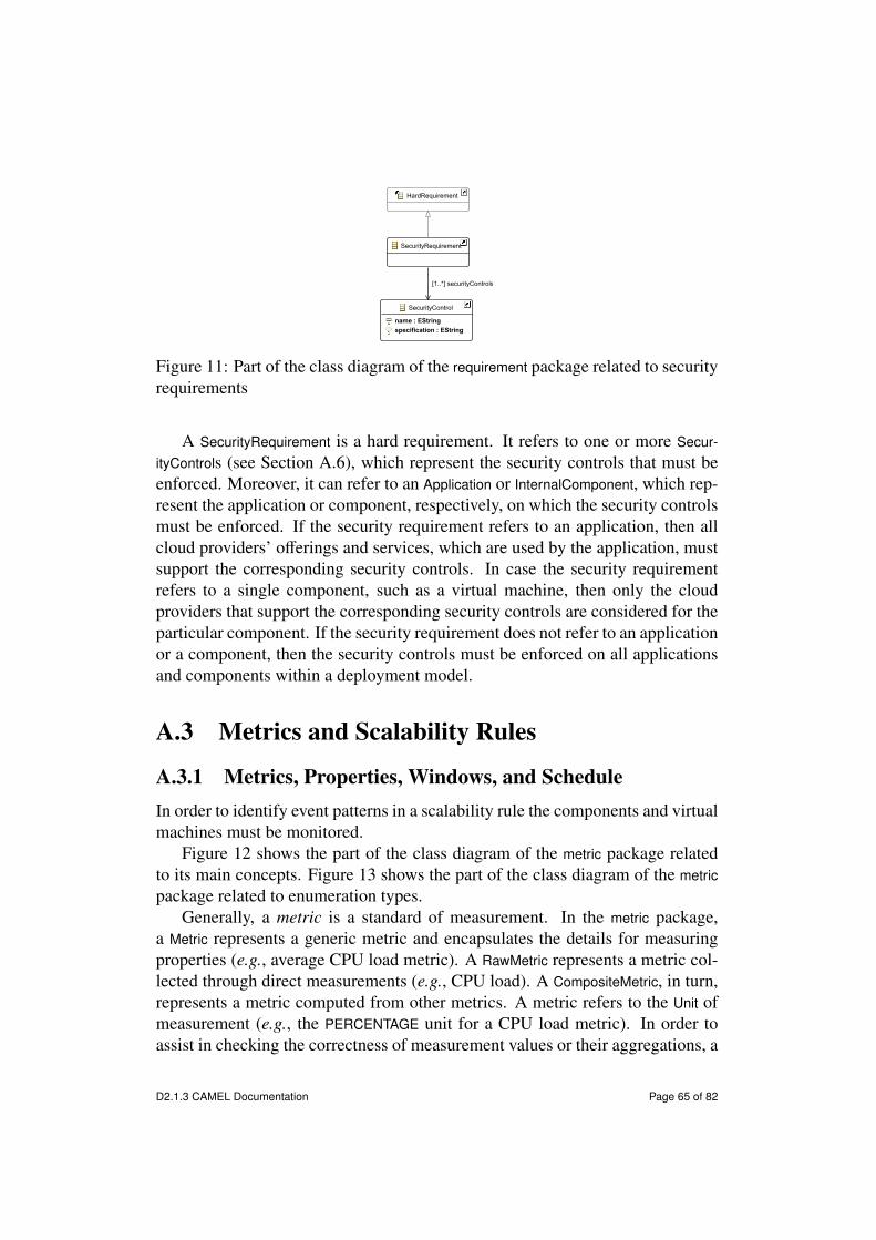
HardRequirement
SecurityRequirement
SecurityControl
name : EStringspecification : EString
[1..*] securityControls
Figure 11: Part of the class diagram of the requirement package related to securityrequirements
A SecurityRequirement is a hard requirement. It refers to one or more Secur-ityControls (see Section A.6), which represent the security controls that must beenforced. Moreover, it can refer to an Application or InternalComponent, which rep-resent the application or component, respectively, on which the security controlsmust be enforced. If the security requirement refers to an application, then allcloud providers’ o↵erings and services, which are used by the application, mustsupport the corresponding security controls. In case the security requirementrefers to a single component, such as a virtual machine, then only the cloudproviders that support the corresponding security controls are considered for theparticular component. If the security requirement does not refer to an applicationor a component, then the security controls must be enforced on all applicationsand components within a deployment model.
A.3 Metrics and Scalability Rules
A.3.1 Metrics, Properties, Windows, and ScheduleIn order to identify event patterns in a scalability rule the components and virtualmachines must be monitored.
Figure 12 shows the part of the class diagram of the metric package relatedto its main concepts. Figure 13 shows the part of the class diagram of the metricpackage related to enumeration types.
Generally, a metric is a standard of measurement. In the metric package,a Metric represents a generic metric and encapsulates the details for measuringproperties (e.g., average CPU load metric). A RawMetric represents a metric col-lected through direct measurements (e.g., CPU load). A CompositeMetric, in turn,represents a metric computed from other metrics. A metric refers to the Unit ofmeasurement (e.g., the PERCENTAGE unit for a CPU load metric). In order toassist in checking the correctness of measurement values or their aggregations, a
D2.1.3 CAMEL Documentation Page 65 of 82

Metric
description : EStringvalueDirection : EShort = 0layer : LayerType = SaaS
CompositeMetric
MetricFormulaParameter
name : EString
Property
name : EStringdescription : EStringtype : PropertyType = ABSTRACT
RawMetric
MetricFormula
function : MetricFunctionType = PLUSfunctionArity : MetricFunctionArityType = UNARYfunctionPattern : FunctionPatternType = MAP
Sensor
name : EStringconfiguration : EStringisPush : EBoolean = false
SingleValue
MetricModel
[1..1] property
[0..*] subProperties
[1..1] formula
[1..*] parameters
[0..*] sensors
[0..1] value
[0..*] metrics
[0..*] properties
[0..*] parameters
[0..*] sensors
Figure 12: Part of the class diagram of the metric package related to its mainconcepts
ComparisonOperatorType
GREATER_THANGREATER_EQUAL_THANLESS_THANLESS_EQUAL_THANEQUALNOT_EQUAL
FunctionPatternType
MAPREDUCE
MetricFunctionArityType
UNARYBINARYN_ARY
MetricFunctionType
PLUSMINUSTIMESDIVMODULOMEANSTDCOUNTMINMAXPERCENTILEDERIVATIVEMODEMEDIAN
PropertyType
ABSTRACTMEASURABLE
QuantifierType
ANYALLSOME
ScheduleType
FIXED_RATEFIXED_DELAYSINGLE_EVENT
WindowSizeType
MEASUREMENTS_ONLY
FIRST_MATCHBOTH_MATCH
WindowType
FIXEDSLIDING
TIME_ONLY
Figure 13: Part of the class diagram of the metric package related to enumerationtypes
metric also refers to a ValueType, which represents the range of values the metricis allowed to take.
Each CompositeMetric refers to a MetricFormula, which defines the computationused to derive this metric. For that purpose a MetricFormula refers to one or moreMetricFormulaParameters, which define the input for the formula. Further, it refersto a pre-defined function specifying the operation of the formula. There existthree types of parameters: constants, Metrics, or MetricFormulas. In the case ofconstants, the parameter refers to a Value. Thus, metric formulas can involve notonly constant values and other metrics but also calls to other metric formulas.
The MetricFunctionType represents the pre-defined function types, which in-
D2.1.3 CAMEL Documentation Page 66 of 82

clude mean (MEAN), standard deviation (STD), addition (ADD), subtraction (MI-NUS), division (DIV), and minimum (MIN). The function type restricts the numberof parameters, their order, and their kind. For instance, MEAN refers to one para-meter only, which should be of type metric or metric formula.
The FunctionPatternType classifies the strategy used to combine sets of metricinstances.
Any Metric also refers to a measurable Property, which represents the meas-ured non-functional property of a component or virtual machine. The propertytype represents the kind of property and can be assigned values MEASURABLE(the property can be measured directly) and ABSTRACT (the property cannot bemeasured and is reified by its sub-properties).
For instance, in the security domain, the incident management quality is aproperty that is realised at least by the concrete and measurable reporting cap-ability sub-property.
Figure 14 shows the part of the class diagram of the metric package related tometric instances.
MetricInstance
name : EString
CompositeMetricInstance
Metric
description : EStringvalueDirection : EShort = 0layer : LayerType = SaaS MetricContext
MetricObjectBinding
name : EString
RawMetricInstance
Schedule
name : EStringstart : EDateend : EDatetype : ScheduleType = FIXED_RATErepetitions : EInt = 0interval : ELong = 0
Window
name : EStringwindowType : WindowType = FIXEDsizeType : WindowSizeType = MEASUREMENTS_ONLYmeasurementSize : ELong = 0timeSize : ELong = 0
Sensor
name : EStringconfiguration : EStringisPush : EBoolean = false
MetricApplicationBinding MetricComponentBindingMetricVMBinding
[1..1] metric
[0..1] schedule
[0..1] window
[1..1] objectBinding
[0..1] metricContext
[1..*] composingMetricInstances
[1..1] metric
[0..1] window
[0..1] schedule
[1..1] sensor
Figure 14: Part of the class diagram of the metric package related to metric in-stances
Following the type-instance pattern, a MetricInstance represents a concretemetric which has been created in order to measure a property for a particular
D2.1.3 CAMEL Documentation Page 67 of 82

instance of a virtual machine or component. Metric instances follow the samespecialisation into raw and composite metric instances as metrics. The di↵eren-tiator between metric instances and metrics is that a MetricInstance has measuredvalues attached. For raw metric instances, this data corresponds to the timeseries generated by a sensor. The property configuration defines that sensor (e.g.,the name of the probe to be installed on a monitoring system). The propertyisPush defines whether the measured data will be pushed by the sensor or have tobe pulled by the run-time system.
The data associated with a composite metric instance CMI is computed fromthe data of other metric instances according to the computation specified by thecorresponding metric CM. It is important to note that from the descriptionsgiven so far, there exist multiple ways of creating composite metric instancesfrom a metric. The FunctionPatternType is used as demonstrated in the followingexample:
Assume we have a composite metric CM computed from a source metric Mc
using MEAN as the function type of the corresponding metric formula. This spe-cification can be interpreted in two ways: (i) for each metric instance associatedwith Mc, compute the average and map it to a composite metric instance; (ii)compute the average over all metric instances associated with Mc and computethe overall average. Using MAP as a function pattern type for CM realises case(i), mapping each metric instance of Mc to a new metric instance; using REDUCErealises case (ii), reducing a set of metric instances to a single instance.
Each MetricInstance refers to a particular sub-class of MetricObjectBinding: Met-ricComponentBinding, MetricVMBinding, MetricApplicationBinding. Bindings are usedby the run-time system to configure the monitoring system. A MetricComponent-Binding associates a particular component and respective application with a met-ric and requires the deployment of one or more sensors reporting measurementsfor this component. Similarly, the MetricVMBinding associates a virtual machinewith a metric. Finally, the MetricApplicationBinding associates the application as awhole with a metric. In this case, one or more sensors will have to be deployed tovirtual machines on which one or more component instances of this applicationhave been deployed to perform the respective measurements to be aggregated.
Windows and Schedules allow to further specify the way computations of com-posite metrics are performed.
Metric instances may refer to Windows, which represent how multiple meas-urements will be temporarily stored and used to perform computations for thisinstance. The window size may be defined by a time frame, a fixed number ofmeasurements, or both. In the last case, it may be su�cient to wait for eitherthe first property to be fulfilled, or for both. The property sizeType represents thestrategy to be used for this purpose. Finally, the property windowType, in turn,represents what happens when the window size is reached. SLIDING represents
D2.1.3 CAMEL Documentation Page 68 of 82

that the window is slid by dropping superfluous elements, while FIXED representsthat the window is cleared.
Metric instances may also refer to a Schedule, which represents any aspectof the operations/measurements that must be executed on a regular, timely basis(e.g., when an operation must run and when the scheduling must end). For acomposite metric instance, a schedule defines when and how often the instancewill be evaluated by applying the indirectly associated MetricFormula. For a rawmetric instance, a schedule defines how often its value is measured by the re-spective metric sensor. The property type represents whether successive runshappen at a fixed rate or with a fixed delay. Finally, the property intervalUnitrepresents the time unit used for the schedule interval.
A.3.2 Conditions and ContextsFigure 15 shows the part of the class diagram of the metric package related toconditions.
ConditionContext
name : EStringquantifier : QuantifierType = ANYminQuantity : EDouble = 0.0maxQuantity : EDouble = 0.0isRelative : EBoolean = false
MetricContextPropertyContext
Property
name : EStringdescription : EStringtype : PropertyType = ABSTRACT
Sensor
name : EStringconfiguration : EStringisPush : EBoolean = false
CompositeMetricContext
Metric
description : EStringvalueDirection : EShort = 0layer : LayerType = SaaS
RawMetricContext
Schedule
name : EStringstart : EDateend : EDatetype : ScheduleType = FIXED_RATErepetitions : EInt = 0interval : ELong = G
Window
name : EStringwindowType : WindowType = FIXEDsizeType : WindowSizeType = MEASUREMENTS_ONLYmeasurementSize : ELong = 0timeSize : ELong = 0
Condition
name : EStringcomparisonOperator : ComparisonOperatorType = GREATER_THANthreshold : EDouble = GUGvalidity : EDate
MetricConditionPropertyCondition
[1..1] property
[0..*] subProperties
[0..*] sensors
[1..1] metric
[0..1] window
[0..1] schedule
[0..*] composingMetricContexts
[1..1] property
[1..1] sensor
[1..1] metricContext[1..1] propertyContext
Figure 15: Part of the class diagram of the metric package related to conditions
A Condition represents an abstract condition with a threshold value. The prop-erty operator represents a comparison operator i.e., greater than or less than (in-cluding and excluding equality) as well as (in)equality. The property validitydefines for how long the condition will be valid. A condition enables to ex-press general requirements for cloud-based applications not tied to a particular
D2.1.3 CAMEL Documentation Page 69 of 82

deployment model. It also enables the expression of generic requirements thatmay hold for a CAMEL user irrespective of the applications. A condition can bespecialised into a MetricCondition or a PropertyCondition.
A MetricCondition represents a constraint imposed on a metric. A constraint isviolated when the comparison of the values of the instances of this metric withthe threshold of the condition using the metric’s operator is false. The violation of ametric condition will lead to the triggering of a simple, non-functional event an-d/or a violation of an SLO (which is reflected in the respective SLOAssessment—see Section A.7). Note that constraints are not expressed on metric instances buton metrics. This enables the re-use of metric conditions in di↵erent executioncontexts and guides the production of the instances of the metrics involved inthese conditions to enable the assessment of the conditions under the respectiveparticular execution contexts.
A PropertyCondition represents a condition on a property. Thus, it is possibleto specify constraints, e.g., on the cost for the whole application or for someof its components only. These constraints must be interpreted appropriately inorder to derive the required property values (e.g., based on a particular internalmetric used for producing the respective property value). As a property is notassociated with a specific unit, a property condition refers to a monetary unit(e.g., euros) and a time interval unit (e.g., seconds), which allows to assess thecost per time and not in absolute terms.
A condition, either pertaining to a metric or to a property, refers to a par-ticular ConditionContext, which represents the context under which the conditionshould hold. The context represents whether the condition must be enforced onthe whole application or a particular component/virtual machine. It also repres-ents for how many instances of the application or component/virtual machinethe condition must be checked. Two di↵erent types of quantification are distin-guished: relative and absolute. The qualifier relative represents the minimum andmaximum percentage of application or component/virtual machine instances onwhich the condition must hold. The qualifier absolute, in turn, represents the min-imum and maximum number of instances of an application or component/virtualmachine on which the condition must hold.
Four of the properties of ConditionContext allow to specify quantifications: (a)quantifier refers to a QuantifierType, which represents the set of instances to con-sider (all, any, some) in order to evaluate the condition—in the case of some,the constructs (b)–(c) can be used to further specify the type and limits of quan-tification; (b) isRelative defines whether a relative or absolute quantification isconcerned; (c) minQuantity represents the minimum relative or absolute value ofinstances; (d) maxQuantity represents the maximum relative or absolute value ofinstances.
Note that the CAMEL user must specify the correct minimum and maximum
D2.1.3 CAMEL Documentation Page 70 of 82

instance values in case the quantifier type is SOME: for absolute quantification,the maximum value should always be greater than or equal to the minimum oneunless it equals -1 (infinite) and both values should be integer-based, while, forrelative quantification, not only should the maximum value be greater or equalto the minimum one, but also both should be in the range [0.0,1.0].
Depending on which element is associated, i.e., metric or property, a Condi-tionContext is further specialised into a PropertyContext and MetricContext. A Proper-tyContext represents the context of the property to be measured and evaluated. AMetricContext represents the metric to be used in the evaluation of the condition.For composite metrics, CompositeMetricContext refers to the contexts of the com-posing metrics of the current metric. For raw metrics, RawMetricContext refers tothe sensor that produces the measurements of this metric.
A.3.3 Scalability RulesA ScalabilityRule refers to an Event and a set of Actions. The Event represents eithera single event or an event pattern that triggers the execution of the actions. TheActions can either specify which components and virtual machines are changed bythe scalability rule (i.e., in the case of scaling actions) and how or just remark thata global deployment decision has to be made (i.e., in the case of event creationactions, see next sub-section). A ScalabilityRule refers to a set of ScaleRequirementsthat restrict how scaling actions are performed. It also refers to Entities such asthe user or the organisation associated with the scalability rule (see Section A.4).
Note that the CAMEL user must not specify conflicting scale requirements(i.e., scale requirements of the same type which refer to the same internal com-ponent/virtual machine) or scaling actions which conflict with the scale require-ments posed. A scale action conflicts with a scale requirement in the followingtwo cases: (a) it is a HorizontalScalingAction, the requirement is of the respectivetype HorizontalScaleRequirement, and the amount of instances to scale-in or outdoes not conform with the range limit dictated by the requirement (i.e., amountis greater than the di↵erence between the upper and lower values in the rangelimit); (b) it is a VerticalScalingAction, the requirement is of the respective type Ver-ticalScaleRequirement and the update on a particular virtual machine characteristicis greater than the di↵erence between the upper and lower values in the rangelimit dictated by the requirement for this virtual machine characteristic.
A.3.4 ActionsFigure 16 shows the part of the class diagram of the scalability package related toactions.
D2.1.3 CAMEL Documentation Page 71 of 82

ScalingAction
Action
name : EStringtype : ActionType = CREATES
HorizontalScalingAction
count : EInt = 0
VerticalScalingAction
memoryUpdate : EInt = 0CPUUpdate : EDouble = 0.0coreUpdate : EInt = 0storageUpdate : EInt = 0ioUpdate : EInt = 0networkUpdate : EInt = 0
Figure 16: Part of the class diagram of the scalability package related to actions
An Action can be specialised into a ScalingAction. The ScalingAction, in turn,can be specialised into a HorizontalScalingAction or a VerticalScalingAction. The Hori-zontalScalingAction refers to a VM and an InternalComponent (both specified via thedeployment package). In case such an action is executed, the specified componentis scaled (out or in) along with the virtual machine hosting it. The property countdefines the number of additional instances to create, or the number of existing in-stances to destroy. In contrast to horizontal scaling, the VerticalScalingAction refersto a concrete VMInstance. The properties *Update define the amount of virtual re-sources (e.g., CPU cores, RAM, or storage) to be added to or removed from thevirtual machine instance.
Note that the CAMEL user must provide correct action types for the cor-responding actions. This means that HorizontalScalingActions must be mapped toaction types of either SCALE_IN or SCALE_OUT and VerticalScalingActions must bemapped to action types of either SCALE_UP or SCALE_DOWN.
A.3.5 EventsFigure 17 shows the part of the class diagram of the scalability package related toevents, while Figure 18 shows the portion related to enumeration types.
An Event can be specialised into a SimpleEvent or an EventPattern. The Sim-pleEvent, in turn, can be specialised into a FunctionalEvent or a NonFunctionalEvent.The FunctionalEvent represents a functional error (e.g., a virtual machine or a com-ponent has failed). The NonFunctionalEvent represents the violation of a metriccondition (e.g., the response time of a component exceeds the target responsetime in an SLO). The NonFunctionalEvent refers to a MetricCondition, which definesthe threshold for the metric.
An EventInstance represents the actual (measurement) data associated with aparticular event that occurred in the system (e.g., the actual measured value andthe component producing the event). The property status represents the status
D2.1.3 CAMEL Documentation Page 72 of 82

Event
name : EString
EventPatternSimpleEvent
FunctionalEvent
functionalType : EString
NonFunctionalEvent
isViolation : EBoolean = false
BinaryEventPattern
lowerOccurrenceBound : EInt = 0upperOccurrenceBound : EInt = 0operator : BinaryPatternOperatorType = AND
UnaryEventPattern
occurrenceNum : EInt = 0operator : UnaryPatternOperatorType = EVERY
EventInstance
name : EStringstatus : StatusType = CRITICALlayer : LayerType = SaaS
Timer
name : EStringtype : TimerType = WITHINtimeValue : EInt = 0maxOccurrenceNum : EInt = 0
TimeIntervalUnit
[0..1] leftEvent
[0..1] rightEvent
[1..1] event
[1..1] event
[0..1] timer
[1..1] unit
Figure 17: Part of the class diagram of the scalability package related to events
BinaryPatternOperatorType
ANDORXORPRECEDESREPEAT_UNTIL
StatusType
CRITICALWARNINGSUCCESSFATAL
TimerType
WITHINWITHIN_MAXINTERVAL
UnaryPatternOperatorType
EVERYNOTREPEATWHEN
Figure 18: Part of the class diagram of the scalability package related to enumer-ation types
of the event, i.e., if it is fatal, critical, warning, or success. This property canprovide useful insight (e.g., for performing an analysis on QoS) while also en-abling the evaluation/assessment of the events.
Events are grouped by EventPatterns, which can be specialised into BinaryEvent-Patterns or UnaryEventPatterns.
A BinaryEventPattern uses a binary operator to associate either two Events witheach other or one event with a Timer. The property operator can be set to one of thecommon, logical operators such as AND and OR, the order operator PRECEDES,and the occurrence operator REPEAT_UNTIL (see Figure 18). PRECEDES definesthat an event has to occur prior to another one. REPEAT_UNTIL defines that anevent has to occur multiple times until another event occurs. In this case, theCAMEL user should define the lower and/or upper bounds for the number ofevent occurrences.
A UnaryEventPattern refers to just one event along with a unary operator. Theproperty operator can be set to NOT, EVERY, REPEAT, and WHEN. NOT defines thatthe negation of an event must be considered. EVERY defines that every occur-
D2.1.3 CAMEL Documentation Page 73 of 82

rence of an event must be considered (e.g., to define that a scalability rule mustbe triggered every time an event A occurs and not just once). REPEAT defines thatan event has to occur multiple times. In this case, the CAMEL user must specifya value for the property occurrenceNum, which represents the number of eventoccurrences. WHEN defines that an event has to occur according to a particulartime constraint defined by a Timer.
A Timer represents a time constraint for an event pattern. The property typerepresents the kind of timer. WITHIN defines that an event has to occur withina particular time frame. WITHIN_MAX defines that an event has to occur withina particular time frame, but only up to a specific number of times. In this case,the CAMEL user must specify a value for the property maxOccurrenceNum, whichrepresents the maximum number of event occurrences. INTERVAL defines that anevent has to occur after a particular amount of time.
The following are two examples that illustrate the composition of events inevent patterns. (a) The condition A AND (B OR C) can be expressed as a Bin-aryEventPattern X1 that comprises the SimpleEvent A and another BinaryEventPatternX2 both connected by the AND operator. X2, in turn, comprises the two Sim-pleEvents B and C connected by the OR operator. (b) The condition that eitherA or three times B occurs within two minutes can be expressed as a UnaryEvent-Pattern U1 that comprises a BinaryEventPattern B1, the WHEN operator, and a Timerdefining a two minute threshold. B1, in turn, comprises the SimpleEvent A and aUnaryEventPattern U2 connected by the OR operator. Finally, U2 comprises justthe SimpleEvent B, the REPEAT operator, and a value of 3 for the property occur-renceNum.
A.4 OrganisationsFigure 19 shows the class diagram of the organisation package.
An Entity is a generic entity from CERIF. An entity can be an Organisation ora User.
An organisation can be specialised into a CloudProvider. The property publicrepresents whether the cloud provider is public or not, while the properties PaaS,IaaS and SaaS represent whether the cloud provider supports the correspondingservice models or not. A DataCenter represents a data centre of a cloud provider.The property codeName represents the internal code name used to identify thedata centre at the cloud provider (e.g., Amazon EC2 eu-west-1).
A user represents a person belonging to an organisation. It refers to PaaS-ageCredentials, which represent the credentials to authenticate a user in the PaaS-age platform. It can also refer to CloudCredentials, which represent the credentialsto authenticate and authorise the user in a cloud provider and hence enable per-
D2.1.3 CAMEL Documentation Page 74 of 82

AllowedActions
resource : EString
CloudCredentials
securityGroup : EStringpublicSSHKey : EStringprivateSSHKey : EString
CloudProvider
public : EBoolean = falseSaaS : EBoolean = falsePaaS : EBoolean = falseIaaS : EBoolean = false
Credentials
name : EString
DataCenter
name : EStringcodeName : EString
Entity
ExternalIdentifier
identifier : EStringdescription : EString
Organisation
name : EStringwww : EStringpostalAddress : EStringemail : EString
PaaSageCredentials
username : EStringpassword : EString
Permission
start : EDateend : EDate
Resource
ResourceGroup
name : EString/level : EInt = 0
Role
name : EString
RoleAssignment
name : EStringstart : EDateend : EDateassignedOn : EDate
User
name : EStringemail : EStringfirstName : EStringlastName : EStringwww : EString
UserGroup
name : EString[1..1] cloudProvider
[1..1] cloudProvider
[1..1] role
[1..1] resource
[1..]] resources
[0..1] user
[1..1] role
[0..1] userGroup
[0..]] externalIdentifiers
[0..]] cloudCredentials
[1..1] paasageCredentials
[1..]] users
Figure 19: The class diagram of the organisation package
forming tasks on behalf of the user on the cloud provider. A UserGroup representsa group of users.
A Role represents a role of a user or user group as in role-based access control(RBAC). A RoleAssignment represents the assignment of a role. It refers to eithera user or a user group. The property assignmentTime represents the timestamp ofthe role assignment, while the properties startTime and endTime represent the startand end timestamps of the validity of the role.
A Permission represents the set of actions allowed to be performed by a roleon a resource. It refers to Actions, which represent the actions themselves, andResourceFilters, which represent filters on the sets of resources on which actionsare performed. Filters can refer either to services (through a ServiceResourceFilterobject), or information (through an InformationResourceFilter object). The proper-ties startTime and endTime represent the start and end timestamps of the validityof the permission.
A.5 ProvidersFigure 20 shows the class diagram of the provider package.
A ProviderModel has a root Feature and a set of Constraints. A Feature has aFeature Cardinality. The properties min and max represent the lower and upper
D2.1.3 CAMEL Documentation Page 75 of 82
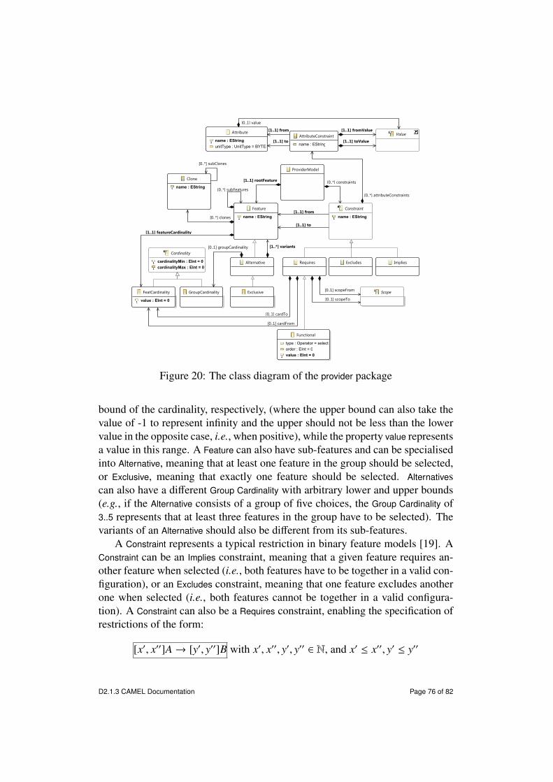
Alternative
Attribute
name : EStringunitType : UnitType = BYTES
Cardinality
cardinalityMin : EInt = 0cardinalityMax : EInt = 0
Constraint
name : EString
ExclusiveFeatCardinality
value : EInt = 0
Feature
name : EString
GroupCardinality
ProviderModel
Excludes ImpliesRequires
Functional
type : Operator = selectorder : EInt = 0value : EInt = 0
Scope
AttributeConstraint
name : EString
Value
Clone
name : EString [0..*] subFeatures
[1..1] featureCardinality
[0..1] groupCardinality [1..*] variants
[1..1] from
[1..1] to
[0..*] constraints[1..1] rootFeature
[0..1] cardFrom
[0..1] cardTo
[0..1] scopeFrom
[0..1] scopeTo
[0..*] attributeConstraints
[1..1] from
[1..1] to
[0..1] value
[1..1] fromValue
[1..1] toValue
[0..*] clones
[0..*] subClones
Figure 20: The class diagram of the provider package
bound of the cardinality, respectively, (where the upper bound can also take thevalue of -1 to represent infinity and the upper should not be less than the lowervalue in the opposite case, i.e., when positive), while the property value representsa value in this range. A Feature can also have sub-features and can be specialisedinto Alternative, meaning that at least one feature in the group should be selected,or Exclusive, meaning that exactly one feature should be selected. Alternativescan also have a di↵erent Group Cardinality with arbitrary lower and upper bounds(e.g., if the Alternative consists of a group of five choices, the Group Cardinality of3..5 represents that at least three features in the group have to be selected). Thevariants of an Alternative should also be di↵erent from its sub-features.
A Constraint represents a typical restriction in binary feature models [19]. AConstraint can be an Implies constraint, meaning that a given feature requires an-other feature when selected (i.e., both features have to be together in a valid con-figuration), or an Excludes constraint, meaning that one feature excludes anotherone when selected (i.e., both features cannot be together in a valid configura-tion). A Constraint can also be a Requires constraint, enabling the specification ofrestrictions of the form:
[x0, x00]A! [y0, y00]B with x0, x00, y0, y00 2 N, and x0 x00, y0 y00
D2.1.3 CAMEL Documentation Page 76 of 82

This restriction represents that if cardinality of feature A is between x0 andx00, the cardinality of feature B must be in [y0, y00].
A Requires constraint can be specialised into a Functional constraint, enablingthe specification of restrictions of the form:
[x0, x00]A! +[y]B with x0, x00, y 2 N, and x0 x00
This constraint represents that a feature A with cardinality between [x0, x00]requires y more instances of feature B in a valid configuration. Obviously, yshould be positive in this case.
A Requires constraint can also be specialised into an Attribute Constraint, en-abling the specification of restrictions of the form:
(A).c = X ! (B).d = Y
This constraint represents that if the attribute c of A has value X, then the at-tribute d of B must have value Y. Note that: (a) the attributes should be di↵erent,and (b) the value provided for the attributes should be included in the attributes’value type.
A.6 SecurityFigure 21 shows the class diagram of the security package.
Certifiable
CompositeSecurityMetric
CompositeSecurityMetricInstance
RawSecurityMetric
RawSecurityMetricInstance
SecurityCapability
name : EString
SecurityControl
name : EStringspecification : EString
SecurityDomain
id : EStringname : EString
SecurityProperty
SecuritySLO
CompositeMetricRawMetric
CompositeMetricInstance RawMetricInstance
Property
name : EStringdescription : EStringtype : PropertyType = ABSTRACT
ServiceLevelObjective
[1..1] domain[1..*] securityControls
[1..1] domain[1..1] subDomain
[0..*] securityProperties
[0..*] rawSecurityMetrics [0..*] compositeSecurityMetrics
[0..*] subDomain
Figure 21: The class diagram of the security package
D2.1.3 CAMEL Documentation Page 77 of 82

A SecurityControl represents a technical or administrative countermeasure thatis aimed at addressing a security risk in a cloud-based application. The propertyspecification is used to specify textual specifications of security controls providedby the di↵erent service providers specified in the CAMEL model.
A security control refers to the Raw- and CompositeSecurityMetrics, which spe-cialise Raw- and CompositeMetrics (see Section A.3), respectively, and representthe raw and composite security metrics associated with the security control. Italso has two references to SecurityDomain, which represents the security domainassociated with the security control (e.g., “Identity & Access Management”) andallows the grouping of security controls, properties, and metrics.
A SecurityProperty specialises Property (see Section A.3) and represents an ab-stract security property that is not measurable. A Certifiable specialises secur-ity property and represents a certifiable security property that is measurable. Itrefers to a particular security metric.
A SecuritySLO specialises ServiceLevelObjective (see Section A.2) and repres-ents a security SLO.
A.7 ExecutionFigure 22 shows the class diagram of the execution package.
SLOAssessment
name : EStringassessment : EBoolean = falseassessmentTime : EDate
Measurement
name : EStringvalue : EDouble = 0.0rawData : EStringmeasurementTime : EDate
ExecutionModel
ActionRealisation
name : EStringstartTime : EDateendTime : EDatelowLevelActions : EString
RuleTrigger
name : EStringtrigerringTime : EDate
ExecutionContext
name : EStringstartTime : EDateendTime : EDatetotalCost : EDouble = 0.0
ApplicationMeasurement
InternalComponentMeasurement
CommunicationMeasurement
VMMeasurement
[1..1] measurement
[0..*] measurements[0..*] sloAssessessments
[0..*] actionRealisations
[0..*] ruleTriggers
[1..*] actionRealisations
[1..1] executionContext
[1..1] executionContext
[0..*] executionContexts
[1..1] executionContext
Figure 22: The class diagram of the execution package
An ExecutionContext represents the execution context for a particular deploy-ment model. The properties startTime and endTime represent the date when theapplication execution started and ended, respectively. The property totalCost rep-
D2.1.3 CAMEL Documentation Page 78 of 82
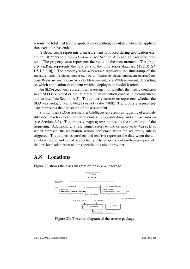
resents the total cost for the application execution, calculated when the applica-tion execution has ended.
A Measurement represents a measurement produced during application exe-cution. It refers to a MetricInstance (see Section A.3) and an execution con-text. The property value represents the value of the measurement. The prop-erty rawData represents the raw data in the time series database (TSDB) (cf.D5.1.2 [10]). The property measurementTime represents the timestamp of themeasurement. A Measurement can be an ApplicationMeasurement, an InternalCom-ponentMeasurement, a CommunicationMeasurement, or a VMMeasurement, dependingon which application or element within a deployment model it refers to.
An SLOAssessment represents an assessment of whether the metric conditionin an SLO is violated or not. It refers to an execution context, a measurement,and an SLO (see Section A.2). The property assessment represents whether theSLO was violated (value FALSE) or not (value TRUE). The property assessment-Time represents the timestamp of the assessment.
Similar to an SLO assessment, a RuleTrigger represents a triggering of a scalab-ility rule. It refers to an execution context, a ScalabilityRule, and an EventInstance(see Section A.3). The property triggeringTime represents the timestamp of thetriggering. Additionally, a rule trigger refers to one or more ActionRealisations,which represent the adaptation actions performed when the scalability rule istriggered. The properties startTime and endTime represent the date when the ad-aptation started and ended, respectively. The property lowLevelActions representsthe low level adaptation actions specific to a cloud provider.
A.8 LocationsFigure 23 shows the class diagram of the location package.
CloudLocation
/level : EInt = 0isAssignable : EBoolean = false
Country
GeographicalRegion
name : EStringalternativeNames : EString
Location
id : EString
LocationModel
[0..*] subLocations
[0..1] parent
[0..1] geographicalRegion
[0..*] parentRegions
[0..*] cloudLocations
[0..*] countries
[0..*] regions
Figure 23: The class diagram of the location package
D2.1.3 CAMEL Documentation Page 79 of 82

A Location represents a physical or virtual location. It can be specialised intoa GeographicalRegion, which represents a geographical region, or a CloudLocation,which represents a virtual location in a cloud (e.g., Amazon EC2 eu-west-1).The property name of GeographicalRegion represents the name in English, whilethe property alternativeNames represents possible alternative names in other nat-ural languages. A geographical region can refer to a parent region, which al-lows for the creation of hierarchies of geographical regions (e.g., continent, sub-continent, and country). A GeographicalRegion can be a Country, which representsa distinct entity in political geography. Similar to the geographical region, acloud location can refer to a parent location. Note that both the geographicalregion and the cloud location should not (recursively) refer to themselves.
A.9 UnitsFigure 24 shows the class diagram of the unit package.
CoreUnit
Dimensionless MonetaryUnit
RequestUnit
StorageUnit
ThroughputUnit TimeIntervalUnit
TransactionUnit
Unit
/dimensionType : UnitDimensionType = TIME_INTERVALname : EStringunit : UnitType = BYTES
UnitModel
[0..*] units
Figure 24: The class diagram of the unit package
A Unit represents an abstract unit. It can be specialised into the followingconcepts:
• CoreUnit, which represents the unit of CPU cores
• MonetaryUnit, which represents a monetary unit (e.g., EUROS)
• RequestUnit, which represents the unit of number requests
• StorageUnit, which represents the unit of storage (e.g., BYTES)
• ThroughputUnit, which represents the unit of throughput (e.g., REQUESTS-_PER_SECOND)
D2.1.3 CAMEL Documentation Page 80 of 82

• TimeIntervalUnit, which represents the unit of time interval (e.g., SECONDS)
• TransactionUnit, which represents the number of transactions
• Dimensionless, which represents a unit without dimension (e.g., a unit ofPERCENTAGE is dimensionless)
The property unit refers to UnitType, which is an enumeration of all possibleunit types. The property dimensionType refers to UnitDimensionType, which is anenumeration of all possible unit dimension types.
Figure 25 shows the class diagram of the enumerations in the unit package.
UnitDimensionType
TIME_INTERVALSTORAGECOSTTHROUGHPUTREQUEST_NUMTRANSACTION_NUMDIMENSIONLESSCORE_NUM
UnitType
BYTESKILOBYTESGIGABYTESMEGABYTESEUROSDOLLARSPOUNDSMILLISECONDSSECONDSMINUTESHOURSDAYSWEEKSMONTHSREQUESTSREQUESTS_PER_SECONDTRANSACTIONSTRANSACTIONS_PER_SECONDBYTES_PER_SECONDPERCENTAGECORES
Figure 25: The class diagram of the enumerations in the unit package
A.10 TypesFigure 26 shows the class diagram of the type package.
A Value represents a generic value. It can be specialised into a NumericValue,StringValue, BooleanValue, and EnumerateValue. A numeric value can be furtherspecialised into the IntValue, DoubleValue, and FloatValue. The property value istyped by the corresponding Java type of Ecore. A numeric value can also bespecialised into NegativeInf and PositiveInf, which represent negative and positiveinfinity, respectively, and can be used for specifying one of the two bounds ofrange-based value types. The StringValue and BooleanValue classes represent stringand boolean values, respectively. The property value is typed by the correspond-ing Java type of Ecore. The EnumerateValue represents an enumerated value. Theproperty name represents the string associated with the enumerated value, whilethe property value represents the integer associated with the value (or positionin the enumeration).
D2.1.3 CAMEL Documentation Page 81 of 82
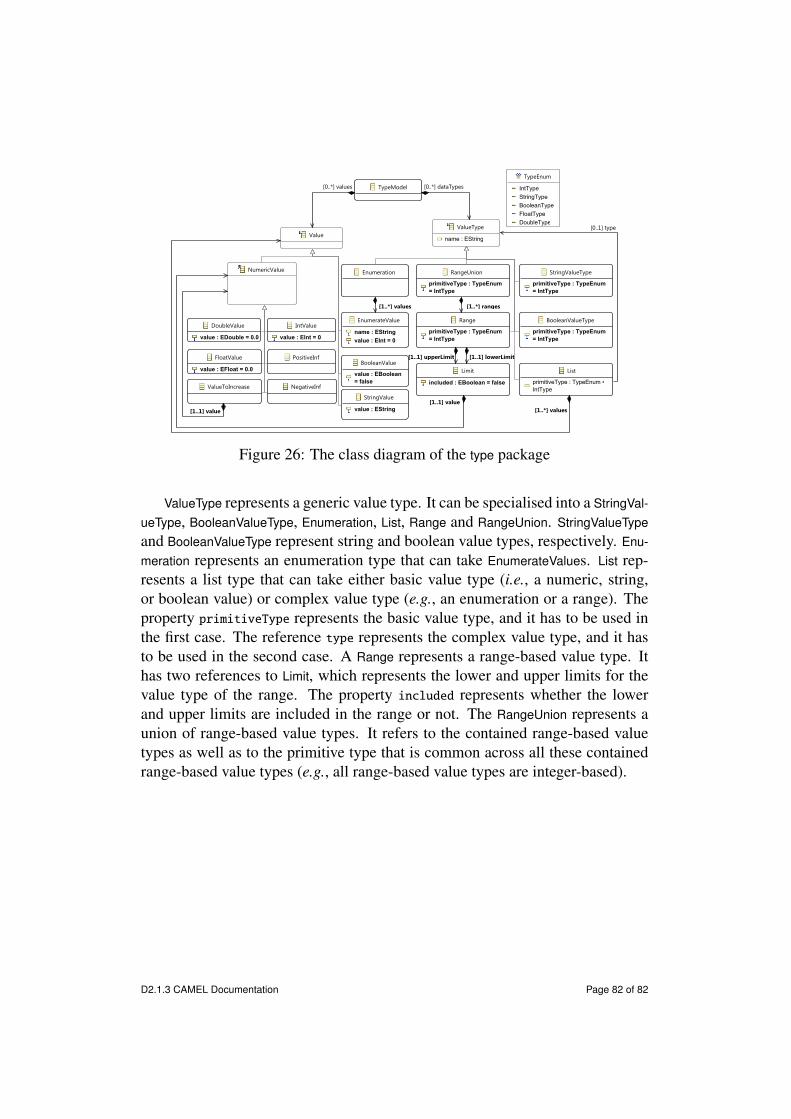
BooleanValue
value : EBoolean = false
BooleanValueType
primitiveType : TypeEnum = IntType
DoubleValue
value : EDouble = 0.0
EnumerateValue
name : EStringvalue : EInt = 0
Enumeration
FloatValue
value : EFloat = 0.0
IntValue
value : EInt = 0
Limit
included : EBoolean = false
List
primitiveType : TypeEnum = IntTypeNegativeInf
NumericValue
PositiveInf
Range
primitiveType : TypeEnum = IntType
RangeUnion
primitiveType : TypeEnum = IntType
StringValue
value : EString
StringValueType
primitiveType : TypeEnum = IntType
TypeEnum
IntTypeStringTypeBooleanTypeFloatTypeDoubleType
TypeModel
Value
ValueToIncrease
ValueType
name : EString
[1..*] values
[1..1] value[1..*] values
[0..1] type
[1..1] lowerLimit[1..1] upperLimit
[1..*] ranges
[0..*] dataTypes[0..*] values
[1..1] value
Figure 26: The class diagram of the type package
ValueType represents a generic value type. It can be specialised into a StringVal-ueType, BooleanValueType, Enumeration, List, Range and RangeUnion. StringValueTypeand BooleanValueType represent string and boolean value types, respectively. Enu-meration represents an enumeration type that can take EnumerateValues. List rep-resents a list type that can take either basic value type (i.e., a numeric, string,or boolean value) or complex value type (e.g., an enumeration or a range). Theproperty primitiveType represents the basic value type, and it has to be used inthe first case. The reference type represents the complex value type, and it hasto be used in the second case. A Range represents a range-based value type. Ithas two references to Limit, which represents the lower and upper limits for thevalue type of the range. The property included represents whether the lowerand upper limits are included in the range or not. The RangeUnion represents aunion of range-based value types. It refers to the contained range-based valuetypes as well as to the primitive type that is common across all these containedrange-based value types (e.g., all range-based value types are integer-based).
D2.1.3 CAMEL Documentation Page 82 of 82