model based bruce lewis us army rdec, sei affiliate ...€¢concurrency & redundancy management...
TRANSCRIPT

Aerospace Vehicle Systems Institute / Software Engineering Institute | Carnegie Mellon
Model Based Engineering to System
Architecture Virtual Integration (SAVI) with
Bruce Lewis
US Army RDEC, SEI Affiliate
Peter H Feiler
Software Engineering Institute
Dave RedmanIntegration (SAVI) with Demonstration
FAA Software & Airborne Electronic Hardware Conf.San Jose, CA
August 2009
Aerospace Vehicle Systems Institute
© Texas Engineering Experiment Station

Definitions
• Architecture Analysis & Design Language is a precise Architecture Description Language designed for Model-Based Engineering via virtual integration of the Embedded Software System.
• Model-Based Engineering of the Embedded Software System Architecture is the modeling and quantitative analysis of the integrated components, hardware and software, static and dynamic.software, static and dynamic.
• System Architecture Virtual Integration (SAVI) is a project and an industrial process and infrastructure enabling virtual integration and analyses of the system and embedded software system from acquisition through development –“integrate then build”.
FAA SW & AEH Conference | San Jose, CA
SAVI is being developed for next gen aircraft and
upgrades to current aircraft but applicable to any ESS.
© Texas Engineering Experiment Station 2

We Rely on Embedded Systems for Safe Vehicle Operation
© Texas Engineering Experiment Station 3FAA SW & AEH Conference | San Jose, CA
Embedded software systems
introduce a new class of problems
not addressed by traditional system
modeling & analysis

Mismatched Assumptions Cause Many Issues
System Engineer Control Engineer
Ap
plica
tion
De
velo
pe
rH
ard
wa
re E
ng
ine
er
System
Under
Control
Control
System
Physical Plant
Characteristics
Lag, proximity
Data Stream
Characteristics
End-to-end latency
Precision Units
Ariane 4/5
SysML does not address Embedded Software
System Architecture Issues
Ap
plica
tion
De
velo
pe
rH
ard
wa
re E
ng
ine
er
Compute
Platform
Runtime
Architecture
Application
Software
Embedded SW System Engineer
End-to-end latency
(F16)
Concurrency
Communication
ITunes crashes on
dual-cores
Distribution & Redundancy
Virtualization of HW
(ARPA-Net split)
Why do system level failures still occur despite fault tolerance techniques being deployed in systems?
© Texas Engineering Experiment Station 4FAA SW & AEH Conference | San Jose, CA

Architecture Level Software System Faults& Their Root Causes
Violation of data stream assumptions
•Stream miss rates, Mismatched data representation, Latency jitter & age
Partitions as Isolation Regions
•Space, time, and bandwidth partitioning
•Isolation not guaranteed due to undocumented resource sharing
•fault containment, security levels, safety levels, distribution
Virtualization of time & resources
End-to-end latency analysis
Port connection consistency
Partitioned architecture models
Model compliance
•Logical vs. physical redundancy
•Time stamping of data & asynchronous systems
Inconsistent System States & Interactions
•Modal systems with modal components
•Concurrency & redundancy management
•Application level interaction protocols
Performance impedance mismatches
•Processor, memory & network resources
•Compositional & replacement performance mismatches
•Unmanaged computer system resources
Fault propagation
Security analysis
Architectural redundancy
patterns
Resource budget analysis &
task roll-up analysis
Resource allocation &
deployment configurations
Virtual processors & buses
Synchronization domains
© Texas Engineering Experiment Station 5FAA SW & AEH Conference | San Jose, CA

Cost & Time Reduction due to Early Fault Discovery
System
Design
System
Test
Acceptance
Test
Requirements
Engineering
30x20.5%
1x
10%, 50.5%
0%, 9% 15x
70%, 3.5%
10x
System & embedded
software system faults
© Texas Engineering Experiment Station 6FAA SW & AEH Conference | San Jose, CA
5x
Software
Architectural
Design
Component
Software
Design
Code
Development
Unit
Test
Integration
Test
Source: NIST Planning report 02-3, “The
Economic Impacts of Inadequate
Infrastructure for Software Testing”, May
2002.
Where faults are introduced
Where faults are found
The estimated nominal cost for fault removal
1x
20%, 16%
10x
SAVI
applies
MBE early
From
Acquisition
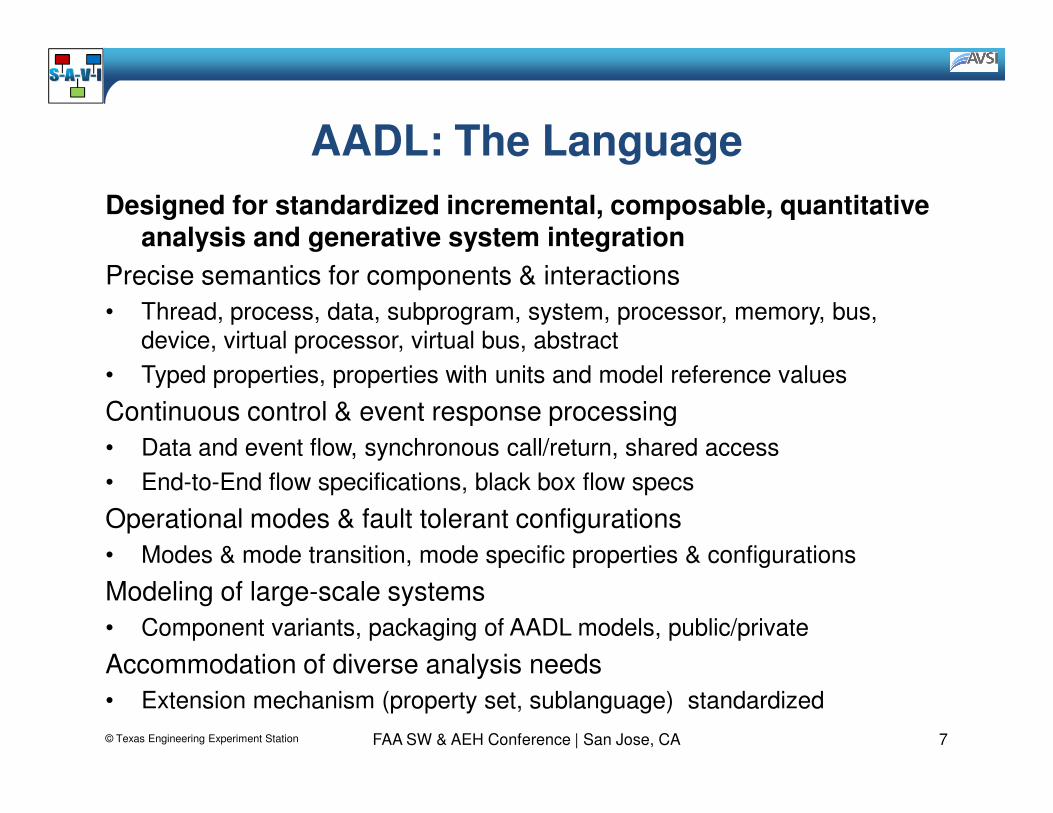
AADL: The Language
Designed for standardized incremental, composable, quantitative analysis and generative system integration
Precise semantics for components & interactions
• Thread, process, data, subprogram, system, processor, memory, bus,
device, virtual processor, virtual bus, abstract
• Typed properties, properties with units and model reference values
Continuous control & event response processingContinuous control & event response processing
• Data and event flow, synchronous call/return, shared access
• End-to-End flow specifications, black box flow specs
Operational modes & fault tolerant configurations
• Modes & mode transition, mode specific properties & configurations
Modeling of large-scale systems
• Component variants, packaging of AADL models, public/private
Accommodation of diverse analysis needs
• Extension mechanism (property set, sublanguage) standardized
© Texas Engineering Experiment Station 7FAA SW & AEH Conference | San Jose, CA

Modeling an Embedded System Architecture
Elements of an embedded system architecture
Application SW Architecture (task
& communication)
Computer platform
architecture (processors &
networks)
Physical system/environment (interface with
embedded SW/HW)
© Texas Engineering Experiment Station 8FAA SW & AEH Conference | San Jose, CA
Logical interface between software
and physical system
Physical interface between computer
platform and physical system
Deployment of software on computer platform
SAVI provides an industrial and
acquisition process as well as the infrastructure for application of MBE
SAE AADL supports modeling,
analysis, and auto-generation of embedded system architectures.
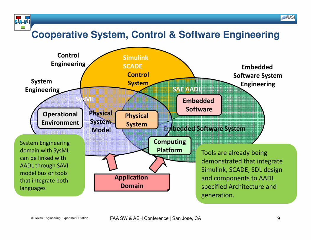
Cooperative System, Control & Software Engineering
Control
SystemSAE AADL
Embedded
Software System
EngineeringSystem
Engineering
Physical
System
SysML
Physical
System
Embedded
SoftwareOperational
Environment
Simulink
SCADE
Control
Engineering
© Texas Engineering Experiment Station 9FAA SW & AEH Conference | San Jose, CA
Embedded Software SystemSystem
ModelSystem
Computing
Platform
Application
Domain
Environment
System Engineering
domain with SysML
can be linked with
AADL through SAVI
model bus or tools
that integrate both
languages
Tools are already being
demonstrated that integrate
Simulink, SCADE, SDL design
and components to AADL
specified Architecture and
generation.

Potential Model-based Engineering Pitfalls
Potential Solution
Inconsistency between independently developed
analytical models
Architecture-centric model repository
The Issues
System models
System implementation
Confidence that model reflects implementation
Generation from validated models
© Texas Engineering Experiment Station 10FAA SW & AEH Conference | San Jose, CA

Architecture-Centric Engineering Approach
SecurityIntrusion
Integrity
Confidentiality
Availability & ReliabilityMTBF
FMEA
Hazard analysis
SAE AADLArchitecture Model
Virtual Integration & Validation of
System Architecture
Real-timePerformanceExecution time/
Deadline
Deadlock/starvation
Latency
ResourceConsumptionBandwidth
CPU time
Power consumption
Data precision/
accuracy
Temporal
correctness
Confidence
Data Quality
Auto-generated
analytical models
© Texas Engineering Experiment Station 11FAA SW & AEH Conference | San Jose, CA
SAVI Model
Repository
based on
same
concept, +
Acquisition
incremental
refinement,
Proprietary
data,
Distribution
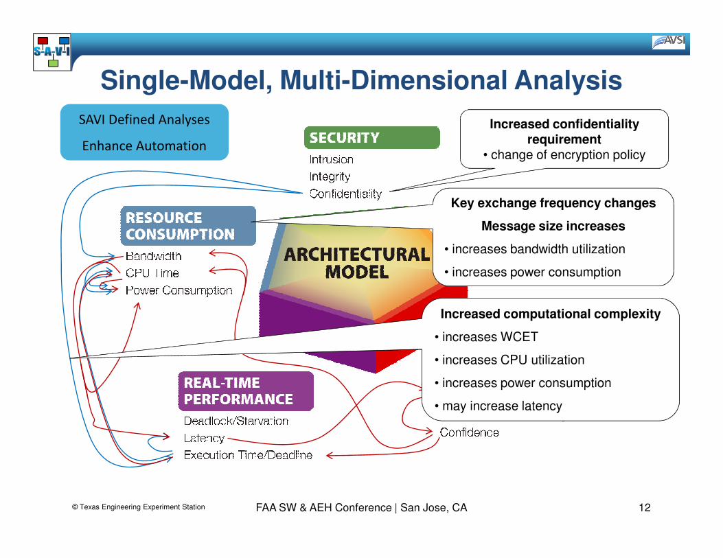
Single-Model, Multi-Dimensional Analysis
Increased confidentiality requirement
• change of encryption policy
Key exchange frequency changes
Message size increases
• increases bandwidth utilization
• increases power consumption
SAVI Defined Analyses
Enhance Automation
© Texas Engineering Experiment Station 12FAA SW & AEH Conference | San Jose, CA
Increased computational complexity
• increases WCET
• increases CPU utilization
• increases power consumption
• may increase latency

Key Benefits of AADL Standard
Consistent, rich, compiled model semantics for
architecture modeling, analysis and generation of
embedded systems.
Supporting incremental specification, multi-dimensional &
multi-fidelity modeling & analysis based on a single-source
Providing a semantically consistent interchange
format, AADL XMI, for integration of models
across supplier repositories & interfacing to
analysis & generation tools.
multi-fidelity modeling & analysis based on a single-source
architecture model.
© Texas Engineering Experiment Station 13FAA SW & AEH Conference | San Jose, CA

Software
System
Design
System
Test
Acceptance
Test
Top-Level
Verification Items
High-level
AADL Model
Detailed
Sensitivity analysis for uncertainty
Requirements
Engineering
Confidence in implementation
From Prediction to Validation
Virtual Integration Throughout Life Cycle
Software
Architectural
Design
Component
Software
Design
Code
Development
Unit
Test
Integration
Test
Detailed
AADL Model
Specify Model-
Code Interfaces
→ generation of test cases← updating models with actual data
SAVI defines Analyses
Fidelity and Timing
© Texas Engineering Experiment Station 14FAA SW & AEH Conference | San Jose, CA

Benefits of Virtual Integration• Reduce the risks
– Analyze system early and throughout life cycle
– Understand system wide impact
– Validate assumptions across system
• Increase the confidence
– Validate models to complement integration testing– Validate models to complement integration testing
– Validate model assumptions in operational system
– Evolve system models in increasing fidelity
• Reduce the cost
– Fewer system integration problems
– Fewer validation steps through use of validated generators
© Texas Engineering Experiment Station 15FAA SW & AEH Conference | San Jose, CA

The Aerospace Vechicle Systems Institute
AVSI is a global cooperative of aerospace companies, government organizations, and academic institutions
The System Architecture Virtual
FAA SW & AEH Conference | San Jose, CA
The System Architecture Virtual
Integration program is an AVSI
program addressing virtual
integration of systems.
SEI was selected as the contractor
to help work the Proof of Concept
Effort
Past AVSI projects have covered
the breadth of aerospace systems
and current research includes
projects in the areas of reliability,
certification, and virtual
integration.© Texas Engineering Experiment Station 16
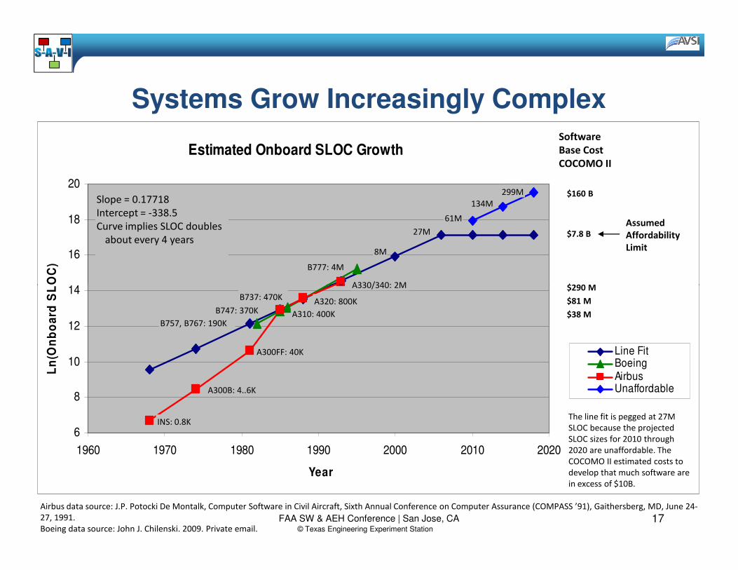
Systems Grow Increasingly Complex
Estimated Onboard SLOC Growth
14
16
18
20
Ln
(On
bo
ard
SL
OC
)
299M
27M
A330/340: 2M
8M
Slope = 0.17718
Intercept = -338.5
Curve implies SLOC doubles
about every 4 years
134M
61M
B777: 4M
$160 B
$7.8 B
$290 M
Software
Base Cost
COCOMO II
Assumed
Affordability
Limit
Airbus data source: J.P. Potocki De Montalk, Computer Software in Civil Aircraft, Sixth Annual Conference on Computer Assurance (COMPASS ’91), Gaithersberg, MD, June 24-
27, 1991.
Boeing data source: John J. Chilenski. 2009. Private email.
6
8
10
12
14
1960 1970 1980 1990 2000 2010 2020
Year
Ln
(On
bo
ard
SL
OC
)
Line FitBoeingAirbusUnaffordable
A330/340: 2M
A320: 800K
A310: 400K
A300FF: 40K
A300B: 4..6K
INS: 0.8K
B757, B767: 190K
B747: 370K
B737: 470K
The line fit is pegged at 27M
SLOC because the projected
SLOC sizes for 2010 through
2020 are unaffordable. The
COCOMO II estimated costs to
develop that much software are
in excess of $10B.
$290 M
$81 M
$38 M
© Texas Engineering Experiment Station
17FAA SW & AEH Conference | San Jose, CA

Leading to Schedule and Cost Overruns
Errors Discovered Late in the Development Cycle Contribute More Cost Growth
FAA SW & AEH Conference | San Jose, CA© Texas Engineering Experiment Station 18

New Development of Safe Aircraft is Reaching the Limits of Affordability
• Complexity will continue to increase and the situation will get worse, not better
• Individual companies cannot afford to solve this issue alonesolve this issue alone
• The industry cannot afford to solve it multiple times
• We can’t afford not to solve it
FAA SW & AEH Conference | San Jose, CA
A coordinated, industry-wide effort is needed
to solve this issue.© Texas Engineering Experiment Station 19
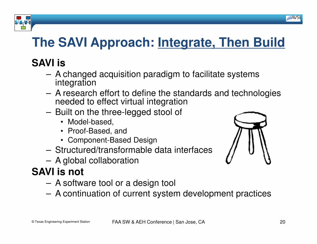
The SAVI Approach: Integrate, Then Build
SAVI is– A changed acquisition paradigm to facilitate systems
integration
– A research effort to define the standards and technologies needed to effect virtual integration
– Built on the three-legged stool of• Model-based,• Model-based,
• Proof-Based, and
• Component-Based Design
– Structured/transformable data interfaces
– A global collaboration
SAVI is not– A software tool or a design tool
– A continuation of current system development practices
FAA SW & AEH Conference | San Jose, CA© Texas Engineering Experiment Station 20

SAVI Aims to Enable Virtual Systems Integration to Discover Issues Earlier in Development
Standardized architecture
language with strong
semantics, the Model Bus
and Model Repository
concepts in SAVI enable…
… early validation of
system and
embedded software
system behavior to
reduce integration
errors.
concepts in SAVI enable…
© Texas Engineering Experiment Station 21FAA SW & AEH Conference | San Jose, CA

Modified Business ModelSystem Integrator defines a new product using internal repository of virtual “parts”
Specifications for virtual subystems sent to suppliers
Proposed and developed subsystem models incrementally provided to integrator
System Integrator Suppliers
Model Exchange Via
Standardized
Interchange Formats
© Texas Engineering Experiment Station 22FAA SW & AEH Conference | San Jose, CA
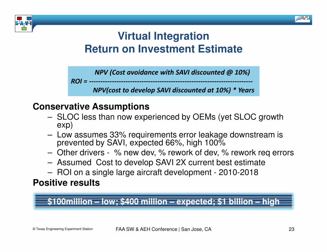
Virtual IntegrationReturn on Investment Estimate
Conservative Assumptions– SLOC less than now experienced by OEMs (yet SLOC growth
exp)
NPV (Cost avoidance with SAVI discounted @ 10%)
ROI = ------------------------------------------------------------------------
NPV(cost to develop SAVI discounted at 10%) * Years
exp)– Low assumes 33% requirements error leakage downstream is
prevented by SAVI, expected 66%, high 100%– Other drivers - % new dev, % rework of dev, % rework req errors– Assumed Cost to develop SAVI 2X current best estimate– ROI on a single large aircraft development - 2010-2018
Positive results
© Texas Engineering Experiment Station 23FAA SW & AEH Conference | San Jose, CA
$100million – low; $400 million – expected; $1 billion – high
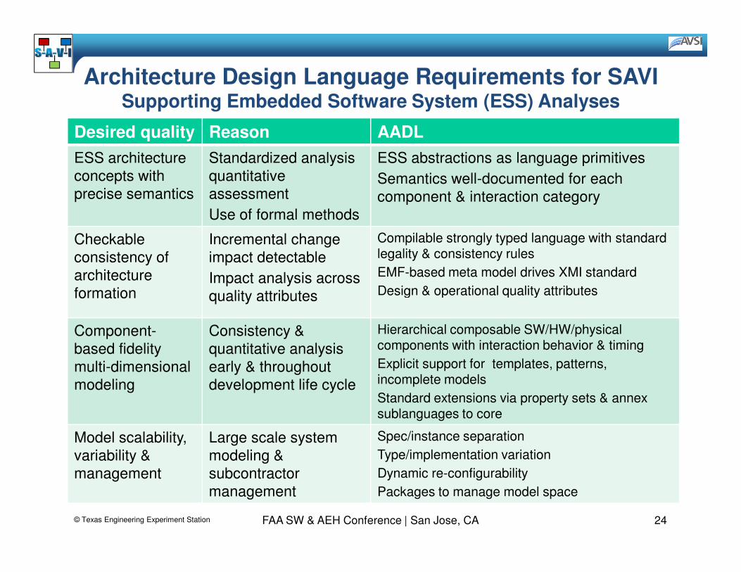
Architecture Design Language Requirements for SAVISupporting Embedded Software System (ESS) Analyses
Desired quality Reason AADL
ESS architecture
concepts with
precise semantics
Standardized analysis
quantitative
assessment
Use of formal methods
ESS abstractions as language primitives
Semantics well-documented for each
component & interaction category
Checkable
consistency of
architecture
formation
Incremental change
impact detectable
Impact analysis across
Compilable strongly typed language with standard legality & consistency rules
EMF-based meta model drives XMI standard
Design & operational quality attributesformation quality attributes Design & operational quality attributes
Component-
based fidelity
multi-dimensional
modeling
Consistency &
quantitative analysis
early & throughout
development life cycle
Hierarchical composable SW/HW/physical components with interaction behavior & timing
Explicit support for templates, patterns, incomplete models
Standard extensions via property sets & annex sublanguages to core
Model scalability,
variability &
management
Large scale system
modeling &
subcontractor
management
Spec/instance separation
Type/implementation variation
Dynamic re-configurability
Packages to manage model space
© Texas Engineering Experiment Station 24FAA SW & AEH Conference | San Jose, CA
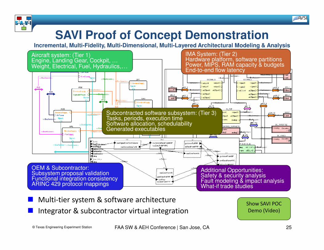
SAVI Proof of Concept DemonstrationIncremental, Multi-Fidelity, Multi-Dimensional, Multi-Layered Architectural Modeling & Analysis
Aircraft system: (Tier 1)Engine, Landing Gear, Cockpit, …Weight, Electrical, Fuel, Hydraulics,…
IMA System: (Tier 2)Hardware platform, software partitionsPower, MIPS, RAM capacity & budgetsEnd-to-end flow latency
Subcontracted software subsystem: (Tier 3)Tasks, periods, execution timeSoftware allocation, schedulability
FAA SW & AEH Conference | San Jose, CA
� Multi-tier system & software architecture
� Integrator & subcontractor virtual integration
Software allocation, schedulabilityGenerated executables
OEM & Subcontractor:Subsystem proposal validationFunctional integration consistencyARINC 429 protocol mappings
Additional Opportunities:Safety & security analysisFault modeling & impact analysisWhat-if trade studies
© Texas Engineering Experiment Station 25
Show SAVI POC
Demo (Video)
Contacts
Dr. Donald Ward – SAVI Program Manager
Bruce Lewis – AADL chair
© Texas Engineering Experiment Station 26FAA SW & AEH Conference | San Jose, CA
Dr. David Redman –Director, AVSI
Peter Feiler – AADL Technical Lead
SAVI next phase is being planned – its your opportunity to join – contact Dr. Ward for more information
Backup Slides
FAA SW & AEH Conference | San Jose, CA© Texas Engineering Experiment Station 27
Aerospace Vehicle Systems Institute / Software Engineering Institute | Carnegie Mellon
Model Based Engineering to System
Architecture Virtual Integration (SAVI) with Integration (SAVI) with
Demonstration
FAA Software & Airborne Electronic Hardware Conf.Bruce Lewis (US Army RDEC), Peter H Feiler (SEI), D. Redman (AVSI)
San Jose, CA August 2009
© Texas Engineering Experiment Station

Modeling an Embedded System Architecture
Elements of an embedded system architecture• Application SW Architecture (task & communication) PLUS
• Computer platform architecture (processors & networks) PLUS
• Physical system/environment (interface with embedded SW/HW) PLUS
• Logical interface between software and physical system • Logical interface between software and physical system PLUS
• Physical interface between computer platform and physical system PLUS
• Deployment of software on computer platform
© Texas Engineering Experiment Station 29FAA SW & AEH Conference | San Jose, CA
SAVI provides an industrial and acquisition process as well as the infrastructure for application of MBE
SAE AADL supports modeling, analysis, and auto-generation of embedded
system architectures.

The Systems and Supply Chain Are Heirarchical
OEM
FAA SW & AEH Conference | San Jose, CA
Tier 1 Supplier
Tier 2 Supplier
We should expect the same of the
tools and processes
employed in their development© Texas Engineering Experiment Station 30
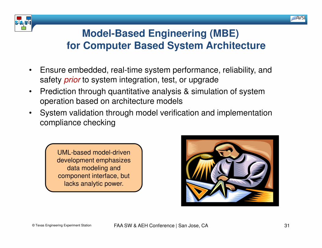
Model-Based Engineering (MBE) for Computer Based System Architecture
• Ensure embedded, real-time system performance, reliability, and safety prior to system integration, test, or upgrade
• Prediction through quantitative analysis & simulation of system operation based on architecture models
• System validation through model verification and implementation compliance checkingcompliance checking
UML-based model-driven
development emphasizes
data modeling and
component interface, but
lacks analytic power.
© Texas Engineering Experiment Station 31FAA SW & AEH Conference | San Jose, CA
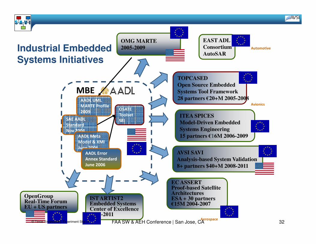
Industrial Embedded Systems Initiatives
SAE AADL
Standard
Automotive
OSATE
Toolset
SEI
Avionics
MBE
TOPCASED
Open Source Embedded
Systems Tool Framework
28 partners €20+M 2005-2008
ITEA SPICES
Model-Driven Embedded
OMG MARTE
2005-2009
EAST ADL
Consortium
AutoSAR
AADL UML
MARTE Profile
2009
Standard
Nov 2004
SEI
AADL Meta
Model & XMI
June 2006
AADL Error
Annex Standard
June 2006
Aerospace
Model-Driven Embedded
Systems Engineering
15 partners €16M 2006-2009
AVSI SAVI
Analysis-based System Validation
8+ partners $40+M 2008-2011
EC ASSERTProof-based SatelliteArchitectures ESA + 30 partners€15M 2004-2007
IST ARTIST2Embedded SystemsCenter of Excellence2007-2011
OpenGroupReal-Time ForumEU + US partners
© Texas Engineering Experiment Station 32FAA SW & AEH Conference | San Jose, CA
AADL & Other Standards
• AADL & OMG MARTE – Joint AADL UML profile effort– AADL subprofile appendix in MARTE Document (in
ballot 2009)
• Embedded systems & System engineering– Meeting of minds: technical leads of AADL & SysML
(Dec 2008)– Meeting of minds: technical leads of AADL & SysML
(Dec 2008)– Coordination: AADL, MARTE, SysML (April 2009)– Collaboration: AADL, MARTE, SysML, INCOSE
cross membership & joint meetings– STEP AP-233 Standards– DO-178 / DO-254– ARP 2754
© Texas Engineering Experiment Station 33FAA SW & AEH Conference | San Jose, CA

Proof of Concept EffortObjectives
• Develop a credible RoI estimate
• Define a roadmap for development of SAVI
• Develop a Proof of Concept Modeling environment:
– Establish a prototype Model Bus
– Establish a prototype Model Repository
– Define a sample model that captures targeted systems properties
– Perform system analyses across multiple levels of abstraction
FAA SW & AEH Conference | San Jose, CA© Texas Engineering Experiment Station 34
Accomplishments
First Feasibility Demonstration Completed• Investigation of Acquisition Model showed significant changes• Proof of Concept demonstration suggested SAVI is technically
feasible• Laid out Road Map to evolve new paradigm• Estimated Return on Investment (RoI) from software requirements
alone is very favorable
Acquisition Model Changes Significantly• “Integrate, then Build”
– Static view – complete information model from requirements phase onward
– Formal definition of proof-based models and data structure
– Dynamic view – explicit linkage of models across tiers
• Demonstrated concept of tool neutrality through the Model Bus
FAA SW & AEH Conference | San Jose, CA© Texas Engineering Experiment Station 35
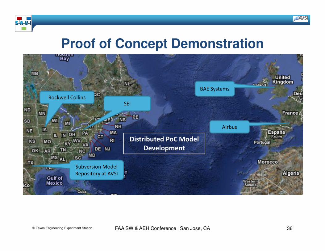
Proof of Concept Demonstration
Airbus
BAE Systems
Rockwell CollinsSEI
FAA SW & AEH Conference | San Jose, CA
Subversion Model
Repository at AVSI
Airbus
Distributed PoC Model
Development
© Texas Engineering Experiment Station 36

Proof of Concept Demonstration (2)
• Three Models (Tiers 1, 2, and 3) Analyzed– Tier 1 (Aircraft level)
– Tier 2 (Aircraft system level)
– Tier 3 (Sub-system/LRU level)
• Analysis and Demonstration– Propagate requirements and constraints– Propagate requirements and constraints
– Higher level model down to suppliers' lower level models
– Verification of lower level models satisfies higher level requirements and constraints
• Evaluation Based on Quality Factors– Started with 19 (Criticality, Frequency, Difficulty, Cost,
Breadth...)
– Video demonstrations available
FAA SW & AEH Conference | San Jose, CA© Texas Engineering Experiment Station 37
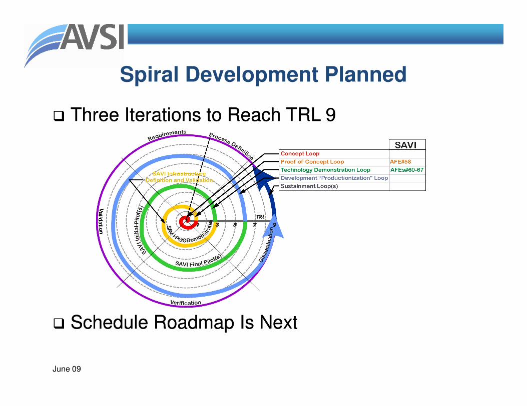
Spiral Development Planned
�� Three Iterations to Reach TRL 9Three Iterations to Reach TRL 9
June 09
�� Schedule Roadmap Is NextSchedule Roadmap Is Next

SAVI Development Roadmap2010 2011 2012 2013 2014 2015 2016
SAVI DEPLOYMENT
2009
SAVI Tools pre-implementation
Encapsulation
SAVI PROJECT
Models
Functional at model level
SAVI Processdescription v1.0
Model Bus &Model Repository
Specs
ADL Selected
ADL based & Multi-level
SAVI Processdescription v1.1
Model Bus &Model Repository
Specs v2.0
Full SAVI systems scope
FunctionalInterfaces Functional & types Aircraft signals
Requirements Func. at ADL component
SAVI Tools & Process
AFE 59?AFE 59?AFE 59?AFE 59?AFE 58AFE 58AFE 58AFE 58
FAA SW & AEH Conference | San Jose, CA
Full supply chain integration
COMMUNICATION
Partial Supply Chain integration (SAVI partners)
Tools Vendors Integration
Interfaces & existing modelsArchitectural model
Analysis tools Safety, functions, weight
Functional at model level
Simulation tools Simulation app. gen. Full simulation capabilities
SAVI v1.0 SAVI v2.0
Performances analyses
Full data
SAVI v3.0
Full analyses
Requirements Func. at ADL component
Configuration mgt. Version mgt Full services
Basic productionDocumentation prod. Full internal prod. Full external prod.
ADL visualizationRepository MMI Analysis & Simul. Integ.
ADL & models exchangesI/O services IP / security / IS integ.
Tools Vendors (partners)
AIRCRAFT APPLICATIONS
Architecture design Prelim. system design Aircraft programSAVI partners All suppliers
Airframer
Suppliers
© Texas Engineering Experiment Station 39

Predictability through Virtual Integration• Reduce the risks
– Analyze system early and throughout life cycle
– Understand system wide impact
– Validate assumptions across system
• Increase the confidence– Validate models to complement integration testing– Validate models to complement integration testing
– Validate model assumptions in operational system
– Evolve system models in increasing fidelity
• Reduce the cost– Fewer system integration problems
– Fewer validation steps through use of validated generators
© Texas Engineering Experiment Station 40FAA SW & AEH Conference | San Jose, CA

Questions?
David Redman, Ph.D.
Director
Aerospace Vehicle Systems Institute
Dr. Don Ward
p: 254-842-5021
f: 979-845-1696
FAA SW & AEH Conference | San Jose, CA
Aerospace Vehicle Systems Institute
746C HR Bright Bldg 3141 TAMU
College Station, TX 77843-3141
p: 979-862-2316
f: 979-845-1696
m: 979-218-2272
f: 979-845-1696
m: 979-218-2272
© Texas Engineering Experiment Station 41