model 9100 modular frequency/time system - … model 9100 modular frequency/time system tm4400013...
TRANSCRIPT

TRAK MODEL 9100 MODULAR FREQUENCY/TIME SYSTEM
TM4400013 Rev D
TECHNICAL MANUAL
(TM4400013)
MODEL 9100
Modular Frequency/Time System
Revision D
October 2006
TRAK Microwave Corporation 4726 Eisenhower Boulevard Tampa, Florida 33634 USA
Telephone (813) 901-7200 Fax (813) 901-7491 www.trak.com

TRAK MODEL 9100 MODULAR FREQUENCY/TIME SYSTEM
TM4400013 Rev, D i
REV DESCRIPTION DATE APPROVED
D Initially Released at Revision D 061031
STATIC AWARENESS
The 9100-8 Modular System contains CMOS IC’s that can be damaged by electrostatic discharge during handling. The following practices minimize the likelihood of CMOS IC damage: 1. Use a static-free work station. 2. Avoid PLASTIC, VINYL, and STYROFOAM in work area. 3. Discharge personal static before handling. Use a grounded antistatic wrist strap. 4. Minimize handling. Do NOT remove and replace IC’s by hand. 5. Use grounded IC removal and insertion tools 6. If required, handle the IC’s only by the body - NOT by the leads. Use grounded wrist strap. 7. Do not slide the IC over any surface.

TRAK MODEL 9100 MODULAR FREQUENCY/TIME SYSTEM
TM4400013 Rev, D ii
Frequency & Time Systems Model 9100

TRAK MODEL 9100 MODULAR FREQUENCY/TIME SYSTEM
TM4400013 Rev, D iii
TABLE OF CONTENTS
CHAPTER 1 INTRODUCTION
Paragraph Page 1-1 General 1-1 1-2 Level of Coverage 1-1 1-3 Organization of the Manual 1-1 1-4 Functional Description 1-2 1-5 Physical Description 1-4 1-6 Environmental Characteristics 1-4 1-7 Power Requirements 1-4 1-8 EMC/EMI 1-4 1-9 Input and Output Characteristics 1-5 1-10 Oscillator Options 1-8 1-11 Minor & Major Alarms 1-8
CHAPTER 2 INSTALLATION
2-1 Unpacking Procedure 2-1 2-2 System Mounting Procedure 2-1 2-3 Antenna Mounting 2-1 2-4 Input and Output Signal Connections 2-1 2-5 Input Power 2-2 2-6 Rear Panel Connectors and Fuses 2-2 2-7 Multi-pin Interface Connectors 2-3 2-8 Module Setup 2-5
CHAPTER 3 OPERATION
3-1 General 3-1 3-2 Front-Panel Controls and Indicators 3-1 3-3 Initial Synchronization 3-8 3-4 TOD Output 3-9 3-5 Remote Operation 3-10
CHAPTER 4 MAINTENANCE
4-1 General 4-1 4-2 Maintenance Philosophy 4-1 4-3 Preventive Maintenance 4-1 4-4 Replacement Modules 4-1 4-5 Trouble Shooting Guide 4-1

TRAK MODEL 9100 MODULAR FREQUENCY/TIME SYSTEM
TM4400013 Rev, D iv
CHAPTER 5 REPLACEMENT PARTS LIST
5-1 General 5-1
LIST OF ILLUSTRATIONS
Figure Page
Model 9100 Modular Frequency/Time System iii 1-1 Model 9100 Panel Views 1-2 1-2 Model 9100 Functional Block Diagram 1-3 2-1 Model 9100 Rear Panel 2-2 2-2 Model 9106 Digital Distribution (DDM) Switch Locations 2-5 2-3 Model 9107 Frequency Distribution Module (FDM) Jumper Locations 2-6 2-4 Model 9111 Telecommunications Generator (TEL) Switch and Jumper Locations 2-7 3-1 Model 9100 Front Panel 3-1 3-2 Model 9101 GPS Reference Front Panel 3-2 3-3 Model 9106 Digital Distribution DDM Front Panel 3-3 3-4 Model 9111 Telecom Signal Generator Front Panel 3-4 3-5 Model 9107 Frequency Distribution FDM Front Panel 3-5 3-6 Model 9104 Fault Sensing and Switching Unit (FSU) Front Panel 3-6 3-7 Model 9120-2 Power Supply Front Panel 3-7
LIST OF TABLES
Table Page 1-1 Interface Cables for EMC Compliance 1-4
1-2 Output Characteristics, References 1-5 1-3 Output Characteristics, RS-232 and TOD 1-7 1-4 Output Characteristics, Alarms 1-7 1-5 I/O Characteristics, 10BaseT, NTS 1-7 1-6 Input Characteristics, GPS Antenna 1-7 1-7 Oscillator Characteristics 1-8 1-8 Major and Minor Alarm Conditions 1-10 2-1 Rear Panel Connectors, Fuse, and Switch 2-2 2-2 10Base T Connections 2-3 2-3 Alarms 2-3 2-4 TOD Outputs 2-4 2-5 RS-232 Outputs 2-4 2-6 Reference Outputs 2-4 2-7 DDM Output Signal Switch Positions 2-5 2-8 FDM Input Signal Jumper Positions, T1 2-6 2-9 TEL Framing Format Switch Positions, T1 2-8 2-10 TEL Line Length Compensation Switch Positions, T1 2-8 2-11 TEL Framing Format Switch Positions, E1 2-8 2-12 TEL RS-422 Clock J1 Connections 2-9 2-13 TEL Framed J2 Connections 2-9 3-1 Request Command List 3-12 3-2 Setup Commands List 3-12 5-1 Replacement Modules 5-1

TRAK MODEL 9100 MODULAR FREQUENCY/TIME SYSTEM
TM4400013 Rev, D v
APPENDICES
Appendix A Model 9100 Data Sheet Appendix B NTS Option Appendix C Commonly Used Time Code Formats Appendix D Model 9100 DC Power Input Options Appendix E GPS Antenna Installation and Cable Options Appendix F Model 9200
G & up Module Descriptions

TRAK MODEL 9100 MODULAR FREQUENCY/TIME SYSTEM
TM4400013 Rev. D 1-1
CHAPTER 1
INTRODUCTION 1-1 GENERAL This manual contains the description, installation, operation, and maintenance instructions for the Model 9100 Modular Frequency/Time System (MFTS). It is intended to provide electronics personnel with the information necessary to operate the instrument and to maintain it to the lowest replaceable unit, LRU, or assembly level. 1-2 LEVEL OF COVERAGE This manual provides coverage to the LRU only. No schematic or logic diagrams of replaceable assemblies are provided. Unlike instruments in use a few decades ago, where it was possible to troubleshoot to the logic gate level, the Model 9100 uses modern technology consisting of CPU’s, gate arrays, and imbedded software. Packaging is largely surface-mount technology. Only factory-trained technicians with a high level of training can perform maintenance below the LRU level. Most LRU’s have an MTBF in excess of ten years, so frequent replacements are usually not required. 1-3 ORGANIZATION OF THIS MANUAL The body of this manual describes operation of the basic Model 9100 and its most common synchronization options (plug-in modules). All other plug-in option modules (code generators, signal generators, drivers, I/O, special oscillators, and special power inputs) are described in appendices. The appendix arrangement is as follows: Appendix A Model 9100 Data Sheet Appendix B Network Time Server Appendix C Commonly Used Time Code Formats Appendix D Optional Power Input and Output Signals Appendix E GPS Antenna Installation and Options Appendix F Model 9200 Manual Appendix G Module Descriptions Appendix H CE Compliance Certification

TRAK MODEL 9100 MODULAR FREQUENCY/TIME SYSTEM
TM4400013 Rev. D 1-2
Figure 1-1 Typical Model 9100 Modular Frequency/Time System Front Panel
Figure 1-1 Typical Model 9100 Modular Frequency/Time System Rear Panel
1.4 FUNCTIONAL DESCRIPTION The Model 9100 MFTS is a system providing ultra-stable frequency, time, and reference signals, referenced to the GPS satellite system. By selecting the appropriate functional modules, the system is easily configured for a variety of frequency and timing applications. Features include the following: • Single or dual redundant operation • GPS Disciplined single, double oven crystal oscillator, and/or rubidium oscillators. • Standard references include 10 MHz, 5 MPPS, 1 PPS, Composite and IRIG B time code. Optional
references include T1 or E1 Telecom outputs. Consult factory for other available reference frequencies. • Off-line A/B switching in each distribution module, no signal point of switch failure • Six, four-channel output module positions available, optional expansion chassis available for additional
digital signal distribution. • RS-232 I/O • Ethernet Interface with Network Time Server (NTS) and Telnet capability The Model 9100 is a system partitioned into four sections: (1) Signal Generation, (2) Signal Distribution, (3) Control/Status, and (4) Power Supply.
FREQUENCY OUTPUTS
123456
A A A A A A
BBBBBB
C C C C C C
DDDDDD
AB
GPS ANTENNA
GND
AC INPUT A
AC INPUT B
REFERENCEOUTPUTS
10BASE T
ALARMS
TODRS-232
I/O
LINE100-240 VAC1.2A TO 0.7A
48-63 Hz
FAULT
TRAKSYSTEMS
INPUT
OUT A
OUT B
OUT C
OUT D
FDM
FAULT
TRAKSYSTEMS
FSU
AUTO
B
A
PRESSTO
RESET
ON LINE
STANDBY
FAULTRESET
SELECT
TRAK Systems
GPS REFERENCE
FAULT
TRAKSYSTEMS
ON LINE
STANDBY
LOCKED
TRACKING
1 PPS
5 MPPS
COMPOSITE
IRIG B
GND
GPS
GPS REFERENCE
FAULT
TRAKSYSTEMS
ON LINE
STANDBY
LOCKED
TRACKING
1 PPS
5 MPPS
COMPOSITE
IRIG B
GND
GPS
OUT A
OUT B
OUT C
OUT D
FAULT
TRAKSYSTEMS
DDM
OUT A
OUT B
OUT C
OUT D
FAULT
TRAKSYSTEMS
DDM
OUT A
OUT B
OUT C
OUT D
FAULT
TRAKSYSTEMS
DDM
OUT A
OUT B
OUT C
OUT D
FAULT
TRAKSYSTEMS
DDM TEL
FAULT
TRAKSYSTEMS
FRAMED
RS-422
TRAKSYSTEMS
AC/DC P.S.
FAULT
+5VDC+15VDC
-15VDC
TRAKSYSTEMS
AC/DC P.S.
FAULT
+5VDC+15VDC
-15VDC

TRAK MODEL 9100 MODULAR FREQUENCY/TIME SYSTEM
TM4400013 Rev. D 1-3
The signal generation section consists of the 9101 GPS Reference. This module contains a GPS receiver, precision oscillator, signal generators, and microprocessor. Standard signals from this module include 10 MHz, 1 PPS, 5 MPPS, Composite, and IRIG B time code. Optional signals can be provided in place of standard signals, refer to appendix D for options. In a redundant configuration, two GPS Reference modules are installed. In normal operation the outputs from the primary GPS Reference (A1) provide reference signals through the distribution modules. In case of a failure in the primary GPS Reference, the backup GPS Reference (A2) is automatically switched online. A switch on the FSU front panel allows override of automatic switchover. This allows manual selection of primary or backup GPS Reference regardless of the operating condition of the module. When one GPS Reference module is installed the front panel switch is inoperable. The signal distribution section consists of up to six plug-in modules in chassis locations A3 through A8. Three types of distribution modules are available: DDM, FDM, and TEL. The DDM is used for digital signal distribution, FDM is used for reference frequency and IRIG B time code distribution, and the TEL is used for T1 or E1 signal generation and distribution. The FSU module, A9 provides status and control of the system through an RS-232 and optional Ethernet interface. With the Ethernet option installed, the Network Time Server (NTS) feature is available. The FSU also provides an ASCII Time of Day (TOD) output and major and minor alarm relay contacts. Power supply section can be configured for single or dual redundant operation. The standard power supply operates from AC power. DC power input is available as an option.
Figure 1-2 Model 9100 Block Diagram
BACKPLANE
GPSREFERENCE
A1
GPSREFERENCE
A2(Optional
RedundantConfiguration)
FSUA9
DISTRIBUTIONMODULES
A4-A8
PRIMARY SIGNALS
CONTROL/STATUS
BACKUP SIGNALS
CONTROL/STATUS
PRIMARY SIGNALS
BACKUP SIGNALS
CONTROL/STATUS
CONTROL/STATUS
RS-232 I/0
NTS/TELNET(Optional)
TOD
FREQUENCYOUTPUTS(24 MAX)
ALARMS
PSAC/DC
A11
PSAC/DC
A12(Optional
RedundantConfiguration)
POWER & STATUS
POWER & STATUS

TRAK MODEL 9100 MODULAR FREQUENCY/TIME SYSTEM
TM4400013 Rev. D 1-4
1-5 PHYSICAL DESCRIPTION The Model 9100 is a single chassis designed for mounting in a standard EIA 19-inch wide rack. Front panel height is 5.22 inches (3U) and overall depth is 15.0 inches exclusive of front panel handles and rear panel connectors. There are 12 front panel plug-in modules locations, A1 and A2 are reserved for the GPS Reference Modules, A3 through A8 are reserved for distribution modules, A9 and A10 are reserved for FSU modules and A11 and A12 are reserved for Power Supply modules. Weight is approximately 25 pounds with all modules installed. System status indicators and test points are located on module front panels. All connections to the unit are via rear panel connectors with exception of the Telecom module, which contains two front panel high-density 15-pin DD-sub connectors for Framed and EIA-RS-422 output signals. 1-6 ENVIRONMENTAL CHARACTERISTICS Unless otherwise specified, Model 9100 meets all published specifications when operated over the temperature range of –30°C to +60°C with a rate of change <2°C/minute. Maximum operating humidity is 95%, non-condensing. The unit withstands normal shock and vibration found in all forms of common-carrier shipment. 1-7 POWER REQUIREMENTS The Model 9100 operates from 100 to 240 VAC ± 10%, 48-63 Hz single-phase power. Power consumption with all modules installed is approximately 120 watts at power-up and tapers to approximately 80 watts within fifteen minutes of power-up at 25°C. As an option, the system can be ordered with DC power supply in place of the AC power supply. Input voltage is 20-60 VDC. Refer to Appendix D for further details. 1-8 EMC/EMI The Model 9100 meets the requirements of FCC Part 15 Class B for North America and Product Family harmonized standards EN55022 and EN55024 for emissions and immunity compliance of the EMC Directive 89/335/EEC and its amendments. Note: In order to comply with the standards above, the following interface cables or equivalent listed in Table 1-1 must be used.
Table 1-1 Interface Cables for EMC Compliance
Reference Designator Connector Interface cable type
J1 & J2 “N” Type RG-58
J5 through J28 BNC RG-400
J29 & J30 RJ-45 Shielded twisted pair
J31 & J32 9-Pin D-SUB Shielded twisted pair
J33 24 pin TRAK supplied cable
FL1 & FL2 IEC-320 TRAK supplied power cords
Telecom Module J1 & J2 HD 15-pin DD-SUB Shielded twisted pair 1-9 INPUT and OUTPUT CHARACTERISTICS The Model 9100 input and output characteristics are listed in Tables 1-2 through 1-6.

TRAK MODEL 9100 MODULAR FREQUENCY/TIME SYSTEM
TM4400013 Rev. D 1-5
Table 1-2. Output Characteristics, References
OUTPUTS CHARACTERISTICS
10 MHz (FDM) Type: Sinusoidal
Selection by jumpers on FDM
Level: 13 dBm, ± 2 dBm (1 Vrms)
Impedance: 50 Ω
Connector: BNC
Quantity 4
IRIG B (FDM) Type: 1 kHz amplitude modulated (IRIG B122)
Selection by jumper in FDM
On Time: Positive going edge of frame reference marker
Level: 2.8 ± 0.2 VPP, exalted carrier cycles, IRIG-B
Modulation Ratio: 3.3:1 typical
Drive: 50 Ω
Connector: BNC
Quantity 4
1 PPS (DDM) Type: TTL level pulse
On Time: Positive going edge
Pulse Width: 400 ± 1 μs
Rise/Fall Times: <15 ns
Drive: 50 Ω
Connector: BNC
Quantity: 4

TRAK MODEL 9100 MODULAR FREQUENCY/TIME SYSTEM
TM4400013 Rev. D 1-6
Table 1-2. Output Characteristics, References (continued)
OUTPUTS CHARACTERISTICS
5 MPPS (DDM) Type: TTL level square wave
On Time: Positive going edge
Pulse width: 50 ns, ± 10 %
Rise/Fall Times < 15 ns
Drive: 50 Ω
Connector: BNC
Quantity: 4
Composite,
1 PPS + 5 MPPS (DDM)
Type: TTL level pulse
On Time: Positive going edge of 1 PPS insertion point
Pulse width 50 ns, ± 5 ns, changing to 150ns, ± 5 ns, at 1 PPS epoch
Rise/Fall Times < 15 ns
Drive: 50 Ω
Connector: BNC
Quantity: 4
Telecommunications,
T1 or E1
Type: Clock, TTL, and RS-422 (1.544 MPPS for T1 or
2.048 MPPS for E1), square wave
(TEL) Type Framed, all ONEs, T1 or E1
Connectors TTL clock, rear panel BNC. 15 pin “DD” for RS-422 clock and framed signals
Quantity 4 each of TTL, RS-422 clocks, and framed signals

TRAK MODEL 9100 MODULAR FREQUENCY/TIME SYSTEM
TM4400013 Rev. D 1-7
Table 1-3. Output Characteristics, RS-232 I/O and TOD
OUTPUT CHARACTERISTICS
RS-232 I/O and TOD
Type: Single ended RS-232
Common Characteristics
Character format: 8 data bits, 1stop bit, no parity
Message Format Two types, refer to paragraph 3-4 for detailed description
Baud rate: 9600, Fixed
Connectors: 9 pin “D” type
Table 1-4. Output Characteristics, Alarms
OUTPUT CHARACTERISTICS
Alarms Type: Relay contacts, one set major and one set minor alarm. Refer to Paragraph 1-11 for detailed description.
Sense: Contacts closed for no alarm condition
Connector: RJ-45 Type
Table 1-5. I/O Characteristics, 10 BaseT, Network Time Server
I/O CHARACTERISTICS
10 BaseT Ethernet Network Time Protocol
NTP Version 3 (RFC 1305)
Telnet Status
Connector: RJ-45 Type
Table 1-6. Input Characteristics, GPS Antenna
INPUT CHARACTERISTICS
GPS Antenna Supply voltage + 4.5 to 5.25 VDC, 5 – 80 ma
Connector: “N” type female

TRAK MODEL 9100 MODULAR FREQUENCY/TIME SYSTEM
TM4400013 Rev. D 1-8
1-10 OSCILLATOR OPTIONS
Table 1-7. Oscillator Characteristics The 9101 modules can be configured with three oscillator options. Characteristics of each oscillator are listed below.
Oscillator Type
10 MHz Output Phase Noise
Accuracy to UTC
Holdover Phase & Frequency Drift
Note
OCXO SC cut Single Oven
<-105 dBc @ 10Hz offset <-125 dBc @ 100 Hz offset<-140 dBc @ 1 KHz offset
<-145 dBc @ 10 KHz offset
<100 nsec <10 µsec/day
<5X10⁻¹⁰/day
Holdover @ constant temp ± 5ºC
OCXO SC cut Double Oven
<-115 dBc @ 10 Hz offset <-135 dBc @ 100 Hz offset<-145 dBc @ 1 KHz offset <-150 dBc @ 10 KHz offset
<100 nsec <10 µsec/day
<5X10⁻¹⁰/day
Holdover @ operating temp of –30ºC to +60ºC
Rubidium <-100 dBc @ 10 Hz offset <-125 dBc @ 100 Hz offset<-140 dBc @ 1 KHz offset <-145 dBc @ 10 KHz offset
<100 nsec <10 µsec/week
<1X10-11/day
Holdover @ operating temp of –30ºC to +60ºC
Notes: Holdover specification is based on oscillator disciplined to GPS for a minimum of 72 hours. 1-11 MINOR & MAJOR ALARMS Two sets of relay contacts provide Minor and Major Alarm indications. A closed contact indicates normal operation; an open contact indicates alarm condition. A Minor Alarm is reported if the system fault is detected, but is still supplying reliable reference frequencies. A Major Alarm is reported if the system is no longer supplying reliable reference signals or if a power supply failure occurs. The following conditions report Minor and Major Alarms. Table 1-8 provides details of all the fault conditions and when the when a Minor and Major Alarm is reported including when the system will switch from GPS REF A to GPS REF B.

TRAK MODEL 9100 MODULAR FREQUENCY/TIME SYSTEM
TM4400013 Rev. D 1-9
Minor Alarms • Primary GPS Reference Module failure and operation is switched over to backup GPS Reference Module.
Module failure includes any of the following: Loss of 1 PPS, 5 MPPS, Composite, 10 MHz IRIG B outputs, or Rubidium oscillator unlocked. Antenna failure and time out set by remote STI command is exceeded. GPS receiver unlocked and time out set by remote STI command is exceeded. Oscillator calibration required.
• Backup GPS Reference module failure and system is operating from Primary GPS Reference. Module
failure includes any of the following: Loss of 1 PPS, 5 MPPS, Composite, and IRIG B outputs. Rubidium oscillator unlocked. Antenna failure and time out set by remote STI command is exceeded. GPS receiver unlocked and time out set by remote STI command is exceeded. Oscillator calibration required.
• Power Supply failure, if system contains dual power supplies and the second power supply is operational. Major Alarms • Primary and backup GPS Reference Module failure. Module failures include any of the following: Loss of 1
PPS, 5 MPPS, Composite, and IRIG B outputs. Rubidium oscillator unlocked. Antenna failure and time out set by remote STI command is exceeded. GPS receiver unlocked and time out set by remote STI command is exceeded.
• Double failure of both GPS Reference modules. In this condition the standby GPS Reference module (B) is
placed on line. The FSU SELECT switch may be used to manually select either A, the primary or B, the secondary.
• Primary and backup Power Supply failure • Distribution Module failure

TRAK MODEL 9100 MODULAR FREQUENCY/TIME SYSTEM
TM4400013 Rev. D 1-10
Table 1-8. Major and Minor Alarm Conditions
Signal Name GPS
Module A
GPS Module
B
Switch
to B
DDU
Major Alarm
Minor Alarm
GPS Status(1) F G Y - N Y GPS Status(1) F F N - Y Y Rub/10Mhz F G Y - N Y Rub/10Mhz F F N - Y Y 5MHZ F G Y - N Y 5MHZ F F N - Y Y Composite F G Y - N Y Composite F F N - Y Y IRIG B F G Y - N Y IRIG B F F N - Y Y 1PPS F G Y - N Y 1PPS F F N - Y Y CPU F G Y - N Y CPU F F N - Y Y Antenna (1) F G Y - N Y Antenna (1) F F N - Y Y OSC Cal F G N - N Y OSC Cal F F N - N Y DAC Fail F N Y - N Y DAC Fail F F N - Y Y * PSA PSB * * * * 9100 Supply A F G - - Y Y 9100 Supply B G F - - Y Y 9200 Supply A F G - - Y N 9200 Supply B F F - - Y N Dist Freq - - - F Y Y Dist TEL - - - F Y Y Dist TTL - - - F Y Y Dist TFL - - - F Y Y
(1) Alarm Condition occurs after user set timeout elapses. Refer to the STI command in Chapter 3 for details of the user set timeout.
TRAK MODEL 9100 MODULAR FREQUENCY/TIME SYSTEM
2-1 TM4400013 Rev. D
CHAPTER 2
INSTALLATION 2-1 UNPACKING PROCEDURE The Model 9100 is packed for shipment in molded foam end-caps. Accessories, such as manual, antennas, cables, power cords, and mating connectors are contained in the same box as the Model 9100. Unpack the system as follows:
a. Examine shipping container for any signs of damage and rough handling. Record any damage
observed and report to carrier. b. Remove and retain shipping list from outside of carton. c. Open shipping carton top and lift out the Model 9100 system. d. Examine contents for any sign of damage and record any damage noted. e. Remove accessories from the carton. f. Check to ensure that all items listed on the packing list have been removed from the shipping
carton.
g. Retain shipping carton and packing material for future use.
2-2 SYSTEM MOUNTING PROCEDURE The Model 9100 is designed for mounting in an EIA standard 19-inch rack. Unit height is 5.22 inches and the depth is 15.00 inches. Allow at least four inches behind the unit for cable clearance. Free flow of circulating air should be available to assure an ambient temperature does not exceed +60oC. 2-3 ANTENNA MOUNTING A GPS antenna and coaxial cable is supplied with the Model 9100. For redundant configurations, two antennas and coaxial cables are typically supplied. In-line amplifiers and lightning suppressors are provided as options. For installation instructions of antenna and options, refer Appendix E of this manual. 2-4 INPUT and OUTPUT SIGNAL CONNECTIONS Refer to Figure 2-1 and Table 2-1 for input and output connector location and description. Connect all cables as required for system operation. Frequency output connections have front panel distribution modules that share the same relative position. For example, Output 1, A through D corresponds with front panel module location A3. Each distribution module has switches or configuration headers for selection of output signals. Refer to paragraph 2-6 for these module configuration instructions. Adhesive labels with signal names are provided and can be affixed to the rear panel. This provides a visual indication of the signal selected on the corresponding distribution module. For example if A3 is a DDM and the module is configured for 1 PPS distribution, place the 1 PPS label below BNC connector J8.
TRAK MODEL 9100 MODULAR FREQUENCY/TIME SYSTEM
2-2 TM4400013 Rev. D
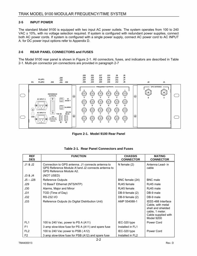
2-5 INPUT POWER The standard Model 9100 is equipped with two input AC power outlets. The system operates from 100 to 240 VAC ± 10%, with no voltage selection required. If system is configured with redundant power supplies, connect both AC power cords. If system is configured with a single power supply, connect AC power cord to AC INPUT A. for DC power input options refer to Appendix D. 2-6 REAR PANEL CONNECTORS and FUSES The Model 9100 rear panel is shown in Figure 2-1. All connectors, fuses, and indicators are described in Table 2-1. Multi-pin connector pin connections are provided in paragraph 2-7
Figure 2-1. Model 9100 Rear Panel
Table 2-1. Rear Panel Connectors and Fuses
REF DES
FUNCTION CHASSIS CONNECTOR
MATING CONNECTOR
J1 & J2 Connection to GPS antenna. J1 connects antenna to GPS Reference Module A1and J2 connects antenna to GPS Reference Module A2.
N female (2) Antenna Lead- in cable
J3 & J4 (NOT USED) J5 – J28 Reference Outputs BNC female (24) BNC male J29 10 BaseT Ethernet (NTS/NTP) RJ45 female RJ45 male J30 Alarms, Major and Minor RJ45 female RJ45 male J31 TOD (Time of Day) DB-9 female (2) DB-9 male J32 RS-232 I/O DB-9 female (2) DB-9 male J33 Reference Outputs (to Digital Distribution Unit) AMP 554088-1 IEEE-488 Interface
Cable, with metal shell and shielded cable, 1 meter. Cable supplied with Model 9200
FL1 100 to 240 Vac, power to PS A (A11) IEC-320 type Power Cord F1 3 amp slow-blow fuse for PS A (A11) and spare fuse Installed in FL1 FL2 100 to 240 Vac power to PSB ( A12) IEC-320 type Power Cord F2 3 amp slow-blow fuse for PSB (A12) and spare fuse Installed in FL2
E1FL1/F1FL2/F2 J33
J29J30J31 J32
J25J26J27J28
J21J22J23J24
J17J18J19J20
J13J14J15J16
J9J10J11J12
J5J6J7J8 J2 J1
FREQUENCY OUTPUTS
123456
A A A A A A
BBBBBB
C C C C C C
DDDDDD
AB
GPS ANTENNA
GND
AC INPUT A
AC INPUT B
REFERENCEOUTPUTS
10BASE T
ALARMS
TODRS-232
I/O
LINE100-240 VAC1.2A TO 0.7A
48-63 Hz
TRAK MODEL 9100 MODULAR FREQUENCY/TIME SYSTEM
2-3 TM4400013 Rev. D
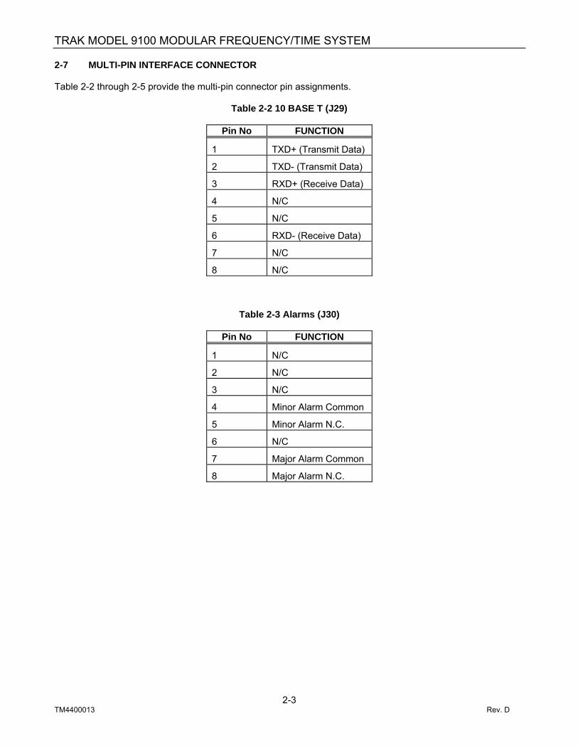
2-7 MULTI-PIN INTERFACE CONNECTOR Table 2-2 through 2-5 provide the multi-pin connector pin assignments.
Table 2-2 10 BASE T (J29)
Pin No FUNCTION
1 TXD+ (Transmit Data)
2 TXD- (Transmit Data)
3 RXD+ (Receive Data)
4 N/C
5 N/C
6 RXD- (Receive Data)
7 N/C
8 N/C
Table 2-3 Alarms (J30)
Pin No FUNCTION
1 N/C
2 N/C
3 N/C
4 Minor Alarm Common
5 Minor Alarm N.C.
6 N/C
7 Major Alarm Common
8 Major Alarm N.C.

TRAK MODEL 9100 MODULAR FREQUENCY/TIME SYSTEM
2-4 TM4400013 Rev. D
Table 2-4 TOD (J31)
Pin No FUNCTION
1 N/C 2 TXD (Transmit Data) 3 N/C 4 N/C 5 Ground 6 N/C 7 N/C 8 N/C 9 N/C
Table 2-5 RS-232 I/O (J32)
Pin No FUNCTION
1 N/C 2 TXD (Transmit Data) 3 RXD (Receive Data) 4 N/C 5 Ground 6 N/C 7 N/C 8 N/C 9 N/C
Table 2-6, Reference Outputs, (J33)
Pin No
FUNCTION
Pin No FUNCTION
1 RS-232 B 13 Ground 2 RS-232 A 14 Ground 3 1 PPS B 15 Ground 4 1 PPS A 16 Ground 5 5 MPPS B 17 Ground 6 5 MPPS A 18 Ground 7 Composite B 19 Ground 8 Composite A 20 Ground 9 GPS Status A 21 GPS Status B 10 I2C Interface Data 22 Ground 11 I2C Interface Clock 23 Ground 12 N/C 24 Ground

TRAK MODEL 9100 MODULAR FREQUENCY/TIME SYSTEM
2-5 TM4400013 Rev. D
2-8 MODULE SET UP Distribution modules have switches or configuration headers for selection of output signals. If known in advance, each system is factory configured for a specific customer application. Otherwise, the modules are set to factory default. Adhesive labels with signal names are provided with each system to attach to the rear panel. This provides a visual indication of the signal selected on the corresponding distribution module. For example if A3 is a DDM and the module is configured for 1 PPS distribution, place the 1 PPS label below BNC connector J8. 2-8.1 DIGITAL DISTRIBUTION MODULE (DDM), (A3-A8) The DDM provide four outputs of the selected reference signal. Each DDM can be set with an internal switch to output four outputs each of the three references. The DDM requires no user adjustments or configuration set-up other than selection of the required reference. Refer to Figure 2-2 for rotary switch location and Table 2-4 for DDM output selector switch settings.
Figure 2-2, DDM Output Selector Switch Location
Table 2-7, DDM Output Signal Switch Positions
SW1 Setting Ref. Output
0 1 PPS 1 Composite 2 5 MPPS
NOTE: Factory default setting for the DDM is 1 PPS.
OUTPUTSELECTSWITCHSETTING
S1 OutputSET 0 1 PPS 1 Composite 2 5 MPPS
SW1
DDM

TRAK MODEL 9100 MODULAR FREQUENCY/TIME SYSTEM
2-6 TM4400013 Rev. D
2-8.2 Model 9107 Frequency Distribution Module (FDM) Module Jumper Settings The FDM provides four outputs of the selected reference signal. Each FDM can be set with internal jumpers on E1 and E2 to output 10 MHz or IRIG B. Refer to Figure 2-3 for jumper location and Table 2-8 for FDM selector output jumper settings. The FDM also has a potentiometer (R2) for adjusting the output signal level of the four outputs. The potentiometer is factory set to 2.8 VPP into 50 ohms.
Figure 2-3, FDM Output Jumper Locations
Table 2-8, FDM Output Signal Jumper Positions
Output Jumper Positions 10 MHz E1, Jumper 1 and 2
E2, Jumper 1 and 2 IRIG-B E1, Jumper 3 and 4
E2, Jumper 3 and 4
E1
1234
E2
1234
R2
IRIG-B, A
IRIG-B, B
10 MHz, A
10 MHz, B
Output LevelTrim Adj.
FDM

TRAK MODEL 9100 MODULAR FREQUENCY/TIME SYSTEM
2-7 TM4400013 Rev. D
2-8.3 Model 9111 TEL Module Switch and Jumper Settings The Model 9111 is factory configured for either T1 or E1 telecommunications outputs and cannot be field changed. This includes both clock and framed signals. Refer to Figure 2-4 for selector switch location and Tables 2-9, 2-10, and 2-11 for TEL selector switch settings. Refer to Tables 2-12 and 2-13 for RS-422 Clock and Framed outputs.
Figure 2-4, TEL Selector Switch and Jumper Location
Model 9111-1 TEL Module Switch and Jumper Settings for T1 Output Ground Isolation (Factory configured)
R33 – R36 Zero Ohm resistors not installed (Isolated)
Clock Select (Factory configured) J3, jumper pins 1 and 2 (1.555 MPPS)
Output Transformer Impedance Select (Factory configured) J5 – J8, jumper 1 and 2 (120Ω)
S11
8
FramingSelect
J3123
123
123
123
123
E1 T1T1 - E1ClockSel.
J5 - J8Output Z
Sel.
J7
J6
J5
J8
TEL

TRAK MODEL 9100 MODULAR FREQUENCY/TIME SYSTEM
2-8 TM4400013 Rev. D
Table 2-9, TEL Framing Format Switch Positions for T1
S1 Settings On Off S1-4 B8ZS Disabled B8ZS Enabled S1-5 Transparent Zero
Suppression Bit 7 Stuffing Zero Suppression
S1-6 Yellow Alarm Transmit Disabled
Yellow Alarm Transmit Enabled
S1-7 193S Select 193E Select S1-8 Internal 193S Bit
Selection External 193S Bit Selection
Table 2-10, TEL Line Length Compensation Switch Positions for T1
S1-1 Settings
S1-2 Settings
S1-3 Settings
Line Length
On Off Off 1 – 133 Feet Off On On 133 – 266 Feet Off On Off 266 - 399 Feet Off Off Off 399 – 533 Feet Off Off Off 533 – 655 Feet
Model 9111 TEL Module Switch and Jumper Settings for E1 Output Ground Isolation (Factory configured)
R33 – R36 Zero Ohm resistors not installed (Isolated), for balanced 120Ω output R33 – R36 Zero Ohm resistors installed (non-Isolated), for unbalanced 75Ω output
Clock Select (Factory configured) J3, jumper pins 2 and 3 (2.048 MPPS)
Output Transformer Impedance Select (Factory configured) J5 – J8, jumper 1 and 2 (120Ω) J5 – J8, jumper 2 and 3 (75Ω)
Table 2-11, TEL Framing Format Switch Positions for E1
S1 Settings On Off S1-4 Transmit CAS
M frame enabled Transmit CAS M frame disabled
S1-5 Transmit CRC4 M frame disabled
Transmit CRC4 M frame enabled
S1-6 Data AMI encoded Data HDB3 encoded S1-7 TDMA normal TDMA alarm enable S1-8 TRA normal TRA alarm enable

TRAK MODEL 9100 MODULAR FREQUENCY/TIME SYSTEM
2-9 TM4400013 Rev. D
Table 2-12, Model 9111 TEL RS-422 Clock Outputs, J1
Pin No
FUNCTION
Pin No
FUNCTION
1 Output A, + 6 Output A, -
2 Output B, + 7 Output B, -
3 Output C, + 8 Output C, -
4 Output D, + 9 Output D, -
11- 15 Ground 5-10 No Connection
Table 2-13 Model 9111 TEL Framed Outputs, J2
Pin No
FUNCTION
Pin No FUNCTION
1 Output A, + 6 Output A, -
2 Output B, + 7 Output B, -
3 Output C, + 8 Output C, -
4 Output D, + 9 Output D, -
11- 15 Ground 5-10 No Connection

TRAK MODEL 9100 MODULAR FREQUENCY/TIME SYSTEM
3-1 TM4400013 Rev D
CHAPTER 3
OPERATION 3-1 GENERAL This chapter covers the operation of the Model 9100 including a description of front and rear panel controls and indicators, initial synchronization, fault detection and remote interfaces. 3-2 FRONT PANEL CONTROLS and INDICATORS A typical Model 9100 front panel view is shown in Figure 3-1. This view depicts a typical system configured for redundant operation.
Figure 3-1. Typical Model 9100- Front Panel View The Model 9100 has 12 front panel plug-in module locations. A1 and A2 are reserved for the GPS Reference Modules, A3 through A8 are reserved for distribution modules, A9 and A10 are reserved for FSU modules and A11 and A12 are reserved for Power Supply modules. In non-redundant configurations, GPS Reference module A2 and Power Supply module A12 are omitted. The type and number of distribution modules installed in module locations A3 through A8 vary based on system application. A view of each module front panel along with a description of controls and indicators are provided below.
A1 A2 A3 A4 A5 A6 A7 A8 A9 A10 A11 A12
FAULT
TRAKSYSTEMS
INPUT
OUT A
OUT B
OUT C
OUT D
FDM
FAULT
TRAKSYSTEMS
FSU
AUTO
B
A
PRESSTO
RESET
ON LINE
STANDBY
FAULTRESET
SELECT
TRAK Systems
GPS REFERENCE
FAULT
TRAKSYSTEMS
ON LINE
STANDBY
LOCKED
TRACKING
1 PPS
5 MPPS
COMPOSITE
IRIG B
GND
GPS
GPS REFERENCE
FAULT
TRAKSYSTEMS
ON LINE
STANDBY
LOCKED
TRACKING
1 PPS
5 MPPS
COMPOSITE
IRIG B
GND
GPS
OUT A
OUT B
OUT C
OUT D
FAULT
TRAKSYSTEMS
DDM
OUT A
OUT B
OUT C
OUT D
FAULT
TRAKSYSTEMS
DDM
OUT A
OUT B
OUT C
OUT D
FAULT
TRAKSYSTEMS
DDM
OUT A
OUT B
OUT C
OUT D
FAULT
TRAKSYSTEMS
DDM TEL
FAULT
TRAKSYSTEMS
FRAMED
RS-422
TRAKSYSTEMS
AC/DC P.S.
FAULT
+5VDC+15VDC
-15VDC
TRAKSYSTEMS
AC/DC P.S.
FAULT
+5VDC+15VDC
-15VDC

TRAK MODEL 9100 MODULAR FREQUENCY/TIME SYSTEM
3-2 TM4400013 Rev D
3-2.1. GPS Reference Modules, A1 and A2 The Model 9101 GPS Reference Module front panel is shown in Figure 3-2. Descriptions of the indicators and test points are given below.
FAULT Red, module fault summation ON LINE Green, indicates module is the on line reference STANDBY Green, indicates module is in standby LOCKED Green, indicates internal oscillator is within ± 400 ns of GPS. At power up and until the
module is locked the indicator flashes, during this time the 1 PPS, 5 MPPS and Composite signal outputs are muted.
TRACKING Green, indicates GPS is tracking satellites
The Model 9101 GPS Reference Module front panels shown in Figure 3-2 contains the following test points:
1 PPS Module 1 PPS monitor 5 MPPS Module 5 MPPS monitor COMPOSITE Module Composite monitor IRIG-B Module IRIG-B modulated time code monitor GND Ground
Figure 3-2. Model 9101 GPS Reference Module (GPS)
NOTE: GPS Reference modules that contain a front panel fan have an internal Rubidium oscillator. Modules without the fan contain a crystal oscillator.
GPS REFERENCE
FAULT
TRAKSYSTEMS
ON LINE
STANDBY
LOCKED
TRACKING
1 PPS
5 MPPS
COMPOSITE
IRIG B
GND
GPS
GPS REFERENCE
FAULT
TRAKSYSTEMS
ON LINE
STANDBY
LOCKED
TRACKING
1 PPS
5 MPPS
COMPOSITE
IRIG B
GND
GPS

TRAK MODEL 9100 MODULAR FREQUENCY/TIME SYSTEM
3-3 TM4400013 Rev D
3-2.2 Digital Distribution Module The Model 9106 (DDM) front panel shown in Figure 3-3 contains a FAULT indicator and four output test points. The FAULT illuminates when one or more of the four outputs fail. The FAULT indication is latched until cleared by “FAULT RESET” switch on the front panel of the FSU. The output test points allow monitoring of selected outputs from the front panel.
Figure 3-3. Model 9106 Digital Distribution Module (DDM)
OUT A
OUT B
OUT C
OUT D
FAULT
TRAKSYSTEMS
DDM

TRAK MODEL 9100 MODULAR FREQUENCY/TIME SYSTEM
3-4 TM4400013 Rev D
3-2.3 Telecommunications Signal Generator Module The Model 9111 (TEL) front panel shown in Figure 3-4 contains a FAULT indicator and two 15 pin “DD” connectors, one for RS-422 telecom clock and the other for telecom framed outputs The FAULT illuminates when an output fails. The FAULT indication is latched until cleared by “FAULT RESET” switch on the front panel of the FSU.
Figure 3-4. Model 9111 Telecom Signal Generator Module (TEL)
TEL
FAULT
TRAKSYSTEMS
FRAMED
RS-422

TRAK MODEL 9100 MODULAR FREQUENCY/TIME SYSTEM
3-5 TM4400013 Rev D
3-2.4 Frequency Distribution Module (FDM) The Model 9107 (FDM) front panel shown in Figure 3-5 contains a FAULT indicator, input test point and four output test points. The FAULT illuminates when one or more of the four outputs fail. The FAULT indication is latched until cleared by “FAULT RESET” switch on the front panel of the FSU. The input and output test points allow monitoring of selected outputs from the front panel.
Figure 3-5. Model 9107 Frequency Distribution Module (FDM)
FAULT
TRAKSYSTEMS
INPUT
OUT A
OUT B
OUT C
OUT D
FDM
TRAK MODEL 9100 MODULAR FREQUENCY/TIME SYSTEM
3-6 TM4400013 Rev D
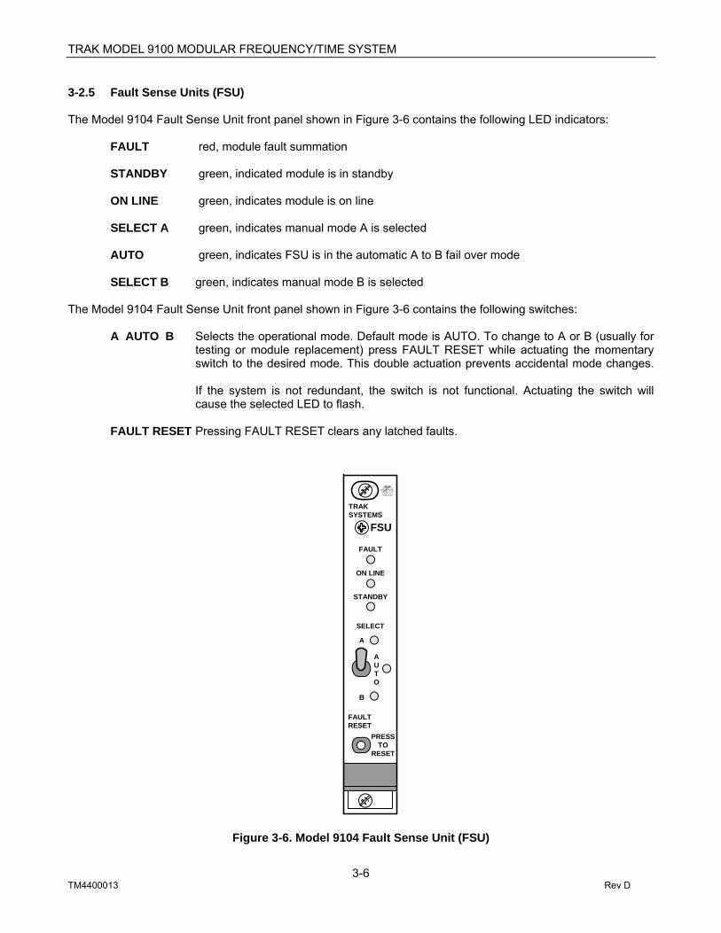
3-2.5 Fault Sense Units (FSU) The Model 9104 Fault Sense Unit front panel shown in Figure 3-6 contains the following LED indicators:
FAULT red, module fault summation STANDBY green, indicated module is in standby
ON LINE green, indicates module is on line
SELECT A green, indicates manual mode A is selected AUTO green, indicates FSU is in the automatic A to B fail over mode SELECT B green, indicates manual mode B is selected The Model 9104 Fault Sense Unit front panel shown in Figure 3-6 contains the following switches:
A AUTO B Selects the operational mode. Default mode is AUTO. To change to A or B (usually for testing or module replacement) press FAULT RESET while actuating the momentary switch to the desired mode. This double actuation prevents accidental mode changes. If the system is not redundant, the switch is not functional. Actuating the switch will cause the selected LED to flash.
FAULT RESET Pressing FAULT RESET clears any latched faults.
Figure 3-6. Model 9104 Fault Sense Unit (FSU)
FAULT
TRAKSYSTEMS
FSU
AUTO
B
A
PRESSTO
RESET
ON LINE
STANDBY
FAULTRESET
SELECT

TRAK MODEL 9100 MODULAR FREQUENCY/TIME SYSTEM
3-7 TM4400013 Rev D
3-2.6 Power Supplies, A11 and A12 The Model 9120 Power Supply front panel shown in Figure 3-7 contains a red FAULT indicator and three green power supply output voltage status indicators. The FAULT indicator illuminates if any of the three power supply voltages drop below a set level. The appropriate green power supply indicators are normally illuminated and will extinguish if the voltage is out of range.
Figure 3-7. Model 9120 Power Supply
TRAKSYSTEMS
AC/DC P.S.
FAULT
+5VDC+15VDC
-15VDC

TRAK MODEL 9100 MODULAR FREQUENCY/TIME SYSTEM
3-8 TM4400013 Rev D
3-3 INITIALSYNCHRONIZATION With all signal connections made, antenna(s) installed, connected and power applied, the Model 9100 automatically performs initial synchronization. No operator intervention is necessary other than setting the antenna cable delay, if different than the factory setting of 65 nanoseconds. Antenna cable delay can be changed through the RS-232 interface using the SDC command. Propagation delay for common cable type is provided in Table 2 of Appendix E.
Warning: Connecting the antenna(s) to the Model 9100 after power is applied may cause the GPS receiver to take longer than normal to acquire satellites. If power is applied without antenna(s) connected for greater than 1-hour, it is recommended that power be cycled to allow the GPS receiver to perform normal satellite search.
At power up and for 20 to 45 minutes, the system front panel LEDs provide indication of the initialization stages. These are the sequence of events and that occur. a. All Power Supply green LEDS should be illuminated. b. All FSU LEDs illuminate for 5 seconds, then the AUTO LED remains on and all others off, indicating
initialization of the FSU is complete. c. The GPS REF modules FAULT, ONLINE and STANDBY LED illuminate for 20 seconds, then the FAULT,
ON LINE, and STANDBY LEDS of the GPS REF modules go out, indicating CPU initialization of the GPS REF modules is complete.
d. Once the GPS REF module is initialized the LOCKED LED flashes until the GPS receiver acquires
satellites, oscillator warm-up is complete, and 1 PPS phase is within ± 400 nanoseconds of the GPS 1 PPS. The TRACKING LED will normally illuminates within 5 to 10 minutes after power up. The module is operational when the LOCKED LED remains ON. This normally takes 20 to 45 minutes.
NOTE: While the LOCKED LED flashes the 1 PPS, 5 MPPS and Composite outputs of the GPS
REF module are muted. If redundant GPS REF modules are installed and the backup GPS REF locks first it will be placed on line until the primary module locks.

TRAK MODEL 9100 MODULAR FREQUENCY/TIME SYSTEM
3-9 TM4400013 Rev D
3-4 TOD OUTPUT The Model 9100 provides an ASCII time of day (TOD) output message that is output once per second. Two formats are available and are selected through the RS-232 I/O or 10 BASE T using the SCM command. Refer to section 3-5 for description of this command. 3-4.1 Time Format 1 Time is output once per second from the TOD output port in the following format:
TYYYY,MM,DD,HH:mm:SS,F<CR/LF> Where: T = Start of string (RS-232 positive going edge of the start bit that comprises the ASCII “T” is the “on-time mark”). YYYY = Year MM = Month of year DD = Day of month HH = Hours of day mm = Minutes of hour SS = seconds of minute F = Time Figure of Merit (TFOM), “0” when time is unknown or > 1μs and “4” when time is valid and < 1μs. CR/LF = Carriage return/Line feed
3-4.2 Time Format 2 Time is output once per second from the TOD output port in the following format:
<CR/LF>FspspDDDspHH:MM:SSspDsTZ=xx<CR/LF>
Where: First CR/LF = Start of string (RS-232 positive going edge of the start bit that comprises the first ASCII “CR” is the “on-time mark”). F = TFOM, “Space” when time is valid and < 1μs, “?” when time is unknown or > 1μs, or “*” when in holdover mode spsp = space space DDD = Day of year sp = space HH = Hours of day MM = Minutes of hour SS = seconds of minute sp = space Ds = Daylight savings, “S” during periods of standard time for selected DST schedule, “I” for 24 hour preceding DST, “D” DST, and “O” for 24 hour period after DST TZ = Time zone xx = time zone number (Example: Eastern time zone is 05. Pacific is 08)

TRAK MODEL 9100 MODULAR FREQUENCY/TIME SYSTEM
3-10 TM4400013 Rev D
3.5 REMOTE OPERATION The Model 9100 can be setup and monitored remotely through the RS-232 I/O or 10 BASE T using TELNET. There are two modes that can be set; one is the “Local Echo” mode where each character that is input is echoed back to the host. The second is the “Computer” mode where the input characters are not echoed. The “computer” is the default mode. 3-5.1 Computer Mode The Computer Mode is the default mode of RS-232 communications port and is used when controlling the Model 9100 from a remote computer. No echoing of input commands is given, and the once-per-second time output, if commanded, is active, when enabled. When writing interface programs, do not issue three or more successive carriage return <CR> commands. This will switch the port communications mode to Local Echo. To reenter the Computer Mode after using the Local Echo mode, issue a control <^E>. 3-5.2 Local Echo Mode Use this mode when controlling the Model 9100 from a terminal program such as Hyper Terminal. Enter the Local Echo Mode by typing three successive carriage returns <CR>. 9100> prompt is displayed in this mode, and all input key strokes are echoed to the screen. While in the Local Echo mode, once-per-second time outputs from this port are suspended. To exit this mode, type a control E <^E>.
NOTE
Before attempting to use the RS-232 port, assure that the remote computer or terminal is set to 9600
baud, 8 data bits, 1-stop bit and no parity.
3-5.3 Remote Interface Commands The following section contains a list and description of all remote interface commands. Request commands are prefixed with “RQ” and return status. Setup commands are prefixed with ”S” and allow system parameter changes by writing data in the parameter field. All commands are initiated from the host computer. All entries must be terminated with a carriage return <CR>. The Model 9100 will respond with a <CR> and a <LF>. The setup commands will reply with the command and “DONE” if the command and the data received is valid. If the command or data is not valid, the command replies with the setup command that was issued and “ERROR”. Setup commands can also be used for status if no data is sent. Commands can be directed to a specific GPS Reference module. These commands are prefixed with an “X”, where “X” is an “A” for the primary GPS Reference module and “B” for the backup GPS Reference module. Omitting the “X” prefix will cause different results, depending on the command is being used in the setup mode or request mode. If the “X” prefix is omitted, and the command is in the request mode, it will be directed to the on-line module. If the “X” prefix is omitted, and the command is in the set mode, it will be directed to both modules. The response will always contain the “X” parameter, indicating which module responded to the command. If the response is caused by a command that was sent to both modules, the “X” parameter will be ‘D’. Commands that have this capability are prefixed with an “X” in the command description.

TRAK MODEL 9100 MODULAR FREQUENCY/TIME SYSTEM
3-11 TM4400013 Rev D
Examples of remote interface command. 1. Request time mode from primary GPS Reference module using the STM command.
Host sends: A.STM <CR> 9100 replies: A.STM U <CR><LF>
2. Request time mode from backup GPS Reference module using the STM command.
Host sends: B.STM <CR> 9100 replies: B.STM U <CR><LF>
3. Set Time mode to UTC on primary and backup GPS Reference modules
Host sends: STM U <CR> 9100 replies: D.STM DONE <CR><LF>
A list of available request status commands and setup commands with descriptions and factory default parameters are provided in Table 3-1 and 3-2 respectively.

TRAK MODEL 9100 MODULAR FREQUENCY/TIME SYSTEM
3-12 TM4400013 Rev D
Table 3-1 Request Commands List
COMMAND DESCRIPTION DEFAULT
X.RQDR Request oscillator DAC value N/A X.RQIR Request difference between internal 1 PPS and
selected time reference N/A
X.RQLK Request 1 PPS reference locked status N/A X.RQLN Request navigation solution N/A X.RQLS Request Leap Second Status N/A X.RQST Request list of satellites being tracked N/A X.RQBT Request GPS Reference module bit status N/A X.RQSD Request Currently Visible Satellite Position and
Tracking Status and Dilution of Precision (DOP) N/A
RQFS Request fault status Off RQSW Request software version and compile data N/A
Table 3-2 Setup Commands List
COMMAND DESCRIPTION DEFAULT
SCM 1, 2 Set time mode to Time Format 1 or 2 Time Format 1 X.SDC Set and request user and antenna delay
compensation. 0 ns user delay 65 ns antenna delay
X.SDD Set and request spring and fall dates for daylight savings and standard times.
Spring Date: 4/1 Fall DATE: 10/28
X.SLP Set and request user entered position N/A X.SPS Set and request position source Computed average
position X.SUT Set UTC time and request current time. N/A X.STM Set and request time mode. UTC X.STI Set and request receiver unlock time-out delay 5 days RUB
2 days DXTL SOS Switch on-line source AUTO FRST Remote fault reset N/A

TRAK MODEL 9100 MODULAR FREQUENCY/TIME SYSTEM
3-13 TM4400013 Rev D
3-5.4 Request Commands Request DAC reference value Indicates the voltage level which when applied to the internal oscillator control input will place the oscillator at its' 10 MHz center frequency. This value is used to indicate when the oscillator needs calibration. If the DAC value is < 6,554 or >58,982 the OSC CAL minor alarm is activated. Host sends: X.RQDR<CR> 9100 replies: X.RQDR ddddd<CR><LF> Where: ddddd is DAC setting (range is 0 to 65535) X is described on command summary page NOTE: The ddddd field is not padded with zeros or spaces and will contain only the digits necessary to represent the value. Request difference between the internal 1 PPS reference and the selected time reference Host sends: X.RQIR<CR> 9100 replies: X.RQIR ttt REF – mmm, "string"<CR><LF> Where: ttt (time ref) is "INT" if internal reference
mmm (measurement ref) is "UTC" or "GPS" "string" is either the difference (in nanoseconds) or a status message X is described on command summary page Request internal 1 PPS reference locked status Provides time stamp of when internal oscillator locked or unlocked. Host sends: X.RQLK<CR> 9100 replies: X.RQLK NO LOCK SINCE POWERUP<CR><LF> or X.RQLK FREE RUN SINCE ddd:hh:mm:ss<CR><LF> or X.RQLK LOCKED SINCE ddd:hh:mm:ss<CR><LF> Where: X is described on command summary page
TRAK MODEL 9100 MODULAR FREQUENCY/TIME SYSTEM
3-14 TM4400013 Rev D
Request navigation solution being received from GPS receiver NOTE: The position returned from this request is the position the GPS receiver is using to output precise time. If the position source is “NA” or “N”, the position returned from this command will update every second until the new position computed by the receiver. If the position source is “U” or “A”, the receiver will then return either the user input or the average position respectively. Host sends: X.RQLN <CR> 9100 replies: X.RQLN dd:mm.fffN,ddd:mm.fffW,Shhhhh.f<CR><LF> Where: dd:mm.fffN is Latitude, where N is North or S is South ddd:mm.fffW is Longitude, where W is West or E is East Shhhhh.f is signed Height in meters X is described on command summary page Request leap second status This command provides date of the next pending leap second. If no leap second is scheduled, the data are all zeros. (Data is automatically down loaded from GPS). Host sends: X.RQLS<CR> 9100 replies: X.RQLS yy,mm,dd<CR><LF> Where: yy = year; e.g. (two digit year) mm = month dd = day of month X is described on command summary page Request Currently Visible Satellite Position and Tracking Status and Dilution of Precision (DOP) Values - Host sends: X.RQSD <CR> 9100 replies: X.RQSD PRN sv, AZ=AAA, EL=EE, SN=SS.S,TRK=t<CR><LF> X.Current DOP = DDD.D<CR><LF> where: sv is the satellite number AAA is the azimuth in degrees EE is the elevation is degrees SS.S is the signal to noise ratio T is the tracking status (“Y”= tracking, “N”= not tracking) DDD.D is the PDOP in 3D fix HDOP in 2D fix or 00 in position hold mode (DOP = dilution of precision) X is described on command summary page
The “RQSD” line is repeated for each satellite currently visible up to a maximum of 12 satellites. In addition,
each comma is followed by a space character.

TRAK MODEL 9100 MODULAR FREQUENCY/TIME SYSTEM
3-15 TM4400013 Rev D
Request list of satellites being tracked – This command provides the PRN numbers of the satellites being tracked. Host sends: X.RQST<CR> 9100 replies: X.RQST sv,sv,sv,sv,sv,sv,sv,sv,sv,sv,sv,sv<CR><LF> or X.RQST NONE<CR><LF> Where: sv is the satellite PRN number X is described on command summary page NOTE: The “X.RQST sv” line is shown in its longest form. The actual response length will vary depending on the number of satellites being tracked at the time. Request GPS Reference Module BIT Status This command provides the BIT status of the GPS Reference module. Host sends: X.RQBT<CR> 9100 replies: X.GPS BIT STATUS ABCDEFGHIJ
Where: A is GPS status, G or F B is GPS Rubidium Lock and 10 MHz Status, G or F C is GPS 5 MHz status, G or F D is GPS Composite Status, G or F E is GPS IRIG-B status, G or F F is GPS 1 PPS status, G or F G is GPS CPU status, G or F H is GPS Antenna status, G or F I is GPS oscillator calibration or DAC failure, G or F J is GPS on-line status, Y or N
X is described on command summary page

TRAK MODEL 9100 MODULAR FREQUENCY/TIME SYSTEM
3-16 TM4400013 Rev D
Request Fault Status This command provides system BIT status information. The status can be quarried or automatically output with a change in status. Request Mode Host sends: RQFS<CR> 9100 replies: FSU AB GPS CDEFGHIJKL PWR M DST NOPQ <CR/LF>
Where: A is CPU status of the FSU, G or F (Good or Fail) B is On-line status of the FSU, A or B C is GPS status, G or F D is GPS Rubidium Lock and 10 MHz Status, G or F E is GPS 5 MHz status, G or F F is GPS Composite Status, G or F G is GPS IRIG-B status, G or F H is GPS 1 PPS status, G or F I is GPS CPU status, G or F J is GPS Antenna status, G or F K is GPS oscillator calibration or DAC failure, G or F L is GPS on-line status, A, B, or M (both A and B muted) M is Power Supply status, G or F N is Distribution Frequency output status, G of F O is Distribution TEL output status, G or F P is Distribution TTL output status, G or F Q is Distribution TFL status, G or F
Set Mode: Host sends: RQFS string <CR> Where: string is ON to enable automatic output of the above message when a change
in status is detected. String is OFF to disable automatic output 9100 replies: RQFS DONE <CR><LF> Request software version and compile date-
Host sends: RQSW<CR>
9100 replies: FSU: A Date: Ver: Slot 1: Date: Ver:
Slot 2: Date: Ver: Slot 3: Date: Ver: Slot 4 Date: Ver: Slot 5: Date: Ver: Slot 6: Date: Ver: Slot 7: Date: Ver: Slot 8: Date: Ver:

TRAK MODEL 9100 MODULAR FREQUENCY/TIME SYSTEM
3-17 TM4400013 Rev D
3-5.4 Request / Setup Commands Set/Request Time Format 1 or Time Format 2 This command sets or requests the time format of the TOD output port. Request mode: Host sends: SCM <CR> 9100 replies: TIME FORMAT X <CR><LF> Where: X is 1 for Time Format 1 X is 2 for Time Format 2 Set mode: Host sends: SCM 1 <CR> (For Time Format 1 (see para. 3-4.1) SCM 2 <CR> (For Time Format 2 (see para. 3-4.2) 9100 replies: SCM Done Set/Request user offset and antenna delay compensation This command provided the user to offset the GPS 1 PPS reference for antenna delay compensation and to offset the GPS 1 PPS from UTC. Request mode: Host sends: X.SDC<CR> 9100 replies: X.SDC suuuuuuuuu,aaaaaa<CR><LF> Where: suuuuuuuuu is the signed user offset in nanoseconds up to 500000000ns aaaaaa is the antenna delay compensation in nanoseconds up to 999999ns X is described on command summary page Set mode: Host sends: X.SDC suuuuuuuuu,aaaaaa<CR> 9100 replies: X.SDC DONE<CR><LF> Where: Same as for SDC request mode WARNING: Time accuracy is degraded if incorrect offset or antenna delay compensation is entered.

TRAK MODEL 9100 MODULAR FREQUENCY/TIME SYSTEM
3-18 TM4400013 Rev D
Set/Request DST dates This command enters the day light savings time (DST) Spring and Fall change dates. Refer to Table 3-2 for factory default dates. Local standard time may be selected when DST is not used. Request mode: Host sends: X.SDD<CR> 9100 replies: X.SDD mm,dd,mm,dd,M<CR><LF> Where: 1st mm,dd - is Spring's date and 2nd mm,dd - is Fall's date M is a "D" if daylight or an "S" if standard X is described on command summary page. Set mode: Host sends: X.SDD mm,dd,mm,dd,M<CR> 9100 replies: X.SDD DONE<CR><LF> Where: Same as for SDD request mode. Set/Request local position The position entered with this command may be used in two ways. If the position source is “N” or “NA”, the GPS receiver will accept and use the entered position, but will update it as navigation solutions are computed; if the position source is “U”, the entered position will be used and no position solutions will be performed. If the position source is “A”, the entered position will not be used, but will be stored for later retrieval should the user decide to change the position source. Refer to SPS command for further clarification of when this command is used. Warning: Entering an incorrect position will degrade the GPS REF module timing accuracy and in some cases, the GPS will cease satellite tracking. Request mode: Host sends: X.SLP<CR> 9100 replies: X.SLP dd:mm.fffN,ddd:mm.fffW,Shhhhh.f<CR><LF> Where: dd:mm.fff is Latitude (N is North or S is South) ddd:mm.fff is Longitude (W is West or E is East) Shhhhh.f is signed Height in meters X is described on command summary page Set mode: Host sends: X.SLP dd:mm.fffN,ddd:mm.fffW,Shhhhh.f<CR> 9100 replies: X.SLP DONE<CR><LF> Where: Same as for SLP request mode.

TRAK MODEL 9100 MODULAR FREQUENCY/TIME SYSTEM
3-19 TM4400013 Rev D
Set/Request position source Average position is the default mode and should be used for most applications. This mode performs an average of 10,000 2D or 3D position fixes. If the averaging is interrupted, the averaging resumes where it left off when tracking is resumed. Once the averaging is complete, the GPS receiver automatically enters position hold mode and the average position latitude, longitude and height is stored in NV memory. On subsequent power up a mini-average is computed and if the mini-average passes a GPS receiver is placed in Position Hold mode with the antenna position that was saved in NV memory. If the position source is changed to “N” or “U” during an average, the averaging operation will be halted and reset. All averaging data will be erased and the GPS satellite tracking will cease and reacquire. If the user changes the position source to “U”, the unit will enter this mode on the next power-up and will not perform an average position operation. User Position mode should only be used if an accurate antenna survey is known. If the GPS receiver is set to User Position with a wrong position will cause degraded time accuracy and in some cases, the GPS will cease satellite tracking. However, if the GPS is powered up in User Position a mini-site survey is performed. If the mini-site survey fails, the GPS receiver is automatically placed in Average Position mode. The Navigation mode should only be used on moving platforms. In this mode, the time accuracy is degraded. Warning: Timing accuracy is degraded in Navigation mode or in User Position with the incorrect position entered in the SLP command. Request mode: Host sends: X.SPS<CR> 9100 replies: X.SPS m<CR><LF> Where: m - is an "N" if the receiver navigation solution is selected m - is a "NA" if the computed average position is selected and the average position computation is not complete m - is a "A" if the computed average position is selected and the average position computation has completed m - is an "U" if the user entered position is selected X is described on command summary page Set mode: Host sends: X.SPS m<CR> Where: m - is an "N" if use of the receiver navigation solution is desired m - is a "A" if use of the computed average position is desired m - is an "U" if use of the user entered position is desired X is described on command summary page 9100 replies: X.SPS DONE<CR><LF>

TRAK MODEL 9100 MODULAR FREQUENCY/TIME SYSTEM
3-20 TM4400013 Rev D
Set/Request time mode This command selects GPS, UTC or Local for all time outputs in the unit. Hours and minutes offset between time zones can be entered. If GPS is selected, the offset between GPS and UTC is updated automatically when the unit tracks satellites. Any changes to these parameters should be made after power-up and before antenna position averaging takes place. Warning: UTC is the default time mode and is normally used in most applications. If the time mode is
change to local or GPS, the IRIG B, TOD port and optional NTS will output time in the selected mode.
Request mode: Host sends: X.STM<CR> 9100 replies: X.STM t,ooo,mm<CR><LF> Where: t is a "G" if GPS t is a "U" if UTC t is a "L" if LOCAL ooo is the signed offset value in hours (±HH) for Local mm is the offset in minutes (00-59) for Local X is described on command summary page Set mode: Host sends: X.STM t,ooo,mm<CR>
9100 replies: X.STM DONE<CR><LF> Where: Same as for STM Request mode
Note: The minor time mode is set to UTC if UTC or LOCAL are selected and GPS if GPS is selected. It is not necessary to enter the hours and minutes offset when switching to LOCAL time. The unit will use the last entered offset values if none are specified.

TRAK MODEL 9100 MODULAR FREQUENCY/TIME SYSTEM
3-21 TM4400013 Rev D
Set/Request receiver unlock time-out delay - This command provides a user settable time out that will mask an unlock (holdover) condition from causing a GPS REF module failure until the time out elapses. The time out is set in hours and days and if the STI is requested while the GPS REF module is locked, the response will contain the user setting. However, if the GPS REF module is in holdover, the STI responds with the user set timeout and the current minutes, hours and days left for the timeout to elapse. If the timeout elapses, the GPS REF module will indicate a failure. Request mode: Host sends: X.STI<CR> 9100 replies: X.STI dd:hh<CR><LF> (if in non-holdover mode)
X.STI dd:hh DD:HH:MM <CR><LF> (if in holdover mode, elapsed time of holdover)
Where: dd is the time-out in days, user set time out hh is the time-out in hours, user set time out DD is the number of days left before timeout elapses if in holdover HH is the number of hours left before the timeout elapses if in holdover MM is the time out in minutes left before the timeout elapses if in holdover X is described on command summary page Set mode: Host sends: X.STI dd:hh <CR> 9100 replies: X.STI DONE<CR><LF> Where: Same as for STI request mode

TRAK MODEL 9100 MODULAR FREQUENCY/TIME SYSTEM
3-22 TM4400013 Rev D
Set/Request UTC time - (Optional). This command is never required but is provided to allow the unit to be used as a time code generator, without the need of a satellite. This command can also be used to request the current time. Warning: Time can not be set if GPS REF module is tracking satellites. Request mode: Host sends: X.SUT<CR> 9100 replies: X.SUT ddd:hh:mm:ss.ff0,Q<CR><LF> Where: ddd is day of year hh is hours mm is minutes ss is seconds ff0 is milliseconds with 10 ms resolution Q is Quality byte
0 = Unknown 4 = Phase < 1uS
X is described on command summary page Set mode: Host sends: X.SUT yyyy,MM,dd,hh,mm,ss<CR> 9100 replies: X.SUT DONE <CR><LF> Where: yyyy is year; e.g. 1991 MM is month dd is day of month others fields are as previously described

TRAK MODEL 9100 MODULAR FREQUENCY/TIME SYSTEM
3-23 TM4400013 Rev D
Set/Request On-line source In request mode, this command provides the status of the FSU front panel SELCT switch. In set mode the command duplicates the front panel selection. Warning: If changing the setting from “T” to “A” or “B” will override the automatic switchover function. Request mode: Host sends: SOS<CR> 9100 replies: SOS S<CR><LF> Where: S is T for auto S is A for source A S is B for source B Set mode: Host sends: SOS S<CR> 9100 replies: SOS DONE<CR><LF> Where: Same as for SOS request mode Fault Reset command This command will attempt to clear any Model 9100 latched failures. Set mode: Host sends: FRST <CR> 9100 replies: FRST DONE<CR><LF>

TRAK MODEL 9100 MODULAR FREQUENCY/TIME SYSTEM
4-1 TM4400013 REV. D
CHAPTER 4
Maintenance 4-1 GENERAL The Model 9100 provides maintenance-free operation for the life of the system. This chapter contains instructions for locating and correcting failures in the Model 9100 MFTS. Troubleshooting instructions are provided for locating and replacing modules. No troubleshooting aids are provided beyond the module level. 4-2 MAINTENANCE PHILOSOPHY All circuits in the Model 9100 are in front-panel replaceable modules, allowing rapid repair at the system operational level. Additionally, all modules contain fault indicators, allowing rapid recognition and replacement of a failed module. No attempt should be made to repair a module. These assemblies should be returned to the factory for repair. 4-3 PREVENTATIVE MAINTENANCE Preventive maintenance of the system consists mainly of cleaning and general inspection to maintain the best environment for the equipment operation. Power Supplies and GPS Reference modules contain fans; these modules should be periodically cleaned to remove any dust buildup. 4-4 REPLACEMENT of MODULES All modules are “hot-swappable”, however, the power supply module swapping should be limited to those times when disruption of power would cause problems in the main system. A procedure for Power Supply replacement is provided in Paragraph 4-5.3. 4-5 TROUBLE SHOOTING GUIDE The following paragraphs provide corrective actions for system failures. Included are procedures for fault recognition, failed module location, and for module replacement.

TRAK MODEL 9100 MODULAR FREQUENCY/TIME SYSTEM
4-2 TM4400013 REV. D
4-5.1 GPS Reference Failure If a primary or backup GPS Reference module fails, the red front-panel FAULT indicator lights. Before replacing a failed GPS module, verify the following: 1. Through the RS-232 I/O or optional 10BaseT port, identify the failure by issuing the RQBT command to
collect the BIT status of the failed module. Refer to the RQBT message response below for description of message response.
2. If the failure is due to the GPS Receiver BIT, or the antenna BIT, check the following. For any other failures
the module must be replaced and sent back to the factory for repair.
A. Perform continuity test of antenna cable and verify the cable is not open or shorted. B. Antenna is mounted vertically and above obstructions that prevent clear view of the sky. C. Antenna cable connectors are secure and if lightning arrestor is used, verify it is installed according
to manufacturer’s instructions. D. Antenna cable is within the minimum and maximum length. Refer to Appendix E, Table 2 for the
proper antenna cable lengths. E. If the Model 9100 has redundant GPS REF modules, swap antenna inputs A and B, and verify if the
failure in the failed GPS REF module clears. If it does the replace the antenna. X.RQBT<cr><lf> Module returns: GPS BIT STATUS ABCDEFGHIJ <cr><lf> Where: A is GPS Receiver BIT (G = Good, F = Fail)
B is Rub lock or 10 MHz BIT (G = Good, F = Fail) C is 5 MHz BIT (G = Good, F = Fail) D is Composite BIT (G = Good, F = Fail) E is IRIG B BIT (G = Good, F = Fail) F is 1PPS BIT (G = Good, F = Fail) G is CPU BIT (G = Good, F = Fail) H is Antenna BIT (G = Good, F = Fail) I is Oscillator cal (G = Good, F = Fail) (F will not cause the front panel LED to light, unless DAC failure is detected or DAC reaches its limit of adjustment) J is Module online Y = Yes, N = No)
If it’s determined that a module has failed, follow the instructions below for replacement. a) Place the FSU Online switch to the non-failed position. For example, if the primary GPS Reference is being
replaced set the FSU A/AUTO/B switch to position B.
b) Loosen the four panel screws securing the module to the chassis.
c) Push down on the ejector handle to disengage the module and carefully pull on handle to withdraw module from chassis.
d) Install the new GPS module and secure to chassis by tightening the four front panel screws.
e) At the FSU front panel, depress the FAULT RESET switch and assure that all fault indicators are extinguished.
f) Allow a minimum of 10 minutes for the GPS Reference module(s) to track satellites and an additional 30 minutes to 1 hour for the module to lock. This can be verified by viewing front panel TRACKING and LOCKED indicators.
g) Place the FSU Online switch back to the AUTO position.

TRAK MODEL 9100 MODULAR FREQUENCY/TIME SYSTEM
4-3 TM4400013 REV. D
4-5.2 Distribution Failures The Model 9100 may contain DDM, FDM and TEL distribution modules. If any of the modules fail, the front panel indicator of the failed module will illuminate. Before replacing the failed module, verify the following:
1. Remove all the cables connected to the failed module and depress the FSU “FAULT RESET” switch. If the “FAULT” indicator of the module is cleared, the problem may be a shorted cable, failure at the receiving end of the cable, or the cable is not properly terminated.
2. If the failure persists, replace the failed module as follows: a) Loosen the two screws securing the failed module to the chassis.
b) Push down on the ejector handle to disengage the module and carefully pull on handle and withdraw module from chassis.
c) Note the configuration of the failed module and configure the replacement module accordingly.
d) Install the new module and secure to chassis by tightening the two front panel screws.
e) Depress the FAULT RESET switch and assure that the FAULT indicator is extinguished.
4-5.3 Power Supply Failure The Model 9100 contain AC/DC Power Supplies or optional DC/DC Power Supplies. If a Power Supply module fails, the fault indicator of the failed module illuminates. Before replacing the failed module verify the following:
1. Correct input voltage is connected to the rear panel AC or DC input. 2. Rear panel Fuse is not open.
Warning: Power Supplies should not be inserted with power applied To replace a failed Power Supply Module proceed as follows: a) Remove AC power to the failed power supply. For example if the Power Supply module closest to the FSU
failed, remove power cord on rear panel labeled AC INPUT A. If Power Supply module closest to the edge of the chassis failed, remove power cord on rear panel labeled AC INPUT B.
b) Before removing a failed Power Supply module, check to see if the fuse located on the filter fuse assembly supplying AC power to the Power Supply Module is good. If the fuse is blown, replace fuse with the spare fuse in the fuse compartment of the filter/fuse assembly. Remember to replace spare fuse in filter/fuse assembly.
c) Reconnect AC power cord and verify to see that the power supply is operating properly.
d) If power supply is still inoperative, disconnect AC power cord and loosen the four front panel screws securing the Power Supply to the chassis.
e) Holding the Power Supply module handle, carefully pull on handle and remove module.
f) Install a new power supply and secure to chassis by tightening the four front panel screws. Reconnect AC power cord.
g) Verify that the “FAULT” indicator of the power supply is extinguished and all the green power supply indicators are illuminated.

TRAK MODEL 9100 MODULAR FREQUENCY/TIME SYSTEM
TM4400013 REV. D 5-1
CHAPTER 5
Replacement Parts List
5-1 GENERAL The replaceable modules for the Model 9100 are listed in Table 5-1.
Table 5-1 Model 9100 Replaceable Modules
Model Number
Description
9101-3 GPS Reference Module with Rubidium Oscillator
9101-4 GPS Reference Module with Single Oven Oscillator
9101-5 GPS Reference Model with Double Oven Oscillator
9104-1 Fault Sensing Unit
9104-2 Fault Sensing Unit with NTS option
9106-1 Digital Distribution Module
9107-1 Frequency Distribution Module
9111-1 Telecom Signal Generator, T1
9111-2 Telecom Signal Generator, E1
9120-2 AC/DC Power Supply

TIME & FREQUENCY SYSTEMS MODEL 9100 MODULAR FREQUENCY/TIME SYSTEM
TRAK Microwave Corp. 4726 Eisenhower Blvd. Tampa, FL. 33634-6391 TEL: (813) 901-7318 FAX: (813) 901-7491
APPENDIX A
Model 9100 Data Sheet

Time and Frequency Systems
Model 9100 Modular Frequency and Time System
A-3 TM4400013 REV. D
Features • Single or dual redundant configurations • GPS discipline of crystal and rubidium
oscillators • Low phase noise and spurious on sine
wave outputs • Modules “Hot Swappable” • RS-232 and Network interfaces • Network Time Server
Applications • Communications networks • Satellite ground stations • Mobile radio synchronization • Station / BITS clock • Test and measurement systems
The Model 9100 is a robust and versatile modular frequency and time system. Ultra-stable frequencies, rates, and telecom outputs are all referenced to GPS. Disciplined oscillators include single and double oven crystal oscillators as well as rubidium oscillators. Once synchronized to GPS, sophisticated oscillator discipline algorithms maintain a high degree of precision and smoothness on all outputs. With a wide selection of plug-in functional modules, the Model 9100 is highly configurable. Dual redundant configurations include two antennas, GPS receivers, and power supplies. And, for increased versatility, a Digital Distribution Unit, Model 9200, is available and produces as many as 56 additional digital outputs. Model 9200’s may be “daisy – chained” for system users requiring a very large number of digital signals.

A-4 TM4400013 REV. D
Model 9100 Main Frame Distribution 6 module slots Dimensions 5.22 high (3U), 19 inches wide, and 15 inches deep Weight 25 pounds with full complement
of modules Finish Clear anodized aluminum or
satin black (optional) Operating -30o C to +60o C, with modules Temperature Humidity 95% relative, non-condensing,
with modules Model 9101 GPS Reference Module with rubidium oscillator A GPS timing receiver disciplines a rubidium oscillator and provides the following Model 9100 bus outputs: • 10 MHz • 5 MHz • 1 PPS • IRIG-B • Others / specials Rubidium Oscillator Characteristics Accuracy, <1 X 10-11, one hour averaging with GPS, <1 X 10-12, one day averaging (Frequency domain) Accuracy, 50 – 100 ns with GPS, (time domain) Model 9101
GPS Reference Module with rubidium oscillator, (continued) Aging rate, <1 X 10-11 / day at +25o C, ± 3o
(no GPS) <2 X 10-11 / month at +25o C, ± 3o Holdover ≤ 5 – 10 μsec / week after 72
hours of discipline Model 9101 GPS Reference Module with single oven crystal oscillator With the exception of specifications, this GPS Reference module is functionally equivalent to the rubidium model. Crystal Oscillator Characteristics Accuracy, <1 X 10-11, one hour averaging with GPS, <1 X 10-12, one day averaging (Frequency domain) Accuracy, 50 – 100 ns with GPS, (time domain) Aging rate, <5 X 10⁻¹⁰ / day at +25o C, ± 3o
(no GPS) Holdover ≤ 5 – 10 μsec / day after 72
hours of discipline
A-5 TM4400013 REV. D
Model 9101 GPS Reference Module with double oven crystal oscillator With the exception of specifications, this GPS Reference module is functionally equivalent to the rubidium model. Crystal Oscillator Characteristics Accuracy, <1 X 10-11, one hour averaging with GPS, <1 X 10-12, one day averaging (Frequency domain) Accuracy, 50 – 100 ns with GPS, (time domain) Aging rate, <5 X 10⁻¹⁰ / day –30o C to +60o C (no GPS) Holdover ≤ 5 – 10 μsec / day after 72
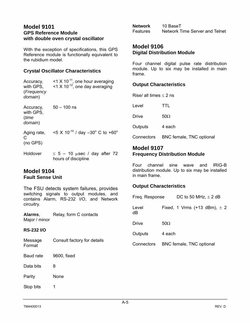
hours of discipline Model 9104 Fault Sense Unit The FSU detects system failures, provides switching signals to output modules, and contains Alarm, RS-232 I/O, and Network circuitry. Alarms, Relay, form C contacts Major / minor RS-232 I/O Message Consult factory for details Format Baud rate 9600, fixed Data bits 8 Parity None Stop bits 1
Network 10 BaseT Features Network Time Server and Telnet Model 9106 Digital Distribution Module Four channel digital pulse rate distribution module. Up to six may be installed in main frame. Output Characteristics Rise/ all times ≤ 2 ns Level TTL Drive 50Ω Outputs 4 each Connectors BNC female, TNC optional Model 9107 Frequency Distribution Module Four channel sine wave and IRIG-B distribution module. Up to six may be installed in main frame. Output Characteristics Freq. Response DC to 50 MHz, ± 2 dB Level Fixed, 1 Vrms (+13 dBm), ± 2 dB Drive 50Ω Outputs 4 each Connectors BNC female, TNC optional

A-6 TM4400013 REV. D
Model 9111 Telecommunications Signal Generator Telecommunications rates and framed signals, T1 or E1 (configured at factory). Rates 1.544 MHz or 2.048 MHz Output TTL, RS-422 & Framed Levels Outputs 4 each Connectors BNC for single ended for TTL.
HDD-15 for RS-422 and Framed Signals
T1 or E1 All “ones” Framing Model 9114 Digital Rate Generator Timing and telecommunications rates Rates Consult factory for rates Level TTL Drive 50Ω Outputs 4 each Connectors BNC female, TNC optional Model 9120 AC Input Power Supply
Operational power for all modules. AC input Universal, 100-240 Vac, 47 to 63 Hz Power output 150 watts, maximum Model 9121 DC Input Power Supply Operational power for all modules. DC input 20-60 VDC input floating with
respect to ground Power output 150 watts, maximum GPS Antenna Gain 35 dB typical Signal filter Triple band-pass Shape Conical Dimensions Maximum diameter, 3.5 inches
Height, 4.0 inches, excluding mast adapter

B-1 TM4400013 REV. D
APPENDIX B
Model 9100 NTS Option

B-2 TM4400013 REV. D
B-1 General The 9100 contains network interface port that resides on the FSU module. This port is primarily used as a Network Time Server (NTS) but also provides a command line interface through Telnet. There are two fielded configurations of the FSU. The old configuration contains a device server from Lantronix and the new configuration contains a TRAK designed network interface. The part numbers of the old FSU configuration with the Lantronix device server is 9104-1 through 9104-8. The part number of new FSU configuration is 9104-9 and above. B-2 Network Port Interface Characteristics The network port characteristics of the two module configurations are tabulated below
Characteristic 9104-1 thru 9104-8 9104-9 and above 10 Base-T √ 10/100 Base-T √ NTP v3 (RFC 1305) √ √ NTP v4 (no RFC) √ SNTP (RFC 2030) √ √ IPv4 √ √ IPv6 √ Telnet √ √ SSH √ Syslog √
B-3 9104-1 through 9104-8 Setup IP Address Setup
Note: While in a Telnet session, time is not available to the network.
The Model 9104 is shipped with a default IP address of 10.1.5.250. To set a different address, the following procedure may be used. To enter or change the IP address, establish a Telnet session utilizing the default address listed above and entering Port 9999. Once the Lantronix (NTS engine manufacturer) serial number and software version message is displayed. (MAC Address and serial number will vary from unit to unit) *** Lantronix NTS *** Serial Number 5021273 MAC address 00:20:4A:50:53:19 Software version 04.52 (011219) Press <Enter> quickly to enter the setup mode. The following messages are displayed: Change Setup : 0 Basic configuration 1 NTS configuration 7 Factory defaults 8 Exit without save 9 Save and exit

B-3 TM4400013 REV. D
Your choice ? <0 Enter > (Basic Configuration) IP address: Enter new IP address Set Gateway IP Address Default (N) <Enter> Netmask: Enter Number of bits (enter 24 for A netmask, 16 for B netmask, or 8 for C netmask). Change Telnet configuration password Default (N) <Enter> To exit and save above entries, <9 Enter > This completes the IP address setup, the Model 9100 is now ready for NTP.
Figure 1, NTS Physical Address Location (FSU) IP Address Set-up, Second Method ARP (Address Resolution Protocol) command is required to change address in this mode. This second method of address setting should only be necessary if the factory default IP address is in use on the network, or a non-valid IP address is loaded into the NTS engine by mistake or the address is not known. To establish a Telnet session to the NTS, an IP address must be associated with the physical hardware. Setting up a new IP address. (Note: This procedure uses 10.1.5.250 as an example IP address and may differ from that which the user is required to input)
1. Refer to Figure 1 for the location of the NTS physical address. This address appears on a label attached to the NTS engine, located on the Model 9104 FSU (Figure 1).
2. From a DOS prompt in the c:\windows directory type:
FSU
XX.XX.XX.XX.XX.XX
NTS Engine
NTS Physical Address

B-4 TM4400013 REV. D
arp –s IP address physical address Example: arp –s 10.1.5.250 00-20-4a-01-7e-9f Where: 10.1.5.250 is the IP address to be temporarily assigned, and the 00-20-4a-01-7e-9f is the physical address (See Figure 1 for location) of the NTS module.
3. From a DOS prompt in the c:\windows directory type
telnet 10.1.5.250 1 Connection will fail – click OK.
4. Click on Connect, Remote System, then enter the following parameters
Host: 10.1.5.250 Port: 9999 Term Type: vt100 Then click “Connect”
The message “*** Lantronix NTS *** Serial Number 5021273 MAC address 00:20:4A:50:53:19 Software version 04.52 (011219). . . is displayed Press <Enter> quickly (within 3 seconds) to enter the setup mode. The following message is displayed: Change Setup : 0 Basic configuration 1 NTS configuration 7 Factory defaults 8 Exit without save 9 Save and exit Your choice ?
5. Basic Configuration –<0 Enter> (Below are the factory settings: user setting may differ)
IP Address : 10 . 1 . 5 . 250 <enter> Set Gateway IP Address (N) Netmask: Number of Bits for Host Part (16) Change telnet config password (N)
6. To exit and save above entries, <9 Enter> This completes setting of the new IP address, the NTS is now ready for operation.
7. The module is ready to resume normal operation. Re-connect the 10BaseT connection to the system and resume normal operation. Have a remote operator ping the new address to verify its remote connection.

B-5 TM4400013 REV. D
B-4 9104-9 and Above Setup The 9104-9 and above is configured through the command line interface using RS-232 I/O port or through the Ethernet port using Telnet or SSH. This module may also be setup by uploading the entire configuration file. To remove a setting, an asterisk * may be entered for an IP address, NETMASK, or GATEWAY. Section B-5 describes the command line interface setup and B-6 describes the configuration file upload.
B-5 Command Line Interface Setup
Command line interface setup can be accomplished through the RS-232 I/O, Telnet (if enabled) or SSH.
Request main configuration setup Host sends: cfg<CR> 9100 replies: ******************************************** * CONFIGURATION SETTINGS * ******************************************** NETWORK SETTINGS ================== IPADDR 10.1.5.250 NETMASK 255.255.252.0 GATEWAY * INETD PROTOCOLS ================ IDLE-TIMEOUT (MINS) ON/OFF DISCONNECT DISABLE ----------- --------------------- ------------- SSH ON 30 -- TELNET OFF 10 0 TFTP OFF -- 0 HTTP OFF -- 0 SYSTEM SETTINGS ---------------------------- RQFS OFF SYSLOG SETTINGS --------------------------- REMOTE * LOG_MASK 7F -> (7) LOG_DEBUG OFF (6) LOG_INFO ON (5) LOG_NOTICE ON (4) LOG_WARNING ON (3) LOG_ERR ON (2) LOG_CRIT ON (1) LOG_ALERT ON (0) LOG_EMERG ON

B-6 TM4400013 REV. D
The main configuration menu for the FSU is displayed above. Below are examples for changing the configuration through the command line. Changing system NETWORK setting Host sends: cfg ipaddr 10.1.233.88<CR> (IP Address set or change) Host sends: cfg netmask 10.1.233.88<CR> (IP Address set or change) Host sends: cfg gateway 10.1.233.88<CR> (IP Address set or change) Enabling or disabling network interfaces such as TELNET or TFTP, Format: cfg <protocol> <on/off> <CR> Where the protocol is SSH, Telnet, TFTP, or HTTP Host sends: cfg telnet on <CR> (to enable) Host sends: cfg telnet off <CR> (to disable) Host sends: cfg tftp on <CR> (to enable) Host sends: cfg tftp off <CR> (to disable) The network interfaces have programmable disconnect and disable timers that expire if a connection is made to the interface but no activity has occurred for the specified timeout period. These timers can also be disabled and each interface is described as follows: SSH port does not have a disable timer but does have a disconnect timer which is the idisconn command. Telnet has both an auto disconnect and auto disable after the timeout elapses. HTTP and TFTP ports can be setup for auto disable upon the expiration of individual programmable timers if no activity has occurred on that port within the set timeout period. Timers with a setting of zero “0” will never time out (Timer disabled). Format: cfg <port> <idisconn/idisable> <timeout setting in minutes><CR> Examples for setting the port-idle disconnect and interface-idle disabling cfg ssh idisconn 30 <CR> (SSH is disconnected after 30 minutes inactivity) cfg telnet idisconn 10<CR> (Telnet is disconnected after 30 minutes inactivity) cfg telnet idisable 20<CR> (Telnet is disabled after 20 minutes of no connection) cfg tftp idisable 5<CR> (TFTP is disabled after 5 minutes of no connection) cfg http idisable 10<CR> (HTTP is disabled after 10 minutes of no connection) System Settings The current status of the RQFS, ReQuest Fault Status message is displayed. (RQFS ON or RQFS OFF) SYSLOG Settings A remote server on the network may be designated to capture SYSLOG events that occur. A log mask of 2 Hex characters converted to binary will denote which of the log events that will be captured in the SYSLOG file. To set the IP address on the remote server, the following format is used: Format: Host sends: cfg syslog remote <IPaddress><CR> The LOG MASK settings are enabled using the following format: cfg log_mask HH<cr> Where: HH is a hex value. The LSB denotes a hex value for a binary representation of the 0 – 3 Log Masks. The MSB denotes the hex value for the binary representation for Log Masks 4 – 7. Host sends: cfg log_mask ff<cr> (to enable all logs)

B-7 TM4400013 REV. D
Factory Default Settings IP address 10.1.5.250 Netmask 255.255.252.0 Gateway * INETD PROTOCOLS ================ IDLE-TIMEOUT (MINS) ON/OFF DISCONNECT DISABLE ----------- --------------------- ------------- SSH ON 30 -- TELNET OFF 10 0 TFTP OFF -- 0 HTTP OFF -- 0 RQFS OFF LOG Masks 00 (all disabled) * denotes not setup ____________________________ Remote login: rifc Password: trak9100
B-6 Upload Configuration File The configuration file can only be uploaded if TFTP is enabled. Below are instructions for loading the configuration file from a Windows platform. 1. Connect to the FSU through the command line using RS-232, Telnet (if enabled), or SSH and type the
following from the 9100 prompt cfgload<CR>
The FSU will respond with the following message:
Platform of remote computer containing configuration file to upload, Windows (W), Unix (U), or Linux (L):
2. For a windows environment, type w<CR>
The FSU will respond with the following information
From a command shell on the remote Windows system, issue the following command to upload configuration file: tftp <IP> put <filename> /var/tftp/config Hit 'Enter' when file upload has completed...
Where: <IP> is the IP address of the unit to be configured <filename> is the path and file to be uploaded
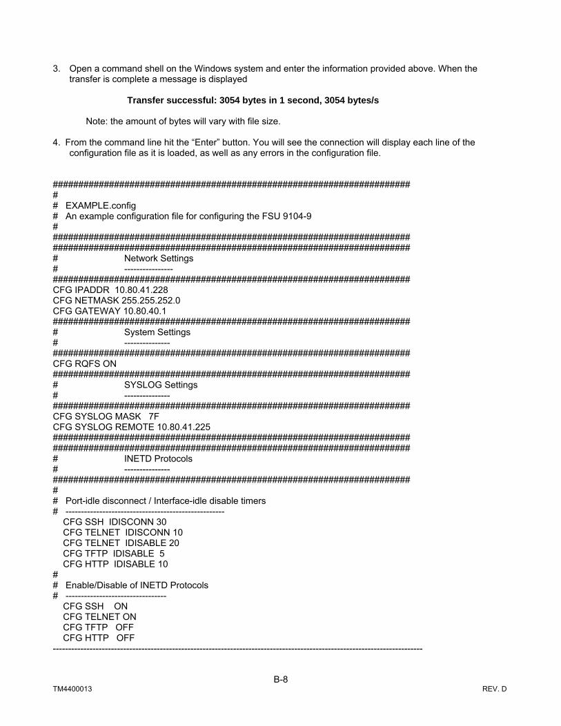
B-8 TM4400013 REV. D
3. Open a command shell on the Windows system and enter the information provided above. When the
transfer is complete a message is displayed
Transfer successful: 3054 bytes in 1 second, 3054 bytes/s Note: the amount of bytes will vary with file size.
4. From the command line hit the “Enter” button. You will see the connection will display each line of the
configuration file as it is loaded, as well as any errors in the configuration file. ###################################################################### # # EXAMPLE.config # An example configuration file for configuring the FSU 9104-9 # ###################################################################### ###################################################################### # Network Settings # ---------------- ###################################################################### CFG IPADDR 10.80.41.228 CFG NETMASK 255.255.252.0 CFG GATEWAY 10.80.40.1 ###################################################################### # System Settings # --------------- ###################################################################### CFG RQFS ON ###################################################################### # SYSLOG Settings # --------------- ###################################################################### CFG SYSLOG MASK 7F CFG SYSLOG REMOTE 10.80.41.225 ###################################################################### ###################################################################### # INETD Protocols # --------------- ###################################################################### # # Port-idle disconnect / Interface-idle disable timers # ---------------------------------------------------- CFG SSH IDISCONN 30 CFG TELNET IDISCONN 10 CFG TELNET IDISABLE 20 CFG TFTP IDISABLE 5 CFG HTTP IDISABLE 10 # # Enable/Disable of INETD Protocols # --------------------------------- CFG SSH ON CFG TELNET ON CFG TFTP OFF CFG HTTP OFF -------------------------------------------------------------------------------------------------------------------------

B-9 TM4400013 REV. D
B-7 Change or Add User/Password Login to the remote interface through the Ethernet port (Telnet or SSH) is password protected. The default username/password is: Username: rifc Password: trak9100 Passwords for existing user accounts can be changed and new user accounts may be added using the PASSWD command: Host Sends: PASSWD<CR>
9100 Replies: 9100 will query for the username, old password (if user already exists), and new password (entered twice).
Examples: 1. Change password for existing user account ‘rifc’ 9100>PASSWD User: rifc Enter old password: trak9100 Enter new password: newpass Re-enter new password: newpass Password for user 'rifc' changed! 9100> 2. Create new user account ‘guest’ 9100>PASSWD User: guest Enter new password: guestpass Re-enter new password: guestpass New user 'guest' added! 9100>

B-10 TM4400013 REV. D
B-8 IP Addresses, Netmask etc An IP address is a 32-bit value, divided into four octets of eight bits each. The standard representation is four decimal numbers (in the range of 0..255), divided by dots. Example: 192.2.1.123 This is called decimal-dot notation. The IP address is divided in two parts: a network and a host part. To support different needs, three “network classes“ have been defined. Depending on the network class, the last one, two or last three bytes define the host, while the remaining part defines the network. In the following text, ‘x’ stands for the host part of the IP address: IP address 1.x.x.x to 127.x.x.x Only 127 different networks of this class exist. These have a very large number of potential connected devices (up to 16777216) Example: 10.0.0.1, (network 10, host 0.0.1) IP address 128.0.x.x to 191.255.xxx.xxx These networks are used for large company networks. Every network can consist of up to 65534 devices. Example: 172.1.3.2 (network 172.1, host 3.2) IP address 192.0.0.xxx to 223.255.255.xxx These network addresses are most common. Most small company networks are class C networks. These networks can consist of a maximum number of 254 hosts. Example: 192.7.1.9 (network 192.7.1, host 9) The remaining addresses 224.x.x.x - 239.x.x.x are defined as “Class D“ and are used as a multicast address. Note: No addresses are allowed with the four highest-order bits set to 1-1-1-1. (240.x.x.x. - 254.x.x.x)These addresses, called "class E", are reserved. The host address with all host bits set to "0" is used to address the network as a whole (for example in routing entries). The address with the host part bits all set to “1“ is the broadcast address, meaning “for every stations“. Network and Broadcast addresses must not be used as a host address (e.g. 192.168.0.0 identifies the entire network, 192.168.0.255 identifies the broadcast address).

B-11 TM4400013 REV. D
The netmask is used to divide the IP address differently from the standard defined by the classes A,B,C. By entering a netmask, it is possible to define how many bits from the IP address are to be taken as the network part and how many bits are to be taken as the host part. Standard IP network netmask
Network bits Host bits Netmask Class A 8 24 255.0.0.0 Class B 16 16 255.255.0.0 Class C 24 8 255.255.255.0
The number of host bits is entered; the Radio Clock then calculates the netmask. The netmask is displayed in standard decimal-dot notation.
Netmask examples
Netmask Host 255.255.255.252 2 255.255.255.248 3 255.255.255.240 4 255.255.255.224 5 255.255.255.192 6 255.255.255.128 7 255.255.255.0 8 255.255.254.0 9 255.255.252.0 10 255.255.248.0 11 . . . . 255.128.0.0 23 255.0.0.0 24
If your network is not connected to the Internet and there are no plans to make such a connection, you may use any IP address you wish.
However, if you are not connected to the Internet and have plans to connect to the Internet or you are connected to the Internet and want to operate your Model 9100 on an Intranet you should use one of the sub-networks below for your network. These network numbers have been reserved for such networks. If you have any questions about IP assignment ask your Network Administrator.
Class A 10.x.x.x Class B 172.16.x.x Class C 192.168.0.x

B-12 TM4400013 REV. D
For more information regarding IP addressing, see the following documents. These can be located, for example, on the World Wide Web using one of the directories or indices:
RFC 950 Internet Standard Subnetting Procedure
RFC 1700 Assigned Numbers
RFC 1117 Internet Numbers
RFC 1597 Address Allocation for Private Internets

TRAK MODEL 9100 MODULAR FREQUENCY/TIME SYSTEM
C-1 TM4400013 REV. D
APPENDIX C
TIME CODE FORMATS

TRAK MODEL 9100 MODULAR FREQUENCY/TIME SYSTEM
C-2 TM4400013 REV. D
APPENDIX C
IRIG B CODE FORMAT
The IRIG B time code has a one-second time frame and contains BCD time information representing seconds, minutes, hours, days and straight-binary-time-of-day (SBTOD) in seconds. Provisions are made in the format for control functions. An 8-millisecond frame reference marker appears during the first 10 ms of each frame, and 8-millisecond position identifiers appear during the 90th millisecond of each 100 millisecond period. The BCD time data appear in the
First five 100 millisecond time periods of each one-second frame, control functions (when used) appear in the next three 100 millisecond time periods, and the SBTOD data appear in the last two 100 ms time periods. Binary ZEROs and fill bits are 2 ms long, and Binary ONEs are 5 ms long. Modifications to the code include deletion of the days data, deletion of the SBTOD data, and deletion of both of these data groups

TRAK MODEL 9100 MODULAR FREQUENCY/TIME SYSTEM
D-1 TM4400013 REV. D
APPENDIX D
Model 9100 DC Power Input Option
Figure D-1. Model 9100DC Front and Rear Panel Views
FREQUENCY OUTPUTS
123456
A A A A A A
BBBBBB
C C C C C C
DDDDDD
AB
GPS ANTENNA
GND
DC INPUT A
DC INPUT B
REFERENCEOUTPUTS
10BASE T
ALARMS
TODRS-232
I/O
LINE20 TO 60 VDC
(6A TO 2A)FUSE: F8AL,250V
F1
J1
A1 A2 A3 A4 A5 A6 A7 A8 A9 A10 A11 A12
E1TB1/F1TB2/F2 J33
J29J30J31 J32
J25J26J27J28
J21J22J23J24
J17J18J19J20
J13J14J15J16
J9J10J11J12
J5J6J7J8 J2 J1
1 2 3
F1
J1
1 2 3
FAULT
TRAKSYSTEMS
INPUT
OUT A
OUT B
OUT C
OUT D
FDM
FAULT
TRAKSYSTEMS
FSU
AUTO
B
A
PRESSTO
RESET
ON LINE
STANDBY
FAULTRESET
SELECT
TRAK Systems
GPS REFERENCE
FAULT
TRAKSYSTEMS
ON LINE
STANDBY
LOCKED
TRACKING
1 PPS
5 MPPS
COMPOSITE
IRIG B
GND
GPS
GPS REFERENCE
FAULT
TRAKSYSTEMS
ON LINE
STANDBY
LOCKED
TRACKING
1 PPS
5 MPPS
COMPOSITE
IRIG B
GND
GPS
OUT A
OUT B
OUT C
OUT D
FAULT
TRAKSYSTEMS
DDM
OUT A
OUT B
OUT C
OUT D
FAULT
TRAKSYSTEMS
DDM
OUT A
OUT B
OUT C
OUT D
FAULT
TRAKSYSTEMS
DDM
OUT A
OUT B
OUT C
OUT D
FAULT
TRAKSYSTEMS
DDM TEL
FAULT
TRAKSYSTEMS
FRAMED
RS-422
TRAKSYSTEMS
FAULT
+5VDC+15VDC
-15VDC
DC/DC P.S.
TRAKSYSTEMS
FAULT
+5VDC+15VDC
-15VDC
DC/DC P.S.

TRAK MODEL 9100 MODULAR FREQUENCY/TIME SYSTEM
D-2 TM4400013 REV. D
D-1. OPTIONAL DC POWER INPUT Appendix D contains only DC power input information. All other information pertaining to the Model 9100 is covered in the main body of this manual. The DC option is factory installed and is specified at time of order. DC versions of the Model 9100 contain a DC model suffix, (9100-8DC) located on the model and serial label on the front, left side of the main frame. D-2 DC INPUT CONNECTIONS DC power input pin connections, for connectors mating with TB1 / TB2, are listed in Table D-1. It is recommended that DC power be applied only after power connections are applied to unit. The DC power supplies accept 20 to 60 VDC. For DC power input to Power Supply A (A11), connect power to DC INPUT A (TB1) and for DC power input to Power Supply B (A12), connect power to DC INPUT B (TB2). The DC Power Supplies are designed to operate over the input range of 20 to 60 VDC and input is floating with respect to chassis / system ground. Therefore, the DC power supplies operate in both +24 volt and –48 volt systems, with only attention to power input connections required. Each DC input is separately fused at the DC input connection. 8 amp fast-blow 5mm X 20mm 250 volt fuses are installed. Replace ONLY with fuse(s) of the same ratings.
Table D-1. DC Power Input Connections, TB1 & TB2
Pin Number Connection For +24 VDC Input For –48 VDC Input
1 Positive DC voltage +24 VDC Input 48 VDC Return 2 Chassis Ground Chassis Ground Chassis Ground 3 Negative DC voltage 24 VDC Return -48 VDC Input
Note: DC power input returns and connecting cable shield should be connected to chassis ground, pin 2.
Table D-2. DC Power Input Interface Cables for EMC Compliance
Reference Designator Mating Connector Interface Cable Type TB1 & TB2 7.62 mm Shielded cable, 14 AWG
minimum size
Table D-3. DC Power Input Rear Panel Connectors and Fuses
Reference Designator
Function Chassis Connector
Mating Connector / Fuse
TB1 20-60 VDC power input to PS A (A11) Phoenix 1804690 Phoenix 1804917 TB1-F1 8 amp, fast blow fuse for PS A (A11) Little Fuse 217 008
TB2 20-60 VDC power input to PS B (A12) Phoenix 1804690 Phoenix 1804917 TB2-F2 8 amp, fast blow fuse for PS B (A12) Little Fuse 217 008

TRAK MODEL 9100 MODULAR FREQUENCY/TIME SYSTEM
D-3 TM4400013 REV. D
D-3 DC POWER SUPPLIES, A11 and A12 The Model 9121 DC/DC Power Supply, shown in Figure D-2, contains a red FAULT indicator and three green power supply output voltage status indicators. The FAULT indicator illuminates if any of the three power supplies voltages fall below a reference level. The appropriate green power supply indicators are normally on and extinguish if a voltage drops below a reference level. The Model 9121 Power Supply is supplied with Model 9100 DC input versions. The DC and AC power supplies have different back plane power connections to avoid damage if the wrong power supply is installed.
Figure D-3. Model 9121 DC Power Supply
D-4. POWER SUPPLY FAILURE If a power supply fails, the FAULT indicator illuminates. To replaced a failed power supply module, proceed as follows: a) Remove DC power from the failed power supply. For example, if the power supply closest to the FSU failed,
remove DC power on the rear panel connector labeled DC INPUT A. b) Before removing a failed DC power supply, check the condition of the fuse located in the fuse holder
associated with the DC power input connector. If the fuse if blown, replace with the same rating as specified in Table D-3.
c) Reconnect DC power to determine if the failed power supply is operational. d) If not, again disconnect DC power and loosen the four front panel screws securing the power supply to the
chassis. e) Holding the power supply module handle, carefully pull on the handle and remove the power supply. f) Install the power supply in the reverse order and reconnect DC power.
TRAKSYSTEMS
FAULT
+5VDC+15VDC
-15VDC
DC/DC P.S.

TRAK MODEL 9100 MODULAR FREQUENCY/TIME SYSTEM
D-4 TM4400013 REV. D
g) Verify the replaced power supply red FAULT indicator is extinguished and the three green status indicators are illuminated.
D-5 REPLACEMENT PARTS LIST
Table D-4. Model 9100DC Power Supply
Model Number Description 9121-1 DC / DC Power Supply

TRAK MODEL 9100 MODULAR FREQUENCY/TIME SYSTEM
TM4400013 REV. D E-2
Appendix E
GPS Antenna, Installation, and Cable Options
Application Note 3.1
April 2004

TRAK MODEL 9100 MODULAR FREQUENCY/TIME SYSTEM
TM4400013 REV. D E-3
GPS Antenna (Typical View)
• Triple Band Pass Filter • LNA, 35 dB Gain • Surge Protect Circuitry • Conical Radome Antenna Types Two antenna types are described, one for 12 volt systems and the other for 5 volt systems. Except for operational voltage, connector types, and mast adapters, both have identical characteristics.
Specifications
Operating Frequency: 1575.42 MHz Filtering: Triple filter, -60 dB @ 1575.42, ±50 MHz Gain: >30 dB, (35 dB typical) Noise Figure 2.2 dB maximum Protection: 80V, IEC1000-4-5 Polarization: Right hand, circular Power supply voltages: 5 volt antenna, +5Vdc, ± 0.5Vdc 12 volt antenna, +4.5Vdc to +15 Vdc Power supply current: 20 ma (typical), 27 ma (maximum), both types Connector types: 5 volt antenna, “N” female 12 volt antenna, “TNC” female Radome color: White Radome shape: Conical Dimensions: Diameter, 3.5 inches and Height, 4.0 inches (excluding mast adapter) Weight: .7 pounds (excluding mast adapter) Temperature: Operational, -40o C to +85o C Storage, -45o C to +90o C
Antenna Installation

TRAK MODEL 9100 MODULAR FREQUENCY/TIME SYSTEM
TM4400013 E-4 REV. D
1-0 General Depending on model, one of two antenna types and a variety of different coaxial cable types and lengths are typically supplied with every TRAK Time and Frequency Systems (TFS) GPS system. Each type antenna requires a different assembly and mounting procedure. The antenna cable type and length depend on the distance between the antenna and the GPS receiver to maintain optimal gain. Before the antenna is assembled and installed, important considerations of personal safety, antenna location, coaxial cable length / type, and lightning protection are required. Suggestions are outlined in the following paragraphs. 1-1 Personal Safety Personal safety is a common sense consideration. Do not attempt to install antenna during rain, lightning, or high winds. Stay clear of power lines and other dangerous objects. 1-2 Antenna Site Selection The antenna should be mounted in a location that has an unobstructed view of the sky. A hemispheric view 5-degree above the horizon is ideal. Roof mounting or mounting on the cable bridge between antenna tower and equipment shelter is usually acceptable. Height is not important, a clear view of the sky is. In northern areas subject to high degrees of snow and ice, do not mount near high structures where falling ice can damage the antenna. Another consideration is to stay as far as possible from other microwave antennas or other sources of RF radiation that could affect reception of the GPS signal and away from lightning rods. 1-3 Coaxial Cable Selection Coaxial cable type and length is very important to maintain the antenna system gain within the limits of the GPS receiver. Therefore, the gain of the antenna, cables, in-line amplifiers, and splitters must be accurately calculated for the system to operate within these limits. Section 2 provides attenuation of different coaxial cables that TRAK provides so end-users can calculate the external gain if cables are altered or not purchased from TRAK. 1-4 Lightning Protection Surge suppressors are not supplied as standard with antennas and coaxial cables. These must be ordered as options. Option L60 is used with the 12 volt antenna (TNC connectors) and Option L60N is used with the 5 volt antenna (N connectors). The surge suppressor should be installed at the point where the coaxial cable enters the building or equipment shelter. It is imperative that the surge suppressor ground lug be connected to a good low impedance earth ground. Some installations require the outer conductor of the coaxial cable also be connected to a low impedance earth ground. Andrew ¼ inch Superflex coaxial cable with an Andrew ground strap (Option L61) is ideal for this requirement.
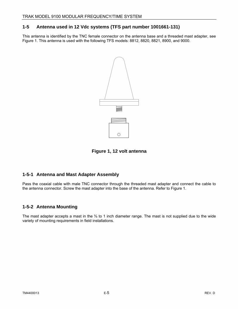
TRAK MODEL 9100 MODULAR FREQUENCY/TIME SYSTEM
TM4400013 E-5 REV. D
1-5 Antenna used in 12 Vdc systems (TFS part number 1001661-131) This antenna is identified by the TNC female connector on the antenna base and a threaded mast adapter, see Figure 1. This antenna is used with the following TFS models: 8812, 8820, 8821, 8900, and 9000.
Figure 1, 12 volt antenna 1-5-1 Antenna and Mast Adapter Assembly Pass the coaxial cable with male TNC connector through the threaded mast adapter and connect the cable to the antenna connector. Screw the mast adapter into the base of the antenna. Refer to Figure 1. 1-5-2 Antenna Mounting The mast adapter accepts a mast in the ¾ to 1 inch diameter range. The mast is not supplied due to the wide variety of mounting requirements in field installations.

TRAK MODEL 9100 MODULAR FREQUENCY/TIME SYSTEM
TM4400013 E-6 REV. D
1-6 Antenna used in 5 Vdc systems (TFS part number 4702337) This antenna is identified by the N female connector on the antenna base and a mast adapter attached to the antenna base with four screws, see Figure 2. This antenna is used with TFS model 9100.
Figure 2, 5 volt antenna 1-6-1 Antenna and Mast Adapter Assembly Pass the coaxial cable with male N connector through the mast adapter and connect the cable to the antenna connector. Attach the mast adapter to the base of the antenna with the four captive screws provided. Refer to Figure 2. 1-6-2 Antenna Mounting The mast adapter accepts a mast in the 1.5 to 1.7 inches diameter range. The mast is not supplied due to the wide variety of mounting requirements in field installations.

TRAK MODEL 9100 MODULAR FREQUENCY/TIME SYSTEM
TM4400013 E-7 REV. D
Coaxial Cable and Accessories Selection 2-0 General 50 feet of RG-58 type coaxial cable is supplied as standard with every GPS model. If a length greater than 50 feet or non-RG-58 cable is required, options are available. A 20 dB line amplifier is available when using long cable runs, consult factory for special applications and considerations. 2-1 Available Antenna Cable Options The common available antenna cable options and accessories are shown in Table 1. If a longer cable is required, consult factory for cable type and GPS line amplifier (if required).
Table 1, Standard Coaxial Cable Options
Antenna Option
Option No.
Description Used On
1001661-131 L9A Antenna & mast adapter, TNC connector, 12VDC Note 1 1001661-209 L10A L9A & 50’ RG-58 Note 1 1001661-210 L11A L9A & 100’ RG-213 Note 1 1001661-221 L22A L9A & 250’ Belden 9913 Note 1 1001661-222 L23A L9A & 2 x 250’ Belden & 20 dB amp Note 1 1001661-227 L28A L9A & 2 x 200’ Belden 9913 & 20 dB amp Note 1 1001661-150 L50 ¼” Andrews TNC- 50’ w/ spare TNC connector Note 1 1001661-151 L51 ¼” Andrews TNC- 100’ w/ spare TNC connector Note 1 1001661-152 L52 ¼” Andrews TNC- 200’ w/ spare TNC connector Note 1 1001661-157 L9N Antenna & mast adapter, “N” connector, 5 VDC Note 2 1001661-158 L70 L9A & L60 & L51 & L61 (100’ cable) Note 1 1001661-159 L71 L9A & L60 & L50 & L61 (50’ Cable) Note 1 1001661-156 L72 L9A & L60 & L52 & L61 (200’ Cable) Note 1 1001661-160 L60 Lightning /surge suppressor (TNC-TNC) Note 1 1001661-161 L61 ¼” Andrews grounding kit Note 1, Note 2 1001661-162 L62 ¼” Andrews cutting tool Note 1, Note 2 1001661-163 L50N ¼” Andrews N- 50’ w/ spare N connector Note 2 1001661-164 L51N ¼” Andrews N- 100’ w/ spare N connector Note 2 1001661-165 L52N ¼” Andrews N- 200’ w/ spare N connector Note 2 1001661-166 L60N Lightning /surge suppressor (N-N) Note 2 1001661-167 L70N L9N & L60N & L51N & L61 (100’ cable) Note 2 1001661-168 L71N L9N & L60N & L50N & L61 (50’ Cable) Note 2 1001661-169 L72N L9N & L60N & L52N & L61 (200’ Cable) Note 2
4700012 ------ 20 dB GPS Line Amplifier, TNC connectors Note 1 Note 1: These assemblies are designed for the 12 volt, TNC connector series which include; 8812, 8820A,
8821, 8900, and 9000.These units Use the L9A antenna, 4.5 to 15 VDC. Standard Antenna Option for these Models unless otherwise specified 1001661-209
Note 2: These assemblies are designed for 5 Volt, “N” connector series, which include the 9100. These units use the L9N antenna option. Standard antenna option for these models unless otherwise specified is 1001661-157 (L9N) & 1001661-163 (L50N)
Note 3: Bold options are complete antenna & cable options.

TRAK MODEL 9100 MODULAR FREQUENCY/TIME SYSTEM
TM4400013 E-8 REV. D
2-1.1 Calculating Antenna System Gain As stated in paragraph 1-3, when selecting the coaxial cable type and length it is very important to maintain the external gain within the limits of the GPS receiver. For the TFS models: 8821, 8900, and 9000 the gain must be greater than 13 dB and less than 23 dB with an optimum gain of approximately 18 in front of the GPS receiver. The TFS Model 9100 gain must be greater than 18 dB but less than 36 dB with an optimum goal of approximately 25 dB in front of the GPS receiver. These values include 3 dB of margin for the minimum and maximum values. Below is an example of how to calculate antenna system gain. Table 2 provides coaxial cable attenuation and delay with the minimum and maximum cables lengths for commonly used cables. Note: TFS 9100 systems sold prior to April 2004 contain a different GPS receiver. The antenna gain for these systems must gain must be greater than 13 dB but less than 30 dB with an optimum goal of approximately 22 dB in front of the GPS receiver.
Antenna System Component Gain (dB) Antenna ∼35 Cable (50’ RG58) -12.45 System connectors and internal cables (typ) - 2 Gain at front end of GPS receiver 20.55
Table 2 Coaxial Cable Delay and Attenuation
Cable Length for 9100 ft (m)
Bold values in MAX & OPTM Column for units sold after April
2004
Cable for Length for 8821, 8900 & 9000 ft
(m)
Coaxial Cable Type
Delay ns/ft (m)
Atten dB/ft (m)
Min Max Optm Min Max Optm
RG-58 1.54 (5.06)
0.249 (0.817)
12 (4)
80 (24)
68 (20)
52 (16)
40 (12)
28 (9)
80 (24)
68 (21)
RG-213 1.54 (5.06)
0.129 (0.423)
23 (7)
155 (47)
150 (39)
100 (31)
77 (23)
54 (17)
155 (47)
132 (40)
9913 Belden
1.21 (3.97)
0.071 (0.233)
42 (13)
281 (85)
239 (72)
183 (56)
140 (42)
99 (30)
281 (85)
239 (73)
FSJ1-50A Andrew
1.21 (3.97)
0.078 (0.256)
38 (12)
256 (78)
217 (66)
166 (51)
128 (39)
90 (27)
256 (78)
218 (66)
FSJ2-50A Andrew
1.23 (3.98)
0.054 (0.177)
55 (17)
370 (112)
314 (95)
241 (73)
185 (56)
130 (113)
370 (112)
315 (96)
LDF4-50A Andrew
1.15 (3.76)
0.031 (0.101)
97 (30)
645 (196)
548 (167)
419 (128)
322 (98)
226 (69)
645 (196)
548 (167)
Note 1: Delay per cable type is specified in nanoseconds (ns) per unit of length at 1575.42 MHz. Factory default setting for the antenna cable delay compensation is 65 ns. This value can be changed through the remote interface or front panel user interface of available. Note 2: The delay should be calculated for each installation and entered into the GPS receiver.

TRAK MODEL 9100 MODULAR FREQUENCY/TIME SYSTEM
TM4400013 E-9 REV. D
Note 3: Attenuation is specified in decibels (dB) per unit length at 1575.42 MHz. NOTE 4: TRAK will not guarantee the performance of the GPS receiver if minimum or maximum cable attenuation is exceeded. 2.2 Attenuator For installations with cable lengths shorter than the minimum cable length in Table 2, an inline attenuator should be used to maintain the external gain within the limits of the GPS receiver. The attenuator must be designed to pass the DC voltage from the receiver to the antenna. This type attenuator is available from GPS Networking Inc. with a specified range of 1 dB to 30 dB attenuation. The attenuation value should be selected to maintain the antenna system near the optimum gain in front of the GPS receiver. The attenuator is not contained in a weather proof housing and therefore must be installed in a protected area.

TRAK MODEL 9100 MODULAR FREQUENCY/TIME SYSTEM
TM4400013 E-10 REV. D
GPS Line Amplifier (Typical Views)
Specifications
Operating Frequency: 1.1 – 1.7 GHz Gain: 20 dB, minimum Noise Figure: < 3.5 dB Input / Output Impedance: 50Ω Reverse Isolation: 35 dB minimum Operating Voltage: 3.6 – 15 Vdc (min-max) Operating Current: < 10 ma (amplifier only) Operating Temperature: -400 C to +750 C
Dimensions: Height: 1.3”
Body length (ex. connectors): 2.5”
Base plate length: 3.25” Width: 2.5”
Weight: 10 oz.
• DC pass through for active antenna • 20 dB Gain
GPS Line Amplifier Installation 3-0 General The GPS Line Amplifier provides necessary gain lost in installations requiring long coaxial cable runs. It’s operational voltage, along with the antenna, is supplied by the GPS receiver. 3-1 Installation The GPS Line Amplifier is not contained in a weather proof housing and therefore must be installed in a protected area. Also, the amplifier must be installed as close to the antenna as permitted by the weather protected area. Consult factory for additional installation information.

TRAK MODEL 9200 MODULAR FREQUENCY/TIME SYSTEM
TM4400013 REV. D
APPENDIX F
Model 9200 Manual

TRAK MODEL 9200 MODULAR FREQUENCY/TIME SYSTEM
TM4400013 REV. D
TECHNICAL MANUAL
MODEL 9200
Modular Frequency/Time System, Digital Distribution Unit
March 2002

TRAK MODEL 9200 MODULAR FREQUENCY/TIME SYSTEM
TM4400013 REV. D
TRAK Systems Model 9200 – Digital Distribution Unit
TRAK MODEL 9200 MODULAR FREQUENCY/TIME SYSTEM
TM4400013 REV. D i
TABLE OF CONTENTS
CHAPTER 1 INTRODUCTION
Paragraph Page 1-1 General 1-1 1-2 Level of Coverage 1-1 1-3 Organization of Manual 1-1 1-4 Functional Description 1-6 1-5 Physical Description 1-6 1-6 Environmental Characteristics 1-6 1-7 Power Requirement 1-6 1-8 EMC/EMI 1-6 1-9 Output Characteristics 1-7
CHAPTER 2 INSTALLATION
2-1 Unpacking Procedure 2-1 2-2 Normal Mounting Procedure 2-1 2-3 Model 9100,9200 Interconnection 2-1 2-4 Rear Panel Connectors 2-2 2-5 Reference Signal Input Connections 2-4 2-6 Distribution Module Switch and Configuration Jumper Settings 2-4
CHAPTER 3 OPERATION
3-1 General 3-1 3-2 Front-Panel Controls and Indicators 3-1 3-3 Model 9106 Digital Distribution Module (DDM) Front Panel 3-2 3-4 Model 9111 Telecommunications Module 3-3 3-5 Model 9250 Terminal & Fault Logic Module (TFL) Front Panel 3-4 3-6 Model 9220 Power Supply Front Panel 3-5 3-7 Operation 3-6
CHAPTER 4
MAINTENANCE 4-1 General 4-1 4-2 Maintenance Philosophy 4-1 4-3 Preventive Maintenance 4-1 4-4 Replacement of Modules 4-1 4-5 Troubleshooting Guide 4-1

TRAK MODEL 9200 MODULAR FREQUENCY/TIME SYSTEM
TM4400013 REV. D ii
LIST OF ILLUSTRATIONS
Figure Page
Model 9200 Digital Distribution Unit 1-1 Model 9200 Module Locations 1-4 1-2 Model 9200 Modular Frequency/Time System Block Diagram 1-5 2-1 Model 9200 Rear Panel 2-2 2-2 Model 9106 Digital Distribution Module (DDM) Switch Locations 2-4 2-3 Model 9111 Telecommunications Module Switch and Jumper Locations 2-5 2-4 Model 9250 Terminal & Fault Logic Module (TFL) Switch Locations 2-6 3-1 Model 9200 Front Panel 3-1 3-2 Model 9250 Terminal & Fault Logic Module (TFL) Front Panel 3-2 3-3 Model 9220-1 Power Supply A5 A6 Front Panel 3-3
LIST OF TABLES
Table Page 1-1 Interface Cables for EMC Compliance 1-5
2-1 Rear Panel Connectors, Fuse, and Switch 2-2 2-3 Reference Inputs 2-3 2-4 DDM Output Signal Switch Positions 2-4 2-5 TEL Framing Format Switch Positions, T1 2-6 3-1 Model 9100 Front Panel Locations 3-1

TRAK MODEL 9200 MODULAR FREQUENCY/TIME SYSTEM
TM4400013 REV. D 1-1
CHAPTER 1
INTRODUCTION
1-1 GENERAL This manual contains the description, installation, operation, and maintenance instructions for the Model 9200 Digital Distribution Unit (DDU). It is intended to provide electronics personnel with the information necessary to operate and to maintain it to the lowest replaceable unit, LRU, or assembly level.
1-2 LEVEL of COVERAGE This manual provides coverage to the LRU only. No schematic or logic diagrams of replaceable assemblies are provided. Unlike instruments in use a few decades ago, where it was possible to troubleshoot to the logic gate level, the Model 9200 uses modern technology consisting of CPU’s, gate arrays, and imbedded software. Packaging is largely surface-mount technology. Only factory-trained technicians with a high level of training can perform maintenance below the LRU level. Most LRU’s have an MTBF in excess of ten years, so frequent replacements are usually not required.
1-3 ORGANIZATION of MANUAL The body of this manual describes operation of the basic Model 9200 and its most common plug-in modules.
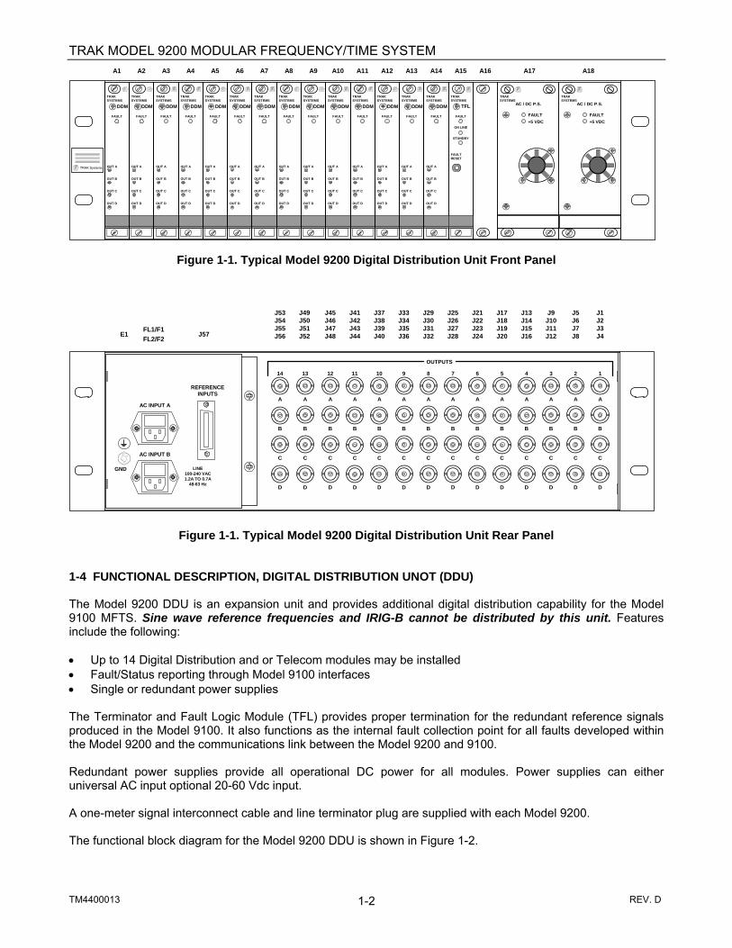
TRAK MODEL 9200 MODULAR FREQUENCY/TIME SYSTEM
TM4400013 REV. D 1-2
Figure 1-1. Typical Model 9200 Digital Distribution Unit Front Panel
Figure 1-1. Typical Model 9200 Digital Distribution Unit Rear Panel
1-4 FUNCTIONAL DESCRIPTION, DIGITAL DISTRIBUTION UNOT (DDU) The Model 9200 DDU is an expansion unit and provides additional digital distribution capability for the Model 9100 MFTS. Sine wave reference frequencies and IRIG-B cannot be distributed by this unit. Features include the following: • Up to 14 Digital Distribution and or Telecom modules may be installed • Fault/Status reporting through Model 9100 interfaces • Single or redundant power supplies The Terminator and Fault Logic Module (TFL) provides proper termination for the redundant reference signals produced in the Model 9100. It also functions as the internal fault collection point for all faults developed within the Model 9200 and the communications link between the Model 9200 and 9100. Redundant power supplies provide all operational DC power for all modules. Power supplies can either universal AC input optional 20-60 Vdc input. A one-meter signal interconnect cable and line terminator plug are supplied with each Model 9200. The functional block diagram for the Model 9200 DDU is shown in Figure 1-2.
E1FL1/F1FL2/F2
J57
J21J22J23J24
J17J18J19J20
J13J14J15J16
J9J10J11J12
J5J6J7J8
J1J2J3J4
OUTPUTS
67891011
A A A A A A
BBBBBB
C C C C C C
DDDDDD
GND
AC INPUT A
AC INPUT B
REFERENCEINPUTS
LINE100-240 VAC1.2A TO 0.7A
48-63 Hz
12345
A A A A A
BBBBB
C C C C C
DDDDD
121314
A A A
BBB
C C C
DDD
J45J46J47J48
J41J42J43J44
J37J38J39J40
J33J34J35J36
J29J30J31J32
J25J26J27J28
J53J54J55J56
J49J50J51J52
TRAK Systems OUT A
OUT B
OUT C
OUT D
FAULT
TRAKSYSTEMS
DDM
OUT A
OUT B
OUT C
OUT D
FAULT
TRAKSYSTEMS
DDM
OUT A
OUT B
OUT C
OUT D
FAULT
TRAKSYSTEMS
DDM
OUT A
OUT B
OUT C
OUT D
FAULT
TRAKSYSTEMS
DDM
OUT A
OUT B
OUT C
OUT D
FAULT
TRAKSYSTEMS
DDM
OUT A
OUT B
OUT C
OUT D
FAULT
TRAKSYSTEMS
DDM
OUT A
OUT B
OUT C
OUT D
FAULT
TRAKSYSTEMS
DDM
OUT A
OUT B
OUT C
OUT D
FAULT
TRAKSYSTEMS
DDM
OUT A
OUT B
OUT C
OUT D
FAULT
TRAKSYSTEMS
DDM
OUT A
OUT B
OUT C
OUT D
FAULT
TRAKSYSTEMS
DDM
OUT A
OUT B
OUT C
OUT D
FAULT
TRAKSYSTEMS
DDM
OUT A
OUT B
OUT C
OUT D
FAULT
TRAKSYSTEMS
DDM
OUT A
OUT B
OUT C
OUT D
FAULT
TRAKSYSTEMS
DDM
OUT A
OUT B
OUT C
OUT D
FAULT
TRAKSYSTEMS
DDMFAULT+5 VDC
AC / DC P.S.
TRAKSYSTEMS
A1 A2 A3 A4 A5 A6 A7 A8 A9 A10 A11 A12 A13 A14 A15 A16 A17 A18
FAULT
TRAKSYSTEMS
TFL
ON LINE
STANDBY
FAULTRESET
FAULT+5 VDC
AC / DC P.S.
TRAKSYSTEMS

TRAK MODEL 9200 MODULAR FREQUENCY/TIME SYSTEM
TM4400013 REV. D 1-3
Figure 1-2.
DC to allmodules
"B" Refs.
A/B Switch
"A" Refs.
Model 9200Block
Diagram
P.S. Status
"A" References
"B" References
Status
A/B Switch
(SignalsTo/From
9100)
Terminatorand
Fault Logic
Model9250
DDM or TEL,1 of 14,
Model 9106 or9111
DDM or TEL,14 of 14,
Model 9106 or9111
Power Supply "A"Model 9220
Power Supply "B"Model 9220
Status
1 PPS,5 MPPS,or
Composite Out(Selected in DDM)or T1 or E1 from
TEL
1 PPS,5 MPPS,or
Composite Out(Selected in DDM)or T1 or E1 from
TEL
PowerInput
A
PowerInput
B

TRAK MODEL 9200 MODULAR FREQUENCY/TIME SYSTEM
TM4400013 REV. D 1-4
1-5 PHYSICAL DESCRIPTION The Model 9200 DDU is a single chassis designed for mounting in a standard EIA, 19 inch wide equipment rack. Front panel height is 5.22 inches (3U) and overall depth is 15.0 inches exclusive of front panel handles and rear panel connectors. Weight is approximately 25 pounds with all modules installed. All functional modules plug-in through the front of the unit. System controls, status indicators, and test points are located on module front panels. There are 18 front panel plug-in module locations, A1- A14 are available for Digital Distribution modules (DDM) and / or Telecommunications modules (TEL). A15 and A16 are reserved for Terminator and Fault Logic modules (TFL). Typically only one TFL module is installed in location A15. A17 and A18 are reserved for Power Supply modules. Weight is approximately 25 pounds with all modules installed. System status indicators and test points are located on module front panels. All connections to the unit are via rear panel connectors with exception of the Telecom module, which contains two front panel high-density 15-pin DD-sub connectors for Framed and EIA-RS-422 output signals. 1-6 ENVIRONMENTAL CHARACTERISTICS Unless otherwise specified, Model 9200 meets all published specifications when operated over the temperature range of –30°C to +60°C with a rate of change <2°C/minute. Maximum operating humidity is 95%, non-condensing. The unit withstands normal shock and vibration found in all forms of common-carrier shipment. 1-7 POWER REQUIREMENTS The Model 9200 operates from 100 to 240 VAC ± 10%, 48-63 Hz single-phase power. Power consumption with all modules installed is approximately 80 watts. As an option, the system can be ordered with DC power supply in place of the AC power supply. Input voltage is 20-60 VDC. Refer to Appendix D for further details. 1-8 EMC/EMI The Model 9200, when used with the Model 9100, meets the requirements of FCC Part 15 Class B for North America and Product Family harmonized standards EN55022 and EN55024 for emissions and immunity compliance of the EMC Directive 89/335/EEC and its amendments. Note: In order to comply with the standards above, the following interface cables or equivalent listed in Table 1-1 must be used.
Table 1-1 Interface Cables for EMC Compliance
Reference Designator Connector Interface cable type
J1 through J56 BNC RG-400
Telecom Module J1 & J2 HD 15-pin D-SUB Shielded twisted pair
J57 24 pin TRAK supplied cable
FL1 & FL2 IEC-320 TRAK supplied power cords
TRAK MODEL 9200 MODULAR FREQUENCY/TIME SYSTEM
TM4400013 REV. D 1-5
1-9 OUTPUT CHARACTERISTICS The Model 9200 output signal characteristics are identical to the digital output characteristics of the Model 9100 modules. Refer to the Model 9100 technical manual section 1-9 for output characteristics of the DDM and TEL modules. 1-10 ALARMS Refer to Model 9100 manual section paragraph 1-11 for complete descriptions.

TRAK 9200 MODULAR FREQUENCY/TIME SYSTEM
TM4400013 REV. D 2-1
CHAPTER 2
INSTALLATION
2-1 UNPACKING PROCEDURE The Model 9200 is packed for shipment in molded foam end-caps. Accessories, such as manual, cables, power cords, and mating connectors are contained in the same box as the Model 9200. Unpack the system as follows:
a. Examine shipping container for any signs of damage and rough handling. Record any damage
observed and report to carrier. b. Remove and retain shipping list from outside of carton. c. Open shipping carton top and lift out the Model 9200 system. d. Examine contents for any sign of damage and record any damage noted. e. Remove accessories from the carton. f. Check to ensure that all items listed on the packing list have been removed from the shipping
carton. g. Retain shipping carton and packing material for future use.
2-2 SYSTEM MOUNTING PROCEDURE The Model 9200 is designed for mounting in an EIA standard 19-inch rack. Unit height is 5.22 inches and the depth is 15.00 inches. Allow at least four inches behind the unit for cable clearance. Free flow of circulating air should be available to assure an ambient temperature does not exceed +60oC. Typically the Model 9200 is located above or below the Model 9100.
2-3 MODEL 9100/9200 INTERCONNECTION An interconnect cable and terminator plug are supplied with every Model 9200. Connect the Models 9100 and 9200 together. After connecting, place the terminator plug at the Model 9200 end. If more than one Model 9200 is used, terminate the last Model 9200 input.

TRAK 9200 MODULAR FREQUENCY/TIME SYSTEM
TM4400013 REV. D 2-2
2-4 REAR PANEL CONNECTORS AND FUSES The Model 9200 rear panel is shown in Figure 2-1. All connectors, fuses, and indicators are described in Table 2-1.
Figure 2-1. Model 9200 Rear Panel
Table 2-1. Rear Panel Connectors and Fuses
REF DES FUNCTION
CHASSIS CONNECTOR
MATING CONNECTOR
J57 Reference Inputs from Model 9100 (See Table 2-3 for connections)
AMP 554088-1 female
Interface cable, 1meter, supplied by TRAK
J1 – J56 DDM Installed, 1PPS, 5 MPPS, or Comp. BNC Female BNC Male
J1 – J56 TEL Installed, TTL level clock, T1 or E1 BNC Female BNC Male
FL1 100 to 240 Vac, power to PS A (A17) IEC-320 type Power Cord
F1 3 amp slo-blo fuse for PS A (A17) Installed in FL1
FL2 100 to 240 Vac power to PSB ( A18) IEC-320 type Power Cord
F2 3 amp slo-blo fuse for PSB (A18) Installed in FL2
E1FL1/F1FL2/F2
J57
J21J22J23J24
J17J18J19J20
J13J14J15J16
J9J10J11J12
J5J6J7J8
J1J2J3J4
OUTPUTS
67891011
A A A A A A
BBBBBB
C C C C C C
DDDDDD
GND
AC INPUT A
AC INPUT B
REFERENCEINPUTS
LINE100-240 VAC1.2A TO 0.7A
48-63 Hz
12345
A A A A A
BBBBB
C C C C C
DDDDD
121314
A A A
BBB
C C C
DDD
J45J46J47J48
J41J42J43J44
J37J38J39J40
J33J34J35J36
J29J30J31J32
J25J26J27J28
J53J54J55J56
J49J50J51J52

TRAK 9200 MODULAR FREQUENCY/TIME SYSTEM
TM4400013 REV. D 2-3
2-5 REFERENCE SIGNAL INPUT CONNECTIONS The pin connections for the Frame Reference Inputs, J57, are listed in Table 2-3.
Table 2-3, Reference Inputs, J57
Pin No
FUNCTION
Pin No
FUNCTION
1 RS-232 B 13 Ground
2 RS-232 A 14 Ground
3 1 PPS B 15 Ground
4 1 PPS A 16 Ground
5 5 MPPS B 17 Ground
6 5 MPPS A 18 Ground
7 Composite B 19 Ground
8 Composite A 20 Ground
9 GPS Status A 21 GPS Status B
10 I2C Interface Data 22 Ground
11 I2C Interface Clock 23 Ground
12 Not Used 24 Ground

TRAK 9200 MODULAR FREQUENCY/TIME SYSTEM
TM4400013 REV. D 2-4
2-6 DISTRIBUTION MODULE SWITCH and CONFIGURATION JUMPER SETTINGS The Model 9200 accepts both the Model 9106 DDM and the 9111 TEL modules. Either module types may be installed in any position, A1 – A14. Refer to the Model 9100 technical manual section 2-8 for DDM and TEL module configurations. 2-6-1 TERMINATOR and FAULT LOGIC (TFL), (A15, A16) The Model 9250 TFL is installed in position A15. The TFL/DDU address switch, S2, must be set so that the Model 9100, FSU “knows” the address of the DDU. Set S2 for 0 for a single DDU, 1 for two DDU’s, etc. Note: Actual TFL address is not important as insuring that no two Model 9200, that are connected to the same Model 9100, have the same address.
Figure 2-2. TFL Switch Location
S2
Address
TFL

TRAK MODEL 9200 MODULAR FREQUENCY/TIME SYSTEM
3-1 TM4400013 REV. D
CHAPTER 3
OPERATION
3-1 GENERAL This chapter covers the operation of the Model 9200 including a description of front and rear panel controls and indicators, initial synchronization and fault detection. 3-2 FRONT PANEL CONTROLS AND INDICATORS The Model 9200 front panel is shown in Figure 3-1. Table 3-1 lists each module with its system reference designator and gives a description of the Module. A view of each module front panel along with a description of controls and indicators is also provided. Further details for each module are given in Appendix G.
Figure 3-1. Model 9200 Front Panel
Table 3-1. Model 9200 Front-Panel Module Locations and Functions
REF DES
DESCRIPTION
A1- A14
DDM and/or TEL modules may be installed in these locations.
A15, TFL module position. A17, A18
Power Supply module. Provides Diode “OR’ed” +5, +15, and -15 Vdc to all modules. Two modules are used for dual redundancy. May be AC or optional 20-60 Vdc input power supplies.
TRAK Systems OUT A
OUT B
OUT C
OUT D
FAULT
TRAKSYSTEMS
DDM
OUT A
OUT B
OUT C
OUT D
FAULT
TRAKSYSTEMS
DDM
OUT A
OUT B
OUT C
OUT D
FAULT
TRAKSYSTEMS
DDM
OUT A
OUT B
OUT C
OUT D
FAULT
TRAKSYSTEMS
DDM
OUT A
OUT B
OUT C
OUT D
FAULT
TRAKSYSTEMS
DDM
OUT A
OUT B
OUT C
OUT D
FAULT
TRAKSYSTEMS
DDM
OUT A
OUT B
OUT C
OUT D
FAULT
TRAKSYSTEMS
DDM
OUT A
OUT B
OUT C
OUT D
FAULT
TRAKSYSTEMS
DDM
OUT A
OUT B
OUT C
OUT D
FAULT
TRAKSYSTEMS
DDM
OUT A
OUT B
OUT C
OUT D
FAULT
TRAKSYSTEMS
DDM
OUT A
OUT B
OUT C
OUT D
FAULT
TRAKSYSTEMS
DDM
OUT A
OUT B
OUT C
OUT D
FAULT
TRAKSYSTEMS
DDM
OUT A
OUT B
OUT C
OUT D
FAULT
TRAKSYSTEMS
DDM
OUT A
OUT B
OUT C
OUT D
FAULT
TRAKSYSTEMS
DDMFAULT+5 VDC
AC / DC P.S.
TRAKSYSTEMS
A1 A2 A3 A4 A5 A6 A7 A8 A9 A10 A11 A12 A13 A14 A15 A16 A17 A18
FAULT
TRAKSYSTEMS
TFL
ON LINE
STANDBY
FAULTRESET
FAULT+5 VDC
AC / DC P.S.
TRAKSYSTEMS

TRAK MODEL 9200 MODULAR FREQUENCY/TIME SYSTEM
3-2 TM4400013 REV. D
3-3 DIGITAL DISTRIBUTION MODULES Refer to the Model 9100 technical manual section 3-2 for DDM and TEL module configurations. The TEL is described in the following paragraph. 3-3-1 TERMINATOR and FAULT LOGIC, A15 The Model 9250 Terminator and Fault Logic front panel shown in Figure 3-4 contains the following LED indicators:
FAULT red, module fault summation ON LINE green, indicates module is on line
STANDBY green, indicated module is in standby (not used)
The Model 9250-1 Terminator and Fault Logic front panel shown in Figure 3-4 contains the following switches: FAULT RESET Pressing FAULT RESET clears any latched faults in the DDU(s).
Figure 3-2. Model 9250 Terminator and Fault Logic (TFL) A15
FAULT
TRAKSYSTEMS
TFL
ON LINE
STANDBY
FAULTRESET

TRAK MODEL 9200 MODULAR FREQUENCY/TIME SYSTEM
3-3 TM4400013 REV. D
3-6 POWER SUPPLIES, A17 and A18 The Model 9220 Power Supply front panel shown in Figure 3-5 contains the following LED indicators:
FAULT red, power supply fault summation + 5 Vdc green, indicates + 5 Vdc power supply good
Figure 3-3. Model 9220 Power Supply (A17 and A18)
FAULT+5 VDC
AC / DC P.S.
TRAKSYSTEMS

TRAK MODEL 9200 MODULAR FREQUENCY/TIME SYSTEM
3-4 TM4400013 REV. D
3-7 OPERATION With the Model 9200 connected to the Model 9100 and DDM and/or TEL modules are installed, the DDU is operational.
Apply power to the system and observe that all the green power supply indicators are illuminated.
NOTE:
TFL modules take approximately 5 seconds to initialize and all TFL indicators are on at this time.
Pressing FAULT RESET on TFL module should clear all FAULT indicators. The DDU is now operational.

TRAK MODEL 9200 MODULAR FREQUENCY/TIME SYSTEM
4-1 TM4400013 REV. D
CHAPTER 4
MAINTENANCE
4-1 GENERAL The Model 9200 provides maintenance-free operation for the life of the system. This chapter contains instructions for locating and correcting failures in the Model 9200. Troubleshooting instructions are provided for locating and replacing modules. No troubleshooting aids are provided beyond the module level. 4-2 MAINTENANCE PHILOSOPHY All the circuits in the MFTS are in front panel replaceable modules, allowing rapid repair at the system operational level. Additionally, all modules contain fault indicators, allowing rapid recognition and replacement of a failed module. No attempt should be made to repair a module. These assemblies should be returned to the factory for repair. 4-3 PREVENTIVE MAINTENANCE Preventive maintenance of the system consists mainly of cleaning and general inspection to maintain the best environment for the equipment operation. 4-4 REPLACEMENT OF MODULES As noted above, hot replacement of power supply modules should be limited to those times when continued system operation is required during normal deployment. A procedure for Power Supply replacement is provided in Paragraph 4-5.3. 4-5 TROUBLESHOOTING GUIDE The following paragraphs provide corrective actions for system failures. Included are procedures for fault recognition, failed module location, and for module replacement.

TRAK MODEL 9200 MODULAR FREQUENCY/TIME SYSTEM
4-2 TM4400013 REV. D
4-5.1 Distribution Failures The Model 9200 contains up to 14 Distribution Modules. If any of the modules fail, the appropriate FAULT indicator on the failed Distribution Module illuminates. Test points are provided to verify reference signals are present. Before replacing a failed module, remove all coaxial signal output cables, on the rear panel, associated with the failed module and depress the TFL “FAULT RESET” switch (on the 9200). If the “FAULT” indicator of the module is cleared, the problem may be a shorted cable or a failure at the receiving end of the cable. For proper operation of the distribution fault sense circuits, cable ends must be terminated into 50Ω. If the failure persists replace the failed module as follows: a. Loosen the two screws securing the failed module to the chassis.
b. Holding the handle of the module, carefully pull on the handle and withdraw module.
c. Install the new Distribution module and secure to chassis by tightening the two front panel screws.
d. At the TFL front panel, depress the FAULT RESET switch and assure that the FAULT indicator is extinguished.
4-5.2 Terminator and Fault Logic (TFL) Module Failures If the FAULT indicator on the TFL module illuminates and/or there is a loss of external communications, replace the TFL module. a. Loosen the two screws securing the failed module to the chassis.
b. Holding the handle of the module, carefully pull on the handle and withdraw module. c. Install the new module and secure to chassis by tightening the two front panel screws. d. Depress the TFL FAULT RESET switch and assure that the FAULT indicator is extinguished.
4-5.3 Power Supply Failure If a Power Supply Module fails, the fault indicator of the failed module illuminates and one or more of the power present indicators will be out. To replace a failed Power Supply Module proceed as follows: a. Remove AC power to the failed power supply. For example if the Power Supply module closest
to the FSU failed, remove power cord on rear panel labeled AC or DC INPUT A. If Power Supply module closest to the edge of the chassis failed, remove power cord on rear panel labeled AC or DC INPUT B.
b. Before removing a failed Power Supply module, check to see if the fuse located on the filter
fuse assembly supplying AC power to the Power Supply Module is good. If the fuse is blown, replace fuse with the spare fuse in the fuse compartment of the filter/fuse assembly. Remember to replace spare fuse in filter/fuse assembly.
c. Reconnect AC power cord or DC and verify that the power supply is operating. d. If power supply is still not working, disconnect AC power cord or DC and loosen the four front
panel screws securing the Power Supply to the chassis.

TRAK MODEL 9200 MODULAR FREQUENCY/TIME SYSTEM
4-3 TM4400013 REV. D
e. Holding the Power Supply handle towards the left of the module, carefully pull on handle and remove module.
f. Install a new power supply and secure to chassis by tightening the four front panel screws.
Reconnect AC power cord or DC. g. Verify that the “FAULT” indicator of the power supply is extinguished and all the green power
supply indicators are illuminated.

TRAK MODEL 9200 MODULAR FREQUENCY/TIME SYSTEM
5-1 TM4400013 REV. D
CHAPTER 5
REPLACEABLE PARTS LIST
5-1 GENERAL Table 5-1 lists replaceable modules in the Model 9200. If ordering a module from the factory, either the module part number or model number may be used.
TABLE 5-1 REPLACEMENT PARTS LIST
Ref. Des. Description Model number
Qty.
A1-14 Digital Distribution Module (DDM) 9106-1 1-14*
A1-14 Telecom Signal Generator Module, T1 9111-1 1-14*
A1-14 Telecom Signal Generator Module, E1 9111-2 1-14*
A15 Terminator and Fault Logic Module 9250-1 1
A16 Blank Panel
A11 and A12
AC/DC Power Supply (for AC input) 9220-1 2
A11 and A12
DC/DC Power Supply (for 20-60 Vdc input) 9221-1 2
NOTE: * Number and location of modules varies from site to site.

TRAK MODEL 9100 MODULAR FREQUENCY/TIME SYSTEM
G-1 TM4400013 REV. D
APPENDIX G
Model 9100 Module Data Sheets
To Be Supplied

TRAK MODEL 9100 MODULAR FREQUENCY/TIME SYSTEM
H-1 TM4400013 REV. D
APPENDIX H
CE Compliance Certificate

TRAK MODEL 9100 MODULAR FREQUENCY/TIME SYSTEM
H-2 TM4400013 REV. D
European Contact: TRAK Microwave Limited Dunsinane Avenue Dundee, Scotland DD2 3QF Phone: 1382 833411 Contact: Graham Bodie