model 344 shortfinder plus instruction manual revised 11
TRANSCRIPT

Model 344 Shortfinder Plus Instruction Manual Revised 11-24-12 Page#1
S & C Distribution Company
7225 Duvan Drive
Tinley Park, IL

Model 344 Shortfinder Plus Instruction Manual Revised 11-24-12 Page#2
TABLE OF CONTENTS
Chapter Description Page Number
1. Introduction………………………………………………………………… 3
Warranty………………………………………………………………… 4
2. Specifications………………………………………………………………. 5
3. How it works………………………………………………………………... 8
4. Application Procedures
A. General…………………………………………………………... 15
B. Safety…………………………………………………………….. 16
C. Shortfinder Calibration………………………………………….. 16
D. Checking Track Circuits………………………………………... 17
E. Checking Line or Cable Circuits………………………………. 26
F. Other Considerations & Uses………………………………….. 29
G. Evaluating Testing shunts……………………………………… 32
5. Guidline For Locating Shorted or Open Track Circuits
A. General…………………………………………………………... 34
B. Safety…………………………………………………………….. 34
C. At the Battery End of a Track Circuit…………………………. 35
D. At the Relay End of a Track Circuit…………………………… 36
E. At an intermediate Point in A Track Circuit………………….. 37
6. Accessories………………………………………………………………… 38
7. Trouble Shooting Guide………………………………………………….. 40

Model 344 Shortfinder Plus Instruction Manual Revised 11-24-12 Page#3
Chapter 1
INTRODUCTION
In response to a request from a Class I Railroad, S & C Distribution Company developed the Model
324 Shortfinder in 1991. Because of changes in technology, and to improve the product, the Model 344
was designed to replace the 324 in 2012.
Due to the electrical complexity of track configurations the presence of a short is easily determined,
but, without a tool such as a Shortfinder, it can take long hours of trial and error work before the actual
shorted component is identified. In the hands of expert or novice, the Model 344 can reduce trouble
shooting time substantially. Please note that while designed for use on the track, the Shortfinder can also
be used for locating shorts and grounds in line and cable circuits.
As a Shortfinder, the unit provides two user selectable frequencies (3 KHz and 24 KHz) to feed, via
probe equipped leads, into the suspect area. Use the low frequency (3 KHz) to reach out on long track or
line and cable circuits. Use the high frequency (24 KHz) for work in turnouts, interlocking plants, and when
you get close to the short on a long track or wire circuit. The Voltage that is generated within the
Shortfinder is registered on the OLED Display of the Shortfinder. The reading is in the form of: a bar graph,
the traditional Shortfinder numbering system (0-15) and in Ohms. The higher the reading (or lower the
ohms) the closer one is to the short. A full scale reading on the Shortfinder indicates you are at a zero ohm
short. Readings can be taken across an insulated joint end post, rail-to-rail across the track, bolt to rail,
across gauge and switch rod insulation, etc.
To further assist the diagnosis of track circuit problems, the Model 344 Shortfinder is also equipped
with a voltage display, which in "Voltage" mode will display up to 17 Volts of DC and 17 Volts of AC. A
push of the “B” button will also display a spectrum of the frequencies on the track. This function allows the
user to determine if the false track occupancy indication (track circuit failure) is due to a short or an open, or
other conditions of interference. Opens in a track circuit can also be found by taking track voltage readings
with the Shortfinder in voltmeter mode.
A newer application of the Shortfinder is to verify the resistance values of testing shunts. Because
the Shortfinder can measure ohms it can be used to test testing shunts for conformance to the required
values before initiating cutovers, ahead of a visit by an FRA inspector, etc. Other applications include
taking ballast resistance measurements and looking for high resistance bonds, track wire connections, etc.
A padded, zippered nylon carrying case is furnished along with a pair of probe-equipped test leads
and a battery charger for the internal 12V Gel Cell Battery. Accessories available include a 12VDC to
12VDC In Vehicle Charging Adapter (PN: 324-12) , Shoulder Harness for the Carrying Case (PN: 324-20),
a set of Quick Read Probe Tips (PN: 324-18), a Rail Clamp Connector Set (PN: 324-31), All accessories ae
discussed in Chapter VII of this manual.

Model 344 Shortfinder Plus Instruction Manual Revised 11-24-12 Page#4
Chapter 1, Continued
LIMITED AND EXCLUSIVE WARRANTY
THIS LIMITED AND EXCLUSIVE WARRANTY IS GIVEN TO THE PURCHASER BY S & C
DISTRIBUTION COMPANY AND IS THE SOLE AND EXCLUSIVE WARRANTY GIVEN IN
CONNECTION WITH THE MODEL 344 SHORTFINDER. ALL OTHER WARRANTIES, EITHER
EXPRESS OR IMPLIED ARE EXCUDED TO THE FULL EXTENT PROVIDED BY LAW.
S&C Distribution Company hereby warrants the Model 344 Shortfinder, exclusive of batteries, to be
free from defects in material and workmanship for a period of one year following the date of shipment. Any
manufacturing defects arising during this warranty period shall be corrected at the Manufacturers expense
(except inbound shipping and handling charges).
1. To obtain warranty services, a claim by the purchaser in writing must be made to S&C Distribution
Company at the address shown on the front of this Instruction Manual. Such claim must be
accompanied by the S & C Distribution Company sales order number, or other proof of purchase.
2. This Limited and Exclusive Warranty only covers repairs of Manufacture’s defects and requires that
in-bound freight charges be prepaid.
3. S & C Distribution Company shall not be responsible for any injury to persons or damage to
property or any of it’s contents or for any other consequential damages or losses whether arising
out of breech of contract, breach of warranty, or otherwise. Some states do not allow this
exclusion or limitation of incidental or consequential damage so this limitation or exclusion may not
apply to you.
4. This Limited and Exclusive Warranty may give you specific legal rights according to the law of your
state.
5. The Warranty contained in this Agreement shall not apply to any Model 344 Shortfinder which shall
have been repaired or altered outside of the Manufacturer’s facilities or tampered with in any way,
or in the Manufacturer’s sole judgment has been subject to misuse, negligence or accident not
attributable to the Manufacturer.
6. This Warranty is issued to the original purchaser only and is not transferable.
7. This Warranty replaces and supersedes any and all previous issued warranties.

Model 344 Shortfinder Plus Instruction Manual Revised 11-24-12 Page#5
CHAPTER 2
Specifications
1. Frequencies: User Selectable: 3KHz and 24KHz.
2. Shortfinder Range: 3KHz Track 1,200 to 1,500 Ft.
Line or Cable approx. 1 mile
24Khz Track 300 to 400 Ft.
Line or Cable approx. 1000 Ft.
3. Output Level: Less than -5 db depending on load (track impedance)
4. Output/Input Impedance: 4 Ohms at 3KHz and 24 KHz.
5. DC Blocking: Output: 250VDC Capacitor Coupled
Input: High Impedance. (>20,000 Ω)
6. Circuit Voltage: Will withstand application of 117VAC on any input.
7. Short Indicator: OLED Bar Graph, 0-15 Measurement, and Ohms.
8. Voltmeter: Measures 0-17 VDC
Measures 0-17 VAC
Displays Spectrum
9. Meter Impedance: > 20,000Ω
10. Spectrum Width 0 to 20KHz
11. Accuracy Voltage and Ohms +/- 3%
Frequency Measurements +/- 1Hz
12. Internal Battery: 12V 1.2AH Lead Acid Gel Cell.
13. Low Battery Indicator: Battery Voltage displayed on Screen,
Displays “Low Battery” when voltage is below 11.5V
Turns off most functions and displays “Turn Unit Off and
Recharge” at 10V if the temperature is above 20°F and at 11.2V when the temperature is below 20°F.
14. Battery Life: Normal day’s use.
15. Clock Battery: 6 Years.
Model 344 Shortfinder Plus Instruction Manual Revised 11-24-12 Page#6
CHAPTER 2, Continued
Specifications Continued
16. Physical:
Dimensions 9” L X 5 3/8”W X 4 1/8”H (Including Terminals.)
Weight 5 Lbs including soft case, charger and leads.
Environmental -40 Deg F to +160 Deg F for Electronics
Lead Acid Gel Cell will lose performance when cold.
.
17. Carrying Case Zippered, padded nylon with carrying handle

Model 344 Shortfinder Plus Instruction Manual Revised 11-24-12 Page#7
CHAPTER 2, Continued
Functions:
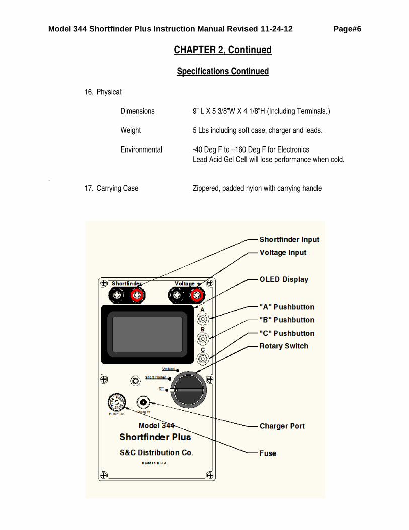
Refer to the drawing of the Shortfinder on page 6
A. Shortfinder Input is used when rotary switch is in the Shortfinder Position.
B. Voltage Input is used when the rotary switch is in the Voltage Position.
C. OLED Display displays all readings, menu options, and pushbutton options. Please
note that the internal battery voltage is displayed on the lower right of the display in
most modes.
D. “A” Pushbutton used to select options
E. “B” Pushbutton used to select options
F. “C” Pushbutton used to select options
G. Rotary Switch is used to select:
i. Power Off
ii. Shortfinder Mode
iii. Voltage Mode
H. Charger Port is used to recharge the internal Lead Acid Gel Cell and will allow
operation of the Shortfinder while charger is connected regardless of charge state.
I. Fuse, 3A fast blow fuse is used to protect instrument.
Model 344 Shortfinder Plus Instruction Manual Revised 11-24-12 Page#8
Chapter 3
How it works
AC/DC Voltmeter Function
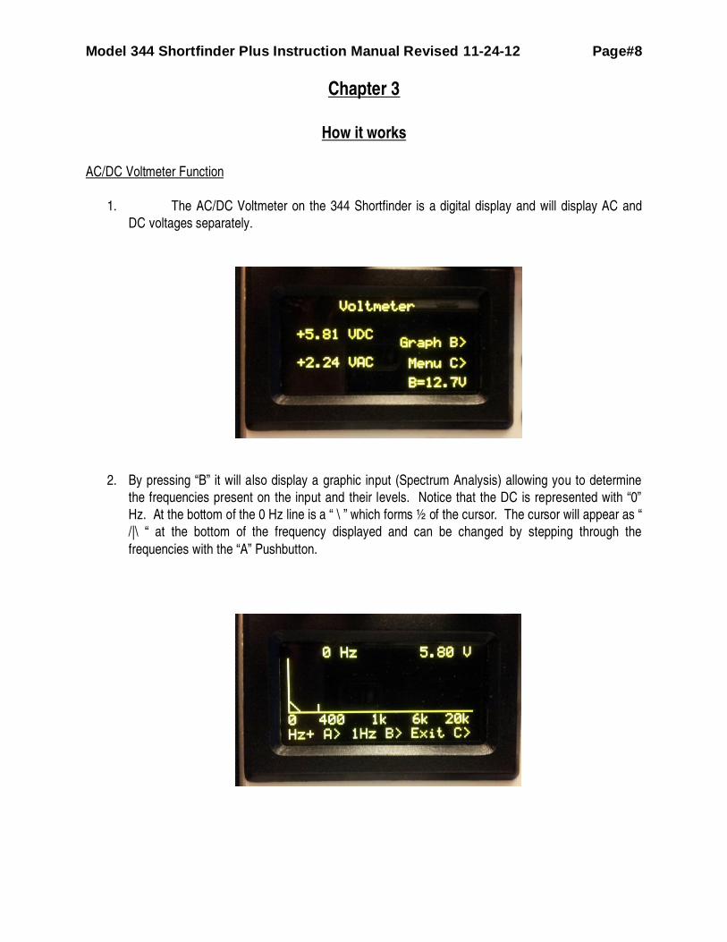
1. The AC/DC Voltmeter on the 344 Shortfinder is a digital display and will display AC and
DC voltages separately.
2. By pressing “B” it will also display a graphic input (Spectrum Analysis) allowing you to determine
the frequencies present on the input and their levels. Notice that the DC is represented with “0”
Hz. At the bottom of the 0 Hz line is a “ \ ” which forms ½ of the cursor. The cursor will appear as “
/|\ “ at the bottom of the frequency displayed and can be changed by stepping through the
frequencies with the “A” Pushbutton.

Model 344 Shortfinder Plus Instruction Manual Revised 11-24-12 Page#9
Chapter 3, Continued
How it works, Continued.
Voltmeter Function, Continued.
3. The 200 Hz frequency selected by (cursor on the 200 Hz Response ´/|\ ´) pressing “a”:
a. The frequency is reported on the upper left of the screen (200 Hz)
b. The voltage is reported on the upper right of the screen (2.23 V)
c. There are only 128 points on the display, so the accuracy of the frequency will be much
greater in the 1hz display, the selected frequency will be centered in the display.
4. You can now press the “B” Pushbutton to get a 1 Hz Display. This will expand the display centered
on the cursor position to display the frequencies in one Hz steps across the display.
5. This feature is useful if you suspect interference from adjacent circuits. You will notice that the
frequencies in this example run from 136Hz to 263 Hz across the bottom of the display where in
the previous example before the zoom all the frequencies from DC to 20Khz are shown. There are
128 pixels across the display, and it will show a response to any frequency in that range (128 Hz
wide) on the zoom screen, and will be centered where the cursor was placed before pressing the
“B” Pushbutton.

Model 344 Shortfinder Plus Instruction Manual Revised 11-24-12 Page#10
Chapter 3
How it works, Continued.
Shortfinder Function
I. When you turn the rotary switch to the first CW position (Shortfinder) the unit displays the
Calibration screen:
II. Hold the leads (plugged into the Shortfinder Input) together and press “C”:
A. The unit will calibrate the lead resistance in both 3 Khz and 24 Khz.
B. The Shortfinder is now ready for use and shows the resistance of the leads as 0.00 Ohms:

Model 344 Shortfinder Plus Instruction Manual Revised 11-24-12 Page#11
Chapter 3 Continued
How it works, Continued.
Shortfinder Function Continued.
III. When the leads are released (not held together) the Shortfinder will report:
A. That you are using 24 Khz Frequency
B. 0.0 and a small mark for the start of the bar graph.
C. >150 Ohms (Greater than 150 Ohms)
D. The Last Saved (value or reading) was also >150 Ohms. (this value will depend on what
you measured last.)
IV. The Model 344 Shortfinder Plus is designed to output a user selectable 3.0 Khz or 24 Khz AC
Voltage into the track, line, or cable circuitry being checked. Components within the Shortfinder generate
an appropriate sine wave frequency which is then applied to the output filters which are series tuned at 3
and 24 Khz respectively. The Output is then monitored to determine the resistance applied to the
Shortfinder input. A processor controls the frequency based on a crystal oscillator, does the
measurements, and displays the results on the OLED Display.
V. There are two 2 Ohm resistors in series with the output and this resistance and the pass band
characteristics of the output filters determine the output impedance of the Shortfinder. In no conditions will
it be lower than 4 ohms and that is just at 3 Khz and 24 Khz.
VI. The signal is taken into the processor where an electronic filter is applied for response only on the
frequency selected by pressing “A” pushbutton of either 3 or 24 Khz.,
VII. The processor then determines the resistance across the Shortfinder terminals based on the
calibration value saved when the Shortfinder was turned on and the leads shorted.
VIII. When Shortfinder is not connected to anything, it will report >150 Ohms.
IX. When applied to a track, the Shortfinder will, under normal circumstances, report between 1 and
100 ohms depending on the ballast conditions of the track.
Model 344 Shortfinder Plus Instruction Manual Revised 11-24-12 Page#12
Chapter 3 Continued
How it works, Continued.
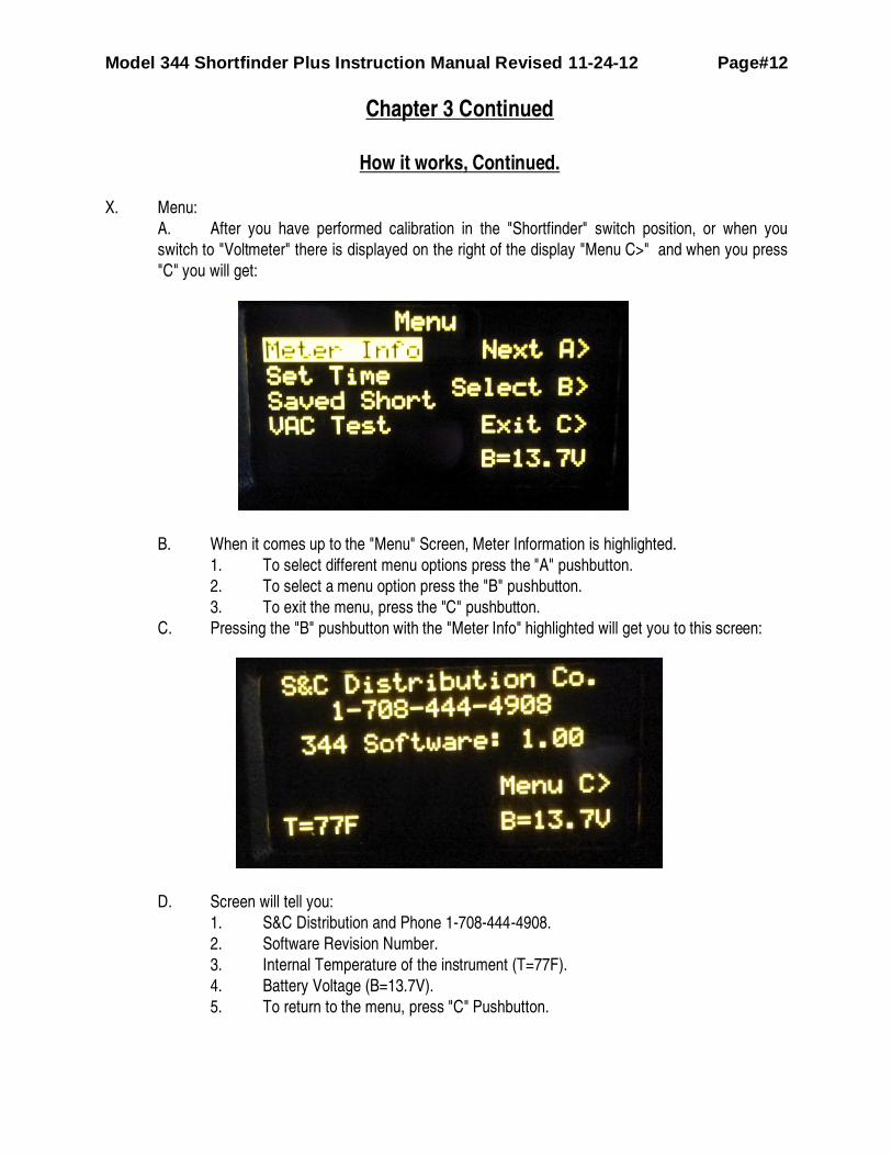
X. Menu:
A. After you have performed calibration in the "Shortfinder" switch position, or when you
switch to "Voltmeter" there is displayed on the right of the display "Menu C>" and when you press
"C" you will get:
B. When it comes up to the "Menu" Screen, Meter Information is highlighted.
1. To select different menu options press the "A" pushbutton.
2. To select a menu option press the "B" pushbutton.
3. To exit the menu, press the "C" pushbutton.
C. Pressing the "B" pushbutton with the "Meter Info" highlighted will get you to this screen:
D. Screen will tell you:
1. S&C Distribution and Phone 1-708-444-4908.
2. Software Revision Number.
3. Internal Temperature of the instrument (T=77F).
4. Battery Voltage (B=13.7V).
5. To return to the menu, press "C" Pushbutton.

Model 344 Shortfinder Plus Instruction Manual Revised 11-24-12 Page#13
Chapter 3 Continued
How it works, Continued.
E. Pressing the "A" Button at the "Menu" screen will highlight "Set Time", then pressing the
"B" button will take you to this screen:
F. If the current time is correct then you can press "C" Pushbutton to go back to the main
menu.
G. If you wish to change the time or date, then press "B" Pushbutton to go to this screen:
H. You will notice that the first digit of the date is highlighted.
1. To change the digit, press the "A" Pushbutton, each successive press will
increment it by one count.
2. To move the cursor to the next digit, press the "B" Pushbutton.
3. When setting the time, remember to use military time, for instance use 13:00 for
1:00 PM.
4. Press "C" and it will set the time and take you back to the main function
(Shortfinder or Voltage).
5. The Time/Date must be valid, or the unit will not accept it.
Model 344 Shortfinder Plus Instruction Manual Revised 11-24-12 Page#14
Chapter 3 Continued
How it works, Continued.
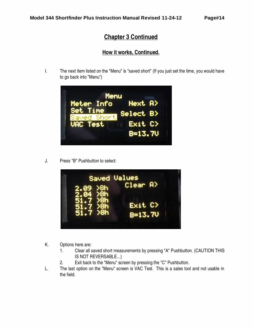
I. The next item listed on the "Menu" is "saved short" (If you just set the time, you would have
to go back into "Menu")
J. Press "B" Pushbutton to select:
K. Options here are:
1. Clear all saved short measurements by pressing "A" Pushbutton. (CAUTION THIS
IS NOT REVERSABLE...)
2. Exit back to the "Menu" screen by pressing the "C" Pushbutton.
L. The last option on the "Menu" screen is VAC Test. This is a sales tool and not usable in
the field.
Model 344 Shortfinder Plus Instruction Manual Revised 11-24-12 Page#15
Chapter 4
Application Procedures
A. General
1. These application procedures detail the methods that should be used to perform
specific types of checks on common DC track circuits and line or cable circuits. The
“Other Considerations” section (Section D) at the end of this chapter provides
additional information that you should keep in mind, including guidance concerning the
use of the Short Finder on portions of track equipped with coded DC track circuits or
audio overlay and/or motion responsive electronic track circuits. 2. You should be familiar with the proper way to use the Shortfinder in each of it’s
applications before trying to identify shorted or open track circuits. Depending on your
level of experience, in the beginning it would probably be best to perform the various
checks listed below exactly as they are described. As you gain understanding of how
the Shortfinder works you will discover ways to shorten the check procedures. After
you are familiar with the following procedures, apply them at the proper point (s) when
using the Guideline For Locating Shorted or Open Track Circuits (Chapter 5). 3. When looking for a short keep in mind that only a Zero (0) Ohm short will give you a 15
on the Bar Graph and 0.0 Ohms, at the short. The highest bar graph reading a one
half 0hm short will give you, at the short, is approximately 11 on the bar graph and 0.5
Ohms. Always look for the highest reading on the meter, not necessarily a peak of 15
on the bar graph and 0.0 Ohms. 4. We also recommend that you try out the Short Finder to get an understanding of how it
responds. It would be especially beneficial if you could introduce problems into track
circuits, especially in a turnout, and observe Short Finder performance. Doing this
prior to the time when a real problem requires the use of the Shortfinder will greatly
enhance your ability to use it.

Model 344 Shortfinder Plus Instruction Manual Revised 11-24-12 Page#16
Chapter 4, Continued.
Application Procedures, Continued.
B. Safety
1. As always, it is important to follow all established safety procedures. Specific safety
issues to consider relative to the Shortfinder are as follows:
i. Be sure to get track time.
ii. The Shortfinder generates, one at a time, two different frequencies (3KHz and
24 KHz). If audio overlay or motion responsive track circuits are present on
the track you are checking, determine which frequencies these circuits
employ.
iii. The Shortfinder, under some circumstances, might activate motion responsive
track circuits. Be alert to the possibility of this possibility.
C A U T I O N
NOTE THAT THE MODEL 344 SHORTFINDER SHOULD NOT BE EXPOSED
TO AC VOLTAGES GREATER THAN 160VAC NOR DC VOLTAGES
GREATER THEN 250VDC. DAMAGE MAY RESULT.
C. Shortfinder Calibration:
1. Turn rotary switch one click clockwise from "Off" to "Shortfinder". 2. 344 will ask you to short the leads and press “C” to calibrate. 3. 344 will then take calibration readings at both 3 KHz and 24 KHz then storing the
results for the present tests you wish to perform. 4. 344 will ask to be calibrated each time the rotary switch is moved to the Shortfinder
position from either off or from Voltage.

Model 344 Shortfinder Plus Instruction Manual Revised 11-24-12 Page#17
Chapter 4, Continued.
Application Procedures, Continued.
D. Checking Track Circuits:
1. Determining the presence of a Short or Open –
i. When you use the Voltmeter in the Shortfinder keep in mind that it is provided
as an indicator, not a test device. The accuracy of the voltmeter is +/- 3%.
ii. As long as there is an AC or DC signal on the track that can be measured, the
voltmeter built into the Shortfinder can be used to help determine it the false
track occupancy indication (track circuit failure) is due to a short, partial short,
or open. Use the Voltmeter to read rail-to-rail. High or full voltage suggests
an open. Low or no voltage suggests a partial or full short.
iii. It is easiest to use the Voltmeter to find open circuits.
iv. It is easiest to use the Shortfinder to find shorted, grounded, or partially
shorted or grounded circuits.
2. Using the Voltmeter to find an Open - From any point in the circuit, check the rail-to-
rail voltage.
i. If no voltage is present:
a) Walk toward the battery or transmitter end of the circuit taking rail-to-
rail readings every 40-50 paces.
b) When a normal track voltage reading appears on the meter, reverse
direction taking rail-to-rail readings every three paces.
c) When the normal track voltage reading disappears, you are in the
vicinity of the open.
ii. If normal track voltage is present:
a) Walk toward the end of the circuit taking rail-to-rail readings every 40 -
50 paces.
b) When the normal track voltage reading disappears, reverse direction
taking rail-to-rail readings every three paces.
Model 344 Shortfinder Plus Instruction Manual Revised 11-24-12 Page#18
Chapter 4, Continued.
Application Procedures, Continued.
c) When the normal track voltage reading reappears, you are in the
vicinity of the open.
3. Using the Shortfinder –
i. After you have used the Voltmeter to determine that a short or partial short is
causing the false track occupancy indication (track circuit failure) you can use
the Shortfinder to locate the short or partial short.
ii. Turn on the Shortfinder and follow the calibration instructions.
iii. Keep in mind that only a Zero ohm shunt will give you a bar graph of 15 or 0.0
ohms, at the short. The highest bar graph or lowest ohm reading a ½ Ohm
shunt will give you is approximately 11 or 0.5 Ohms. Always look for the
highest bar graph (lowest ohms) reading on the display, not necessarily a
peak (15) reading.
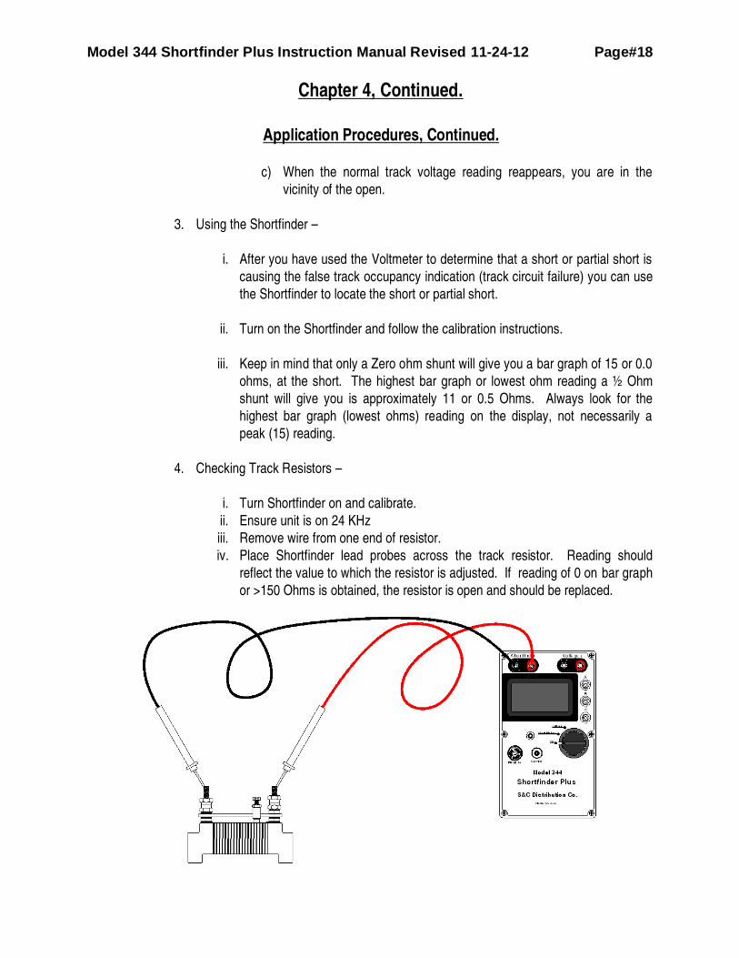
4. Checking Track Resistors –
i. Turn Shortfinder on and calibrate.
ii. Ensure unit is on 24 KHz
iii. Remove wire from one end of resistor.
iv. Place Shortfinder lead probes across the track resistor. Reading should
reflect the value to which the resistor is adjusted. If reading of 0 on bar graph
or >150 Ohms is obtained, the resistor is open and should be replaced.
Model 344 Shortfinder Plus Instruction Manual Revised 11-24-12 Page#19
Chapter 4, Continued.
Application Procedures, Continued.
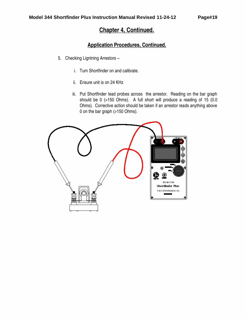
5. Checking Ligntning Arrestors –
i. Turn Shortfinder on and calibrate.
ii. Ensure unit is on 24 KHz
iii. Put Shortfinder lead probes across the arrestor. Reading on the bar graph
should be 0 (>150 Ohms). A full short will produce a reading of 15 (0.0
Ohms). Corrective action should be taken if an arrestor reads anything above
0 on the bar graph (>150 Ohms).
Model 344 Shortfinder Plus Instruction Manual Revised 11-24-12 Page#20
Chapter 4, Continued.
Application Procedures, Continued.
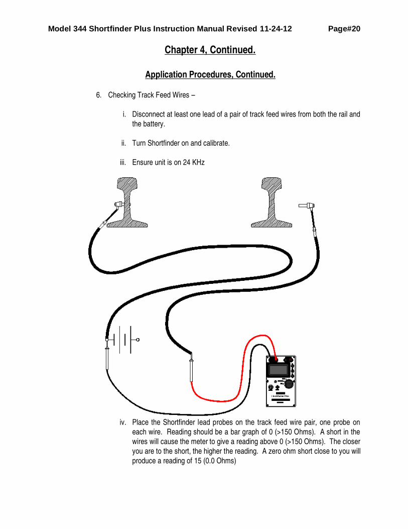
6. Checking Track Feed Wires –
i. Disconnect at least one lead of a pair of track feed wires from both the rail and
the battery.
ii. Turn Shortfinder on and calibrate.
iii. Ensure unit is on 24 KHz
iv. Place the Shortfinder lead probes on the track feed wire pair, one probe on
each wire. Reading should be a bar graph of 0 (>150 Ohms). A short in the
wires will cause the meter to give a reading above 0 (>150 Ohms). The closer
you are to the short, the higher the reading. A zero ohm short close to you will
produce a reading of 15 (0.0 Ohms)

Model 344 Shortfinder Plus Instruction Manual Revised 11-24-12 Page#21
Chapter 4, Continued.
Application Procedures, Continued.
7. Checking Track Insulation (Insulated Joints, Gauge Plates, & Switch Rod Insulation) –
i. Turn Shortfinder on and calibrate.
ii. Ensure unit is on 24 KHz
iii. Take a rail-to-rail reading approximately 150 feet from anything that might be
shorted. This reading is a benchmark value that you can use to compare
readings taken across track insulation. This reading is a bar graph reading of
between 1 and 6 (20 Ohms to 2 ohms).
iv. Place Shortfinder lead probes directly across the insulating material.
Readings should be between 1 and 6 (20 Ohms to 2 Ohms). One railroad has
determined if the reading is 12 or above (around .3 Ohms) the insulating
material should be replaced.
v. If you suspect the insulated joint is intermittently shorted, our Rail Clamp
Connector Set (PN: 324-31 can facilitate maintaining Shortfinder connection
while using the time-honored hammer technique for verifying the intermittent.
vi. When evaluating track insulation, keep in mind the following:
a) VERY IMPORTANT! When you find a joint that reads high, and
you suspect that it is bad, read other joints in the area. If other track
insulation at the location you are checking has the same high reading,
even if the reading is very high, they probably are not shorted. See
“c)” below.
b) A short in one joint may influence readings in an adjacent joint.
Before deciding that track insulation should be replaced be sure it is
the element with the highest reading. Normally, when corrective
action is taken on the insulating material with the highest reading the
readings on other insulation will return to normal. If they do not, check
the element that now has the highest reading.
c) Unless you have track signals in the 3 KHz range, the Model 344
should be immune to interfering signals on the track including
induction.
Model 344 Shortfinder Plus Instruction Manual Revised 11-24-12 Page#22
Chapter 4, Continued.
Application Procedures, Continued.
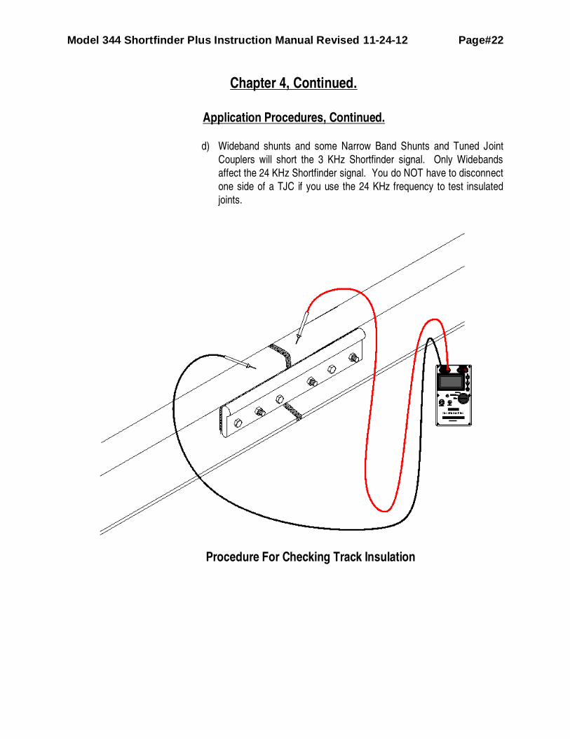
d) Wideband shunts and some Narrow Band Shunts and Tuned Joint
Couplers will short the 3 KHz Shortfinder signal. Only Widebands
affect the 24 KHz Shortfinder signal. You do NOT have to disconnect
one side of a TJC if you use the 24 KHz frequency to test insulated
joints.
Procedure For Checking Track Insulation

Model 344 Shortfinder Plus Instruction Manual Revised 11-24-12 Page#23
Chapter 4, Continued.
Application Procedures, Continued.
Procedure for Checking Rail-to-Rail
8. Checking Rail-to-Rail (Switch rod insulation, gauge plate insulation, closure rail
insulated joints, locating pockets of low ballast resistance, banding buried in the
ballast etc…)
i. Note the drawing above. This drawing describes how to check rail-to-rail. Bar
Graph values, and ohms are representative of those you will find, NOT actual.
And the number of sets of paces will depend on how far you are from the
short.
ii. Begin check with the Shortfinder on 3 KHz setting.
iii. Place Shortfinder lead probes rail-to-rail. A normal reading is between 1 and 6
(20 Ohms to 2 ohms).
Model 344 Shortfinder Plus Instruction Manual Revised 11-24-12 Page#24
Chapter 4, Continued.
Application Procedures, Continued.
iv. Move in the direction that increases the readings (larger bar graph, smaller
ohms reading) taking readings every 40 to 50 paces until you have a reading
of between 8.5 (1 Ohm) and 12 (0.3 Ohms).
v. Change the frequency to 24 KHz and continue moving at 15 pace intervals in
the direction of increasing reading on the bar graph (lower ohms) until you
again have a reading of between 8.5 (1 Ohm) and 12 (0.3 Ohms).
vi. Now reduce the distance between readings to every 3 feet.
vii. Continue taking readings until the highest reading (lowest ohms) is obtained.
At this point you have located the short.
viii. At any point in the process, if your readings start decreasing (ohms increase)
you will have to backtrack. You have walked past the short.
ix. When evaluating switch rod and gauge plate insulation, keep in mind that a
short in one insulation set may influence readings in an adjacent set. Before
deciding that a particular insulation set should be replaced be sure it is the set
with the highest reading (lowest ohms). Normally when corrective action is
taken on the insulation set with the highest reading the readings on the other
sets will return to normal. If they do not, check the insulation set that now has
the highest reading. Remember to check switch rod and gauge plate
insulation by reading directly across the insulating material not rail-to-rail.
9. Checking Bonds or Track Connections for High Resistance –
i. Turn Shortfinder on and calibrate.
ii. Ensure unit is on 24 KHz
iii. Place Shortfinder lead probes across each bond termination or track
connection. One probe should be on the rail and the other on the conductor
behind the rail termination. Check each bond or track connection this way.
iv. Readings should be 15 (0.0 Ohms). Readings of less than 15 (0.0 Ohms)
indicate the presence of undesirable resistance and corrective action should
be taken. Readings of 13 (0.2 Ohms) instead of 15 (0.0 Ohms) is sufficient to
make that connection “open” to a motion responsive track circuit.

Model 344 Shortfinder Plus Instruction Manual Revised 11-24-12 Page#25
Chapter 4, Continued.
Application Procedures, Continued.
v. Before replacing a bond or track connection that indicates high resistance,
make sure your Shortfinder lead probes are making solid connection with the
rail and bond or track wire terminal. For this application we recommend the
use of our Quick-Read Probe Tips or File Probe accessories.
10. If you suspect an intermittent connection, the Shortfinder allows one man check for
this condition.
i. Turn Shortfinder on and calibrate.
ii. Ensure unit is on 24 KHz
iii. Place the Shortfinder where you can observe it.
iv. With one hand, hold the Shortfinder probes against the rail ends that are
bonded, one probe on each rail end.
v. Wiggle the bond with a screwdriver or tap each bond terminal with a hammer,
using your free hand.
a) Any bar graph movement indicates looseness or high resistance.
Corrective action should be taken.
b) Similar action can be taken to check a track feed wire connection to
the rail, by holding the Shortfinder probes against the rail and track
feed wire involved.
Model 344 Shortfinder Plus Instruction Manual Revised 11-24-12 Page#26
Chapter 4, Continued.
Application Procedures, Continued.
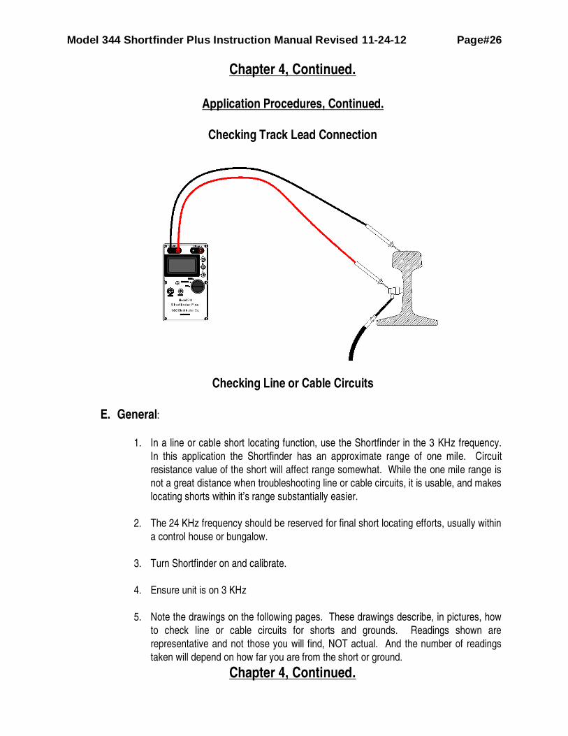
Checking Track Lead Connection
Checking Line or Cable Circuits
E. General:
1. In a line or cable short locating function, use the Shortfinder in the 3 KHz frequency.
In this application the Shortfinder has an approximate range of one mile. Circuit
resistance value of the short will affect range somewhat. While the one mile range is
not a great distance when troubleshooting line or cable circuits, it is usable, and makes
locating shorts within it’s range substantially easier.
2. The 24 KHz frequency should be reserved for final short locating efforts, usually within
a control house or bungalow.
3. Turn Shortfinder on and calibrate.
4. Ensure unit is on 3 KHz
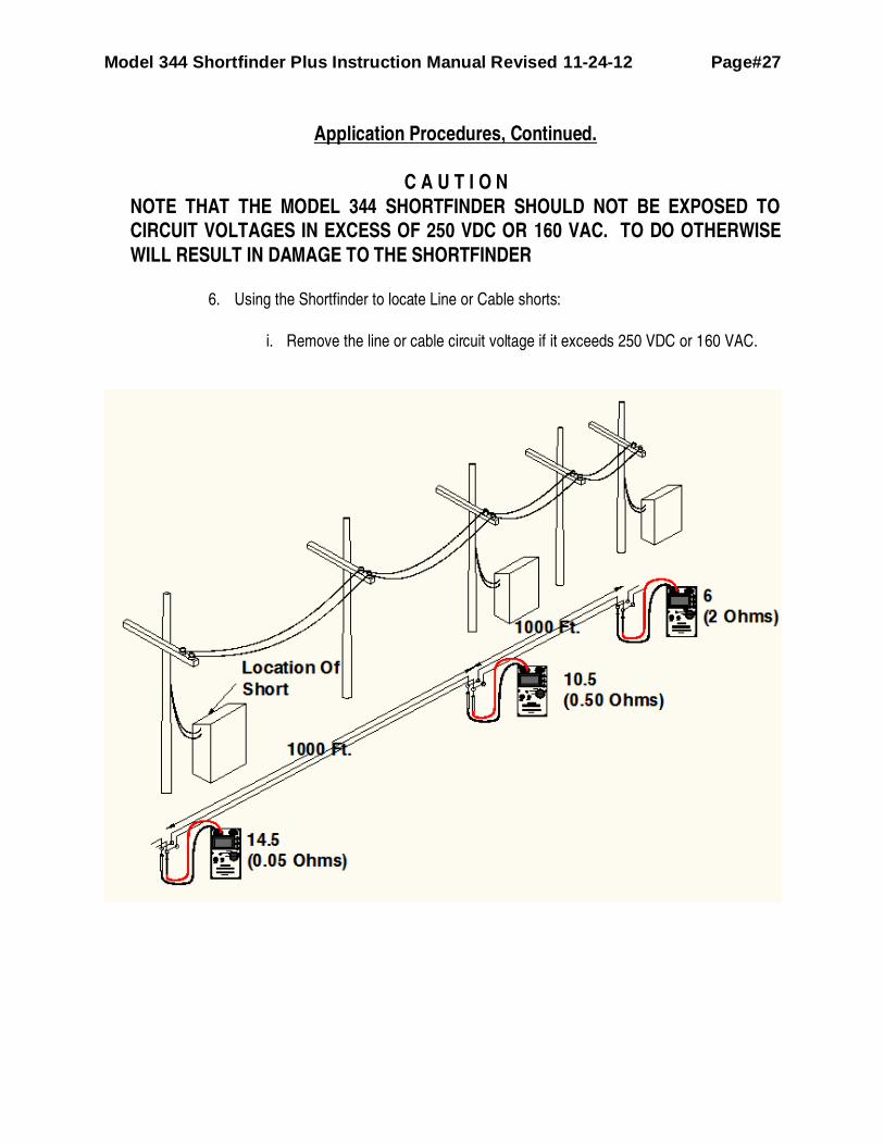
5. Note the drawings on the following pages. These drawings describe, in pictures, how
to check line or cable circuits for shorts and grounds. Readings shown are
representative and not those you will find, NOT actual. And the number of readings
taken will depend on how far you are from the short or ground.
Chapter 4, Continued.
Model 344 Shortfinder Plus Instruction Manual Revised 11-24-12 Page#27
Application Procedures, Continued.
C A U T I O N
NOTE THAT THE MODEL 344 SHORTFINDER SHOULD NOT BE EXPOSED TO
CIRCUIT VOLTAGES IN EXCESS OF 250 VDC OR 160 VAC. TO DO OTHERWISE
WILL RESULT IN DAMAGE TO THE SHORTFINDER
6. Using the Shortfinder to locate Line or Cable shorts:
i. Remove the line or cable circuit voltage if it exceeds 250 VDC or 160 VAC.

Model 344 Shortfinder Plus Instruction Manual Revised 11-24-12 Page#28
Chapter 4, Continued.
Application Procedures, Continued.
ii. Place Shortfinder lead probes across the shorted line or cable pair. A normal
wire to wire reading is 0.0 (.>150 Ohms); although it can be in the 1 to 3 (20.0
ohms to 5.0 Ohms) range, if the line or cable pair is connected to a relay or
other circuit completing device.
iii. Move in the direction that increases readings on the bar graph (decreasing
ohms) taking readings every 1000 feet or more, until you have a reading of
between 8.5 (1 Ohm) and 12 (0.3 Ohms).
iv. Change the frequency to 24 KHz and continue moving in the direction of
increased bar graph readings (lower ohms) until you have a reading of
between 8.5 (1 Ohm) and 12 (0.3 Ohms).
v. At this point you are probably very near the location of the short. Continue
taking readings until the highest reading (lowest ohms) is obtained. At this
point you have located the short. When looking for a short keep in mind that
only a Zero Ohm short will give you a bar graph reading of 15 (0.0 Ohms), at
the short. The highest bar graph reading for a ½ Ohm short is approximately
11. Always look for the highest reading on the meter, not necessarily a peak
(15 or 0.0 Ohms) reading.
7. Using the Shortfinder to locate line or cable grounds:
i. Remove the line or cable circuit voltage source if it exceeds 250 VDC or 160
VAC.
ii. Place the Shortfinder lead probes across the grounded line or cable wire and
the ground buss or terminal. A normal wire to ground reading is Zero on the
bar graph (>150 Ohms).
iii. Move in the direction that increases the bar graph reading (decreasing Ohms),
taking readings every 1000 feet or more, until you have a reading of between
8.5 (1 Ohm) and 12 (0.3 Ohms).
iv. Change the frequency to 24 KHz and continue moving in the direction of
increased bar graph readings (lower Ohms) until you have a reading of
between 8.5 (1 Ohm) and 12 (0.3 Ohms).

Model 344 Shortfinder Plus Instruction Manual Revised 11-24-12 Page#29
Chapter 4, Continued.
Application Procedures, Continued.
v. At this point you are probably very near the location of the ground. Continue
taking readings until the highest reading is obtained. At this point you have
located the ground. When looking for a ground keep in mind that only a Zero
Ohm ground will give you a bar graph reading of 15 (0.0 Ohms), at the ground
The highest bar graph reading for a ½ Ohm short is approximately 11. Always
look for the highest reading on the meter, not necessarily a peak (15 or 0.0
Ohms) reading.
F. Other Considerations and Uses
1. When checking track and it’s components keep in mind that contamination normally
found on the rail can artificially lower bar graph readings (report higher Ohmic values).
It is helpful to either have a file on-hand to clear away the rust, grease, scale, etc, or
use our Quick Read Probe Tips or File Probes accessories. 2. The amount of pressure used to maintain the probes against the rail can influence
readings. Pressure should be firm, but not so great that the probes are bent in the
process. Light pressure will result in an inaccurate meter reading. Our File Probes are
sturdy enough to allow greater pressure without causing any damage to the
probes/leads.
Model 344 Shortfinder Plus Instruction Manual Revised 11-24-12 Page#30
Chapter 4, Continued.
Application Procedures, Continued.
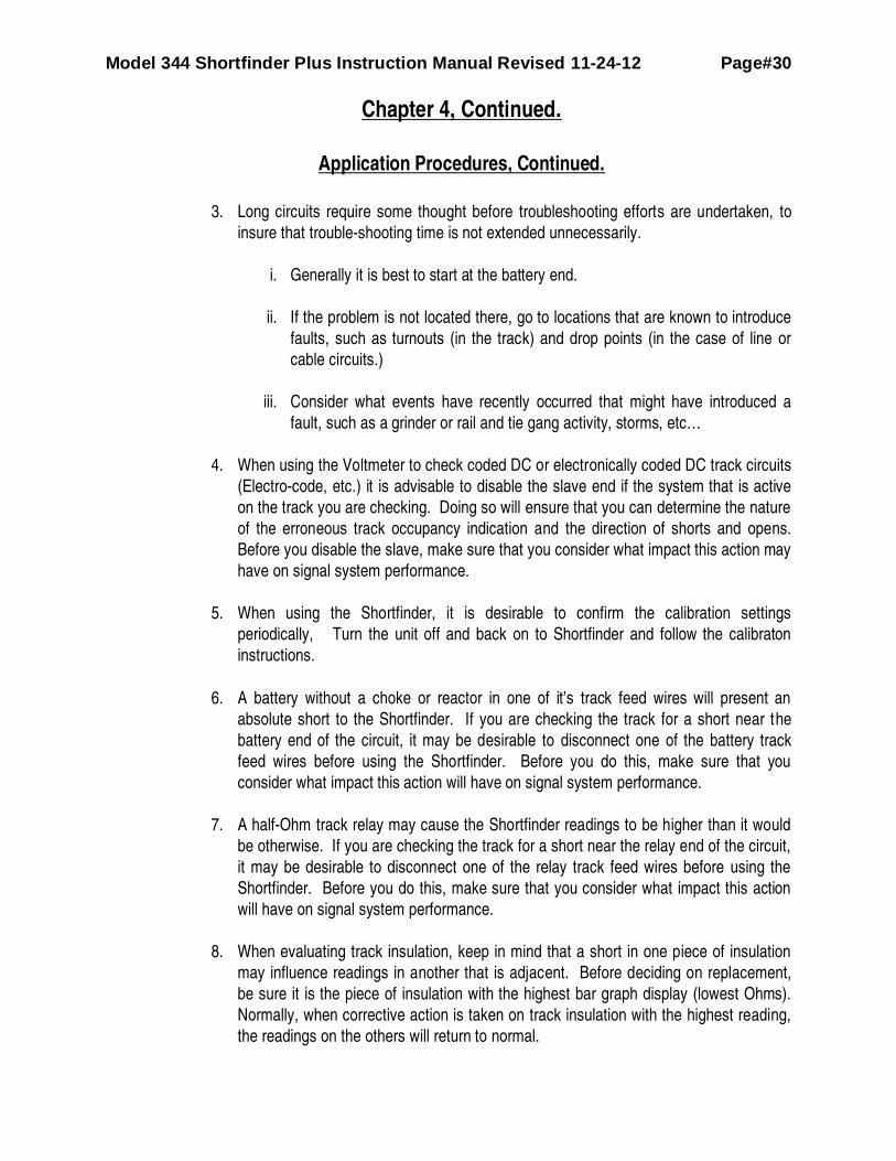
3. Long circuits require some thought before troubleshooting efforts are undertaken, to
insure that trouble-shooting time is not extended unnecessarily.
i. Generally it is best to start at the battery end.
ii. If the problem is not located there, go to locations that are known to introduce
faults, such as turnouts (in the track) and drop points (in the case of line or
cable circuits.)
iii. Consider what events have recently occurred that might have introduced a
fault, such as a grinder or rail and tie gang activity, storms, etc…
4. When using the Voltmeter to check coded DC or electronically coded DC track circuits
(Electro-code, etc.) it is advisable to disable the slave end if the system that is active
on the track you are checking. Doing so will ensure that you can determine the nature
of the erroneous track occupancy indication and the direction of shorts and opens.
Before you disable the slave, make sure that you consider what impact this action may
have on signal system performance.
5. When using the Shortfinder, it is desirable to confirm the calibration settings
periodically, Turn the unit off and back on to Shortfinder and follow the calibraton
instructions.
6. A battery without a choke or reactor in one of it’s track feed wires will present an
absolute short to the Shortfinder. If you are checking the track for a short near the
battery end of the circuit, it may be desirable to disconnect one of the battery track
feed wires before using the Shortfinder. Before you do this, make sure that you
consider what impact this action will have on signal system performance.
7. A half-Ohm track relay may cause the Shortfinder readings to be higher than it would
be otherwise. If you are checking the track for a short near the relay end of the circuit,
it may be desirable to disconnect one of the relay track feed wires before using the
Shortfinder. Before you do this, make sure that you consider what impact this action
will have on signal system performance.
8. When evaluating track insulation, keep in mind that a short in one piece of insulation
may influence readings in another that is adjacent. Before deciding on replacement,
be sure it is the piece of insulation with the highest bar graph display (lowest Ohms).
Normally, when corrective action is taken on track insulation with the highest reading,
the readings on the others will return to normal.
Model 344 Shortfinder Plus Instruction Manual Revised 11-24-12 Page#31
Chapter 4, Continued.
Application Procedures, Continued.
9. 344 Shortfinder readings are basically not affected by other signals on the track
produced by overlay and motion sensing unless they are either 3 KHz or 24 KHz. The
344 Shortfinder will also not interfere with most overlay and motion sensors unless
they are 3 KHz or 24 KHz. If you suspect interference by another device, then disable
these transmitters and observe if any effect is on the 344 Shortfinder. Before you do
this, make sure that you consider what impact this action will have on signal system
performance.
10. When taking rail-to-rail readings with the Shortfinder to check a track circuit through a
turnout, keep in mind that if the short is in the polarity joint or in the fouling circuit itself,
the Shortfinder reading will climb as you approach the fouling jumper, to a peak of 6 to
8 (between 1 and 2 ohms), depending on the degree of the short. With such an
indication, check the polarity joint and the fouling circuit.
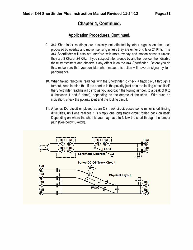
11. A series DC circuit employed as an OS track circuit poses some minor short finding
difficulties, until one realizes it is simply one long track circuit folded back on itself.
Depending on where the short is you may have to follow the short through the jumper
path (See below Sketch).

Model 344 Shortfinder Plus Instruction Manual Revised 11-24-12 Page#32
Chapter 4, Continued.
Application Procedures, Continued.
12. The 344 Shortfinder should not interfere with crossing warning systems when Rail-to-
Rail readings are taken in the area of a crossing,
13. Before checking insulated joints, be sure to disconnect the leads to one side of any
wideband shunt that may be by-passing the joint. Before you do this, make sure that
you consider what impact this action will have on crossing warning system
performance.
14. If a Tuned/Tunable Joint Coupler (TJC) is used to bypass an insulated joint, use the 24
KHz frequency to check the joint. The 24 KHz frequency will not pass through the
TJC, thus the reading obtained with the Shortfinder will accurately reflect the condition
of the joint. If you get a high reading, you will have to determine whether the Joint or
the TJC is shorted.
15. The 344 Shortfinder should not be used to test narrow band shunts or couplers.
Please use the Model 322 Shunt Coupler Tester for that.
16. Be advised that a dummy load in series with a shorted wide or narrow band shunt can
mask a track circuit short from the Shortfinder. If the Voltmeter indicates that there is a
short on the circuit, but the Shortfinder does not register a definite peak reading, go to
any location in the circuit that has a dummy load in series with the shunt, and check
the shunt for a short.
17. While the product is titled “Shortfinder” the unit also “sees” partial shorts such as bad
ballast conditions. A high current flow in a track circuit may not be a short, but
accumulated low ballast resistance (higher bar graph readings, lower resistance). On
the next page is a graph of readings taken every 300 ft (50 ft between readings when
a large change was registered) across a 14,000 foot track circuit. As you can see, this
effort produced a graph that identified pockets of bad ballast that were causing the
track circuit to draw excessive current. The specific locations indicated by the high
Shortfinder readings (low ballast resistance) were ballast-cleaned and the track circuit
was restored to normal operating current level.
18. If you are going to test your testing shunts for proper resistance value, be sure to use
the 3 KHz frequency. In this application elimination of any contact resistance is
critical, both during calibration and when you are taking readings. To test a shunt,
connect across the entire shunt ensuring that your connection points with the
Shortfinder are on the tips that actually make electrical connection to the rail (not the t-
screw or clamp itself). Typical readings at 3Khz across a .06 Ohm Shunt will be
around .08 to .09 Ohms or around 13.90 on the Bar Graph (effect of inductance at 3
Khz.) A HW Shunt will measure around .03 Ohms or around 14.60 on the bar graph.
Keep in mind that any screwed in component may be high-resistance. Look for minor
increases over the values specified for the shunt to indicate a bad shunt. Frequently
the increases are surprisingly large.
Model 344 Shortfinder Plus Instruction Manual Revised 11-24-12 Page#33
Chapter 4, Continued.
Application Procedures, Continued.
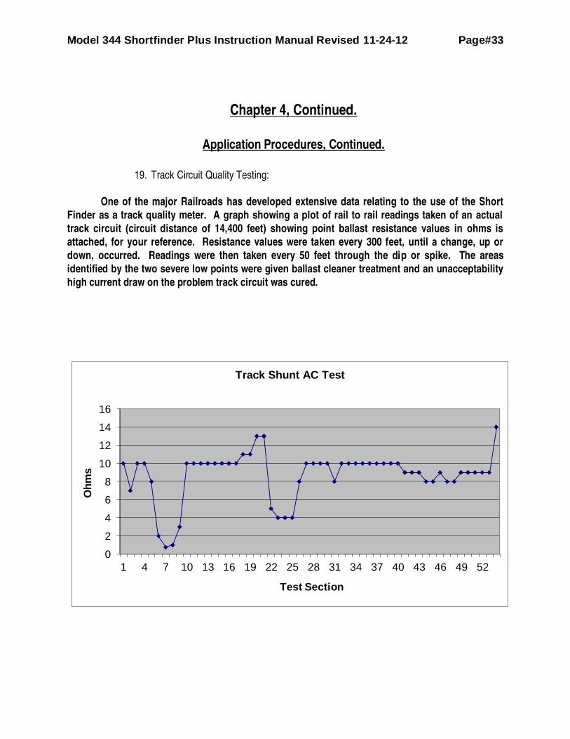
19. Track Circuit Quality Testing:
One of the major Railroads has developed extensive data relating to the use of the Short
Finder as a track quality meter. A graph showing a plot of rail to rail readings taken of an actual
track circuit (circuit distance of 14,400 feet) showing point ballast resistance values in ohms is
attached, for your reference. Resistance values were taken every 300 feet, until a change, up or
down, occurred. Readings were then taken every 50 feet through the dip or spike. The areas
identified by the two severe low points were given ballast cleaner treatment and an unacceptability
high current draw on the problem track circuit was cured.
0
2
4
6
8
10
12
14
16
1 4 7 10 13 16 19 22 25 28 31 34 37 40 43 46 49 52
Oh
ms
Test Section
Track Shunt AC Test

Model 344 Shortfinder Plus Instruction Manual Revised 11-24-12 Page#34
CHAPTER 5
Guidelines for Locating Shorted or Open Track Circuits
A. General
1. Before beginning the process of locating shorted or open track circuits, be sure
you are thoroughly familiar with the Applications Procedures provided in this manual. Be
especially familiar with the “Other Considerations” portion (Section F) of the applications
Procedures chapter. This portion of the manual provides information on factors that can
significantly influence the results you achieve with the Shortfinder.
2. Use the flow charts provided on the accompanying pages, and the check
described in the Applications Procedures (Chapter 4) of this manual to help you identify
shorted or open track circuits and locate causes.
B. Safety
The following material provides a step-by-step process for locating shorted or open track circuits.
As always, it is important to follow all established safety procedures. Specific safety issues to
consider relative to the Shortfinder are as follows:
1. Get proper roadway worker authority or protection in place (Track and Time) and
participate in a job briefing prior to fouling the track. Be aware of trains and keep vigilant
for your own personal safety.
2. The Shortfinder generates, one at a time, two different frequencies (3 KHz and 24
KHz). If audio overlay and motion responsive type track circuits are present on the track
you are checking, determine which frequencies these circuits employ. Older versions (un-
modulated) overlay and motion responsive might be affected by the Shortfinder. Be alert
to this possibility when checking for partial shorts.
3. Shortfinder Application Procedures at times suggest disconnecting various circuit
components from their operational status. Before you take any of these steps consider
what impact your actions may have on signal system or crossing warning system
performance.
4. Note that the model 344 Shortfinder should NOT be exposed to circuit voltages in
excess of 250 VDC or 177 VAC. To do otherwise will result in damage to the Shortfinder.

Model 344 Shortfinder Plus Instruction Manual Revised 11-24-12 Page#35
CHAPTER 5, CONTINUED
Guidelines for Locating Shorted or Open Track Circuits
C. Locating shorts at the Battery End of the Circuit:
Model 344 Shortfinder Plus Instruction Manual Revised 11-24-12 Page#36
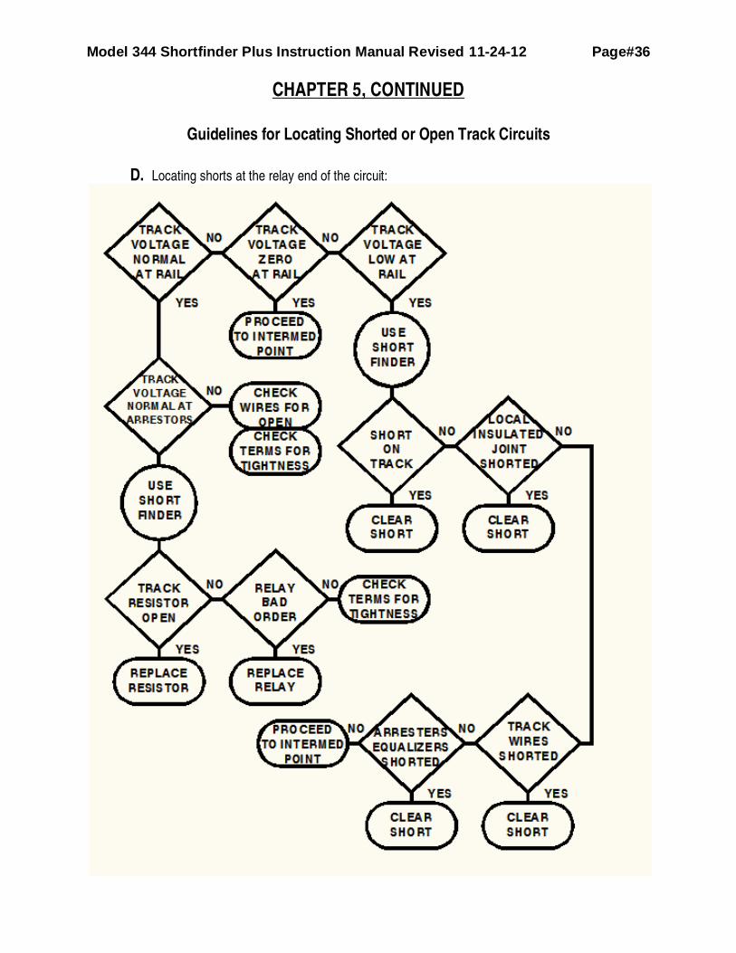
CHAPTER 5, CONTINUED
Guidelines for Locating Shorted or Open Track Circuits
D. Locating shorts at the relay end of the circuit:
Model 344 Shortfinder Plus Instruction Manual Revised 11-24-12 Page#37
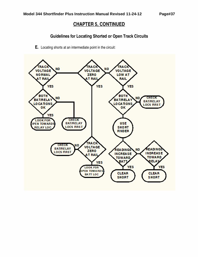
CHAPTER 5, CONTINUED
Guidelines for Locating Shorted or Open Track Circuits
E. Locating shorts at an intermediate point in the circuit:

Model 344 Shortfinder Plus Instruction Manual Revised 11-24-12 Page#38
CHAPTER 6
Accessories
A selected number of Accessories have been developed for the Shortfinder in response to customer
suggestions. They are detailed below. If you would like further information or pricing, contact S&C
Distribution Company.
A. Gel Cell Charger
PN: 324-40 80 to 264VAC Input, 12VDC 750 MA output, bulk, taper, float charger for the
1.2AH battery in the 344. Allows the use of standard commercial power to recharge depleted
12V Gel Cell in the 344 Shortfinder.
B. In-Vehilce Charging Adapter
PN: 324-12. Interface connector allows the use of your 12VDC Vehicle Battery to charge the
12VDC gell cell in the 344 Shortfinder. A 3A fuse in the cigarette lighter plug protects against
over current damage should a short develop. This charger works best when the engine is
running so that bulk charge can occur.
C. Shoulder Harness
PN: 324-20. Adjustable nylon shoulder strap with male and female snap clips that match those
on the Shortfinder Carrying Case. Provides means to carry the short finder hands-free, or to
support the Shortfinder off the ground while in use.
D. Quick Read Probe Tips
PN: 324-18. Quick Read Probe Tips enable the Shortfinder to read through rail contamination
without prior filing or cleaning. These Tips screw securely to the threaded shoulders of the
probes on the test leads furnished with the Shortfinder, providing solid electrical connections.
Clear readings are achieved using this method.
E. File Probes Set
PN: 324-25. Most effective method for eliminating contact resistance when taking Shortfinder
readings. File Probes deliver extended reach and mechanical advantage. Take accurate
readings, easily, through rust, grease and other rail contaminants. Each File/handle measures
12 in. long Leads are each four ft. long and are made of low temperature lead wire.
F. Dual-Blade Probe Set
PN: 324-28A. Provides a mid range alternative between the Quick-Read Probe Tips and the
File Probes. The Dual-Blade configuration stiffens the assembly and the four inch handle
provides some additional reach and mechanical advantage without significantly adding to the
weight. Take accurate Shortfinder readings through rust, grease and other rail contaminants.

Model 344 Shortfinder Plus Instruction Manual Revised 11-24-12 Page#39
CHAPTER 6, Continued
Accessories, continued
G. Meter Lead Rail Connector Set
PN: 324-31. Rugged, meter lead rail connector is based on S&C railroad grade head of rail
clamp. With these connectors, establish zero ohm connection to the rail that will permit you to
use your Shortfinder to check intermittent shorts in insulated joints, etc…

Model 344 Shortfinder Plus Instruction Manual Revised 11-24-12 Page#40
CHAPTER 7
Trouble-Shooting Guide
A. General
There are limited measures that can be taken to trouble-shoot the 344 Shortfinder. They are
described below. Instructions for returning the Shortfinder to the factory for repair are supplied
at the end of this chapter.
B. Trouble Shooting Procedures:
1. Unit fails to “Power Up” when turned on.
i. Check the 3A Fast Acting fuse on the front panel.
ii. Try Charging the Battery, the 344 will turn on and function with the charger
charging the battery.
iii. Shortfinder needs technician-level repair.
2. Voltmeter does not work:
i. Check to see if you moved the leads from the Shortfinder terminals to the
Voltmeter terminals.
ii. Make sure foreign material is not interfering with the probe connections.
iii. Make sure the banana plugs are securely in their jacks.
iv. Check leads for opens.
v. Shortfinder needs technician-level repair.
3. Shortfinder won’t calibrate, states “input open”
i. Leads plugged into wrong jack.
ii. Leads not shorted when “C” pressed.
iii. Leads defective.
iv. Shortfinder needs technician-level repair.

Model 344 Shortfinder Plus Instruction Manual Revised 11-24-12 Page#41
CHAPTER 7, CONTINUED.
Trouble-Shooting Guide, continued.
C. Returning the Shortfinder or Accessories for repair at the factory.
1. Call S&C Distribution Company for a Return Goods Authorization and shipping
instructions.
2. Pack the item being returned for repair carefully and ship it prepaid to the address
provided.
S&C Distribution Company
7225 Duvan Drive
Tinley Park, IL 60477
Phone: 1-708-444-4908
Fax: 1-708-444-4962
Email [email protected]