modbus rtu master communications - infi 90 infi90 documentation/ge fa… · · 2008-08-032 modbus...
TRANSCRIPT
GFK-2220A 1
Modbus RTU Master Communications
This document describes the operation of Modbus® RTU Master from the user interfacepoint of view. Use this information as a supplement to the Serial Communications User’sManual (GFK-0582). This document contains the following information:� Overview
� Supported Products� Mode of Operation� COMMREQs� Time Constraints
� Serial Connections� Standards� Multidrop Connections
� Drivers and Receivers� Cable� Grounding� Connector Wiring� Four-Wire� Two-Wire
� Point-to-Point� COMMREQ Function Block Format
� COMMREQ Function Block Parameters� COMMREQ Function Block Output� COMMREQ Command Data Block
� Modbus RTU Master Status Word Format� Queue Limitations for Modbus RTU Master COMMREQs� Local Data� Modbus RTU Master Diagnostic Status Words� Modbus RTU Master Commands
� Initialize RTU Master Port: 65520 (FFF0)� Clear RTU Master Diagnostic Status Words: 08000 (1F40)� Read RTU Master Diagnostic Status Words: 08001 (1F41)� Send RTU Read/Force/Preset Query: 08002 (1F42)� Send RTU Diagnostic Query: 08003 (1F43)
� Error Codes� Example Application
® Modbus is a registered trademark of Schneider Electric.

2 Modbus RTU Master Communications - December 2002
OverviewModbus Serial Line protocol is an open standard for data communications between PLCsand related devices. The Modbus Serial Line standard provides for communication usingeither printable characters exclusively (Modbus ASCII), or binary data (Modbus RTU).
This document describes Modbus RTU Master communications on GE Fanuc PLC CPUs.
Supported ProductsModbus RTU Master communications is currently available on the Series 90-30IC693CPU363 and VersaMax modular CPU models IC200CPU001, IC200CPU002,IC200CPU005 and IC200CPUE05.
Mode of OperationA Modbus RTU master device (the client) periodically sends query messages to one ormore slave devices (the servers) on a serial network. Queries may contain data, requestsfor data or status, or commands.
Each slave on the network has a unique device address. Any query may be addressedeither to a specific slave device or to a special broadcast address. Queries addressed to thebroadcast address are called broadcast queries. Queries that require a response may notbe addressed to the broadcast address.
A slave that receives a well-formed, non-broadcast query must send a response message tothe master. The query/response transaction completes when the master receives a well-formed response.
Slaves do not respond to broadcast queries. After sending a broadcast query, the mastermust wait a specified time before completing the transaction and sending the next query.Some broadcast queries contain commands that require the slaves to take specifiedactions.
COMMREQsThe application program running in the PLC CPU controls the timing and content of eachquery by sending a COMMREQ message. The COMMREQ must be addressed to theCPU serial port that is connected to the Modbus RTU serial network. COMMREQ dataspecifies the content of the query. When the query/response transaction completes, aCOMMREQ status value indicates the success or failure of the transaction. See theCOMMREQ Function Block Format section of this document and the sections that followit for details.
Time ConstraintsThe Modbus Serial Protocol Reference Guide1 contains several important timingrequirements
1 The current Modbus RTU specification is available online in the document Modbus SerialProtocol Reference Guide at http://www.modbus.org/. Follow the Modbus Standard Library linkto find it.

GFK-2220A Modbus RTU Master Communications 3
Serial ConnectionsA Modbus RTU network has one master device and one or more (up to 247) slave devices.A serial network interconnects all these devices. If there is only one slave, a point-to-point connection is used. A multidrop connection is needed for two or more slaves.
StandardsVirtually all PLC serial communications ports (including all serial ports on GE Fanuc PLCCPUs) support one (or two or three in some cases) of three physical layer standards forasynchronous serial communications. The current revisions of all three may be purchasedfrom the Telecommunications Industries Association athttp://www.tiaonline.org/standards/.
EIA/TIA-232-F: Interface Between Data Terminal Equipment and Data Circuit-TerminatingEquipment Employing Serial Binary Data Interchange (ANSI/TIA/EIA-232-F-1997)
This standard is commonly referred to as “RS-232” or “RS-232C” because the definitiveearlier revision was titled “RS-232-C”. RS-232 ports transmit and receive data andcontrol signals on unbalanced circuits. That is, one Signal Common (or Signal Ground)wire serves as the return path for all the data and control circuits.
RS-232 ports are suitable for point-to-point connections up to about 25 meters in length,but not for longer lines or multidrop connections. The specification recommends limitingthe data rate to (in effect) 19,200 bits per second (bps) or less, but rates up 115,200 bps arefrequently used with short cables (typically about 2 meters).
EIA/TIA-422-B: Electrical Characteristics of Balanced Voltage Digital Interface Circuits(ANSI/TIA/EIA-422-B-94, revised 2000)
This standard is usually called “RS-422” because the initial revision had that title. Itspecifies twisted-pair cabling and a balanced line driver and receiver for each circuit. RS-442 supports higher data rates and longer distances than RS-232. A 100-ohm nominalimpedance is recommended for twisted pair circuits in cables, and 100-ohm terminatingresistors are recommended for the receiving end of each circuit.
Some RS-422 ports support multidrop (multipoint) operation. However, this capability isnot guaranteed by the standard. Use caution when attempting to use an RS-422 device ona multidrop network.
EIA/TIA-485-A: Electrical Characteristics of Generators and Receivers for Use in BalancedDigital Multipoint Systems (ANSI/TIA/EIA-485-A-98)
The original version of this standard was titled “RS-485”, and it is frequently referred toby that name. This standard has effectively replaced RS-422 because it adds guaranteedmultidrop (multipoint) capability. Line drivers in the data circuits are required to switchto a high-impedance state (or “tristate” themselves) except when transmitting, and thecontrol and status circuits are rarely connected through the cable in multidrop applications.Consequently, multiple data line drivers can be connected in parallel to each data circuit.The port firmware guarantees that only one port at a time will attempt to transmit on eachcircuit.RS-485 uses 120-ohm cable and terminating resistors. As with RS-422, terminatingresistors are used only at the receiving end of each circuit.

4 Modbus RTU Master Communications - December 2002
Multidrop Connections
Four-Wire (4-Wire)In this network configuration, the Send Data (SD) pair of the RTU master device isconnected to the Receive Data (RD) pairs of all the slaves, and the SD pairs of all theslaves are connected to the RD pair of the master. The slave devices must all use RS-485-compatible serial ports so that their transmitters are disabled except when transmitting.Although some RS-442 devices disable outputs when not transmitting, the RS-442specification does not require it. The master may use either an RS-422 or RS-485 portbecause it is the only transmitter on that pair. Serial ports on all devices should beconfigured for Flow Control NONE.
Four-Wire Connection without Repeaters
MODBUS RTU MASTER(END CONNECTOR)
Notes:1. Connectors on the cable ends have the
Resistive Termination (RT) pin connected.All others have RT unconnected.
2. One connector is shown between the enddevices. Additional connectors may beadded up to a total of 31.
3. Attach all connectors to 15-pin RS-485ports on GE Fanuc CPU modules. TheModbus RTU master device must beattached at the left-hand connector. Allother devices are slaves.
4. Jumper connections between CTS andRTS are optional. No GE Fanuc 15-pinRS-485 ports that support Modbus RTUcurrently require them.
5. There are ground loops through the SHLDconnections and frame ground connectionsof the master and slave devices. Largeground loop currents can cause dataerrors. See the accompanying text for adiscussion of this issue.
6. Vary the connector wiring as needed toaccommodate third-party RTU slavedevices.
SHLDN/CN/CN/C+5VDCRTS(A)SGCTS(B’)RTSD(A)SD(B)RD(A’)RD(B’)RTS(B)CTS(A’)
123456789
121310111415
SHLDN/CN/CN/C+5VDCRTS(A)SGCTS(B’)RTRD(A’)RD(B’)SD(A)SD(B)RTS(B)CTS(A’)
123456789
101112131415
SHLDN/CN/CN/C+5VDCRTS(A)SGCTS(B’)RTRD(A’)RD(B’)SD(A)SD(B)RTS(B)CTS(A’)
123456789
101112131415
END CONNECTOR
SLAVE CONNECTORS
Any high-quality shielded twisted-pair cable with two pairs is suitable for short cable runs(up to about 15 meters). Longer runs require a cable with a nominal impedance of 120ohms. Use a cable designed for RS-485 transmission such as Belden2 9842 or equivalent.
2 Belden is a trademark of Belden Technologies Inc.

GFK-2220A Modbus RTU Master Communications 5
Grounding and Ground LoopsProper grounding of the cable shield requires careful planning of the network and itspower wiring. To avoid data errors from intermittent electrical noise, it is vital to groundthe cable shield to the SHLD (shield) pin of every device on the network. Unfortunately,this introduces N-1 ground loops, where N is the number of devices on the network. Eachground loop path consists of the shield and drain wire on the cable segment between twodevices and a ground return path. The return paths start at the frame ground point of onedevice, pass through its ground conductor to the common ground, and then pass throughthe ground conductor of the other device to its frame ground point.
Ground loop currents must be kept within acceptable limits by careful grounding.Otherwise, common-mode noise induced on the data pair by the ground loop currents willcause data errors.
When designing ground wiring, consider these requirements:
1. There must be one common ground point in the system with an extremely lowimpedance path to earth.
2. The conductor from the frame ground point of each device to the common groundmust have extremely low impedance.
3. The recommended frame ground wire sizes, lengths and proper wiring practices mustbe observed in designing the connections between frame ground points and thecommon ground.
4. The data cable and ground wire routing must be physically isolated from other wiringthat could couple noise onto the data cable or ground wiring.
5. If disconnecting the cable shield from the SHLD pin on any device reduces dataerrors, the network has a ground loop issue. When a shield is grounded at only oneend, the network’s susceptibility to intermittent data errors from electromagneticinterference (EMI) is increased significantly. These errors may not be immediatelyapparent. They often result in substantial post-installation costs.
If data errors caused by ground loops cannot be avoided (for example, because the cablerun is too long for all devices to use a common ground point), add one or more opticallyisolated RS-485 repeaters to the network. Partition the network into segments so that eachsegment has a common ground. Isolate the segments with repeaters such as the BLACKBOX model IC158A: http://www.blackbox.com/. See the repeater manufacturer’s datasheet for details. The figure on the previous page shows a typical 4-wire network withoutrepeaters.
BLACK BOX is a registered trademark of Black Box Corporation.

6 Modbus RTU Master Communications - December 2002
Four-Wire Connection Using Master RS-232 PortThe master may also use an RS-232 port that is connected through an RS-232/RS-442 orRS-232/RS-485 converter. For example, the mini-converter provided in the GE FanucIC690ACC901 Cable and Miniconverter accessory may be used. This device is poweredfrom power pins in the 15-pin RS-485 connectors on GE Fanuc PLCs. The power andground pins should be connected to just one slave device as shown below.
END CONNECTOR
15-PIN SIDE OFMINICONVERTER FORRS-232 MODBUS RTUMASTER
Notes: 1. Attach the Modbus RTU master device
through its RS-232 port and mini-converter at the left-hand connector. Allother devices are RS-485 slaves.
2. Terminate the RD pair at the mini-converter with a 120 ohm, ¼ watt resistorin the connector shell. The mini-converter has an internal jumper betweenpins 9 and 10.
3. Connect the Resistive Termination (RT)pin only at the slave on the far end of thecable. All others have RT unconnected.
4. Jumper connections between CTS andRTS are optional. No GE Fanuc 15-pinRS-485 ports that support Modbus currently require them.
5. One connector is shown between the enddevices. Additional connectors may beadded up to a total of 8.
6. There are ground loops through theSHLD connections and frame groundconnections of the master and slavedevices. See the accompanying textfor a discussion of this issue.
SHLDN/CN/CN/C+5VDCRTS(A)SGCTS(B’)RTSD(A)SD(B)RD(A’)RD(B’)RTS(B)CTS(A’)
123456789
121310111415
SHLD N/C N/C N/C +5VDC RTS(A) SG CTS(B’) RT RD(A’) RD(B’) SD(A) SD(B) RTS(B) CTS(A’)
1 2 3 4 5 6 7 8 9
10 11 12 13 14 15
SHLD N/C N/C N/C +5VDC RTS(A) SG CTS(B’) RT RD(A’) RD(B’) SD(A) SD(B) RTS(B) CTS(A’)
1 2 3 4 5 6 7 8 9
10 11 12 13 14 15
SLAVE CONNECTORS
120
Masters with RS-422 ports can drive up to eight slaves, while RS-485 masters can driveup to 31 RS-485 slaves. For additional slaves, add one or more RS-485 repeaters to thenetwork (for example, BLACK BOX models IC155A and IC158A). See the repeatermanufacturer’s data sheet for details.

GFK-2220A Modbus RTU Master Communications 7
Two-Wire (2-Wire)Because only one device at a time can transmit data, Modbus RTU supports networksusing just one data pair. Two-wire operation offers two important advantages. The cablecost is lower, and there is no dedicated master device. Any device on a 2-wire networkmay be configured as the master.
On a 2-wire network, the Send Data (SD) and Receive Data (RD) pairs of all devices areconnected in parallel to a single pair of wires. Both ends of the pair must be terminatedwith 120-ohm resistors. All transmitters must be RS-485-compatible devices in order todisable themselves except when transmitting. All devices must disable their receiverswhile transmitting. Note that the GE Fanuc IC690ACC901 mini-converter does not meetthese requirements.
Any high-quality shielded twisted-pair cable is suitable for short cable runs (up to about15 meters). Longer runs require a cable with a nominal impedance of 120 ohms. Use acable designed for RS-485 transmission such as Belden 3105A or equivalent.
Serial ports on all devices should be configured for Flow Control NONE.
Typical Two-Wire Connection Notes: 1. Connectors on the cable ends have
the Resistive Termination (RT) pinconnected. All others have RTunconnected.
2. One connector is shown between theend devices. Additional connectorsmay be added up to a total of 31.
3. Attach all connectors to 15-pin RS-485ports on GE Fanuc CPU modules.One Modbus RTU master device maybe attached at any connector. Allother devices are slaves.
4. Jumper connections between CTS andRTS are optional. No GE Fanuc 15-pinRS-485 ports that support Modbus RTUcurrently require them.
5. There are ground loops through theSHLD connections and frame groundconnections of the master and slavedevices. See the accompanying textfor a discussion of this issue.
6. Vary the connector wiring as needed to
SHLDN/CN/CN/C+5VDCRTS(A)SGCTS(B’)RTRD(A’)RD(B’)SD(A)SD(B)RTS(B)CTS(A’)
123456789
101112131415
SHLDN/CN/CN/C+5VDCRTS(A)SGCTS(B’)RTRD(A’)RD(B’)SD(A)SD(B)RTS(B)CTS(A’)
1 2 3 4 5 6 7 8 9
10 11 12 13 14 15
SHLDN/CN/CN/C+5VDCRTS(A)SGCTS(B’)RTRD(A’)RD(B’)SD(A)SD(B)RTS(B)CTS(A’)
1 2 3 4 5 6 7 8 9
10 11 12 13 14 15
END CONNECTOR
END CONNECTOR
accommodate third-party RTU slavedevices.
RS-485 repeaters can also be used on 2-wire networks.
Point-to-PointWhen the network has only one slave device, a point-to-point connection between themaster and slave is used. The cable connection may be either RS-232 or RS-422/485.Serial ports on both devices should be configured for Flow Control NONE.

8 Modbus RTU Master Communications - December 2002
COMMREQ Function Block FormatModbus RTU Master communications use standard COMMREQ function blocks tooriginate Modbus RTU queries and (optionally) for port configuration. The Modbus RTUport on the PLC CPU is specified by rack, slot and task.
COMMREQ
IN FT
SYSID
TASK
ENABLE
COMMREQ Function Block ParametersIN Reference address of a COMMREQ command/data block; for example,
%R00101. It is the location of Word 1 in the command/data blocks defined onthe next page.
SYSID The CONST value that specifies the CPU rack/slot address:IC693CPU363: 1 (rack 0, slot 1)IC200CPUxxx: 0 (rack 0, slot 0)
TASK The CPU internal task number for the Modbus RTU port:19 = Port 1 on IC693CPU363 and IC200CPUxxx20 = Port 2 on IC693CPU363 and IC200CPUxxx
COMMREQ Function Block OutputFT Fault; ON whenever:
The IN parameter reference address or any part of the data block it specifies isan invalid reference, OR
The SYSID and TASK parameters specify an address that does not supportCOMMREQs.
For VersaMax CPUs only: the COMMREQ status word location specified inthe data block is invalid.
The ON state indicates that the COMMREQ did not complete successfully. Ifthe COMMREQ specified a Modbus RTU query message, it was NOT sentfrom the port.
GFK-2220A Modbus RTU Master Communications 9
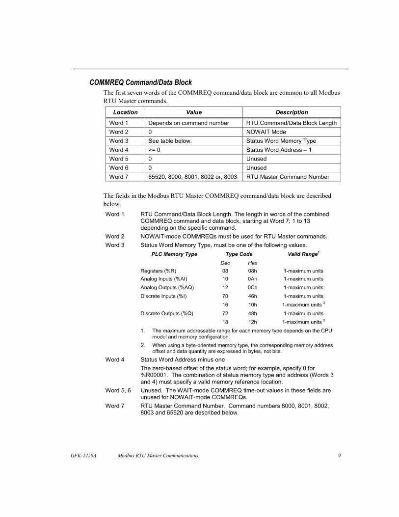
COMMREQ Command/Data BlockThe first seven words of the COMMREQ command/data block are common to all ModbusRTU Master commands.
Location Value Description
Word 1 Depends on command number RTU Command/Data Block LengthWord 2 0 NOWAIT ModeWord 3 See table below. Status Word Memory TypeWord 4 >= 0 Status Word Address – 1Word 5 0 UnusedWord 6 0 UnusedWord 7 65520, 8000, 8001, 8002 or, 8003 RTU Master Command Number
The fields in the Modbus RTU Master COMMREQ command/data block are describedbelow.Word 1 RTU Command/Data Block Length. The length in words of the combined
COMMREQ command and data block, starting at Word 7; 1 to 13depending on the specific command.
Word 2 NOWAIT-mode COMMREQs must be used for RTU Master commands.Status Word Memory Type, must be one of the following values.
Type CodePLC Memory TypeDec Hex
Valid Range1
Word 3
Registers (%R) 08 08h 1-maximum unitsAnalog Inputs (%AI) 10 0Ah 1-maximum unitsAnalog Outputs (%AQ) 12 0Ch 1-maximum unitsDiscrete Inputs (%I) 70 46h 1-maximum units
16 10h 1-maximum units 2
Discrete Outputs (%Q) 72 48h 1-maximum units18 12h 1-maximum units 2
1. The maximum addressable range for each memory type depends on the CPUmodel and memory configuration.
2. When using a byte-oriented memory type, the corresponding memory addressoffset and data quantity are expressed in bytes, not bits.
Word 4 Status Word Address minus oneThe zero-based offset of the status word; for example, specify 0 for%R00001. The combination of status memory type and address (Words 3and 4) must specify a valid memory reference location.
Word 5, 6 Unused. The WAIT-mode COMMREQ time-out values in these fields areunused for NOWAIT-mode COMMREQs.
Word 7 RTU Master Command Number. Command numbers 8000, 8001, 8002,8003 and 65520 are described below.

10 Modbus RTU Master Communications - December 2002
Modbus RTU Master Status Word FormatAll Modbus RTU Master commands return a two-byte status value to the status wordlocation specified in the COMMREQ command/data block. The low-order or leastsignificant byte (LSB) contains a completion status or major error code, and the high-order or most significant byte (MSB) may contain a minor error code. When a commandcompletes successfully, the completion status is one and the minor error code value iszero; consequently the value of the entire status word is one.
Major and minor error codes and their descriptions are listed in the Error Codes section ofthis document for each Modbus RTU Master command.
Queue Limitation for Modbus RTU Master COMMREQsA COMMREQ is pending between the time the COMMREQ function block executes inthe PLC application and the time the port writes to the COMMREQ status location. Eachport that is configured for Modbus RTU Master will accept no more than 2 pendingCOMMREQs at one time.
If the maximum number of COMMREQs is pending and the PLC application attempts tosend another to the port, a fault will be posted to the PLC fault table:
Comm req not processed due to PLC memory limitations.
Note that when two or more COMMREQs are pending at once, each one needs a uniquestatus location.
GFK-2220A Modbus RTU Master Communications 11
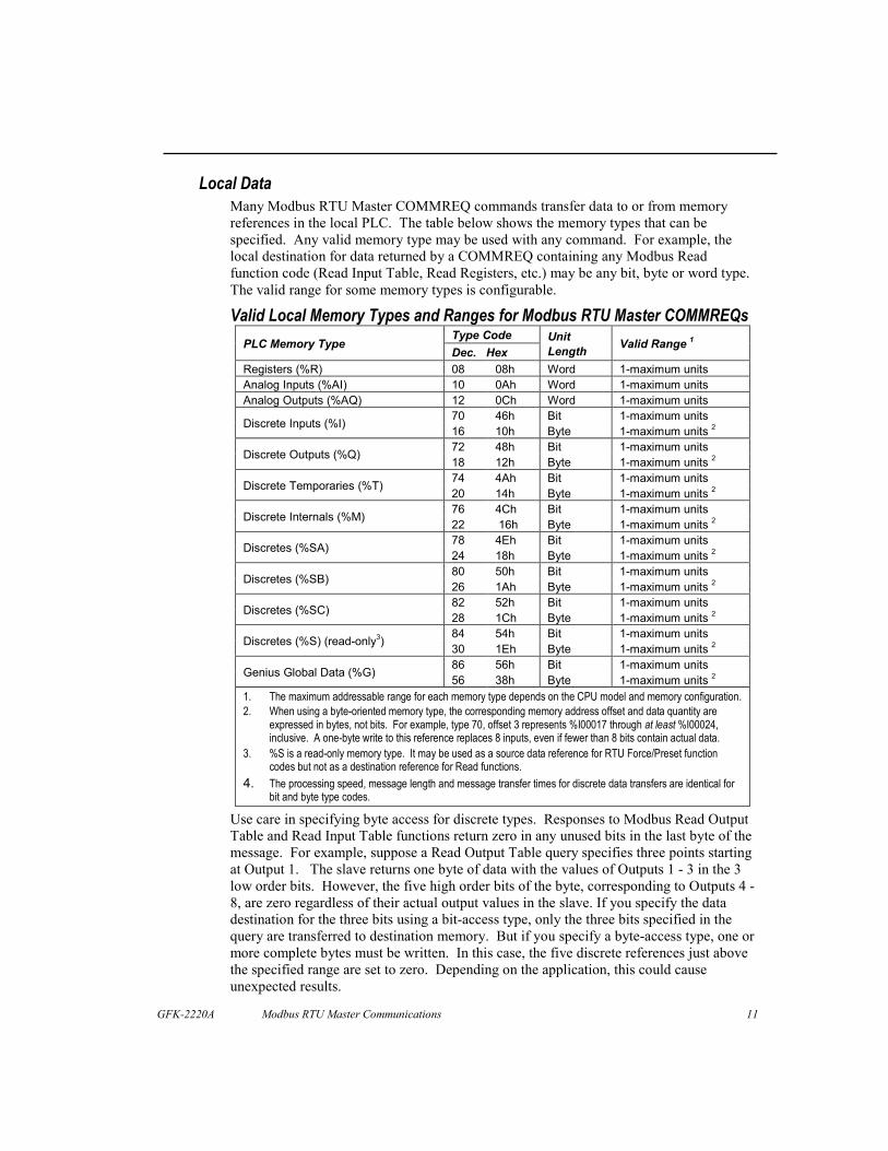
Local DataMany Modbus RTU Master COMMREQ commands transfer data to or from memoryreferences in the local PLC. The table below shows the memory types that can bespecified. Any valid memory type may be used with any command. For example, thelocal destination for data returned by a COMMREQ containing any Modbus Readfunction code (Read Input Table, Read Registers, etc.) may be any bit, byte or word type.The valid range for some memory types is configurable.
Valid Local Memory Types and Ranges for Modbus RTU Master COMMREQsType Code
PLC Memory TypeDec. Hex
UnitLength Valid Range 1
Registers (%R) 08 08h Word 1-maximum unitsAnalog Inputs (%AI) 10 0Ah Word 1-maximum unitsAnalog Outputs (%AQ) 12 0Ch Word 1-maximum units
70 46h Bit 1-maximum unitsDiscrete Inputs (%I) 16 10h Byte 1-maximum units 2
72 48h Bit 1-maximum unitsDiscrete Outputs (%Q) 18 12h Byte 1-maximum units 2
74 4Ah Bit 1-maximum unitsDiscrete Temporaries (%T) 20 14h Byte 1-maximum units 2
76 4Ch Bit 1-maximum unitsDiscrete Internals (%M) 22 16h Byte 1-maximum units 2
78 4Eh Bit 1-maximum unitsDiscretes (%SA) 24 18h Byte 1-maximum units 2
80 50h Bit 1-maximum unitsDiscretes (%SB) 26 1Ah Byte 1-maximum units 2
82 52h Bit 1-maximum unitsDiscretes (%SC) 28 1Ch Byte 1-maximum units 2
84 54h Bit 1-maximum unitsDiscretes (%S) (read-only3) 30 1Eh Byte 1-maximum units 2
86 56h Bit 1-maximum unitsGenius Global Data (%G) 56 38h Byte 1-maximum units 2
1. The maximum addressable range for each memory type depends on the CPU model and memory configuration.2. When using a byte-oriented memory type, the corresponding memory address offset and data quantity are
expressed in bytes, not bits. For example, type 70, offset 3 represents %I00017 through at least %I00024,inclusive. A one-byte write to this reference replaces 8 inputs, even if fewer than 8 bits contain actual data.
3. %S is a read-only memory type. It may be used as a source data reference for RTU Force/Preset functioncodes but not as a destination reference for Read functions.
4. The processing speed, message length and message transfer times for discrete data transfers are identical forbit and byte type codes.
Use care in specifying byte access for discrete types. Responses to Modbus Read OutputTable and Read Input Table functions return zero in any unused bits in the last byte of themessage. For example, suppose a Read Output Table query specifies three points startingat Output 1. The slave returns one byte of data with the values of Outputs 1 - 3 in the 3low order bits. However, the five high order bits of the byte, corresponding to Outputs 4 -8, are zero regardless of their actual output values in the slave. If you specify the datadestination for the three bits using a bit-access type, only the three bits specified in thequery are transferred to destination memory. But if you specify a byte-access type, one ormore complete bytes must be written. In this case, the five discrete references just abovethe specified range are set to zero. Depending on the application, this could causeunexpected results.

12 Modbus RTU Master Communications - December 2002
Modbus RTU Master Diagnostic Status WordsThe Modbus RTU Master protocol maintains certain diagnostic status data as a table ofwords. This data can be useful during application development as well as during normaloperation.
Commands are provided to read all or part of the Diagnostic Status Words table and toclear the table. The table is also cleared when the RTU Master port is initialized or re-initialized by a Serial Port Setup COMMREQ.
Format of Diagnostic Status Words
Location Description
Word 1 RTU error status word: the LSB and MSB contain the Major and Minorerror code values, respectively, from the most recent RTU MasterCOMMREQ error, internal error, or RTU exception response. Containszero if no errors have occurred.
Word 2 Number of RTU Master COMMREQs received from the PLC CPU.Word 3 Number of RTU queries sent from the serial port.Word 4 Number of RTU queries that were not transmitted before the time-out
expired.Word 5 Number of RTU normal responses received on the serial port.Word 6 Number of RTU exception (error) responses received on the serial port.Word 7 Number of RTU response time-outs.Word 8 Number of RTU responses with serial port errors.Word 9 Number of RTU responses with invalid length.Word 10 Number of RTU responses with invalid CRC.Word 11 Number of RTU responses with invalid device address.Word 12 Number of RTU responses with invalid function code.Word 13 Number of RTU Loopback/Maintenance responses with invalid data.Word 14 Number of RTU valid responses detected after response time-outWord 15 – 18 Last RTU query: the first 8 bytes of the most recent RTU query sent
from the serial port. For queries shorter than 8 bytes, the extra bytesare undefined. Contains zeros if no queries have been sent.
Word 19 – 22 Last RTU response: the first 8 bytes of the most recent RTU responsereceived on the serial port. For responses shorter than 8 bytes, theextra bytes are undefined. Contains zeros if no responses have beenreceived.
Word 23 – 38 Error COMMREQ data block: a copy of the command/data block of themost recent COMMREQ that produced an error. Contains zeros if noCOMMREQ errors have occurred. If the command/data block is longerthan 16 words, only the first 16 words are copied.

GFK-2220A Modbus RTU Master Communications 13
Modbus RTU Master CommandsThe following pages describe the Modbus RTU Master commands that can be used.
Initialize RTU Master Port: 65520 (FFF0)Local command
The standard Serial Port Setup COMMREQ may be used to configure the port for ModbusRTU Master operation using configuration values specified in the data block. It may alsobe used to modify configuration values during Modbus RTU Master operation. Note thatthe usage of words 19 and 20 is different from Modbus RTU Slave.
When the CPU hardware configuration assigns a different protocol to the target port andthis COMMREQ is used to start Modbus RTU Master, the application must not issueadditional Modbus RTU Master COMMREQs until this one completes successfully. Theapplication must monitor the value in the COMMREQ status location do determinesuccessful completion.
When this COMMREQ is used to re-initialize Modbus RTU Master during operation, theDiagnostic Status Words are cleared.

14 Modbus RTU Master Communications - December 2002
Command Block FormatLocation Value Description
Word 1 16 for Modbus RTU Master Port Setup Command/Data Block Length inwords (includes Words 7 – 22, inclusive)
Word 2 0 NOWAIT Mode (required)Word 3 See table on page 9. Status Word Memory TypeWord 4 >= 0 See page 9. Status Word Address – 1.Word 5 0 (Ignored) WAIT Mode time-out values are unusedWord 6 0 (Ignored) WAIT Mode time-out values are unusedWord 7 65520 Command – Port SetupWord 8 3 Protocol – Modbus RTUWord 9 1 Mode – Master (New for Modbus RTU)Word 10 2 = 1200, 3 = 2400, 4 = 4800,
5 = 9600, 6 = 19200, 7 = 38400,8 = 57600, 9 = 115200
Data Rate
Word 11 0 = NONE, 1 = ODD, 2 = EVEN ParityWord 12 0 = HARDWARE, 1 = NONE Flow ControlWord 13 0 (Ignored) SNP Turnaround DelayWord 14 0 = LONG (8 Seconds),
1 = MEDIUM (2 Seconds),2 = STANDARD (500 Milliseconds),3 = SHORT (200 Milliseconds)
Response message time-out– the specifiedvalue must be greater than the sum of thelongest receive-to-transmit delay for all slavesplus the longest response messagetransmission time at the current data rate.
Word 15 1 (Ignored) Bits per Character – Modbus RTU requires 8bits.
Word 16 0 (Ignored) Stop Bits – Modbus RTU forces 1 stop bit.Word 17 0 (Ignored) Port Interface – not software configurable in
VersaMax or IC693CPU363; Port 1 = RS-232,Port 2 = RS-485
Word 18 0 (Ignored) Half-Duplex Mode – Modbus RTU Master andSlave always disable the port receiver whiletransmitting, effectively operating in 2-wiremode.
Word 19 0 – 65,535 (0 to 6.5535 seconds)0 = Default
Character-gap time-out in 100-microsecondunits. See the description below.
Word 20 (0 to 6.5535 seconds)0 = Default (See description below.)
RTS Drop Delay in 100 microsecond units.
Words21 – 22
0 (Ignored) The required minimum Port Setupcommand/data length includes these words.However, the Modbus RTU Master ignorestheir values.
Description of Command WordsWord 7 - Port Setup: Command Number 65520 (0FFF0) hex
Word 8 - Protocol: 3 = Modbus RTU
Word 9 - Mode: 1 = Modbus RTU Master

GFK-2220A Modbus RTU Master Communications 15
Word 10 - Data Rate: The highest valid rate depends on the specific Modbus RTUMaster device. For example, 19,200 bits/second (bps) is the highest data rate supported byModbus RTU Master and Slave on IC693CPU363, IC200CPU001 and IC200CPU002.IC200CPU005 and IC200CPUE05 currently support 57,600 bps.
Word 11 - Parity: Note that when parity = ODD or EVEN, the character length used byModbus RTU Master is 11 bits: one start bit, 8 data bits, one parity bit and one stop bit.There is no parity bit when parity = NONE, and the character length is 10 bits. TheModbus RTU standard recommends 11 bits in all cases.
Word 12 – Flow Control: 2 = SOFTWARE is invalid; a Parameter Error (020Ch) isreturned to the status location specified in the Initialize Port COMMREQ.
When 0 = HARDWARE is specified, the port asserts RTS and waits for CTS to becomeactive before transmitting. If CTS does not become active within 2 seconds, a time-outerror code is returned to the status location specified in the Send RTU Query COMMREQ.
If CTS becomes active and then is de-asserted while the port is transmitting, up to 5milliseconds may elapse before transmission stops. The maximum number of characterstransmitted after CTS is de-asserted is proportional to the data rate. These values are inaddition to the character that is being transmitted at the time CTS is de-asserted.
Data Rate Max. Characters afterCTS is De-asserted
Data Rate Max. Characters afterCTS is De-asserted
1200240048009600
1235
192003840057600115200
10202958
Word 13 – SNP Turnaround Delay: This value is ignored. However, the specified valuemust be valid (0 - 255).
Word 14 – Response message time-out: When a Send RTU Query COMMREQ specifiesa broadcast query, COMMREQ_OK is returned to the COMMREQ status location whenthis time-out expires.
When a Send RTU Query COMMREQ specifies a non-broadcast query, aRESPONSE_TIMEOUT error code is returned to the COMMREQ status location whenthis time-out expires before a complete response is received.
Modbus RTU requires a time-out in all cases. Accordingly, the numeric values 2(STANDARD) and 3 (SHORT) are defined differently here than for other protocols.
The STANDARD timeout (500 milliseconds) is recommended by the Modbus RTUstandard.
The time-out begins after the port has transmitted the last character of the query and stopswhen the character-gap time-out (Word 19) expires after the last response character isreceived. If the response time-out expires before the end of the character-gap time-out,the port is checked for a response message. If one is detected (for example, because theresponse time-out expired after the response was received but before the character-gaptime-out expired), the response is processed normally after the gap timeout expires. If no

16 Modbus RTU Master Communications - December 2002
valid response is detected, a time-out error code is returned to the COMMREQ statuslocation.
Word 15 – Bits per Character: The Bits Per Character setting is forced to 8 becauseModbus RTU requires 8 bits per character. However, the specified value must be valid (0or 1).
Word 16 – Stop Bits: The Stop Bits setting is forced to 1 stop bit for compatibility withGE Fanuc Automation RTU Slave implementations. However, the specified value mustbe valid (0 or 1).
Word 17 – Port Interface: The Port Interface is not software-configurable in VersaMaxCPU or IC693CPU363 modules: Port 1 is RS-232 only, and Port 2 is RS-485 only.However, the specified value must be valid (0 or 1).
Word 18 – Half-Duplex Mode: Modbus RTU Master and Slave always operate in 2-wiremode. However, the specified value must be valid (0, 1 or 2).
Just before transmitting, the port disables the receiver. On RS-485 ports the Send Dataand RTS line drivers switch from high-impedance state to active state.
One character time (or the time value specified in Word 20, if any) after the last messagecharacter is transmitted, the port turns off RTS and enables the receiver. On RS-485 portsthe Send Data and RTS line drivers switch to their high-impedance state.
Word 19 – Character-gap time-out between messages in 100-microsecond units: This isthe time interval that defines the end of each received response message. It is measuredfrom the end of the last received character. RTS is off and the transmitter is silent duringthis interval. If a new query is ready for transmission, RTS is asserted no earlier than theend of this interval.
On RS-485 ports, the Send Data and RTS signals remain in the high-impedance state untilat least the end of this interval.
Zero specifies the default, defined as 3.5 character times at the specified data rate,assuming 11 bits per character.
Data Rate Default (100 µ-sec. units) Data Rate Default (100 µ-sec. units)1200240048009600
3221618040
192003840057600115200
211073
Any specified value smaller than the default is replaced by the default.
This value also performs the function of the Modbus RTU slave receive-to-transmit delay.If the required delay is greater than the default value at the current data rate, increase thespecified value to required delay in 100-microsecond units. If the required delay is lessthan the default at the current data rate, no additional delay is necessary.
Word 20 – RTS Drop Delay in 100 microsecond units: This is the time from the end ofthe last transmitted character to the time when RTS is turned off (dropped).

GFK-2220A Modbus RTU Master Communications 17
The receiver is disabled during transmission and remains disabled during the RTS dropdelay time. If the specified delay is longer than the Modbus RTU slave’s silent intervalbetween the query and its response, the master will ignore all or part of the response.
Zero specifies the default, defined as one character time at the specified data rate,assuming 11 bits per character.
Data Rate Default (100 µ-sec. units) Data Rate Default (100 µ-sec. units)1200240048009600
92462312
192003840057600115200
6321
Any specified value smaller than the default is replaced by the default.
Note that RTS Drop Delay is specified in 10 millisecond units for Modbus RTU slave.
Words 21 – 22: The required minimum Serial Port Setup command/data length includesthese words. However, their values are ignored for Modbus RTU Master.
Error CodesThis command returns different error codes depending on the protocol that is active whenit is sent. When SNP Slave or Serial I/O is active, error code 020Ch is returned to theCOMMREQ status location if any of the data block values is invalid. For example:
A value specifying the protocol, data rate, parity, flow control, etc. is outside its validrange.
Modbus RTU Master Mode is not supported on the specified port. The Master modevalue (Word 9 = 1) is outside the valid range in this case.
When RTU Master is already active, error code 0503h has the same meaning.
Differences Between Modbus RTU Master and Slave Formats:Modbus RTU slave ignores the response message time-out value in Word 14.
For Modbus RTU slave, Word 19 contains the slave device address, and Words 20 – 22are unused. For Modbus RTU master, Word 19 contains the character-gap time-out, word20 contains the RTS drop delay, and words 21 – 22 are unused.
The Modbus RTU slave RTS drop delay in Word 24 is specified in 10 millisecond units.The Modbus RTU master RTS drop delay in Word 20 is specified in 100 microsecondunits.
In Modbus RTU master, the function of the slave receive-to-transmit delay (Word 23) isincluded in the character-gap time-out in Word 19.
18 Modbus RTU Master Communications - December 2002
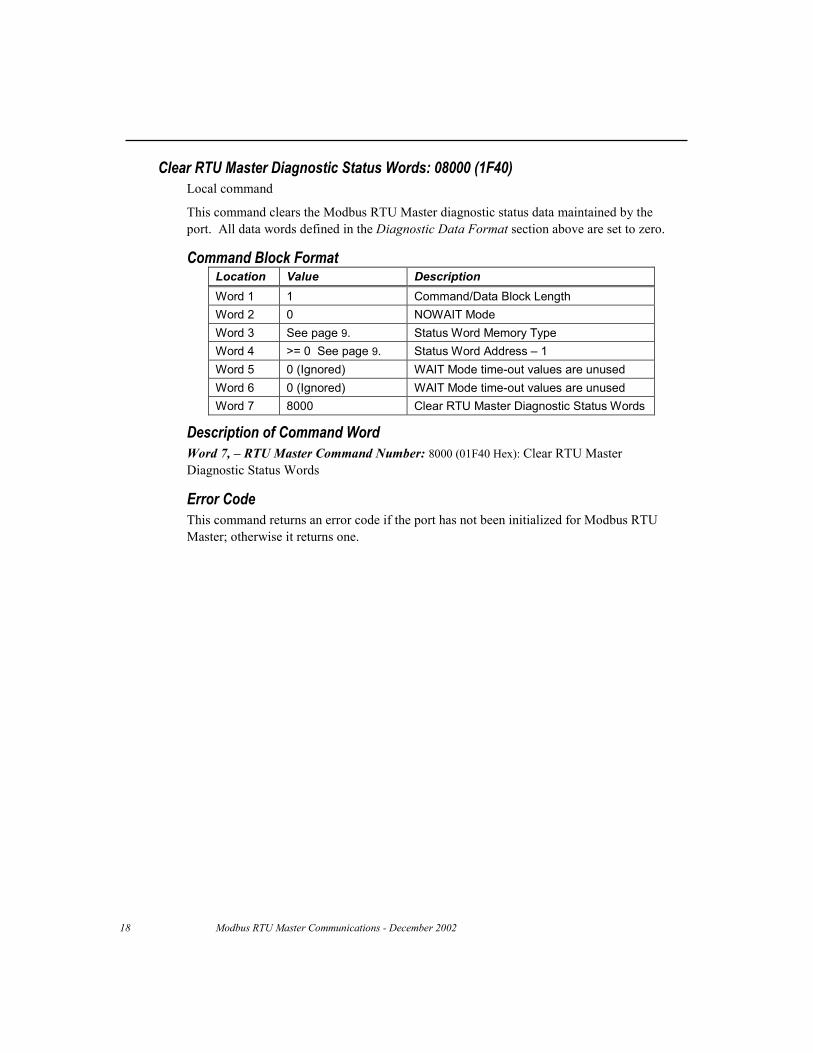
Clear RTU Master Diagnostic Status Words: 08000 (1F40)Local command
This command clears the Modbus RTU Master diagnostic status data maintained by theport. All data words defined in the Diagnostic Data Format section above are set to zero.
Command Block FormatLocation Value DescriptionWord 1 1 Command/Data Block LengthWord 2 0 NOWAIT ModeWord 3 See page 9. Status Word Memory TypeWord 4 >= 0 See page 9. Status Word Address – 1Word 5 0 (Ignored) WAIT Mode time-out values are unusedWord 6 0 (Ignored) WAIT Mode time-out values are unusedWord 7 8000 Clear RTU Master Diagnostic Status Words
Description of Command WordWord 7, – RTU Master Command Number: 8000 (01F40 Hex): Clear RTU MasterDiagnostic Status Words
Error CodeThis command returns an error code if the port has not been initialized for Modbus RTUMaster; otherwise it returns one.

GFK-2220A Modbus RTU Master Communications 19
Read RTU Master Diagnostic Status Words: 08001 (1F41)Local command
This command copies the Modbus RTU Master diagnostic status data maintained by theport to a reference address specified in the command block. The data is useful fordebugging Modbus RTU master applications during development and for monitoring theRTU network during normal operation.
Command Block FormatLocation Value DescriptionWord 1 5 Command/Data Block LengthWord 2 0 NOWAIT ModeWord 3 See page 9. Status Word Memory TypeWord 4 >= 0 See page 9. Status Word Address – 1Word 5 0 (Ignored) WAIT Mode time-out values are unusedWord 6 0 (Ignored) WAIT Mode time-out values are unusedWord 7 8001 Read RTU Master Diagnostic Status
WordsWord 8 1 – 38 First diagnostic status word to readWord 9 1 - (39 – Word 8) Number of diagnostic status words to readWord 10 See page 11. Data Memory TypeWord 11 >= 1 Data Address
Description of the Command WordsWord 7 – RTU Master Command Number: 8001 (01F41 Hex): Read RTU MasterDiagnostic Status Words
Word 8 – First Diagnostic Status Word to Read: The word number in the DiagnosticStatus data where the data that will be read begins. To read all of the data, specify 1.
Word 9 – Number of Diagnostic Status Words to Read: The total count of DiagnosticStatus data words that will be read. To read one word, specify 1. To read all of the data,specify 38.The total of the values in Word 8 and Word 9 must not be greater than the size of theDiagnostic Status Words in words plus one (39).
Word 10 – Data Memory Type: The memory type where diagnostic status data will bereturned; see Page 11 for valid types.
Word 11 – Data Address: The one-based offset of the first word where diagnostic statusdata will be returned; for example, specify 101 for %R00101. The size and format ofModbus RTU Master diagnostic status data are specified in Table 3.
Error CodesThis command returns an error code if the port has not been initialized for Modbus RTUMaster OR the data memory type and address are invalid; otherwise it returns one.

20 Modbus RTU Master Communications - December 2002
Send RTU Read/Force/Preset Query: 08002 (1F42)Remote commandThis command sends a Modbus RTU Master Read, Force, Preset, or Report Device Typequery message as specified in the command/data block.
Command Block FormatLocation Value DescriptionWord 1 7 Command/Data Block LengthWord 2 0 NOWAIT ModeWord 3 See page 9. Status Word Memory TypeWord 4 >= 0 See page 9. Status Word Address – 1Word 5 0 (Ignored) WAIT Mode time-out values are unusedWord 6 0 (Ignored) WAIT Mode time-out values are unusedWord 7 8002 Send RTU Master Read/Force/Preset QueryWord 8 0 - 247 Target RTU Device AddressWord 9 See table below. RTU Function CodeWord 10 See below. RTU Data Address/Start AddressWord 11 See below. RTU Number of Points/RegistersWord 12 See below. Data Memory Type of source (for Force,/Preset
queries) or destination (for Read queries)Word 13 >= 1 Data Address of source (for Force,/Preset
queries) or destination (for Read queries)
Description of the Command WordsWord 7 – RTU Master Command Number: 8002 (01F42 Hex): Send RTURead/Force/Preset Query
Word 8 – Target RTU Device Address: This is the 8-bit address of the Modbus RTUslave to which the query is addressed, using Modbus addressing. Address zero is thebroadcast address. Any query sent to the broadcast address should not result in aresponse. Valid device addresses are in the range 1 through 247 inclusive.Schneider/Modicon has reserved the values 248 to 255.Word 9 – RTU Function Code: This is the 8-bit function code for the query. Thefollowing function codes are supported; all others are invalid.
Function Code ValueDec. Hex.
Function Name SlaveReference Type
Valid as BroadcastQuery?
1 01 Read Output Table %Q No2 02 Read Input Table %I No3 03 Read Registers %R No4 04 Read Analog Inputs %AI No5 05 Force Single Output %Q Yes6 06 Preset Single Register %R Yes7 07 Read Exception Status %Q No15 0F Force Multiple Outputs %Q Yes16 10 Preset Multiple Registers %R Yes17 11 Report Device Type N/A No67 43 Read Scratch Pad
MemoryN/A No

GFK-2220A Modbus RTU Master Communications 21
Word 10 – RTU Data Address/Start Address: The one-based offset into the targetreference data type on the slave that specifies:
� The data location for the Force Single Output and Preset Single Register functioncodes;
� The start of the data range for Read Output Table, Read Input Table, Read Registers,Read Analog Inputs, Force Multiple Outputs and Preset Multiple Registers functioncodes; and
� The starting byte number for the Read Scratch Pad Memory function code.
For example, specify 101 for either %R00101 in a GE Fanuc PLC or Holding Register4101/40101 in a Schneider/Modicon PLC.
This word is ignored for the Read Exception Status and Report Device Type functioncodes.
Word 11 – RTU Number of Points/Registers/Byte: The number of 1-bit points (ReadOutput Table, Read Input Table, Force Multiple Outputs) or 16-bit registers (ReadRegisters, Read Analog Inputs, Preset Multiple Registers) that will be sent to the slave in aForce/Preset Multiple query or requested from the slave in a Read query, or the number ofbytes that will be requested in a Read Scratch Pad Memory request.
This word is ignored for the Force Single Output, Preset Single Register,Read Exception Status and Report Device Type function codes.
Note that the Byte Count field in Force/Preset Multiple queries will be calculated fromRTU Number of Points/Registers according to the size of the target reference typeassociated with the RTU Function Code.
Word 12 –Data Memory Type: This is the memory reference data type in the local PLCfor the source of transmitted data in Force/Preset queries or the destination where responsedata is copied for Read queries. Page 11 of this document specifies the valid types.
Word 13 – Data Address: This is the one-based offset in the local PLC of the source dataaddress for Force/Preset queries or the destination data address for Read queries. Forexample, specify 101 for %R00101.
The entire range of data references defined by the Data Memory Type, Data Address, andNumber of Points/Registers/Bytes must be valid in the local PLC. For example, if thelocal PLC is configured with a Register Memory size of 2048 words, and the Number ofRegisters in a Read Registers query is 120, then the largest valid Data Address is%R01929 (2048 – 120 + 1).

22 Modbus RTU Master Communications - December 2002
Send RTU Diagnostic Query: 08003 (1F43)Remote command
This command sends one of the following Modbus RTU Master queries as specified in thecommand/data block: Loopback/Maintenance
Command Block FormatLocation Value DescriptionWord 1 5 Command/Data Block LengthWord 2 0 NOWAIT ModeWord 3 See page 9. Status Word Memory TypeWord 4 >= 0 See page 9. Status Word Address – 1Word 5 0 (Ignored) WAIT Mode time-out values are unusedWord 6 0 (Ignored) WAIT Mode time-out values are unusedWord 7 8003 Send RTU Master Diagnostic QueryWord 8 0 - 247 Target RTU Device AddressWord 9 See below. RTU Function CodeWord 10 See below. Loopback/Maintenance Diagnostic CodeWord 11 See below. Loopback/Maintenance Data
Description of the Command WordsWord 7 – RTU Master Command Number: 8003 (01F43 Hex): Send RTU DiagnosticQuery
Word 8 – Target RTU Device Address: This is the 8-bit device address of the ModbusRTU slave device to which the RTU query is addressed, using the Modbus addressingscheme. Address zero is the broadcast address. Any query sent to the broadcast addressshould not result in a response.
Valid device addresses are in the range 1 through 247 inclusive. Schneider/Modicon hasreserved the values 248 to 255.
Word 9 – RTU Function Code: This is the 8-bit function code for the Modbus RTUQuery. The following function codes will be supported; all others are invalid.
Function CodeValue Function Name Valid as
Broadcast Query8 (08h) Loopback/Maintenance No/Yes

GFK-2220A Modbus RTU Master Communications 23
Word 10 – Loopback/Maintenance Diagnostic Code: The following diagnostic codes aresupported for Loopback/Maintenance queries; all others are invalid.
DiagnosticCode Value Description
Valid asBroadcast
Query0 Return Query Data – target slave should respond
by sending a duplicate of the query message.No
1 Initiate Communication Restart – target slave(s)disable Listen-only Mode (if enabled).
Yes
4 Force Listen-only Mode – target slave(s) enableListen-only Mode
Yes
Word 11 – Loopback/Maintenance Data: The following data values are required inLoopback/Maintenance queries; all others are invalid.
DiagnosticCode Value Loopback/Maintenance Data Value
0 Any 16-bit unsigned value: 0 - 65,535 (0 - 0FFFFh)1 Clear Communications Event Log: 65280 (FF00h)
Do not clear Event Log: 0 (0000h)4 0

24 Modbus RTU Master Communications - December 2002
Error Codes for RTU Master CommandsSymbolic and numeric values for major and minor error codes and their meanings areshown in the table below.
Major Error Code Minor Error Code StatusValue Description
COMMREQ_OK None 0001h The RTU Master COMMREQ command has succeeded.NOT_A_COMREQ 0103h A Message received from CPU is not a COMREQ.WAIT_COMREQ 0203h WAIT-mode COMREQs are not supported.UNSUPP_COMREQ_CMD 0303h The COMREQ Command is unsupported.COMREQ_LEN_INVALID 0403h The COMREQ data length is too small.PORT_DATA_INVALID 0503h Port Setup COMREQ data is invalid.DEV_ADDRESS_INVALID 0603h The RTU slave device is invalid.FUNC_CODE_UNSUPPORTED 0703h The RTU function code is not supported.FUNC_INVALID_FOR_BCAST 0803h The specified function code requires a response.DIAG_CODE_UNSUPPORTED 0903h The Diagnostic code is unsupported in Loopback/Maintenance queries.DATA_START_INVALID 0A03h The specified data starting location is invalid.DATA_QUANTITY_INVALID 0B03h The specified data quantity results in an invalid message length.DATA_MEM_TYPE_INVALID 0C03h The specified memory type for the data source/destination is invalid for
local PLC CPU.DATA_MEM_OFFSET_INVALID 0D03h The specified memory location for the data source/destination is invalid for
local PLC CPU.STATUS_MEM_TYPE_INVALID 0E03h The specified status memory type invalid for the local PLC CPU.STATUS_MEM_OFFSET_INVALID
0F03h The specified status memory location invalid for the local PLC CPU.
DSW_RANGE_INVALID 1003h The specified Diagnostic Status Words starting location or length is invalid.
PARAMETER_ERROR
BUF_ALLOC_ERROR 1103h An error occurred during an attempted system memory allocation.PARITY_ERROR 0104h Parity error detected, response discarded.FRAMING_ERROR 0204h Framing error detected, response discarded.OVERRUN_ERROR 0204h Over-run error detected, response discarded.SHORT_RSP_ERROR 0304h Incomplete response detected, response discarded.
PORT_ERROR
CRC_ERROR 0404h CRC error detected, response discarded.QUERY_XMIT_TIMEOUT 0105h HARDWARE flow control is in use, and CTS was not detected within the
specified time.TIMEOUT_ERROR
RESPONSE_TIMEOUT 0205h A response was not received within the specified time.STATUS_WORD_WRITE_ERR 0106h An error occurred while writing the COMREQ Status Word.DATA_WRITE_ERR 0206h An error occurred while writing to RTU Data Memory.
MEM_ERROR
DATA_READ_ERR 0306h An error occurred while reading from RTU Data Memory.INVALID_RESPONSE_CRC 0107h The response CRC-16 is incorrect.INVALID_RESPONSE_LENGTH 0207h The response length is incorrect.INVALID_RESPONSE_ADDR 0307h The response device address is incorrect.INVALID_RESPONSE_FUNC 0407h The response function code is incorrect.
RESPONSE_ERROR
INVALID_LOOPBACK_RESP 0507h A Loopback/Maintenance response data is incorrect.ILLEGAL_FUNCTlON 0108h The Modbus slave detected a function code it does not support.ILLEGAL_DATA_ADDRESS 0208h The Modbus slave detected a data address it does not support.ILLEGAL_DATA_VALUE 0308h The Modbus slave detected a data value that is not allowable.SLAVE_DEVlCE_FAILURE 0408h The Modbus slave encountered an unrecoverable error while attempting to
complete the requested function.ACKNOWLEDGE 0508hSLAVE_DEVlCE_BUSY 0608h
RCVD_EXCEPTION
NEGATlVE_ACKNOWLEDGE 0708h
This exception code does not apply to the functions supported by thisimplementation.
MEMORY_PARlTY_ERROR 0908h The slave detected a parity error in extended memory.

GFK-2220A Modbus RTU Master Communications 25
Example ApplicationThe following example illustrates the basic programming principles used by Modbus RTUMaster applications. The example is provided in ladder diagram (LD) logic. It isavailable from the GE Fanuc PLC Technical Support web site in versions forIC693CPU363 and VersaMax modular CPUs. Application folders for CIMPLICITYMachine Edition Logic Developer - PLC, VersaPro, and Logicmaster 90-30(IC693CPU363 only) are available.
The example provides RTU Master communications only. It can be used as a frameworkfor developing actual applications. Alternatively, the example program blocks can beimported into other application folders and modified as needed.
Each of the program blocks in the example is described below.

26 Modbus RTU Master Communications - December 2002
MAIN Block ExampleThe example main block, named _MAIN, simply calls each of the other program blocks inturn. RTUINIT sets up serial port 2 for Modbus RTU master operation. Once thatprocess completes, the normally-closed contact %T00003 opens, and RTUINIT is nevercalled again as long as the PLC remains in Run mode.
RTUSTAT periodically reads the RTU master diagnostic status word (DSW) data fromport 2. This data is useful during application development but has little utility once thesystem goes into operation.
RTU_SLV sends a sequence of RTU queries to specified RTU slave devices from port 2.When an RTU response is received or times out, the next query in the sequence is sentimmediately. When the last response in the sequence is received or times out, the firstquery is sent again.
RTU_TMR is similar to RTU_SLV. A timer is added that controls the minimum timeinterval between successive transmissions of the first query in the sequence.
_MAIN Program Block
At most two of the blocks that periodically issue COMMREQ commands to the sameRTU master serial port may be called. In the logic shown above, blocks RTUSTAT andRTU_TMR are always called, while RTU_SLV is never called. An alternative designcould call two blocks similar to RTU_SLV (or to RTU_TMR), one to send queries thatrequest input data from a group of slaves, and the other to send outputs to another group ofslaves.

GFK-2220A Modbus RTU Master Communications 27
RTUINIT ExampleBlock RTUINIT is called immediately after the PLC enters Run mode. In the logic shownbelow, the BLKMOV function blocks in ladder rungs 2 and 4 initialize the status data anddata block for the COMMREQ that will set up serial port 2 for RTU master operation.The port is initialized as follows:COMMREQ status value: ZeroCOMMREQ status location: %R01001Protocol: Modbus RTUMode: MasterData rate: 19,200 bits/Sec.Parity: EvenFlow control: NoneTurnaround delay: ZeroResponse message time-out: STANDARD (0.5 Sec.)Bits per Character: 8 (Not configurable)Stop Bits: 1 (Not configurable)Port Interface: Not configurable for CPU ports, Port 1: RS-232, Port 2: RS-485Half-Duplex Mode: 2-Wire (Not configurable)Character-gap time-out: DefaultRTS Drop Delay: Zero
RTUINIT Program Block, Part 1

28 Modbus RTU Master Communications - December 2002
The next part of the RTUINIT block includes a two-second timer that delays the port setupCOMMREQ. Temporary contact %T00001 is automatically cleared on first scan, and thetimer function block begins timing immediately. When it times out, it sets the on-transition contact %T00002 that resets the timer and also sets %T00001. The latterprevents the timer from running.
RTUINIT Program Block, Part 2

GFK-2220A Modbus RTU Master Communications 29
The serial port setup COMMREQ function block shown below is activated once on thePLC scan when the timer shown on the previous page expires. If a COMMREQ faultoccurs, %T00001 is reset so that the delay timer will start again.
A COMMREQ fault will occur when the combination of COMMREQ SYS ID and TASKvalues is invalid. Note that the correct SYS ID value for IC693CPU363 is 1 (rack zero,slot one), while the correct value for VersaMax modular CPUs is 0 (rack zero, slot zero).
A COMMREQ fault will also occur in VersaMax modular CPUs when an invalidreference location is specified for the COMMREQ status.
If no COMMREQ fault occurs, the EQ_INT function block waits for the value in theCOMMREQ status word at %R01001 to be set to 1 by the serial port and then sets%T00003, the contact that indicates initialization has completed successfully. TheRTUINIT block is not called after %T00003 has been set.
An error code value may also be returned to the COMMREQ status word location. Errorstatus values often occur during application development because of errors in the serialport configuration data for the COMMREQ. Once the configuration data is correct,however, the port should never return an error status. To facilitate error diagnosis, thestatus value is visible from the program editor at the IN1 input of the EQ_INT functionblock shown below. See the PARAMETER_ERROR section of the Error Codes table inthis document for information on error status values for this COMMREQ.
RTUINIT Program Block, Part 3

30 Modbus RTU Master Communications - December 2002
RTUSTAT ExampleBlock RTUSTAT is called from _MAIN to read the RTU master diagnostic status word(DSW) data. RTUSTAT periodically sends a COMMREQ to the RTU master serial port.
The logic shown below includes the BLKMOV function blocks that initialize theCOMMREQ data. The data specifies %R01031 as the COMMREQ status location andrequests all 38 of the status words, starting at the first word. The destination for the statusdata is %R00961 - %R00998.
RTUSTAT Program Block, Part 1
GFK-2220A Modbus RTU Master Communications 31
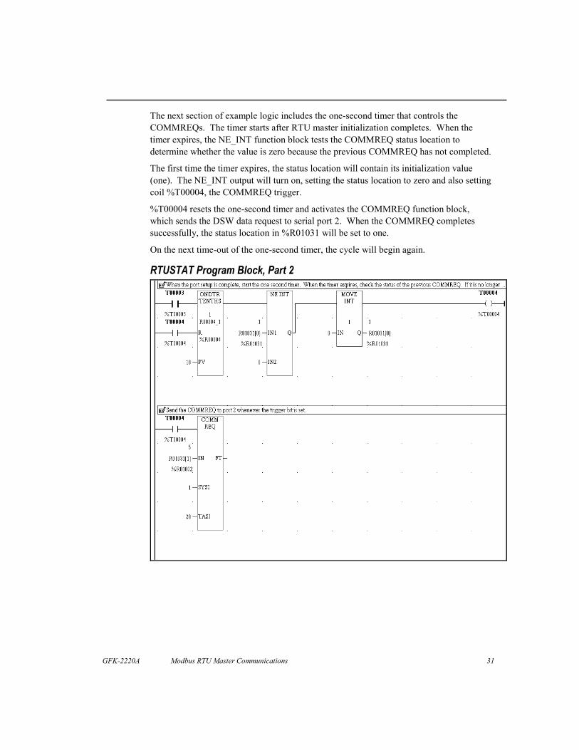
The next section of example logic includes the one-second timer that controls theCOMMREQs. The timer starts after RTU master initialization completes. When thetimer expires, the NE_INT function block tests the COMMREQ status location todetermine whether the value is zero because the previous COMMREQ has not completed.
The first time the timer expires, the status location will contain its initialization value(one). The NE_INT output will turn on, setting the status location to zero and also settingcoil %T00004, the COMMREQ trigger.
%T00004 resets the one-second timer and activates the COMMREQ function block,which sends the DSW data request to serial port 2. When the COMMREQ completessuccessfully, the status location in %R01031 will be set to one.
On the next time-out of the one-second timer, the cycle will begin again.
RTUSTAT Program Block, Part 2

32 Modbus RTU Master Communications - December 2002
RTU_SLV ExampleBlock RTU_SLV is called from _MAIN to send a sequence of Modbus RTU querymessages to RTU slave devices. Each query in the sequence is sent immediately when theprevious response arrives. When the last response of the sequence is received, thesequence repeats immediately. The example sequence contains five queries, but thesequence can be expanded to contain any number.
The logic shown below includes the BLKMOV function block that initializes the portionof the COMMREQ data that is common to all the queries in the sequence. The dataspecifies %R01051 as the COMMREQ status location.
RTU_SLV Program Block, Part 1
The NE_INT above instruction tests the value in the COMMREQ status location. When anon-zero value is detected, the status is set to zero and the COMMREQ trigger contact,%T00005, is turned on. The status location contains one after initialization on the firstscan, and after each query COMMREQ completes.

GFK-2220A Modbus RTU Master Communications 33
The logic below shows two BLKMOV instructions that initialize COMMREQ data for thefirst two queries in the sequence. Data for the first part of the sequence is not shown here.However, you can see it by opening the example program in an LD program editor such asCIMPLICITY Machine Edition Logic Developer – PLC.
All the queries share the same range of %R memory for COMMREQ status and data, buteach one has a separate block for data sent to or received from its target Modbus RTUslave.
The first BLKMOV instruction shown below is activated when the COMMREQ trigger,%T00005, and the enabling contact for the first query, %T00097, are both on. Thisinitializes the COMMREQ data block for the first query of the sequence. Similarly, thesecond query is initialized when %T00005 and %T00098 are both on. Contacts %T00099through %T00101 permit initialization of the third, fourth and fifth queries, respectively.
RTU_SLV Program Block, Part 2

34 Modbus RTU Master Communications - December 2002
The logic shown below sends each COMMREQ in sequence. The COMMREQinstruction is enabled by the trigger contact, %T00005. If a COMMREQ fault occurs, coil%T00081 is set. You can add logic that is enabled by a %T00081 contact to takewhatever action is appropriate for your application.
The SHFR_BIT instruction is used to step to the next query in the sequence each time aCOMMREQ is sent. All of the %T contacts are set to off when the PLC enters RUNmode, including the range %T00097 through %T00101 used by SHFR_BIT. The firstrung of RTU_SLV (shown on page 32) switches %T00097 on during the first logic scan.The SHFR_BIT instruction shifts this one bit to the next higher bit location each time%T00005 fires. When the one bit has been shifted the number of times specified by theSHFR_BIT length parameter, it returns to %T00097, and the sequence repeats.
The sequence can be made arbitrarily long by changing the SHFR_BIT length parameter.One additional BLKMOV instruction (similar to those in the previous section of logic)will be required for each added sequence step.
RTU_SLV Program Block, Part 3

GFK-2220A Modbus RTU Master Communications 35
This example RTU_SLV block does not check the COMMREQ status for errors.Additional logic, not shown here, can check the COMMREQ status location for errorvalues. Here is a suggested design outline that distinguishes programming errors fromnetwork errors.
1. Mask the minor error code (most significant byte) using an AND_WORD instructionwith the COMMREQ status word and the constant 00FF hexadecimal (16#00FF) asinputs. The result contains only the major error code. Specify an unused register asthe output.
2. Test the major error code for the decimal value 3 (COMMREQ parameter error) usingan EQ_INT instruction. This major error is caused by a programming error or anincompatibility between a COMMREQ parameter and the configured memory rangesof the PLC. It must be corrected in the application program or PLC hardwareconfiguration.
3. All other major errors are caused by conditions that the application may need to detectand handle while running – for example, temporary noisy network conditions, loss ofpower on a Modbus RTU slave, slave hardware configuration changes, etc. Notehowever, that major error code 8 indicates that a Modbus RTU response contained anexception. Some of these exceptions can be caused by errors in the query dataspecified in the COMMREQ data block.
RTU_TMR ExampleBlock RTU_TMR is similar to RTU_SLV and is not shown here. It adds an on-delaytimer to control the minimum time between the start of successive sequences of queriesand responses. The timer adds a state (one bit) at the start of the SHFR_BIT sequence toreset and start the timer. Another state is added at the end of the sequence to wait until thetimer reaches its programmed time-out value. After the time-out, the sequence beginsagain.