mobile network evolution gsm and · pdf filemobile network evolution gsm and umts u gsm ......
TRANSCRIPT

Integrated Communication Systems Group
Ilmenau University of Technology
Mobile Network Evolution
GSM and UMTSu GSM
u Cell layoutu Radio Accessu Architectureu Call setupu Mobility managementu Security
u GPRSu Architectureu Protocolsu QoS
u EDGEu Architectureu Modulation & coding
u UMTSu Architectureu Packet handlingu Resource management and
QoSu LTE
u Features and requirementsu Architectureu Packet handling and
resource managementu References
2
Integrated Communication Systems Group
Advanced Mobile Communication Networks
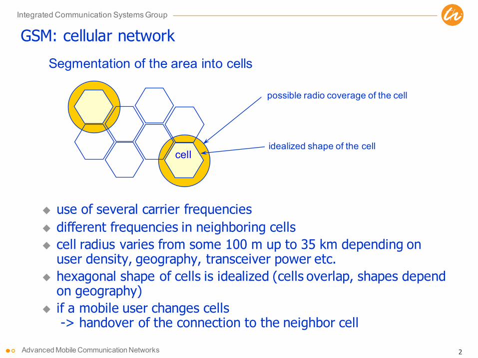
possible radio coverage of the cell
idealized shape of the cellcell
Segmentation of the area into cells
GSM: cellular network
u use of several carrier frequenciesu different frequencies in neighboring cellsu cell radius varies from some 100 m up to 35 km depending on
user density, geography, transceiver power etc.u hexagonal shape of cells is idealized (cells overlap, shapes depend
on geography)u if a mobile user changes cells
-> handover of the connection to the neighbor cell

3
Integrated Communication Systems Group
Advanced Mobile Communication Networks
Cellular systems: Frequency planning IFrequency reuse only beyond a certain distance between base stationsTypical (hexagon) model:
reuse-3 cluster: reuse-7 cluster:
Other regular pattern: reuse-19
è Frequency reuse pattern determines the experienced SIR
Fixed frequency assignment:u certain frequencies are assigned to a certain cellu problem: different traffic load in different cells
Frequency Hopping:u Improves quality for slow moving or stationary users (frequency diversity)u Reduces impact of intercell interference by statistical averaging
f4f5
f1f3
f2
f6
f7
f4f5
f1f3
f2
f6
f7
f4f5
f1f3
f2
f6
f7f2
f1f3
f2
f1f3
f2
f1f3

4
Integrated Communication Systems Group
Advanced Mobile Communication Networks
GSM: Air InterfaceFDMA (Frequency Division Multiple Access) / FDD (Frequency Division Duplex)
123124. . .
890 MHz 915 MHz
123124. . .
935 MHz 960 MHz
200 kHz
Uplink Downlink
frequency
TDMA (Time Division Multiple Access)
time
Downlink
87654321
4,615 ms = 1250 bit
Uplink
87654321

5
Integrated Communication Systems Group
Advanced Mobile Communication Networks
Framing Modulation(GMSK)
GSM: Voice Coding
Voice coding Channelcoding Framing Modulation
(GMSK)
114 bit/slot114 + 42 bit
Guard (8.25 bits): avoid overlap with other time slots (different time offset of neighboring slot)Training sequence: select the best radio path in the receiver and train equalizerTail: needed to enhance receiver performanceFlag S: indication for user data or control data
1 2 3 4 5 6 7 8GSM TDMA frame
GSM time-slot (normal burst)
4.615 ms
546.5 µs577 µs
tail user data TrainingSguardspace S user data tail
guardspace
3 bits 57 bits 26 bits 57 bits1 1 3

6
Integrated Communication Systems Group
Advanced Mobile Communication Networks
GSM Architecture
GSMRAN
Base stationBase stationcontroller
Base station
Base station
MSC
ISDN
GSM Core (Circuit switched)
HLRAuCEIR
GMSC
TransmissionATM based
GSM

7
Integrated Communication Systems Group
Advanced Mobile Communication Networks
GSM system: Network elementsGSM is a PLMN (Public Land Mobile Network)u several providers setup mobile networks following the GSM standard
within each country
GSM Elements:u MS (mobile station)u Radio Access Network (Base station subsystem - BSS): covers
all radio aspectsu BTS (base transeiver station)u BSC (base station controller)
u Core Network: call forwarding, handover, switchingu MSC (mobile services switching center)u LR (location register): HLR and VLRu OMC (operation and maintenance centre)u AuC (authentication centre)u EIR (equipment identity register)

8
Integrated Communication Systems Group
Advanced Mobile Communication Networks
Mobile Terminated Call (MTC)
PSTNcallingstation GMSC
HLR VLR
BSSBSSBSS
MSC
MS
1 2
3
4
5
6
7
8 9
10
11 12
1316
10 10
11 11 11
14 15
17
1: calling a GSM subscriber2: forwarding call to GMSC3: signal call setup to HLR4, 5: request MSRN from VLR6: forward responsible
MSC to GMSC7: forward call to
current MSC8, 9: get current status of MS10, 11: paging of MS12, 13: MS answers14, 15: security checks16, 17: set up connection

9
Integrated Communication Systems Group
Advanced Mobile Communication Networks
RA
RA
RA RA
RA
RA RA
RA
RA
LocationUpdate
LocationUpdate
LocationUpdate
LocationUpdate
LocationUpdate
Location Management / Mobility ManagementThe issue: Compromise between
u minimizing the area where to search for a mobile
u minimizing the number of location updates
Solution 1:Large paging area
Solution 2:Small paging area
PagingSignalling Cost
Paging Area UpdateSignalling Cost
TOTALSignalling Cost
∑
∑+
=

10
Integrated Communication Systems Group
Advanced Mobile Communication Networks
HandoverThe problem:
Change the cell whilecommunicating
Reasons for handover:u Quality of radio link
deterioratesu Communication in other cell
requires less radio resourcesu Supported radius is
exceeded (e.g. Timing advance in GSM)
u Overload in current cellu Maintenance
Link
qua
lity
Link to cell 1 Link to cell 2 time
cell 1
cell 2
Handover margin (avoid ping-pong effect)
cell 1 cell 2

11
Integrated Communication Systems Group
Advanced Mobile Communication Networks
Handover procedure (change of BSC)
HO access
BTSold BSCnew
measurementresult
BSCold
Link establishment
MSCMSmeasurementreport
HO decisionHO required
BTSnew
HO request
resource allocationch. activation
ch. activation ackHO request ackHO commandHO commandHO command
HO completeHO completeclear commandclear command
clear complete clear complete
„Make-before-break“ strategy
make
break
12
Integrated Communication Systems Group
Advanced Mobile Communication Networks
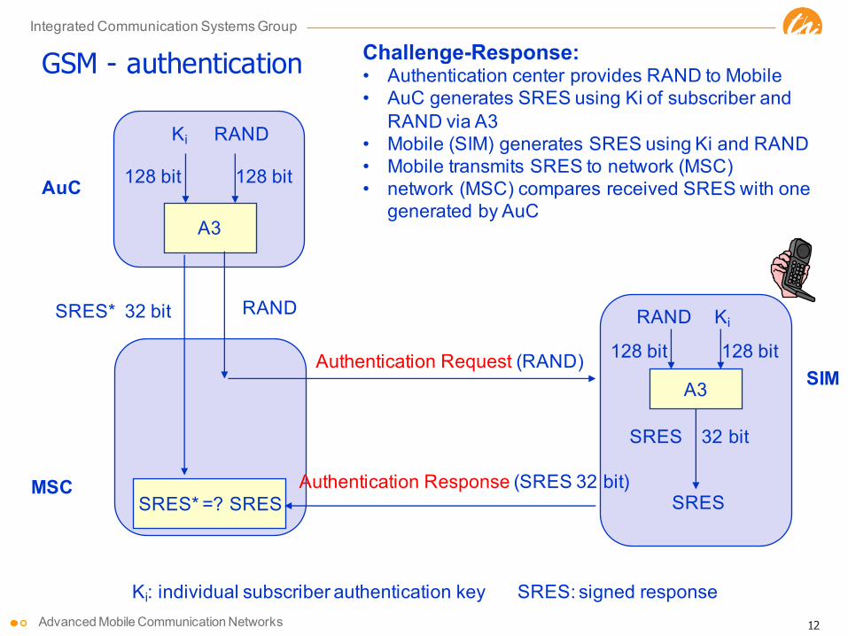
GSM - authentication
A3
RANDKi
128 bit 128 bit
RAND
SRES* =? SRES
A3
RAND Ki
128 bit 128 bit
SRES 32 bit
SRES
Authentication Request (RAND)
Authentication Response (SRES 32 bit)
AuC
MSC
SIM
Ki: individual subscriber authentication key SRES: signed response
SRES* 32 bit
Challenge-Response:• Authentication center provides RAND to Mobile• AuC generates SRES using Ki of subscriber and
RAND via A3• Mobile (SIM) generates SRES using Ki and RAND• Mobile transmits SRES to network (MSC)• network (MSC) compares received SRES with one
generated by AuC

13
Integrated Communication Systems Group
Advanced Mobile Communication Networks
GSM - key generation and encryption
A8
RANDKi
128 bit 128 bit
Kc64 bit
A8
RAND Ki
128 bit 128 bit
SRES
RAND
encrypteddata
MS with SIM
AuC
BTS
SIM
A5
Kc64 bit
A5MS
data data
cipherkey
Ciphering:• Data sent on air interface ciphered for security• A8 algorithm used to generate cipher key• A5 algorithm used to cipher/decipher data• Ciphering Key is never transmitted on air

14
Integrated Communication Systems Group
Advanced Mobile Communication Networks
2G to 3G Evolution: GSM - GPRS - UMTS
GPRS Core (PacketSwitched)
SGSN
GGSN
Inter-net
GSMRAN
Base stationBase stationcontroller
Base station
Base station
MSC
ISDN
GSM Core (Circuit switched)
HLRAuCEIR
GMSC
TransmissionATM based
GSM+GPRS

15
Integrated Communication Systems Group
Advanced Mobile Communication Networks
Circuit vs. Packet Switched Communication
Connection (e.g. voice, CS data) => principle for GSM & UTRAN design• clearly defined start and end times• no burstiness=> dedicated channels
minutesconnection
setupconnection
release
Packet session => supported by GPRS core, IMS, SAE, HSPA, LTE• packet arrival times are typically unknown to the system• traffic is highly bursty=> shared channels & packet scheduling
hours
seconds

16
Integrated Communication Systems Group
Advanced Mobile Communication Networks
GPRS (General Packet Radio Service)u Introducing packet switching in the networku Using shared radio channels for packet transmission over the air:
u multiplexing multiple MS on one time slotu flexible (also multiple) allocation of timeslots to MS
(scheduling by PCU Packet Control Unit in BSC or BTS) u using free slots only if data packets are ready to send
(e.g., 115 kbit/s using 8 slots temporarily)u standardization 1998, introduction 2001u advantage: first step towards UMTS, flexible data services
GPRS network elementsu GSN (GPRS Support Nodes): GGSN and SGSNu GGSN (Gateway GSN)
u interworking unit between GPRS and PDN (Packet Data Network)u SGSN (Serving GSN)
u supports the MS (location, billing, security)u HLR (GPRS Register – GR)
u maintains location and security information

17
Integrated Communication Systems Group
Advanced Mobile Communication Networks
carrierTS0 1 2 3 4 5 6 7
0 1 2 3 4 5 6 7
Multiplexing
Multislot capability
GPRS: Multiplexing and multislot allocation

18
Integrated Communication Systems Group
Advanced Mobile Communication Networks
GPRS servicesEnd-to-end packet switched traffic (peak channel rates)u 28 kbps (full use of 3 time slots, CS-1: FEC) u 171.2 kbps (full use of 8 time slots, CS-4: no FEC)Average aggregate throughput of a cell (Source: H. Menkes, WirelessWeb, Aug. 2002)u 95 kbps (for both up and downlink)u Assumptions: 4/12 reuse, realistic RF conditions, random trafficu Worse figures for individual TCP trafficAdaptive Coding Schemes (adaptive Forward Error Control – FEC)u CS 1: 9.05 Kbps/slotu CS 2: 13.4 Kbps/slotu CS 3: 15.6 Kbps/slotu CS 4: 21.4 Kbps/slot (no FEC)Problems and limitsu IP-based network => high latency, no guaranteesu Limited data rate: 28 kbps (3 slot/CS-1) - 64.2 kbps (3 slot/CS-4)u Latency/flow control problems with TCP
19
Integrated Communication Systems Group
Advanced Mobile Communication Networks
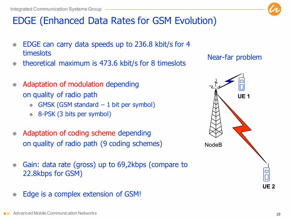
EDGE (Enhanced Data Rates for GSM Evolution)
u EDGE can carry data speeds up to 236.8 kbit/s for 4 timeslots
u theoretical maximum is 473.6 kbit/s for 8 timeslots
u Adaptation of modulation dependingon quality of radio path
u GMSK (GSM standard – 1 bit per symbol)u 8-PSK (3 bits per symbol)
u Adaptation of coding scheme dependingon quality of radio path (9 coding schemes)
u Gain: data rate (gross) up to 69,2kbps (compare to22.8kbps for GSM)
u Edge is a complex extension of GSM!
NodeB
UE 1
UE 2
Near-far problem

20
Integrated Communication Systems Group
Advanced Mobile Communication Networks
EDGE – Adaptive Modulation and Coding SchemesScheme Modulation Maximum
rate [kb/s]Code Rate Family
MCS-9 59.2 1.0 AMCS-8 54.4 0.92 AMCS-7 44.8 0.76 BMCS-6 29.6 / 27.2 0.49 AMCS-5
8PSK
22.4 0.37 BMCS-4 17.6 1.0 CMCS-3 14.8 / 13.6 0.80 AMCS-2 11.2 0.66 BMCS-1
GMSK
8.8 0.53 C

21
Integrated Communication Systems Group
Advanced Mobile Communication Networks
Payload for GPRS and EDGE

22
Integrated Communication Systems Group
Advanced Mobile Communication Networks
Differences of GSM/GPRS Compared to WLAN SystemsSpectrum management and utilization
u coverage and interference management due to cell planningu capacity and load management due to admission control and QoS supportu flexible cell size simplifies cost-efficient nationwide coverage
Mobility managementu fast, lossless HO due to make-before-break
General control structures and control philosophyu high reliability and QoS guaranties due to centralized/infrastructure-
based management and control of all resourcesEnergy
u high energy cost on network side, low cost on mobile due to passiv cellcamping instead of active association, paging mode and sleep cycles
Customer relationsu monthly/bi-yearly contracts, pay per serviceu security due to preshared credentials
Implementationu simple implementation of TDMA, e.g. with GNUradio and SDR

23
Integrated Communication Systems Group
Advanced Mobile Communication Networks
2G to 3G Evolution: GSM - GPRS – UMTS R99
GPRS Core (PacketSwitched)
SGSN
GGSN
Inter-net
GSMRAN
Base stationBase stationcontroller
Base station
Base station
UTRAN
Radio networkcontroller
Base station Base station
Base station
MSC
ISDN
GSM Core (Circuit switched)
HLRAuCEIR
GMSC
ATM based
GSM+GPRS+UMTS R99

24
Integrated Communication Systems Group
Advanced Mobile Communication Networks
2G to 3G Evolution: GSM - GPRS - UMTS R5 - IMS
GPRS Core (PacketSwitched)
SGSN
GGSN
Inter-net
GSMRAN
Base stationBase stationcontroller
Base station
Base station
UTRAN
Radio networkcontroller
Base station Base station
Base station
IP based
3G Core
GERANGERAN + UMTS R5 + IMS

25
Integrated Communication Systems Group
Advanced Mobile Communication Networks
UMTS – Macro Diversity in CDMA
BS 1BS 2
UE
CDMA is a single frequency system
Mobile user may be servedu by multiple base stations
=> soft handover=> combining in RNC
u by multiple cells from the same base station=> softer handover=> combining in base station
Due to increased redundancy, the combining of signals improves quality (BER) or allows to reduce required TX power to achieve given BER requirements.
Note that this is an extension of the make-before-break strategy where radio links are continuously added and deleted.

26
Integrated Communication Systems Group
Advanced Mobile Communication Networks
UMTS – Cell BreathingCDMA systems: cell size depends on the actual loading
u Additional traffic will cause higher interferenceu If the interference becomes too strong, users at the cell edge can no
longer meet SINR requirements to continue communication

27
Integrated Communication Systems Group
Advanced Mobile Communication Networks
UMTS – Mobility Management in Packet Domain
L1
RLC
PDCP
MAC
E.g., IP,PPP
Application
L1
RLC
PDCP
MAC
ATM
UDP/IP
GTP-U
AAL5
Relay
L1
UDP/IP
L2
GTP-U
E.g., IP,PPP
3G-SGSNUTRANMSIu-PSUu Gn Gi
3G-GGSN
ATM
UDP/IP
GTP-U
AAL5
L1
UDP/IP
GTP-U
L2
Relay

28
Integrated Communication Systems Group
Advanced Mobile Communication Networks
End-to-End Resource Management in UMTS (contr. plane)A sophisticated QoS architecture
Transl. Transl.
Adm.Contr
.Adm.Contr
.Adm.Contr
.Adm.Contr
.Adm.Contr
.
RAB Manager
UMTS BS Manager
UMTS BS Manager
UMTS BS Manager
Subscr. Control
Adm./Cap. Control
MT Gateway CN EDGE UTRAN
Ext. Service Control
Local Service Control
Iu BS Manager
Radio BS Manager
Iu NS Manager
UTRA ph. BS M
Radio BS Manager
UTRA ph. BS M
Local BS Manager
Adm./Cap. Control
Adm./Cap. Control
Adm./Cap. Control
Iu BS Manager
Iu NS Manager
CN BS Manager
Ext. BS Manager
CN BS Manager
service primitive interface protocol interface
BB NS Manager
BB NS Manager
TE Ext. Netw.
For details see 3GPP TS 23.207

29
Integrated Communication Systems Group
Advanced Mobile Communication Networks
End-to-End Resource Management in UMTS (user plane)
ResourceManager
Mapper
Classif.
Cond.
ResourceManager
ResourceManager
Mapper
ResourceManager
Mapper
ResourceManager
ResourceManager
Cond.
Classif.
Cond.
MT GatewayCN EDGEUTRAN
BB network serviceIu network serviceUTRA phys. BS
data flow with indication of direction
TE Ext.Netw.
Local BS External BS

30
Integrated Communication Systems Group
Advanced Mobile Communication Networks
Evolution from GSM to UMTS and LTE GSM: voice-dominated, dedicated channels, heavy statesGPRS: add support for packet data on shared channels; add IP-based core
networkEDGE: increased packet data capacity of GSM systemsUMTS: separate voice and packet data support; focus on dedicated channels and
heavy states, complicated RAN architecture and protocols due to macro diversity (soft handover) and QoS requirements
HSPA: improved support for packet data; emphasis on shared channels and fast radio resource management
IMS: support for IP-based services, e.g. voice (VoIP)LTE: strong packet data support (latency, throughput, control overhead), limited
state; simplified protocols; PS only, i.e. no CS core network
Evolution of technologyu from circuit switching to packet switchingu from slow, explicit setup and release of resources to fast channel-condition-
and demand-specific resource management

31
Integrated Communication Systems Group
Advanced Mobile Communication Networks
Evolution towards LTE – Architecture
• LTE radio system is a packet-only network - there is no support for circuit-switched services (no MSC)
• LTE started on a clean state - everything was up for discussion including the system architecture and the split of functionality between Radio Access Network (RAN) and Core Network (CN)
• 3GPP (3rd Generation Partnership Program) study items • „3G Long-term Evolution” (LTE) for new Radio Access and • “System Architecture Evolution” (SAE) for Evolved Network

32
Integrated Communication Systems Group
Advanced Mobile Communication Networks
LTE: Evolved Packet System (EPS) Architecture
eNB
eNB
eNB
MME/S-GW MME/S-GW
X2
EPCE-UTRAN
S1
S1
S1S1
S1S1
X2
X2
EPC = Evolved Packet Core
2 instead of 4 user plane entities
Key changesueNB: merging of base
station and RNC functionality
uS-GW: merger of SGSN and GGSN functionality

33
Integrated Communication Systems Group
Advanced Mobile Communication Networks
LTE: Requirements and Performance Targets

34
Integrated Communication Systems Group
Advanced Mobile Communication Networks
LTE Key Features (Release 8)
u Support for both FDD and TDD
u Adaptive modulation and codingu DL modulations: QPSK, 16QAM, and 64QAMu UL modulations: QPSK and 16QAM
u Hybrid ARQ in addition to ARQ
u Multi-antenna solutionsu (2 or 4) x (2 or 4) downlink and uplink supportedu Multi-layer transmission with up to four streamsu Multi-user MIMO also supported
u Implicit support for interference coordination

35
Integrated Communication Systems Group
Advanced Mobile Communication Networks
Multi-antenna Solutions
IEEE Communications Magazine • April 200948
ple-input multiple-output [MIMO], as well asmulti-user MIMO) with up to four antennas, andbeamforming. Which of the schemes (or whichcombination of the schemes) to use depends onthe scenario (Fig. 5). In the uplink, both open-and closed-loop transmit-antenna selection aresupported as optional features.
LTE transmit diversity is based on so-calledspace-frequency block coding (SFBC), comple-mented with frequency-switched transmit diversi-ty (FSTD) in the case of four transmit antennas[1]. Transmit diversity is primarily intended forcommon downlink channels to provide addition-al diversity for transmissions for which channel-dependent scheduling is not possible. However,transmit diversity also can be applied to user-data transmission, for example, to voice-over-IP(VoIP), where the relatively low user-data ratesmay not justify the additional overhead associat-ed with channel-dependent scheduling.
In case of spatial multiplexing, multiple anten-nas at both the transmitter (base station) andthe receiver (terminal) side are used to providesimultaneous transmission of multiple, paralleldata streams, also known as layers, over a singleradio link, thereby significantly increasing thepeak data rates that can be provided over theradio link. As an example, with four base-stationtransmit antennas and a corresponding set of (atleast) four receive antennas at the terminal side,up to four data streams can be transmitted inparallel over the same radio link, effectivelyincreasing the data rate by a factor of four.
LTE multi-stream transmission is pre-coderbased. A number of transmission layers aremapped to up to four antennas by means of aprecoder matrix of size NA×NL, where the num-ber of layers NL, also known as the transmissionrank, is less than or equal to the number ofantennas NA. The transmission rank, as well asthe exact precoder matrix, can be selected by thenetwork, based on channel-status measurementsperformed and reported by the terminal, alsoknown as closed-loop spatial multiplexing.
In the case of spatial multiplexing, by select-ing rank-1 transmission, the precoder matrix,which then becomes an NA×1 precoder vector,performs a (single-layer) beamforming function.More specifically, this type of beamforming canbe referred to as codebook-based beamforming
as the beamforming can be done only accordingto a limited set of pre-defined beamforming(precoder) vectors.
In addition to the codebook-based beam-forming as a special case of the LTE spatial mul-tiplexing, LTE also supports more generalnon-codebook-based beamforming. In contrast tocodebook-based beamforming, in the case ofnon-codebook-based beamforming, the terminalmust make an estimate of the overall beam-formed channel. To enable this, LTE providesthe possibility for the transmission of user equip-ment (UE)-specific reference symbols, transmit-ted using the same beamforming as the userdata, and enabled for the terminal to estimatethe overall beamformed channel.
POWER CONTROL ANDINTER-CELL INTERFERENCE COORDINATION
LTE provides (intra-cell) orthogonality betweenusers in both uplink and downlink, that is, atleast in the ideal case, no interference betweentransmissions within the same cell but only inter-ference between cells. Hence, LTE performancein terms of spectrum efficiency and availabledata rates is, relatively speaking, more limited byinterference from other cells (inter-cell interfer-ence) compared to WCDMA/HSPA, especiallyfor users at the cell edge. Therefore, the meansto reduce or control the inter-cell interferencepotentially can provide substantial benefits toLTE performance, especially in terms of the ser-vice (data rates, etc.) that can be provided tousers at the cell edge.
Uplink power control is one of the mecha-nisms in LTE used for this purpose. It is used tocontrol not only the received signal strength inthe intended cell, but also to control the amountof interference in neighboring cells. LTE uplink-power control supports fractional path-loss com-pensation, implying that users close to the cellborder use relatively less transmit power, andthus generate relatively less interference toneighbor cells. However, LTE provides moreadvanced interference-handling schemes as well.
Inter-cell interference coordination (ICIC) isin essence a scheduling strategy used to limit theinter-cell interference. A simple method toimprove cell-edge data rates is to restrict theusage of parts of the bandwidth statically, forexample, through a reuse larger than one. Suchschemes improve the signal-to-interference ratiosof the used frequencies. However, the loss due toreduced bandwidth availability is typically largerthan the corresponding gain due to higher signal-to-interference ratio, leading to an overall loss ofefficiency. Therefore, the LTE standard providestools for dynamic inter-cell-interference coordina-tion of the scheduling in neighbor cells such thatcell-edge users in different cells preferably arescheduled on complementary parts of the spec-trum when required. Note that a major differencefrom static reuse schemes is that LTE still allowsfor the total available spectrum to be used in allcells. Bandwidth restrictions are applied onlywhen motivated by traffic and radio conditions.
Interference coordination can be applied toboth uplink and downlink, although with somefundamental differences between the two links. In
!!
Figure 5. Multiple-antenna techniques in LTE.
Diversity for improvedsystem performance
Beam-forming for improved coverage(less cells to cover a given area)
Spatial-division multiple access(”MU-MIMO”) for improved capacity
(more users per cell)
Multi-layer transmission(”SU-MIMO”) for higher data rates
in a given bandwidth
PARKVALL LAYOUT 3/25/09 2:17 PM Page 48
36
Integrated Communication Systems Group
Advanced Mobile Communication Networks
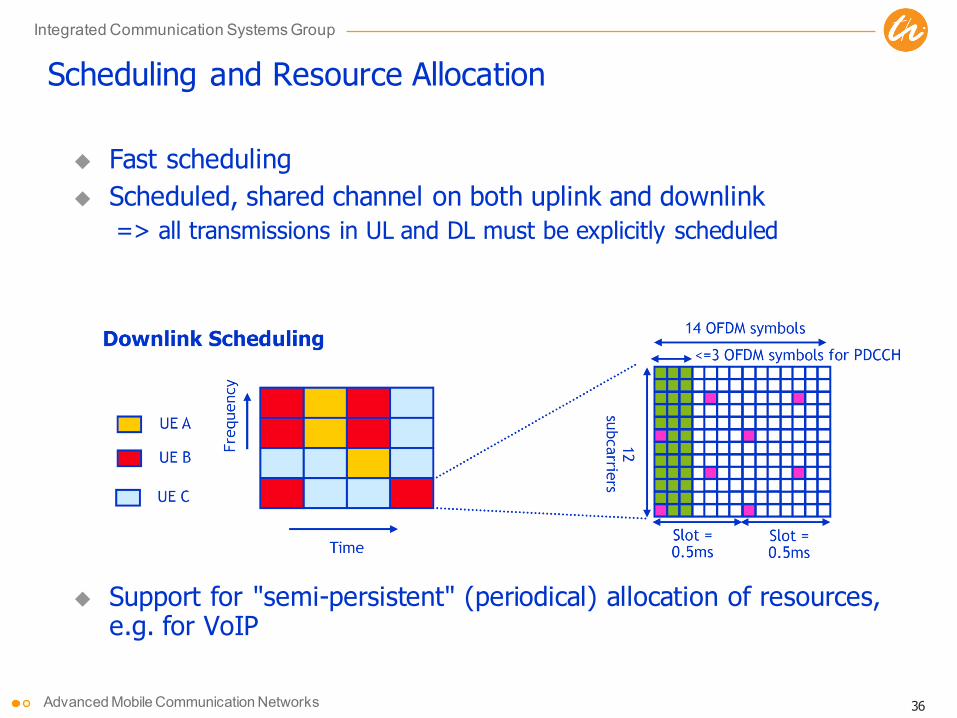
Scheduling and Resource Allocation
u Fast schedulingu Scheduled, shared channel on both uplink and downlink
=> all transmissions in UL and DL must be explicitly scheduled
u Support for "semi-persistent" (periodical) allocation of resources,e.g. for VoIP

37
Integrated Communication Systems Group
Advanced Mobile Communication Networks
Opportunistic SchedulingPrefer mobiles with good channel quality=> maximizes system throughput
Ensure fairness for users with continuously poor channel quality
NodeB
Sample Flow
Flow #1
Flow #3
UE 3
UE 2
UE 1
Flow #2

38
Integrated Communication Systems Group
Advanced Mobile Communication Networks
Interference Coordination

39
Integrated Communication Systems Group
Advanced Mobile Communication Networks
Self-Organization in LTE
Goal: minimize OPEX by automation of planning, optimization and repair
Use Cases for Self-organized Network Managementu Physical cell-ID automatic configuration (PCI)u Automatic Neighbor Relation (ANR)u Coverage and capacity optimization (CCO)u Inter-cell interference coordination (ICIC)u Random Access Channel (RACH) optimizationu Mobility load balancing optimization (MLB)u Mobility robust optimization (MRO)u Energy saving (power on/off)

40
Integrated Communication Systems Group
Advanced Mobile Communication Networks
References
LTE/SAEu A. Toskala et al, “UTRAN Long-Term Evolution,” Chapter 16 in Holma/ Toskala: WCDMA for UMTS, Wiley 2007u E. Dahlman et al, “3G Evolution, HSPA and LTE for Mobile Broadband,” Elsevier Journal, 2007u Special Issue on LTE/ WIMAX, Nachrichtentechnische Zeitung, pp. 12–24, 1/2007u 3rd Generation Partnership Project Long Term Evolution (LTE), official website:
http://www.3gpp.org/Highlights/LTE/LTE.htmu Technical Paper, “UTRA-UTRAN Long Term Evolution (LTE) and 3GPP System Architecture Evolution (SAE)”,
last update October 2006, available at: ftp://ftp.3gpp.org/Inbox/2008_web_files/LTA_Paper.pdf
Standardsu TS 36.xxx series, RAN Aspectsu TS 36.300, “E-UTRAN; Overall description; Stage 2”u TR 25.912, “Feasibility study for evolved Universal Terrestrial Radio Access (UTRA) and Universal Terrestrial
Radio Access Network (UTRAN)”u TR 25.814, “Physical layer aspect for evolved UTRA”u TR 23.882, “3GPP System Architecture Evolution: Report on Technical Options and Conclusions”
Self-organizing networks and LTEu Self-organizing networks and LTE, http://www.lightreading.com/document.asp?doc_id=158441u NGMN Recommendation on SON and O&M Requirements, Dec. 5, 2008, NGMN,
http://www.ngmn.org/uploads/media/NGMN_Recommendation_on_SON_and_O_M_Requirements.pdf