moab umtra project health physics plan - energy
TRANSCRIPT
Prepared by the Technical Assistance Contractor under contract number DE-EM0005014 and the Remedial Action Contractor under contract number DE-DT0011049
for the U.S. Department of Energy Office of Environmental Management, Grand Junction, Colorado.
Moab UMTRA Project Health Physics Plan Revision 4 March 2021
DOE-EM/GJ3003

U.S. Department of Energy Moab UMTRA Project Health Physics Plan Revision 4 March 2021 DOE-EM/GJ3003
Page i
DOE-EM/GJ3003
Moab UMTRA Project Health Physics Plan
Revision 4
Review and Approval
3/15/2021
XRonald R. DailyRAC Radiological Control ManagerSigned by: RONALD DAILY (Affiliate)
3/15/2021
XSteven D. RimaRAC ESH&Q ManagerSigned by: Steve Rima
3/15/2021
X Greg D. ChurchGreg D. ChurchRAC Project ManagerSigned by: GREGORY CHURCH (Affiliate)
3/16/2021
X Swaine SkeenSwaine SkeenTAC Senior Program ManagerSigned by: Swaine Skeen
U.S. Department of Energy Moab UMTRA Project Health Physics Plan Revision 4 March 2021 DOE-EM/GJ3003
Page ii
Revision History
Revision Number Date Reason for Revision 0 September 2007 Initial issue. 1 November 2011 Minor changes and clarifications made following biannual review.
2 November 2013 Addition of Addendum A, “Radiological Evaluation, Decontamination, and Final Unrestricted Release Survey of the Fernald Trackmobile.”
3 March 2015 Removal of Addendum A. “Radiological Evaluation, Decontamination, and Final Unrestricted Release Survey of the Fernald Trackmobile.”
4 March 2021 Plan update and replace Attachment 1 due to incorrect input values.

U.S. Department of Energy Moab UMTRA Project Health Physics Plan Revision 4 March 2021 DOE-EM/GJ3003
Page iii
Contents Section Page Acronyms and Abbreviations ..........................................................................................................v 1.0 Introduction ........................................................................................................................1 2.0 General Requirements .......................................................................................................1
2.1 ALARA ....................................................................................................................2 2.2 Radiological Work Permit Process ..........................................................................2 2.3 Radiological Monitoring ..........................................................................................3
3.0 Existing Radiological Conditions .....................................................................................3 3.1 General Conditions ..................................................................................................3 3.2 Radionuclide Constituents .......................................................................................3 3.3 Dosimetry Parameters of Select RRM Radionuclides .............................................6 3.4 Radon and Thoron....................................................................................................9
3.4.1 General Information and Terminology ........................................................9 3.4.2 Current Regulations and Units of Measurement ..........................................9
4.0 RWPs and RCT Job Coverage .......................................................................................10 5.0 General Area Air Monitoring .........................................................................................11
5.1 Airborne Particulate Isotopes of Concern ..............................................................11 5.1.1 Corrections for Particle Size Greater than 10 µM AMAD ........................12 5.2 Radon .....................................................................................................................12 5.3 Radionuclides in the Mill Tailings .........................................................................13
5.3.1 Factors Associated with Air Particulate Sampling ....................................13 5.3.2 Modified DAC Equation ............................................................................13
6.0 Individual Monitoring .....................................................................................................14 6.1 Radon Dosimetry ...................................................................................................15
7.0 Internal Dose Assessments ..............................................................................................15 8.0 Exposure Control and Personnel Monitoring ...............................................................16 9.0 Contamination Control ...................................................................................................17 10.0 Personnel Responsibilities ...............................................................................................17
10.1 Operations/Site Manager .......................................................................................17 10.2 RCM .......................................................................................................................18 10.3 RCTs and Supervisors............................................................................................18
11.0 Radiological Incidents and Reporting ............................................................................18 12.0 Personnel Entry and Exit Protocols ...............................................................................18
12.1 Entering and Exiting Controlled Areas ..................................................................18 12.2 Entering the Radiological Area Access Control Point ...........................................18 12.3 Exiting the Radiological Area Access Control Point .............................................19
13.0 PPE and Anti-C Clothing ................................................................................................20 14.0 Posting and Labeling .......................................................................................................20 15.0 Receipt and Control of Radioactive Material and Sources ..........................................21
15.1 RAM Control .........................................................................................................22 15.2 Source Control .......................................................................................................22
16.0 References .........................................................................................................................22

U.S. Department of Energy Moab UMTRA Project Health Physics Plan Revision 4 March 2021 DOE-EM/GJ3003
Page iv
Section Page Figures
Figure 1. U-238 Decay Chain ........................................................................................................3 Figure 2 U-235 Decay Chain ........................................................................................................4 Figure 3. Th-232 Decay Chain .......................................................................................................6
Tables
Table 1. Dosimetry and Monitoring Information Summary ........................................................7 Table 2. Dosimetry Information for Select Radionuclides ..........................................................8 Table 3. Radon and Thoron Terminology ....................................................................................9 Table 4. Radium and Thoron Limits, Descriptions, and Notes .................................................10 Table 5. Moab UMTRA Project Mill Tailing Isotopic Ratios ...................................................13 Table 6. Fixed + Removable Radioisotope Limits ....................................................................19
Attachments
Attachment 1 White Paper- Radiological Control Clarification of the Moab UMTRA
Projects Special Permit Authorization DOT-SP 14283 Section 7. (4) Attachment 2 White Paper -Technical Basis for Conducting a Statistical Release of
Containers from a Contamination Area on the Moab UMTRA Project Attachment 3 White Paper -Evaluating the Radioactive Release effects of an Atlas
Building Structural Fire Attachment 4 White Paper –Adjusting the Derived Air Concentration Values at the Mill
Tailings Pile based on Isotopic Analysis Attachment 5 White Paper -Particle Size and Effects Study
White Paper presented in the Attachments Section are provided to capture programmatic changes and decisions on the radiological protection program.

U.S. Department of Energy Moab UMTRA Project Health Physics Plan Revision 4 March 2021 DOE-EM/GJ3003
Page v
Acronyms and Abbreviations
Ac actinium ACL administrative control level ALARA as low as reasonable achievable ARA airborne radioactivity area Bi bismuth CA Contamination Area CED committed effective dose CFR Code of Federal Regulations cm2 square centimeters DAC derived air concentration DOE G DOE Guide DOE STD DOE Standard DOE U.S. Department of Energy dpm disintegrations per minute Ew emission factor F equilibrium factor HPP Health Physics Plan hr hour ICRP International Commission on Radiological Protection LLGA long-lived gross alpha MeV mega electron volts mrem millirem Pa protactinium Pb lead PCM personnel contamination monitor Po polonium PPE personal protective equipment Ra radium RAC Remedial Action Contractor RAM radioactive material RAP Remedial Action Plan RCM Radiological Control Manager RCT Radiological Control Technician RMA radiological materials area Rn radon RRM residual radioactive material RWP radiological work permit Th thorium TLD thermoluminescent dosimeter TQT Task Qualified Technician U uranium UMTRA Uranium Mill Tailings Remedial Action WL working level

U.S. Department of Energy Moab UMTRA Project Health Physics Plan Revision 4 March 2021 DOE-EM/GJ3003
Page 1
1.0 Introduction This Moab UMTRA Project Health Physics Plan (HPP) describes the radiological controls specifically planned for the Moab Uranium Mill Tailings Remedial Action (UMTRA) Project located in Moab and Crescent Junction, Utah. For detailed technical information related to Internal Dosimetry, Radiobioassay and Air Monitoring see the following Technical Basis Manuals: • Internal Dosimetry Technical Basis Manual (DOE-EM/GJRAC1913) • External Dosimetry Technical Basis Manual (DOE-EM/GJRAC1894) • Bioassay Technical Basis Manual (DOE-EM/GJRAC1893) • Air Monitor Technical Basis Manual (DOE-EM/GJRAC1889)
The HPP documents the requirements of the U.S. Department of Energy (DOE) and the Remedial Action Contractor (RAC) that apply to radiological protection on the Moab Project. Reference to the Moab Project in this document refers to both the Moab and Crescent Junction sites. The HPP documents the Radiological Protection Program elements and services provided to the Project by the RAC and its subcontractors. The principal requirements for radiological protection at DOE facilities are specified in Title 10 Code of Federal Regulations Part 835 (10 CFR 835), “Occupational Radiation Protection.” The radiological protection requirements defined by 10 CFR 835 that are implemented at the Moab Project are specified in the Moab UMTRA Project Radiation Protection Program (DOE-EM/GJ610). The HPP identifies radiological hazards and controls specific to maintenance and operations of the Moab Project and satisfies requirements related to occupational as low as reasonably achievable (ALARA) planning and review. Materials and/or equipment that have been received from another site that contain a different isotopic mix from that of the Moab UMTRA Project, must undergo a comprehensive technical review. If there are inconsistencies in the HPP and the new isotopic mix, an addendum to the plan must be generated. The addendum must clearly describe all the differences associated with new isotopic source terms and address all the necessary radiological controls to ensure compliance with 10 CFR 835. This document will be revised as the scope of the Project matures. The following elements are addressed herein. • Project operations • Radiological hazards associated with site maintenance • Radiological hazards associated with bulk waste retrieval from the pile and bulk waste transfer
to load-out containers • Radiological hazards associated with the packaging and staging of waste material before and/or
during transfer to the disposal site • Engineering controls, administrative controls, and personal protective equipment (PPE) or anti-
C clothing implemented to mitigate radiological hazards • Estimated radiological dose rates and personnel exposure • Radiological Control Technician (RCT) coverage requirements • ALARA goals 2.0 General Requirements

U.S. Department of Energy Moab UMTRA Project Health Physics Plan Revision 4 March 2021 DOE-EM/GJ3003
Page 2
2.1 ALARA Radiological requirements for maintenance and operations ensure all functions and activities are performed in such a way as to keep internal and external exposure to ionizing radiation ALARA. The ALARA philosophy requires any exposure to ionizing radiation by general employees or the public to be minimized to the extent that social, technical, economic, practical, and public policy considerations allow. The Moab Project is committed to keeping exposure ALARA through engineering (design), management (administrative controls), and supervision (procedures). This principle is implemented by the following six key elements. 1. Reducing time spent within radiological areas 2. Reducing exposure to the source(s) of radioactivity 3. Increasing the distance from source(s) of radioactivity 4. Providing containment of and shielding from sources of radioactivity 5. Minimizing internal exposures through monitoring and the use of PPE 6. Reducing labor requirements for operations in radiological areas These six key elements are weighed against economic factors, technical feasibility, practicality, public policy, and social needs to implement the best design and operational parameters. Three approaches are incorporated in design, construction, and operations. 1. Operational layouts (designs) and exposure causing activities are systematically
evaluated (with radiological and other safety considerations as the highest priorities) to keep internal and external exposures to individuals and contamination releases to the environment ALARA.
2. Personnel are trained in ALARA principles and practices. Additionally, personnel shall adhere to radiological control requirements during operations, maintenance, and support activities to minimize internal and external radiation exposures.
3. Personnel and facilities at the Moab Project are monitored for radiation hazards, including internal and external exposure and contamination levels. This monitoring is documented to verify that exposures are ALARA.
2.2 Radiological Work Permit Process The RAC controls radiological work through a radiological work permit (RWP) process. An RWP is used to designate the specific radiological controls, precautions, surveillance, and/or instructions to personnel. Training requirements, PPE, exposure limitations, dosimeter requirements, steps to minimize the spread of contamination, steps to limit radiation exposure to adjacent personnel, and provisions for augmented monitoring and surveillance are all specified by Radiological Control on RWPs. In addition, RWPs provide a means to trend job exposures by inclusion of an entry log and dose record sheet. Employees performing radiological work are required to read, understand, sign, and abide by the requirements prescribed on the RWP.

U.S. Department of Energy Moab UMTRA Project Health Physics Plan Revision 4 March 2021 DOE-EM/GJ3003
Page 3
2.3 Radiological Monitoring Radiological monitoring is performed at the Moab Project to assess changes in radiological conditions, assess airborne concentrations of radon (Rn) and radioparticulates, prevent the spread of radioactive contamination, and limit personnel exposure. Radiological monitoring for the Project will be performed by: • Personnel contamination monitoring. • Area radiation monitoring. • Contamination monitoring. • Air sampling (boundary, general area, and breathing zone). 3.0 Existing Radiological Conditions 3.1 General Conditions Significant quantities of by-product material called residual radioactive material (RRM) are produced during milling operations of uranium (U) ore. This material is generally collected in a slurry and pumped to tailings ponds. These ponds are dewatered via evaporation, resulting in mill tailings piles. The Moab pile was subsequently covered by earth from the surrounding site. Because the radioactive constituents in the tailings mix are greatly diluted by the non-radioactive portion of the ore, the specific activity of RRM is very low, generally on the order of nanocuries per gram or less. The contaminants in the soil making up the cover and surrounding the pile are even less concentrated. 3.2 Radionuclide Constituents The RRM consists of radioactively inert crushed rock, water, residual milling chemicals, residual uranium, and small quantities of thorium (Th)-230, Th-232, radium (Ra)-226, and their decay progeny. The presence of Th-232 is dependent on the ore body mined to produce the uranium ore and may be found in varying ratios throughout the pile (as multiple ore bodies may have been used to supply the mill). Due to the low specific activity of mill tailings and the large particle size of the dust (5 to 10 micron activity mean aerodynamic diameter), surface contamination in tailings handling areas do not present an acute exposure scenario, although standard precautions should be taken to keep the materials from becoming airborne. In mill tailings, approximately 92 percent or more of the activity due to the uranium isotopes has been removed in the milling process. Except for uranium (U)-235, the actinium decay chain radionuclides are assumed to be in equilibrium with each other and exist at 4.7 percent of the U-238 decay chain activity. Uranium, radium, and thorium occur in three natural decay series, headed by U-238, U-235, and Th-232, respectively. In nature, the radionuclides in these three series are approximately in a state of secular equilibrium, in which the activities of all radionuclides within each series are nearly equal. The radionuclides of these three decay series are shown in Figures 1, 2, and 3, along with the primary modes of decay for each. In mill tailings, the top of the decay chain has been removed, leaving Th-230, Ra-226, and the decay progeny of radium (mainly radon) as the primary radionuclides of concern.

U.S. Department of Energy Moab UMTRA Project Health Physics Plan Revision 4 March 2021 DOE-EM/GJ3003
Page 4
As shown in Figure 1, most of the uranium has been removed in the milling process. The two long-lived radionuclides (Th-230 and Ra-226) may not be co-located in equal activity concentrations due to various chemical extraction and sorting processes that have occurred. Lead (Pb)-210 should be reasonably close to full equilibrium with Ra-226. A fraction of the Ra-226 progeny is liberated via the airborne release of radon as shown below. • Bismuth (Bi)-214 has four gammas at 0.609, 1.12, 1.765, and 2.204 megaelectron volts (MeV). • Pb-214 has three gammas at 0.242, 0.295, and 0.352 MeV.
α = alpha; β = beta; Pa = protactinium; Po = polonium; µs = microseconds
Figure 1. U-238 Decay Chain
α 140 days
β 5 days
β 22 years
α 240,000 years
β 1.2 minutes
α 160 µs
β 20 minutes
β 27 minutes
α 3.1 minutes
α 3.8 days
α 1,600 years
α 77,000 years
β 24 days
U-238
Th-234
Pa-234m
U-234
Th-230
Ra-226
Rn-222
Po-218
†Pb-214
*Bi-214
Po-214
Pb-210
Bi-210
Po-210
Pb-206, Stable
α 4.5 billion years
Notes: *Bi-214 emits 4 strong gammas – MeV (% yield): 0.609 (46.1%), 1.12 (15.0%), 1.765 (15.9%), and 2.204 (5%). †Pb-214 emits 3 strong gammas – MeV (% yield): 0.242 (7.5%), 0.295 (19.2%), and 0.352 (37.1%)
Radon

U.S. Department of Energy Moab UMTRA Project Health Physics Plan Revision 4 March 2021 DOE-EM/GJ3003
Page 5
The U-235 shown in Figure 2 is a very small fraction of the total uranium found in nature; it makes up about 0.72 percent, by weight of the total uranium. On an activity basis, U-235 represents about 4.7 percent of the U-238 activity.
α = alpha; β = beta; Pa = protactinium; Po = polonium; Tl = thallium; y = years
Figure 2. U-235 Decay Chain Th-232 is not a decay product of uranium; it is the lead radionuclide of its own decay chain, depicted in Figure 3. Additionally, it is commonly not a principle element associated with uranium ore bodies, and thus it may or may not be measured above background levels where uranium is found. On the other hand, Th-230 is a decay progeny of U-238 and should naturally be found where uranium is found.
α 18.7 days (98.6%)
α 11.4 days
β 4.8 minutes
α 4.0 seconds
α 2.1 minutes
β 36 minutes
α 33,000 years
α 1.8 milliseconds
α 21.8 years
β 25.5 hours
*†U-235
Th-231
*Pa-231
Ac-227
Ra-223
*Pb-211
*Rn-219
Po-215 *Bi-211
Tl-207
Pb-207, Stable
α 700 million years Notes: *The radionuclide is also a significant gamma emitter. †U-235 is, on an activity basis, about 2.3% of the U-238/234 activity. U-235 comprises approximately 0.72% of the total uranium mass, by weight.
Th-227

U.S. Department of Energy Moab UMTRA Project Health Physics Plan Revision 4 March 2021 DOE-EM/GJ3003
Page 6
α = alpha; β = beta; Pb = lead; Po = polonium; Tl = thalium
Figure 3. Th-232 Decay Chain 3.3 Dosimetry Parameters of Select RRM Radionuclides Tables 1 and 2 provide a listing of summary information including, the internal and external technical approach position document, including the Moab UMTRA Project Remedial Action Plan (RAP) (DOE-EM/GJ1547) and the International Commission on Radiological Protection (ICRP) Publication 68, “Dose Coefficients for Intakes of Radionuclides by Workers.” The derived air concentration (DAC) values provided in 10 CFR 835 are also provided in Table 2 for convenience. This information is pertinent to the design and implementation of the present work place and individual monitoring program used by the RAC.
α 310 nanoseconds β 22 minutes 64%)
β 3.1 minutes
α 56 seconds
α 61 minutes (36%) β
11 hours
β 6.1 hours
α 3.7 days
α 0.15 seconds
α 1.9 years
β 5.8 years
Th-232
Ra-228
*Ac-228
Ra-224
Th-228
*Pb-212
Rn-220
Po-216
*Bi-212
*Tl-208
Pb-208, Stable
α 1.4 E 10 years Notes: *The radionuclide is also a significant gamma emitter.
Po-212
Thoron

U.S. Department of Energy Moab UMTRA Project Health Physics Plan Revision 4 March 2021 DOE-EM/GJ3003
Page 7
Table 1. Dosimetry and Monitoring Information Summary
Item/Question Response/Comment Source Radionuclides of
concern for internal dosimetry due to inhaled
particulates
Primary: Pa-231, Ac-227, Th-230, Ra-226, Pb-210, Po-210 Secondary: Th-227, Ra-223, Bi-214, Bi-210, Th-232,
Th-228, Po-214 All others contribute <0.1% on an individual basis
to the accumulated dose
RAP
Aerosol size distribution
Mean particle size of >10 µm over 99% of the particles by mass for tailings. Detailed experimental studies conducted by the Low Dose
Radiation Research Program resulting in a conservative assumption of 10 µm is being used, based on the particle size of Th-230
component, which tended to be associated with a smaller AMAD, on average. ICRP 68 values are based upon a 5 µm (AMAD) and are thus conservatively applied without modification. It should be noted
that the preamble to Appendix A of 10 CFR 835 allows a modification to the DAC value and/or to dose assessment when the measured
AMAD differs significantly from the assumed AMAD.
RAP ICRP 103/68
HPP 10 CFR 835
Retroactive air concentration assumptions
The results of radio analysis may be used to recalculate the airborne exposure environment experienced by workers. RAP
μm = micrometer; AMAD = activity median aerodynamic diameter; BS = bone surface; CED = committed effective dose; LNG = lung; LLGA = long-lived gross alpha; Pa = protactinium; Po = polonium; TBD = technical basis document ICRP 68, “Does Coefficients for Intakes of Radionuclides by Workers” ICRP 103, “The 2007 Recommendations of the International Commission on Radiological Protection”

U.S. Department of Energy Moab UMTRA Project Health Physics Plan Revision 4 March 2021 DOE-EM/GJ3003
Page 8
Table 2. Dosimetry Information for Select Radionuclides
Radionuclide Dosimetry Parameters Source
U Isotopes
Soluble chemical form [Class F] Decay Mode: Alpha DAC: 5E-10 µCi/mL
U-Nat, weighted, DCF BS = 38,907.4 mrem/µCi U-Nat, weighted, DCF Eff = 2,257.1 mrem/µCi
RAP ICRP 68
10 CFR 835
Pa-231
Conservatively assumed as Class M – most restrictive Decay mode: Alpha DAC: 1E-12 µCi/mL
DCF, BS = 1.63E7 mrem/µCi (most limiting) DCF, Eff = 3.30E5 mrem/µCi
ICRP 68 10 CFR 835
Ac-227
Conservatively assumed as Class F – most restrictive Decay Mode: Beta
DAC: 2E-13 µCi/mL DCF, BS = 1.63E07 mrem/µCi DCF, Eff = 3.30E05 mrem/µCi
RAP HPPICRP 68 10 CFR 835
Th-230
Insoluble chemical form [Class S in ICRP 103, “2007 Recommendations of the International Commission on Radiological
Protection,” terms] Decay Mode: Alpha DAC: 4E-11 µCi/mL
DCF, BS – 518,518.5 mrem/µCi DCF, Eff = 26,666.7 mrem/µCi
RAP
10 CFR 835
Ra-226
Class M (Only Class) Decay Mode: Alpha DAC: 2E-10 µCi/mL
DCF, LNG 62963.0 mrem/µCi DCF, Eff = 8148.1 mrem/µCi (most limiting)
RAP ICRP 68
10 CFR 835
Pb-210
Class F (only class listed) Decay Mode: Beta DAC: 1E10 µCi/mL
DCF, BS = 1.33E5 mrem/µCi (most limiting) DCF, Eff = 4.07E3 mrem/µCi
ICRP 68 10 CFR 835
Po-210
Class M (most conservative) Decay Mode: Alpha DAC: 2E-10 µCi/mL
DCF, LNG = 6.30E4 mrem/µCi DCF, Eff = 8.15E3 mrem/µCi (most limiting)
ICRP 68 10 CFR 835
μCi = microcurie; BS = bone surface; DCF = dose correction factor; Eff = effective dose; = LLG = long-lived gross; LLGA = long-lived gross alpha; LNG = lung; mL = milliliter; mrem = millirem; Pa = protactinium; Po = polonium; TBD = technical basis document; U-Nat = natural uranium ICRP 68, “Does Coefficients for Intakes of Radionuclides by Workers” ICRP 103, “The 2007 Recommendations of the International Commission on Radiological Protection

U.S. Department of Energy Moab UMTRA Project Health Physics Plan Revision 4 March 2021 DOE-EM/GJ3003
Page 9
3.4 Radon and Thoron 3.4.1 General Information and Terminology Moab UMTRA Project workers are occupationally exposed to radon gas (Rn-222/Rn-220), herein referred to as radon and thoron, respectively, throughout the remainder of this document (see Figures 1 and 3). A worker’s exposure to this hazard is a result of his or her proximity to and handling of tailings materials bearing the parents, Ra-226 and Th-232. Much of the discussion contained in this section is taken from the DOE document, “Occupational Exposure to Radon and Thoron” (PNNL-14108). However, when possible, the information provided in this document has been summarized and/or simplified, thus losing some of the technical nuances contained in that document; however, this is done in an effort to provide a concise and usable technical basis for radon and thoron monitoring. According to the ICRP, studies of uranium miners and other underground mines have shown that high exposure to the short-lived progeny of radon significantly increases the risk of lung cancer in human beings, especially among smokers. Radon and its short-lived progeny are continuously produced by decay of Ra-226. Airborne concentrations of radon progeny (polonium [Po]-218, Pb-214, Bi-214, and Po-214) are of interest due to their potential for deposition in the lung, leading to subsequent irradiation of lung tissue by alpha emission from Po-218 and Po-214. Thoron and its progeny are continuously produced by the decay of Ra-224 (a decay product in the Th-232 decay chain), hence the name thoron. In contrast with radon, substantially less thoron normally reaches and accumulates in the breathing zone due to its short half-life, which is 56 seconds for thoron versus 3.8 days for radon. In air, there is a complex and dynamic relationship between radon and thoron and their short-lived progeny. As a result, many physical quantities and units (Table 3) are used when discussing exposure levels, measurement terms, and risk. For instance, because the progeny may not be in radioactive equilibrium with the parent or may be removed from air through deposition and other processes, the equilibrium factor (F) is used to describe the fraction of maximum possible progeny present based on the amount present. Radium dosimetry is sharply skewed by assumptions made concerning the equilibrium factor.
Table 3. Radon and Thoron Terminology
Abbreviation Term Description pCi/L picocuries per liter A measure of airborne activity per unit volume air,
due to radium and/or thoron.
WL working level
A measure of the alpha particle energy potentially emitted by any mixture of radium/thoron progeny per unit volume of air. 10 CFR 835 defines a WL as any combination of short-lived
decay products in one liter of air, without regard to the degree of equilibrium, that will result in the ultimate emission of
1.3 E+ 05 MeV of alpha energy.
WLM working level month One month being 170 hours of exposure at a concentration of one WL.
F equilibrium factor The fraction of progeny energy (WL) possible, per unit of radon or thoron.

U.S. Department of Energy Moab UMTRA Project Health Physics Plan Revision 4 March 2021 DOE-EM/GJ3003
Page 10
3.4.2 Current Regulations and Units of Measurement 10 CFR 835, as amended June 8, 2007, adopts exposure limits based on information contained in ICRP Publication 65; “Protection Against Radon-220 at Home and at Work,” and in DOE Standard (STD)-1121-98, “Internal Dosimetry.” These limits, along with notes and examples meant to clarify their use, are presented in Table 4.
Table 4. Radium and Thoron Limits, Descriptions, and Notes
Isotope Limit Description/Notes Source
Th (Rn-220) Ra (Rn-222)
1E-8 µCi/mL 8E-8 µCi/mL
DAC. This value assumes 100% F with progeny.
This would be a measurement of filtered (i.e., non-progeny laden) air in a chamber of some
kind. A measurement of this type, in these units, is not commonly performed.
10 CFR 835 Appendix A Footnote 5 allows this DAC value to be modified by assuming a differing value for F via actually measured or
demonstrated equilibrium factors by the following equation:
DAC modified = DAC x
(1.00/fraction actual or demonstrated)
10 CFR 835
Th (Rn-220) Ra (Rn-222)
2.5 WL 0.83 WL
The DAC values discussed above may be replaced by these WL values for appropriate
limiting of decay product conditions.
A WL is generally measured by passing a certain volume of air through a filter and
collecting the short-lived progeny. The alpha activity on the filter is then measured and,
based upon various measurement protocols and algorithms, a WL concentration estimate
is provided.
10 CFR 835
Th (Rn-220) Ra (Rn-222)
30 WLM 10 WLM
2.5 WL x 2040 hrs/WLY x 170 hrs/WLM 0.83 WL x 2040 hrs/WLY x 170 hrs/WLM
IAEA, 1994, Table II-I. Safety Reports Series
33, “Radiation Protection Against Radon in
Workplaces Other than Mines”
Th (Rn-220) Ra (Rn-220)
10 pCi/L 80 pCi/L
1 DAC in pCi/l ( i.e. DAC in µCi/mL x 1E6 pCi/µCi x
1E-3 ml/L). The DAC, by definition, equates to an exposure rate of approximately 2.5 mrem/hr and assumes 100% equilibrium
conditions. By extension, these “DAC” values are able to be modified based upon actual or
demonstrated equilibrium conditions.
IAEA Safety Reports Series 33, “Radiation
Protection Against Radon in Workplaces
Other than Mines”
F = equilibrium factor; hr(s) = hour(s); IAEA = International Atomic Energy Agency; mrem/hr = millirems per hour; µCi/mL = microcuries per milliliter; pCi/L = picocuries per liter; WL = working level; WLM = working level month; WLY = working level year 4.0 RWPs and RCT Job Coverage RWPs will be generated by Radiological Control and approved by Radiological Control and site management. Work may not begin until the appropriate RWP has been approved and workers briefed and signed off on RWP they are working to. The RWP informs workers of area radiological conditions, work controls, PPE, and entry/exit requirements. RWPs are required for activities at the Moab Project that include, but are not limited to:

U.S. Department of Energy Moab UMTRA Project Health Physics Plan Revision 4 March 2021 DOE-EM/GJ3003
Page 11
• Opening of enclosures where radon gas and progeny can collect. • Any work within the Contamination Area (CA) on contaminated or potentially
contaminated equipment and some Radiological Buffer Areas (RBA) as deemed necessary by radiological control manager.
Workers will be briefed on the content, requirements, and radiological conditions of an RWP by a supervisor or RCT. Workers shall sign the acknowledgment sheet one time (per revision to the RWP) to indicate an understanding of the requirements of the RWP. Workers shall sign a daily sign-in sheet/computer database on the RWP applicable to the work they are going to perform before entering the work area and shall sign out upon exiting these areas. With reference to the daily sign-in sheet, a worker shall only be signed in on one RWP at any one time. RCT coverage will be provided as indicated on the applicable RWP. RCTs will perform frequent and timely surveys to ensure detection and characterization of contamination, if present. An RCT will periodically monitor radon concentrations in or around active work areas. 5.0 General Area Air Monitoring General area air samples will be collected to monitor trends of airborne radioactive particulate activity concentrations and to ensure compliance with good work practices for control of radionuclides. Occupational air monitoring for radioparticulates will be performed routinely at designated locations to evaluate concentrations against the potential for a person to exceed 40 DAC-hours (hrs) in a year and to be trended against 2 percent of the effective Moab Project DAC. When the DAC is based on stochastic effects, this translates to a committed effective dose (CED) of 100 millirems (mrem). The Moab Project routine monitoring program involves both monitoring of the workplace and the workers. Workplace monitoring is the primary means of assessing workplace conditions for implementation of engineering and administrative controls to limit worker exposure. 5.1 Airborne Particulate Isotopes of Concern The most limiting radioisotopes as determined through sampling data will be based on Ac-227, protactinium (Pa)-231, Th-230, and Ra-226, which collectively account for approximately 95 percent of the internal dose scenario (bone surface). A derived DAC, based on the isotopic ratios and individually assigned DACs, will be determined and verified through sampling data and calculations as the Project progresses. RRM contains elevated activity concentrations of radium, thorium, and associated decay products. These radionuclides also contribute to an elevated, direct penetrating gamma radiation field in the vicinity of soils piles, along with the continual emission of gas and progeny to the atmosphere.

U.S. Department of Energy Moab UMTRA Project Health Physics Plan Revision 4 March 2021 DOE-EM/GJ3003
Page 12
5.1.1 Corrections for particle size greater than 10 µm AMAD While large particles (>10 µm) are not respirable and therefore do not result in measurable dose, particle sizes greater than 1 µm but below 10 µm have smaller assigned dose, as they (in general) do not penetrate as far into the lung and are easier for the body to remove. The Integrated Modules for Bioassay Analysis (IMBA) software was used to calculate Effective Dose for various particle sizes which clearly demonstrates an inverse relationship between dose and particle size. Approximately 91% of the respirable dust is in the 1 µm category, with 9% being larger particle sizes. It is a conservative assumption to consider all the activity that is respirable to be 1 µm AMAD, because the 9% portion that is greater than 1 µm has a lesser dose consequence. Approximately 65.9% of the particles in routine measurements of airborne radioactivity in the air are respirable, and therefore all of the airborne measurements should be multiplied by 0.659 to calculate an “effective air concentration.” This value is the 95% upper confidence level of the actual measured average respirable fraction of airborne radioactive material of 49% (see Table 2). The value of 65% is conservative, and since the respirable fraction is largely 1 µm in aerodynamic diameter, no dose corrections based on particle size are necessary following the activity correction. When this respirable fraction correction is applied to the internal dose calculations at the Moab UMTRA Project, the internal dose consequences will drop by 35.6% (removing non-respirable fraction). NWP recommends that this practice should be implemented to accurately calculate and assign dose from airborne radioactive particles. See Attachment 4 for details 5.2 Radon Rn-222, which has a 3.8-day half-life, is generated at a rate in secular equilibrium with its Ra-226 parent. The nature of radon, being an inert radioactive gas, results in the continual release of the radionuclide from the tailings into the environment. The actual concentration of radon present within the breathable airspace is determined by the production rate (secular equilibrium) and the loss rate provided by environmental factors, such as wind speed and temperature inversions. It is anticipated that very few Project operations will be continuously conducted in areas where the DAC concentrations exceed 10 percent of 10 CFR 835 limits, as measured without regard to respirator protection factors. When this is the case, the selection and use of respiratory protection equipment will be designed to prevent internal exposure to levels that are ALARA. Air sampling actions based on results include the following. • General area air sampling will be performed to monitor and document ambient air
concentrations in the workplace and to verify that radiological engineering and administrative controls are adequate.
• General area air sampling will be performed to determine the need for personnel air sampling. If measured concentrations are below 2 percent DAC, it is not expected that a worker can exceed 100 mrem per year CED occupying this area. If measured concentrations exceed 2 percent DAC, supplemental personnel air sampling will be implemented.
• Particulate air sampling data will be evaluated against a modified long-lived gross alpha (LLGA) DAC based upon the measured fractions of the primary dose contributors in the airborne mix.
• Air sampling data will be utilized to implement contingencies if air monitoring results are above expected values.
• ARA boundaries, ensuring concentrations outside the posted areas, are below posting thresholds.

U.S. Department of Energy Moab UMTRA Project Health Physics Plan Revision 4 March 2021 DOE-EM/GJ3003
Page 13
5.3 Radionuclides in the Mill Tailings An intake may be comprised of a single radionuclide or a mixture of radionuclides. Therefore, the internal dosimetrist should consider the potential contribution of multiple radionuclides to the total dose received as the result of an intake. The total dose should then be calculated as the sum of the doses due to each of the individual radionuclides. The Project individual radionuclides with their percent of the total are listed in Table 1.
Table 5 Moab UMTRA Project Mill Tailing Isotopic Ratios
Isotope % of Total U-Nat 5.9 Th-230 12.1 Ra-226 20.86 Po-210 22.2 Pa-231 0.57 Ac-227 0.89 Th-227 16.52 Ra-223 1.26 1Pb-210 19.7
Total 100 1Note: Lead- 210 was not included in total percentage due to the low dose output.
5.3.1 Factors in the Development of a Modified Air Particulate DAC Air monitoring in and around tailings material is confounded by the following variables that must be addressed to achieve a reasonably accurate assessment of the air quality in the work place (this list is not all inclusive).
• LLGA (Long Lived Gross Alpha), which contributes predominately to dose, is completely masked by the short-lived radon progeny for the first several hours or days following sample collection.
• The mixture of the radionuclides contributing to LLGA can change from location to location based on the chemical extraction process and sorting of by-product material that occurred while the mill was active.
• Because a mixture of alpha emitting radionuclides is being assessed using a gross alpha counting instrument, a mixture-modified DAC is required. Due to the uncertainty associated with variations in LLGA from location to location, this modified DAC is likely to be incorrect to some extent.
The first factor is addressed by counting the LLGA filters 2 to 3 days post-collection; this allows much of the Rn-222 and short-lived daughters to decay away; the remaining alpha activity is then only associated with the long-lived particulate radionuclides. The second factor is addressed by making reasonably conservative assumptions about the mixture make-up. 5.3.2 Modified DAC Equation It is important to recognize that this modified DAC should be updated as actual site data is collected and analyzed. It is also quite possible that the site may need to apply multiple modified DACs, if areas that differ significantly (relevant to dose) from one another are encountered.

U.S. Department of Energy Moab UMTRA Project Health Physics Plan Revision 4 March 2021 DOE-EM/GJ3003
Page 14
Modified DAC Based on actual analyzed soil samples in CY 2017. See Appendix B “White Paper Adjusting the Air concentration Values on the Mill Tailings.”
𝐷𝐷𝐷𝐷𝐷𝐷𝑚𝑚𝑚𝑚𝑚𝑚𝑚𝑚𝑚𝑚𝑚𝑚𝑚𝑚
=1
�00.0611𝑈𝑈𝑈𝑈𝑈𝑈𝑈𝑈5𝑒𝑒−10 � + �0.4286𝑅𝑅𝑈𝑈226+𝑃𝑃𝑚𝑚210
2𝑒𝑒−10 � + �0.0089𝐴𝐴𝐴𝐴2272𝑒𝑒−13 � + �0.1210𝑇𝑇ℎ230
4𝑒𝑒−11 � + �0.0057𝑃𝑃𝑈𝑈2311𝑒𝑒−12 � + �0.1652𝑇𝑇ℎ227
7𝑒𝑒−11 � + �0.0126𝑅𝑅𝑈𝑈2239𝑒𝑒−11 �
= 1.70 E-11 µCi/ml This DAC should be compared to the LLGA air particulate data provided post-radon decay. 6.0 Individual Monitoring The internal individual monitoring program supplements the workplace monitoring program and is used to: (1) confirm suspected intakes of radioactive material (RAM); (2) provide data for assessing dose for confirmed intakes; (3) verify the integrity of the workplace monitoring program; and (4) demonstrate compliance with the requirements of DOE radiation protection standards and 10 CFR 835. Monitoring for internal exposure is performed on the following individuals. • Workers who are likely to receive a CED of 100 mrem or more from all occupational
radionuclide intakes in a year. • Workers who are likely to receive a CED of 500 mrem or more from exposure to radon or
thoron in a year. • Minors and members of the public who are likely to receive a CED of 50 mrem or more from
all radionuclide intakes in a year. • The declared pregnant worker who is likely to receive an intake that results in a dose
equivalent of 50 mrem or more to the embryo/fetus during gestation. The internal dosimetry monitoring program relies on in vitro measurements (indirect bioassay) and air sampling to assess dose from internally deposited radionuclides. The use of a radioanalytical vendor who has been accredited under the DOE Laboratory Accreditation Program in the radionuclides of concern is used to ensure the accuracy of the information provided. Internal dose estimates are based on bioassay data rather than air sampling data unless the bioassay data is: (1) unavailable; (2) inadequate; or (3) internal dose estimates based on air sampling data are determined to be more accurate. Routine monitoring of workers who are potentially exposed to radionuclides and do not have satisfactory bioassay detection capabilities at reasonable sampling frequencies (e.g., thorium isotopes) is accomplished by personal air sampling and by using uranium as a surrogate radionuclide. When appropriate, bioassay samples are collected for exposure to those isotopes when assessing intakes or when a significant intake is indicated or suspected.

U.S. Department of Energy Moab UMTRA Project Health Physics Plan Revision 4 March 2021 DOE-EM/GJ3003
Page 15
6.1 Radon Dosimetry In addition to bioassay, personal air sampling, and external dosimetry programs, a radon dosimetry program consisting of personal radon dosimeters and representative area monitoring may be used to assess individual exposures to radon. This may be required if an individual is likely to receive a dose because of radon exposure in excess of 500 mrem in a year from all sources including background, in accordance with standing requirements and approved 10 CFR 835 exemptions. 7.0 Internal Dose Assessments For the Moab Project, personal air sampling will be the primary indicator of internal exposure. These air samples, however, are expected to require a delay in counting of up to 4days for radon and progeny decay to ensure the alpha activity is attributable only to long-lived particulate isotopes. The Radiological Control Manager (RCM) will be notified immediately and will initiate a dose assessment in the case of: • A confirmed positive bioassay (urinalysis). • A DAC-hr trigger level of 25 mrem CED or greater in 1 week, as determined by personal air
sampling results. This assessment would be initiated between 7 and 14 days after the exposure period due to the counting delay and will require collection and processing of a bioassay sample. Dose assignments would be made on review of the bioassay results, which will provide confirmation and quantification.
• Conditions that indicate an intake is suspected or is known to have occurred.
NOTE: An internal particulate dose assignment in excess 10 mrem will be evaluated and approved by a RAC Health Physicist. The Moab Project RCM and Operations/Site Manager will collectively review and approve interim job assignments for the affected employee during the course of the assessment.
Internal dose assignments up to 10 mrem will be reviewed and approved by the Moab Project RCM. External technical expertise may be utilized at the discretion of the Moab RCM. Fecal analysis is not anticipated to be utilized, but may be required when it is determined that it would aid with quantifying the magnitude and nature of a suspected or confirmed intake of radioactive material. Dose assessments from exposure to radon and its decay products will be based on general area radon WL air sampling results, such as DAC-hr tracking, in cases when concentrations exceed 10 percent of the DAC. Doses are recorded and assigned for the calendar year in which the intake occurred. All confirmed intake evaluations are maintained in the worker’s exposure file for future evaluation. All documentation and information necessary to review or re-calculate each assessed dose is recorded and maintained as part of the worker’s permanent record.

U.S. Department of Energy Moab UMTRA Project Health Physics Plan Revision 4 March 2021 DOE-EM/GJ3003
Page 16
Results of internal dose assessments are provided to workers. Those individuals who are monitored are provided with an annual dose report. The report to the employee includes a summary of internal as well as external dose. For visitors monitoring requirements, see Moab UMTRA Project Radiation Protection Program Manual Revision 4 May 2014 DOE-EM/GJRAC1885 Section 12. On request, terminating employees are provided a report, within 90 days of the last day of employment, which summarizes radiation dose for their total period of employment. A written estimate of the radiation dose received by that employee based on available information shall be provided at the time of termination, if requested. On request, a detailed exposure report is available to an employee or visitor. 8.0 Exposure Control and Personnel Monitoring As part of the Moab Project Radiation Protection Program, RCTs perform routine and special surveys to assess radiation levels in work areas, detect changes, and/or ensure the appropriateness of access controls and radiological postings. These surveys are used to preclude the possibility of exceeding established radiation dose limits and to minimize personnel exposure. Surveys are used to define the boundaries for posting CAs and radiation areas and advise the individual radiological workers of conditions. Area radiation monitoring will be performed extensively during startup of soil removal and packaging activities. Survey locations will be identified and used to establish baseline radiation levels in all work areas and will be routinely performed to track and trend specific locations of interest, such as the soil pile and container load-out area. All workers performing work within radiological areas will be assigned individual thermo-luminescent dosimeters (TLDs) for monitoring external (e.g., beta, gamma) radiation exposure. An administrative control level (ACL) will be used by the Moab Project to maintain personnel exposures ALARA. RAC intends to initiate the Moab Project with an assigned ACL for total effective dose (internal and external) of 500 to 700mrem per individual, per year. The Project ACL will be reviewed and revised annually based on prior year exposure results. As Moab Project activities are being conducted, it is not anticipated that the total effective dose ACL will be exceeded, and there is no expectation that the DOE ACL for individuals of 2,000 mrem per year total effective dose will be approached. On reaching 700 mrem total effective dose in a work year, workers will have their normal job scope evaluated, and a determination will be made to place them in lower exposure positions until a review is completed by the RCM and the Operations/Site Manager. This review will consist of an evaluation of the individual’s work hours, general work area radiological conditions, modes of exposure (e.g., internal, external), and comparison of coworker exposures. Recommendations will be documented, and the worker will be allowed to return to his or her normal work assignment with the approval of the RCM and Operations/Site Manager.

U.S. Department of Energy Moab UMTRA Project Health Physics Plan Revision 4 March 2021 DOE-EM/GJ3003
Page 17
Respiration assigned protection factors that shall apply for the Moab Project radionuclide particulate concentrations include: • 1,000 for atmosphere supplying, airline, hood, and continuous flow. • 1,000 for powered, air purifying respirators depending on the hood configuration. • 50 for full face, air purifying respirators. • 25 for hooded, air purifying respirators 9.0 Contamination Control For normal operations, work will be performed in posted CAs, with radiological buffer areas separating the CAs. The physical nature of the mill tailings is a sand-like aggregate soil with the principle radioactive isotopes Ra-226 and Th-230. This soil has a low potential to adhere to material surfaces under dry conditions, but will adhere when wet. It is also prone to wind dispersion, especially during disturbances such as material loading into containers. CA boundaries will be established such that the area is minimized and will be modified based on the ongoing work and potential for spread of the soils. NOTE: Soil samples >100 picocuries per gram (Ci/g) radium (Ra)-226 are considered
contamination area levels per Technical Basis Document Deriving the Relationship Between Radium-226 Radioactivity in Soil and Removable Surface Contamination
prepared by MacTec April 14, 2006. Established CAs will require an RWP for entry and/or work, implementing the radiological controls and required PPE. Personnel entry into these areas will be limited to the minimum required by operations, maintenance, and oversight demands. Entries will be made only by trained radiation workers. • A CA will be established in the event of any accidental spills of the RRM. Containment and
cleanup of the spill will be conducted within the CA. • Those radionuclides in the U-238/U-235 decay chains that decay via alpha radiation, primarily
Th-230, Ra-226, and Po-210, drive posting and controls of radiological areas. • All material and equipment exiting a CA will be surveyed for release by an RCT or Task
Qualified Technician (TQT). • Routine contamination surveys will be performed by RCTs at a specified frequency
appropriate for the detection and control of contamination. 10.0 Personnel Responsibilities 10.1 Operations/Site Manager The Moab and Crescent Junction Operations/Site Managers report to the Project Manager and have overall responsibility at their respective sites to ensure implementation of the requirements of this Plan.

U.S. Department of Energy Moab UMTRA Project Health Physics Plan Revision 4 March 2021 DOE-EM/GJ3003
Page 18
10.2 RCM The RCM reports to the Environmental, Safety, Health, and Quality Manager and has overall responsibility to ensure Radiological Control personnel assigned to the Moab Project are implementing required contamination, radiation, airborne, and individual monitoring specified in this HPP. The RCM interfaces with the Operations/Site Manager on radiological issues encountered during operations, provides guidance to Project management for corrective actions, and ensures doses on the Moab Project are maintained under the ALARA principle. 10.3 RCTs and Supervisors RCTs and supervisors report to the RCM and have the responsibility to collect, document, and review radiological data identifying trends and comparing results against the limits in this HPP. TQT responsibilities are the same as those for RCTs. Radiological Control personnel make recommendations to the RCM and Operations/Site Manager on modifications to the monitoring program or operational activities to enhance performance or implement ALARA principles. Radiological Control personnel notify the RCM if contamination and airborne radioactivity limits are exceeded. 11.0 Radiological Incidents and Reporting All radiological incidents or abnormal events shall be immediately reported to the RCM and Operations/Site Manager. Examples include, but are not limited to, skin or personal clothing contamination, situations when radioactive material uptake is suspected, and situations when contamination is spread to or discovered in a non-radiological (un-posted) area. Radiological Control supervision will facilitate the documentation and proper notification of the event or condition as required by site procedures and ensure corrective actions are taken as necessary. As required, Radiological Control supervision will assist with generation of formal documentation, such as a Moab Project Condition Report. 12.0 Personnel Entry and Exit Protocols 12.1 Entering and Exiting Controlled Areas Access to a Controlled Area on the Moab Project is controlled and managed through designated site access control points. TLDs are not required for access to Controlled Areas. Personnel and material monitoring is not required when exiting Controlled Areas. 12.2 Entering the Radiological Area Access Control Point Access to a CA requires the following. • Workers will verify that their training and qualifications are current before using an RWP for
entry and use of assigned PPE (respiratory protection where required). • Workers shall sign the appropriate RWP for entry into a contaminated work area. Workers
shall obtain the prescribed PPE clothing and respiratory protection equipment (as required).

U.S. Department of Energy Moab UMTRA Project Health Physics Plan Revision 4 March 2021 DOE-EM/GJ3003
Page 19
• When wearing protective clothing such that no skin is exposed (e.g., full anti-Cs and respirator), the worker’s TLD must be worn underneath the protective clothing. When protective clothing requirements are such that skin is exposed (e.g., no respirator), the TLD can be worn on the inside or outside of the anti-Cs.
• Before entering the contaminated work area, workers shall contact an RCT for assignment of a personal air sampler as required by the RWP, either as an individual or for a group.
• When changing work areas or job scope, a worker must sign in on the appropriate RWP and verify that he or she is wearing PPE that is in compliance with the RWP for the new area or work scope. If the worker must change PPE before moving to a new job area, the worker must exit the CA and go through the appropriate steps for re-entry, wearing the correct PPE for the new area, unless PPE modification, such as the addition of plastic sleeves or extra shoe covers, is approved on the RWP.
• Personnel entry into CAs must be through the established control point. • If required, TLDs shall be worn on the outside of the worker’s clothing or PPE, facing forward,
between his or her waist and shoulders. Visitors may be allowed to enter the radiological areas on approval of Radiological Control staff with a properly trained and cognizant escort. (added as bullet)
12.3 Exiting the Radiological Area Access Control Point To exit a CA, the potentially contaminated outer layer of PPE will be doffed at the CA exit in accordance with doffing instructions posted at the exit. The workers will perform whole body monitoring with the instrumentation provided by the RCT. To exit a CA, personnel must follow the exiting requirements as prescribed in the Moab UMTRA Project Radiological Posting and Access Control Procedure (DOE-EM/GJRAC1748). If contamination in excess of the values specified on the RWP is detected, personnel shall stay in the area and notify an RCT. Personnel exiting CAs shall be surveyed using instrumentation capable of detecting radioactive contamination at the Fixed + Removable limits for the radioisotope of concern. The limits are specified in Table. 6.
Table 6. Fixed + Removable Radioisotope Limits
Radioisotope Limit Uranium and associated decay products (i.e., Th-230, Ra-226) 5,000 dpm/100 cm2 alpha
cm2 = square centimeters; dpm = disintegrations per minute Short-lived radon progeny will, at times, become a factor leading to false positives with monitoring equipment. RCTs will evaluate these conditions after notification of an alarm or elevated frisking results. Determination of short-lived radon progeny contamination will be determined using decay times or specific instrumentation capable of distinguishing short-lived radon progeny. If short-lived progeny is confirmed, and there is no confirmation of uranium, radium, and/or thorium above release criteria, the person may be released in accordance with approved site procedures.

U.S. Department of Energy Moab UMTRA Project Health Physics Plan Revision 4 March 2021 DOE-EM/GJ3003
Page 20
If a specific monitoring protocol differs from the standard routines, such as in the case of work activities being conducted at remote locations, Radiological Control personnel will brief the workforce and provide instructions on the RWP. All material exiting a CA shall be surveyed by an RCT. Workers shall doff anti-Cs at the appropriate control point whenever their protective clothing is compromised, when non-water-resistant anti-Cs get wet, or workers sweat through their protective clothing. Vehicles, tools, lapel samplers, and other equipment may only be surveyed out of a CA by an RCT. Workers requiring items of this nature to be removed from the CA shall give the RCT notice of such in advance. Workers shall sign out on the RWP on exiting through the area access control point and place their TLDS in the appropriate slot in the TLD storage location. 13.0 PPE and Anti-C Clothing The Project requires the evaluation, designation, and use of an appropriate level of protective clothing for entry to areas where removable contamination exists at levels exceeding the removable surface contamination values specified in Appendix D of 10 CFR 835. Designations will be made based on the existing contamination levels in the work area, the anticipated work activity, worker health considerations, the areas of the body likely to be exposed to removable contamination, and consideration for non-radiological hazards. Anti-C clothing is best described as an intervention on the worker’s behalf with respect to potential risks associated with radiological contamination of the skin. However, as with any method of intervention, there are potential risks that must be evaluated against the benefits. Weighing the risks and benefits is the best method by which to reach a prudent decision as to when anti-C clothing is warranted. Relaxation of protective clothing requirements is an acknowledged means of risk reduction in certain situations where heat stress is of equal or greater concern to the workforce in accordance with Article 534 of DOE-STD-1098-99, “Radiological Control.” Work activities in high contamination areas, soil contamination areas, fixed contamination areas, and ARAs require special consideration based on evaluating the potential risks associated with personnel exposure of material becoming removable during activities. Designation and use of the appropriate protective clothing will be in accordance with the applicable RWP, after review by Operations, Safety, and Radiological Control personnel. Cleaned PPE (e.g., face shields, respirators) that come into contact with the wearer’s face will be 100 percent surveyed before re-use and/or issuance. 14.0 Posting and Labeling All entrances to radiological areas and radiological materials areas (RMAs) must be clearly and conspicuously posted with the appropriate radiological postings. Signs at entrance points identify the type(s) of radiological areas and the facility/area-specific entry requirements for radiological control, such as RWP and dosimetry requirements. Only Radiological Control personnel will

U.S. Department of Energy Moab UMTRA Project Health Physics Plan Revision 4 March 2021 DOE-EM/GJ3003
Page 21
designate, establish, and maintain radiological posting. No other personnel are authorized to place or remove any radiological posting. In some cases, hazardous waste operations posting designations may be used concurrently with radiological postings if authorized by the Environmental Compliance Manager in consultation with the RCM. Definitions, directions, and limitations can be found in the DOE Guide (G) 441.1C, “Radiation Protection Program.” Workers should be aware of entry requirements and the information provided by radiological posting. If more than one radiological condition exists in an area and requires posting, each condition must be identified by posting all radiological conditions on one or more signs (e.g., user changeable signs using inserts) using the most stringent heading and listing the radiological areas or other radiologically posted areas in decreasing order of importance. Any supplemental information will follow radiologically posted area designations. From most to least stringent, the hierarchy of posting is: 1. Very high radiation area 2. High radiation area 3. ARA 4. High CA 5. Radiation area 6. CA 7. RMA 8. Soil CA 9. Fixed CA 10. Radiological buffer area 11. Underground RMA Procedures will require each item or container of radioactive material to have a durable, clearly visible label bearing the standard radiation warning trefoil and the words “Caution, Radioactive Material” or “Danger, Radioactive Material.” The label must provide sufficient information to permit individuals handling, using, or working in the vicinity of the items or containers to take precautions to avoid or control exposures. Labeling and tagging guidance (e.g., definitions, directions, limitations) can be found in DOE G 441.1C. Internally contaminated or potentially internally contaminated material or equipment is individually labeled with the words “Caution, Internal Contamination” or “Caution, Potential Internal Contamination,” as applicable. Radiological use vacuum cleaners must be uniquely marked and labeled to identify both their internal and external contamination characteristics. Sealed and unsealed sources or their associated storage containers are labeled as radioactive material, and storage containers and devices containing a sealed source are clearly marked. If material or equipment is taken from a radiological area or RMA, placed in the CA, and has not been surveyed adequately to allow unrestricted release, the material and equipment must be tagged as radioactive with a yellow tag. 15.0 Receipt and Control of Radioactive Material and Sources RAC will receive, manage, and control RAM and sources that are DOE-owned and assigned to RAC. Radioactive sources that are owned by subcontractors/suppliers and are licensed by the

U.S. Department of Energy Moab UMTRA Project Health Physics Plan Revision 4 March 2021 DOE-EM/GJ3003
Page 22
Nuclear Regulatory Commission of Agreement States are excluded from DOE requirements per 10 CFR 835.1(b)(1). Materials are to be controlled at quantities in excess of the levels stated in 10 CFR 835 Appendix E. 15.1 RAM Control The RAC will maintain a RAM control program that will include protocols for the receipt, inventory, labeling, control, storage, transfer, disposal, recordkeeping, training, and surveying. Monitoring received RAM packages is performed as soon as practicable following receipt, but no later than 8 hours following the beginning of the work day following the day of delivery. Monitoring will normally include a review of any accompanying paper work, dose rates, an inspection for physical damage/leaking, and swipe surveys for alpha and beta contamination. Specific instructions and definitions covering receipt inspections of RAM packages are found in DOE G 441.1C. 15.2 Source Control RAC will maintain an accountable source control program that will include protocols for the receipt, inventory, labeling, control, storage, transfer, disposal, recordkeeping, training, surveying, and leak (integrity) testing. Each source will be subject to an initial leak test upon receipt, when damage is suspected, and at intervals not to exceed 6 months or license conditions. These leak tests will be capable of detecting radioactive material at or below 0.005 microcuries. Leaking sources will be removed from service and controlled. The data presented in Appendix E of 10 CFR 835 are to be used for identifying accountable sealed RAM and establishing the need for RAM labeling in accordance with 10 CFR 835.605. 16.0 References 10 CFR 835 (Code of Federal Regulations), “Occupational Radiation Protection.” DOE (U.S. Department of Energy), Moab UMTRA Project Internal Dosimetry Technical Basis Manual (DOE-EM/GJRAC1913). DOE (U.S. Department of Energy), Moab UMTRA Project Radiation Protection Program (DOE-EM/GJ610). DOE (U.S. Department of Energy), Moab UMTRA Project Remedial Action Plan (DOE-EM/GJ1547). DOE (U.S. Department of Energy) Guide 441.1C, “Radiation Protection Program.” DOE (U.S. Department of Energy), Moab UMTRA Project Radiological Posting and Access Control Procedure (DOE-EM/GJRAC1748). DOE (U.S. Department of Energy), “Occupational Exposure to Radon and Thoron” (DOE PNNL-14108). DOE (U.S. Department of Energy), STD-1098-99, “Radiological Control.” DOE (U.S. Department of Energy), STD-1121-98, “Internal Dosimetry.”

U.S. Department of Energy Moab UMTRA Project Health Physics Plan Revision 4 March 2021 DOE-EM/GJ3003
Page 23
IAEA (International Atomic Energy Agency) Report 33, “Radiation Protection Against Radon in Workplaces Other than Mines.” ICRP 65 (International Commission on Radiological Protection), “Protection Against Radon-220 at Home and at Work.” ICRP 68 (International Commission on Radiological Protection), “Dose Coefficients for Intakes of Radionuclides by Workers.” ICRP 103 (International Commission on Radiological Protection), “The 2007 Recommendations of the International Commission on Radiological Protection.”

Attachments 1 - 5 Moab UMTRA Project White Paper
White Paper presented in the Attachments Section are provided to capture programmatic changes and decisions on the radiological protection program.

Attachment 1.
White Paper - Radiological Control Clarification of the Moab UWTRA Projects Special Permit Authorization DOT-SP 14283 Section 7. (4)
July 14, 2014
This white paper will provide further clarification of the second sentence of 7. (4) “There must be no loose tailings or other contaminated materials on the surface of the covering at any time during transport under normal, non-accident conditions.” ISSUE OF CONCERN: The question of “no loose tailings” appears to be an absolute in that if one small particle is on the outside of the container, it must be removed prior to transport. In this white paper, the radiological control manager will provide additional guidance in order to determine what constitutes loose tailings and what is and is not acceptable. The mill tailings or RRM consists of radioactively inert crushed rock, water, residual milling chemicals, residual uranium (U), and small quantities of thorium-230 (Th-230), Th-232, radium-226 (Ra-226), and their decay progeny. As specified in 10 CFR 835 “DOE Occupational Radiation Protection”, Appendix D “ Surface Contamination Values,” it has been determined that mill tailings fall under the U-Nat, U-235, U-238, and associated decay products category in that the surface contamination values are 1000 dpm/100 cm2 removable and 5,000 dpm/100 cm2 total fixed plus removable. During the radiological survey of a container, it becomes very difficult to determine what is dirt, what is dust, what is mill tailings and what is road grim on the outside of the container. To ensure there is clear understanding of how we determine what is and is not acceptable on the surface of a container, the Moab UMTRA Project will use 10 CFR 835 Appendix D, Surface Contamination Values to determine what is acceptable to be on the outside of a container. Therefore, if an RCT/TQT has any question if the material on the outside of container is that of mill tailings versus dirt, dust or just road grim, the RCT/TQT should simply take a smear of the area in question. If the smear is below the release criteria, then the container can be released. This process should be accomplished during the routine radiological survey of the container. This does not in any way release the project from making every effort to wash off any loose material found on the container before it is radiologically surveyed. IN SUMMARY This white paper does not modify the requirements set forth in the special permit; it only provides a clarification or a methodology to ensure compliance with to the requirements in section 7 (4). This methodology is very conservative from both from a DOT surface contamination value and a DOE O 458.1 “Radiation Protection of the Public and the Environment” standpoint. Based on radiological survey data from the beginning of the project, we have not had one container that was over our authored release limits. Ron Daily Radiological Control Manager

Attachment 2.
White Paper - Technical Basis for Conducting a Statistical Release of Containers from a Contamination Area on the Moab UMTRA Project
History of the Mill Tailings Pile The Uranium Reduction Company constructed the mill in 1956 outside Moab, Utah and operated it until 1962 when the assets were sold to Atlas Minerals Corporation (Atlas). Uranium concentrate (called yellowcake), the milling product, was sold to the U.S. Atomic Energy Commission through December 1970 for use in national defense programs. After 1970, production was primarily for commercial sales to nuclear power plants. During its years of operation, the mill processed an average of about 1,400 tons of ore each day. The milling operations created process-related wastes and tailings, a radioactive sand-like material. The tailings were pumped to an unlined impoundment in the western portion of the property, accumulating over time forming a pile more than 80 feet thick. Although more than 90 percent (%) of the uranium was removed during processing, radium and other decay products remained in the tailings, with an average radioactivity of about 660 picocuries per gram (pCi/g) of radium-226 (Ra-226). The tailings, especially in the center of the pile, have a high water content. In the past, excess water in the pile drained through underlying soils, contaminating the groundwater. Atlas operated the site until 1984 under a license and regulatory authority provided by the U.S. Nuclear Regulatory Commission (NRC). Atlas demolished the processing buildings and buried them in the southwestern corner of the tailings pile and placed an interim cover over the pile as part of decommissioning activities conducted between 1988 and 1995. There was an estimated 12 million cubic yards (16 million tons) of mill tailings and other contaminated materials present in the pile. Atlas proposed to stabilize the tailings pile at Moab by permanently capping it in place. However, Atlas declared bankruptcy in 1998 and, in doing so, relinquished its license. Because the NRC could not legally possess a site it regulated, NRC appointed Price water house Coopers as the trustee of the Moab Mill Reclamation Trust and licensee for the site. The trustee initiated site reclamation, conducted groundwater studies, and performed site maintenance activities. In 2008 and 2009, as a part of the Uranium Mill Tailings Remedial Action (UMTRA) program, the U.S. Department of Energy (DOE) performed extensive infrastructure construction at the Moab tailings pile and at a disposal site in Crescent Junction, Utah in preparation for moving the contents of the tailings pile, known as residual radioactive material (RRM). In April 2009, DOE began relocating the RRM to the disposal cell in Crescent Junction, located 30 miles from the Moab site. RRM is excavated and conditioned in drying beds to reach the optimal moisture content for disposal. The material is then placed in steel containers with locking lids for transport by train to Crescent Junction. A gantry crane is used to transfer containers to and from the train at Moab. The Moab UMTRA Project is currently shipping 2 trains per week, each carrying 144 containers, for a total of about 9,200 tons of RRM per week. To date, the Project has shipped more than 9 million tons of tailings, or 58 percent of the total.

292,857 containers released from April 2009 thru October 2019. Approximately 1.2 million smears and 1.2 million dose rate measurements have been
taken on these containers. 2,428 load-out soil samples collected and analyzed. Zero smears have been over release limits of 10 CFR 835 Appendix D. The highest dose rate measured on the day with the highest container load-out soil sample
was 1.4 mR on contact.
The vast quantities of data collected over the past 10½ years has given a technical bases demonstrating it would be highly unlikely that implementing a statistical release plan would allow any containers to be released that would be above regulatory limits. The statistical release plan will be performing a smearing and a dose rate on a random 10% of the containers, with a 100% visual inspection of all containers. The plan will be based off the load-out soil samples. If the daily soil samples are >2000pCi/g Ra-226, the statistical release plan will be evaluated to ensure there was not an anomaly in the soil sample, and that containers are not being released that would be above any regulatory limits.

Attachment 3.
White Paper - Evaluating the Radioactive Release effects of an Atlas Building Structural Fire
By Ron Daily & Ken Schafer Radiological Control Organization (Updated 12/2020 with new environmental data)
This report is designed to provide a basic understanding of how radioparticulates might react during an Atlas building fire. It should be noted that there are numerous scenarios that could take place in a structural fire making the radiological impact to the project difficult to measure. Due to this, there is not one exact method that can possibly capture all of the air particulate dynamics, or how the particles may be distributed in the event of a fire. Because of the multitude of variations that may occur during the release of radioparticulates from inside a burning building, this report will provide an estimate of the quantity, particle size, and likely distribution of these radioparticulates. Atlas Building Description The Atlas building was part of the old Atlas Mineral Company Mill site and is the only remaining permanent structure on the Moab UMTRA Site property. This 22,487 square foot structure was stick built with corrugated tin, and a metal roofing. The interior has plaster walls and ceilings and has concrete flooring throughout. The structure was built in 1956 and is currently used for storage, lab analysis, and equipment maintenance. Atlas Building Radiation Component Part of the Atlas Building, approximately 16,487 square foot is located in the Contamination Area/Exclusion Zone. The remaining 6,000 square foot of the Atlas Bldg. is located in the clean area; however, the utility space above the ceiling, that houses the HVAC
Atlas Bldg. 1969

duct work, is considered contaminated based on historical information. The exact level of contamination is uncertain until an investigative survey can be conducted in those inaccessible areas. Therefore, this report considers the isotopic makeup which coincides with the mill tailings that are located in the tailings pile. Floor contamination regularly removed during housekeeping is excluded from this evaluation, leaving only a thin layer of dust over the entire roof support structure and on the ceiling above office areas available for suspension during a fire. Estimating the Radioparticulate Emissions from an Atlas Building Fire Atlas Building Facts and Assumptions
• All suspended dust particles are estimated to be less than PM10 (Particle Matter <10 microns).
• The average layer of dust thickness was measured to be approximately 0.0156 inches. • The dust mass density is approximately 0.15 g/cm3 (See Table1) • The Ra-226 concentration in the dust was determined, by gamma spectrometer, from
smears taken on the flats surfaces of the roof supports and on the tops of the office shop areas. 3.2 pCi/g Ra-226.
NOTE: The area above the office ceiling is inaccessible and is considered to be contaminated. Actual contamination values are currently unknown.
• Fire has a single point release from the top of the roof. • Max fire temperatures at the roof exit point is estimated to be 610 degrees C. • Radioparticulates greater than PM10 are mainly located on the floor or attached to
equipment. • The amount of radioactivity that is released is dependent on the how long it takes the fire
to burn through the roof. If there are multiple roof openings, it can reduce the amount of radioparticulates being released into environment (Up to 50%).
Calculating the Volumetric Release of Radioparticulates into the Atmosphere An estimate was made of the available surface area where fugitive radioactive dust can accumulate. These calculations include the flat surfaces over the offices in-between bays 1 and 2, and above all the office ceilings located in the clean area. Each roof support truss has flat surfaces on both the tops and the lower section of the trusses. See Table 2.
Table 1
Covert cubic inches to cubic cm multiply by: 16.387 1Dust Mass Density g/cm3 0.15
2Average Dust Thickness inches 0.015625 1 Aqua–Calc adjusted from sawdust with 0.21 g/cm3 reduced by 0.06. 2 Actual measurements taken.
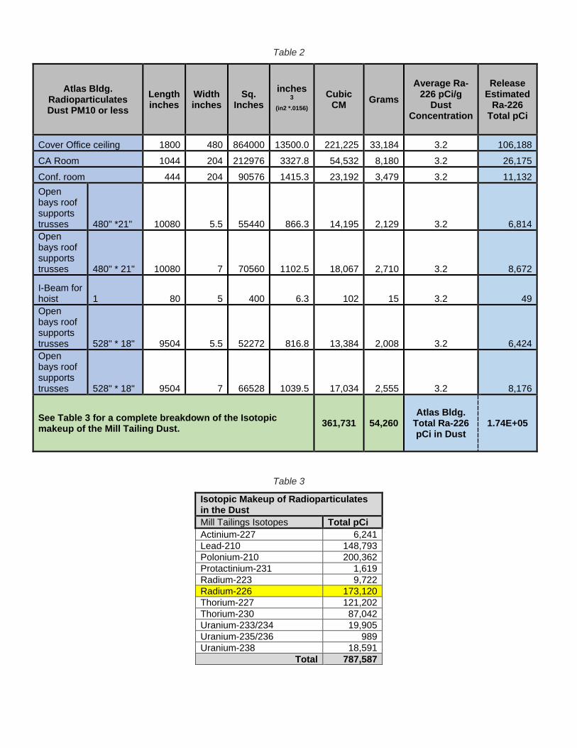
Table 2
Atlas Bldg. Radioparticulates Dust PM10 or less
Length inches
Width inches
Sq. Inches
inches 3
(in2 *.0156)
Cubic CM Grams
Average Ra-226 pCi/g
Dust Concentration
Release Estimated
Ra-226 Total pCi
Cover Office ceiling 1800 480 864000 13500.0 221,225 33,184 3.2 106,188 CA Room 1044 204 212976 3327.8 54,532 8,180 3.2 26,175 Conf. room 444 204 90576 1415.3 23,192 3,479 3.2 11,132 Open bays roof supports trusses 480" *21" 10080 5.5 55440 866.3 14,195 2,129 3.2 6,814 Open bays roof supports trusses 480" * 21" 10080 7 70560 1102.5 18,067 2,710 3.2 8,672
I-Beam for hoist 1 80 5 400 6.3 102 15 3.2 49 Open bays roof supports trusses 528" * 18" 9504 5.5 52272 816.8 13,384 2,008 3.2 6,424 Open bays roof supports trusses 528" * 18" 9504 7 66528 1039.5 17,034 2,555 3.2 8,176
See Table 3 for a complete breakdown of the Isotopic makeup of the Mill Tailing Dust. 361,731 54,260
Atlas Bldg. Total Ra-226 pCi in Dust
1.74E+05
Table 3
Isotopic Makeup of Radioparticulates in the Dust Mill Tailings Isotopes Total pCi Actinium-227 6,241 Lead-210 148,793 Polonium-210 200,362 Protactinium-231 1,619 Radium-223 9,722 Radium-226 173,120 Thorium-227 121,202 Thorium-230 87,042 Uranium-233/234 19,905 Uranium-235/236 989 Uranium-238 18,591
Total 787,587

Calculating Windblown Emissions from the Mill Tailings Pile for a Comparison to a Release from an Atlas Building Fire The fugitive radioactive dust varies significantly from one mill tailings pile to another. Meteorological - conditions (wind, rainfall, and temperatures), exposed surfaces, ore compositions, physical characteristics, particle size distributions, site characteristics, and operational procedures are among the factors that affect the wind dispersion. Calculations: Tailings Pile Emissions from average wind condition The NRC estimated windblown particle emissions, using the method described in MILDOS (NUREG/CR-4088 PNL-5338 RU). In using this approach, the emission factor (Ew) is calculated as follows:
Ew = 3.156 x 10⁷
0.5 x Σs(RsFs)
Where: Ew is the annual dust loss per unit area, g/m2*yr 3.156 x 10⁷ is the number of seconds per year 0.5 is the fraction of the total dust loss constituted by particles < 20 m in diameter RS is the resuspension rate for tailings sands at the average wind speed for wind speed group S, for particles < 20 m in diameter, g/m2*sec. FS is the annual average frequency of occurrence of wind speed group S, obtained from joint relative frequency wind distribution for the site.
The MILDOS-calculated resuspension rates for tailings sands are tabulated in Table 4 for each wind speed group S.
Table 4
Parameters for Calculating Annual Dusting Rate for Exposed Tailings Sands
Wind Speed Group, knots
Average Wind Speed mph
Dusting Rate (Rs) g/m2 *sec
0-3 1.5 0 4-6 5.5 0 7-10 10.0 3.92 x 10⁻⁷ 11-16 15.5 9.68 x 10⁻⁶ 17-21 21.5 5.71 x 10⁻⁵ 21+ 28 2.08 x 10⁻⁴
The source term for each mill tailings pile area is then calculated as:
S = Ew A C fN(1 - R) Where: Ew is the emission factor in g/m2*yr, as calculated above A is the exposed surface area of the mill tailings pile in m2 C is the contaminant concentration in percent or pCi/g of uranium f is the fraction of a particular contaminant present; N is the activity enrichment ratio of concentration in dust/bulk material; R is a control factor depending on the degree of control applied (see NUREG/CR-4088 PNL-5338 RU Appendix C).

To calculate the radium-226 release from the Moab UMTRA tailings pile stabilized with routine water sprayed onto the tailings (R = 0.5, from •NUREG/CR-4088 PNL-5338 RU, Appendix C). The pile area, A, is 130 acres and contains 99.5 percent of the 364 pCi 226 Ra/g originally in the ore. However, out of the130 acres, only 97.5 acres are exposed to the wind effects. The annual average frequency of occurrence of each wind speed group, resuspension factor, and their product are shown in Table 5.
Table 5
Parameters for Calculating Tailings Emission Factor
Wind Speed Group, knots
Resuspension Ratea
(RS), g/m2*s Frequency of Occurrence, b (FS)
Product, RS X FS g/m2*s
0-3 0 0.40 0 4-6 0 0.36 0 7-10 3.92 x 10⁻⁷ 0.14 5.49 x 10⁻⁸ 11-16 9.68 x 10⁻⁶ 0.025 2.42 x 10⁻⁷ 17-21 5.71 x 10⁻⁵ 0.0075 4.28 x 10⁻⁷ 21+ 2.08 x 10⁻⁴ 0.0062 1.29 x 10⁻⁶
∑s=2.01x10⁻⁶
a Dusting rate of a function of wind speed is computed by the MILDOS code (NRC 1981). b Wind speed frequencies obtained from annual data for the Moab UMTRA site.
The calculated emission factor (annual average dust loss rate) is: Ew = 3.156x10⁷ s/yr x 2.01x10⁻⁶g/m2*s / (0.5) = 1.27x10² g/m2/yr
The Moab UMTRA Project tailings pile radium-226 source term is therefore: S = 1.27x10² g/m2*yr x 97.5 acres x 4047 m2/acre x 364 pCi 226Ra/g x 10-12 Ci/pCi x 0.995 x 2.5 x (0.5) = 2.27x10⁻² Ci 226Ra/yr. or 2.27x10¹⁰ pCi 226Ra/yr. which equates to 6.22x10⁷ pCi 226Ra/day.
The Moab UMTRA Project Atlas Building estimated radium-226 source term is therefore: S = 1.27x10² g/m2*yr x 911.5 m2 x 3.2 pCi 226Ra/g x 10-12 Ci/pCi x 0.995 x 2.5 = 9.21x10⁻⁷ Ci 226Ra/yr. or 9.21x10⁵ pCi 226Ra/yr. which equates to 2.52x10³ pCi 226Ra/day.
Estimating Radioparticulates Transport Distance In order to calculate how far the mill tailings dust can travel, the terminal velocity of the particles must be determined. This will allow us to find out how long it will take for the particles to fall from a particular height. Once this period has been determined, the distance which a particle can travel is a function of the wind speed. Calculations for 10 μm Particles: (Respiratory and Allergic Immune Response Impacts of Gravel Pit/ Quarry Operations on Adjacent Land/ Properties). Dust of this size is the median inhalable diameter specified by the EPA. “The EPA describes inhalable dust as that size fraction of dust which enters the body, but is trapped in the nose, throat, and upper respiratory tract.” The terminal velocity of this size of particle is calculated to be 7.53E-03 m/s using Stokes Law for Fluid-Particle Forces, in the conditions specified previously. It will therefore take 664 seconds for these particles to fall from a height of 5 meters.

Wind Speed Travel Distance 5 km/h (3.1 mph) 0.9 km (.55 mile) 10 (6.2 mph) 1.8 (1.1 miles) 20 (12.4 mph) 3.7 (2.3 miles) 40 (24.8 mph) 7.4 (4.6 miles) 60 (37.3 mph) 11.1 (6.9 miles) 80 (49.7 mph) 14.8 (9.2 miles) Calculations for 5 μm Particles: Dust of this size falls within the respirable dust range as specified by the EPA. Respirable dust refers to; “those dust particles that are small enough to enter the nose and upper respiratory system and penetrate deep into the lungs. Particles that penetrate deep into the respiratory system are generally beyond the body's natural clearance mechanisms of cilia and mucous and are more likely to be retained.” The terminal velocity of this size of particle is calculated to be 1.91E-03 m/s using Stokes Law for Fluid-Particle Forces, in the conditions specified previously. It will therefore take 2,612 seconds for these particles to fall from a height of 5 meters. Wind Speed Travel Distance 5 km/h (3.1 mph) 3.6 km (2.2 miles) 10 (6.2 mph) 7.3 (4.5 miles) 20 (12.4 mph) 14.5 (9 miles) 40 (24.8 mph) 29.0 (18 miles) 60 (37.3 mph) 43.5 (27 miles) 80 (49.7 mph) 58.1 (36.1 miles) UNDERSTANDING THE IMPACTS OF A POSSIBLE FIRE INTHE ATLAS BUILDING Radioparticulates Release To better understand the impacts of an Atlas Building fire we have compared the fire to a similar risk profile, the mill tailings pile, which is located near the Atlas Bldg. The pile is exposed to both wind erosion and particulate loss, which follows the same air particulate flow pattern as would airflow from an Atlas building fire. When comparing the estimated daily release of radioparticulates from an Atlas Building fire, to the estimated release of windblown particulates from the pile, the release due to a fire in Atlas building would be less than 0.001% of the daily release from the pile during average wind conditions.

ALARA Precaution and Considerations There are steps that take place when these type of events happen, for example:
• Evacuation of affected areas, this includes the removal of personnel vehicles. • Radiological surveys of vehicles and property. • Additional air monitoring in critical areas.
Note: These ALARA steps accomplish two important factors: 1. Documentation of the event. 2. Maintaining good contamination controls.
Other possible Impacts
Although Arches Nation Park is only a mile away from the site, the impact from a fire in the Atlas building would have very little, to no effects, on the park.
In Summary If the Atlas Building did catch fire there would be little to no impact to the project, surrounding community, or environment. The amount of low-level radioactivity released would be extremely small.
References: • NUREG/CR-4088 PNL-5338 RU, “Methods for Estimating Radioactive and Toxic
Airborne Source Terms for Uranium Milling Operations”
Respiratory and Allergic Immune Response Impacts of Gravel Pit/ Quarry Operations on Adjacent Land/ Properties
6.22x10⁷ 2.25x10³
Comparing 226Ra Release from the Mill Tailings Pile to an Atlas Building Fire
In pCi per day
Mill Tailing Pile Release Release from a fire in the Atlas Bfdg

Attachment 4.
White Paper –Adjusting the Derived Air Concentration Values
at the Mill Tailings Pile based on Isotopic Analysis
December 2018
by Ron Daily, Ken Schafer, Colette Johnston
TABLE OF CONTENTS Section Page 1.0 Background and History of Mill Tailings Pile .....................................................................1 2.0 Decision to Sample the Mill Tailings ..................................................................................2 3.0 Isotopic Composition of the Moab Mill Tailings ................................................................3 4.0 Dose Comparison of HPP vs GEL Laboratories Isotopic Ratios ........................................4 5.0 Evaluation of the Radionuclide in the Mill Tailings ............................................................5 6.0 Modified DAC Equation ......................................................................................................8 7.0 Resuspension Factor ............................................................................................................9 8.0 Particle Size Estimation .......................................................................................................9 9.0 Isotopic Absorption Type ....................................................................................................9 10.0 Evaluations .........................................................................................................................10 11.0 Conclusion .........................................................................................................................11 12.0 References ..........................................................................................................................11
Charts
Chart 1. Isotopic Ratio Comparison ............................................................................................3 Chart 2. IMBA Isotopic Dose Comparison…………………………………………………….4
Figures
Figure 1. Uranium-238 Decay Chain ............................................................................................6 Figure 2. Uranium-235 Decay Chain ............................................................................................7 Figure 3. Thorium-232 Decay Chain ............................................................................................8
Tables
Table 1. Mill Tailing Isotopic Ratios ...........................................................................................3 Table 2. Mill Tailings Radionuclide Absorption Types ............................................................10 Table 3. Activity/U-Nat Ratios ..................................................................................................10
Attachments
Attachment 1 .RRM Collection Documentation

1.0 Background and History of the Mill Tailings Pile The Uranium Reduction Company constructed the mill in 1956 outside Moab, Utah and operated it until 1962 when the assets were sold to Atlas Minerals Corporation (Atlas). Uranium concentrate (called yellowcake), the milling product, was sold to the U.S. Atomic Energy Commission through December 1970 for use in national defense programs. After 1970, production was primarily for commercial sales to nuclear power plants. During its years of operation, the mill processed an average of about 1,400 tons of ore each day. The milling operations created process-related wastes and tailings, a radioactive sand-like material. The tailings were pumped to an unlined impoundment in the western portion of the property, accumulating over time forming a pile more than 80 feet thick. Although more than 90 percent (%) of the uranium was removed during processing, radium and other decay products remained in the tailings, with an average radioactivity of about 660 picocuries per gram (pCi/g) of radium-226 (Ra-226). The tailings, especially in the center of the pile, have a high water content. In the past, excess water in the pile drained through underlying soils, contaminating the groundwater. Atlas operated the site until 1984 under a license and regulatory authority provided by the U.S. Nuclear Regulatory Commission (NRC). Atlas demolished the processing buildings and buried them in the southwestern corner of the tailings pile and placed an interim cover over the pile as part of decommissioning activities conducted between 1988 and 1995. There was an estimated 12 million cubic yards (16 million tons) of mill tailings and other contaminated materials present in the pile. Atlas proposed to stabilize the tailings pile at Moab by permanently capping it in place. However, Atlas declared bankruptcy in 1998 and, in doing so, relinquished its license. Because the NRC could not legally possess a site it regulated, NRC appointed PricewaterhouseCoopers as the trustee of the Moab Mill Reclamation Trust and licensee for the site. The trustee initiated site reclamation, conducted groundwater studies, and performed site maintenance activities. In 2008 and 2009, as a part of the Uranium Mill Tailings Remedial Action (UMTRA) program, the U.S. Department of Energy (DOE) performed extensive infrastructure construction at the Moab tailings pile and at a disposal site in Crescent Junction, Utah in preparation for moving the contents of the tailings pile, known as residual radioactive material (RRM). In April 2009, DOE began relocating the RRM to the disposal cell in Crescent Junction, located 30 miles from the Moab site. RRM is excavated and conditioned in drying beds to reach the optimal moisture content for disposal. The material is then placed in steel containers with locking lids for transport by train to Crescent Junction. A gantry crane is used to transfer containers to and from the train at Moab. To date, the Project has shipped more than 9 million tons of tailings, or 58 percent of the total. 2.0 Decision to Sample the Mill Tailings A requirement of Title 10 Code of Federal Regulations Part 835 (10 CFR 835), “Occupational Radiation Protection,” is that the site contractor have a comprehensive understanding of the source term that their workers are exposed to. To obtain an accurate dose measurement, there must be sufficient technical data of the source term in order to input the data into a biokinetic model. In the startup phases of the project, numerous RRM samples were collected, however,

most of the samples were only analyzed for Ra-226. Therefore, a complete understanding of the isotopic ratios was never determined. The Project used an ultra-conservative assumption when developing the original dose modeling. For example, the Moab UMTRA Health Physics Plan (DOE-EM/GJ3003) stated all isotopes were in secular equilibrium with the parent and that all the prodigy isotopes had the same activity per gram. This was done in an effort to use the most conservative numbers and was incorrect. The isotopic ratios were determined by establishing a conservative list of long-lived alpha emitters found in the three naturally occurring decay chains. The importance of the mill tailing ratios became more evident when the Project determined that there was a technical shortfall in the bioassay program. This shortfall was due to the extreme solubility of the uranium present (U-234, U-235, and U-238), which remains in the body less than 30 days. Due to this shortfall, the Project decided to assign dose by utilizing air monitoring results unless there was a positive bioassay sample. 3.0 Isotopic Composition of the Moab Mill Tailings In calendar year 2007 (CY07), as part of the UMTRA Project startup, a technical basis manual was required to be developed in accordance with 10 CFR 835. As mentioned in section 2.0 the data used for this was not accurate. Table 1 and Chart 1 illustrate a comparison of the HPP (CY07) isotopic data, and the collected and analyzed tailings isotopic data from CY18.
Table 1. Mill Tailing Isotopic Ratios
Mill Tailings Isotopes Health Physics Plan 20071
Mill Tailings Analysis 2018 GEL Labs Data
U-Nat (U234, 235, 238) 2.6% 6.11% Ra-226 31.1% 20.86% Po 210 31.1% 22.00% Ac-227 1.37% 0.89% Th-230 31.1% 12.10% Pa-231 1.37% 0.57% Th-227 1.0% 16.52% Ra-223 0.90% 1.26% Pb-2102 0 19.7%
1 The 2007 Health Physics Plan Isotopic Ratios were a conservative estimate. 2 Pb-210 was not included in the HPP column Table 1 ratios. Pb-210 decay mode has the following Branching percentage; Beta 100% and Alpha 1.9 e-64%, and therefore was not included in the derived air concentration (DAC) calculation nor the IMBA dose model based on its long lived Alpha percentage.

Chart 1. Isotopic Ratio Comparison
2.58%
62.20%
1.37%
31.10%
1.37%1.00% 0.90% 0.00%
6.11%
42.86%
0.89%12.10%
0.57%
16.52%
1.26%
19.70%
0.00%
10.00%
20.00%
30.00%
40.00%
50.00%
60.00%
70.00%
U-Nat (U234,235, 238)
RA-226+Po 210 Ac-227 Th-230 Pa-231 Th-227 Ra-223 Pb-210
Mill Tailings Istopic Ratios
In 2007 HPP In 2018 New Data

4.0 Dose Comparison of HPP vs Soil Sample Isotopic Ratios A bioassay sample result of 0.3microgram per liter (µg/L) U-Nat, using the isotopic chronic dose breakdown of the main long-lived gross alpha decaying nuclides, and based on the ratios defined in the HPP (CY07) would produce the following results for thorium 230 (Th-230), Ra-226, protactinium 231(Pa-231), actinium 227 (Ac-227), U-Nat, and polonium 231 (Po-210). This results in a CED of 141.45 mrem.
• Th-230 24.00 mrem • Ra-226 6.80 mrem • Pa-231 12.70 mrem
• Ac-227 90.80 mrem • U-Nat 0.17 mrem • Po-210 6.98 mrem
Using Integrated Modules for Bioassay Analysis (IMBA) to calculate the dose with the isotopic ratios from the soil samples produces a lower CED assignment of 35.45 mrem, as shown below and in Chart 2.
• Th-230 3.99 mrem • Ra-226 1.95 mrem • Pa-231 2.25 mrem
• Ac-227 25.10 mrem • U-Nat 0.17 mrem • Po-210 1.99 mrem

NOTE: The above data was derived from a chronic dose, calculated using a start date of 02/12/2018 to 05/21/2018 and a measurement error of 0.0405. Also, due to the short half-lives, and low percent of contribution to the actual dose, Th-227 and Ra-223 have been omitted from the IMBA software and the above calculations, but are utilized in the derived air concentration (DAC) calculation.
Chart 2. IMBA Isotopic Dose Comparison
24.00
6.80
12.70
90.80
0.17
6.98
3.99
1.95
2.25
25.10
0.17
1.99
05
101520253035404550556065707580859095
100
Th-230 Ra-226 Pa-231 Ac-227 U-Nat Po-210
mre
m C
ED
IMBA Isotopic Dose Comparison
HPP Conservative Date GEL Analyzied Data
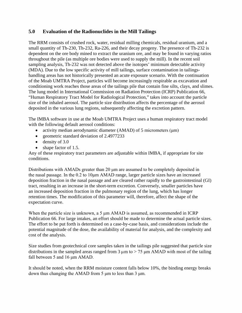
5.0 Evaluation of the Radionuclides in the Mill Tailings The RRM consists of crushed rock, water, residual milling chemicals, residual uranium, and a small quantity of Th-230, Th-232, Ra-226, and their decay progeny. The presence of Th-232 is dependent on the ore body mined to extract the uranium ore, and may be found in varying ratios throughout the pile (as multiple ore bodies were used to supply the mill). In the recent soil sampling analysis, Th-232 was not detected above the isotopes’ minimum detectable activity (MDA). Due to the low specific activity of mill tailings, surface contamination in tailings-handling areas has not historically presented an acute exposure scenario. With the continuation of the Moab UMTRA Project, particles will become increasingly respirable as excavation and conditioning work reaches those areas of the tailings pile that contain fine silts, clays, and slimes. The lung model in International Commission on Radiation Protection (ICRP) Publication 66, “Human Respiratory Tract Model for Radiological Protection,” takes into account the particle size of the inhaled aerosol. The particle size distribution affects the percentage of the aerosol deposited in the various lung regions, subsequently affecting the excretion pattern. The IMBA software in use at the Moab UMTRA Project uses a human respiratory tract model with the following default aerosol conditions:
• activity median aerodynamic diameter (AMAD) of 5 micrometers (μm) • geometric standard deviation of 2.4977233 • density of 3.0 • shape factor of 1.5.
Any of these respiratory tract parameters are adjustable within IMBA, if appropriate for site conditions. Distributions with AMADs greater than 20 μm are assumed to be completely deposited in the nasal passage. In the 0.2 to 10μm AMAD range, larger particle sizes have an increased deposition fraction in the nasal passage and are cleared rather rapidly to the gastrointestinal (GI) tract, resulting in an increase in the short-term excretion. Conversely, smaller particles have an increased deposition fraction in the pulmonary region of the lung, which has longer retention times. The modification of this parameter will, therefore, affect the shape of the expectation curve. When the particle size is unknown, a 5 μm AMAD is assumed, as recommended in ICRP Publication 66. For large intakes, an effort should be made to determine the actual particle sizes. The effort to be put forth is determined on a case-by-case basis, and considerations include the potential magnitude of the dose, the availability of material for analysis, and the complexity and cost of the analysis. Size studies from geotechnical core samples taken in the tailings pile suggested that particle size distributions in the sampled areas ranged from 3 µm to > 75 μm AMAD with most of the tailing fall between 5 and 16 μm AMAD. It should be noted, when the RRM moisture content falls below 10%, the binding energy breaks down thus changing the AMAD from 5 μm to less than 3 μm.

In mill tailings, approximately 90%, or more, of the activity, due to uranium isotopes, has been removed in the milling process. Except for U-235, the actinium decay chain radionuclides are assumed to be in equilibrium with each other and exist at 4.7 percent of the U-238 decay chain activity. Uranium, radium, and thoron (Rn-220) occur in three natural decay series, headed by U-238, Th-232, and U-235, respectively. In nature, the radionuclides in these three series are approximately in a state of secular equilibrium, in which the activities of all radionuclides within each series are nearly equal. The radionuclides of these three decay series are shown in Figures 1, 2, and 3, along with the primary modes of decay for each. In mill tailings, the top of the decay chain has been removed, leaving Th-230, Ra-226, and Ra decay progeny, mainly radon (Rn-222), as the primary radionuclides of concern.
Figure 1. Uranium-238 Decay Chain When looking at Figure 1, it should be noted that most of the uranium has been removed in the milling process (approximately 90 to 93 percent). The two long-lived radionuclides (Th-230 and Ra-226) may not be co-located in equal activity concentrations due to various chemical extraction and sorting processes that have occurred. Lead-210 (Pb-210) should be reasonably close to full equilibrium with Ra-226, however, analysis cannot be validated by the IMBA data. Also, note that a fraction of the Ra-226 progeny is liberated via the airborne release of Rn-222.
Bi = bismuth; MeV = mega electron volt; Pb = lead; Po = polonium Tl = thalium

Figure 2. Uranium-235 Decay Chain
Bi = bismuth; Po = polonium Tl = thalium
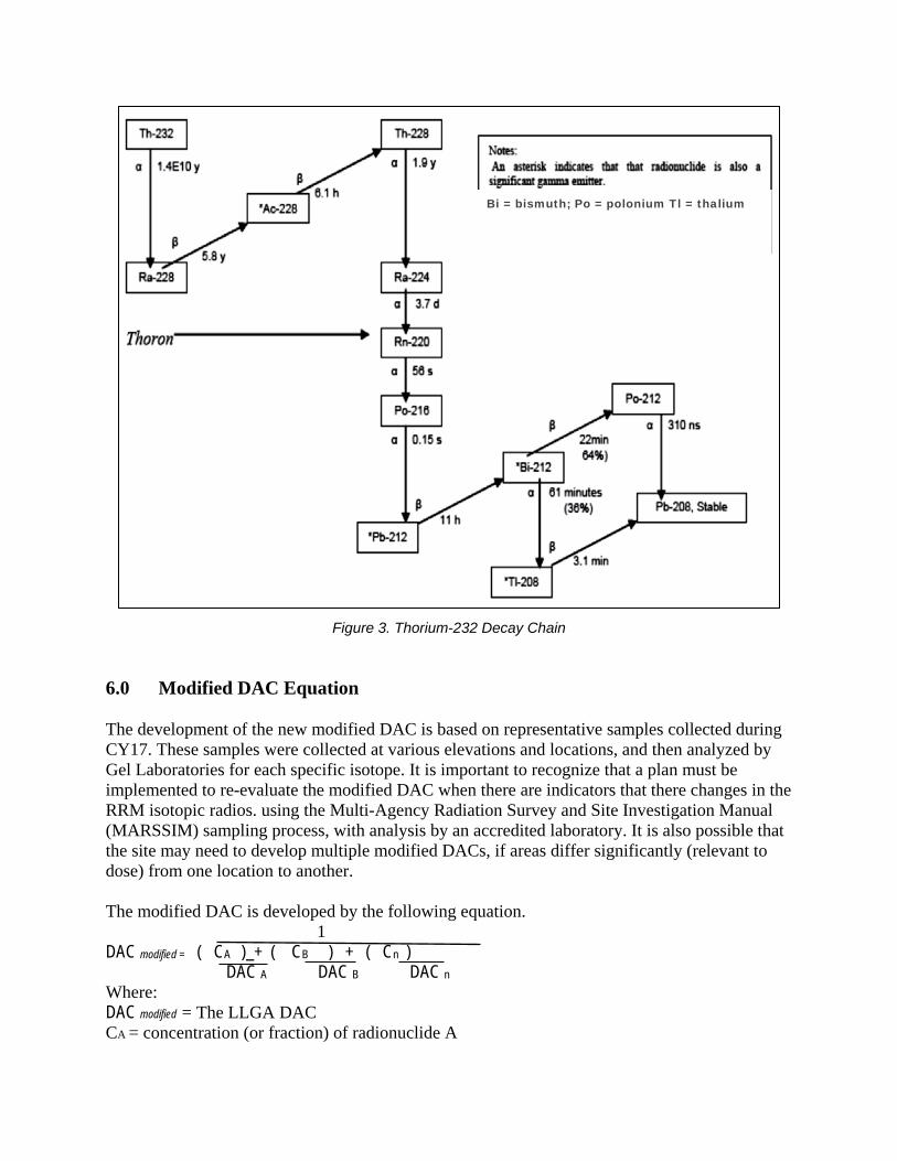
Figure 3. Thorium-232 Decay Chain 6.0 Modified DAC Equation The development of the new modified DAC is based on representative samples collected during CY17. These samples were collected at various elevations and locations, and then analyzed by Gel Laboratories for each specific isotope. It is important to recognize that a plan must be implemented to re-evaluate the modified DAC when there are indicators that there changes in the RRM isotopic radios. using the Multi-Agency Radiation Survey and Site Investigation Manual (MARSSIM) sampling process, with analysis by an accredited laboratory. It is also possible that the site may need to develop multiple modified DACs, if areas differ significantly (relevant to dose) from one location to another. The modified DAC is developed by the following equation. 1 DAC modified = ( CA ) + ( CB ) + ( Cn ) DAC A DAC B DAC n Where: DAC modified = The LLGA DAC CA = concentration (or fraction) of radionuclide A
Bi = bismuth; Po = polonium Tl = thalium

CB = concentration (or fraction) of radionuclide B Cn = concentration (or fraction) of radionuclide N, and so on The original equation for the modified DAC per the Health Physics Plan is shown below. 𝐷𝐷𝐷𝐷𝐷𝐷𝑚𝑚𝑚𝑚𝑚𝑚𝑚𝑚𝑚𝑚𝑚𝑚𝑚𝑚
=1
�0.0258𝑈𝑈𝑈𝑈𝑈𝑈𝑈𝑈5𝑒𝑒−10 � + �0.6220𝑅𝑅𝑈𝑈226+𝑃𝑃𝑚𝑚210
2𝑒𝑒−10 � + �0.0137𝐴𝐴𝐴𝐴2272𝑒𝑒−13 � + �0.311𝑇𝑇ℎ230
4𝑒𝑒−11 � + �0.0137𝑃𝑃𝑈𝑈2311𝑒𝑒−12 � + �0.0100𝑇𝑇ℎ227
7𝑒𝑒−11 � + �0.0090𝑅𝑅𝑈𝑈2239𝑒𝑒−11 �
= 1.0 E-11 µCi/ml The equation for the new modified DAC based on actual CY17 analyzed samples is shown here. 𝐷𝐷𝐷𝐷𝐷𝐷𝑚𝑚𝑚𝑚𝑚𝑚𝑚𝑚𝑚𝑚𝑚𝑚𝑚𝑚
=1
�00.0611𝑈𝑈𝑈𝑈𝑈𝑈𝑈𝑈5𝑒𝑒−10 � + �0.4286𝑅𝑅𝑈𝑈226+𝑃𝑃𝑚𝑚210
2𝑒𝑒−10 � + �0.0089𝐴𝐴𝐴𝐴2272𝑒𝑒−13 � + �0.1210𝑇𝑇ℎ230
4𝑒𝑒−11 � + �0.0057𝑃𝑃𝑈𝑈2311𝑒𝑒−12 � + �0.1652𝑇𝑇ℎ227
7𝑒𝑒−11 � + �0.0126𝑅𝑅𝑈𝑈2239𝑒𝑒−11 �
= 1.70 E-11 µCi/ml 7.0 Resuspension Factor No changes were made that would alter the resuspension factor. For purposes of an air sampling program, surface contamination becomes a concern whenever there is a chance that resuspension of the surface contamination can produce airborne activity levels that should be sampled or monitored. If surface contamination levels become high enough, depending on the type of work taking place in the CA, some of the removable surface contamination may become suspended and create a possible inhalation hazard. 8.0 Particle Size Estimation The Project relies on geotechnical results of an extensive borehole sampling campaign as documented in the Final Remedial Action Plan and Site Design for Stabilization of Moab Title I Uranium Mill Tailings At the Crescent Junction, Utah, Disposal Site (DOE-EM/GJ1547). No changes were required based on particle size. 9.0 Isotopic Absorption Type Absorption type classification is used to describe the overall rate of inhaled radioactive material that is transferred into the bloodstream. ICRP Publications 60, 66, and 68 define three absorption types: fast (F), moderate (M), and slow (S) that correlate to the rate material transfers from the respiratory tract into the blood. An absorption type of F has a half-time of 100% at 10 minutes; type M has a half-time of 10% at 10 minutes and 90% at 140 days; and type S has a half-time of 0.1% at 10 minutes and 99.9% at 7,000 days. ICRP Publications 60, 66, and 68 assign various chemical forms of each listed element to one of these three types. If the chemical form of the intake material is known, the type assigned by ICRP Publications 60, 66, and 68 should be assumed. If there is no basis for

specifying the chemical form, then conservative estimates based on the range of values provided for the element in ICRP Publications 60, 66, and 68 should be used. Currently there is no plan to modify any isotopes absorption type as part of this DAC modification. However, Th-230 has a solubility type classified as slow, and in some cases, this can be incorrect. Th-230 can have a higher solubility type due to the leaching process during the time of uranium separation. It is possible to mix multiple classes (e.g., 50% F and 50% S) for a given intake. In the absence of specific information, the Moab Project Internal Dosimetry Program uses the default values as defined in ICRP Publication 68, with the exception of U-Nat, which was changed based upon the results of the leaching data for absorption types listed in Table 2.
Table 2. Mill Tailings Radionuclide Absorption Types
Radionuclide Absorption Type Ac-227 100% Fast Pa-231 100% Moderate
Ra-226, Ra-228 100% Moderate Th-228, Th-230, Th-232 100% Slow
U-234, U-235, U-238 100% Fast As part of the Air Monitoring Program, personal air samples that are above 15% of DAC will be analyzed using a gamma spectroscopy system. Those air samples that indicate high uranium content can be adjusted to the specific mixture based on the ratios shown in Table 3.
Table 3. Activity/U-Nat Ratios
Isotope Activity U-238 0.0288
U-235/236 0.0018 U-234 0.0305 Th-230 0.1210 Ra-226 0.2086 Po-210 0.2200 Pa-231 0.0057 Ac-227 0.089 Th-227 0.1652 Ra-223 0.0126
10.0 Evaluations Evaluations of a new DAC modification shall be based on a significant change in air, soil, or bioassay data, or a substantial change in the excavation profile.

11.0 Conclusion The decision to adopt the new DAC value at the Moab UMTRA Project is based on analysis provided by an accredited laboratory, using representative samples obtained from the mill tailings excavation site. The data in the HPP overestimates the dose to the radiological workers. Therefore, effective immediately, the Radiological Control Manager will authorize use of the new DAC calculations into the Radiological Employee Dosimetry Database System (REDDS), and will implement the new DAC values in our internal dose assignment program. The overall reduction of dose to radiation workers on the Moab UMTRA Project will be a result of evaluations of each individual air sample along with time spent in the CA. The new DAC values of 1.70 E-11 µCi/ml and will only affect CY18 and beyond. 12.0 References 10 CFR 835 (Code of Federal Regulations) “Occupational Radiation Protection,” April 21, 2009. DOE (U.S. Department of Energy) Guide 441.1-1C, “Radiation Protection Programs Guide for Use with Title 10 Code of Federal Regulations Part 835, Occupational Radiation Protection,” May 19, 2008. DOE (U.S. Department of Energy) “Moab UMTRA Project Health Physics Plan” (DOE-EM/GJ3003) Revision 3, July 2015 DOE (U.S. Department of Energy) “Moab UMTRA Project Internal Dosimetry Technical Basis Manual” (DOE-EM/GJ1913) Revision 3, May 2014. ICRP (International Commission on Radiation Protection) Publication 23, “Report of the Task Group on Reference Man,” 1975. ICRP (International Commission on Radiation Protection) Publication 60, “1990 Recommenda-tions of the International Commission on Radiological Protection,” 1991. ICRP (International Commission on Radiation Protection) Publication 66, “Human Respiratory Tract Model for Radiological Protection,” 1994. ICRP (International Commission on Radiation Protection) Publication 68, “Dose Coefficients for Intakes of Radionuclides by Workers,” 1994.

RRM Collection Documentation
Moab UMTRA project soil analysis for determination of modified DAC value Sample Collection Date: October 19, 2017 Container Tare weight: 160.6 g, Including Tape Sample Collection By: Joey Oliver & Micah Martineau
Container # Container Weight Weight Unit Soil Color Weather Conditions
1 1838.1 Grams Light Red Dry & 78oF 2 1797.1 Grams Light Red Dry & 78oF 3 1751.7 Grams Light Red Dry & 78oF 4 1388.5 Grams Light Red Dry & 78oF 5 1349.9 Grams Mixed Dark and light Red Dry & 78oF 6 1686.4 Grams Light Red Dry & 78oF 7 1378.1 Grams Light Red Dry & 78oF 8 1763.8 Grams Light Red Dry & 78oF 9 1762.4 Grams Mixed Dark and light Red Dry & 78oF 10 1614.6 Grams Mixed Dark and light Red Dry & 78oF 11 1759.2 Grams Mixed Dark and light Red Dry & 78oF 12 1552.9 Grams Mixed Dark and light Red Dry & 78oF 13 1704.2 Grams Dark Red Dry & 78oF 14 1571.9 Grams Mixed Dark and light Red Dry & 78oF 15 1364.8 Grams Mixed Dark and light Red Dry & 78oF 16 1646.0 Grams Dark Red Dry & 78oF 17 1544.7 Grams Dark Red Dry & 78oF 18 1824.7 Grams Dark Red Dry & 78oF

RRM Sampling Collection Locations

Attachment 5.
White Paper - Particle Size and Effects Study
CONTENTS SECTION PAGE 1.ABSTRACT ........................................................................................................................................................ 11 2.BACKGROUND ........................................................................................................................11 3.INVESTIGATION ......................................................................................................................12 4.PARTICLE SIZE EFFECT ON DOSE ......................................................................................15 5.CONCLUSIONS.........................................................................................................................16
Attachment 1 ‒ DustTrakTM Monitor Description and Details Attachment 2 ‒ Sensidyne Cyclone Separator Description and Details Attachment 3 ‒ Environmental Conditions and Operational Activities

1.0 Abstract
Since inception of the Moab Uranium Mill Tailings Remedial Action (UMTRA) project, the 10 CFR 835, “Occupational Radiation Protection,” (Appendix A)-mandated 1-micron (µm) particle size assumption has been used for air samples collected on and around the Moab and Crescent Junction sites, and has been used to calculate and assign dose to individual workers based on inhalation of particles. However, as controls have improved and finer-detailed data collection is possible, NorthWind Portage, Inc. (NWP), the Remedial Action Contractor (RAC) decided to investigate the actual particle size to improve the monitoring program and ensure that accurate doses are calculated and assigned to workers. The results of the investigation are that approximately half (30‒70%) of the airborne particles routinely sampled are non-respirable and should not be used to calculate and assign personnel dose. This investigation suggests using a 0.7 multiplier to create an “effective activity” before calculating airborne derived airborne concentration. This value has a factor of approximately 10% conservatism for dose calculations. 2.0 Background
Unlike many radioactive waste sites, the Moab UMTRA project does not have dirt that is contaminated with radioactive materials. Instead, the material being processed (excavated, containerized, transported, and placed for disposal) is the source material, and it has been relatively well homogenized and reduced to small particle sizes by being processed through the uranium mill that previously existed on the site. While the concentrations of the radionuclides in the material vary due to changing processes in the mill, the particle size is fairly consistently small (micron sized). This fact has an advantage in that instead of needing to consider the activity median aerodynamic diameter (AMAD) using more complicated equipment, the project can consider that the airborne radioactive particles are effectively all source material. As such, instead of using a cascade air sampler to determine AMAD, the project can instead use a much faster laser air particle measurement device, and simple one-stage particle size separators for comparison. However, since there is airborne dust at the location independent of the site operations, the laser particle sizing may under- or over-represent the airborne radioactive particle concentration. With more accurate measurements, the breathing zone and fixed air sampling program can be improved to make the measurements more representative of the risk the workers are exposed to by airborne radioactive material. 3.0 Investigation
This investigation has one principal investigation point and several subsidiary points. The principal investigation point is what portion of the airborne radioactive material is “respirable” considering national consensus standards, and therefore what correction factor is most suitable. The subsidiary investigation points are whether single-stage separation devices can provide the required information on an ongoing basis, and if the laser particle sizing device can compare to the actual airborne radioactivity results. The industrial hygiene (IH) discipline, using the American Conference of Governmental Industrial Hygienists (ACGIH) specifications, uses a respirable particle cut-off value of 7 m, as less than 10% of particles above this size can be inhaled (Figure 1). The ACGIH recommendations are referenced in 10 CFR 851, “Worker Safety and Health Program.”

Figure 1. Respirable particle sizes and single-stage particle sizing device response. A calibrated laser particle sizing device (DustTrak™ DRX Aerosol Monitor 8534, Attachment 1) was rented and operated during November 2020, making 7 measurements. The results are shown in Table 1.
Table 1. DustTrakTM Air monitoring results
The SensidyneTM GK 2.69 Cyclone sampler single-stage particle sizing device (Attachment 2) was purchased and operated on 14 occasions over between May and August of 2020. The results are shown in Table 2.
Sampling Date
Sampling Time (min.)
PM1 mg/m^3
PM2.5 mg/m^3
RESP mg/m^3
PM10 mg/m^3
TOTAL mg/m^3
% above PM-10
Respirable percentage
11/2/2020 163 0.018 0.018 0.019 0.025 0.027 22.2 70.4%11/3/2020 133 0.008 0.009 0.009 0.013 0.013 30.8 69.2%11/4/2020 134 0.018 0.018 0.02 0.028 0.032 25 62.5%11/5/2020 150 0.018 0.018 0.019 0.025 0.028 21.4 67.9%
11/10/2020 375 0.012 0.012 0.013 0.024 0.037 29.7 35.1%11/11/2020 400 0.007 0.007 0.008 0.012 0.014 28.6 57.1%11/12/2020 371 0.006 0.006 0.007 0.011 0.013 30.8 53.8%Average 0.012 0.013 0.014 0.020 0.023 26.9 57.9%
Average of measuements: 59%Standard Deviation of measurements: 12%

Table 2. SensidyneTM Cyclone sampler results
Sampling Dates
Standard Sample Head
GK 269 Sample Head Respirable Percentage
05/20/20 3.13E-13 1.43E-13 45.7% 05/21/20 1.56E-13 6.93E-14 44.4% 06/02/20 3.87E-13 1.87E-13 48.3% 06/04/20 5.96E-14 2.42E-14 40.6% 06/08/20 4.03E-14 2.16E-14 53.6% 06/15/20 9.99E-14 4.03E-14 40.3% 06/22/20 6.93E-14 3.87E-14 55.8% 06/24/20 1.63E-13 8.87E-14 54.4% 07/08/20 2.30E-13 1.15E-13 50.0% 07/09/20 2.05E-13 1.05E-13 51.2% 08/17/20 1.64E-13 1.08E-13 65.9% 08/18/20 6.13E-14 2.26E-14 36.9% 08/19/20 9.51E-14 4.47E-14 47.0% 08/20/20 3.87E-14 2.41E-14 62.3%
AVERAGE 1.49E-13 7.37E-14 49.7% STDEV.S 1.02E-13 5.01E-14 8.25%
Average + 1.96 standard deviations = Measurements: 65.92% Average --1.96 standard deviations = Measurements: 33.58%
Despite using different collection systems, and different data resolutions, the results were comparable, with the laser system having an average of 59% respirable particle size, and the cyclone sampler having an average of 49.7% respirable radioactivity. Note that since the devices are measuring different properties, some variation is expected. As the requirements established in 10 CFR 835, Appendix A, are related to radioactivity, the cyclone sampler measurements are closer to representative, and the laser particle sizing device (which also measures non-radioactive particles) should be considered supporting information. 4.0 Particle Size Effect on Dose
While large particles (>10 m) are not respirable and therefore do not result in measurable dose, particle sizes greater than 1 m but below 10 m have smaller assigned dose, as they (in general) do not penetrate as far into the lung and are easier for the body to remove. The Integrated Modules for Bioassay Analysis (IMBA) software was used to calculate Effective Dose for various particle sizes (See Figure) which clearly demonstrates an inverse relationship between dose and particle size.

Figure 2. Effective Dose for Various Particle Sizes
When reviewing the results of the DustTrakTM (Table 1) while considering the dose effects of particle sizes, it is notable that most of the respirable dust is in the 1 m category. Approximately 91% of the respirable dust is in the 1 m category, with 9% being larger particle sizes. It is a conservative assumption to consider all the activity that is respirable to be 1 m AMAD, because the 9% portion that is greater than 1m has a lesser dose consequence. 5.0 Conclusions
Approximately 65.9% of the particles in routine measurements of airborne radioactivity in the air are respirable, and therefore all of the airborne measurements should be multiplied by 0.659 to calculate an “effective air concentration.” This value is the 95% upper confidence level of the actual measured average respirable fraction of airborne radioactive material of 49% (see Table 2). The value of 65% is conservative, and since the respirable fraction is largely 1 m in aerodynamic diameter, no dose corrections based on particle size are necessary following the activity correction. When this respirable fraction correction is applied to the internal dose calculations at the Moab UMTRA Project, the internal dose consequences will drop by 35.6% (removing non-respirable fraction). NWP recommends that this practice should be implemented to accurately calculate and assign dose from airborne radioactive particles. The following actions must be completed to implement the recommendations in this paper: • Update the Internal Dosimetry Technical Basis Manual, Air Monitoring Technical Basis
Manual, and the Radioparticulate Air Sample Analysis Procedure.
• Modify the Radiological Employees Dosimetry Database System (REDDS). The modification would include a mathematical validation process of all dose calculations within the database.
• Place this white paper into the Health Physics Plan along with other approved project white papers.
• Provide technical briefing to the radiological workers who are required to wear the Personal Air Sampling Pumps.
00.10.20.30.40.50.60.70.80.9
1
0 2 4 6 8 10 12
Rela
tive
dose
to
1 µm
Particle AMAD (µm)
Relative calculated Effective Dose for a given particle sizes, as calculated using IMBA

Attachment 1 DustTrakTM Monitor Description and Details
This handheld DRX Aerosol Monitor is a multi-channel, data-logging, laser photometer for real-time aerosol readings. DRX Aerosol Monitor 8534 can simultaneously measure both mass and size fraction. The DustTrak DRX handheld monitor is a multi-channel, battery-operated, data-logging, light-scattering laser photometer that provides real-time aerosol mass readings. Its portable design allows for measurement of dust, fumes, mists, and smoke and is suitable for engineering control evaluations. The DustTrak™ DRX Aerosol Monitor 8534 can simultaneously measure both mass and size fraction. It uses a sheath air system that isolates the aerosol in the optics chamber to keep the optics clean for improved reliability and low maintenance. The procedure used for these measurements is the Aerosol Monitor, Model 8533/8534/8533ep, Operation and Service Manual P/N 6001898, Revision L, December 2014.

Attachment 2 Sensidyne Cyclone Separator Description and Details
The Sensidyne GK 2.69 Cyclone sampler is used to determine activity base on particle size separation. Field measurements were taken. Field measurements were taken in the Contamination Area/Exclusion Zone (CA/EZ) using the GK 2.69 Cyclone sample). The specific location within the CA was chosen based on daily work activity and the likelihood of intake by the monitored workers.
These particle size measurements were conducted to determine what percentage of the activity was related to the particle size and to determine if there would be a reduction based on the use of the particle cutoff of the cyclone device. This was accomplished by collecting field measurement in the vicinity of the residual radioactive material (RRM) loadout operation in the CA/EZ. Stationary samplers were placed in areas with high dust-generating activities. One of the sample heads was the Sensidyne GK 2.69 Cyclone 37-mm while the other sample head was a standard Sensidyne 37-mm sample head. All samples were set up and airflow calibrations performed prior to placement in the CA/EZ. The samples ran for a minimum of 400 minutes. The data in Table 1 (see main text) are designed to evaluate the percentage of particles that are above the respirable intake cutoff of 4 µm. This based on the Sensidyne GK 2.69 Cyclone 50% cutoff at 4 µm.

Attachment 3 Environmental Conditions and Operational Activities
Environmental Conditions during the Time of Particle Size Measurements
Operational Activities During the Time of Particle Size Measurements From November 2, 2020, through November 12, 2020, the following operational activities occurred: Nov. 02 – 05, 2020 • 598 containers across the CA line • 600 containers transported to Crescent Junction • 1 Rewash
Nov. 09 – 11, 2020 • 588 containers across the CA line • 600 containers transported to Crescent Junction • 8 Rewashes